mikromedia 7 for stm32f7 - digi-key sheets...mikromedia 7 for stm32f7 7 return ext_res_initialized;}...
TRANSCRIPT

Mikromedia 7 for STM32F7 1
Mikromedia 7 for STM32F7
mikromedia 7 for STM32F7
mikromedia 7 for STM32F7
IC/Module STM32F746ZG [1]
Interface 1x 26 pinout on board edges
Power supply 3.3V
Website www.mikroe.com/mikromedia/7/stm32f7/ [2]
Schematic PDF schematic [3]
mikromedia 7 for STM32F7 is a compact development system with lots of on-board peripherals which allowdevelopment of devices with multimedia contents. The central part of the system is a 32-bit ARM® Cortex™-M4STM32F746ZG 144-pin microcontroller.The mikromedia 7 for STM32F7 features integrated modules such as stereo MP3 codec, 7” TFT 800x480 touchscreen display. The increased screen size is ideal for displaying larger amounts of data.The board also contains an accelerometer, microSD card slot, buzzer, IR receiver, RGB LED diode, PIN photodiode,temperature sensor, 2.4GHz RF, WiFi, Ethernet and CAN transceivers, 8 Mbit flash memory, RTC battery,Li-Polimer battery charger, etc.Additional components include MINI-B USB connector, power screw terminals, 2x5 JTAG connector, two 1x26connection pads, ON/OFF switch and other. It comes with an onboard mikroProg™ for STM32 programmer anddebugger, but can also be programmed with external programmers, such as ST-LINK programmer.

Mikromedia 7 for STM32F7 2
Power Supply
The mikromedia 7 for STM32F7 board can be powered in four different ways: via two USB connectors usingMINI-B USB cable provided with the board (CN4 or CN11), via battery connector using Li-Polymer battery (CN5)or via adapter connector using adapter power supply (CN3). After you plug in the appropriate power supply turn thepower switch ON (SW1). The USB connection can provide up to 500mA of current which is more than enough forthe operation of all on-board modules and the microcontroller as well. If you decide to use external power supply viascrew terminals, voltage values must be within 5-12V DC range. Power LED ON (GREEN) indicates the presence ofpower supply. On-board battery charger circuit MCP73832 enables you to charge the battery over USB connectionor via screw terminals. LED diode (RED) indicates when battery is charging. Charging current is ~250mA andcharging voltage is 4.2V DC.
STM32F746ZG microcontroller
The mikromedia 7 for STM32F7 development board comes with the 144-pin ARM® Cortex™-M7 STM32F746ZGmicrocontroller. This high-performance 32-bit microcontroller with its integrated modules and in combination withother onboard modules is ideal for multimedia applications

Mikromedia 7 for STM32F7 3
Key microcontroller features•• Up to 462 DMIPS Operation (216 MHz);•• 1 MB of Flash memory;•• 320 + 64 KB of SRAM memory;•• up to 140 I/O pins;•• 16/32-bit timers•• 16MHz internal oscillator, 32kHz RTCC, PLL;•• 4xUART, 3xSPI, 3xI2C, 2xCAN, 3xADC, 3XADC etc.•• Ethernet, USB etc.
Programming the microcontroller
The microcontroller can be programmed in two ways:1. Using onboard mikroProg™ for STM32 programmer2.2. Using external programmers for STM32 (like ST-LINK)
Using mikroProg™ programmerThe microcontroller can be programmed with onboard mikroProg™ for STM programmer and mikroProg Suite™for ARM® software. Connection with PC is established over an PROG USB connector. For proper insertion of theMINI-B USB cable. Signalization LED (LINK) is also provided on the opposite side of the PROG USB connector. Itis also possible to program the microcontroler with external porogrammers, via 2x5 JTAG connector (CN1) with anappropriate adapter.

Mikromedia 7 for STM32F7 4
mikroProg Suite™ for ARM® software
mikroProg™ for STM32 programmer requires special programming software called mikroProg Suite™ for ARM®.This software is used for programming ALL of STM32 ARM® Cortex-M3™ and Cortex-M7™ microcontrollerfamilies. It features intuitive interface and SingleClick™ programming technology. Software installation is availableon following link:www.mikroe.com/downloads/get/1809/mikroprog_suite_for_arm.zip [4]
After downloading, extract the package and double click the executable setup file to start installation.
Software Installation wizard
The board is equipped with reset button, which is located on the front side of the board. If you want to reset thecircuit, press the reset button. It will generate low voltage level on the microcontroller reset pin (input). A reset canalso be externally provided through the pin 26 on the side headers.

Mikromedia 7 for STM32F7 5
RTC Battery and Rest Button
Reset ButtonThe board is equipped with reset button, which is located on the front side of the board. If you want to reset thecircuit, press the reset button. It will generate low voltage level on the microcontroller reset pin (input). A reset canalso be externally provided through the pin 26 on the side headers.
RTC Batterymikromedia 7 for STM32F7 features an RTC battery holder for microcontroller RTC module. Battery is used asalternate source of power, so the RTC module can continue to keep time while the primacy source of power is off orcurrently unavailable. Three types of coin battery are supported: CR1216, CR1220 and CR1225.
Crystal oscillators and 2.048V reference
The board is equipped with 1 25MHz crystal oscillator (X5) circuit that provides external clock waveform to themicrocontroller OSCO and OSCI pins. This base frequency is suitable for further clock multipliers and ideal forgeneration of necessary USB clock, which ensures proper operation of bootloader and your custom USB-basedapplications. The board also contains 2 32.768 kHz crystal oscillator (X4) which provides external clock for internalRTCC module. Microcontroller ADC requires an accurate source of reference voltage signal. That is why weprovide the external 3 voltage reference to the microcontroller VREF pin which is 2.048V.

Mikromedia 7 for STM32F7 6
microSD Card Slot
Board contains 1 microSD card slot for using 2 microSD cards in your projects. It enables you to store large amountsof data externally, thus saving microcontroller memory. microSD cards use Serial Peripheral Interface (SPI) forcommunication with the microcontroller. Ferrite and capcitor are provided to compensate the voltage and currentglitch that can occur when pushing-in and pushing-out microSD card into the socket. Proper insertion of themicroSD card is shown in the image above.This code snippet initializes the FAT32 library for usage with SD card:
void char Init_FAT(){
char FAT_cnt = 0;
if (MMC_Card_Detect == 0){
if (Fat_Initialized_Flag == 0){
while ((Fat32_Init() != 0) && (FAT_cnt < 5))
Fat_cnt ++;
if (FAT_cnt < 5){
SDIO_Init(_SDIO_CFG_POWER_SAVE_DISABLE |
_SDIO_CFG_4_WIDE_BUS_MODE | _SDIO_CFG_CLOCK_BYPASS_DISABLE
| _SDIO_CFG_CLOCK_RISING_EDGE |
_SDIO_CFG_HW_FLOW_DISABLE, 1, &_GPIO_MODULE_SDIO_D0_D3);
Fat_Initialized_Flag = 1;
}
}
if (Ext_res_initialized == 0){
TFT_Set_Ext_Buffer(MyTFT_Get_Data);
Ext_fhandle = FAT32_Open("Ext_reso.RES", 1);
if (Ext_fhandle != 0xFF)
Ext_res_initialized = 1;
}
}

Mikromedia 7 for STM32F7 7
return Ext_res_initialized;
}
Touch Screen
The development system features a 7‘‘ TFT 800x480 display covered with a resistive touch panel. Together theyform a functional unit called a touch screen. It enables data to be entered and displayed at the same time. The TFTdisplay is capable of showing graphics in 262K different colors.For example here is how to programm the SSD1963 display driver to trigger the Fade-in effect on the display:
void BLED_Fade_In(){
int i;
for (i = 1; i < 255; i++){
TFT_Set_DBC_SSD1963(i);
Delay_ms(1);
}
TFT_Set_DBC_SSD1963(255);
}
This is the callibration routine for the touchscreen controller:
void Calibrate() {
TFT_Fill_Screen(CL_BLACK);
TFT_Set_Font(TFT_defaultFont, CL_WHITE, FO_HORIZONTAL);
STMPE610_ClearInterruptFlagsAndFIFO();
TFT_Set_Brush(1, CL_WHITE, 0, 0, 0, 0);
TFT_Circle(0, 0, 3);
STMPE610_CalibratePoint(STMPE610_FIRST_CORNER);

Mikromedia 7 for STM32F7 8
Delay_ms(500);
TFT_Set_Brush(1, CL_BLACK, 0, 0, 0, 0);
TFT_Circle(0, 0, 3);
STMPE610_ClearInterruptFlagsAndFIFO();
TFT_Set_Brush(1, CL_WHITE, 0, 0, 0, 0);
TFT_Circle(0, TFT_DISP_HEIGHT-1, 3);
STMPE610_CalibratePoint(STMPE610_SECOND_CORNER);
Delay_ms(500);
TFT_Set_Brush(1, CL_BLACK, 0, 0, 0, 0);
TFT_Circle(0, TFT_DISP_HEIGHT-1, 3);
STMPE610_ClearInterruptFlagsAndFIFO();
TFT_Set_Brush(1, CL_WHITE, 0, 0, 0, 0);
TFT_Circle(TFT_DISP_WIDTH-1, TFT_DISP_HEIGHT-1, 3);
STMPE610_CalibratePoint(STMPE610_THIRD_CORNER);
Delay_ms(500);
TFT_Set_Brush(1, CL_BLACK, 0, 0, 0, 0);
TFT_Circle(TFT_DISP_WIDTH-1, TFT_DISP_HEIGHT-1, 3);
STMPE610_ClearInterruptFlagsAndFIFO();
TFT_Set_Brush(1, CL_WHITE, 0, 0, 0, 0);
TFT_Circle(TFT_DISP_WIDTH-1, 0, 3);
STMPE610_CalibratePoint(STMPE610_FOURTH_CORNER);
TFT_Set_Brush(1, CL_BLACK, 0, 0, 0, 0);
TFT_Circle(TFT_DISP_WIDTH-1, 0, 3);
Delay_ms(500);
}
Audio Module

Mikromedia 7 for STM32F7 9
mikromedia 7 for STM32F7 features stereo audio codec 1 VS1053. This module enables audio reproduction andsound recording by using 2 stereo headphones with microphone connected to the system via a 3 3.5mm connector(CN2). All functions of this module are controlled by the microcontroller over Serial Peripheral Interface (SPI). INand OUT channels are also provided on side headers (HDR2).This is the function to start playing a chosen MP3 file from the SD card:
void MP3_play(char *Song_Name, char File_No){
current_file = File_No;
Buffer_count = 0;
current_fhandle = FAT32_Open(Song_Name, FILE_READ);
FAT32_Size(Song_Name, &file_size);
Buffer_count = 0;
Total_Buffers = File_size / BUFFER_SIZE;
MP3_Reset_Time();
MP3_Check_Time();
MP3_Set_Volume(100 - level, 100 - level);
UpdateVolumeBar( level, 0);
MP3_Example_State = 2;
}
USB DEVICE connection
ARM® Cortex™-M7 STM32F746ZG microcontroller has integrated USB module, which enables you to implementUSB communication functionality to your mikromedia board. Connection with target USB host is establish over 1MINI-B USB connector. For proper insertion of the 2 MINI-B USB see image above.

Mikromedia 7 for STM32F7 10
USB HOST connectionmikromedia 7 for STM32F7 can also be used as USB HOST which enables microcontroller to establish a connectionwith the target device (eg. USB keyboard, USB mouse, etc). The board provides necessary power supply to thetarget via TPS2041B IC. In order to enable the 1 USB HOST cable to be connected to the board, it is necessary touse the appropriate 2 MINI-B USB to USB type A adapter.
Accelerometer
Onboard ADXL345 accelerometer is used to measure acceleration in three axis: x, y and z. The accelerometerfunction is defined by the user in the program loaded into the microcontroller. Communication between theaccelerometer and the microcontroller is performed via the I 2 C interface. There is an option to select the alternateaccel address with jumper J3.The following function reads 16 measurement samples from the accelerometer and returns the average value:
static void Accel_Average() {
int i, sx, sy, sz, xx, yy, zz;
// sum
sx = sy = sz = 0;
// average accelerometer reading over last 16 samples
for (i=0; i<16; i++) {
ADXL345_Read(&xx, &yy, &zz);
sx += xx;
sy += yy;
sz += zz;
}
// average
readings[0] = sx / 16;

Mikromedia 7 for STM32F7 11
readings[1] = sy / 16;
readings[2] = sz / 16;
}
Flash Memory
Since multimedia applications are getting increasingly demanding, it is necessary to provide additional memoryspace to be used for storing more data. The flash memory module enables the microcontroller to use additional8Mbit flash memory. It is connected to the microcontroller via the Serial Peripheral Interface (SPI).
RF Transceiver

Mikromedia 7 for STM32F7 12
mikromedia 7 for STM32F7 board features RF transceiver chip with 2.4GHz chip antenna. It is suitable for wirelessoperation in the world wide ISM frequency band at 2.400 - 2.4835 GHz with air data rate up to 2Mbps. RFtransceiver module is connected to the microcontroller via the Serial Peripheral Interface (SPI). This RF transceivermodule is widely used for wireless PC peripherals, remote controllers, VoIP headsets, game controllers, sensors,home and commercial automation, active RFID, toys and many more.This function sends a data packet using nRF24L01:
unsigned char nRF_Send_Packet()
{
if ((ucCom_Mode == nRF_RX_MODE) || (ucIRQ_Source != nRF_IDLE))
return 0;
nRF_Write_TX_Pload(&TX_pload, nRF_TX_PLOAD_WIDTH);
nRF_CE_Pin(nRF_CE_PULSE);
ucTry_Ctr = 0;
return 1;
}
Wi-Fi
mikromedia 7 for STM32F7 is equipped with SPWF01SA, a WiFi module with an integrated antenna fromSTMicroelectronics. The module packs a 2.4 GHz IEEE 802.11 b/g/n transceiver and its own STM32 ARMCortex-M3 MCU that offloads the workload from the main microcontroller on the mikromedia. Full featured TCP/IP protocol stacks are also integrated. A BOOT jumper (zero ohm resistor) for updating the firmware on the WiFimodule is located nearby, between the module itself and the WiFi silkscreen markings.This function is used to connect to the WiFi access point and start the web server:
void startServer()
{
Net_Wireless_SPWF01S_SetConfig(_NET_WIRELESS_SPWF01S_CFG_WAIT_TIME,
socketWaitTime);
scanForSSID(mySSID, scanBuf, BUFSIZE, &netType, &chNum, &sigStr,
&capab, macAddr, &wpa, &wpa2, &wps, 10);
netReady = 0;
UpdateDescription("Connecting...");
if ( ( wifiTest = Net_Wireless_SPWF01S_ConnectToAP(mySSID, myPass) )
== _NET_WIRELESS_SPWF01S_OK )

Mikromedia 7 for STM32F7 13
{
while (netReady == 0) {}
UpdateDescription("Connected!");
Net_Wireless_SPWF01S_MakeFile("index.html", html);
Net_Wireless_SPWF01S_MakeFile("led_and_keyb.js", js);
DrawScreen(&Screen1);
TFT_Set_Font (ipLabel.FontName, 0x4229, FO_HORIZONTAL);
TFT_Write_Text(ipLabel.Caption, ipLabel.Left, ipLabel.Top);
Net_Wireless_SPWF01S_GetCurrentIP(ipAddr);
strcat( strcpy(ipLabel.Caption, "Type in your browser: "),
ip2Str(ipAddr, ipStr) );
TFT_Set_Font (ipLabel.FontName, ipLabel.Font_Color,
FO_HORIZONTAL);
TFT_Write_Text(ipLabel.Caption, ipLabel.Left, ipLabel.Top);
}
}
Ethernet transceiver
The development board features an Ethernet transceiver module LAN8720A. It is ideal for local area networking(LAN). If you want to establish connection with a computer, router or other devices, the development board alsocontains a standard RJ-45 connector. Communication over Ethernet is based on data packets called frames. Eachframe contains source and destination addresses and error-checking data so that damaged data can be detected andretransmitted. Signalization LEDs (green and yellow) are on the opposite side of the board.This function queries the DHCP server for an IP address:
static char Ethernet_DHCP() {
char text[20], temp_text[7], i, result = SUCCESS;
unsigned long timeout;
if (ethDhcp_mark == NOT_SUCCESS) {
Ethernet_Message("Obtaining IP ...");

Mikromedia 7 for STM32F7 14
timeout = 0;
while((ethDhcp_mark == NOT_SUCCESS) && (timeout < 3)) {
// init DHCP
ethDhcp_mark = Net_Ethernet_Intern_initDHCP(5) ? SUCCESS :
NOT_SUCCESS;
timeout++;
}
if (ethDhcp_mark == SUCCESS){
// Get obtained IP
memcpy(myIpAddr, Net_Ethernet_Intern_getIpAddress(), 4);
text[0] = 0;
for (i = 0; i < 4; i ++){
ByteToStr(myIpAddr[i], temp_text);
strcat(text, temp_text);
if(i != 3)
strcat(text, ".");
}
// Display it on TFT
Ethernet_Message(text);
}
else {
Ethernet_Message("DHCP not respond");
result = NOT_SUCCESS;
}
Delay_ms(2000);
}
Ethernet_Message("");
return result;
}
CAN communication

Mikromedia 7 for STM32F7 15
Controller Area Network (CAN or CAN bus) is a vehicle bus standard designed to allow microcontrollers anddevices to communicate with each other within a vehicle without a host computer. CAN is a message-based protocol,designed specifically for automotive applications but now also used in other areas such as industrial automation andmedical equipment. mikromedia 7 for STM32F7 is equipped with SN65HVD230 – a 3.3V CAN transceiver and apair of screw terminals which provide microcontrollers with integrated CAN controller with the necessary physicalinterface for CAN communication. Make sure to correctly connect negative and positive differential communicationlines before using this module.
Node termination jumperIf the board is the first and the last node of the CAN network, then TERMINATION jumper should be placed. If theboard is a node in the middle, the jumper should be removed.This short shippet shows the default initialization routine for the CAN module:
CAN_init() {
CAN1InitializeAdvanced(1,5,4,4,1,Can_Init_Flags,
&_GPIO_MODULE_CAN1_PD01);
CAN1SetOperationMode(_CAN_OperatingMode_Initialization);
}
Buzzer
The board is also equipped with a piezo buzzer. It is an electric component which can be used to create sound waveswhen provided with electrical signal. Microcontroller can create sound by generating a PWM signal. Frequency ofthe signal determines the pitch of the sound and duty cycle of the signal can be used to increase or decrease thevolume.This function plays a warning sound on the buzzer (three beeps of 100ms duration each, alternated with a 200msdelay):
void buzzer_warning( void ) {
Sound_Play( 1000, 100 );
Delay_ms( 200 );
Sound_Play( 1000, 100 );
Delay_ms( 200 );
Sound_Play( 1000, 100 );

Mikromedia 7 for STM32F7 16
}
Other modules
The board also contains additional peripherals that can be very useful, such as 1 PIN photodiode, 2 IR receiver, 3RGB led diode and 4 analog temperature sensor. PIN photodiode is a type of photo detector capable of convertinglight into the voltage with high sensitivity and speed of response. It is connected to the microcontroller analog pin.IR receiver is used for infrared remote control systems. The demodulated output signal obtained from IR module canbe directly decoded by a microcontroller. Many of existing standard data formats are supported. RGB (Red, Green ,Blue) diode is suitable for light indication in your design. Each of colour is driven separately by transistor. Theanalog temperature sensor converts temperature to analog voltage and it is directly connected to the microcontrolleranalog pin. Temperature measurement range of mikromedia 7 for STM32F7 board is from -20°C to 70°C.This function reads the current temperature using MCU's 12 bit ADC module:
static void Get_Temperature(){
unsigned long temp;
float temp2;
temp = ADC3_Get_Sample(6);
temp = (unsigned long)(VREF * temp) / 4096;
temp = temp - 500;
Display_Temp(temp, 0);
temp2 = (float)(temp) / 10 * 1.8 + 32;
temp2 = temp2 * 10;
Display_Temp((unsigned long)temp2, 1);
}
This function measures intensity of light using the MCU's 12 bit ADC module:
static unsigned int Get_Light_Intensity(){
unsigned int Light_Intensity;
char *ptr1, *ptr2;
char text[7], temp;
Light_Intensity = ADC3_Get_Sample(7);

Mikromedia 7 for STM32F7 17
Light_Intensity = Light_Intensity / 4;
if (Light_Intensity >= 1000)
Light_Intensity = 1000;
WordToStr(Light_Intensity, text);
ptr1 = text;
ptr2 = Diagram5_Label4_Caption;
while (*ptr1){
if (*ptr1 != ' ')
*ptr2++ = *ptr1;
ptr1++;
}
ptr2--;
temp = *ptr2;
*ptr2++ = '.';
*ptr2++ = temp;
*ptr2++ = ' ';
*ptr2++ = '%';
*ptr2 = 0;
RedrawLabel(Diagram5_Box1.Color, &Diagram5_Label4, 240, 90);
return Light_Intensity;
}
This function displays color provided as an argument on RGB led:
static void Drive_RGB_Diode(TColors *colors){
PWM_TIM2_Set_Duty((int)pwm_period2 / 64 * colors->Green,
_PWM_NON_INVERTED, _PWM_CHANNEL2);
PWM_TIM3_Set_Duty((int)pwm_period1 / 32 * colors->Blue,
_PWM_NON_INVERTED, _PWM_CHANNEL1);
SoftPWM_duty = colors->Red;
}
Mikromedia 7 for STM32F7 18
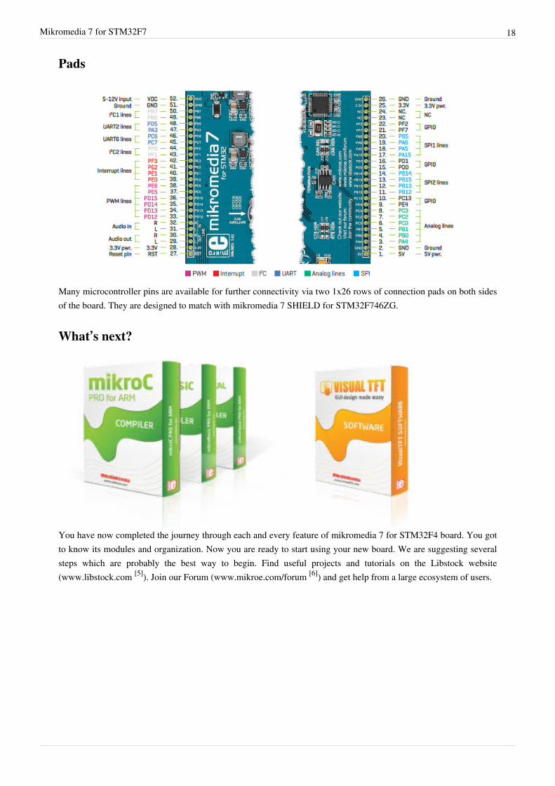
Pads
Many microcontroller pins are available for further connectivity via two 1x26 rows of connection pads on both sidesof the board. They are designed to match with mikromedia 7 SHIELD for STM32F746ZG.
What’s next?
You have now completed the journey through each and every feature of mikromedia 7 for STM32F4 board. You gotto know its modules and organization. Now you are ready to start using your new board. We are suggesting severalsteps which are probably the best way to begin. Find useful projects and tutorials on the Libstock website(www.libstock.com [5]). Join our Forum (www.mikroe.com/forum [6]) and get help from a large ecosystem of users.

Mikromedia 7 for STM32F7 19
CompilerYou still don’t have an appropriate compiler? Locate ARM® compiler that suits you best on our website:www.mikroe.com/arm/compilers [7] Choose between mikroC™, mikroBasic™ and mikroPascal™ and download afully functional demo version, so you can start building your first applications.
Visual TFTOnce you have chosen your compiler, and since you already got the board, you are ready to start writing your firstprojects. Visual TFT software enables you to quickly create your GUI. It will automatically generate codecompatible with MikroElektronika compilers. Visual TFT is rich with examples, which are an excellent startingpoint for your future projects. Download it from www.mikroe.com/visualtft [8]
Resources• mikromedia 7 for STM32F7 landing page [9]
• mikroProg for STM32 drivers download [10]
• mikromedia for STM32F7 Libstock example [11]
References[1] http:/ / www. st. com/ content/ ccc/ resource/ technical/ document/ datasheet/ 96/ ed/ 61/ 9b/ e0/ 6c/ 45/ 0b/ DM00166116. pdf/ files/
DM00166116. pdf/ jcr:content/ translations/ en. DM00166116. pdf[2] http:/ / www. mikroe. com/ mikromedia/ 7/ stm32f7[3] http:/ / cdn-docs. mikroe. com/ images/ a/ a9/ Mikromedia_7_stm32_schematic. pdf[4] http:/ / www. mikroe. com/ downloads/ get/ 1809/ mikroprog_suite_for_arm. zip[5] http:/ / www. libstock. com[6] http:/ / www. mikroe. com/ forum[7] http:/ / www. mikroe. com/ arm/ compilers[8] http:/ / www. mikroe. com/ visualtft[9] http:/ / www. mikroe. com/ mikromedia/ 7/ stm32f7/[10] http:/ / www. mikroe. com/ downloads/ get/ 2444/ st_link_v2_usb_driver. zip[11] http:/ / libstock. mikroe. com/ projects/ view/ 1926/ mikromedia-7-for-stm32f7

Article Sources and Contributors 20
Article Sources and ContributorsMikromedia 7 for STM32F7 Source: http://docs.mikroe.com/index.php?oldid=1676 Contributors: Andrea.galizia, Srdjan.misic
Image Sources, Licenses and ContributorsFile:Mikromedia-7-stm32f7.jpg Source: http://docs.mikroe.com/index.php?title=File:Mikromedia-7-stm32f7.jpg License: unknown Contributors: Srdjan.misicfile:M7-2.jpg Source: http://docs.mikroe.com/index.php?title=File:M7-2.jpg License: unknown Contributors: Srdjan.misicfile:M7-4.jpg Source: http://docs.mikroe.com/index.php?title=File:M7-4.jpg License: unknown Contributors: Srdjan.misicfile:M7-5.jpg Source: http://docs.mikroe.com/index.php?title=File:M7-5.jpg License: unknown Contributors: Srdjan.misicfile:M7-8.jpg Source: http://docs.mikroe.com/index.php?title=File:M7-8.jpg License: unknown Contributors: Srdjan.misicfile:M77-9.jpg Source: http://docs.mikroe.com/index.php?title=File:M77-9.jpg License: unknown Contributors: Srdjan.misicfile:M7-12.jpg Source: http://docs.mikroe.com/index.php?title=File:M7-12.jpg License: unknown Contributors: Srdjan.misicfile:M7-14.jpg Source: http://docs.mikroe.com/index.php?title=File:M7-14.jpg License: unknown Contributors: Srdjan.misicfile:M7-16.jpg Source: http://docs.mikroe.com/index.php?title=File:M7-16.jpg License: unknown Contributors: Srdjan.misicfile:M7-18.jpg Source: http://docs.mikroe.com/index.php?title=File:M7-18.jpg License: unknown Contributors: Srdjan.misicfile:M7-20-1.jpg Source: http://docs.mikroe.com/index.php?title=File:M7-20-1.jpg License: unknown Contributors: Srdjan.misicfile:M7-24.jpg Source: http://docs.mikroe.com/index.php?title=File:M7-24.jpg License: unknown Contributors: Srdjan.misicfile:M7-26.jpg Source: http://docs.mikroe.com/index.php?title=File:M7-26.jpg License: unknown Contributors: Srdjan.misicfile:M7-28.jpg Source: http://docs.mikroe.com/index.php?title=File:M7-28.jpg License: unknown Contributors: Srdjan.misicfile:M77-30.jpg Source: http://docs.mikroe.com/index.php?title=File:M77-30.jpg License: unknown Contributors: Srdjan.misicFile:M7-32.jpg Source: http://docs.mikroe.com/index.php?title=File:M7-32.jpg License: unknown Contributors: Srdjan.misicfile:M77-34.jpg Source: http://docs.mikroe.com/index.php?title=File:M77-34.jpg License: unknown Contributors: Srdjan.misicfile:M77-36.jpg Source: http://docs.mikroe.com/index.php?title=File:M77-36.jpg License: unknown Contributors: Srdjan.misicfile:M77-38.jpg Source: http://docs.mikroe.com/index.php?title=File:M77-38.jpg License: unknown Contributors: Srdjan.misicFile:Mikromedia-7-stm32f7-pinout.jpg Source: http://docs.mikroe.com/index.php?title=File:Mikromedia-7-stm32f7-pinout.jpg License: unknown Contributors: Srdjan.misicfile:M77-42.jpg Source: http://docs.mikroe.com/index.php?title=File:M77-42.jpg License: unknown Contributors: Srdjan.misic
LicenseCreative Commons Attributionhttps:/ / creativecommons. org/ licenses/ by/ 4. 0/