mike bassingthwaite - dot.nd.govjob 10\addendum 1...mb:mb enclosure mike bassingthwaite. spec no....
TRANSCRIPT
Professionals you need, people you trust
P.O. Box 667• 1999 4th Street N. Suite A • Wahpeton, ND 58074-0667 • P: 701-642-5521 • F: 701-642-5215 • www.interstateeng.com
Offices in: North Dakota • Montana • Minnesota • South Dakota
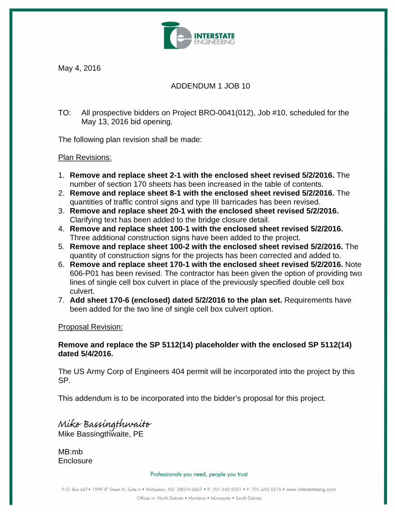
May 4, 2016
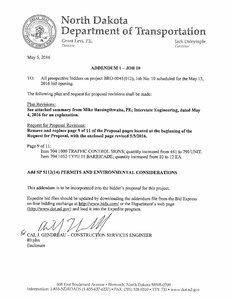
ADDENDUM 1 JOB 10 TO: All prospective bidders on Project BRO-0041(012), Job #10, scheduled for the
May 13, 2016 bid opening. The following plan revision shall be made: Plan Revisions: 1. Remove and replace sheet 2-1 with the enclosed sheet revised 5/2/2016. The
number of section 170 sheets has been increased in the table of contents. 2. Remove and replace sheet 8-1 with the enclosed sheet revised 5/2/2016. The
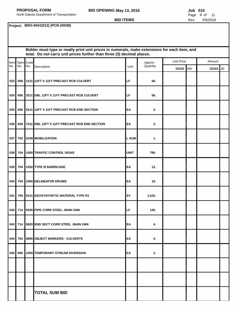
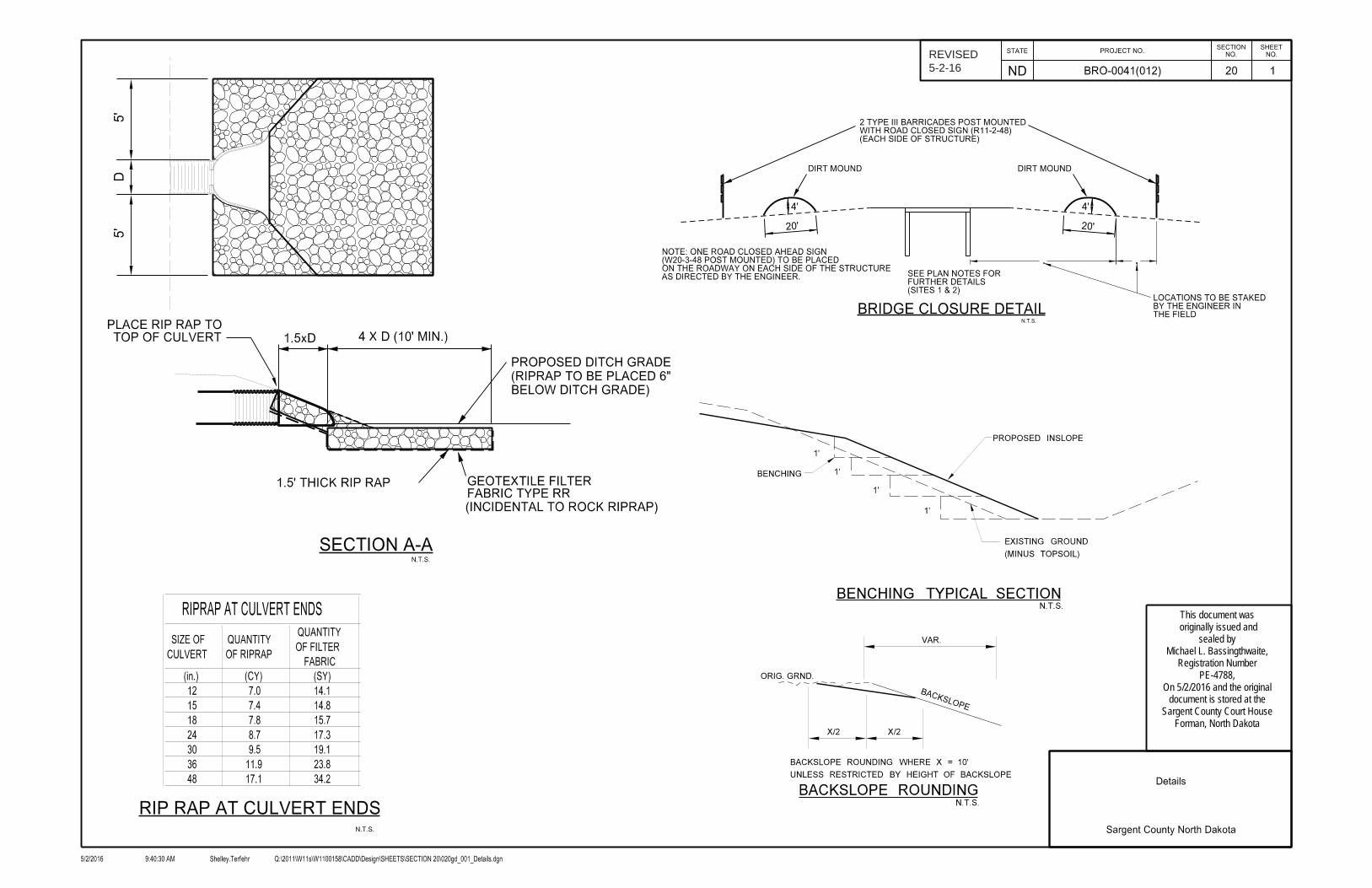
quantities of traffic control signs and type III barricades has been revised. 3. Remove and replace sheet 20-1 with the enclosed sheet revised 5/2/2016.
Clarifying text has been added to the bridge closure detail. 4. Remove and replace sheet 100-1 with the enclosed sheet revised 5/2/2016.
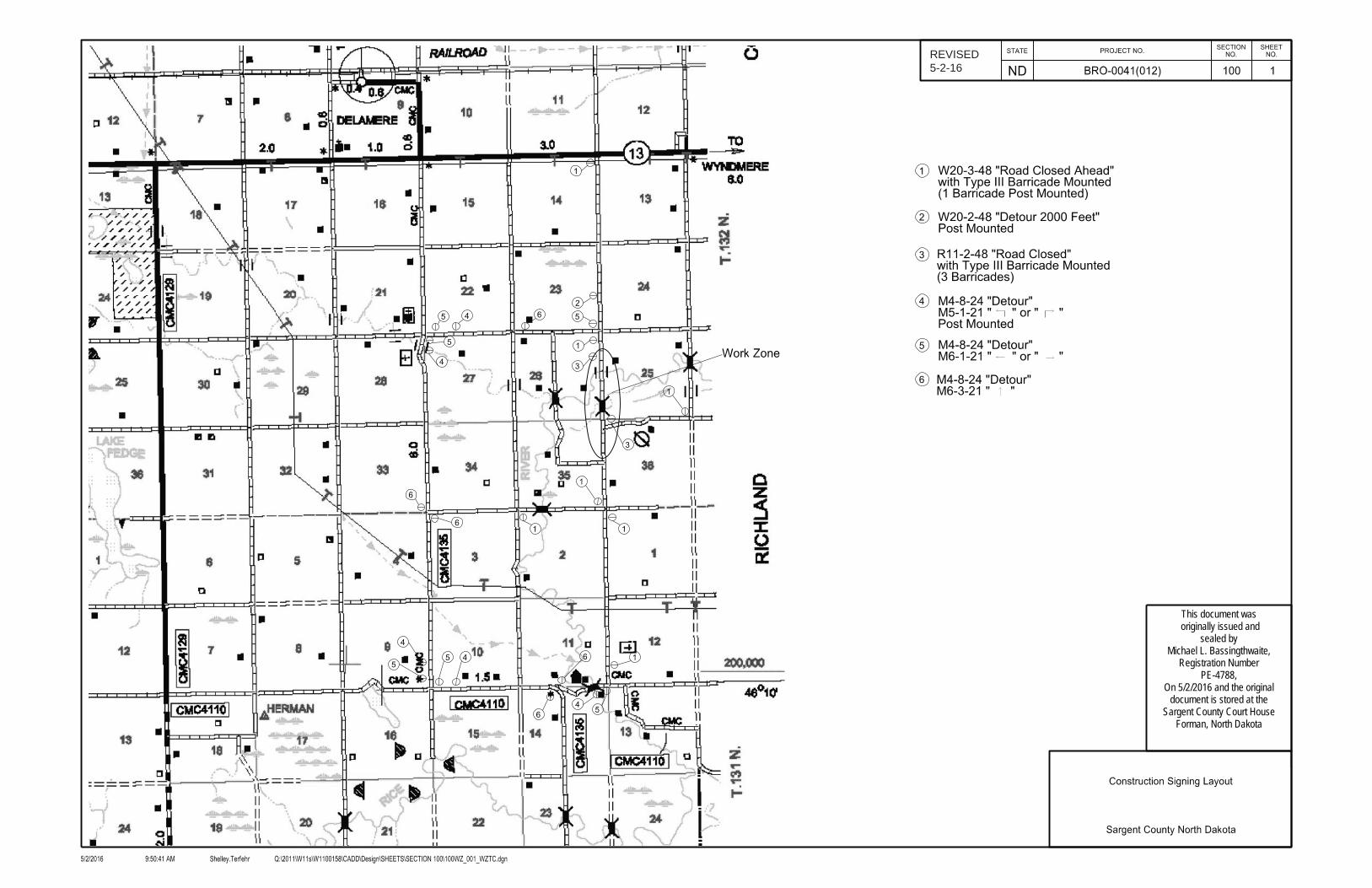
Three additional construction signs have been added to the project. 5. Remove and replace sheet 100-2 with the enclosed sheet revised 5/2/2016. The
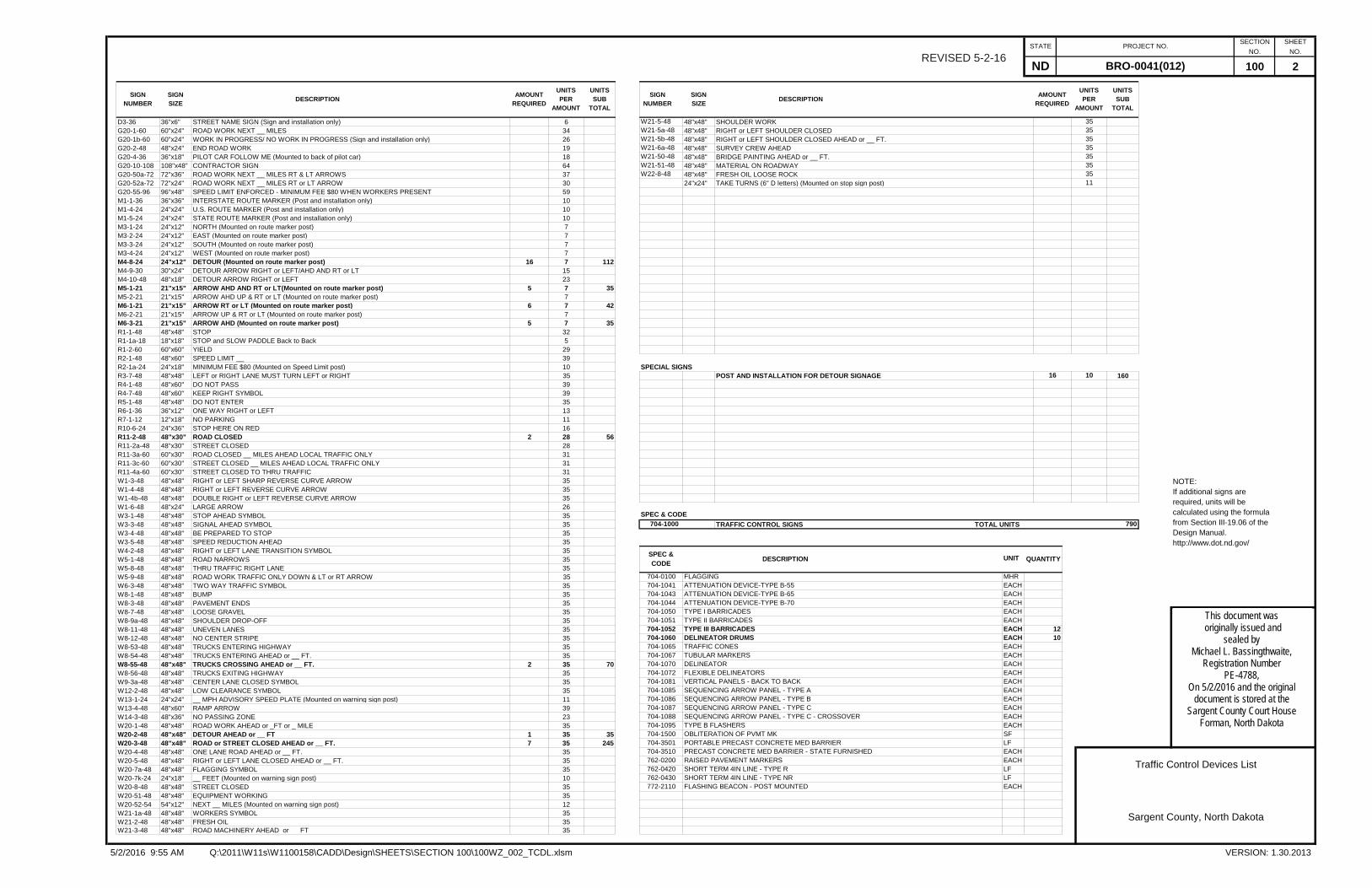
quantity of construction signs for the projects has been corrected and added to. 6. Remove and replace sheet 170-1 with the enclosed sheet revised 5/2/2016. Note
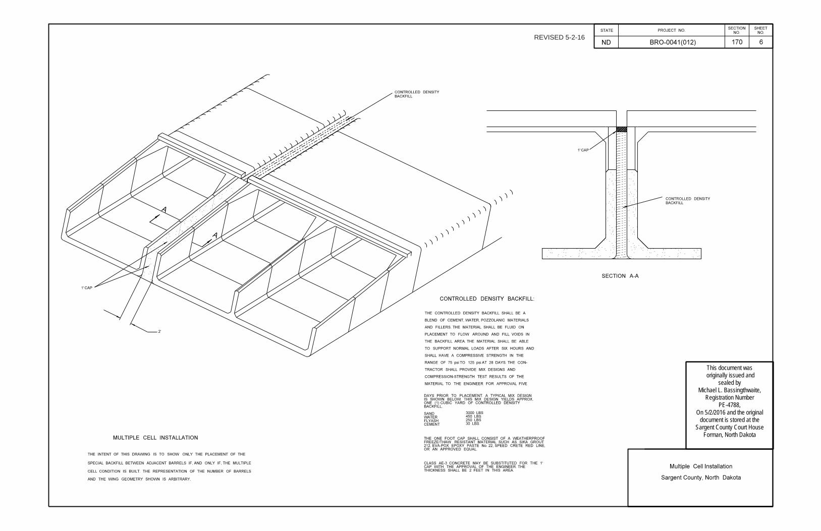
606-P01 has been revised. The contractor has been given the option of providing two lines of single cell box culvert in place of the previously specified double cell box culvert.
7. Add sheet 170-6 (enclosed) dated 5/2/2016 to the plan set. Requirements have been added for the two line of single cell box culvert option.
Proposal Revision: Remove and replace the SP 5112(14) placeholder with the enclosed SP 5112(14) dated 5/4/2016. The US Army Corp of Engineers 404 permit will be incorporated into the project by this SP. This addendum is to be incorporated into the bidder’s proposal for this project. Mike Bassingthwaite, PE MB:mb Enclosure
Mike Bassingthwaite
SpecNo.
Amount
Description UnitApprox.Quantity
Unit Price
$$$$$ 000 $$$$$ 00
PROPOSAL FORMNorth Dakota Department of Transportation
010Page 9 of 11
5/5/2016
JobMay 13, 2016BID OPENING:
CodeNo.
Bidder must type or neatly print unit prices in numerals, make extensions for each item, and total. Do not carry unit prices further than three (3) decimal places.
ItemNo.
Project: BRO-0041(012) (PCN-20039)
Rev: BID ITEMS
12FT X 11FT PRECAST RCB CULVERT 56.033 606 1211 LF
DBL 12FT X 11FT PRECAST RCB CULVERT 56.034 606 3211 LF
12FT X 11FT PRECAST RCB END SECTION 2.035 606 5211 EA
DBL 12FT X 11FT PRECAST RCB END SECTION 2.036 606 7211 EA
MOBILIZATION 1.037 702 0100 L SUM
TRAFFIC CONTROL SIGNS 790.038 704 1000 UNIT
TYPE III BARRICADE 12.039 704 1052 EA
DELINEATOR DRUMS 10.040 704 1060 EA
GEOSYNTHETIC MATERIAL TYPE R1 1,610.041 709 0151 SY
PIPE CORR STEEL .064IN 24IN 120.042 714 5035 LF
END SECT CORR STEEL .064IN 24IN 4.043 714 5820 EA
OBJECT MARKERS - CULVERTS 4.044 754 0805 EA
TEMPORARY STREAM DIVERSION 1.045 900 1000 EA
TOTAL SUM BID
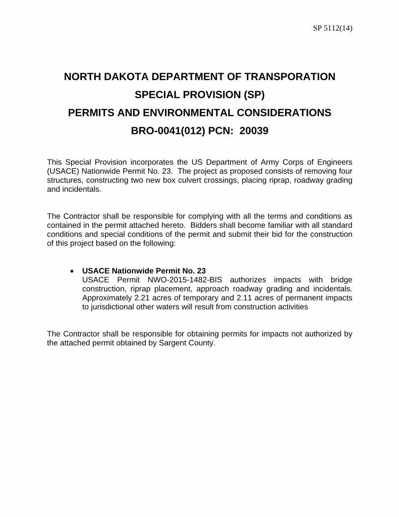
SP 5112(14)
NORTH DAKOTA DEPARTMENT OF TRANSPORATION
SPECIAL PROVISION (SP)
PERMITS AND ENVIRONMENTAL CONSIDERATIONS
BRO-0041(012) PCN: 20039
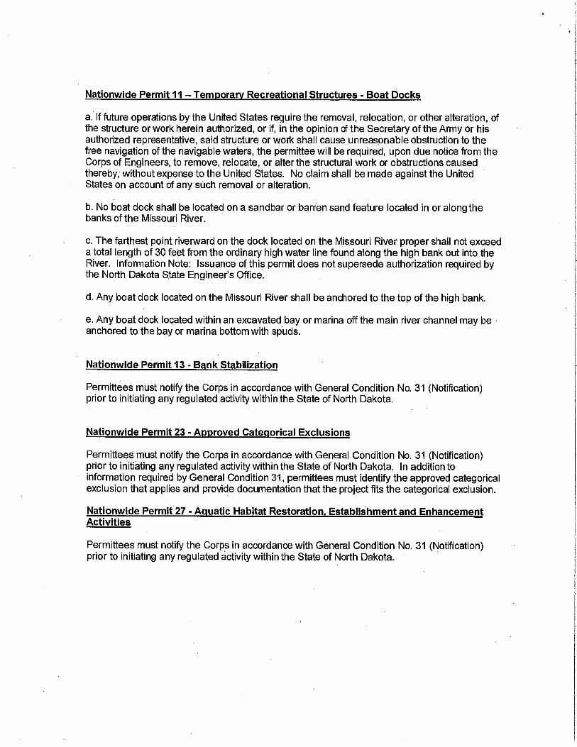
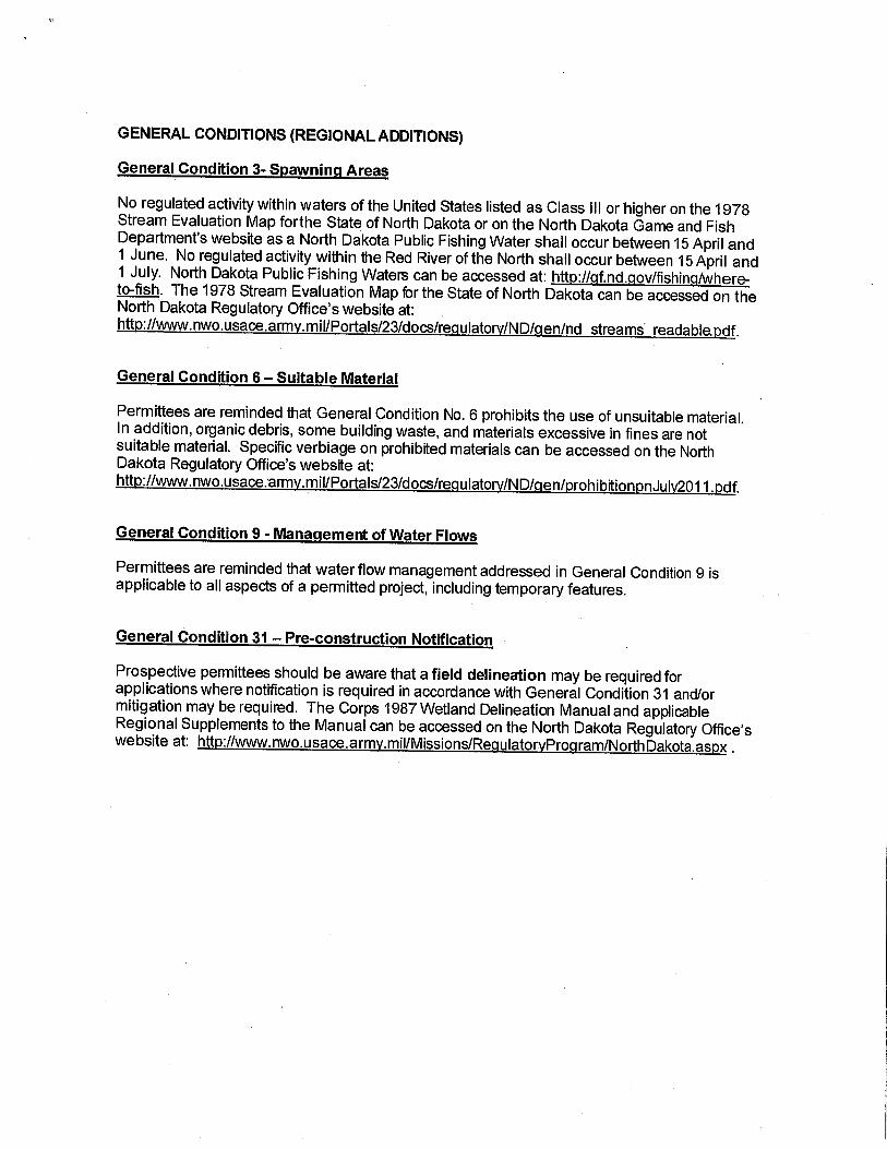
This Special Provision incorporates the US Department of Army Corps of Engineers (USACE) Nationwide Permit No. 23. The project as proposed consists of removing four structures, constructing two new box culvert crossings, placing riprap, roadway grading and incidentals. The Contractor shall be responsible for complying with all the terms and conditions as contained in the permit attached hereto. Bidders shall become familiar with all standard conditions and special conditions of the permit and submit their bid for the construction of this project based on the following:
USACE Nationwide Permit No. 23 USACE Permit NWO-2015-1482-BIS authorizes impacts with bridge construction, riprap placement, approach roadway grading and incidentals. Approximately 2.21 acres of temporary and 2.11 acres of permanent impacts to jurisdictional other waters will result from construction activities
The Contractor shall be responsible for obtaining permits for impacts not authorized by the attached permit obtained by Sargent County.
DEPARTMENT OF THE ARMY CORPS OF ENGINEERS, OMAHA DISTRICT
NORTH DAKOTA REGULATORY OFFICE 1513 SOUTH 12TH STREET BISMARCK ND 58504-6640
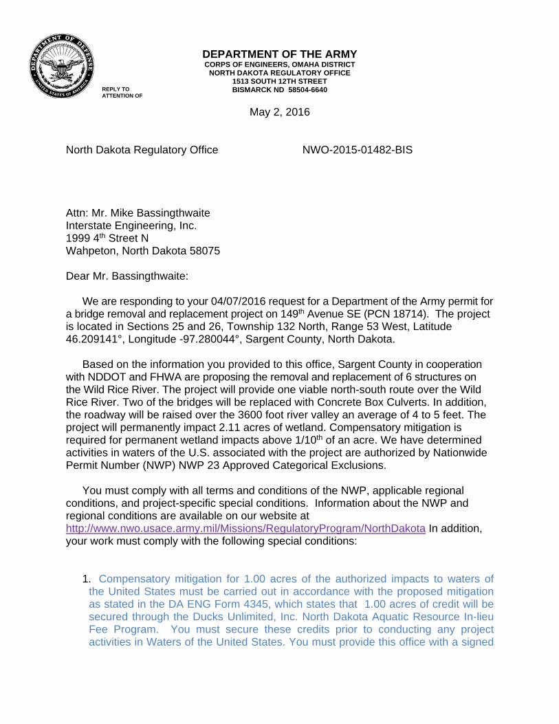
May 2, 2016
North Dakota Regulatory Office NWO-2015-01482-BIS
REPLY TO ATTENTION OF
Attn: Mr. Mike Bassingthwaite Interstate Engineering, Inc. 1999 4th Street N Wahpeton, North Dakota 58075 Dear Mr. Bassingthwaite:
We are responding to your 04/07/2016 request for a Department of the Army permit for a bridge removal and replacement project on 149th Avenue SE (PCN 18714). The project is located in Sections 25 and 26, Township 132 North, Range 53 West, Latitude 46.209141°, Longitude -97.280044°, Sargent County, North Dakota.
Based on the information you provided to this office, Sargent County in cooperation
with NDDOT and FHWA are proposing the removal and replacement of 6 structures on the Wild Rice River. The project will provide one viable north-south route over the Wild Rice River. Two of the bridges will be replaced with Concrete Box Culverts. In addition, the roadway will be raised over the 3600 foot river valley an average of 4 to 5 feet. The project will permanently impact 2.11 acres of wetland. Compensatory mitigation is required for permanent wetland impacts above 1/10th of an acre. We have determined activities in waters of the U.S. associated with the project are authorized by Nationwide Permit Number (NWP) NWP 23 Approved Categorical Exclusions.
You must comply with all terms and conditions of the NWP, applicable regional
conditions, and project-specific special conditions. Information about the NWP and regional conditions are available on our website at http://www.nwo.usace.army.mil/Missions/RegulatoryProgram/NorthDakota In addition, your work must comply with the following special conditions:
1. Compensatory mitigation for 1.00 acres of the authorized impacts to waters of
the United States must be carried out in accordance with the proposed mitigation as stated in the DA ENG Form 4345, which states that 1.00 acres of credit will be secured through the Ducks Unlimited, Inc. North Dakota Aquatic Resource In-lieu Fee Program. You must secure these credits prior to conducting any project activities in Waters of the United States. You must provide this office with a signed
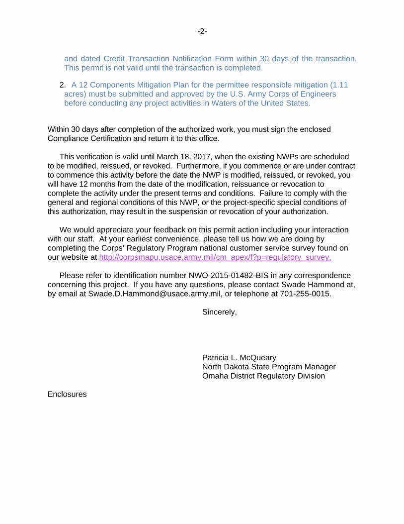
-2-
and dated Credit Transaction Notification Form within 30 days of the transaction. This permit is not valid until the transaction is completed.
2. A 12 Components Mitigation Plan for the permittee responsible mitigation (1.11 acres) must be submitted and approved by the U.S. Army Corps of Engineers before conducting any project activities in Waters of the United States.
Within 30 days after completion of the authorized work, you must sign the enclosed Compliance Certification and return it to this office.
This verification is valid until March 18, 2017, when the existing NWPs are scheduled
to be modified, reissued, or revoked. Furthermore, if you commence or are under contract to commence this activity before the date the NWP is modified, reissued, or revoked, you will have 12 months from the date of the modification, reissuance or revocation to complete the activity under the present terms and conditions. Failure to comply with the general and regional conditions of this NWP, or the project-specific special conditions of this authorization, may result in the suspension or revocation of your authorization.
We would appreciate your feedback on this permit action including your interaction
with our staff. At your earliest convenience, please tell us how we are doing by completing the Corps’ Regulatory Program national customer service survey found on our website at http://corpsmapu.usace.army.mil/cm_apex/f?p=regulatory_survey.
Please refer to identification number NWO-2015-01482-BIS in any correspondence
concerning this project. If you have any questions, please contact Swade Hammond at, by email at [email protected], or telephone at 701-255-0015.
Sincerely,
Patricia L. McQueary North Dakota State Program Manager Omaha District Regulatory Division
Enclosures
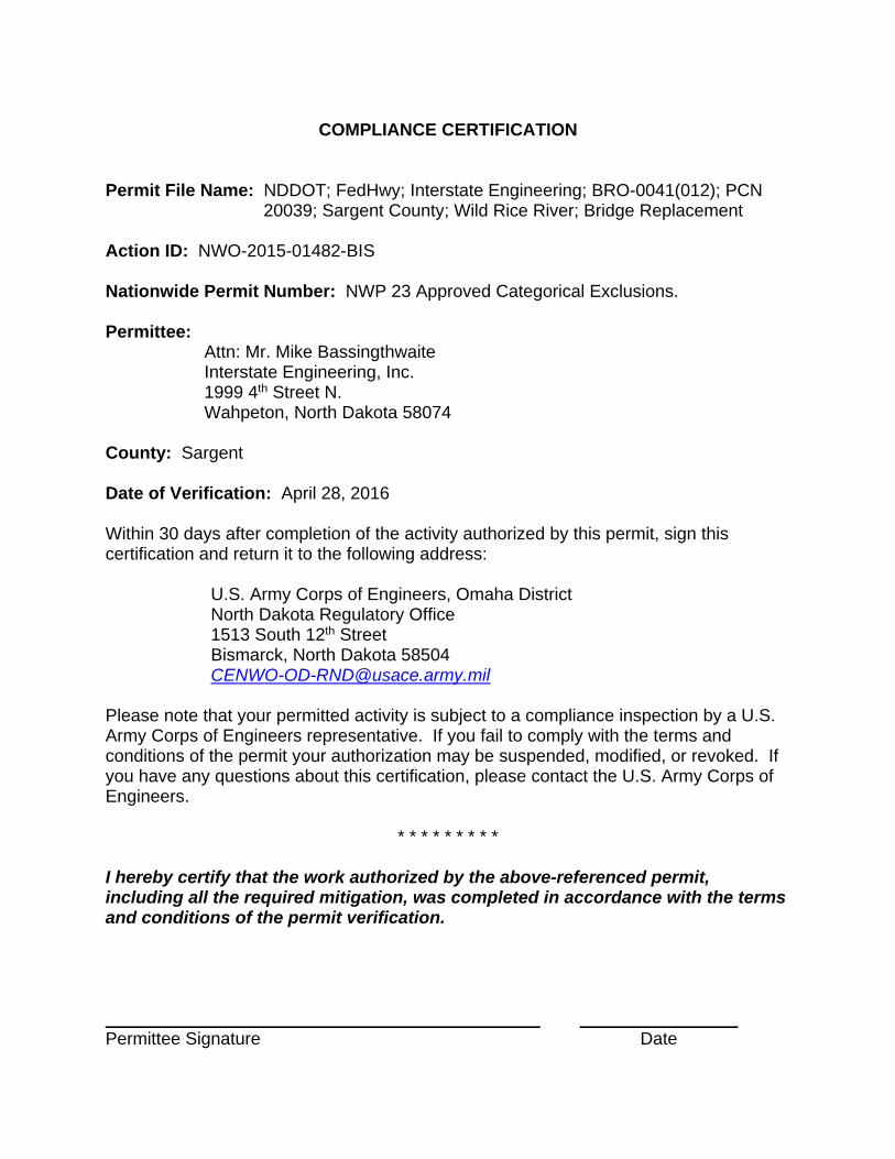
COMPLIANCE CERTIFICATION Permit File Name: NDDOT; FedHwy; Interstate Engineering; BRO-0041(012); PCN
20039; Sargent County; Wild Rice River; Bridge Replacement Action ID: NWO-2015-01482-BIS Nationwide Permit Number: NWP 23 Approved Categorical Exclusions. Permittee:
Attn: Mr. Mike Bassingthwaite Interstate Engineering, Inc. 1999 4th Street N. Wahpeton, North Dakota 58074
County: Sargent Date of Verification: April 28, 2016 Within 30 days after completion of the activity authorized by this permit, sign this certification and return it to the following address:
U.S. Army Corps of Engineers, Omaha District North Dakota Regulatory Office 1513 South 12th Street Bismarck, North Dakota 58504 [email protected]
Please note that your permitted activity is subject to a compliance inspection by a U.S. Army Corps of Engineers representative. If you fail to comply with the terms and conditions of the permit your authorization may be suspended, modified, or revoked. If you have any questions about this certification, please contact the U.S. Army Corps of Engineers.
* * * * * * * * * I hereby certify that the work authorized by the above-referenced permit, including all the required mitigation, was completed in accordance with the terms and conditions of the permit verification. Permittee Signature Date
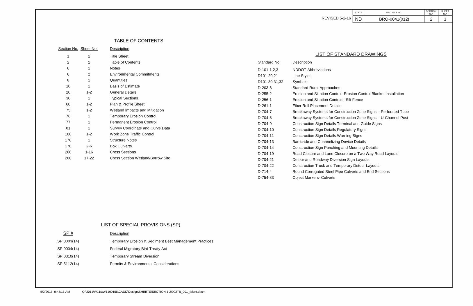
REVISED 5-2-16
5/2/2016 9:43:16 AM Q:\2011\W11s\W1100158\CADD\Design\SHEETS\SECTION 1-2\002TB_001_tblcnt.docm
STATE PROJECT NO.SECTION
NO.SHEET
NO.
ND BRO-0041(012) 2 1
TABLE OF CONTENTS
Section No. Sheet No. Description
1 1 Title Sheet
2 1 Table of Contents
6 1 Notes
6 2 Environmental Commitments
8 1 Quantities
10 1 Basis of Estimate
20 1-2 General Details
30 1 Typical Sections
60 1-2 Plan & Profile Sheet
75 1-2 Wetland Impacts and Mitigation
76 1 Temporary Erosion Control
77 1 Permanent Erosion Control
81 1 Survey Coordinate and Curve Data
100 1-2 Work Zone Traffic Control
170 1 Structure Notes
170 2-6 Box Culverts
200 1-16 Cross Sections
200 17-22 Cross Section Wetland/Borrow Site
LIST OF SPECIAL PROVISIONS (SP)
SP # Description
SP 0003(14) Temporary Erosion & Sediment Best Management Practices
SP 0004(14) Federal Migratory Bird Treaty Act
SP 0310(14) Temporary Stream Diversion
SP 5112(14) Permits & Environmental Considerations
LIST OF STANDARD DRAWINGS
Standard No. Description
D-101-1,2,3 NDDOT Abbreviations
D101-20,21 Line Styles
D101-30,31,32 Symbols
D-203-8 Standard Rural Approaches
D-255-2 Erosion and Siltation Control- Erosion Control Blanket Installation
D-256-1 Erosion and Siltation Controls- Silt Fence
D-261-1 Fiber Roll Placement Details
D-704-7 Breakaway Systems for Construction Zone Signs – Perforated Tube
D-704-8 Breakaway Systems for Construction Zone Signs – U-Channel Post
D-704-9 Construction Sign Details Terminal and Guide Signs
D-704-10 Construction Sign Details Regulatory Signs
D-704-11 Construction Sign Details Warning Signs
D-704-13 Barricade and Channelizing Device Details
D-704-14 Construction Sign Punching and Mounting Details
D-704-19 Road Closure and Lane Closure on a Two Way Road Layouts
D-704-21 Detour and Roadway Diversion Sign Layouts
D-704-22 Construction Truck and Temporary Detour Layouts
D-714-4 Round Corrugated Steel Pipe Culverts and End Sections
D-754-83 Object Markers- Culverts
REVISED 5-2-16
5/2/2016 9:41:50 AM Q:\2011\W11s\W1100158\CADD\Design\SHEETS\SECTION 8\Estimate.docm
STATE PROJECT NO.SECTION
NO.SHEET
NO.
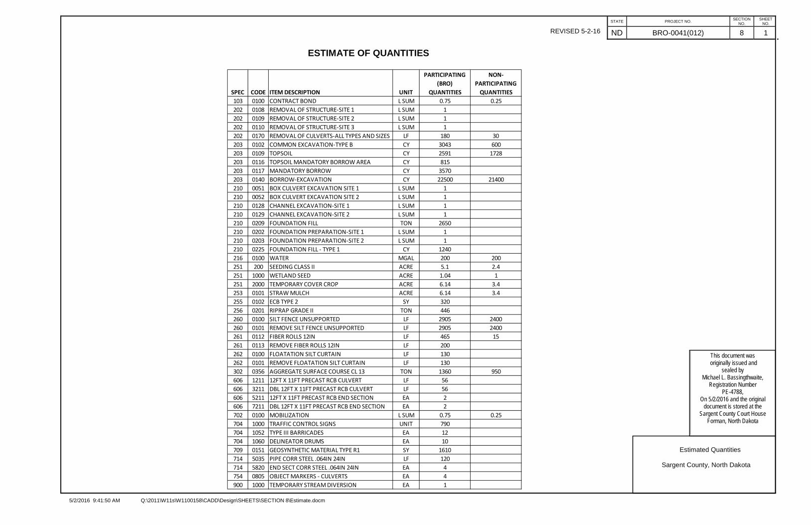
ND BRO-0041(012) 8 1
Estimated Quantities
Sargent County, North Dakota
ESTIMATE OF QUANTITIES
SPEC CODE ITEM DESCRIPTION UNIT
PARTICIPATING (BRO)
QUANTITIES
NON-PARTICIPATING
QUANTITIES103 0100 CONTRACT BOND L SUM 0.75 0.25202 0108 REMOVAL OF STRUCTURE-SITE 1 L SUM 1202 0109 REMOVAL OF STRUCTURE-SITE 2 L SUM 1202 0110 REMOVAL OF STRUCTURE-SITE 3 L SUM 1202 0170 REMOVAL OF CULVERTS-ALL TYPES AND SIZES LF 180 30203 0102 COMMON EXCAVATION-TYPE B CY 3043 600203 0109 TOPSOIL CY 2591 1728203 0116 TOPSOIL MANDATORY BORROW AREA CY 815203 0117 MANDATORY BORROW CY 3570203 0140 BORROW-EXCAVATION CY 22500 21400210 0051 BOX CULVERT EXCAVATION SITE 1 L SUM 1210 0052 BOX CULVERT EXCAVATION SITE 2 L SUM 1210 0128 CHANNEL EXCAVATION-SITE 1 L SUM 1210 0129 CHANNEL EXCAVATION-SITE 2 L SUM 1210 0209 FOUNDATION FILL TON 2650210 0202 FOUNDATION PREPARATION-SITE 1 L SUM 1210 0203 FOUNDATION PREPARATION-SITE 2 L SUM 1210 0225 FOUNDATION FILL - TYPE 1 CY 1240216 0100 WATER MGAL 200 200251 200 SEEDING CLASS II ACRE 5.1 2.4251 1000 WETLAND SEED ACRE 1.04 1251 2000 TEMPORARY COVER CROP ACRE 6.14 3.4253 0101 STRAW MULCH ACRE 6.14 3.4255 0102 ECB TYPE 2 SY 320256 0201 RIPRAP GRADE II TON 446260 0100 SILT FENCE UNSUPPORTED LF 2905 2400260 0101 REMOVE SILT FENCE UNSUPPORTED LF 2905 2400261 0112 FIBER ROLLS 12IN LF 465 15261 0113 REMOVE FIBER ROLLS 12IN LF 200262 0100 FLOATATION SILT CURTAIN LF 130262 0101 REMOVE FLOATATION SILT CURTAIN LF 130302 0356 AGGREGATE SURFACE COURSE CL 13 TON 1360 950606 1211 12FT X 11FT PRECAST RCB CULVERT LF 56606 3211 DBL 12FT X 11FT PRECAST RCB CULVERT LF 56606 5211 12FT X 11FT PRECAST RCB END SECTION EA 2606 7211 DBL 12FT X 11FT PRECAST RCB END SECTION EA 2702 0100 MOBILIZATION L SUM 0.75 0.25704 1000 TRAFFIC CONTROL SIGNS UNIT 790704 1052 TYPE III BARRICADES EA 12704 1060 DELINEATOR DRUMS EA 10709 0151 GEOSYNTHETIC MATERIAL TYPE R1 SY 1610714 5035 PIPE CORR STEEL .064IN 24IN LF 120714 5820 END SECT CORR STEEL .064IN 24IN EA 4754 0805 OBJECT MARKERS - CULVERTS EA 4900 1000 TEMPORARY STREAM DIVERSION EA 1
This document wasoriginally issued and
sealed byMichael L. Bassingthwaite,
Registration NumberPE-4788,
On 5/2/2016 and the original document is stored at the
Sargent County Court HouseForman, North Dakota
REVISED5-2-16
This document wasoriginally issued and
sealed byMichael L. Bassingthwaite,
Registration NumberPE-4788,
On 5/2/2016 and the original document is stored at the
Sargent County Court HouseForman, North Dakota
REVISED5-2-16
This document wasoriginally issued and
sealed byMichael L. Bassingthwaite,
Registration NumberPE-4788,
On 5/2/2016 and the original document is stored at the
Sargent County Court HouseForman, North Dakota
5/2/2016 9:55 AM Q:\2011\W11s\W1100158\CADD\Design\SHEETS\SECTION 100\100WZ_002_TCDL.xlsm VERSION: 1.30.2013
SECTION SHEET
NO. NO.
100 2
D3-36 36"x6" STREET NAME SIGN (Sign and installation only) 6 48"x48" SHOULDER WORKG20-1-60 60"x24" ROAD WORK NEXT __ MILES 34 48"x48" RIGHT or LEFT SHOULDER CLOSEDG20-1b-60 60"x24" WORK IN PROGRESS/ NO WORK IN PROGRESS (Sign and installation only) 26 48"x48" RIGHT or LEFT SHOULDER CLOSED AHEAD or __ FT.G20-2-48 48"x24" END ROAD WORK 19 48"x48" SURVEY CREW AHEADG20-4-36 36"x18" PILOT CAR FOLLOW ME (Mounted to back of pilot car) 18 48"x48" BRIDGE PAINTING AHEAD or __ FT.G20-10-108 108"x48" CONTRACTOR SIGN 64 48"x48" MATERIAL ON ROADWAYG20-50a-72 72"x36" ROAD WORK NEXT __ MILES RT & LT ARROWS 37 48"x48" FRESH OIL LOOSE ROCKG20-52a-72 72"x24" ROAD WORK NEXT __ MILES RT or LT ARROW 30 24"x24" TAKE TURNS (6" D letters) (Mounted on stop sign post)G20-55-96 96"x48" SPEED LIMIT ENFORCED - MINIMUM FEE $80 WHEN WORKERS PRESENT 59M1-1-36 36"x36" INTERSTATE ROUTE MARKER (Post and installation only) 10M1-4-24 24"x24" U.S. ROUTE MARKER (Post and installation only) 10M1-5-24 24"x24" STATE ROUTE MARKER (Post and installation only) 10M3-1-24 24"x12" NORTH (Mounted on route marker post) 7M3-2-24 24"x12" EAST (Mounted on route marker post) 7M3-3-24 24"x12" SOUTH (Mounted on route marker post) 7M3-4-24 24"x12" WEST (Mounted on route marker post) 7M4-8-24 24"x12" DETOUR (Mounted on route marker post) 16 7 112M4-9-30 30"x24" DETOUR ARROW RIGHT or LEFT/AHD AND RT or LT 15M4-10-48 48"x18" DETOUR ARROW RIGHT or LEFT 23M5-1-21 21"x15" ARROW AHD AND RT or LT(Mounted on route marker post) 5 7 35M5-2-21 21"x15" ARROW AHD UP & RT or LT (Mounted on route marker post) 7M6-1-21 21"x15" ARROW RT or LT (Mounted on route marker post) 6 7 42M6-2-21 21"x15" ARROW UP & RT or LT (Mounted on route marker post) 7M6-3-21 21"x15" ARROW AHD (Mounted on route marker post) 5 7 35R1-1-48 48"x48" STOP 32R1-1a-18 18"x18" STOP and SLOW PADDLE Back to Back 5R1-2-60 60"x60" YIELD 29R2-1-48 48"x60" SPEED LIMIT __ 39R2-1a-24 24"x18" MINIMUM FEE $80 (Mounted on Speed Limit post) 10 SPECIAL SIGNSR3-7-48 48"x48" LEFT or RIGHT LANE MUST TURN LEFT or RIGHT 35 POST AND INSTALLATION FOR DETOUR SIGNAGE 160R4-1-48 48"x60" DO NOT PASS 39R4-7-48 48"x60" KEEP RIGHT SYMBOL 39R5-1-48 48"x48" DO NOT ENTER 35R6-1-36 36"x12" ONE WAY RIGHT or LEFT 13R7-1-12 12"x18" NO PARKING 11R10-6-24 24"x36" STOP HERE ON RED 16R11-2-48 48"x30" ROAD CLOSED 2 28 56R11-2a-48 48"x30" STREET CLOSED 28R11-3a-60 60"x30" ROAD CLOSED __ MILES AHEAD LOCAL TRAFFIC ONLY 31R11-3c-60 60"x30" STREET CLOSED __ MILES AHEAD LOCAL TRAFFIC ONLY 31R11-4a-60 60"x30" STREET CLOSED TO THRU TRAFFIC 31W1-3-48 48"x48" RIGHT or LEFT SHARP REVERSE CURVE ARROW 35W1-4-48 48"x48" RIGHT or LEFT REVERSE CURVE ARROW 35W1-4b-48 48"x48" DOUBLE RIGHT or LEFT REVERSE CURVE ARROW 35W1-6-48 48"x24" LARGE ARROW 26W3-1-48 48"x48" STOP AHEAD SYMBOL 35W3-3-48 48"x48" SIGNAL AHEAD SYMBOL 35 TRAFFIC CONTROL SIGNS TOTAL UNITSW3-4-48 48"x48" BE PREPARED TO STOP 35W3-5-48 48"x48" SPEED REDUCTION AHEAD 35W4-2-48 48"x48" RIGHT or LEFT LANE TRANSITION SYMBOL 35W5-1-48 48"x48" ROAD NARROWS 35W5-8-48 48"x48" THRU TRAFFIC RIGHT LANE 35W5-9-48 48"x48" ROAD WORK TRAFFIC ONLY DOWN & LT or RT ARROW 35W6-3-48 48"x48" TWO WAY TRAFFIC SYMBOL 35W8-1-48 48"x48" BUMP 35W8-3-48 48"x48" PAVEMENT ENDS 35W8-7-48 48"x48" LOOSE GRAVEL 35W8-9a-48 48"x48" SHOULDER DROP-OFF 35W8-11-48 48"x48" UNEVEN LANES 35W8-12-48 48"x48" NO CENTER STRIPE 35W8-53-48 48"x48" TRUCKS ENTERING HIGHWAY 35W8-54-48 48"x48" TRUCKS ENTERING AHEAD or __ FT. 35W8-55-48 48"x48" TRUCKS CROSSING AHEAD or __ FT. 2 35 70W8-56-48 48"x48" TRUCKS EXITING HIGHWAY 35W9-3a-48 48"x48" CENTER LANE CLOSED SYMBOL 35W12-2-48 48"x48" LOW CLEARANCE SYMBOL 35W13-1-24 24"x24" __ MPH ADVISORY SPEED PLATE (Mounted on warning sign post) 11W13-4-48 48"x60" RAMP ARROW 39W14-3-48 48"x36" NO PASSING ZONE 23W20-1-48 48"x48" ROAD WORK AHEAD or _FT or _ MILE 35W20-2-48 48"x48" DETOUR AHEAD or __ FT 1 35 35W20-3-48 48"x48" ROAD or STREET CLOSED AHEAD or __ FT. 7 35 245W20-4-48 48"x48" ONE LANE ROAD AHEAD or __ FT. 35W20-5-48 48"x48" RIGHT or LEFT LANE CLOSED AHEAD or __ FT. 35W20-7a-48 48"x48" FLAGGING SYMBOL 35W20-7k-24 24"x18" __ FEET (Mounted on warning sign post) 10W20-8-48 48"x48" STREET CLOSED 35W20-51-48 48"x48" EQUIPMENT WORKING 35W20-52-54 54"x12" NEXT __ MILES (Mounted on warning sign post) 12W21-1a-48 48"x48" WORKERS SYMBOL 35W21-2-48 48"x48" FRESH OIL 35W21-3-48 48"x48" ROAD MACHINERY AHEAD or __ FT 35
UNITS SUB
TOTAL
16
Sargent County, North Dakota
12
Traffic Control Devices List
35
NOTE:If additional signs are required, units will be calculated using the formula from Section III-19.06 of the Design Manual.http://www.dot.nd.gov/
10
790
STATE
ND
PROJECT NO.
35
BRO-0041(012)
UNITS PER
AMOUNT
3511
35
AMOUNT REQUIRED
SIGN SIZE
W21-5-48
DESCRIPTION
353535
UNITS PER
AMOUNT
UNITS SUB
TOTAL
SIGN NUMBER
SIGN NUMBER
SIGN SIZE
DESCRIPTIONAMOUNT
REQUIRED
W21-5b-48W21-6a-48W21-50-48W21-51-48
W21-5a-48
W22-8-48
EACH
10EACHEACH
EACH
EACH
EACHEACHEACH
QUANTITY
704-1065704-1067704-1070704-1072
704-1087
VERTICAL PANELS - BACK TO BACK
EACHEACHEACH
EACH
EACH
EACHEACH
EACH
704-1044704-1043
ATTENUATION DEVICE-TYPE B-55
FLEXIBLE DELINEATORS
SHORT TERM 4IN LINE - TYPE NRFLASHING BEACON - POST MOUNTED
SFLFEACHEACHLF
EACHLF
SPEC & CODE
DESCRIPTION
FLAGGING704-0100 MHR
704-1000
SPEC & CODE
UNIT
TYPE I BARRICADESTYPE II BARRICADES
SEQUENCING ARROW PANEL - TYPE C - CROSSOVERTYPE B FLASHERSOBLITERATION OF PVMT MKPORTABLE PRECAST CONCRETE MED BARRIERPRECAST CONCRETE MED BARRIER - STATE FURNISHEDRAISED PAVEMENT MARKERSSHORT TERM 4IN LINE - TYPE R
704-1088704-1095704-1500704-3501
TUBULAR MARKERSDELINEATOR
762-0420
704-1060 DELINEATOR DRUMS
SEQUENCING ARROW PANEL - TYPE ASEQUENCING ARROW PANEL - TYPE BSEQUENCING ARROW PANEL - TYPE C
704-1041
TRAFFIC CONES
762-0430772-2110
ATTENUATION DEVICE-TYPE B-65ATTENUATION DEVICE-TYPE B-70
EACH
704-3510762-0200
704-1081704-1085704-1086
704-1050704-1051704-1052 TYPE III BARRICADES
REVISED 5-2-16
This document wasoriginally issued and
sealed byMichael L. Bassingthwaite,
Registration NumberPE-4788,
On 5/2/2016 and the original document is stored at the
Sargent County Court HouseForman, North Dakota
STRUCTURE NOTES
5/2/2016 11:16:59 AM Q:\2011\W11s\W1100158\CADD\Design\SHEETS\SECTION 170\BridgeNotes.docm
STATE PROJECT NO.SECTION
NO.SHEET
NO.
ND BRO-0041(012) 170 1
100-P01 SCOPE OF WORK: This project shall consist of the removal of 3 bridges and 1 large culvert crossing and the installation of RCB at 2 of the removal locations.
202-P01 REMOVAL OF STRUCTURE-SITE 1: The existing structure to be removed at this locationconsists of a single span concrete/steel girder bridge 29 feet in length. The existing roadway embankments have been washed away at this location. The contractor shall be responsible for access for the removal as part of this bid item.
REMOVAL OF STRUCTURE-SITE 2: The existing structure to be removed at this location consists of a single span timber bridge 28 feet in length.
REMOVAL OF STRUCTURE-SITE 3: The existing structure to be removed at this location consists of a single span timber bridge with steel piling 41 feet in length.
All salvaged materials will become property of the Contractor for all 3 removals. The Contractor shall arrange for and secure a suitable disposal site off of the right-of-way for the remainder of the structure. Any existing substructures shall be removed in accordance with Section 202.04B of the Standard Specifications.
Embankment is required for the barrier mound (see section 20 detail) and shall be obtained from the roadway fill excavation behind the existing abutments as directed by the Engineer. All natural grass and disturbed areas shall be seeded per section 251 of the standard specifications and plan notes. Road closure signing shall be as detailed in section 20. All signs, posts, and barricades shall be installed per section 704 of the standard specifications and relevant standard drawings.
All costs associated with removal and disposal of the structure shall be included in the price bid for “Removal of Structure-Site x”. These costs shall include removal, signing, barricades, posts, labor seeding, earthwork, etc.
202-P02 REMOVAL OF PIPES ALL TYPES AND SIZES: The existing pipes to be removed at Station 70+75 consist of three (3) 11ftx10in x7ftx7in SPPA’s 60 feet in length each. All salvaged materials will become property of the Contractor.
210-P01 BOX CULVERT EXCAVATION: Shall be to the limits shown on the plan typical box culvert layout drawings. All material not considered suitable for the roadbed shall be used to fill the road in-slopes unless the material is deemed waste excavation by the engineer. It is assumed that this material will be suitable for use in embankment areas. Payment for all Box Culvert Excavation to the limits shown on the plans will be Lump Sum. The price bid for Box Culvert Excavation shall include the costs for placement of this material in embankment areas. The embankment shall meet the requirements of Section 203.02H Compaction Control Type B.
210-P02 FOUNDATION FILL – TYPE 1: Foundation Fill – Type 1 shall consist of Concrete Course Aggregate Size 4 and shall be installed in the bottom 3 feet of the excavated area below the box culvert as shown in plans. This aggregate must be wrapped completely with Geosynthetic Material Type S1. The Geosynthetic Material Type S1 shall be included in the price bid for Foundation Fill – Type 1.
606-P01 PRECAST REINFORCED CONCRETE BOX CULVERTS: Tie all barrel sections together with galvanized tie-bolts. Each joint will require four tie bolts at the third points of the wall
height. Provide fence anchors for each end section. Anchors required on all four corners and shall be suitable for four strand barbed wire fence.
Double and single box culvert end sections shall include a reinforced concrete parapet on the top of the roof and a reinforced concrete cutoff wall below the floor. The parapet shall be one (1) foot by one (1) foot and as long as the barrel sections outside width. The cutoff wall shall be placed below the end of the end sections and shall be a minimum of one (1) foot thick, and three (3) feet, two (2) inches deep, and shall extend three (3) feet beyond both of the endsection’s outside walls. These items shall be included in the bid price of each end section.
The contractor may substitute two (2) lines of single cell 12’X11’ RCBC for the specified double cell RCBC. Any additional costs for this substitution such as additional excavation or backfill material’s shall be included in the price of the RCBC. The bid price for double cell RCBC and end sections shall be paid regardless of which option is utilized.
The design loading of the box culverts shall be HL-93 with the minimum fill heights shown in the plans. The design of single and double box culvert barrels shall be based on a 10” thick roof, 10” floor, and 8” walls and the following total factored moments and shears that would result from the application of the required loads:
FACTORED DESIGN MOMENTS (SINGLE) FACTORED DESIGN MOMENTS (DBL)Wall Moment Wall Moment
Top Corner -13.2 ft-lbs Top Corner -8.6 ft-lbsMid Height, +VE 6.52 ft-lbs Mid Height, + VE 6.51 ft-lbsMid Height, -VE -6.15 ft-lbs Mid Height, - VE -1.19 ft-lbsBottom Corner -13.06 ft-lbs Bottom Corner -10.38 ft-lbs
Roof Moments Roof MomentsCorner -11.31 ft-lbs Ext. Corner -10.67 ft-lbsMidspan 29.02 ft-lbs Midspan 28.08 ft-lbs
Interior Corner -24.97 ft-lbsFloor Moments
Corner -12.45 ft-lbs Floor MomentsMidspan 25.42 ft-lbs Ext. Corner -11.22 ft-lbs
Midspan 13.35 ft-lbsInt. Corner -19.99 ft-lbs
NOTES1. Moments are due to strength I limit state.2. Negative (-VE) moments at corners are computed at the intersection of the haunch and the uniform depth
member per AASHTO 27.7.4.53. Positive (+VE) moments cause tension at the inside face of the component. Negative (-VE) moments
cause tension on the outside face of the component.
709-P01 GEOSYNTHETIC MATERIAL TYPE R1: The contractor shall install one continuous piece of fabric to meet the required longitudinal length indicated in the plans. Transverse seaming may be done by overlap per the standard specification.
WORKING DRAWINGS: The contractor shall submit the following working drawings to the Engineer of Record: Precast RCB Culvert and End Sections
REVISED 5-2-16
This document wasoriginally issued and
sealed byMichael L. Bassingthwaite,
Registration NumberPE-4788,
On 5/2/2016 and the original document is stored at the
Sargent County Court HouseForman, North Dakota
REVISED 5-2-16
This document wasoriginally issued and
sealed byMichael L. Bassingthwaite,
Registration NumberPE-4788,
On 5/2/2016 and the original document is stored at the
Sargent County Court HouseForman, North Dakota