microwave photonic technologies for flexible...
TRANSCRIPT

All rights reserved, 2007, Thales Alenia SpaceEuropean Conference on Optical Communication, Sept. 2 0 – 24, 2009, Vienna, Austria
Microwave Photonic Technologies for Flexible Satellite Telecom Payloads
M. Sotom, B. Bénazet, A. Le Kernec , M. Maignan

All rights reserved, 2007, Thales Alenia Space24/09/2009
Page 2
European Conference on Optical Communication, Sept. 2 0 – 24, 2009, Vienna, Austria
Contents
� Introduction
� Telecom satellites and payloads
� Optical handling of microwave signals
■ Optical distribution of local oscillators
■ Optical frequency conversion
� Examples of Opto-microwave telecom payload
■ Flexible payload
■ Photonic antenna subsystems
� Conclusion

All rights reserved, 2007, Thales Alenia Space24/09/2009
Page 3
European Conference on Optical Communication, Sept. 2 0 – 24, 2009, Vienna, Austria
Introduction
What is a space system ?
� A Space System is composed of- a space segment: one or several satellites- a launcher- a ground segment: Mission and Satellite Control Center(s)
� The Satellite is composed of- a Payload which supports the functionalities of the mission
- a Platform which supports and operates the Payload (powering, pointing, thermal management, telemetry / telecommand …)
� The Telecom payload is composed of- antenna sub-system - repeater sub-system
What are the main challenges ?� Cost � Reliability : 15 years in orbit (130 000 hours)� Mass� Harsh space environment: thermal, vacuum,
radiation, vibration & shock (launch)

All rights reserved, 2007, Thales Alenia Space24/09/2009
Page 4
European Conference on Optical Communication, Sept. 2 0 – 24, 2009, Vienna, Austria
Conventional telecom missions
� Global (or a few) coverage
� Fixed routing from uplink to downlink
accesses
� Transparent RF payloads
■ Mostly C (6/4 GHz) , Ku (14/12 GHz)
bands
■ Capacity: some Gbps
■ “bent-pipe” repeater concept
■ Low noise amplification
■ Frequency conversion
■ Demultiplexing / Filtering
■ High-power amplification
7.5°
Telecom satellites & payloads

All rights reserved, 2007, Thales Alenia Space24/09/2009
Page 5
European Conference on Optical Communication, Sept. 2 0 – 24, 2009, Vienna, Austria
Future broadband telecom missions
� Evolution driven by Multimedia / IP
� interactivity in broadcast systems
� bidirectional links: gateways/users & users/users
� Bandwidth increase & lower “transmitted bit” cost
■ migration to Ka-band (30 GHz / 20 GHz)
� New generation of high-directivity, multi-beam
antennas
■ cellular coverage with frequency reuse
■ > 100 spots for global coverage
� Flexible payloads required
■ on-board switching for flexible beam-to-beam
connectivity
■ versatile and transparent solutions (15-years) 0.4 – 0.6°
Telecom satellites & payloads

All rights reserved, 2007, Thales Alenia Space24/09/2009
Page 6
European Conference on Optical Communication, Sept. 2 0 – 24, 2009, Vienna, Austria
Future broadband telecom payloads
� flexible, complex payloads : coverage, connectivity, frequency plan, bandwidth allocation …
� > 100 RF channels (10’s of MHz) over 10’s of antenna beams
� critical requirements in terms of mass, volume & power consumption
� future-proof solutions = transparent payloads (analogue or digital)
HPALNA
Reference/ Master LO/ Synt. LO
Analogue payload
Analogue Processor
(filters&
switches)
30/IF DoCon IF/20 UpCon ADC HPALNA
Digital payload
Digital Signal
Processor 30/IF DoCon IF/20 UpConDAC
Reference/ Master LO/ Synt. LO
Telecom satellites & payloads
All rights reserved, 2007, Thales Alenia Space24/09/2009
Page 7
European Conference on Optical Communication, Sept. 2 0 – 24, 2009, Vienna, Austria
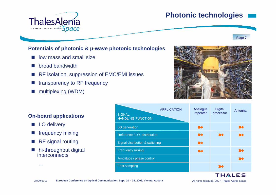
➼
Analogue repeater
AntennaDigital processor
➼
➼
APPLICATION
SIGNAL HANDLING FUNCTION
Reference / LO distribution
Frequency mixing
Fast sampling
Amplitude / phase control
➼
➼ ➼
➼
LO generation ➼
➼Signal distribution & switching
➼
Photonic technologies
Potentials of photonic & µ-wave photonic technologies
� low mass and small size
� broad bandwidth
� RF isolation, suppression of EMC/EMI issues
� transparency to RF frequency
� multiplexing (WDM)
On-board applications
� LO delivery
� frequency mixing
� RF signal routing
� hi-throughput digital interconnects
…

All rights reserved, 2007, Thales Alenia Space24/09/2009
Page 8
European Conference on Optical Communication, Sept. 2 0 – 24, 2009, Vienna, Austria
Optical LO distribution
� optical LO source
■ SC laser modulation (MHz to GHz)
■ laser + EO modulator @ high frequency
� SMF splitters, tree-like optical network
Applications : all (analogue/digital) payloads� mass savings, small size
� RF isolation, EMI free
� broad bandwidth, scalability …
Major achievements
� Optical distribution of USRO @ 10 MHz and MLO @ 800 MHz
� LO optical generation & distribution @ > 20GHz Double Side-Band with Carrier Suppression (DSB-CS)
RF in RF out
x N
LO
UpCon BB/IF UpCon
x N
LODigital processor
DoCon DoCon IF/BB
USROUSRO MLOMLO
splitter splittersplitter splitter
Microwave photonic building blocks
20 GHz20 GHz 30 GHz 40 GHz20 GHz20 GHz 30 GHz 40 GHz
Microwave input Optical outputMicrowave input Optical output

All rights reserved, 2007, Thales Alenia Space24/09/2009
Page 9
European Conference on Optical Communication, Sept. 2 0 – 24, 2009, Vienna, Austria
Photonic RF frequency mixing
� based on mixing properties of Mach-Zehnder Electro-Optical Modulator
� together with bandpass O/E Rx, centred @ IF
� demonstrated with high IF/LO & IF/RF isolation
� RF gain & NF ~ compatible with overall design > low-drive, low-loss EO modulator
ω IF = ω RF - ω LOEOM EOM ω RF
ω LO
O/E O/E
PhotonicLO
EOM : electro-optical mixerO/E : opto-electronic receiver
-25 dBc< -30 dBc
LORF
IF
-25 dBc< -30 dBc
LORF
IF
Microwave photonic building blocks

All rights reserved, 2007, Thales Alenia Space24/09/2009
Page 10
European Conference on Optical Communication, Sept. 2 0 – 24, 2009, Vienna, Austria
MWP repeater concept (ESA project)
� RF amplification and filtering
� optical distribution of centralised LO’s
� optical (multiple) frequency-conversion
� optical X-connection of µ-wave channels
Merits
� flexible beam-to-beam connectivity
� broadband, frequency-independent design
� scalable to large sizes
� low mass & volume, power consumption
Flexible MW photonic repeater
LNA EOM
O/E
O/EO/E
O/E
O/E
O/E
HPA
Rx section Tx section
Rx
ante
nnas
Tx
ante
nnas
LNA : low-noise amplifierEOM : electro-optical mixerHPA : high-power amplifierLO LO
Multiple optical LO ’s
OpticalCrossconnect

All rights reserved, 2007, Thales Alenia Space24/09/2009
Page 11
European Conference on Optical Communication, Sept. 2 0 – 24, 2009, Vienna, Austria
Breadboard repeater demonstrator (ESA project)
� sub-populated, yet representative of full-scale repeater
system
� Ka-band (30 to 4 GHz)
Flexible MW photonic repeater
➀ Microwave Photonic LO source
➁ Photonic frequency-mixer
➂ 4x4 MEMS-based optical cross-connect
➃ Microwave opto-electronic receivers

All rights reserved, 2007, Thales Alenia Space24/09/2009
Page 12
European Conference on Optical Communication, Sept. 2 0 – 24, 2009, Vienna, Austria
Large, 3D Optical MEMS switches (ESA project)� partnership with SERCALO (CH) : to develop a 50x50 switch demo
� array of I/O fibres and collimators, array of (MEMS) micro-mirrors with 3D steering� complexity grows as 2.N, can grow to large scales (> 100x100)� configurable as asymmetric matrices
Flexible MW photonic repeater

All rights reserved, 2007, Thales Alenia Space24/09/2009
Page 13
European Conference on Optical Communication, Sept. 2 0 – 24, 2009, Vienna, Austria
Optical Multi-frequency Conversion (OMC) (ESA project)
� Wavelength-Division Multiplexing (WDM)
of multiple microwave photonic LO’s
� mixing an RF signal with multiple LO’s
in electro-optical modulator
� wavelength de-multiplexing
� conversion to multiple IF signals
� applications to payload sub-systems
■ routing w/ frequency-slot interchange
■ routing w/ frequency band interchange
■ sub-band demultipexing
IF1 IF2 IF3
3 LO2 LO1
RFIF1 IF2
LO LO2 LO1
RFIF1 IF2 IF3
3 LO2 LO1
RFIF1 IF2
LO LO2 LO1
RF
Flexible MW photonic repeater
LNA : low-noise amplifierEOM : electro-optical mixerLO : local oscillatorWDM : wavelength (de)multiplexerO/E : optoelectronic receiver
O/EO/ELNA
LO3LO1 LO2
ωIF1 = ωRF – ωLO1
ωRF
ωLO1
O/EO/E
O/EO/E
ωIF2 = ωRF – ωLO2
ωIF3 = ωRF – ωLO3
EOM
ωLO2 ωLO3
W D M
WDM

All rights reserved, 2007, Thales Alenia Space24/09/2009
Page 14
European Conference on Optical Communication, Sept. 2 0 – 24, 2009, Vienna, Austria
Optical Multi-frequency Conversion (ESA project)
� Ka (30 GHz) to C (4 GHz) down-conversion
� with 2 LO’s, respectively @ 26.00 and 26.04 GHz
� conversion to 2 IF signals with frequency shift
� > 70 dB isolation between IF1 & IF2 signals
� no unwanted mixing products
IF2 @ 3.96 GHzIF1 @ 4 GHz
2nm ~ 250GHz2nm ~ 250GHz
Flexible MW photonic repeater

All rights reserved, 2007, Thales Alenia Space24/09/2009
Page 15
European Conference on Optical Communication, Sept. 2 0 – 24, 2009, Vienna, Austria
Microwave photonic front-end for advanced antennas (CNES project)
� optical LO distribution � frequency-conversion and IF remoting
Applications to multibeam receive antenna
� e.g. FAFR receive antenna� with Digital Beam-Forming
� critical requirements on size, mass and dissipation at the antenna element
Major achievements
� Optical front-end architecture study■ optical LO distribution @ 29 GHz■ Ka/L frequency down-conversion
■ optical receiver with ADC� Proof-of-concept & performance
assessment
LNA
Optical LO generation & distribution
EOM
EOM : electro-optical mixerO/E : opto-electronic detectorADC : Analogue to digital
converter
O/E O/E ADC
O/E O/E ADC
Digital Beam-forming
Processor
LNA
Optical LO generation & distribution
EOM
EOM : electro-optical mixerO/E : opto-electronic detectorADC : Analogue to digital
converter
O/E O/E ADC
O/E O/E ADC
Digital Beam-forming
Processor
Optical MixerLO
block
LO ControlMixer Control
MW photonic antenna sub-systems

All rights reserved, 2007, Thales Alenia Space24/09/2009
Page 16
European Conference on Optical Communication, Sept. 2 0 – 24, 2009, Vienna, Austria
Conclusions
Photonic and µ-wave photonic technologies in future telecom payloads
� for enhancing conventional implementations (mass, density, isolation …)
� as enabling technologies for advanced subsystem concepts
Photonic and µ-wave photonic building blocks
� optical distribution of reference / master oscillators
� optical generation & distribution of high frequency LO’s
� optical frequency-conversion
� optical distribution cross-connection of µW signals
� high throughput digital interconnects...
Proof-of concept demos have confirmed feasibility of sub-systems and proved good RF performance
Further work to improve performance AND integration , bring techn ology to higher maturity level, and prepare validation in on-orbit technology demos

All rights reserved, 2007, Thales Alenia Space24/09/2009
Page 17
European Conference on Optical Communication, Sept. 2 0 – 24, 2009, Vienna, Austria
Acknowledgements
� These works have been performed in the frame of ESA ARTES 5 projectsand CNES projects
� The authors would like to thank their partners of these projects
� The authors would like to thank the European Space Agency and the French Space Agency (CNES) for their support during these projects
THANK YOU