microstructural evolution and mechanical properties of inconel 625 alloy during pulsed plasma arc...
TRANSCRIPT

Available online at SciVerse ScienceDirect
J. Mater. Sci. Technol., 2013, 29(5), 480e488
Microstructural Evolution and Mechanical Properties of Inconel 625 Alloy
during Pulsed Plasma Arc Deposition Process
Fujia Xu1,2), Yaohui Lv2), Yuxin Liu2), Fengyuan Shu1,2), Peng He1)*, Binshi Xu1,2)
1) State Key Laboratory of Advanced Welding and Joining, Harbin Institute of Technology, Harbin 150001, China2) National Key Laboratory for Remanufacturing, Academy of Armored Forces Engineering, Beijing 100072, China
[Manuscript received March 24, 2012, in revised form October 22, 2012, Available online 15 February 2013]
* CorresE-mail a1005-03JournalLimited.http://dx
Pulsed plasma arc deposition (PPAD), which combines pulsed plasma cladding with rapid prototyping, is apromising technology for manufacturing near net shape components due to its superiority in cost andconvenience of processing. In the present research, PPAD was successfully used to fabricate the Ni-basedsuperalloy Inconel 625 components. The microstructures and mechanical properties of deposits wereinvestigated by scanning electron microscopy (SEM), optical microscopy (OM), transmission electronmicroscopy (TEM) with energy dispersive spectrometer (EDS), microhardness and tensile testers. It was foundthat the as-deposited structure exhibited homogenous columnar dendrite structure, which grew epitaxiallyalong the deposition direction. Moreover, some intermetallic phases such as Laves phase, minor MC (NbC,TiC) carbides and needle-like d-Ni3Nb were observed in g-Ni matrix. Precipitation mechanism and distributioncharacteristics of these intermetallic phases in the as-deposited 625 alloy sample were analyzed. In order toevaluate the mechanical properties of the deposits, microhardness was measured at various location(including transverse plane and longitudinal plane). The results revealed hardness was in the range of 260e285 HV0.2. In particular, microhardness at the interface region between two adjacent deposited layers wasslightly higher than that at other regions due to highly refined structure and the disperse distribution of Lavesparticles. Finally, the influence of precipitation phases and fabrication strategies on the tensile properties ofthe as-deposited samples was investigated. The failure modes of the tensile specimens were analyzed withfractography.
KEY WORDS: Pulsed plasma arc deposition; Inconel 625 components; Microstructure; Mechanical properties
1. Introduction
Ni-based superalloy Inconel 625 is widely applied in aero-nautical, aerospace, chemical, petrochemical and marine in-dustries. This material has a good combination of yield strength,tensile strength, creep strength, excellent process ability, weld-ability and good resistance to high temperature corrosion onprolonged exposure to aggressive environments[1e5]. Theseexcellent mechanical properties of Inconel 625 mainly dependupon the solid-solution hardening effect of the refractory metals,such as niobium and molybdenum in the nickelechromiummatrix[6,7]. Precipitation hardening in this alloy is mainly derivedfrom the precipitation of fine metastable phase g00-Ni3Nb after
ponding author. Prof., Ph.D.; Tel./Fax: þ86 451 86418746;ddress: [email protected] (P. He).02/$e see front matter Copyright� 2013, The editorial office ofof Materials Science & Technology. Published by ElsevierAll rights reserved..doi.org/10.1016/j.jmst.2013.02.010
annealing over a long period at 550e850 �C[8]. Moreover,various carbides including MC, M6C and M23C6 can also pre-cipitate during aging upon the time and temperature[9e11].However, many of the Inconel 625 components have highlycomplex shapes so that they are very expensive to be fabricateddue to extensive machining. Therefore, direct metal deposition(DMD) techniques for Inconel 625 components have receivedmore and more attentions in recent years. Among these tech-niques, the laser rapid manufacturing for Inconel 625 compo-nents has the most extensive applications. It is an emergingcomputer-aided manufacturing technology that uses a laserbeam to melt and deposit the filler material to form components,directly from computer-aided design (CAD) model. So far, aseries of manufacturing processes, which are similar to laserrapid manufacturing (LRM) have been developed with differentnames at various laboratories, such as laser engineering netshaping (LENS)[12], direct light fabrication (DLF)[13] and lasermetal forming (LMF)[14]. The merits of these manufacturingprocesses using laser as the heat source are that the heat-affectedzone and residual stresses are reduced and thus a lower part

Fig. 1 Schematic representation of the PPAD deposited process.
F. Xu et al.: J. Mater. Sci. Technol., 2013, 29(5), 480e488 481
distortion and better mechanical properties are achieved. Manystudies have been conducted on the microstructure and me-chanical properties of Inconel 625 components formed by laserrapid prototyping. Paul et al.[15] investigated the influenceof processing parameters during LRM of Inconel 625, andexplored the mechanical properties of test specimens. Their mainconclusion was that optimization of parameters could improvemechanical properties. Dinda et al.[16] studied the microstructureand properties of Inconel 625 samples fabricated by DMD pro-cess, and evaluated the thermal stability of structure at 800e1200 �C. The results indicated that as-deposited microstructuremostly consisted of columnar dendrites, which were stable up to1000 �C, and the precipitation of metastable g00-Ni3Nb resultedin the increase of microhardness[16]. However, there exist dis-advantages such as low deposition rates, huge production de-vices and high production cost in the laser rapid prototyping forInconel 625 components. Hence, laser rapid prototyping isespecially suitable for repairing or fabricating high-value partswith low production volume.Pulsed plasma arc deposition (PPAD) as a conventional
forming technique has many advantages of high production ef-ficiency, low cost, fine microstructure, excellent mechanicalproperties, and high density. Hence, the process is ideally suitedfor high volume manufacturing, particularly for the fabricationand repair of a variety of medium to large sized highly complexcomponents. Recently, it has been reported that plasma trans-ferred arc-assisted deposition technology can be also used todirectly manufacture a real component[17]. Zhao and Liu[18]
deposited a GH163 superalloy component by using this tech-nique, and investigated the effects of solid solution and agingtreatments on the microstructure characteristics of as-depositedsamples. However, little work has been done on the precipita-tion mechanism and distribution characteristics of intermetallic
Fig. 2 Diagrammatic sketches of raster patter
phases and their effects on mechanical properties of as-deposited625 alloys manufactured by PPAD.In the present paper, the microstructure and composition
segregation of Inconel 625 samples prepared by PPAD wereexplored. The precipitation mechanism and distribution charac-teristics of intermetallic phases in as-deposited 625 alloys werestudied. The effects of precipitation phases and fabricationstrategies on mechanical properties of deposits were alsoinvestigated.
2. Experimental
The forming of Inconel 625 components were carried out byPPAD system, which consists of plasma arc welding source,welding torch, wire feeding device, integrated with weldingrobot, water-cooled system and computer control system.Commercially available, Inconel 625 welding wire (ERNiCrMo-3) with 1.2 mm in diameter was used as filler metal. The averagechemical composition of the welding wire was 64.24 Ni, 22.65Cr, 8.73 Mo, 3.53 Nb, 0.01 C, 0.16 Al and 0.2 Ti (in wt%). Fig. 1presents the principle of PPAD technology. In the forming pro-cess, Inconel 625 welding wire was filled into a molten poolcreated by pulsed plasma arc, and rapidly solidified onto theprevious layer. By adding successive layers, three-dimensionalcomponents free of cracks and porosity were formed. Twokinds of Inconel 625 components were deposited on the lowcarbon steel sheet substrate to investigate the effects of fabrica-tion strategies on mechanical properties. The scan direction ofeach layer is opposite to that of previous deposited layer asshown in Fig. 2. The processing parameters of PPAD are listed inTable 1. The deposited sample with the dimension of 100 mm(length) � 40 mm (width) � 18 mm (height) carried about 15deposited layers.After the Inconel 625 components were fabricated by PPAD,
the microstructures and composition distribution of as-depositedsamples fabricated with short raster were examined by using aPhilips Quant 200 scanning electron microscope equipped withenergy dispersive spectrometer (EDS) apparatus and OLYMPUSoptical microscope. The precipitation phases and their crystalstructures were determined by means of transmission electronmicrocopy (TEM). The samples for scanning electron micro-scopy (SEM) observation were first mechanically polished tomirror finish and then chemically etched in a water solution of10% CrO3 for 5e10 s by using 304 L stainless steel sheet aselectrode. The microhardness of the deposited samples wasmeasured by a Vickers microhardness tester (HXZ-1000) using a1.96 N (200 gf) load for a dwell time of 15 s.
ns including long (a) and short (b) raster.

Table 1 Processing parameters of pulsed plasma arc deposition
Parameters Parameters value
Plasma gas flow (L/min) 0.3Shield gas flow (L/min) 15Peak current, IP (A) 230
Background current, Ib (A) 150Duty cycle 50%
Welding speed (m/min) 1.3Wire feed rate (m/min) 0.18
482 F. Xu et al.: J. Mater. Sci. Technol., 2013, 29(5), 480e488
The effect of raster pattern on tensile strength was investi-gated. In the tensile test process, specimens deposited with longraster pattern were tested in such a way that tensile loading axiswas parallel to the raster direction; while specimens depositedwith short raster pattern were tested in such a way that tensileloading axis was perpendicular to the raster direction. Mean-while, the uniformity of tensile strength for the same sample wasstudied. In addition, the fracture surface morphologies wereobserved with a Philips Quant 200 scanning electronmicroscope.
3. Results and Discussion
3.1. Microstructure characterization
Fig. 3 presents the as-deposited microstructure in a cross-section vertical to the plasma arc scanning direction. The stag-gered individual deposited tracks can be observed from the lowmagnification microscopy, as shown in Fig. 3(a). Fig. 3(b) showsthat bottom microstructure of the sample is mostly a finecolumnar dendritic structure with no secondary dendrites. It canbe seen that columnar dendrites grow epitaxially along the
Fig. 3 Macrostructure (a) and highly magnified microstructures at botto
deposition direction. During the PPAD process, the heat flowdirection of the solidification of molten pool is about perpen-dicular to the surface of substrate or the pre-deposited layers,leading to the growth of directional columnar dendrites. Fig. 3(c)highlights the microstructure of the overlapping interface be-tween two adjacent deposited tracks or layers. It can be observedthat a quite fine dendrite structure appears at the interface region.The dendrites at the two sides of interface exhibit almost thesame crystallographic orientation, which indicates a good con-sistency in crystal growth between different layers. Comparedwith the bottom microstructure, the microstructure for the upperpart of the sample exhibits a slightly coarse columnar dendriticstructure with classical secondary dendrite arms as shown inFig. 3(d). As described previously, the structure morphology ofthe as-deposited sample varies at different location of sampledepending upon the cooling rate of the melt pool in the PPADprocess. When bottom material of the sample is deposited, thesolidification velocity is very fast resulting from the water-cooledcopper plate, leading to fine primary dendrites without secondarydendrites. However, for the upper part of the sample, the tem-perature gradient becomes small, and the cooling rate becomeslow as a result of the heat accumulation. Therefore, the primarydendrites become slightly coarse, and the secondary dendrite armspacing at the upper part of the sample varies between 20 and25 mm, as shown in Fig. 3(d).Fig. 4 demonstrates a typical SEM image of the major phases
appearing in the deposits. It can be observed that some smalldark particles in globular, a large number of irregular shapes andneedle-like phases were precipitated in the interdendritic regions.TEM observations and EDS X-ray microanalysis were carriedout to clarify these precipitated phases in the as-depositedmicrostructure. Fig. 5(a) shows the precipitation of A2B typeLaves phase in irregular shape, which has a close-packed hex-agonal structure. The inset in Fig. 5(a) presents the SAD patternof Laves phase with a [011] zone axis. Moreover, it can be
m (b) and upper part (c, d) of the as-deposited Inconel 625 sample.
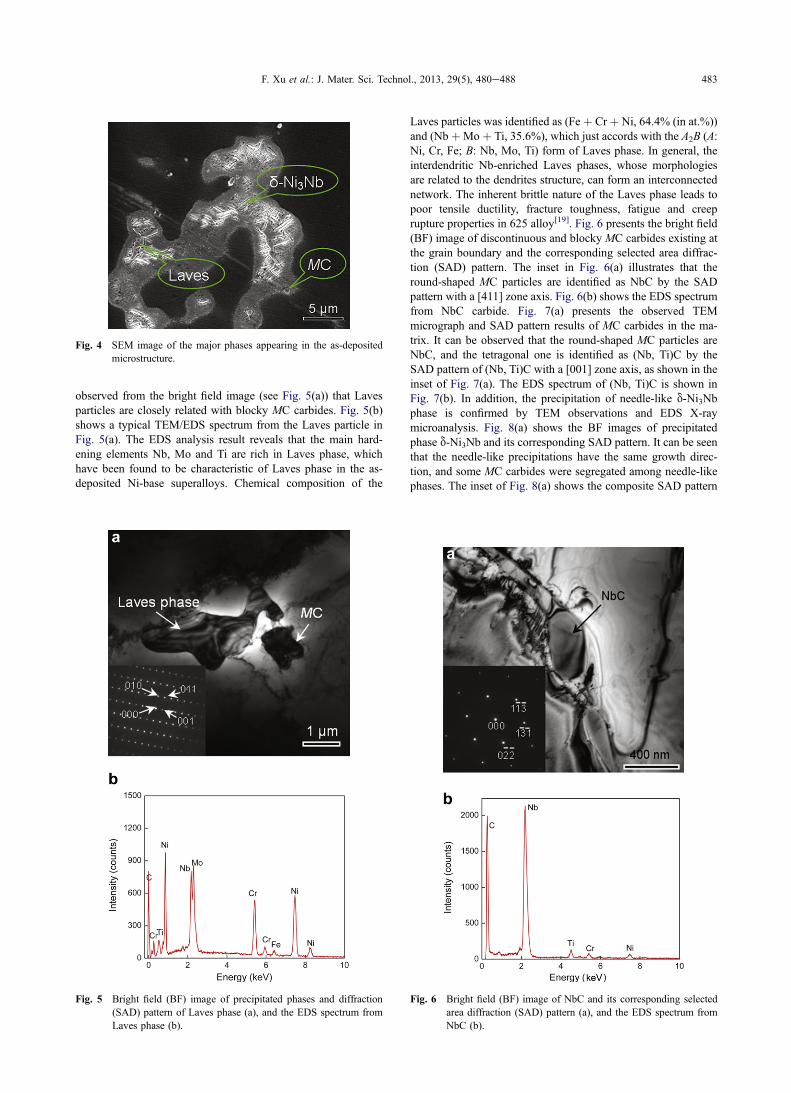
Fig. 4 SEM image of the major phases appearing in the as-depositedmicrostructure.
F. Xu et al.: J. Mater. Sci. Technol., 2013, 29(5), 480e488 483
observed from the bright field image (see Fig. 5(a)) that Lavesparticles are closely related with blocky MC carbides. Fig. 5(b)shows a typical TEM/EDS spectrum from the Laves particle inFig. 5(a). The EDS analysis result reveals that the main hard-ening elements Nb, Mo and Ti are rich in Laves phase, whichhave been found to be characteristic of Laves phase in the as-deposited Ni-base superalloys. Chemical composition of the
Fig. 5 Bright field (BF) image of precipitated phases and diffraction(SAD) pattern of Laves phase (a), and the EDS spectrum fromLaves phase (b).
Laves particles was identified as (Fe þ Cr þ Ni, 64.4% (in at.%))and (NbþMo þ Ti, 35.6%), which just accords with the A2B (A:Ni, Cr, Fe; B: Nb, Mo, Ti) form of Laves phase. In general, theinterdendritic Nb-enriched Laves phases, whose morphologiesare related to the dendrites structure, can form an interconnectednetwork. The inherent brittle nature of the Laves phase leads topoor tensile ductility, fracture toughness, fatigue and creeprupture properties in 625 alloy[19]. Fig. 6 presents the bright field(BF) image of discontinuous and blocky MC carbides existing atthe grain boundary and the corresponding selected area diffrac-tion (SAD) pattern. The inset in Fig. 6(a) illustrates that theround-shaped MC particles are identified as NbC by the SADpattern with a [411] zone axis. Fig. 6(b) shows the EDS spectrumfrom NbC carbide. Fig. 7(a) presents the observed TEMmicrograph and SAD pattern results of MC carbides in the ma-trix. It can be observed that the round-shaped MC particles areNbC, and the tetragonal one is identified as (Nb, Ti)C by theSAD pattern of (Nb, Ti)C with a [001] zone axis, as shown in theinset of Fig. 7(a). The EDS spectrum of (Nb, Ti)C is shown inFig. 7(b). In addition, the precipitation of needle-like d-Ni3Nbphase is confirmed by TEM observations and EDS X-raymicroanalysis. Fig. 8(a) shows the BF images of precipitatedphase d-Ni3Nb and its corresponding SAD pattern. It can be seenthat the needle-like precipitations have the same growth direc-tion, and some MC carbides were segregated among needle-likephases. The inset of Fig. 8(a) shows the composite SAD pattern
Fig. 6 Bright field (BF) image of NbC and its corresponding selectedarea diffraction (SAD) pattern (a), and the EDS spectrum fromNbC (b).

Fig. 7 Bright field (BF) image of (Nb,Ti)C and its correspondingselected area diffraction (SAD) pattern (a), and the EDS spec-trum from (Nb,Ti)C (b).
Fig. 8 Bright field (BF) images of precipitation phase d-Ni3Nb and itscorresponding selected area diffraction (SAD) pattern (a), andthe EDS spectrum from d-Ni3Nb (b).
484 F. Xu et al.: J. Mater. Sci. Technol., 2013, 29(5), 480e488
of d-Ni3Nb with orthorhombic DO2 and g-Ni. The orientationrelationship between d-Ni3Nb and g-Ni is [001] d-Ni3Nb // ½111�g-Ni. The EDS analysis results show that the main alloy contentsof d phase are Ni, Cr and Nb, as shown in Fig. 8(b).The above observation and analysis can confirm that Laves
phase, MC carbides and needle-like d-Ni3Nb phase precipitatedin the as-deposited microstructure. The distribution characteris-tics of these intermetallic phases in the as-deposited 625 samplewere investigated. Fig. 9(a) and (b) present the detailed micro-structure of the bottom part of the sample. It can be seen thatmany fine discrete Laves particles and MC carbides wereprecipitated in interdendritic region. However, the needle-like d-Ni3Nb phase was not observed. Fig. 9(c) and (d) highlight theSEM microstructures in the interface region between two adja-cent layers. It was observed that Laves particles, MC carbidesand a few needle-like d-Ni3Nb were precipitated in the interfaceregion. The needle-like d-Ni3Nb precipitates grow along theedges of Laves particles, and the amount of d-Ni3Nb is small.Fig. 9(e) and (f) exhibit the precipitation and distribution ofprevious phases at the upper part of the sample. As can be seen,the precipitated phases in columnar dendritic regions are inter-connected and net-shaped. The amount of Laves particles be-comes smaller than those at the bottom part. Moreover, a largenumber of d-Ni3Nb precipitates are precipitated in the form ofmore vimineous morphologies with two direction of growth.According to the previous observation, the precipitation
mechanisms of the major phases appearing in as-deposited 625
alloys were analyzed. In the PPAD process, solidification inInconel 625 alloy starts with the primary liquid / g reaction,causing the accumulation of Nb, Mo, C and Ti elements ininterdendritic and grain boundaries liquid. Thus Laves phase,MC carbides (including NbC and TiC) and d-Ni3Nb canbe precipitated in these regions. Then the subsequentliquid / (g þ NbC) eutectic reaction consumes most carbonavailable until another eutectic reaction L / g þ Laves þ doccurs, finishing the solidification process[20]. Laves phase oc-cupies most useful alloying elements, especially niobium. Thecontent of Nb in Laves phase is up to 21 wt%. Laves phaseappearing in as-deposited microstructure consumes most of theNb originally dissolved in the base material, thereby making lessNb available for the precipitation of the principal strengtheningphase g00-Ni3Nb. The metastable phase g00-Ni3Nb was notdetected in this research. However, a large number of needle-liked-Ni3Nb precipitates existing in the as-deposited microstructurewere identified. The result is different from that of other re-searches on laser deposition and welding process for the Inconel625 alloy[21]. The formation of d-Ni3Nb phase is due to solidi-fication conditions and complex thermal cycling of PPAD pro-cess. During the solidification of PPAD, Ni and Nb elements arerich in the residual liquid after the eutectic reactionL / g þ Laves, which is beneficial to the nucleation andgrowth of d-Ni3Nb. Meanwhile, material is built up layer bylayer during PPAD process. When depositing a new layer ofmaterial, the deposits of the previous layer are heat-treated

Fig. 9 SEM microstructures at bottom (a, b), layers interface (c, d) and upper part (e, f) of the as-deposited Inconel 625 sample.
F. Xu et al.: J. Mater. Sci. Technol., 2013, 29(5), 480e488 485
resulting in the dissolution of Laves phases. Then the releasedniobium elements can be used for the formation of d-Ni3Nb. Itcan be confirmed by the small amount of Laves particles in theas-deposited microstructure of upper part, as shown in Fig. 9(e).In addition, the low cooling rate makes for the precipitation of d-Ni3Nb in this research. As can be seen, many fine discrete Lavesparticles precipitated at the bottom part of the as-depositedsample without d-Ni3Nb (see Fig. 9(a)), which is caused byhigh cooling rate. The marked segregation of solute elements isprevented because of the insufficient time for solute redistribu-tion. Hence, finer Laves particles and a lower Nb concentrationin the interdendritic region are obtained. When depositing theupper part layers, the cooling rate becomes low, resulting fromheat accumulation. Therefore more solute elements are rich inthe interdendritic area, resulting in the precipitation of a largenumber of d-Ni3Nb. The presence of needle-like d-phase inexcessive amounts was found to be detrimental for stress rupture
properties of Inconel 718 by GTAW (gas tungsten arc weld-ing)[22]. In addition, when depositing a layer of material, thedendrites of the top portion always grow preferably incliningtoward the scanning direction because of the temperaturegradient direction changing from the deposition direction at thebottom of molten pool to the scanning direction at the top of themolten pool. However, the orientation transition of dendritesgrowth was not observed, resulting from top portion remeltingduring the subsequent layer deposition. Therefore, dendritegrowth directions within two adjacent layers were the same. Forthe solidification process of the layer interface, the temperaturegradient is very high but the cooling rate is very low. As a result,layer interface consisting of fine cellular structure and pre-cipitates can be observed. These layer interface regions areusually associated with sharp changes in grain size and degree ofmicrosegregations. Therefore, they can be the weak sites oftensile stress[23].
Fig. 11 Tensile strength (a), yield strength (b) and percentage elonga-
486 F. Xu et al.: J. Mater. Sci. Technol., 2013, 29(5), 480e488
3.2. Mechanical properties
Microhardness measurements were carried out on the trans-verse and longitudinal cross-sections of the as-deposited Inconel625 sample. Fig. 10 presents the microhardness variation profilesfrom bottom to upper part of the as-deposited sample. The resultsreveal microhardness on the transverse cross-section in the rangeof 260e285 HV0.2 with an obvious fluctuation. The micro-hardness of the bottom sample is higher than that of the uppersample because of the finer columnar dendrites and discreteprecipitates. The longitudinal cross-section exhibits slightlylower microhardness in the range of 260e275 HV0.2 with asmall fluctuation. Microhardness at the interface region betweenthe adjacent deposited layers is slightly higher than that of otherregions due to a highly refined structure.Fig. 11 shows the tensile properties of the specimens depos-
ited by PPAD with different fabrication strategies. Tensile testspecimens were machined from the bottom to the upper part ofthe as-deposited sample. Fig. 11(a) indicates that the tensilestrength (in the range of 690e754 MPa) of the specimens withshort raster fabrication strategy is slightly higher than that withlong raster (in the range of 704e742 MPa). The tensile strengthdecreases gradually from the bottom to the upper part of the as-deposited sample. Fig. 11(b) shows yield strength of Inconel 625alloy fabricated with different raster patterns. The variation of theyield strength is similar to that of the tensile strength. Fig. 11(c)presents the test results on the elongation rate of the Inconel 625alloy fabricated with different raster patterns. The results revealthat the percentage elongations of all specimens keep almostconstant (49%). This illustrates that the as-deposited sampleexhibits improved tensile properties without sacrificing elonga-tion. The average tensile properties of the as-deposited samplewith short raster (long raster) are found to be tensile strength721 MPa (718 MPa), yield strength 438 MPa (423 MPa) andpercentage elongation 48.6% (49.2%). The tensile properties ofthe specimens fabricated by using PPAD are compared with theresults of parts additive manufactured by other technologies, aslisted in Table 2. The tensile properties of the specimens fabri-cated by using PPAD are better than those as reported for the as-cast material. Compared with specimens from additive manu-factured by LRM technology, their tensile and yield strength areinferior, but the percentage elongation is close or superior.During the tensile test process, the tensile loading axis is
perpendicular to the raster direction for the short raster
Fig. 10 Microhardness profiles from bottom to upper on transverse andlongitudinal cross-sections.
tion (c) of Inconel 625 alloy fabricated with different rasterpatterns.
specimens. Thus microstructure of the interface between adja-cent layers and overlapping region between weld beads has asignificant impact on the tensile properties. The above resultsimply that the sample is well fabricated and free of micro-defects. Moreover, the fine dendrites and precipitates in the
Table 2 Comparison of tensile properties of differently processedInconel 625
Conditions Tensile properties
Tensile strength(MPa)
Elongation(%)
Yield strength(MPa)
LRM-reported[23] 744e797 31e48 485Cast[1] 710 48 350PPAD 721 49 438
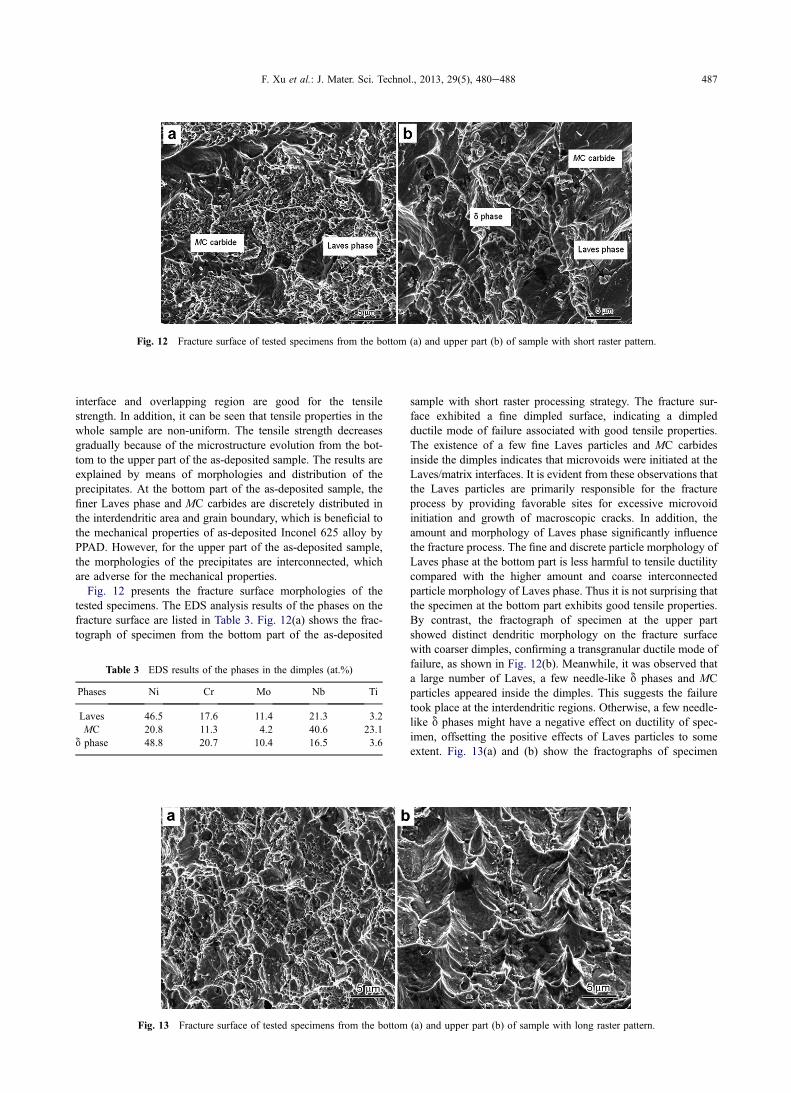
Fig. 12 Fracture surface of tested specimens from the bottom (a) and upper part (b) of sample with short raster pattern.
F. Xu et al.: J. Mater. Sci. Technol., 2013, 29(5), 480e488 487
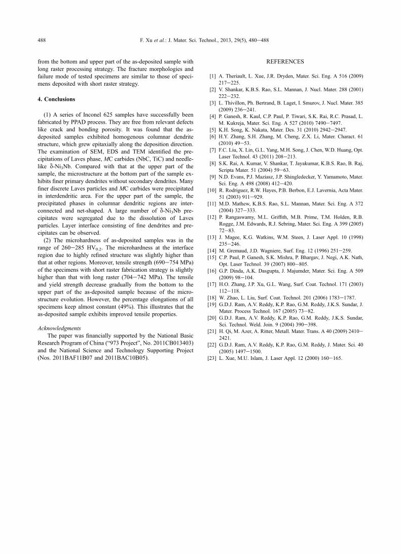
interface and overlapping region are good for the tensilestrength. In addition, it can be seen that tensile properties in thewhole sample are non-uniform. The tensile strength decreasesgradually because of the microstructure evolution from the bot-tom to the upper part of the as-deposited sample. The results areexplained by means of morphologies and distribution of theprecipitates. At the bottom part of the as-deposited sample, thefiner Laves phase and MC carbides are discretely distributed inthe interdendritic area and grain boundary, which is beneficial tothe mechanical properties of as-deposited Inconel 625 alloy byPPAD. However, for the upper part of the as-deposited sample,the morphologies of the precipitates are interconnected, whichare adverse for the mechanical properties.Fig. 12 presents the fracture surface morphologies of the
tested specimens. The EDS analysis results of the phases on thefracture surface are listed in Table 3. Fig. 12(a) shows the frac-tograph of specimen from the bottom part of the as-deposited
Table 3 EDS results of the phases in the dimples (at.%)
Phases Ni Cr Mo Nb Ti
Laves 46.5 17.6 11.4 21.3 3.2MC 20.8 11.3 4.2 40.6 23.1
d phase 48.8 20.7 10.4 16.5 3.6
Fig. 13 Fracture surface of tested specimens from the bottom
sample with short raster processing strategy. The fracture sur-face exhibited a fine dimpled surface, indicating a dimpledductile mode of failure associated with good tensile properties.The existence of a few fine Laves particles and MC carbidesinside the dimples indicates that microvoids were initiated at theLaves/matrix interfaces. It is evident from these observations thatthe Laves particles are primarily responsible for the fractureprocess by providing favorable sites for excessive microvoidinitiation and growth of macroscopic cracks. In addition, theamount and morphology of Laves phase significantly influencethe fracture process. The fine and discrete particle morphology ofLaves phase at the bottom part is less harmful to tensile ductilitycompared with the higher amount and coarse interconnectedparticle morphology of Laves phase. Thus it is not surprising thatthe specimen at the bottom part exhibits good tensile properties.By contrast, the fractograph of specimen at the upper partshowed distinct dendritic morphology on the fracture surfacewith coarser dimples, confirming a transgranular ductile mode offailure, as shown in Fig. 12(b). Meanwhile, it was observed thata large number of Laves, a few needle-like d phases and MCparticles appeared inside the dimples. This suggests the failuretook place at the interdendritic regions. Otherwise, a few needle-like d phases might have a negative effect on ductility of spec-imen, offsetting the positive effects of Laves particles to someextent. Fig. 13(a) and (b) show the fractographs of specimen
(a) and upper part (b) of sample with long raster pattern.
488 F. Xu et al.: J. Mater. Sci. Technol., 2013, 29(5), 480e488
from the bottom and upper part of the as-deposited sample withlong raster processing strategy. The fracture morphologies andfailure mode of tested specimens are similar to those of speci-mens deposited with short raster strategy.
4. Conclusions
(1) A series of Inconel 625 samples have successfully beenfabricated by PPAD process. They are free from relevant defectslike crack and bonding porosity. It was found that the as-deposited samples exhibited homogenous columnar dendritestructure, which grew epitaxially along the deposition direction.The examination of SEM, EDS and TEM identified the pre-cipitations of Laves phase, MC carbides (NbC, TiC) and needle-like d-Ni3Nb. Compared with that at the upper part of thesample, the microstructure at the bottom part of the sample ex-hibits finer primary dendrites without secondary dendrites. Manyfiner discrete Laves particles and MC carbides were precipitatedin interdendritic area. For the upper part of the sample, theprecipitated phases in columnar dendritic regions are inter-connected and net-shaped. A large number of d-Ni3Nb pre-cipitates were segregated due to the dissolution of Lavesparticles. Layer interface consisting of fine dendrites and pre-cipitates can be observed.(2) The microhardness of as-deposited samples was in the
range of 260e285 HV0.2. The microhardness at the interfaceregion due to highly refined structure was slightly higher thanthat at other regions. Moreover, tensile strength (690e754 MPa)of the specimens with short raster fabrication strategy is slightlyhigher than that with long raster (704e742 MPa). The tensileand yield strength decrease gradually from the bottom to theupper part of the as-deposited sample because of the micro-structure evolution. However, the percentage elongations of allspecimens keep almost constant (49%). This illustrates that theas-deposited sample exhibits improved tensile properties.
AcknowledgmentsThe paper was financially supported by the National Basic
Research Program of China (“973 Project”, No. 2011CB013403)and the National Science and Technology Supporting Project(Nos. 2011BAF11B07 and 2011BAC10B05).
REFERENCES
[1] A. Theriault, L. Xue, J.R. Dryden, Mater. Sci. Eng. A 516 (2009)217e225.
[2] V. Shankar, K.B.S. Rao, S.L. Mannan, J. Nucl. Mater. 288 (2001)222e232.
[3] L. Thivillon, Ph. Bertrand, B. Laget, I. Smurov, J. Nucl. Mater. 385(2009) 236e241.
[4] P. Ganesh, R. Kaul, C.P. Paul, P. Tiwari, S.K. Rai, R.C. Prasad, L.M. Kukreja, Mater. Sci. Eng. A 527 (2010) 7490e7497.
[5] K.H. Song, K. Nakata, Mater. Des. 31 (2010) 2942e2947.[6] H.Y. Zhang, S.H. Zhang, M. Cheng, Z.X. Li, Mater. Charact. 61
(2010) 49e53.[7] F.C. Liu, X. Lin, G.L. Yang, M.H. Song, J. Chen, W.D. Huang, Opt.
Laser Technol. 43 (2011) 208e213.[8] S.K. Rai, A. Kumar, V. Shankar, T. Jayakumar, K.B.S. Rao, B. Raj,
Scripta Mater. 51 (2004) 59e63.[9] N.D. Evans, P.J. Maziasz, J.P. Shingledecker, Y. Yamamoto, Mater.
Sci. Eng. A 498 (2008) 412e420.[10] R. Rodriguez, R.W. Hayes, P.B. Berbon, E.J. Lavernia, Acta Mater.
51 (2003) 911e929.[11] M.D. Mathew, K.B.S. Rao, S.L. Mannan, Mater. Sci. Eng. A 372
(2004) 327e333.[12] P. Rangaswamy, M.L. Griffith, M.B. Prime, T.M. Holden, R.B.
Rogge, J.M. Edwards, R.J. Sebring, Mater. Sci. Eng. A 399 (2005)72e83.
[13] J. Magee, K.G. Watkins, W.M. Steen, J. Laser Appl. 10 (1998)235e246.
[14] M. Gremaud, J.D. Wagniere, Surf. Eng. 12 (1996) 251e259.[15] C.P. Paul, P. Ganesh, S.K. Mishra, P. Bhargav, J. Negi, A.K. Nath,
Opt. Laser Technol. 39 (2007) 800e805.[16] G.P. Dinda, A.K. Dasgupta, J. Majumder, Mater. Sci. Eng. A 509
(2009) 98e104.[17] H.O. Zhang, J.P. Xu, G.L. Wang, Surf. Coat. Technol. 171 (2003)
112e118.[18] W. Zhao, L. Liu, Surf. Coat. Technol. 201 (2006) 1783e1787.[19] G.D.J. Ram, A.V. Reddy, K.P. Rao, G.M. Reddy, J.K.S. Sundar, J.
Mater. Process Technol. 167 (2005) 73e82.[20] G.D.J. Ram, A.V. Reddy, K.P. Rao, G.M. Reddy, J.K.S. Sundar,
Sci. Technol. Weld. Join. 9 (2004) 390e398.[21] H. Qi, M. Azer, A. Ritter, Metall. Mater. Trans. A 40 (2009) 2410e
2421.[22] G.D.J. Ram, A.V. Reddy, K.P. Rao, G.M. Reddy, J. Mater. Sci. 40
(2005) 1497e1500.[23] L. Xue, M.U. Islam, J. Laser Appl. 12 (2000) 160e165.