microsoft hyper-v and system center virtual machine manager · deploying f5 with microsoft hyper-v...
TRANSCRIPT

Deploying F5 with Microsoft Hyper-V and System Center Virtual Machine Manager 2008
DEPLOYMENT GUIDE Version 1.1

Table of Contents
Table of Contents
Deploying F5 with Microsoft Hyper-V and System Center Virtual Machine Manager 2008Prerequisites and configuration notes ..............................................................................1-2Revision history ......................................................................................................................1-2
Configuring the BIG-IP LTM system for Hyper-V and SCVMMLoad balancing applications running on virtual machines .............................................1-3Considerations for the health monitor ............................................................................1-5Load balancing behavior with Quick Migration ..............................................................1-6Using LTM to improve hardware capacity in a virtual environment .........................1-7Creating BIG-IP LTM profiles to optimize application transactions ....................... 1-10
Configuring the WebAccelerator module with applications running on Hyper-V Prerequisites and configuration notes ..............................................................................2-1Configuration example .........................................................................................................2-1Configuring the WebAccelerator module .......................................................................2-2Connecting to the BIG-IP LTM device ..............................................................................2-2Creating an HTTP Class profile .........................................................................................2-2Modifying the Virtual Server to use the Class profile ...................................................2-3Creating an Application ........................................................................................................2-4
Using BIG-IP GTM to provide global site redirection to a secondary data centerConfiguring a self IP address on the BIG-IP LTM ...........................................................3-2Creating a Listener on the GTM ........................................................................................3-2Creating data centers on the GTM system .....................................................................3-3Creating the monitor ............................................................................................................3-4Creating Servers for the data center ................................................................................3-5Creating a GTM pool ............................................................................................................3-6Creating a wide IP on the GTM .........................................................................................3-8Configuring the Wide IP as an MX record using ZoneRunner ...................................3-9
Configuring BIG-IP WOM with Microsoft Hyper-V ServersCommon Scenarios ...............................................................................................................4-1
Configuring the WAN optimization module ............................................................................4-2Creating the iSession profile ...............................................................................................4-4Creating the WAN Optimization policy ..........................................................................4-4
F5 Deployment Guide i

1
Deploying F5 with Microsoft Hyper-V and System Center Virtual Machine Manager 2008• Configuring the BIG-IP LTM system for Hyper-V and SCVMM
• Load balancing applications running on virtual machines
• Load balancing behavior with Quick Migration
• Using LTM to improve hardware capacity in a virtual environment

Deploying F5 with Microsoft Hyper-V and System Center Virtual Machine Manager 2008
Welcome to the F5 Deployment Guide for Microsoft Hyper-V. This document provides guidance and configuration procedures for deploying the BIG-IP Local Traffic Manager (LTM), BIG-IP Global Traffic Manager (GTM), WebAccelerator, and BIG-IP WAN Optimization Module (WOM) with platforms and applications running on Microsoft Hyper-V. Although much of the guidance given is applicable to standalone Hyper-V servers, we focus on clustered Hyper-V servers managed by Microsoft System Center Virtual Machine Manager 2008 (SCVMM).
Microsoft Hyper-V, which is available as a part of Windows Server 2008, is a high-performance virtual machine hypervisor that brings additional deployment flexibility to the data center and permits a more dense and efficient use of hardware resources through server consolidation. Hyper-V servers can be managed through SCVMM, and Hyper-V virtual machines can be deployed in a variety of highly-available scenarios through a combination of network-based load balancing and Windows Failover Clustering. By using F5 products in conjunction with Hyper-V, you can increase uptime, accelerate end-user experience, and reduce load on your virtual machines.
For more information on Hyper-V see: www.microsoft.com/windowsserver2008/en/us/virtualization-consolidation.aspx
Additional tools and technical resources, including information on System Center Virtual Machine Manager, are available here: http://technet.microsoft.com/en-us/virtualization/default.aspx
For additional resources on F5 and Hyper-V, see the Microsoft page on DevCentral.
Important
This guide is different than F5's typical Deployment Guides. Most F5 configuration is highly dependent on which applications are running within the virtual machines. Therefore, most of this document provides general guidance and additional best practices for deploying F5 devices with applications virtualized on Hyper-V. Refer to the Deployment Guide appropriate to your application for specific configuration procedures.
This Deployment Guide is broken up into the following chapters:
• Configuring the BIG-IP LTM system for Hyper-V and SCVMM, on page 1-3
• Configuring the F5 WebAccelerator module with applications running on Hyper-V, on page 2-1
• Using BIG-IP GTM to provide global site redirection to a secondary data center, on page 3-1
• Configuring BIG-IP WOM with Microsoft Hyper-V Servers, on page 4-1
1 - 1
Deploying F5 with Microsoft Hyper-V and System Center Virtual Machine Manager 2008
Prerequisites and configuration notes The following are prerequisites for this solution:
◆ The scenarios outlined in this Deployment Guide were tested using pre-release versions of Microsoft System Center Virtual Machine Manager 2008. It is possible that specific behaviors may change in the final version of the product.
◆ We recommend running BIG-IP LTM version 9.4 or later.
◆ Within the context of this deployment guide, virtual server is used to refer to an IP address and port on a BIG-IP LTM which accepts network traffic. The term virtual machine is used to refer to a virtualized guest operating system.
Revision historyThe following is a revision history for this guide:
Document Version Description
1.0 New guide
1.1 Replaced previous WAN optimization guidance with the BIG-IP WAN Optimization module (WOM) configuration procedures.
F5 Deployment Guide 1 - 2

Configuring the BIG-IP LTM system for Hyper-V and SCVMM
This section provides general guidance for deploying the BIG-IP LTM system with Hyper-V. This section contains the following topics:
• Load balancing applications running on virtual machines
• Considerations for the health monitor, on page 1-5
• Load balancing behavior with Quick Migration, on page 1-6
• Using LTM to improve hardware capacity in a virtual environment, on page 1-7
Load balancing applications running on virtual machinesIn most ways, an application within a Hyper-V virtual machine behaves much like an application running outside of a virtualized environment. A BIG-IP LTM directs traffic to the network address and port of an application, defined in an LTM pool; those applications can reside on virtual machines that are themselves distributed among any number of Hyper-V servers.
Figure 1.1 Using the BIG-IP LTM to direct traffic to Hyper-V deployments
Firewalls
Internet
BIG-IP Local Traffic Manager
Hyper-V Server 1
Clients
VM1 VM2 VM3 VM7 VM8 VM9VM4 VM5 VM6
Hyper-V Server 2 Hyper-V Server 3
1 - 3

Deploying F5 with Microsoft Hyper-V and System Center Virtual Machine Manager 2008
Considerations for load balancing method
When configuring a BIG-IP LTM system, the IP addresses and Service Ports of the target application are added to a load balancing pool.
For each BIG-IP LTM pool that contains an Hyper-V hosted application, we recommend choosing one of the following load balancing methods:
◆ Observed (member) The Observed load balancing method allows the BIG-IP LTM to determine the optimal Hyper-V-hosted application to which new traffic should be directed, based on the lowest number of outstanding Layer-4 connections. Since virtualized applications may be contending for resources with other virtual machines on the same hardware, this ensures that new traffic is sent to the pool member most able to handle the traffic. For instance, if a Hyper-V server is engaged in heavy disk activity due to events occurring within other virtual machines, and the target virtual machine is therefore unable to process requests in as timely a manner as during normal situations, LTM will dynamically adjust traffic levels to target those virtual machines on other servers that are better able to process the traffic. The Observed method is particularly useful when Hyper-V hosts may be of dissimilar hardware profiles, or when applications are not evenly distributed throughout an environment.
◆ Predictive (member) The Predictive load balancing method is similar to Observed, except that it also takes into account trending of each pool member. In a highly-dynamic Hyper-V environment, or one that is subject to extreme traffic fluctuations, the Predictive algorithm may more accurately distribute connections to the virtual machines that are mostly likely to offer a quick response.
Tip
For details on the behavior of Observed and Predictive load balancing methods, see SOL6406 on Ask F5.
To modify the load balancing method of a BIG-IP LTM pool
1. On the Main tab, expand Local Traffic, and then click Pools.The Pool screen opens.
2. From the Pool list, click the name of the applicable pool.The Pool Properties screen opens.
3. On the menu bar, click Members.
4. From the Load Balancing Method list, select Observed (member) or Predictive (member) based on the preceding descriptions.
F5 Deployment Guide 1 - 4

5. Click the Update button.
Figure 1.2 Changing the load balancing method of the pool
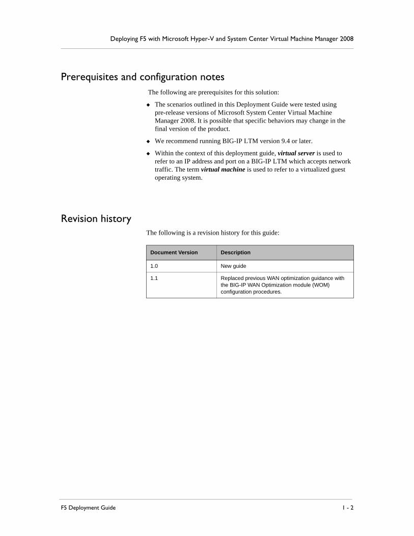
Considerations for the health monitorHealth monitors for applications running in virtual machines should be based on application behavior, not simple methods such as ICMP or TCP. For example, for a web-based application, we recommend an advanced health monitor based on the HTTP parent that checks for a specific response string from the application. This ensures that newly-provisioned, newly-unsuspended, or newly-migrated guests, especially those with external dependencies that may themselves be in virtual machines, are truly ready to process application traffic correctly.
To create an advanced health monitor
1. On the Main tab, expand Local Traffic, and then click Monitors.
2. Click the Create button. The New Monitor screen opens.
3. In the Name box, type a name for the Monitor.In our example, we type advhttp-monitor.
4. From the Type list, select http.
5. In the Configuration section, in the Interval and Timeout boxes, type an Interval and Timeout. We recommend at least a 1:3 +1 ratio between the interval and the timeout (for example, the default setting has an interval of 5 and an timeout of 16). In our example, we use a Interval of 30 and a Timeout of 91.In the Send String and Receive Rule sections, you can add a Send String and Receive Rule specific to the application being checked.
6. In the Send String box, type a string that you expect the target application to return. In our example, we use a Send String of GET/ iisstart.htm.
If the page you are requesting in the Send String requires authentication, type a user name and password in the appropriate boxes.
1 - 5
Deploying F5 with Microsoft Hyper-V and System Center Virtual Machine Manager 2008
7. In the Receive Rule box, type what you expect to receive from the Send String. In our example, we expect the Under Construction page to be returned, so we type [Uu]nder [Cc]onstruction (see Figure 1.3).
8. Click the Finished button.The new monitor is added to the Monitor list.
Figure 1.3 Creating an advanced HTTP monitor
Load balancing behavior with Quick Migration When deployed as part of a Windows Failover Cluster and managed by SCVMM, Hyper-V virtual machines can be moved from one physical server to another with minimal downtime through a process known as Quick Migration. During a Quick Migration, the virtual machine is suspended, the contents of the virtual machine's memory are copied to the new host, and the machine is brought out of suspension. The time the machine is unavailable generally ranges from 10-30 seconds; that value is highly dependent on memory used by each virtual machine. We recommend testing a Quick Migration under conditions that simulate normal expected load in order to obtain a baseline value, which you will use in configuring monitors.
To determine appropriate monitor and load balancing settings that accommodate a Quick Migration, it is important to understand the application behavior.
F5 Deployment Guide 1 - 6

◆ Short-lived, stateless connections should have health monitors with a relatively short timeout so that connections are quickly sent on to other virtual machines. Examples of such connections are typical HTTP requests, SMTP, or DNS requests. In these cases, we recommend using default timeout values as shipped in LTM, or following application-specific F5 Deployment Guides when those offer further guidance.
◆ Many longer-lived, stateful connections should have a longer timeout associate with the monitor. For example, a Remote Desktop Connection to a Microsoft Terminal Services server will maintain desktop state across a dropped connection. In such a case, it is not desirable to send a user to another pool member unless the original member is truly down, rather than simply suspended for a brief time. For these types of applications, we suggest using a health monitor timeout value that is longer than the maximum time that it takes for your application to undergo a Quick Migration under load. If your application takes 30 seconds to be migrated, a 35 second timeout might be appropriate.
◆ Some long-lived connections, based on the application, will not be maintained across a virtual machine Quick Migration regardless of settings. For instance, an in-progress FTP download will terminate during a Quick Migration. In those scenarios, we suggest keeping short health monitor time-outs so that users are quickly able to establish new connections with available virtual machines.
(See To create an advanced health monitor, on page 1-5 for instructions on how to configure the health monitors).
After a Quick Migration, BIG-IP LTM continues to direct traffic to the virtual machine on the new host; to LTM, since the IP address and port have not changed, this is still the same pool member. By using Predictive or Observed load balancing methods, as explained above, traffic is automatically sent to the virtual machine at a level appropriate to the capacities of the virtual machine, which is now running on a host that may be more or less constrained than the previous one.
Using LTM to improve hardware capacity in a virtual environmentHyper-V virtual machines share the CPU, disk, and RAM resources of their hosts. By decreasing the per-transaction resources required by each guest, you can dramatically increase the number of virtual machines that can run effectively on any host, while also increasing the effective work that each virtual machine can accomplish.
For instance, each Hyper-V virtual machine uses one or more Microsoft synthetic network adapters, rather than having direct access to a hardware network adapter. These synthetic adapters do not provide a TOE (TCP/IP Offload Engine), SSL offloading, or any other hardware-based acceleration
1 - 7
Deploying F5 with Microsoft Hyper-V and System Center Virtual Machine Manager 2008
technologies. Using a BIG-IP LTM, with dedicated high-speed hardware and the BIG-IP TCP Express feature set, you move a large amount of required processing off of the virtual machines.
The F5 WebAccelerator (available as a module on the BIG-IP system) can also significantly improve hardware capacity in a virtual environment. See Configuring the F5 WebAccelerator module with applications running on Hyper-V, on page 2-1.
Offloading SSL transactions
One of the strengths of the BIG-IP LTM is the ability to terminate HTTPS or other SSL connections, and send traffic to the guests unencrypted. This reduces CPU and memory load on Hyper-V virtual machines by using the dedicated decryption hardware on the LTM. By terminating SSL/TLS connections at the BIG-IP LTM, you also simplify certificate management, and allow new virtual machines to come online quickly and inexpensively.
To configure the BIG-IP LTM system to offload SSL you need to install a SSL certificate on the BIG-IP LTM and add the certificate and key to a Client SSL profile which is added to the appropriate virtual server. The following procedures describe how to import an SSL certificate into the BIG-IP LTM, how to add the certificate to a profile, and how to modify the virtual server to include the profile.
For information on generating certificates, or using the BIG-IP LTM to generate a request for a new certificate and key from a certificate authority, see the Managing SSL Traffic chapter in the Configuration Guide for Local Traffic Management.
Importing keys and certificates
Once you have obtained a certificate from a certificate authority, you can import this certificate into the BIG-IP LTM system using the Configuration utility.
To import a key or certificate
1. On the Main tab, expand Local Traffic.
2. Click SSL Certificates. The list of existing certificates displays.
3. In the upper right corner of the screen, click Import.
4. From the Import Type list, select the type of import (Certificate or Key).
5. In the Certificate (or Key) Name box, type a unique name for the certificate or key.
6. In the Certificate (or Key) Source box, choose to either upload the file or paste the text.
7. Click Import.
F5 Deployment Guide 1 - 8
If you imported the certificate, repeat this procedure for the key.
Creating a Client SSL profile
The next step is to create a Client SSL profile. This profile contains the SSL certificate and Key information for decrypting the SSL traffic on behalf of the servers.
To create a new Client SSL profile
1. On the Main tab, expand Local Traffic, and then click Profiles.The HTTP Profiles screen opens.
2. On the Menu bar, from the SSL menu, select Client.The Client SSL Profiles screen opens.
3. In the upper right portion of the screen, click the Create button.The New Client SSL Profile screen opens.
4. In the Name box, type a name for this profile. In our example, we type clientssl-profile.
5. In the Configuration section, check the Certificate and Key Custom boxes.
6. From the Certificate list, select the name of the Certificate you imported in the Importing keys and certificates section.
7. From the Key list, select the key you imported in the Importing keys and certificates section.
8. Click the Finished button.
Modifying the virtual server to include the Client SSL profile
The final task to enable the BIG-IP LTM to offload SSL is to modify the appropriate virtual server to include the Client SSL profile you just created.
To modify an existing virtual server to use the Client SSL profile
1. On the Main tab, expand Local Traffic, and then click Virtual Servers. The Virtual Servers screen opens.
2. From the Virtual Server list, click the virtual server that will be offloading SSL traffic.
3. In the Configuration section, from the SSL Profile (Client) list, select the name of the profile you created in Creating a Client SSL profile. In our example, we select clientssl-profile.
1 - 9

Deploying F5 with Microsoft Hyper-V and System Center Virtual Machine Manager 2008
4. Click the Update button.
Figure 1.4 Adding the Client SSL profile to the virtual server
Creating BIG-IP LTM profiles to optimize application transactionsThe BIG-IP LTM system uses profiles to enhance your control over managing network traffic, and makes traffic-management tasks easier and more efficient. For applications running in Hyper-V virtual machines, we recommend using custom HTTP and TCP profiles to optimize the BIG-IP LTM to virtual machine connections. This allows each application to perform as efficiently as possible. The optimized HTTP profile makes use of F5's RAM cache and compression engine which speed application transactions.
Although it is possible to use the default profiles, we strongly recommend you create new profiles based on the default parent profiles, even if you do not change any of the settings initially. Creating new profiles allows you to easily modify the profile settings specific to the application, and ensures you do not accidentally overwrite the default profile.
Creating an HTTP profile
The HTTP profile contains numerous configuration options for how the BIG-IP LTM system handles HTTP traffic. In the following example, we leave all settings at their default levels. You can modify any of the profile settings to tune the profile to your application. Although you can use the default profiles, we strongly recommend creating new profiles based off of the parent profile to make
To create a new HTTP profile
1. On the Main tab, expand Local Traffic, and then click Profiles.The HTTP Profiles screen opens.
F5 Deployment Guide 1 - 10
2. In the upper right portion of the screen, click the Create button. The New HTTP Profile screen opens.
3. In the Name box, type a name for this profile. In our example, we type http-optimized.
4. From the Parent Profile list, select http-wan-optimized-compression-caching.
5. Check the Custom box for Content Compression, and leave Content List selected.
6. Modify any of the other settings as applicable for your network. In our example, we leave the settings at their default levels.
7. Click the Finished button.
Creating the WAN optimized TCP profile
The next profile we create is a WAN optimized profile.
To create a new TCP profile
1. On the Main tab, expand Local Traffic, and then click Profiles.The HTTP Profiles screen opens.
2. On the Menu bar, from the Protocol menu, click tcp.
3. In the upper right portion of the screen, click the Create button. The New TCP Profile screen opens.
4. In the Name box, type a name for this profile. In our example, we type optimized-tcp-wan.
5. From the Parent Profile list, select tcp-wan-optimized.
6. Modify any of the settings as applicable for your network. In our example, we leave the settings at their default levels.
7. Click the Finished button.
Creating the LAN optimized TCP profile
The next profile we create is a LAN optimized profile.
To create a new TCP profile
1. On the Main tab, expand Local Traffic, and then click Profiles.The HTTP Profiles screen opens.
2. On the Menu bar, from the Protocol menu, click tcp.
3. In the upper right portion of the screen, click the Create button. The New TCP Profile screen opens.
4. In the Name box, type a name for this profile. In our example, we type optimized-tcp-lan.
5. From the Parent Profile list, select tcp-lan-optimized.
1 - 11

Deploying F5 with Microsoft Hyper-V and System Center Virtual Machine Manager 2008
6. Modify any of the settings as applicable for your network. In our example, we leave the settings at their default levels.
7. Click the Finished button.
Modifying the virtual server to use the new profiles
The next task is to modify the virtual server to use the new profiles you just created.
1. On the Main tab, expand Local Traffic, and then click Virtual Servers. The Virtual Servers screen opens.
2. From the Virtual Server list, click the virtual server that will use the new profiles.
3. From the Configuration list, select Advanced.The Advanced configuration options appear.
4. From the Protocol Profile (Client) list, select the name of the profile you created in the Creating the WAN optimized TCP profile section. In our example, we select optimized-tcp-wan.
5. From the Protocol Profile (Server) list, select the name of the profile you created in the Creating the LAN optimized TCP profile section. In our example, we select optimized-tcp-lan.
6. From the HTTP Profile list, select the name of the profile you created in the Creating an HTTP profile section. In our example, we select http-optimized.
7. Click the Update button.
This concludes the BIG-IP LTM system guidance for Hyper-V.
F5 Deployment Guide 1 - 12

1 - 13
2
Deploying the BIG-IP WebAccelerator with Microsoft Hyper-V

Configuring the F5 WebAccelerator module with applications running on Hyper-V
In this chapter, we configure the WebAccelerator module for the Microsoft Hyper-V hosted applications to improve hardware capacity in a virtual environment. The F5 WebAccelerator is an advanced web application delivery solution that provides a series of intelligent technologies designed to overcome problems with browsers, web application platforms and WAN latency issues which impact user performance.
For more information on the F5 WebAccelerator, see www.f5.com/products/big-ip/product-modules/webaccelerator.html.
Prerequisites and configuration notesThe following are prerequisites for this section:
◆ We assume that you have already configured the BIG-IP LTM system for directing traffic to the Hyper-V deployment as described in Chapter 1 of this Deployment Guide.
◆ You must have purchased and licensed the WebAccelerator module on the BIG-IP LTM system, version 9.4 or later.
◆ If you are using the BIG-IP LTM version 9.4.2 or later, you must have created an HTTP profile on the BIG-IP LTM system that has RAM Cache enabled. In our example we use a parent profile that includes RAM Cache. If you did not create an HTTP profile with RAM Cache enabled, you must create a new HTTP profile, based on a parent profile that uses RAM Cache (we recommend HTTP Acceleration) and associate it with the virtual server. This is only required for BIG-IP LTM version 9.4.2 and later.
Configuration example Using the configuration in this section, the BIG-IP LTM system with WebAccelerator module is optimally configured to improve hardware capacity for the Hyper-V servers. The BIG-IP LTM with WebAccelerator module both offloads the servers from serving repetitive and duplicate content.
In this configuration, a remote client with WAN latency accesses an Hyper-V device via the WebAccelerator. The user’s request is accelerated on repeat visits by the WebAccelerator instructing the browser to use the dynamic or static object that is stored in its local cache. Additionally, dynamic and static objects are cached at the WebAccelerator so that they can be served quickly without requiring the server to re-serve the same objects.
2 - 1

Deploying the BIG-IP WebAccelerator with Microsoft Hyper-V
Configuring the WebAccelerator moduleConfiguring the WebAccelerator module requires creating an HTTP class profile and creating an Application. The WebAccelerator device has a large number of other features and options for fine tuning performance gains, see the WebAccelerator Administrator Guide for more information.
Connecting to the BIG-IP LTM deviceUse the following procedure to access the BIG-IP LTM system’s web-based Configuration utility using a web browser.
To connect to the BIG-IP LTM system using the Configuration utility
1. In a browser, type the following URL:https://<administrative IP address of the BIG-IP device>A Security Alert dialog box appears, click Yes.The authorization dialog box appears.
2. Type your user name and password, and click OK. The Welcome screen opens.
Creating an HTTP Class profileThe first procedure is to create an HTTP class profile. When incoming HTTP traffic matches the criteria you specify in the WebAccelerator class, the system diverts the traffic through this class. In the following example, we create a new HTTP class profile, based on the default profile.
To create a new HTTP class profile
1. On the Main tab, expand WebAccelerator, and then click Classes.The HTTP Class Profiles screen opens.
2. In the upper right portion of the screen, click the Create button. The New HTTP Class Profile screen opens.
3. In the Name box, type a name for this Class. In our example, we type example-class.
4. From the Parent Profile list, make sure httpclass is selected.
5. In the Configuration section, from the WebAccelerator row, make sure Enabled is selected.
6. In the Hosts row, from the list select Match Only. The Host List options appear.
a) In the Host box, type the host name that your end users use to access the application running within the Hyper-V virtual machine. In our example, we type http://example-application.f5.com/.
F5 Deployment Guide 2 - 2
b) Leave the Entry Type at Pattern String.
c) Click the Add button.
d) Repeat these sub-steps for any other host names users might use to access the Hyper-V deployment.
7. The rest of the settings are optional, configure them as applicable for your deployment.
8. Click the Finished button. The new HTTP class is added to the list.
Modifying the Virtual Server to use the Class profileThe next step is to modify the virtual server on the BIG-IP LTM system to use the HTTP Class profile you just created.
To modify the Virtual Server to use the Class profile
1. On the Main tab, expand Local Traffic, and then click Virtual Servers. The Virtual Servers screen opens.
2. From the Virtual Server list, click the name of the virtual server you created for the application running within the Hyper-V virtual machine. In our example, we click example-http-vs.The General Properties screen for the Virtual Server opens.
3. On the Menu bar, click Resources.
4. In the HTTP Class Profiles section, click the Manage button.
5. From the Available list, select the name of the HTTP Class Profile you created in the preceding procedure, and click the Add (<<) button to move it to the Enabled box. In our example, we select example-class.
6. Click the Update button. The HTTP Class Profile is now associated with the Virtual Server.
Important
If you are using the BIG-IP LTM version 9.4.2 or later, you must have created an HTTP profile on the BIG-IP LTM system that has RAM Cache enabled. In our example, we use a parent profile that includes RAM Cache. If you did not create an HTTP profile with RAM Cache enabled, you must create a new HTTP profile, based on a parent profile that uses RAM Cache (such as HTTP Acceleration), and modify the virtual server to use this new profile. This is only required for BIG-IP LTM version 9.4.2 and later.
To create the HTTP profile, use Creating an HTTP profile, on page 1-10, selecting the HTTP Acceleration parent profile. You must leave RAM Cache enabled; all other settings are optional. To modify the virtual server, follow Steps 1 and 2 from the preceding procedure to access the virtual server, and then from the HTTP Profile list, select the name of the new profile you just created and click Update.
2 - 3
Deploying the BIG-IP WebAccelerator with Microsoft Hyper-V
Creating an ApplicationThe next procedure is to create a WebAccelerator Application. The Application provides key information to the WebAccelerator so that it can handle requests to your application appropriately.
To create a new Application
1. On the Main tab, expand WebAccelerator, and then click Applications.The Application screen of the WebAccelerator UI opens in a new window.
2. Click the New Application button.
3. In the Application Name box, type a name for your application. In our example, we type Example Application.
4. In the Description box, you can optionally type a description for this application.
5. From the Local Policies list, select the Policy that best matches the application you are running in the virtual machine. If there is not a predefined policy for your application, you can create a new WebAccelerator policy for your application.
6. In the Requested Host box, type the host name that your end users use to access the application. This should be the same host name you used in Step 6a in the preceding procedure. In our example, we type http://example-application.f5.com/.If you have additional host names, click the Add Host button and enter the host name(s).
7. Click the Save button.
The rest of the configuration options on the WebAccelerator are optional, configure these as applicable for your network. With this base configuration, your end users will notice a marked improvement in performance after their first visit.
F5 Deployment Guide 2 - 4

2 - 5

3
Deploying the BIG-IP GTM for Microsoft Hyper-V multi-data center deployments

Using BIG-IP GTM to provide global site redirection to a secondary data center
In this chapter, we configure the BIG-IP Global Traffic Manager for multi-data center deployments of Hyper-V.
The BIG-IP Global Traffic Manager module (GTM) can perform all required functions to make this possible. If for instance Site 1 becomes unavailable because its Internet connection is severed, BIG-IP-GTM modifies DNS to direct clients to Site 2 when appropriate - when replication of Hyper-V virtual machines is complete, those virtual machines are running, and the application is accepting traffic.
The BIG-IP GTM is available as a module on the BIG-IP system.
For more information on the BIG-IP GTM, see www.f5.com/products/big-ip/product-modules/global-traffic-manager.html
Figure 3.1 Logical configuration example using BIG-IP Local and Global Traffic Managers
Internet
Clients
BIG-IP LTM and GTM
Hyper-V Server 1
VM1 VM2 VM3 VM4 VM5 VM6
Hyper-V Server 2
Site A: Seattle
BIG-IP LTM and GTM
Hyper-V Server 1
VM1 VM2 VM3 VM4 VM5 VM6
Hyper-V Server 2
Site B: New York
3 - 1

Deploying the BIG-IP GTM for Microsoft Hyper-V multi-data center deployments
Configuring a self IP address on the BIG-IP LTMThe first task in this configuration is to create a unique self IP address on the BIG-IP LTM system for use by the GTM. You need a unique self IP address for each redundant pair of BIG-IP LTM devices in this configuration, so if you have multiple pairs of BIG-IP LTMs you need a unique self IP for each one.
The IP address you choose, and the VLAN to which you assign it, must be accessible by any clients that will be performing DNS queries against the GTM. It may be a private IP address if a Network Address Translation (NAT) device, such as a BIG-IP LTM, a firewall, or a router, is providing a public address and forwarding DNS traffic to the listener.
To create a self IP address
1. On the Main tab, expand Network, and then click Self IPs.The Self IP screen opens.
2. Click the Create button.The new Self IP screen opens.
3. In the IP Address box, type an IP address in the appropriate VLAN (the VLAN you choose in step 5).In our example, we type 10.133.20.70.
4. In the Netmask box, type the corresponding subnet mask.In our example, we type 255.255.255.0.
5. From the VLAN list, select the appropriate VLAN.
6. Click the Finished button.The new self IP address appears in the list.
Creating a Listener on the GTM The next task is to create a listener on the BIG-IP GTM system. A listener instructs the Global Traffic Manager to listen for network traffic destined for a specific IP address. In our case, this specific IP address is the self IP address on the LTM system we just created.
To create a listener on the GTM system
1. On the Main tab of the navigation pane, expand Global Traffic and then click Listeners. The main listeners screen opens.
2. Click the Create button.
3. In the Destination box, type the self IP address you created in Configuring a self IP address on the BIG-IP LTM, on page 3-2. In our example, we type 10.133.20.70 (see Figure 3.2).
4. Leave the VLAN Traffic list set to All VLANs.
5. Click the Finished button.
F5 Deployment Guide 3 - 2
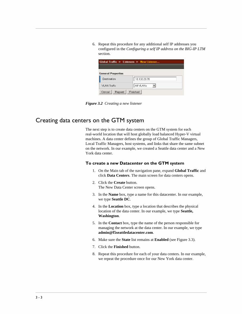
6. Repeat this procedure for any additional self IP addresses you configured in the Configuring a self IP address on the BIG-IP LTM section.
Figure 3.2 Creating a new listener
Creating data centers on the GTM systemThe next step is to create data centers on the GTM system for each real-world location that will host globally load balanced Hyper-V virtual machines. A data center defines the group of Global Traffic Managers, Local Traffic Managers, host systems, and links that share the same subnet on the network. In our example, we created a Seattle data center and a New York data center.
To create a new Datacenter on the GTM system
1. On the Main tab of the navigation pane, expand Global Traffic and click Data Centers. The main screen for data centers opens.
2. Click the Create button.The New Data Center screen opens.
3. In the Name box, type a name for this datacenter. In our example, we type Seattle DC.
4. In the Location box, type a location that describes the physical location of the data center. In our example, we type Seattle, Washington.
5. In the Contact box, type the name of the person responsible for managing the network at the data center. In our example, we type [email protected].
6. Make sure the State list remains at Enabled (see Figure 3.3).
7. Click the Finished button.
8. Repeat this procedure for each of your data centers. In our example, we repeat the procedure once for our New York data center.
3 - 3

Deploying the BIG-IP GTM for Microsoft Hyper-V multi-data center deployments
Figure 3.3 Creating a new GTM data center
Creating the monitorThe next task is to create a monitor on the GTM system. Monitors verify connections on pools and virtual servers and are designed to check the status of a pool or virtual server on an ongoing basis, at a set interval. If a pool or virtual server being checked does not respond within a specified timeout period, or the status of a pool or virtual server indicates that performance is degraded, then the Global Traffic Manager can redirect the traffic to another resource.
In our example, the application running within our Hyper-V virtual machine is an email server, so we create a SMTP monitor. The SMTP monitor issues standard Simple Mail Transport Protocol (SMTP) commands to ensure that the BIG-IP LTM virtual server is available. You can configure a monitor most appropriate for your configuration.
Although it is possible to use the default monitor, we recommend creating a new monitor based off the default monitor, which enables you to configure specific options.
To create a BIG-IP GTM health monitor
1. On the Main tab of the navigation pane, expand Global Traffic and then click Monitors.
2. Click the Create button. The New Monitor screen opens.
3. In the Name box, type a name for the monitor. In our example, we type gtm_smtp
4. From the Type list, select SMTP.
5. Configure the options as applicable for your deployment. In our example, we leave the options at their default levels.
6. Click the Finished button.The new monitor is added to the list.
F5 Deployment Guide 3 - 4

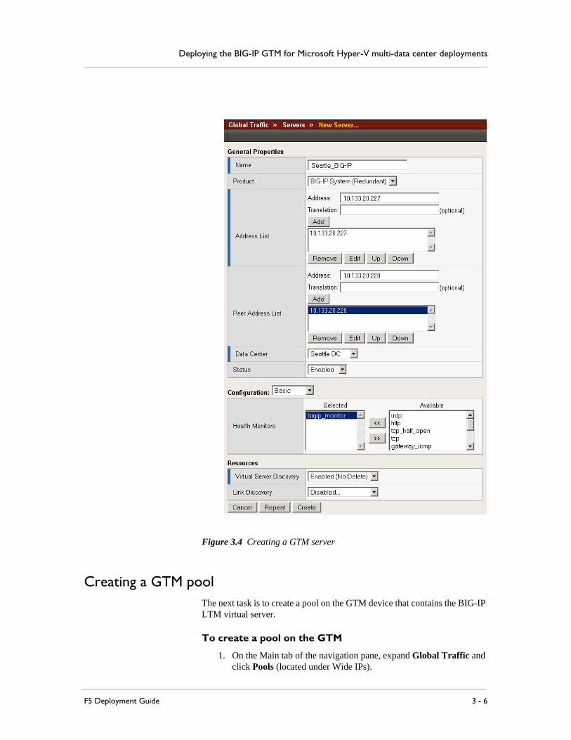
Creating Servers for the data centerThe next task is to create a GTM Server for the data centers. A server defines a specific system on the network. In this deployment, the GTM servers are the BIG-IP LTM systems we configured earlier in this guide.
To create a GTM server
1. On the Main tab of the navigation pane, expand Global Traffic and click Servers.The main screen for servers opens.
2. Click the Create button. The New Server screen opens.
3. In the Name box, type a name that identifies the Local Traffic Manager. In our example, we type Seattle_BIG-IP.
4. From the Product list, select either BIG-IP System (Single) or BIG-IP System (Redundant) depending on your configuration. In our example, we select BIG-IP System (Redundant).
5. From the Address List section, in the Address box, type the self IP address of the BIG-IP LTM device, and then click the Add button. In our example, we type 10.133.20.227.
6. If you selected BIG-IP System (Redundant) in Step 4, from the Peer Address List section, in the Address box, type the self IP address of the redundant BIG-IP LTM device, and then click the Add button.
Note: Do not use a floating IP address of the redundant pair. Do not use the administrative interface of the either member of a redundant pair.
7. From the Data Center list, select the name of the data center you created in the Creating data centers on the GTM system section. In our example, we select Seattle DC.
8. In the Health Monitors section, from the Available list, select the name of the monitor you created in the Creating the monitor section, and click the Add (<<) button. In our example, we select gtm_smtp.
9. In the Resources section, from the Virtual Server Discovery list, choose an option. We recommend Enabled (No Delete). With this option, the GTM will discover all the virtual servers you have configured on the LTM(s) via iControl, and will update, but not delete them.
10. Click the Finished button.
3 - 5
Deploying the BIG-IP GTM for Microsoft Hyper-V multi-data center deployments
Figure 3.4 Creating a GTM server
Creating a GTM poolThe next task is to create a pool on the GTM device that contains the BIG-IP LTM virtual server.
To create a pool on the GTM
1. On the Main tab of the navigation pane, expand Global Traffic and click Pools (located under Wide IPs).
F5 Deployment Guide 3 - 6

2. Click the Create button. The New Pool screen opens.
3. In the Name box, type a name for the pool. In our example, we type Seattle_pool.
4. In the Health Monitors section, from the Available list, select the name of the monitor you created in the Creating the monitor section, and click the Add (<<) button. In our example, we select gtm_smtp.
5. In the Load Balancing Method section, choose the load balancing methods from the lists appropriate for your configuration. In our example, we select Global Availability, Round Robin, and Return to DNS, in that order.
6. In the Member List section, from the Virtual Server list, select the virtual server you created for the Hyper-V hosted application, and click Add. You must select the virtual server by IP Address and port number combination. In our example, we select 10.133.20.200:25.If you have additional virtual servers for the Hyper-V hosted applications configured on the BIG-IP LTM system, repeat this step.
7. Click the Finished button.
Figure 3.5 Creating a pool on the BIG-IP GTM
3 - 7

Deploying the BIG-IP GTM for Microsoft Hyper-V multi-data center deployments
Creating a wide IP on the GTMThe next task is to create a wide IP on the GTM system. A wide IP is a mapping of a fully-qualified domain name (FQDN) to a set of virtual servers that host the domain’s content.
To create a wide IP on the GTM system
1. On the Main tab of the navigation pane, expand Global Traffic and click Wide IPs.
2. Click the Create button. The New Wide IP screen opens.
3. In the Name box, type a name for the Wide IP. In our example, we type mail.example.com.
4. In our example, we are not using any iRules, so we skip the iRule section. Configure as appropriate for your deployment.
5. In the Pools section, from the Load Balancing Method list, select a load balancing method. In our example, we select Global Availability. Global Availability instructs the GTM to select the first pool in the wide IP until it becomes unavailable, at which point it selects the next pool until the first pool becomes available again.
In our example, the GTM sends all incoming email to the first-listed pool, Seattle_pool. If that pool is unavailable, all incoming email is sent to the next-listed pool, NewYork_pool. If you wish to distribute incoming email among multiple pools, select another method, such as Ratio. Consult the online documentation or the product manual for more details about load balancing methods.
6. From the Pool List section, from the Pool list, select the name of the pool you created in the Creating a GTM pool section, and then click the Add button. In our example, we select Seattle_pool.Repeat this step for any additional pools. In our example, we repeat one time for the NewYork_pool.
7. All other settings are optional, configure as appropriate for your deployment.
8. Click the Finished button (see Figure 3.6).
F5 Deployment Guide 3 - 8

Figure 3.6 Creating a new Wide IP on the GTM system
The next task is to add the newly-created Wide IP as an MX record in your DNS system. If using the GTM as your primary DNS system, this is done through the ZoneRunner utility.
Configuring the Wide IP as an MX record using ZoneRunnerThe final task in this configuration is to configure the Wide IP as an MX record in a DNS system. In our example, we are using the GTM system as our primary DNS, and use ZoneRunner to add the Wide IP as an MX record.
The ZoneRunner utility is an advanced feature of the Global Traffic Manager. We highly recommend that you become familiar with the various aspects of BIND and DNS before you use this feature. For in-depth information, we recommend the following resources:
• DNS and BIND, 4th edition, Paul Albitz and Cricket Liu
• The IETF DNS documents, RFC 1034 and RFC 1035
3 - 9
Deploying the BIG-IP GTM for Microsoft Hyper-V multi-data center deployments
• The Internet Systems Consortium web site, http://www.isc.org/index.pl?/sw/bind/
For information on adding the required MX record to other DNS servers, for instance BIND or Microsoft Windows 2007 DNS Service, consult the appropriate product documentation.
To add the Wide IP as an MX record using ZoneRunner
1. On the Main tab of the navigation pane, expand Global Traffic and click ZoneRunner.
2. Click the Create button. The New Resource Record screen opens.
3. From the View list, select a view. In our example, we select external.
4. From the Zone list, select the appropriate zone. In our example, we select example.com
5. In the Name box, type a name for the Resource Record. Make sure the domain for which you are creating an MX record is shown, and note that it must end with a period.
6. In the TTL box, type a number of seconds. In our example, we type 500 (which is the default TTL for our zone).
7. From the Type list, select MX.
8. In the Preference box, type 10. Preference is a numeric value for the preference of this mail exchange host relevant to all other mail exchange hosts for the domain. Lower numbers indicate a higher preference, or priority.In a traditional DNS configuration, you would create multiple MX records with different priorities; however, since you're using GTM to provide true wide-area load balancing, it is only necessary to create a single record in this case.
9. In the Mail Server, enter the name of the Wide IP that you created in Creating a wide IP on the GTM. Make sure that this name also ends with a period. In our example, we type mail.example.com.
10. Click the Finished button (see Figure 3.7).
F5 Deployment Guide 3 - 10

Figure 3.7 Creating a new Resource Record using ZoneRunner
This concludes the BIG-IP GTM configuration. For more information on the BIG-IP GTM, see the GTM documentation.
3 - 11

4
Deploying the BIG-IP WAN Optimization module with Microsoft Hyper-V Servers

Configuring BIG-IP WOM with Microsoft Hyper-V Servers
This chapter describes how to configure the BIG-IP WAN Optimization Module (WOM) to accelerate the transfer of files and reduce bandwidth utilization for Hyper-V deployments.
Because Hyper-V virtual machines are stored as sets of files (primarily a large virtual had disk, or VHD, and any associated snapshots), administrators may easily copy virtual machines over a wide-area network (WAN) to duplicate an application or even an entire data center to a remote location. However, because virtual machines tend to be large -- typically several gigabytes up to many tens of gigabytes -- the time and bandwidth required for these file transfers are often excessive.
By deploying BIG-IP WOM on either end of the WAN, you can accelerate the transfer of files and reduce overall bandwidth utilization, sometimes by dramatic amounts. Although compressibility and cacheability of individual virtual machines will vary greatly depending on operating system and other content and layout, it is not unusual to see a 3x or better improvement in transfer speeds while at the same time seeing a commensurate decrease in overall bandwidth use.
For more information on the WAN Optimization Module, see http://www.f5.com/products/big-ip/product-modules/wan-optimization-module.html
Common ScenariosHyper-V, in standalone mode, supports the use of virtual disks hosted on local storage, or via a SAN (Storage Area Network) using FibreChannel or iSCSI. In a Failover Cluster scenario, highly-available virtual machines can be hosted on clustered storage using FibreChannel or iSCSI.
Because the Hyper-V host is running Windows Server 2008, that host can transfer virtual machine files in any manner typically available to the operating system. Additionally, the storage system may include remote duplication technology. Common scenarios might include some of these options for replicating all of part of a set of virtual disks to remote destination:
◆ The host Windows Server 2008 operating system might use Windows File Sharing (SMB/CIFS), or NFS, to duplicate files across the WAN to another Windows Server 2008 server running Hyper-V.
◆ A storage host might use FTP to copy volumes across the WAN to another remote storage host.
◆ A SAN storage device might use implementation-specific native technologies (e.g. EMC SRDF, or Network Appliance SnapMirror) to duplicate entire volumes or volume changes to remote data centers.
4 - 1

Deploying the BIG-IP WAN Optimization module with Microsoft Hyper-V Servers
Configuring the WAN optimization module First, we configure the WAN optimization module (WOM). The WAN optimization module allows you to encrypt and accelerate data between BIG-IP devices, accelerate applications across the WAN, and much more.
One of the options for initially configuring the WAN optimization module is Dynamic Discovery. The benefit of dynamic discovery is that it reduces configuration complexity. However, when dynamic discovery is used, the BIG-IP currently disables iSession routing in order to prevent inadvertent routing loops. In our environment, dynamic discovery is allowed, but care was taken to ensure iSession routing was enabled.
In this section, we assume you have already configured basic settings such as VLANs and Self-IP address on your BIG-IP systems. If you have not, see the BIG-IP documentation, available on Ask F5 (https://support.f5.com/kb/en-us.html).
Note
The following procedure is only necessary when initially configuring the BIG-IP WOM. If you have already performed the initial configuration, continue with Creating the iSession profile, on page 4-4.
To configure the WOM module
1. On the Main tab of the local BIG-IP system, expand WAN Optimization, and then click Configuration. The Local Endpoint Configuration screen opens.
2. In the IP Address box, type the BIG-IP self IP address you provisioned for iSession endpoint in the data center.
3. Make sure the Create iSession Virtual Server list is set to Yes.
4. Click the Save button.
5. In the Advertised Routes Configuration section, click the Create button. The Advertised Route is the local subnet that the local endpoint advertises to all configured remote endpoints to which it is connected.
6. In the Alias box, type an alias for this route. This is optional. In our example, we type hyper-v-wom.
7. In the Subnet Address box, type the appropriate subnet address. In our example, we type 10.133.20.0.
8. In the Netmask box, type the associated netmask. In our example, we type 255.255.255.0.
9. Make sure the Enabled box is checked.
10. Click the Finished button.
11. In the Dynamic Discovery section, we leave the default settings.
F5 Deployment Guide 4 - 2

12. Repeat this entire procedure on the remote endpoint BIG-IP system, using the appropriate BIG-IP self IP address in step 2, and the appropriate Advertised Route information.
After performing this procedure on both BIG-IP systems, you connect your two BIG-IP systems together via an iSession tunnel by identifying each remote endpoint. If dynamic discovery was left on (as in step 11), you only perform the following procedure on one of the BIG-IP systems. If you did not, you must repeat this procedure on the remote BIG-IP system.
To configure the remote endpoints
1. On the Main tab of the local BIG-IP system, expand WAN Optimization, and then click Configuration.
2. On the Menu bar, click Remote Endpoints.
3. Click the Create button.
4. From the Remote Endpoint list, select Advanced.
5. In the IP Address box, type the IP address you provisioned for remote iSession endpoint.
6. Important: From the Routing list, select Enabled.
7. Click Finished.
8. If you disabled dynamic discovery in the previous procedure, you must repeat this procedure on the remote BIG-IP system.
Figure 4.1 Configuring the remote endpoint
4 - 3
Deploying the BIG-IP WAN Optimization module with Microsoft Hyper-V Servers
Ensuring that iSession routing is enabledAs mentioned previously, if Dynamic Discovery is enabled, the BIG-IP system automatically sets remote endpoint routing to disabled. We want to ensure remote endpoint routing is enabled (as in step 6 above).
Important
We recommend you check that routing is enabled after anytime the BIG-IP system reboots or hotfix/upgrade installations, as routing may revert to Disabled to avoid any routing loops.
To ensure that iSession routing is enabled
1. On the Main tab of the local BIG-IP system, expand WAN Optimization, and then click Configuration.
2. On the Menu bar, click Remote Endpoints.
3. Click the IP address of the appropriate endpoint.
4. From the Routing list, make sure that Enabled is selected. If it is not, select Enabled from the list.
5. Click the Update button.
6. Repeat this procedure on the remote BIG-IP system.
Creating the iSession profileIn this procedure, we create an iSession profile. The iSession profile tells the system how to optimize traffic.
To create the iSession profile
1. On the Main tab, expand Local Traffic, and then click Profiles.
2. On the Menu bar, from the Services menu, select iSession.
3. Click the Create button.
4. In the Name box, type a name for this profile. In our example, we type hyper-v-isession.
5. In our example, we leave all settings at the default levels, which results in data transfers that are optimized using both adaptive compression and deduplication.
6. Click the Finished button.
7. Repeat this on the Remote BIG-IP WAN Optimization module.
Creating the WAN Optimization policyThe next task is to create the WAN optimization policy. For this configuration, we create a new optimization policy for the Hyper-V servers.
F5 Deployment Guide 4 - 4

To create a new WAN Optimization policy
1. On the Main tab, expand WAN Optimization, and then click Configuration.
2. On the Menu bar, click Optimization Policies.
3. Click the Create button. The Common Application Optimization Policies page opens.
4. Click the Create Custom Policy button. The New Optimization Policy wizard opens.
5. Type a name for this virtual server. In our example, we type hyper-v-local.
6. Select No for the question asking if this is an iSession endpoint tunnel terminating virtual server.
7. In the IP address/netmask section, select Network. Type the IP Address and Netmask for the remote network where the Hyper-V member servers are located.
8. In the What kind of application would you like to optimize? box, type the appropriate port number, or select a protocol from the list.
9. From the Will clients be connecting to this virtual server over a LAN list, select Yes.
10. Encrypting the tunneled data is optional. In our example, we select Yes.
11. In the VLAN section, from the Available list, select the appropriate VLANs and click the Add (<<) button.
12. In the Profile Settings section, from the iSession Profile box, select the profile you created in Creating the iSession profile, on page 4.
13. Click the Finished button.
14. Repeat this on the remote BIG-IP WOM, but in Step 7, use the IP address and Netmask for the local network where the Hyper-V servers are located.
Your Hyper-V traffic in either direction is now optimized and encrypted.
4 - 5