microservices and machine learning algorithms for adaptive
TRANSCRIPT

sustainability
Article
Microservices and Machine Learning Algorithms forAdaptive Green Buildings
Diego Rodríguez-Gracia 1, José A. Piedra-Fernández 2,* , Luis Iribarne 2 , Javier Criado 2 ,Rosa Ayala 2, Joaquín Alonso-Montesinos 3 and Capobianco-Uriarte Maria de las Mercedes 4
1 Ministry of Education and Vocational Training, the Andalusian Regional Government, 04008 Almería, Spain2 Applied Computing Group, University of Almería, 04120 Almería, Spain3 Solar Energy Research Centre (CIESOL), University of Almeria, 04120 Almería, Spain4 Economy and Business Department, University of Almería, 04120 Almería, Spain* Correspondence: [email protected]; Tel.: +34-638-14-00-97
Received: 30 May 2019; Accepted: 7 August 2019; Published: 9 August 2019�����������������
Abstract: In recent years, the use of services for Open Systems development has consolidated andstrengthened. Advances in the Service Science and Engineering (SSE) community, promoted bythe reinforcement of Web Services and Semantic Web technologies and the presence of new Cloudcomputing techniques, such as the proliferation of microservices solutions, have allowed softwarearchitects to experiment and develop new ways of building open and adaptable computer systems atruntime. Home automation, intelligent buildings, robotics, graphical user interfaces are some of thesocial atmosphere environments suitable in which to apply certain innovative trends. This paperpresents a schema for the adaptation of Dynamic Computer Systems (DCS) using interdisciplinarytechniques on model-driven engineering, service engineering and soft computing. The proposalmanages an orchestrated microservices schema for adapting component-based software architecturalsystems at runtime. This schema has been developed as a three-layer adaptive transformation processthat is supported on a rule-based decision-making service implemented by means of Machine Learning(ML) algorithms. The experimental development was implemented in the Solar Energy ResearchCenter (CIESOL) applying the proposed microservices schema for adapting home architecturalatmosphere systems on Green Buildings.
Keywords: adaptive systems; machine learning; microservices; smart building
1. Introduction
Some current software systems need to adapt their behavior and structure to new requirementswhich were not identified during the development phase. As a particular type of system,component-based applications are in general defined at design time according to a componentarchitecture and a set of initial requirements. In this sense, it could be useful that some kind of dynamicsystems would be able to analyze, for example, the interaction with users (including profile information)or some changes in the environment, with the purpose of modifying the architecture of such systemsto adapt them at runtime, thus meeting the new requirements. Some dynamic systems include thesefeatures and provide the software with the ability to modify their behavior depending on the executioncircumstances, for example, changes in the user interactions, variations in the available resources,new required values in the quality of service (QoS) properties, changes in the execution platform, etc.The majority of the adaptation capabilities can be identified in the analysis and design stages and,therefore implemented during the development. However, unforeseen circumstances, different tothe original conditions may arise, and it could be necessary for the software system to be adaptedto these new situations. In these cases, it is useful to provide the systems with mechanisms through
Sustainability 2019, 11, 4320; doi:10.3390/su11164320 www.mdpi.com/journal/sustainability

Sustainability 2019, 11, 4320 2 of 22
which they could adapt their behavior automatically. These solutions are known in the literature asSelf-Adaptive Systems (SAS) [1]. Furthermore, this dynamic behavior is obtained in many cases fromthe management of the abstract representations of a system (i.e., models), instead of manipulating thecode that implements it. As a consequence, the static view of the models is being updated by proposalsthat try to adapt the software automatically by manipulating the models that define it.
1.1. Related Work
In the particular domain of component-based software systems, using Model-Driven Engineering(MDE) techniques can facilitate the design and development of architectures, i.e., defining the structure,the behavior of its components and their relationships, interaction or functional and nonfunctionalproperties [2]. Moreover, management architecture models make it possible to generate differentsoftware systems based on the same abstract definition in run-time while the adaptation process isfocusing on user interaction, component status or runtime platform [3].
A lot of research papers, dealing with the dynamic adaptation of software systems (DAS) inruntime context, use architecture based approaches [4,5]. The Rainbow’s [4] framework providesmechanisms to adapt and update the architecture models to the needs of the system using the modelsabstract architecture to monitor, evaluate and adapt the settings then get the system running, in thecontext of mobile applications architectural models can be used to describe the variability, i.e., that themodels themselves contain information and selection criteria for the middleware can derive adaptationruntime context [5]. There are also proposals where variability models are defined to describe the logicand to separate adaptation and system operation [6]. There are works where the authors proposeimplementing an adaptive loop control system as a component-based system [7]. Therefore, the controlloop can be reconfigured at run-time to incorporate new knowledge dynamically. The aim of ourproposal is to develop a similar system in which the logic of adaptation to change as knowledge isgained from the run.
Another type of adaptive systems are dynamic software product lines (DSPL). These systems aresimilar to traditional software product lines but the variability is linked to runtime [8,9]. In Reference [10]the authors apply their use in the domain of home automation (smart homes). In its proposal, variabilitymodels are used to activate or deactivate features at runtime, thus fulfilling the context conditions.
There are proposals for systems that use high level adaptive programming languages for evolution.In Reference [11,12] systems based on Java implementations that run within an OSGi [13] platformfor adapting software at runtime are proposed. In this case, the programs written in programminglanguages are static artifacts and cannot evolve in runtime. Regarding the dynamic compositionmodel transformations, there are studies that propose an incremental way to update the processes oftransformation and construction dynamically from a set of rules [14]. In Reference [15] an approachto the composition of transformations in ATLAS Transformation Language (ATL) is proposed whilein Reference [16] a similar proposal is described using the language of Query/View/Transformation(QVT) transformation. In References [17,18], the authors present a mechanism for building modeltransformations from prebuilt modules that can be referenced or imported from an ATL file.
In our proposal the transformation phase of models is based on these works to define a repositoryof ATL rules which are dynamically selected to build a transformation at runtime.
Other works such as References [19,20] propose an update of the transformations in order to makea refactoring of models to adapt at runtime but do not try to refactor the transformation itself. One ofthe M2M transformations goals is to improve and to adapt their behavior to the context of the systemthrough including new rules or helpers [21]. Following an MDE approach, this refactoring can beimplemented as transformations in which the transformations themselves are involved as input/outputtransformations in so called Higher-Order Transformations (HOT) [22,23]. In our proposed use of HOTto dynamically generate transformations an adaption of the model runtime architecture is carried out.
On the other hand, computational intelligence [24] is a set of technologies consisting of: artificialneural networks, fuzzy systems, evolutionary computation, Bayesian and probabilistic methods, chaos

Sustainability 2019, 11, 4320 3 of 22
theory and “swarm” systems or distributed intelligence. At this point we emphasize that fuzzylogic allows us to treat imprecision, use approximate reasoning and to define more closely to naturallanguage; neural networks focus on learning, adaptation and classification and probabilistic methodsare based on statistical reasoning about evidence. One of the ideas is to use hybrid models wherethe advantages of the learning ability of fuzzy logic and neural networks were combined to form theneural diffusion systems [25]. Currently, the European Center for Soft Computing (ECSC) is a worldleader and main applications are focused on: planning and optimization of industrial productionlines, information and personalized advice to encourage energy savings, the application of cognitivetechnologies in production processes, etc. In the research group Applied Computing has worked inthe field of “soft computing” in image retrieval based on fuzzy content using neuro-fuzzy systemsand Bayesian networks [26] and the definition of a methodology feature selection processes intelligentlearning by Bayesian networks and neuro-fuzzy systems [27]. In the field of software engineeringand computer intelligence we can mainly find applications focused on assessing the cost of reusingcomponents as in References [28,29] where neuro-fuzzy models for classifying component reuse isproposed. Instead our proposal aims to make intelligent model transformations at runtime usingcomputational intelligence techniques that are showing excellent results.
Work on efficiency in energy use and people comfort can be found at the Polytechnic Universityof Bucharest where a control implementation of an intelligent building through the implementationof a mechanism driven by a set of policies under which the heating system is activated [30]. Otherstudies were focused on the implementation of Human-Robot Cloud architectures (HRC) [31] onthe specific scenario of smart building for efficiency gains and energy saving. This paper presentsa proposal whereby sensors, processors and actuators, which include facial identifiers and humanlocators, are transferred to a distributed and reconfigurable cognitive system which can supportmultiple applications in the future.
With regard to the methodologies used to control smart buildings, some proposals are largelybased on the definition of a logical simple inference using the values of different measuring sensorsand presence sensors [32–34]. Other methodologies use techniques of Bayesian inference (Bayesiannetwork) to predict user behavior patterns [35]. An example of this is Reference [36] a method capableof predicting energy consumption per capita. On the other hand, iDorm [37] is presented as an adaptivesystem (able to learn from the interaction with the user and thus predict their future needs) usingembedded agents. These agents use incremental synchronous learning (ISL) based on fuzzy logic.In Reference [38] the use of Markov chains is proposed to establish the likelihood of occupation ofcertain areas. In Reference [34] a comparative study of different methods and techniques used tocontrol smart buildings is presented.
1.2. Objectives
This article proposes a solution to the problem of adapting software systems at runtime. However,this approach is not suitable for all types of systems but is only focused on component-based software.Specifically, the architectures describing the software are built from coarse-grained componentmanaged as black boxes. Therefore, the components which are included in an architecture provide thefunctionality required by the system at a specific time, but due to some changes in the context or otheradaptation purposes, these components must be changed or the architecture reconfigured to adapt thesystem behavior and meet the new requirements.
A main characteristic of our proposal is the abstraction process in the representation of the systems,and in the adaptation, which results in process domain and platform independence. The representationis performed by modeling techniques and the adaptation is addressed using model-to-model (M2M)transformation mechanisms implemented in Atlas Transformation Language (ATL) [39]. In addition,the model transformations are not static, but are built at runtime and can be conformed to the changesin the context, user interaction, new requirements, etc. In the present work, the adaptation mechanismsare provided with a decision-making system and a machine learning process that collect the information

Sustainability 2019, 11, 4320 4 of 22
from the user interactions and the system context, and generates the corresponding adaptation rulesthat will define the system knowledge. These rules are utilized by the adaptation process to performthe corresponding model transformations dynamically at runtime.
1.3. Main Contributions of the Work
In this paper, we illustrate a novel adaptive system and effective way of building open and adaptablecomputer systems at runtime. Specifically, by successfully using interdisciplinary techniques onmodel-driven engineering, service engineering and soft computing, our system achieves the following.
a. Manage a microservices schema for adapting component-based software architectural systemsat runtime. It is very easy to integrate a new components into the system. It is portable to othersystems or buildings.
b. Include Machine learning algorithms in the adaptive transformation as a rule-baseddecision-making service. It is easy to interpret and combines multiple classifiers to find asolution with the least number of rules.
c. Facilitate comfort control and energy savings through the user profiles analyzed onGreen Buildings.
1.4. Outline of This Paper
The paper is structured as follows. Section 2 explains the methodology that supports our approach.A case study applying our approach is presented in Section 3. Finally, Section 4 presents the conclusionsand the indications for future work.
2. Adaptive Models and Systems
This section presents and explains our approach for adapting models of component-basedsoftware systems under a service-oriented architecture. Because these software systems are modeledas component architectures to avoid any misunderstanding, hereinafter we use the term infrastructureto identify our underlying service solution.
The infrastructure supporting the adaptive transformation described in section one has beendeveloped under a Service-Oriented Architecture (SOA) approach [40]. Therefore, all the operationsfrom the adaptation and decision-making subsystems are deployed as small services (or microservices)to be requested locally or remotely, orchestrated through a microservice architecture. Some servicesare related to M2M transformations, for example, the services Context Processing and ArchitecturalTransformation from the adaptation process (Figure 1). Other services form part of the decision-makingprocess, such as the Decision-Making System and the Operation Selection Service. These services maynot be deployed in the same host following a monolithic approach, but they can be distributed indifferent servers following an approach based on microservices [41]. Accordingly, when a client wantsto execute one of the offered functionalities, it may be necessary to orchestrate a set of services so thatthey are executed in a specific order to, for example, obtain an adapted architecture model from aninitial one. As a case study, we apply the adaptive transformation and decision-making subsystems tothe social healthcare and the energy efficiency applied to home automation, in particular, for domoticcontrol in green buildings.

Sustainability 2019, 11, 4320 5 of 22
Sustainability 2019, 11, x FOR PEER REVIEW 5 of 23
Figure 1. A service-oriented adaptive architecture.
As mentioned, the adaptation of systems is addressed as a transformation process at runtime. Additionally, this process is not valid for all types of applications, but is focused on systems that are built from coarse-grained components managed as black boxes. The components present in an architecture determine the system behavior and its properties, satisfying the requirements in a specific time. However, these requirements may change at runtime (e.g., due to changes in the application context) and therefore the architecture should be adapted to meet the new requirements. In our case, adaptation purposes must be accomplished by performing changes in the aforementioned coarse-grained components, for example, inserting a new component, deleting an unnecessary element, varying the association between modules or modifying some configuration properties of the existing components. In addition, component dependencies must be taken into account because they can imply some additional operations. For example, the inclusion of a new Component A into the architecture is subject to the addition of a Component B if the latter resolves some functionality which is required by the former.
Our adaptation process is supported by an infrastructure of services with the goal of building a set of subprocesses in terms of microservices that can solve each atomic operation (those with sufficient entity and which can be used for different purposes) in a separate way. Therefore, we can update the repository of adaptation rules at any time by requesting the corresponding microservice, as a possible example among others. Figure 2 shows the two main services provided by our approach. On the one hand, the Adaptive Transformation Service (a) is composed of a set of microservices implementing a sequence of M2M transformations. On the other hand, the Decision-Making Service (e) is formed by a machine learning solution and generator of transformation rules. As a consequence, the normal behavior of our proposal executes the following steps. The Adaptive Transformation service takes as its inputs: an initial architectural model and the actions performed by the user (b), a model containing the context information required to get the adaptation (c), and the adaptation rules generated by the Decision-Making Service (d). As an output, it generates the adapted architectural model (g). The Decision-Making Service provides the ability to learn from the user and the environment. The acquired knowledge is used for composing the adaptation rules at runtime which provide the system with the capability of generating the architectural model that is best adapted from the initial model (i.e., taking into account the context
Figure 1. A service-oriented adaptive architecture.
As mentioned, the adaptation of systems is addressed as a transformation process at runtime.Additionally, this process is not valid for all types of applications, but is focused on systems thatare built from coarse-grained components managed as black boxes. The components present inan architecture determine the system behavior and its properties, satisfying the requirements ina specific time. However, these requirements may change at runtime (e.g., due to changes in theapplication context) and therefore the architecture should be adapted to meet the new requirements.In our case, adaptation purposes must be accomplished by performing changes in the aforementionedcoarse-grained components, for example, inserting a new component, deleting an unnecessary element,varying the association between modules or modifying some configuration properties of the existingcomponents. In addition, component dependencies must be taken into account because they can implysome additional operations. For example, the inclusion of a new Component A into the architecture issubject to the addition of a Component B if the latter resolves some functionality which is required bythe former.
Our adaptation process is supported by an infrastructure of services with the goal of building aset of subprocesses in terms of microservices that can solve each atomic operation (those with sufficiententity and which can be used for different purposes) in a separate way. Therefore, we can updatethe repository of adaptation rules at any time by requesting the corresponding microservice, as apossible example among others. Figure 2 shows the two main services provided by our approach.On the one hand, the Adaptive Transformation Service (a) is composed of a set of microservicesimplementing a sequence of M2M transformations. On the other hand, the Decision-Making Service(e) is formed by a machine learning solution and generator of transformation rules. As a consequence,the normal behavior of our proposal executes the following steps. The Adaptive Transformationservice takes as its inputs: an initial architectural model and the actions performed by the user (b), amodel containing the context information required to get the adaptation (c), and the adaptation rulesgenerated by the Decision-Making Service (d). As an output, it generates the adapted architecturalmodel (g). The Decision-Making Service provides the ability to learn from the user and the environment.The acquired knowledge is used for composing the adaptation rules at runtime which provide thesystem with the capability of generating the architectural model that is best adapted from the initial

Sustainability 2019, 11, 4320 6 of 22
model (i.e., taking into account the context variables and the user actions). The following subsectionsdescribe the composition and behavior of both main services in detail.
Sustainability 2019, 11, x FOR PEER REVIEW 6 of 23
variables and the user actions). The following subsections describe the composition and behavior of both main services in detail.
Figure 2. The schema of the service-oriented adaptive architecture.
2.1. Adaptive Transformation Service
This service is composed of a set of microservices implementing M2M transformations. The execution of these microservices following a specific sequence results in an adapted architectural model from an initial one. As mentioned, the new architecture is adapted to the user and the context, since the Adaptive Transformation Service receives feedback from the Decision-Making Service. The microservices, the involved resources and the transformation sequence are explained as follows (Figure 3):
Figure 2. The schema of the service-oriented adaptive architecture.
2.1. Adaptive Transformation Service
This service is composed of a set of microservices implementing M2M transformations.The execution of these microservices following a specific sequence results in an adapted architecturalmodel from an initial one. As mentioned, the new architecture is adapted to the user and the context,since the Adaptive Transformation Service receives feedback from the Decision-Making Service.The microservices, the involved resources and the transformation sequence are explained as follows(Figure 3):
• Context Processing Service. This microservice executes an M2M transformation which receivesthe initial architectural model (AMi), the model containing the context variables (OBMi) and themodel with the rules generated by the Decision-Making Service (AAOpDmMi) as its inputs. As aresult, it generates the model of adaptation operations to be executed (AOpDmMi).
• Operation Selection Service. In this microservice, the operations to be executed selected by theuser (AAOpUserMi) are compared to the operations generated by the Context Processing Service(AOpDmMi) through an M2M transformation. In the case that neither match, the operationsselected by the user (AAOpUserMi) will be chosen, thus generating the model of operations thatare going to be executed (AEOpMi).
• Rule Selection Service. This microservice selects the transformation rules from the repository (RRM)that must be executed to accomplish the set of adaptation operations (AEOpMi). The algorithm ofthis service is inspired by the reinforcement learning concept in the sense that it selects those ruleswhich score better from all the available ones. It generates the set of selected transformation rules(RMi) as an output, which will conform the new M2M transformation.
• RSL Service. This consists of an M2M transformation that updates the attributes of the rulerepository (RRM) based on bonus and penalty scores depending on the selected rules (RMi).

Sustainability 2019, 11, 4320 7 of 22
• Rule Transformation Service. This microservice implements a Higher-Order Transformation(HOT) [22,23] which is in charge of translating the selected adaptation rules (RMi) into ATL rulemodel (TMi).
• ATL Extraction. This process executes a Textual Concrete Syntax (TCS) [42] extraction responsiblefor generating the ATL code from the rule model (TMi).
• Architectural Model Transformation Service. Is the M2M transformation created dynamically asresult of the transformation sequence and it is in charge of adapting the initial architectural modelby applying the selected transformation rules.
Sustainability 2019, 11, x FOR PEER REVIEW 7 of 23
Figure 3. Adaptive transformation service schema.
• Context Processing Service. This microservice executes an M2M transformation which receives the initial architectural model (AMi), the model containing the context variables (OBMi) and the model with the rules generated by the Decision-Making Service (AAOpDmMi) as its inputs. As a result, it generates the model of adaptation operations to be executed (AOpDmMi).
• Operation Selection Service. In this microservice, the operations to be executed selected by the user (AAOpUserMi) are compared to the operations generated by the Context Processing Service (AOpDmMi) through an M2M transformation. In the case that neither match, the operations selected by the user (AAOpUserMi) will be chosen, thus generating the model of operations that are going to be executed (AEOpMi).
• Rule Selection Service. This microservice selects the transformation rules from the repository (RRM) that must be executed to accomplish the set of adaptation operations (AEOpMi). The algorithm of this service is inspired by the reinforcement learning concept in the sense that it selects those rules which score better from all the available ones. It generates the set of selected transformation rules (RMi) as an output, which will conform the new M2M transformation.
• RSL Service. This consists of an M2M transformation that updates the attributes of the rule repository (RRM) based on bonus and penalty scores depending on the selected rules (RMi).
• Rule Transformation Service. This microservice implements a Higher-Order Transformation (HOT) [22,23] which is in charge of translating the selected adaptation rules (RMi) into ATL rule model (TMi).
• ATL Extraction. This process executes a Textual Concrete Syntax (TCS) [42] extraction responsible for generating the ATL code from the rule model (TMi).
• Architectural Model Transformation Service. Is the M2M transformation created dynamically as result of the transformation sequence and it is in charge of adapting the initial architectural model by applying the selected transformation rules.
The purpose of Section 2.1 is to summarize the main functionality of the adaptive transformation service. For this reason, we have listed the components and briefly describe their behavior. More details about this service (and its components) are available in previous research work [43–45], which has been included in this section to provide additional explanations.
Figure 3. Adaptive transformation service schema.
The purpose of Section 2.1 is to summarize the main functionality of the adaptive transformationservice. For this reason, we have listed the components and briefly describe their behavior. Moredetails about this service (and its components) are available in previous research work [43–45], whichhas been included in this section to provide additional explanations.
2.2. Decision-Making Service
This service provides the capability of adaptation over time to our approach of architecturaltransformations. It is possible due to the machine learning solution supported by this service, thusthe adaptation rules defined a priori are not static, but can be modified and even new rules can begenerated over time. This learning is the result of processing the user interactions and the changes inthe environment and, as a consequence, the system evolves over time adapting to the users’ behaviorand the variations of the system context. The Decision-Making Service takes (1) the system contextinformation and (2) the adaptation rules executed in the Adaptive Transformation Service (AEOpMi)as its inputs. As an output, it generates the adaptation rules to be executed by the system. Next,the processes that conform the Decision-Making Service and their execution sequence are described(Figure 4):

Sustainability 2019, 11, 4320 8 of 22
Sustainability 2019, 11, x FOR PEER REVIEW 8 of 23
2.2. Decision-Making Service
This service provides the capability of adaptation over time to our approach of architectural transformations. It is possible due to the machine learning solution supported by this service, thus the adaptation rules defined a priori are not static, but can be modified and even new rules can be generated over time. This learning is the result of processing the user interactions and the changes in the environment and, as a consequence, the system evolves over time adapting to the users’ behavior and the variations of the system context. The Decision-Making Service takes (1) the system context information and (2) the adaptation rules executed in the Adaptive Transformation Service (AEOpMi) as its inputs. As an output, it generates the adaptation rules to be executed by the system. Next, the processes that conform the Decision-Making Service and their execution sequence are described (Figure 4):
Figure 4. Decision-Making Service schema.
a: DB Update
This is the process that is executed first. It is initiated when at least one rule has been generated in the model of operations to be executed (AEOpMi). This process receives the model containing the context variables used in the Context Processing Service (OBMi) as inputs and the outputs are generated by the Operation Selection Service. In this process, the knowledge database (Knowledge DB) is updated according to the environment variables (OBMi) and the rules to be executed (AEOpMi).
b: TMT Class
The inputs to this process are the rules generated by the Operation Selection Service, and it generates the classes involved in these rules as an output (Classified Class). Only the attributes and the classes from the Knowledge DB which are meaningful to the possible generation of new rules are processed. Therefore, we avoid the unnecessary processing of records of the database that have been modified in the execution, thus reducing the computing time.
c: Classifier
This process includes the execution of the classifiers of the knowledge database generating the corresponding rules.
This execution includes three subprocesses. The first subprocess is the Feature Selection (Figure 4–6.a). There are the two approaches to perform this selection:
Figure 4. Decision-Making Service schema.
a: DB UpdateThis is the process that is executed first. It is initiated when at least one rule has been generated
in the model of operations to be executed (AEOpMi). This process receives the model containingthe context variables used in the Context Processing Service (OBMi) as inputs and the outputs aregenerated by the Operation Selection Service. In this process, the knowledge database (Knowledge DB)is updated according to the environment variables (OBMi) and the rules to be executed (AEOpMi).
b: TMT ClassThe inputs to this process are the rules generated by the Operation Selection Service, and it
generates the classes involved in these rules as an output (Classified Class). Only the attributes andthe classes from the Knowledge DB which are meaningful to the possible generation of new rules areprocessed. Therefore, we avoid the unnecessary processing of records of the database that have beenmodified in the execution, thus reducing the computing time.
c: ClassifierThis process includes the execution of the classifiers of the knowledge database generating the
corresponding rules.This execution includes three subprocesses. The first subprocess is the Feature Selection
(Figure 4–6.a). There are the two approaches to perform this selection:
• Filter methods: These methods select features by ranking them by means of compression techniques(Principal Components Analysis) or by computing correlation with the output (class).
• Wrapper methods: these methods searching for an optimal subset selection using the classifier.
In the step Feature Selection, a filter method selects features by computing correlation with theoutput. In general, this method is independent of the classification algorithm. The computationalcost is low. Correlation based Feature Selection (CFS) is the algorithm used for this purpose [46].It determines a ranking of the main features. In our case, the subset features are between 100% and 50%of value in the ranking. The next step is responsible for the building the rule model (Figure 4–6.b) andthen this rule model is validated (Figure 4–6.c), i.e., the classifier is trained and evaluated. The resultsobtained from this validation are processed by the Rules Generator operation. This compares thegenerated rule model and the stored rule model with the aim of selecting the one with the best scorefollowing the punctuation criteria defined a priori (Expert’s Knowledge DB). As inputs, this process(Classifier) receives the records about the behavior of the model transformations at runtime and theirinteraction with the environment throughout time (Knowledge DB). In addition, further input is

Sustainability 2019, 11, 4320 9 of 22
formed by the records about the classes involved in the rules generated from the model transformations(Classified Class). This data is reset when the Build Model and Validation processes are finished.The last input of the Classifier process is a database storing the different classifier types that must beexecuted (Classifiers DB). The selection of these classifiers as well as the different parameters associatedwith them (Rhoa, Cross-Validation, etc.) arise from the data preprocessing and are selected by theexperts following the most suitable criteria according to the requirements of the system of modeltransformations at runtime. For the Build Model and Validation processes a Java application hasbeen developed which uses the algorithms and libraries included in the Waikato Environment forKnowledge Analysis platform (WEKA), http://www.cs.waikato.ac.nz/ml/weka/.
d: Rules GeneratorThis process generates the rules to be executed by the Adaptative Transformation Service.
The inputs to the process are:
• The optimal rules generated by the classifier (Classifier Results).• The log of the optimal results obtained from the previous executions of the classifier (Classifier
Results Log).• The criteria and parameters to be compared from the obtained results to be able to perform the
selection from among the generated rules. The selected rules are those that best fit the systemspecifications (Expert´s Knowledge DB). These parameters are defined by the experts. As itsoutput, this process updates the Classifier Results Log and stores the Rules to be executed by theAdaptive Transformation Service only if the obtained results are better than the results stored inthe log (step 9 in Figure 4).
• Actions Selection. A Higher-Order Transformation (HOT) [22,23] in charge of translating theRules generated by the Decision Making into the rules to be executed by the Context ProcessingService (AAOpDmMi).
3. Case Study
For the case study we extend our proposal of Adaptive Domotic System in Green Buildings [45]where we propose a home automation system based on our adaptive architecture of component-baseddevelopment of model transformations at runtime. In Reference [45] we managed to optimize theenergy consumption of the CIESOL building and increase user comfort by adapting the system to theuser preferences. In the present proposal of adaptive control system in green buildings presented inthis work, we focus on two of the three basic factors (thermal comfort, visual comfort, and indoor airquality) that determine the quality of life in buildings [47].
In our study, we intend to develop an adaptive control system based on services in which thethermal comfort and visual comfort within the CIESOL building can be achieved by parameterizingand processing the collected data that are generated from the user’s interaction with the system.Figure 5 shows the adaptation home automation system schema.
In our proposal the decision-making system will generate new adaptation rules using the collecteddata from the sensors and actuators in the building. These rules are defined based on the interactionbetween the user and the home automation system. In fact, these adaptation rules will be transformedinto control rules and added to the system control by the adaptation process.

Sustainability 2019, 11, 4320 10 of 22
Sustainability 2019, 11, x FOR PEER REVIEW 10 of 23
In our study, we intend to develop an adaptive control system based on services in which the thermal comfort and visual comfort within the CIESOL building can be achieved by parameterizing and processing the collected data that are generated from the user’s interaction with the system. Figure 5 shows the adaptation home automation system schema.
In our proposal the decision-making system will generate new adaptation rules using the collected data from the sensors and actuators in the building. These rules are defined based on the interaction between the user and the home automation system. In fact, these adaptation rules will be transformed into control rules and added to the system control by the adaptation process.
Figure 5. Adaptive Domotics system schema.
3.1. The CIESOL Building
The Solar Energy Research Center (CIESOL) was founded and managed according to an agreement between the University of Almeria (Spain) and the Center for Energy, Environment and Technology (CIEMAT) at the Ministry of Economy and Competitiveness (Spain). The center is located in the Campus of the University of Almeria. CIESOL was built using bioclimatic standards and is designed for efficient energy use.
CIESOL engages in research and technology transfer activities in the field of solar energy applications concerning: organometallic photochemistry, water treatment, environmental chemistry, modeling and automatic control of solar systems [48], home automation for energy efficiency, as well as solar cooling and solar resource assessment.
CIESOL (single-store building) encompasses an area of 1100 m2 with 10 laboratories, five offices and a conference room with a maximum occupancy of higher than 75 people.
3.2. Data Acquisition and Preprocessing
The CIESOL building includes a weather station with outdoor and indoor sensors. The data from different sensors are parameterized and collected every minute. The main environmental values are temperature, humidity, radiation and wind speed. In this study, the data are collected by the temperature and movement sensors located in the different rooms of the CIESOL building in the year 2014 during the months of February, May, July and October. These months are the most representative of each season for the city of Almeria and are the months with a higher index of human activity in the different rooms located in the building.
From the data collected we observed that the temperatures measured during working hours (from Monday to Friday, from 8 a.m. to 8 p.m.) in the rooms varied significantly, which shows that the optimal comfort temperature depends on the user preferences and is not a known value a priori.
Figures 6 and 7 show the temperatures measured by the four temperature sensors located in two rooms of the CIESOL building in which we have focused this study. These measurements
Figure 5. Adaptive Domotics system schema.
3.1. The CIESOL Building
The Solar Energy Research Center (CIESOL) was founded and managed according to an agreementbetween the University of Almeria (Spain) and the Center for Energy, Environment and Technology(CIEMAT) at the Ministry of Economy and Competitiveness (Spain). The center is located in theCampus of the University of Almeria. CIESOL was built using bioclimatic standards and is designedfor efficient energy use.
CIESOL engages in research and technology transfer activities in the field of solar energyapplications concerning: organometallic photochemistry, water treatment, environmental chemistry,modeling and automatic control of solar systems [48], home automation for energy efficiency, as wellas solar cooling and solar resource assessment.
CIESOL (single-store building) encompasses an area of 1100 m2 with 10 laboratories, five officesand a conference room with a maximum occupancy of higher than 75 people.
3.2. Data Acquisition and Preprocessing
The CIESOL building includes a weather station with outdoor and indoor sensors. The datafrom different sensors are parameterized and collected every minute. The main environmental valuesare temperature, humidity, radiation and wind speed. In this study, the data are collected by thetemperature and movement sensors located in the different rooms of the CIESOL building in the year2014 during the months of February, May, July and October. These months are the most representativeof each season for the city of Almeria and are the months with a higher index of human activity in thedifferent rooms located in the building.
From the data collected we observed that the temperatures measured during working hours (fromMonday to Friday, from 8 a.m. to 8 p.m.) in the rooms varied significantly, which shows that theoptimal comfort temperature depends on the user preferences and is not a known value a priori.
Figures 6 and 7 show the temperatures measured by the four temperature sensors located in tworooms of the CIESOL building in which we have focused this study. These measurements correspondto the same period of time (second week of February and July, Monday to Friday) in each room.The differences between the temperatures of the rooms can be appreciated when there is humanpresence during working hours. For this reason, the difference between the desired temperaturedepending on the user preferences.

Sustainability 2019, 11, 4320 11 of 22
Sustainability 2019, 11, x FOR PEER REVIEW 11 of 23
correspond to the same period of time (second week of February and July, Monday to Friday) in each room. The differences between the temperatures of the rooms can be appreciated when there is human presence during working hours. For this reason, the difference between the desired temperature depending on the user preferences.
Figure 6. Laboratory 8: temperature measurements.
Figure 7. Laboratory 6: temperature measurements.
In order to obtain information about the air distribution, five sensors were installed at different heights. The idea was to measure directly the fan coil output and the air temperature at different levels to be able to model the behavior and techniques as in studies similar to this one. Therefore, the fan coil was placed in the roof of the laboratory, as it was necessary see how the air flowed down to the ground. The total height of the laboratory is about three meters so, the criterion was to divide the height the laboratory by three equally spaced points. Therefore, three sensors were positioned on a vertical pole to provide information about the air temperature stratification which could be used to model the speed at which a homogeneous temperature was reached in the laboratory. Therefore, with these sensors it was possible to monitor the average temperature in the room and, moreover, the time required to reach the desired temperature throughout the laboratory. This was the main reason to install a sensor in the roof (just in front of the fan coil), which guarantees the direct measure of the fan coil output. Finally, the bottom sensor (placed on the floor) is also used to
Figure 6. Laboratory 8: temperature measurements.
Sustainability 2019, 11, x FOR PEER REVIEW 11 of 23
correspond to the same period of time (second week of February and July, Monday to Friday) in each room. The differences between the temperatures of the rooms can be appreciated when there is human presence during working hours. For this reason, the difference between the desired temperature depending on the user preferences.
Figure 6. Laboratory 8: temperature measurements.
Figure 7. Laboratory 6: temperature measurements.
In order to obtain information about the air distribution, five sensors were installed at different heights. The idea was to measure directly the fan coil output and the air temperature at different levels to be able to model the behavior and techniques as in studies similar to this one. Therefore, the fan coil was placed in the roof of the laboratory, as it was necessary see how the air flowed down to the ground. The total height of the laboratory is about three meters so, the criterion was to divide the height the laboratory by three equally spaced points. Therefore, three sensors were positioned on a vertical pole to provide information about the air temperature stratification which could be used to model the speed at which a homogeneous temperature was reached in the laboratory. Therefore, with these sensors it was possible to monitor the average temperature in the room and, moreover, the time required to reach the desired temperature throughout the laboratory. This was the main reason to install a sensor in the roof (just in front of the fan coil), which guarantees the direct measure of the fan coil output. Finally, the bottom sensor (placed on the floor) is also used to
Figure 7. Laboratory 6: temperature measurements.
In order to obtain information about the air distribution, five sensors were installed at differentheights. The idea was to measure directly the fan coil output and the air temperature at different levelsto be able to model the behavior and techniques as in studies similar to this one. Therefore, the fan coilwas placed in the roof of the laboratory, as it was necessary see how the air flowed down to the ground.The total height of the laboratory is about three meters so, the criterion was to divide the height thelaboratory by three equally spaced points. Therefore, three sensors were positioned on a vertical poleto provide information about the air temperature stratification which could be used to model the speedat which a homogeneous temperature was reached in the laboratory. Therefore, with these sensorsit was possible to monitor the average temperature in the room and, moreover, the time required toreach the desired temperature throughout the laboratory. This was the main reason to install a sensorin the roof (just in front of the fan coil), which guarantees the direct measure of the fan coil output.Finally, the bottom sensor (placed on the floor) is also used to measure the temperature at ground level,which gives us information about the interaction between the ground and the ambient, considering thepossible heat/cold exchange between these two spaces.

Sustainability 2019, 11, 4320 12 of 22
Once the data had been preprocessed, five variables were considered in this study, which woulddefine the state of the fan coil (shutdown, heating, air conditioning) in the different rooms studied,resulting in a total of 60 × 24 × 121 = 174,200 data vectors per room (4638–2.66% data was not usablebecause of the value inconsistency). Figure 8 shows both the location of the fan coil inside and thelocation of the temperature sensors in which we have focused our case study.
Sustainability 2019, 11, x FOR PEER REVIEW 12 of 23
measure the temperature at ground level, which gives us information about the interaction between the ground and the ambient, considering the possible heat/cold exchange between these two spaces.
Once the data had been preprocessed, five variables were considered in this study, which would define the state of the fan coil (shutdown, heating, air conditioning) in the different rooms studied, resulting in a total of 60 × 24 × 121 = 174,200 data vectors per room (4638–2.66% data was not usable because of the value inconsistency). Figure 8 shows both the location of the fan coil inside and the location of the temperature sensors in which we have focused our case study.
We have also extended the scope of our study to control the lights of the rooms. Unfortunately, at the time of developing our proposal there was no record of the values of light intensity inside the rooms as well as the state of the lights (on/off). Therefore, we decided to simulate these parameters taking the same range as the one used for the preprocessing of room temperatures during the months of February, May, July and October, a measurement per minute (24 h a day Monday through Friday) around 174,200 data vectors. For the minimum and maximum illumination level values (lux) we take as a reference the Spanish standard for ergonomic requirements for office work with data visualization screens. In addition, applying energy efficiency criteria establishes a maximum value of lighting level from which the lights will turn off depending on whether there is presence in the room and whatever the preferences of the user since it is considered that artificial lighting is unnecessary. Random values of light intensity, alarm status, motion sensor and on/off status were generated.
Figure 8. The localization of temperature and fan coil sensors. Figure 8. The localization of temperature and fan coil sensors.
We have also extended the scope of our study to control the lights of the rooms. Unfortunately,at the time of developing our proposal there was no record of the values of light intensity inside therooms as well as the state of the lights (on/off). Therefore, we decided to simulate these parameterstaking the same range as the one used for the preprocessing of room temperatures during the monthsof February, May, July and October, a measurement per minute (24 h a day Monday through Friday)around 174,200 data vectors. For the minimum and maximum illumination level values (lux) we takeas a reference the Spanish standard for ergonomic requirements for office work with data visualizationscreens. In addition, applying energy efficiency criteria establishes a maximum value of lighting levelfrom which the lights will turn off depending on whether there is presence in the room and whateverthe preferences of the user since it is considered that artificial lighting is unnecessary. Random valuesof light intensity, alarm status, motion sensor and on/off status were generated.
After preprocessing and analyzing the data, the study variables are shown in Table 1.

Sustainability 2019, 11, 4320 13 of 22
Table 1. Variable Specification.
Abrev. Name Description Data Type
t Ti_Sup_Lab Temperature measured in room (◦C) Numerici LightIntensity Light intensity measured in room (lx) Numerica AlarPresActive Central alarm activated (0, 1) Booleans SenMovLab Motion sensor (0, 1) Booleanm Month Month of the measurements (1, 2, 3, 4) Numericf FANCLab Fan coil Output: 0 Off, 1 Heating and 2 Air Numericl LightsLab Indoor Lights Output: 0 Turn off, 1 Turn on Numeric
The variable s indicates the presence of users in the room. If there is no one (s = 0), both the roomand fan coil lights must be switched off regardless of the values of light intensity (i) or temperature (t)measured in the room (l = 0 and f = 0). The variable a indicates if the central alarm of the CIESOLbuilding is activated or not. If yes (i.e., a = 1) both the room lights and the fan coil should be turnedoff (l = 0 and f = 0) regardless of the values of the movement sensor (s), the light intensity (i) or thetemperature (t).
In order to simplify the study and treatment of the generated rules, the temporal variable ofmeasurement of room temperature (date format: hour: minutes) was transformed into a new variable(Month, m) which indicates the month in (February = 1, May = 2, July = 3, October = 4).
3.3. Data Classification
Our goal is to build an intelligent system for decision-making knowledge based on rules.The classifiers used to generate the rules in our proposal have been selected taking into account thegood results obtained in contexts similar to the ones in our current research and the low computationalcosts. The following subsection will review the classifiers used for the adaptation rules of this proposal.
3.3.1. Standard Classifiers
Different classifiers have been used for the adaptation rules that best fit our adaptive architectureand the results have been compared according to different factors such as the time taken to build themodel, number of rules, correctly and incorrectly classified instances, etc. The following classifiershave been used:
a) The OneR classifier [49] uses the minimum-error attribute for prediction, discretizingnumeric attributes.
b) The NNge classifier [50] is based on the generic algorithm.c) The C4.5 classifier [51] generates a decision tree using entropy.d) The Multilayer Perceptron algorithm (MLP) [52] (artificial neural network) uses back-propagation
to classify our system’s different actions based on prior information.e) The K-nearest neighbors classifier (K-NN) [53] assigns the action of the class of its nearest neighbor.f) The Naive Bayes classifier [54] where it is assumed that all variables are independent of each
other given the class.
3.3.2. Fuzzy Classifier
The idea is to incorporate the fuzzy classifier in the decision-making process to see if it improvesthe success rate with respect to the standard classifiers. Fuzzy Lattice Reasoning (FLR) classifiershave been included in this study due to their reliability in the generation of rules and the goodresults described in other applications. The capacity for learning of this classifier are demonstratedin a real-world application domain. A fuzzy inference system is a technology based on fuzzylogic [55], that generates rules by an induction process. This is a hybrid system such as fuzzy latticeneuro-computing for clustering and classification in different data domains using lattice theory [56].

Sustainability 2019, 11, 4320 14 of 22
The fuzzy lattice reasoning classifier generates rules from the training data in two-step rule inductionand generalization [57]. Four important ideas of fuzzy lattice reasoning can be summarized asfollows [57]:
• The rule induction may be affected by replacing a hyperbox Aj with a larger hyperbox ai Aj, wherethe larger hyperbox is assigned a category label Cj.
• A rule Aj→ Cj; j = 1; L defines a fuzzy set k (x ≤Aj) in the family of hyperboxes such that hyperboxAj corresponds to the core of fuzzy set k (x ≤ Aj).
• Fuzzy lattice reasoning can deal with semantic data and also non-numeric data, e.g., structureddata (graphs).
• A fuzzy lattice reasoning classifier can deal with a missing data value in a constituent lattice Li byreplacing a missing datum with a lattice interval [a, b] such that vi ([a, b]) = vi(θi(a)) + vi(b) ≈ 0.The latter replacement is semantically interpreted as absence of information.
3.4. Results and Discussion
The results obtained after applying the classifiers to the parameters involved in the insidetemperature of the rooms are shown in Table 2. Ten-fold cross-validation was applied to all classifiers.
Table 2. Results obtained after applying the Classifiers.
Classifier TBM NR CCI ICI KS MAE RMSE RAE RRSE
Fan coil
FLR(rhoa 0.5) 0.53 4 72.8374 27.1626 0.2329 0.1811 0.4255 56.117 105.941FLR(rhoa 0.8) 0.7 15 94.0673 5.9327 0.8705 0.0396 0.1989 12.2569 49.5117FLR(rhoa 0.9) 0.88 24 99.9976 0.0024 1 0 0.004 0.0049 0.9883IBK 0.02 - 68.1185 31.8815 0.2663 0.2125 0.461 66.7205 115.6903C4.5 1.34 7 96.6025 3.3975 0.9313 0.0428 0.1218 13.414 30.4927Multilayer Perceptron 159.24 - 99.519 0.481 0.9901 0.004 0.0497 1.2277 12.3844NaiveBayes 0.38 - 97.1492 2.8508 0.9426 0.0455 0.1196 14.1098 29.7878NNge 3.61 6 96.4578 3.5422 0.9287 0.0468 0.1244 14.5182 31.071OneR 0.47 3 70.659 29.341 0.3885 0.1956 0.4423 60.618 110.107
Indoor Lights
FLR(rhoa 0.5) 0.11 4 82.5045 17.4955 0.2842 0.175 0.4183 51.0667 101.0631FLR(rhoa 0.8) 0.18 11 96.3502 3.6498 0.9456 0.0539 0.1329 12.523 28.4825FLR(rhoa 0.9) 0.25 20 99.9989 0.0011 1 0 0.003 0.0038 0.8764IBK 0.01 - 82.1024 17.8976 0.5341 0.181 0.3976 40.0031 81.2386C4.5 1.59 4 98.8795 1.1205 0.9567 0.0321 0.0612 5.2684 10.1256MultilayerPerceptron 181.05 - 99.7729 0.2271 0.9954 0.003 0.0345 0.345 0.8956NaiveBayes 0.74 - 96.6634 3.3366 0.8969 0.0807 0.1671 23.5765 40.3989NNge 1.45 4 97.3552 2.6448 0.9358 0.0545 0.1203 14.3165 30.6898OneR 0.45 13 77.805 22.195 0.0163 0.2219 0.4711 64.8394 113.877
TBM: Time to build the model; NR: Number of Rules; CCI: Correctly Classified Instances; ICI: Incorrectly ClassifiedInstances; KS: Kappa Statistic; MAE: Mean Absolute Error; RMSE: Root Mean Squared Error; RAE: Relative absoluteerror; RRSE: Root Relative Squared Error.
After studying the obtained results, we decided to use the FLR and the C4.5 classifiers in ourstudy because they obtained rules with the smallest computational cost and the highest percentageof correctly classified instances. Applying the classifier Fuzzy Lattice Reasoning (FLR) we obtainexcellent results which can be seen in the accuracy scatter plot (Figure 9). In this graph it can be seenthat the incorrectly classified instances are not significant and that the rules generated are confirmedafter applying the classifier C4.5, meaning there are reference temperatures that match after applyingthe two classifiers and the possible phase in which the fan coil can be (heating, air conditioning) isdetermined by the months of the year (seasons).

Sustainability 2019, 11, 4320 15 of 22
Sustainability 2019, 11, x FOR PEER REVIEW 15 of 23
TBM: Time to build the model; NR: Number of Rules; CCI: Correctly Classified Instances; ICI: Incorrectly Classified Instances; KS: Kappa Statistic; MAE: Mean Absolute Error; RMSE: Root Mean Squared Error; RAE: Relative absolute error; RRSE: Root Relative Squared Error.
After studying the obtained results, we decided to use the FLR and the C4.5 classifiers in our study because they obtained rules with the smallest computational cost and the highest percentage of correctly classified instances. Applying the classifier Fuzzy Lattice Reasoning (FLR) we obtain excellent results which can be seen in the accuracy scatter plot (Figure 9). In this graph it can be seen that the incorrectly classified instances are not significant and that the rules generated are confirmed after applying the classifier C4.5, meaning there are reference temperatures that match after applying the two classifiers and the possible phase in which the fan coil can be (heating, air conditioning) is determined by the months of the year (seasons).
Figure 9. Accuracy dispersion of Fuzzy Lattice Reasoning (FLR) rhoa (0.9) for 4 months.
In our system, priority will be given to the Fuzzy Lattice Reasoning (FLR) classifier because the FLR classifier enables the interpretation of qualitative and imprecise data as well as data from an uncertain source such as in our study case. Furthermore, the format of the generated rules is easily processed for its subsequent storage in the rules model to be performed by the system (AOpDmMi).
Moreover, the C4.5 classifier generates fewer rules to be treated than the FLR classifier, although these rules are harder to treat. For example, in Figure 10 we can see the decision tree generated given the values of Laboratory 6. Taking all this into account and due to the fact the ranks of luminosity (visual comfort) to be examined present a very similar problem to the already processed temperature ranks (thermal comfort), we decided to apply the same classifiers (FLR y C4.5) to the rooms’ lights control data, obtaining the data shown in Table 2.
Figure 9. Accuracy dispersion of Fuzzy Lattice Reasoning (FLR) rhoa (0.9) for 4 months.
In our system, priority will be given to the Fuzzy Lattice Reasoning (FLR) classifier because theFLR classifier enables the interpretation of qualitative and imprecise data as well as data from anuncertain source such as in our study case. Furthermore, the format of the generated rules is easilyprocessed for its subsequent storage in the rules model to be performed by the system (AOpDmMi).
Moreover, the C4.5 classifier generates fewer rules to be treated than the FLR classifier, althoughthese rules are harder to treat. For example, in Figure 10 we can see the decision tree generated giventhe values of Laboratory 6. Taking all this into account and due to the fact the ranks of luminosity(visual comfort) to be examined present a very similar problem to the already processed temperatureranks (thermal comfort), we decided to apply the same classifiers (FLR y C4.5) to the rooms’ lightscontrol data, obtaining the data shown in Table 2.
From observing the rules generated by the FLR y C4.5 classifiers it can be perceived that there is adifferent comfort temperature for each room (user):
• Lab 6: Reference temperature = 24◦ ± 1◦
• Lab 8: Reference temperature = 23◦ ± 1◦
Furthermore, the status of the fan coil (heating or air conditioner) depends on the months ofthe year, so that the air conditioning is not activated in the month of February and the heating is notactivated during the months not belonging to the winter season (May, July, October).
Similarly, applying the classifiers to the data generated by the simulator, one can perceive thatthe threshold for turning the lights on and off (visual comfort) in Laboratory 6 is 532 lx and 663 lxrespectively, while the threshold in Laboratory 8 is 582 lx and 704 lx respectively. Unlike the rulesgenerated from the actual results measured in the CIESOL building, one can appreciate that the monthis not an influential factor, because the user’s visual comfort zone will depend on the lighting level orluminance of the room, regardless of the time of year. An example of the rules generated by means ofthe FLR classifier is shown below:
R1: {f = 1↔, t8[14.67, 22.98] ∧ (s8) ∧ (¬a) ∧ (m = 1)}
R2: {f = 2↔, t8[23.99, 29.98] ∧ (s8) ∧ (¬a) ∧ (m = 3)}
R3: {f = 0↔, t8[23.99, 29.98] ∧ (¬s8) ∧ (¬a) ∧ (m = 3)|}

Sustainability 2019, 11, 4320 16 of 22
R4: {f = 2↔, t6[24.99, 30.98] ∧ (s6) ∧ (¬a) ∧ (m = 3)}
R5: {l = 10↔, i6[532,663] ∧ (s6) ∧ (¬a)}
R6: {l = 10↔, i8[582,704] ∧ (s8) ∧ (¬a)}Sustainability 2019, 11, x FOR PEER REVIEW 16 of 23
Figure 10. Decision tree generated with C4.5 algorithm.
From observing the rules generated by the FLR y C4.5 classifiers it can be perceived that there is a different comfort temperature for each room (user):
• Lab 6: Reference temperature = 24° ± 1° • Lab 8: Reference temperature = 23° ± 1°
Furthermore, the status of the fan coil (heating or air conditioner) depends on the months of the year, so that the air conditioning is not activated in the month of February and the heating is not activated during the months not belonging to the winter season (May, July, October).
Similarly, applying the classifiers to the data generated by the simulator, one can perceive that the threshold for turning the lights on and off (visual comfort) in Laboratory 6 is 532 lx and 663 lx respectively, while the threshold in Laboratory 8 is 582 lx and 704 lx respectively. Unlike the rules generated from the actual results measured in the CIESOL building, one can appreciate that the month is not an influential factor, because the user’s visual comfort zone will depend on the lighting level or luminance of the room, regardless of the time of year. An example of the rules generated by means of the FLR classifier is shown below:
R1: {f = 1 ↔, t8[14.67, 22.98] ∧ (s8) ∧ (¬a) ∧ (m = 1)}
R2: {f = 2 ↔, t8[23.99, 29.98] ∧ (s8) ∧ (¬a) ∧ (m = 3)}
R3: {f = 0 ↔, t8[23.99, 29.98] ∧ (¬s8) ∧ (¬a) ∧ (m = 3)}
R4: {f = 2 ↔, t6[24.99, 30.98] ∧ (s6) ∧ (¬a) ∧ (m = 3)}
R5: {l = 10 ↔, i6[532,663] ∧ (s6) ∧ (¬a)}
R6: {l = 10 ↔, i8[582,704] ∧ (s8) ∧ (¬a)}
The rule model to be run by the Adaptive Transformation Service, is built from the evaluation of the rules generated by the classifiers. This way, once the processing of the study data is
Figure 10. Decision tree generated with C4.5 algorithm.
The rule model to be run by the Adaptive Transformation Service, is built from the evaluation ofthe rules generated by the classifiers. This way, once the processing of the study data is completed,our system has been loaded with the necessary parameters to obtain the adaptive transformation inthe CIESOL building’s home automation system as described below:
• Knowledge data base (Knowledge DB). Stores the registers used in the data preprocessingpreviously described. It will be updated over time as the user executes different actions to theones generated by the decision-making system.
• Rule model to be executed by the system (AOpDmMi). The rule model in which the rulesgenerated by the classifiers in the data processing, are stored. This will be updated over time withthe new rules generated in the Decision-Making Service.
• Classifiers DB. Stores the classifiers that have been selected as most suitable in the processing aswell as its parameters (Rhoa, validation, etc.) In the case study of the CIESOL building, these willbe the FLR and C4.5 classifiers.
• Expert’s Knowledge DB. Stores the criteria and parameters to be compared with the resultsobtained after applying the corresponding classifier in order to select from among the generatedrules, those rules that best suit the corresponding criteria. For this case study (CIESOL) thefollowing initial comparison criteria have been selected:
- Correctly Classified Instances. The success rate allows us to identify the amount of casestagged correctly by a classifier.
- Kappa statistic measures randomness in the observed proportion of frequencies whencategorizing qualitative variables.

Sustainability 2019, 11, 4320 17 of 22
- Mean absolute error and Relative Absolute Error. The absolute and relative errors give usan idea of the imprecision of the provided data classification.
• The following secondary comparison criteria will be taken into account: (a) The classifier’sgeneration time and (b) the time to classify an instance (i.e., number of rules or depth of the tree).
• Classifier Results Log. To store the register of the results according to the parameters stored in theExpert´s Knowledge DB and obtained during any of the previous times the classifier has beenrun. In our case study the obtained results are those shown in Table 2 for Correctly ClassifiedInstances, Kappa statistic, Mean absolute error, Relative Absolute Error, Time taken (to generateclassifier) and Time taken (to classify an instance).
In order to validate the adaptive capacity of our architecture proposal, we decided to proceedin two steps. As a first approach, we decided to measure the adaptation capacity of our proposal inthe case of a user’s change of behavior. In order to simulate this behavioral change of the user visualcomfort, we used a function in Java to randomly change n times (n = 10.000) the registers (KnowledgeDB) of Laboratory 6 decreasing 10 lx (LightIntensityLab6 = 522 lx) the minimum light intensity valueat which the lights in the room would switch on (LightsLab = 1) taking into account the value of therest of the attributes involved in the rule (MovSenLab6 and AlarActivePres). Then we proceeded tolaunch our system by means of simulation and concluded the system adapted itself to user’s behavior(visual comfort) adjusting the rule that determines the status of the lights inside Laboratory 6 deletingthe existing rule and generating this new Rule 5:
R5: {l = 10↔, i6[532,663] ∧ (s6) ∧ (¬a)}
In a second approach we set out to test the adaptive capacity of our proposal in the case of possiblechanges in the system’s hardware composition (components, sensors). For this test we worked onthe assumption that an actuator was added to the system that would be able to open and close theblinds along with a sensor to provide feedback about the status of this actuator. In accordance withour proposal, the actuator would be a new component (SunblindLab) added to the system and thesensor (BlindSenLab) would be a new variable of the system’s context (Table 3).
Table 3. New Variable Specification.
Abrev. Attribute Name SunBind Description Data Type
b BlindSenLab Close (0,1) Booleann SunblindLab Output: 1 Open/0 no action required Numeric
We defined the values of these variables in a way that the blinds of the room could only be opened(SunblindLab = 1) when the blinds are closed (BlindSenLab = 1). After defining the new contextvariable (attribute) and the new system component (class)and using a function in Java, we proceededto modify the registers of the data base (Knowledge DB) in which the value of the component LightsLab were defined by the prior rule (Rule5) so that when the light intensity value (LightIntensityLab6,i6) of the room is found to be outside the user’s comfort range (visual comfort), in the case the blindsof the rooms are closed, they will open. In the case they are already open, the lights inside the roomwill switch on. After applying these adjustments we proceeded as in the previous case, running oursystem by means of simulation and as a result the previous rule was changed (Rule 5) and a new rulewas generated (Rule 6) as the system successfully adapted to the new system component as well as tothe new requirements that rule its behavior, which is shown below.
R5: {n = 1↔, i6[522,663] ∧ (s6) ∧ (¬a) ∧ (b = 1)}R6: {l = 1↔, i6 [522,663] ∧ (s6) ∧ (¬a) ∧ (b = 0)}
Sustainability 2019, 11, 4320 18 of 22
Obviously the new requirements introduced into the system would not be complements for a realhome automation control system, since the status of the room blinds (open/closed) should take intoaccount the light intensity outside and, based on this value, change its state to open only in the casethat the light intensity were higher than the light intensity of the room and it were inside the user’svisual comfort range determined by the system. However, the purpose of the described simulation isto ascertain the adaptive capacity of our architectural proposal considering the incorporation of newcomponents and requirements into the control system, not the development of complex rules for adomotics control system, which is absolutely feasible with our current architectural proposal.
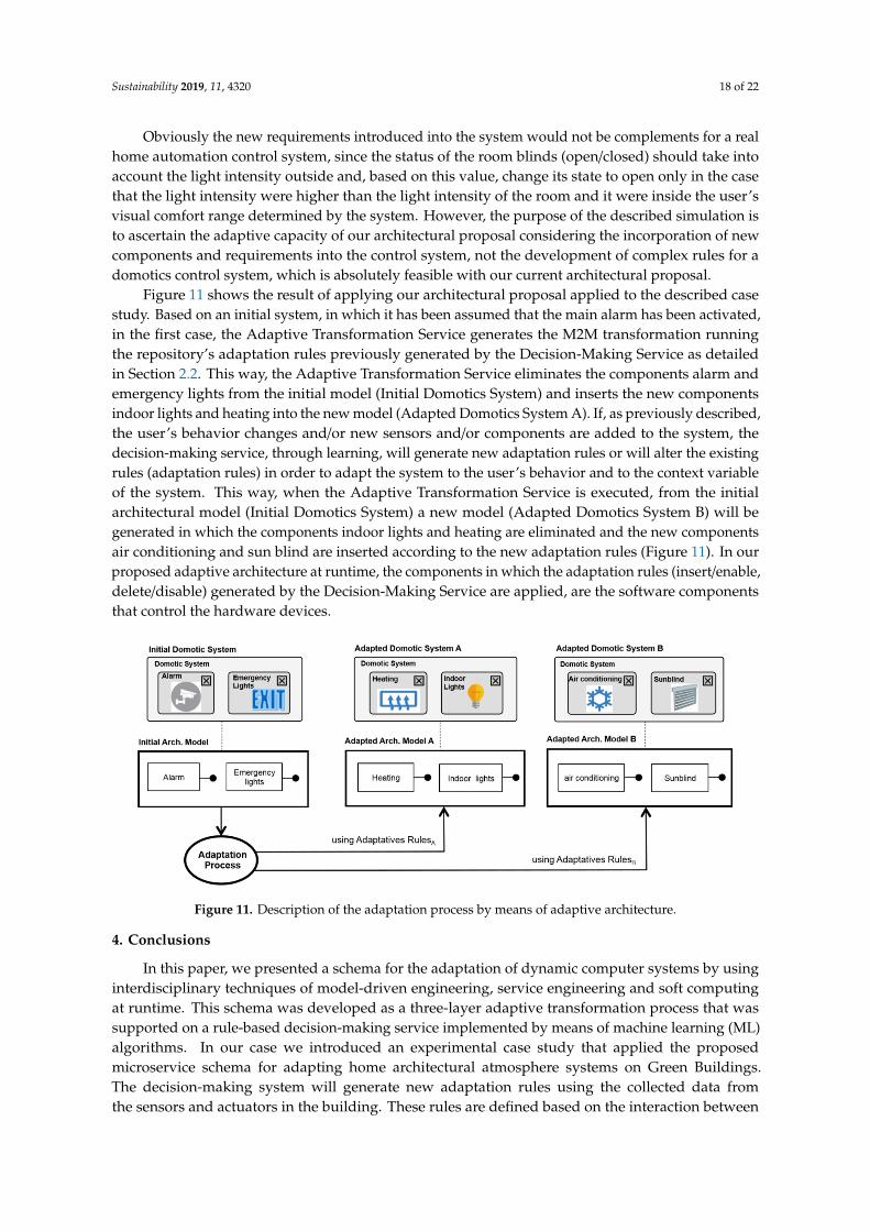
Figure 11 shows the result of applying our architectural proposal applied to the described casestudy. Based on an initial system, in which it has been assumed that the main alarm has been activated,in the first case, the Adaptive Transformation Service generates the M2M transformation runningthe repository’s adaptation rules previously generated by the Decision-Making Service as detailedin Section 2.2. This way, the Adaptive Transformation Service eliminates the components alarm andemergency lights from the initial model (Initial Domotics System) and inserts the new componentsindoor lights and heating into the new model (Adapted Domotics System A). If, as previously described,the user’s behavior changes and/or new sensors and/or components are added to the system, thedecision-making service, through learning, will generate new adaptation rules or will alter the existingrules (adaptation rules) in order to adapt the system to the user’s behavior and to the context variableof the system. This way, when the Adaptive Transformation Service is executed, from the initialarchitectural model (Initial Domotics System) a new model (Adapted Domotics System B) will begenerated in which the components indoor lights and heating are eliminated and the new componentsair conditioning and sun blind are inserted according to the new adaptation rules (Figure 11). In ourproposed adaptive architecture at runtime, the components in which the adaptation rules (insert/enable,delete/disable) generated by the Decision-Making Service are applied, are the software componentsthat control the hardware devices.Sustainability 2019, 11, x FOR PEER REVIEW 19 of 23
Figure 11. Description of the adaptation process by means of adaptive architecture.
4. Conclusions
In this paper, we presented a schema for the adaptation of dynamic computer systems by using interdisciplinary techniques of model-driven engineering, service engineering and soft computing at runtime. This schema was developed as a three-layer adaptive transformation process that was supported on a rule-based decision-making service implemented by means of machine learning (ML) algorithms. In our case we introduced an experimental case study that applied the proposed microservice schema for adapting home architectural atmosphere systems on Green Buildings. The decision-making system will generate new adaptation rules using the collected data from the sensors and actuators in the building. These rules are defined based on the interaction between the user and the home automation system in the CIESOL building. In fact, the solution presented equips the domotic system of CIESOL with the ability to adapt to the behavior of the user integrating a learning system into the domotic system, achieving an improvement in the system’s energetic efficiency and increasing user comfort by adapting the system to the preferences of the user, thus freeing the latter from controlling the components involved in the system. In fact, these adaptation rules will be transformed into control rules and added to the system control by the adaptation process.
As discussed in Section 1, our proposal as a solution to the problem of adapting software systems at runtime is not suitable for all types of systems but is only focused on component-based software. Specifically, the architectures describing the software are built from coarse-grained component managed as black boxes.
We can also say that our proposal is scalable because, although in the case study only temperature and light intensity were considered as comfort variables in order to limit the study, should we decide to consider other variables such as CO2 concentration, air pollutants, indoor airflow, humidity, etc. the system would not require any changes. It would only be necessary to identify the classifier that generates the best results with this new variable and, if this classifier had not already been identified in the case study we developed (FLR and C4.5), the new classifier would only have to be stored (IBK, OneR, etc.) in Classifiers DB for the Decision-Making Service to be able to generate new adaptation rules to be executed by the system.
Moreover, our approach can be applied to different types of software systems where the runtime adaptation of component-based architectures is required. Some examples of these kinds of architectures are related to home automation [10], smart cars [58], smart buildings [59], robotics [60], communication networks [4] or adaptive user interfaces [43].
Future Work
In future work, we will research new big data techniques that improve the optimization of the energy consumption and increase user comfort. Additionally, we aim to validate this approach in
Figure 11. Description of the adaptation process by means of adaptive architecture.
4. Conclusions
In this paper, we presented a schema for the adaptation of dynamic computer systems by usinginterdisciplinary techniques of model-driven engineering, service engineering and soft computingat runtime. This schema was developed as a three-layer adaptive transformation process that wassupported on a rule-based decision-making service implemented by means of machine learning (ML)algorithms. In our case we introduced an experimental case study that applied the proposedmicroservice schema for adapting home architectural atmosphere systems on Green Buildings.The decision-making system will generate new adaptation rules using the collected data fromthe sensors and actuators in the building. These rules are defined based on the interaction between

Sustainability 2019, 11, 4320 19 of 22
the user and the home automation system in the CIESOL building. In fact, the solution presentedequips the domotic system of CIESOL with the ability to adapt to the behavior of the user integrating alearning system into the domotic system, achieving an improvement in the system’s energetic efficiencyand increasing user comfort by adapting the system to the preferences of the user, thus freeing thelatter from controlling the components involved in the system. In fact, these adaptation rules will betransformed into control rules and added to the system control by the adaptation process.
As discussed in Section 1, our proposal as a solution to the problem of adapting software systemsat runtime is not suitable for all types of systems but is only focused on component-based software.Specifically, the architectures describing the software are built from coarse-grained component managedas black boxes.
We can also say that our proposal is scalable because, although in the case study only temperatureand light intensity were considered as comfort variables in order to limit the study, should we decideto consider other variables such as CO2 concentration, air pollutants, indoor airflow, humidity, etc.the system would not require any changes. It would only be necessary to identify the classifier thatgenerates the best results with this new variable and, if this classifier had not already been identified inthe case study we developed (FLR and C4.5), the new classifier would only have to be stored (IBK,OneR, etc.) in Classifiers DB for the Decision-Making Service to be able to generate new adaptationrules to be executed by the system.
Moreover, our approach can be applied to different types of software systems where the runtimeadaptation of component-based architectures is required. Some examples of these kinds of architecturesare related to home automation [10], smart cars [58], smart buildings [59], robotics [60], communicationnetworks [4] or adaptive user interfaces [43].
Future Work
In future work, we will research new big data techniques that improve the optimization of theenergy consumption and increase user comfort. Additionally, we aim to validate this approach inscenarios other than the smart buildings and domotic systems selected for this case study. Therefore,we intend to establish a formal methodology to be able to apply our proposal in any type of dynamiccomputer system that can be represented as architectures of coarse-grained components. In this sense,the methodology should include a protocol to define the available components and the set of adaptationrules depending on the context information and the behavior required. Furthermore, we aim to extendthe amount of data stored that is related to relevant context information so that, in later stages, big datatechniques that improve the optimization of the energy consumption and increase user comfort canbe applied.
Author Contributions: Conceptualization, D.R.-G. and J.A.P.-F.; Methodology, D.R.-G.; Software, D.R.-G.;Validation, D.R.-G., J.A.P.-F. and J.C.; Formal Analysis, J.A.P.-F. and L.I.; Resources, R.A. and J.A.-M.; Data Curation,J.C. and J.A.-M.; Writing—Original Draft Preparation, D.R.-G.; Writing—Review and Editing, C.-U.M.d.l.M.;Visualization, C.-U.M.d.l.M.; Supervision, L.I.; Project Administration, L.I.
Funding: This work was funded by the EU ERDF and the Spanish Ministry of Economy and Competitiveness(MINECO) under AEI Project TIN2017-83964-R.
Acknowledgments: We thank our colleagues from the Solar Energy Research Centre (CIESOL) and the researchgroups TEP-165 and TEP-197, who provided data and expertise that greatly assisted the research.
Conflicts of Interest: The authors declare no conflict of interest.
References
1. Cheng, B.H.C.; de Lemos, R.; Geise, H.; Inverardi, P.; Magee, J. Software Engineering for self-adaptivesystems: A research roadmap. In Software Engineering for Self-Adaptive Systems; Springer: Berlin/Heidelberg,Germany, 2009; pp. 1–26.
2. Crnkovic, I.; Sentilles, S.; Vulgarakis, A.; Chaudron, M.R.V. A Classification Framework for SoftwareComponent Models. IEEE Trans. Softw. Eng. 2011, 3737, 593–615. [CrossRef]

Sustainability 2019, 11, 4320 20 of 22
3. Bencomo, N.; Blair, G. Using Architecture Models to Support the Generation and Operation ofComponent-Based Adaptive System. In Software Engineering for Self-Adaptive Systems; Springer:Berlin/Heidelberg, Germany, 2009; pp. 183–200.
4. Garlan, D.; Cheng, S.; Huang, A.; Schmerl, B.; Steenkiste, P. Rainbow: Architecture-Based Self-Adaptationwith Reusable Infrastructure. Computer 2004, 3737, 46–54. [CrossRef]
5. Floch, J.; Hallsteinsen, S.; Stav, E.; Eliassen, F.; Lund, K.; GjÃÿrven, E. Using Architecture Models for RuntimeAdaptability. IEEE Softw. 2006, 23, 62–70. [CrossRef]
6. Fleurey, F.; Solberg, A. A Domain Specific Modeling Language Supporting Specification, Simulation andExecution of Dynamic Adaptive Systems. In Proceedings of the 12th International Conference on ModelDriven Engineering Languages and Systems (MoDELS’09), Denver, CO, USA, 4–9 October 2009; pp. 606–621.
7. Perrouin, G.; Morin, B.; Chauvel, F.; Fleurey, F.; Klein, J.; Le Traon, Y.; Barais, O.; Jezequel, J.M. TowardsFlexible Evolution of Dynamically Adaptive Systems. In Proceedings of the 34th IEEE InternationalConference on Software Engineering (ICSE’12), Zurich, Switzerland, 2–9 June 2012; pp. 1353–1356.
8. Hallsteinsen, S.; Hinchey, M.; Park, S.; Schmid, K. Dynamic Software Product Lines. Computer 2008, 41, 93–95.[CrossRef]
9. Hinchey, M.; Park, S.; Schmid, K. Building Dynamic Software Product Lines. Computer 2012, 45, 22–26.[CrossRef]
10. Cetina, C.; Giner, P.; Fons, J.; Pelechano, V. Autonomic Computing through Reuse of Variability Models atRuntime: The Case of Smart Homes. Computer 2009, 42, 37–43. [CrossRef]
11. Irmert, F.; Fischer, T.; Meyer-Wegener, K. Run time Adaptation in a Service Oriented Component Model.In Proceedings of the Workshop on Software Engineering for Adaptive and Self-Managing Systems(SEAMS’08), Leipzig, Germany, 12–13 May 2008; pp. 97–104.
12. Serral, E.; Valderas, P.; Pelechano, V. Supporting runtime system evolution to adapt to user behavior.In Proceedings of the International Conference on Advanced Information Systems Engineering, Hammamet,Tunisia, 7–9 June 2010; pp. 378–392.
13. OSGi Alliance. OSGi Service Platform Service Platform Service Compendium, 1st ed.; OSGI Alliance: San Ramon,CA, USA, 2007; pp. 2–698.
14. Hearnden, D.; Lawley, M.; Raymond, K. Incremental Model Transformation for the Evolution of Model-DrivenSystems. In Proceedings of the 9th International Conference on Model Driven Engineering Languages andSystems (MoDELS’06), Genova, Italy, 1–6 October 2006; pp. 321–335.
15. Kurtev, I.; van den Berg, K.; Jouault, F. Rule-based modularization in model transformation languagesillustrated with ATL. Sci. Comput. Program. 2007, 68, 138–154. [CrossRef]
16. Belaunde, M. Transformation Composition in QVT. In Proceedings of the 1st European Workshop Compositionof Model Transformations (CMT’06), Bilbao, Spain, 10 July 2006; pp. 39–45.
17. Wagelaar, D.; Van Der Straeten, R.; Deridder, D. Module superimposition: A composition technique forrule-based model transformation languages. Softw. Syst. Model. 2010, 9, 285–309. [CrossRef]
18. Wagelaar, D.; Tisi, M.; Cabot, J.; Jouault, F. Towards a general composition semantics for rule-based modeltransformation. In Proceedings of the 14th International Conference on Model Driven Engineering Languagesand Systems (MoDELS’11), Wellington, New Zealand, 16–21 October 2011; pp. 623–637.
19. Porres, I. Rule-based update transformations and their application to model refactorings. Softw. Syst. Model.2005, 4, 368–385. [CrossRef]
20. Kolovos, D.S.; Paige, R.F.; Polack, F.; Rose, L.M. Update Transformations in the Small with the Epsilon WizardLanguage. J. Object Technol. 2007, 6, 53–69. [CrossRef]
21. Wimmer, M.; Martínez, S.; Jouault, F.; Cabot, J. A Catalogue of Refactorings for Model-to-ModelTransformations. J. Object Technol. 2012, 11, 1–40. [CrossRef]
22. Tisi, M.; Jouault, F.; Fraternali, P.; Ceri, S.; Bezivin, J. On the Use of Higher Order Model Transformations.In Proceedings of the 5th European Conference on Model Driven Architecture Foundations and Applications(ECMDA’09), Enschede, The Netherlands, 23–26 June 2009; pp. 18–33.
23. Tisi, M.; Cabot, J.; Jouault, F. Improving Higher-Order Transformations Supporting ATL. In Proceedings ofthe 3rd International Conference on Model Transformation (ICMT’10), Málaga, Spain, 28 June–2 July 2010;pp. 215–229.
24. Bonissone, P.P. Soft computing: The convergence of emerging reasoning technologies. Soft Comput. 1997, 1,6–18. [CrossRef]

Sustainability 2019, 11, 4320 21 of 22
25. Abraham, A. Neuro fuzzy systems: State-of-the-art modeling techniques. In Connectionist Models of Neurons,Learning Processes, and Artificial Intelligence; Springer: Berlin/Heidelberg, Germany, 2001; pp. 269–276.
26. Piedra-Fernández, J.A.; Cantón-Garbín, M.; Wang, J.Z. Feature selection in AVHRR ocean satellite images bymeans of filter methods. IEEE Trans. Geosci. Remote Sens. 2010, 48, 4193–4203. [CrossRef]
27. Piedra-Fernández, J.A.; Cantón-Garbín, M.; Wang, J.Z. Fuzzy Content-Based Image Retrieval for OceanicRe-mote Sensing. IEEE Trans. Geosci. Remote Sens. 2013, 52, 5422–5431. [CrossRef]
28. Parvinder, S.S.; Hardeep, S. Automatic Reusability Appraisal of Software Components using Neuro FuzzyApproach. Int. J. Inf. Technol. 2006, 3, 209–214.
29. Harpreet, S.; Vishal, K.T. Neuro Fuzzy Logic Model for Component Based Software Engineering. Int. J.Eng. Sci. 2011, 1, 303–314.
30. Carutasiu, M.; Tanasiev, V.; Ionescu, C.; Danu, A.; Necula, H.; Badea, A. Reducing energy consumption inlow energy buildings through implementation of a policy system used in automated heating systems. EnergyBuild. 2015, 94, 227–239. [CrossRef]
31. Mavridis, N.; Pierris, G.; Ben Abdelkader, C.; Krstikj, A.; Karaiskos, C. Smart buildings and thehuman-machine cloud. In Proceedings of the 2015 IEEE 8th GCC Conference & Exhibition (GCCCE),Muscat, Oman, 1–4 February 2015; pp. 1–6.
32. Agarwal, Y.; Balaji, B.; Gupta, R.; Lyles, J.; Wei, M.; Weng, T. Occupancy driven energy management forsmart building automation. In Proceedings of the 2nd ACM Workshop on Embedded Sensing Systems forEnergy-Efficiency in Building, Zurich, Switzerland, 3–5 November 2010; pp. 1–6.
33. Marchiori, A.; Han, Q. Distributed wireless control for building energy management. In Proceedings of the2nd ACM Workshop on Embedded Sensing Systems for Energy-Efficiency in Building, Zurich, Switzerland,3–5 November 2010; pp. 37–42.
34. Nguyen, T.A.; Aiello, M. Energy intelligent buildings based on user activity: A survey. Energy Build. 2013,56, 244–257. [CrossRef]
35. Harris, C.; Cahill, V. Exploiting user behaviour for context-aware power management, Wireless And MobileComputing. In Proceedings of the IEEE International Conference on Wireless and Mobile Computing,Networking and Communications (WiMob’2005), Montreal, QC, Canada, 22–14 August 2005; Volume 4,pp. 122–130.
36. Hawarah, L.; Ploix, S.; Jacomino, M. User behavior prediction in energy consumption in housing usingBayesian networks. In Proceedings of the 10th International Conference on Artificial Intelligence and SoftComputing, Zakopane, Poland, 13–17 June 2010; pp. 372–379.
37. Hagras, H.; Callaghan, V.; Colley, M.; Clarke, G.; Pounds, A.; Duman, H. Creating an ambient-intelligenceenvironment using embedded agents. IEEE Intell. Syst. 2004, 19, 12–20. [CrossRef]
38. Dodier, R.H.; Henze, G.P.; Tiller, D.K.; Guo, X. Building occupancy detection through sensor belief networks.Energy Build. 2006, 38, 1033–1043. [CrossRef]
39. Jouault, F.; Allilaire, F.; Bezivin, J.; Kurtev, I. ATL: A model transformation tool. Sci. Comput. Program. 2008,72, 31–39. [CrossRef]
40. Erl, T. Service-Oriented Architecture: Concepts, Technology, and Design, 1st ed.; Pearson Education, Inc.:Crawfordsville, IN, USA, 2005; pp. 2–51. ISBN 0-13-185858-0.
41. Newman, S. Building Microservices: Designing Fine-Grained Systems, 1st ed.; O’Reilly Media, Inc.: Sebastopol,CA, USA, 2015; pp. 2–251. ISBN 978-1-491-95035-7.
42. Jouault, F.; Bézivin, J.; Kurtev, I. TCS: A DSL for the specification of textual concrete syntaxes in modelengineering. In Proceedings of the 5th International Conference on Generative Programming and ComponentEngineering (GPCE’06), Portland, OR, USA, 22–26 October 2006; pp. 249–254.
43. Criado, J.; Rodriguez-Gracia, D.; Iribarne, L.; Padilla, N. Toward the Adaptation of Component-basedArchitectures by Model Transformation: Behind Smart User Interfaces. Softw. Pract. Exp. 2015, 45, 1677–1718.[CrossRef]
44. Rodríguez-Gracia, D.; Criado, J.; Iribarne, L.; Padilla, N. A Collaborative testbed Web Tool for Learning ModelTransformation in Software Engineering Education. Comput. Hum. Behav. 2015, 51, 734–741. [CrossRef]
45. Rodriguez-Gracia, D.; Piedra, J.A.; Iribarne, L. Adaptive Domotic System in Green Buildings. In Proceedingsof the 4th IIAI International Congress on Advanced Applied Informatics (IIAI AAI 2015), Okayama, Japan,12–16 July 2015; IEEE Press: Piscataway, NJ, USA, 2015.

Sustainability 2019, 11, 4320 22 of 22
46. Mital, D. Correlation based feature selection CFS technique to predict student performance. Int. J. Comput.Netw. Commun. 2014, 6, 197–206.
47. Dounis, A.I.; Caraiscos, C. Advanced control systems engineering for energy and comfort management in abuilding environment. A review. Renew. Sustain. Energy Rev. 2009, 13, 1246–1261. [CrossRef]
48. Alonso-Montesinos, J.; Batlles, F.J.; Bosch, J.L. Beam: Diffuse and global solar irradiance estimation withsatellite imagery. Energy Convers. Manag. 2015, 105, 1205–1212. [CrossRef]
49. Holte, R.C. Very simple classification rules perform well on most com-monly used datasets. Mach. Learn.1993, 11, 63–91. [CrossRef]
50. Martin, B. Instance-Based Learning: Nearest Neighbour with Generalisation. Ph.D. Thesis, University ofWaikato, Hamilton, New Zealand, 1995.
51. Quinlan, J.R. C4.5: Programs for Machine Learning, 1st ed.; Morgan Kaufmann: Burlington, MA, USA, 1993;Volume 1.
52. Minsky, M.; Papert, S. An Introduction to Computational Geometry, 1st ed.; MIT Press: Boston, MA, USA, 1987.53. Aha, D.; Kibler, D.; Albert, M. Instance-based learning algorithms. Mach. Learn. 1991, 6, 37–66. [CrossRef]54. John, G.; Langley, P. Estimating continuous distributions in Bayesian classifiers. In Proceedings of the 11th
Conference on Uncertainty in Artificial Intelligence, Montréal, QC, Canada, 18–20 August 1995; pp. 338–345.55. Kaburlasos, V.G.; Kehagias, A. Novel fuzzy inference system (FIS) analysis and design based on lattice theory.
IEEE Trans. Fuzzy Syst. 2007, 15, 243–260. [CrossRef]56. Petridis, V.; Kaburlasos, V. Clustering and classification in structured data domains using Fuzzy Lattice
Neuro-computing (FLN). IEEE Trans. Knowl. Data Eng. 2001, 13, 245–260. [CrossRef]57. Kaburlasos, V.G.; Athanasiadis, I.N.; Mitkas, P.A. Fuzzy lattice reasoning (FLR) classifier and its application
for ambient ozone estimation. Int. J. Approx. Reason. 2007, 45, 152–188. [CrossRef]58. Sun, J.; Zhang, Y.P.; Fan, J. Towards a Context-aware Middleware in Smart Car Space. In Proceedings of the
4th International Conference on Genetic and Evolutionary Computing, Shenzhen, China, 13–15 December2010; pp. 276–279.
59. Fouquet, F.; Morin, B.; Fleurey, F.; Barais, O.; Plouzeau, N.; Jezequel, J.M. A Dynamic Component Model forCyber Physical Systems. In Proceedings of the 15th Symposium on Component Based Software Engineering(CBSE’12), Bertinoro, Italy, 25–28 June 2012; pp. 135–144.
60. Inglés-Romero, J.F.; Vicente-Chicote, C.; Morin, B.; Barais, O. Towards the Automatic Generation ofSelf-Adaptive Robotics Software: An Experience Report. In Proceedings of the 20th IEEE InternationalWorkshops on Enabling Technologies: Infrastructure for Collaborative Enterprises (WETICE’11), Paris,France, 27–29 June 2011; pp. 79–86.
© 2019 by the authors. Licensee MDPI, Basel, Switzerland. This article is an open accessarticle distributed under the terms and conditions of the Creative Commons Attribution(CC BY) license (http://creativecommons.org/licenses/by/4.0/).