microporous and mesoporous materialsinorg.hanyang.ac.kr/img/43mmm2012.pdfdate show the...
TRANSCRIPT

Microporous and Mesoporous Materials 150 (2012) 32–37
Contents lists available at SciVerse ScienceDirect
Microporous and Mesoporous Materials
journal homepage: www.elsevier .com/locate /micromeso
Effect of pore structures on selective gas sorption behavior of ultramicroporousMOFs
Narae Jin, Jinwoo Seo, Keunil Hong, Hyungphil Chun ⇑Department of Applied Chemistry, College of Science and Technology, Hanyang University, 1271, Sa-3 dong, Ansan 426-791, Republic of Korea
a r t i c l e i n f o
Article history:Received 8 April 2011Received in revised form 8 July 2011Accepted 9 September 2011Available online 20 September 2011
Keywords:Metal–organic frameworkCoordination polymerCrystal structureSelective sorptionAdsorption isotherm
1387-1811/$ - see front matter � 2011 Elsevier Inc. Adoi:10.1016/j.micromeso.2011.09.017
⇑ Corresponding author. Tel.: +82 31 400 5506; faxE-mail address: [email protected] (H. Chun).
a b s t r a c t
Synthesis, crystal structures and selective gas sorption properties of two new MOFs based on pyrimidyl-5-carboxylate (pmc) are reported. [Co3Cl4(pmc)2(CH3OH)4] (1) possesses pillared layer-type network andnarrow one-dimensional channels. In [Fe3(O)(pmc)5.3(O2CH)0.7]�DMF (2), the trinuclear basic carboxylateunits form a uninodal 5-connected network with isolated cage-like pores. 1 Shows the selective sorptionof hydrogen against nitrogen at 77 K and CO2 against CH4 at 195 K. For 2, a selective sorption is observedonly at 77 K, and the sorption is almost indiscriminate at 195 K. This difference is believed to originatefrom the different pore structures of 1 and 2.
� 2011 Elsevier Inc. All rights reserved.
1. Introduction
The facile synthesis, highly crystalline nature and vast struc-tural diversities of metal–organic frameworks (MOFs) are unparal-leled advantages in materials science and promise a systematicstudy through which new materials with novel properties can bediscovered. For example, such possibilities as biological imagingor delivery agents [1–3], gas-permeation membranes [4–10] andheat storage materials [11,12] have recently been added to the listof more conventional applications for porous MOFs, namely catal-ysis, storage, separation and others [13–26]. We note that most ofthese potential applications are pertinent to the regularly devel-oped voids within host frameworks. Therefore, it is important tounderstand the interactions of various guests with pores of differ-ent sizes and dimensions.
With minor exceptions [27–32], most porous MOFs known todate show the characteristics of microporous materials which aredefined by the International Union of Pure and Applied Chemistry(IUPAC) [33]. Especially, porous MOFs with smaller microporeswhich are often classified as ultramicroporous materials are highlyinteresting. Ultramicroporous materials are those with the freepassage of pores smaller than the bilayer thickness of typicaladsorptive, nitrogen molecules (�7 Å) [34]. In such cases, the diffu-sion of adsorptive molecules inside the pore channels plays animportant role because the adsorption of the first monolayer or afew strongly adsorbed molecules at the pore entrance will prohibit
ll rights reserved.
: +82 31 400 5457.
or significantly slow down further adsorption processes. Therefore,porous MOFs may show the selective sorption of small gases evenwhen the free openings are larger than the kinetic diameters ofadsorptive molecules [35–38].
In order to better understand this interesting phenomenon andutilize it for practical purposes, such as the separation or storage ofindustrially important gases, attentions have to be paid not only onthe topology underlying the framework, but on the structure ofpore itself and its relationship to bulk properties. Our recent effortson MOFs showing unusual gas sorption behavior have been alongthis line [39–41].
In this work we synthesized two new ultramicroporous MOFsthat possess narrow 1D channels or isolated cage-like voids, andcharacterized the framework and pore structures using X-ray crys-tallography on single-crystals. The results of gas sorption studiesreveal that these materials show selective sorption behavior thatreflects the geometry of the pores.
2. Experimental
2.1. General
All the reagents and solvents, unless noted, were commerciallyavailable and used as received. IR data were recorded on KBr pel-lets using a Varian FTS 1000 instrument. TGA data were obtainedon a SCINCO S-1000 instrument with a heating rate of 5 �C min�1
in air. The X-ray powder diffraction (XRPD) patterns were recordedon a Rigaku D/MAX-2500/PC equipped with a Cu sealed tube(k = 1.54178 Å).
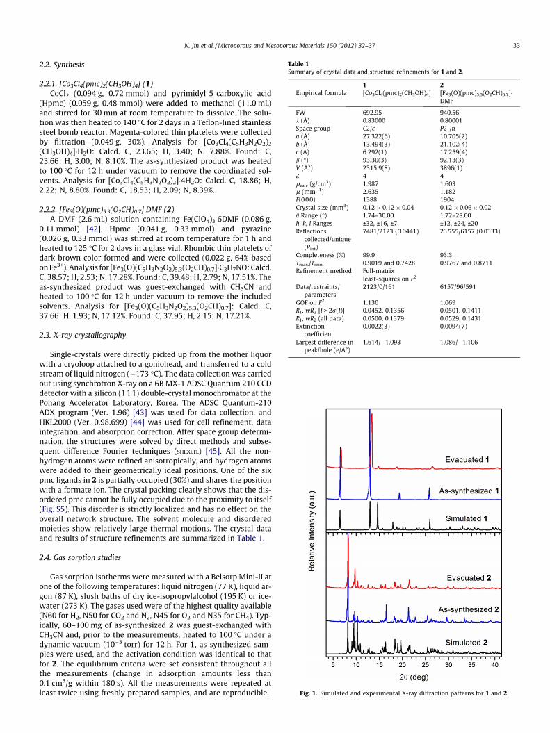
Table 1Summary of crystal data and structure refinements for 1 and 2.
1 2Empirical formula [Co3Cl4(pmc)2(CH3OH)4] [Fe3(O)(pmc)5.3(O2CH)0.7]�
DMF
FW 692.95 940.56k (Å) 0.83000 0.80001Space group C2/c P21/na (Å) 27.322(6) 10.705(2)b (Å) 13.494(3) 21.102(4)c (Å) 6.292(1) 17.259(4)b (�) 93.30(3) 92.13(3)V (Å3) 2315.9(8) 3896(1)Z 4 4qcalc (g/cm3) 1.987 1.603l (mm�1) 2.635 1.182F(000) 1388 1904Crystal size (mm3) 0.12 � 0.12 � 0.04 0.12 � 0.06 � 0.02h Range (�) 1.74–30.00 1.72–28.00h, k, l Ranges ±32, ±16, ±7 ±12, ±24, ±20Reflections
collected/unique(Rint)
7481/2123 (0.0441) 23555/6157 (0.0333)
Completeness (%) 99.9 93.3Tmax./Tmin. 0.9019 and 0.7428 0.9767 and 0.8711Refinement method Full-matrix
least-squares on F2
Data/restraints/parameters
2123/0/161 6157/96/591
GOF on F2 1.130 1.069R1, wR2 [I > 2r(I)] 0.0452, 0.1356 0.0501, 0.1411R1, wR2 (all data) 0.0500, 0.1379 0.0529, 0.1431Extinction
coefficient0.0022(3) 0.0094(7)
Largest difference inpeak/hole (e/Å3)
1.614/�1.093 1.086/�1.106
Fig. 1. Simulated and experimental X-ray diffraction patterns for 1 and 2.
N. Jin et al. / Microporous and Mesoporous Materials 150 (2012) 32–37 33
2.2. Synthesis
2.2.1. [Co3Cl4(pmc)2(CH3OH)4] (1)CoCl2 (0.094 g, 0.72 mmol) and pyrimidyl-5-carboxylic acid
(Hpmc) (0.059 g, 0.48 mmol) were added to methanol (11.0 mL)and stirred for 30 min at room temperature to dissolve. The solu-tion was then heated to 140 �C for 2 days in a Teflon-lined stainlesssteel bomb reactor. Magenta-colored thin platelets were collectedby filtration (0.049 g, 30%). Analysis for [Co3Cl4(C5H3N2O2)2
(CH3OH)4]�H2O: Calcd. C, 23.65; H, 3.40; N, 7.88%. Found: C,23.66; H, 3.00; N, 8.10%. The as-synthesized product was heatedto 100 �C for 12 h under vacuum to remove the coordinated sol-vents. Analysis for [Co3Cl4(C5H3N2O2)2]�4H2O: Calcd. C, 18.86; H,2.22; N, 8.80%. Found: C, 18.53; H, 2.09; N, 8.39%.
2.2.2. [Fe3(O)(pmc)5.3(O2CH)0.7]�DMF (2)A DMF (2.6 mL) solution containing Fe(ClO4)3�6DMF (0.086 g,
0.11 mmol) [42], Hpmc (0.041 g, 0.33 mmol) and pyrazine(0.026 g, 0.33 mmol) was stirred at room temperature for 1 h andheated to 125 �C for 2 days in a glass vial. Rhombic thin platelets ofdark brown color formed and were collected (0.022 g, 64% basedon Fe3+). Analysis for [Fe3(O)(C5H3N2O2)5.3(O2CH)0.7]�C3H7NO: Calcd.C, 38.57; H, 2.53; N, 17.28%. Found: C, 39.48; H, 2.79; N, 17.51%. Theas-synthesized product was guest-exchanged with CH3CN andheated to 100 �C for 12 h under vacuum to remove the includedsolvents. Analysis for [Fe3(O)(C5H3N2O2)5.3(O2CH)0.7]: Calcd. C,37.66; H, 1.93; N, 17.12%. Found: C, 37.95; H, 2.15; N, 17.21%.
2.3. X-ray crystallography
Single-crystals were directly picked up from the mother liquorwith a cryoloop attached to a goniohead, and transferred to a coldstream of liquid nitrogen (�173 �C). The data collection was carriedout using synchrotron X-ray on a 6B MX-1 ADSC Quantum 210 CCDdetector with a silicon (111) double-crystal monochromator at thePohang Accelerator Laboratory, Korea. The ADSC Quantum-210ADX program (Ver. 1.96) [43] was used for data collection, andHKL2000 (Ver. 0.98.699) [44] was used for cell refinement, dataintegration, and absorption correction. After space group determi-nation, the structures were solved by direct methods and subse-quent difference Fourier techniques (SHEXLTL) [45]. All the non-hydrogen atoms were refined anisotropically, and hydrogen atomswere added to their geometrically ideal positions. One of the sixpmc ligands in 2 is partially occupied (30%) and shares the positionwith a formate ion. The crystal packing clearly shows that the dis-ordered pmc cannot be fully occupied due to the proximity to itself(Fig. S5). This disorder is strictly localized and has no effect on theoverall network structure. The solvent molecule and disorderedmoieties show relatively large thermal motions. The crystal dataand results of structure refinements are summarized in Table 1.
2.4. Gas sorption studies
Gas sorption isotherms were measured with a Belsorp Mini-II atone of the following temperatures: liquid nitrogen (77 K), liquid ar-gon (87 K), slush baths of dry ice-isopropylalcohol (195 K) or ice-water (273 K). The gases used were of the highest quality available(N60 for H2, N50 for CO2 and N2, N45 for O2 and N35 for CH4). Typ-ically, 60–100 mg of as-synthesized 2 was guest-exchanged withCH3CN and, prior to the measurements, heated to 100 �C under adynamic vacuum (10�3 torr) for 12 h. For 1, as-synthesized sam-ples were used, and the activation condition was identical to thatfor 2. The equilibrium criteria were set consistent throughout allthe measurements (change in adsorption amounts less than0.1 cm3/g within 180 s). All the measurements were repeated atleast twice using freshly prepared samples, and are reproducible.
34 N. Jin et al. / Microporous and Mesoporous Materials 150 (2012) 32–37
3. Results and discussion
3.1. Synthesis
The title compounds are synthesized by solvothermal reactionsin a fair yield when the suitable sources of metal ions are used, co-balt(II) chloride and iron(III) perchlorate DMF solvate. The com-pounds are formulated as [Co3Cl4(pmc)2(CH3OH)4] (1) and[Fe3(O)(pmc)5.3(O2CH)0.7]�DMF (2) based on X-ray diffraction andother analysis. The formate ligand in 2 is derived from the thermaldecomposition of DMF. The reactions are reproducible, and thepurity and homogeneity of the products have been confirmed byelemental analysis and X-ray powder diffraction (XRPD) studiesin which a number of strong diffraction peaks appear at positionsexpected from the simulation based on single-crystal structures(Fig. 1).
3.2. Crystal structures
The title compounds crystallize as flakes (1) or very small poly-hedra (2). Therefore, we were not able to obtain processable X-raydiffraction data from a conventional tube source, and had to rely onsynchrotron X-rays at the Pohang Accelerator Laboratory, Pohang,Korea, for structural characterizations.
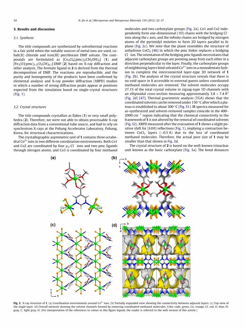
The crystallographic asymmetric unit of 1 contains three octahe-dral Co2+ ions in two different coordination environments. Both Co1and Co2 are coordinated by four l2-Cl� ions and two pmc ligandsthrough nitrogen atoms, and Co3 is coordinated by four methanol
Fig. 2. X-ray structure of 1. (a) Coordination environments around Co2+ ions. (b) Partiallthe single layer. (d) Overall network showing the solvent channels formed by removinggray, C; light gray, H. (For interpretation of the references to colour in this figure legend
molecules and two carboxylate groups (Fig. 2a). Co1 and Co2 inde-pendently form one-dimensional (1D) chains with the bridging Cl�
ions along the c axis, and the infinite chains are bridged by nitrogenatoms of the pyrimidyl moieties to form 2D layers parallel to bcplane (Fig. 2c). We note that the plane resembles the structure ofanhydrous CoCl2 [46] in which the pmc linker replaces a bridgingCl� ion. The orientation of the bridging pmc ligands necessitates thatadjacent carboxylate groups are pointing away from each other in adirection perpendicular to the layer. Finally, the carboxylate groupsof neighboring layers bind solvated Co2+ ions in a monodentate fash-ion to complete the interconnected layer-type 3D network of 1(Fig. 2b). The analysis of the crystal structure reveals that there isno void space in 1 accessible to external guests unless coordinatedmethanol molecules are removed. The solvent molecules occupy27.1% of the total crystal volume in zigzag-type 1D channels withan ellipsoidal cross-section measuring approximately 3.8 � 7.4 Å2
(Fig. 2d) [47]. Thermal gravimetric analysis (TGA) shows that thecoordinated solvents can be removed under 150 �C after which a pla-teau is established to about 300 �C (Fig. S1). IR spectra measured foras-synthesized and solvent-removed samples coincide in the 400–2000 cm�1 region indicating that the chemical connectivity in theframework of 1 is not altered by the removal of coordinated solvents(Fig. S2). XRPD measured after the evacuation of 1 shows a slight po-sitive shift for (h00) reflections (Fig. 1), implying a contraction be-tween CoCl2 layers (�0.5 Å) due to the loss of coordinatedmethanol molecules. Therefore, the actual pore size of 1 may besmaller than that shown in Fig. 2d.
The crystal structure of 2 is based on the well-known trinuclearunit known as the basic carboxylate (Fig. 3a). The bond distances
y expanded view showing the connectivity between adjacent layers. (c) Top view ofcoordinated methanol molecules. Color code: green, Co; orange, Cl; red, O; blue, N;, the reader is referred to the web version of this article.)
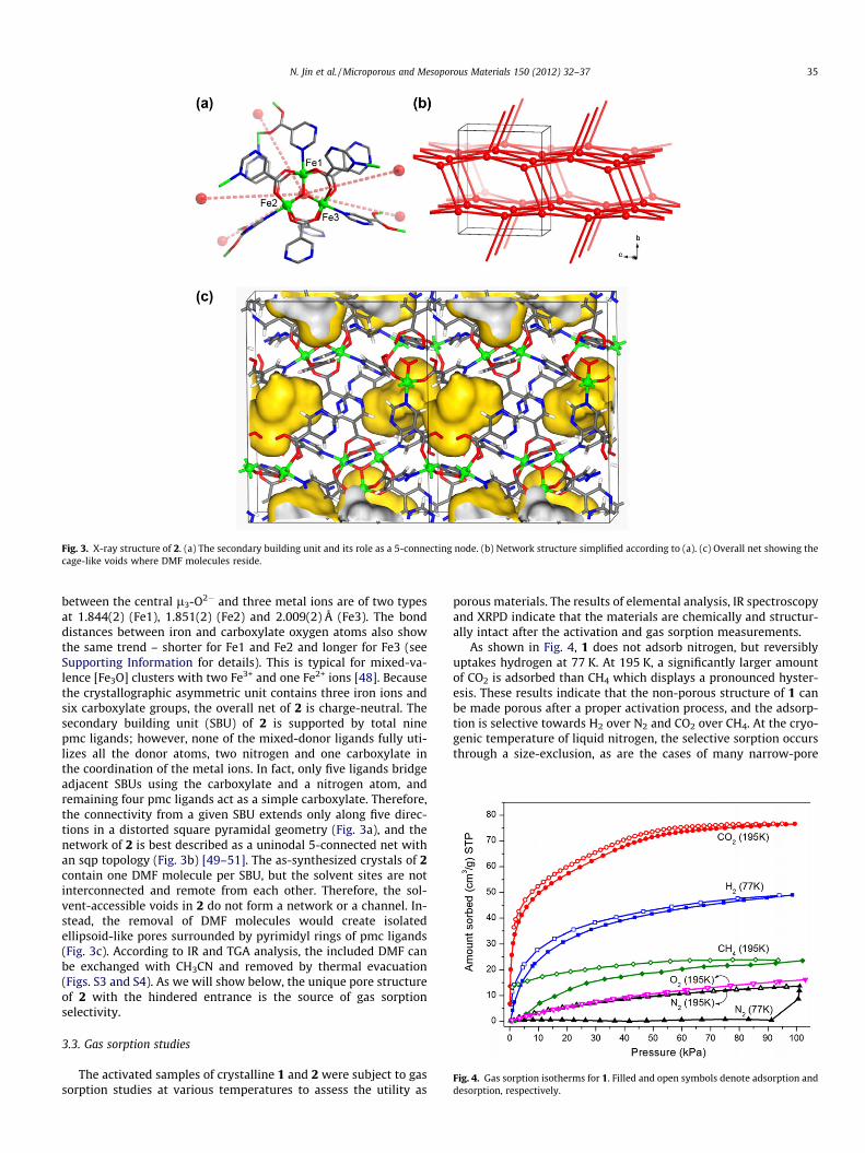
Fig. 3. X-ray structure of 2. (a) The secondary building unit and its role as a 5-connecting node. (b) Network structure simplified according to (a). (c) Overall net showing thecage-like voids where DMF molecules reside.
Fig. 4. Gas sorption isotherms for 1. Filled and open symbols denote adsorption anddesorption, respectively.
N. Jin et al. / Microporous and Mesoporous Materials 150 (2012) 32–37 35
between the central l3-O2� and three metal ions are of two typesat 1.844(2) (Fe1), 1.851(2) (Fe2) and 2.009(2) Å (Fe3). The bonddistances between iron and carboxylate oxygen atoms also showthe same trend – shorter for Fe1 and Fe2 and longer for Fe3 (seeSupporting Information for details). This is typical for mixed-va-lence [Fe3O] clusters with two Fe3+ and one Fe2+ ions [48]. Becausethe crystallographic asymmetric unit contains three iron ions andsix carboxylate groups, the overall net of 2 is charge-neutral. Thesecondary building unit (SBU) of 2 is supported by total ninepmc ligands; however, none of the mixed-donor ligands fully uti-lizes all the donor atoms, two nitrogen and one carboxylate inthe coordination of the metal ions. In fact, only five ligands bridgeadjacent SBUs using the carboxylate and a nitrogen atom, andremaining four pmc ligands act as a simple carboxylate. Therefore,the connectivity from a given SBU extends only along five direc-tions in a distorted square pyramidal geometry (Fig. 3a), and thenetwork of 2 is best described as a uninodal 5-connected net withan sqp topology (Fig. 3b) [49–51]. The as-synthesized crystals of 2contain one DMF molecule per SBU, but the solvent sites are notinterconnected and remote from each other. Therefore, the sol-vent-accessible voids in 2 do not form a network or a channel. In-stead, the removal of DMF molecules would create isolatedellipsoid-like pores surrounded by pyrimidyl rings of pmc ligands(Fig. 3c). According to IR and TGA analysis, the included DMF canbe exchanged with CH3CN and removed by thermal evacuation(Figs. S3 and S4). As we will show below, the unique pore structureof 2 with the hindered entrance is the source of gas sorptionselectivity.
3.3. Gas sorption studies
The activated samples of crystalline 1 and 2 were subject to gassorption studies at various temperatures to assess the utility as
porous materials. The results of elemental analysis, IR spectroscopyand XRPD indicate that the materials are chemically and structur-ally intact after the activation and gas sorption measurements.
As shown in Fig. 4, 1 does not adsorb nitrogen, but reversiblyuptakes hydrogen at 77 K. At 195 K, a significantly larger amountof CO2 is adsorbed than CH4 which displays a pronounced hyster-esis. These results indicate that the non-porous structure of 1 canbe made porous after a proper activation process, and the adsorp-tion is selective towards H2 over N2 and CO2 over CH4. At the cryo-genic temperature of liquid nitrogen, the selective sorption occursthrough a size-exclusion, as are the cases of many narrow-pore

36 N. Jin et al. / Microporous and Mesoporous Materials 150 (2012) 32–37
MOFs [52–57]. At elevated temperatures adsorptive moleculespossess higher kinetic energy which sometimes is large enoughto carry the molecules through narrow pore openings. Therefore,gases with larger kinetic diameters may be adsorbed. However,the adsorbed amount will depend on the strength of the interac-tions between adsorptive molecules and adsorbent surface andalso on the geometry of pores. The latter is because an efficient dif-fusion of adsorptive inside narrow pores is critical to fill the pores.The sorptions of CO2 and CH4 for 1 at 195 K support this argument.For CH4 which is kinetically larger than N2 (3.82 versus 3.64 Å), anon-negligible amount is adsorbed, but the uptake at low pressureis delayed and increases slowly with pressure. This is because thereis no significant interaction other than that from van der Waalsforces. The appearance of pronounced hysteresis again impliesthe presence of kinetically hindered pores and limited diffusion in-side narrow 1D channels. The sorptions of N2 and O2 are observedat 195 K, but the uptakes are low at 14 and 16 cm3/g, respectively.Meanwhile, CO2 possesses a small kinetic diameter (3.3 Å) andlarge quadrupole moment that strongly interacts with the polar re-gions of the surface [58,59], and therefore, a considerably largeramount is adsorbed than other gases without a notable hysteresisupon desorption. The BET and Langmuir surface areas estimatedfrom the CO2 adsorption isotherm are 243 and 434 m2/g,respectively.
The pore structure of 2 is distinctively different from that of 1,or in fact any other known porous MOFs, in that the void spacedoes not form a channel or network, but isolated cage-like pores.This means that the adsorption will depend on the entry to, butnot on the diffusion inside the pores. The restricted entrance tothe individual pores of 2 due to surrounding pyrimidyl moietiesimposes a size-limit on incoming guest molecules. Once adsorbed,
Fig. 5. Gas sorption isotherms for 2.
however, there is no diffusion barrier or hindered regions that typ-ically cause a slow uptake at low-pressure or hysteresis upondesorption. The results of H2, N2, O2, CO2 and CH4 adsorption in 2agree with this analysis (Fig. 5). At 77 K, the sorption of N2 is neg-ligible up to 1 bar, while the slope for H2 adsorption is very fast atlow pressures (<5 kPa) with quite a large amount adsorbed at 1 bar(102 cm3/g STP). Similarly, O2 is adsorbed to a saturation under lowpressures at 87 K. Note that the molecular oxygen has a smallermolecular dimension and lower molar volume than nitrogen[60,61].
At 195 K, the adsorption of CO2 rises very fast and is nearly sat-urated at P/P0 � 0.2. This is in contrast to 1 where the uptake isslow and reaches the saturation level at P/P0 � 0.5. Similarly, theadsorption of CH4 in 2 shows a fast uptake and lack of hysteresis,a stark difference from the case of 1. The ratio of adsorbed CO2/CH4 at 195 K and 1 bar for 2 is low at 1.6 compared to 1 (3.3). Thisagain is because the adsorption in isolated cages of 2 does notexperience a slow diffusion process as in the case of narrow 1Dchannels in 1. The fact that N2 is adsorbed at 195 K and the sorbedamount is similar to O2 at the same temperature is another evi-dence that the size effect can be overcome by the thermal energyof adsorptive molecules. Note that 2 shows an extreme differencein the adsorptions of the two gases at cryogenic temperatures.
The BET (Langmuir) surface areas, total pore volume and %porosity estimated from the CO2 adsorption are 383 (485) m2/g,0.12 cm3/g and 17.5%, respectively. For comparison, the removalof included DMF from 2 generates the solvent-accessible voids of15.5% of the total crystal volume [62].
Isosteric heats of adsorption for CO2 and CH4 in 2 have beenestimated by applying virial-type equations to adsorption iso-therms measured at 195 and 273 K [63,64], and are found to be33.2 and 21.4 kJ/mol at zero loading, respectively (Fig. S6). The va-lue for CO2 is comparable to other well-known MOFs and carbon-based materials [65]. The heat of CH4 adsorption is slightly higherthan other MOFs, including [Zn2(bdc)2(dabco)] (13.6 kJ/mol), MIL-53 (17 kJ/mol) and IRMOFs (9–16 kJ/mol) [66–68]. This is probablydue to the presence of small, confined pores in 2.
4. Conclusion
A mixed donor ligand, pmc has been used to synthesize ultrami-croporous MOFs with Co2+ and Fe3+ ions. The interconnected layer-type structure of 1 yields narrow 1D channels when coordinatedsolvent molecules are removed. A size-exclusion combined withlimited diffusion inside the channels results in the selective sorp-tion of H2 over N2 and CO2 over CH4 at 77 and 195 K, respectively.The uninodal 5-connected network of 2 gives isolated cage-likepores with narrow openings. In such a case the diffusion processof adsorptive molecules over the channel surface does not exist.Thus the selective adsorption is observed only at 77 K based on asize-exclusion. At higher temperatures, the size effect is overcomeby increased thermal energy of adsorptive molecules. This type ofMOFs with isolated pores may find its use in the storage of gasesdue to the fast uptake at low pressure and facile release upon low-ering the pressure. The findings of this work, the effect of porestructure on selective gas sorption behavior, may be useful indesigning a new MOF with novel properties or in establishing thestructure–property relationship in porous MOFs.
Acknowledgment
This research was supported by Basic Science Research Programthrough the National Research Foundation of Korea (NRF) fundedby the Ministry of Education, Science and Technology (2010-

N. Jin et al. / Microporous and Mesoporous Materials 150 (2012) 32–37 37
0028217). HC thanks the Pohang Accelerator Laboratory for abeamline use (2010-1063-12).
Appendix A. Supplementary data
Supplementary data associated with this article can be found, inthe online version, at doi:10.1016/j.micromeso.2011.09.017.
References
[1] J.D. Rocca, W. Lin, Eur. J. Inorg. Chem. (2010) 3725–3734.[2] A.C. McKinlay, R.E. Morris, P. Horcajada, G. Ferey, R. Gref, P. Couveur, C. Serre,
Angew. Chem. Int. Ed. 49 (2010) 6260–6266.[3] J. An, S.J. Geib, N.L. Rosi, J. Am. Chem. Soc. 131 (2009) 8376–8377.[4] R. Adams, C. Carson, J. Ward, R. Tannenbaum, W. Koros, Micropor. Mesopor.
Mater. 131 (2010) 13–20.[5] H. Guo, G. Zhu, I.J. Hewitt, S. Qui, J. Am. Chem. Soc. 131 (2009) 1646–1647.[6] S. Takamizawa, Y. Takasaki, R. Miyake, J. Am. Chem. Soc. 132 (2010) 2862–
2863.[7] A. Huang, H. Bux, F. Steinbach, J. Caro, Angew. Chem. Int. Ed. 49 (2010) 4958–
4961.[8] S.R. Venna, M.A. Carreon, J. Am. Chem. Soc. 132 (2010) 76–78.[9] T.-H. Bae, J.S. Lee, W. Qiu, W.J. Koros, C.W. Jones, S. Nair, Angew. Chem. Int. Ed.
49 (2010) 9863–9866.[10] D. Zacher, O. Shekhah, C. Wöll, R.A. Fischer, Chem. Soc. Rev. 38 (2009) 1418–
1429.[11] J. Ehrenmann, S.K. Henninger, C. Janiak, Eur. J. Inorg. Chem. (2011) 471–474.[12] S.K. Henninger, H.A. Habib, C. Janiak, J. Am. Chem. Soc. 131 (2009) 2776–2777.[13] H.-L. Jiang, Q. Xu, Chem. Commun. 47 (2011) 3351–3370.[14] Y.H. Hu, L. Zhang, Adv. Mater. 22 (2010) E117–E130.[15] A. Phan, C.J. Doonan, E.J. Uribe-Romo, C.B. Knobler, M. O’Keeffe, O.M. Yaghi,
Acc. Chem. Res. 43 (2010) 58–67.[16] R.J. Kuppler, D.J. Timmons, Q.-R. Fang, J.-R. Li, T.A. Makal, M.D. Young, D. Yuan,
D. Zhao, W. Zhuang, H.-C. Zhou, Coord. Chem. Rev. 253 (2009) 3042–3066.[17] K.M. Thomas, Dalton Trans. (2009) 1487–1505.[18] J. Lee, O.K. Farha, J. Roberts, K.A. Scheidt, S.T. Nguyen, J.T. Hupp, Chem. Soc. Rev.
38 (2009) 1450–1459.[19] L.J. Murray, M. Dinca, J.R. Long, Chem. Soc. Rev. 38 (2009) 1294–1314.[20] A.U. Czaja, N. Trukhan, U. Müller, Chem. Soc. Rev. 38 (2009) 1284–1293.[21] S. Horike, S. Shimomura, S. Kitagawa, Nat. Chem. 1 (2009) 695–704.[22] R.E. Morris, P.S. Wheatley, Angew. Chem. Int. Ed. 47 (2008) 4966–4981.[23] M.P. Suh, Y.E. Cheon, E.Y. Lee, Coord. Chem. Rev. 252 (2008) 1007–1026.[24] G. Férey, Chem. Soc. Rev. 37 (2008) 191–214.[25] R. Custelcean, B.A. Moyer, Eur. J. Inorg. Chem. (2007) 1321–1340.[26] D. Maspoch, D. Ruiz-Molina, J. Veciana, Chem. Soc. Rev. 36 (2007) 770–818.[27] H. Furukawa, N. Ko, Y.B. Go, N. Aaratani, S.B. Choi, E. Choi, A.O. Yazaydin, R.Q.
Snurr, M. O’Keeffe, J. Kim, O.M. Yaghi, Science 329 (2010) 424–428.[28] K. Koh, A.G. Wong-Foy, A.J. Matzger, J. Am. Chem. Soc. 132 (2010) 15005–
15010.[29] X.-S. Wang, S. Ma, D. Sun, S. Parkin, H.-C. Zhou, J. Am. Chem. Soc. 128 (2006)
16474–16475.[30] G. Férey, C. Mellot-Draznieks, C. Serre, F. Millange, J. Dutour, S. Surblé, I.
Margiolaki, Science 309 (2005) 2040–2042.[31] Y.K. Park, S.B. Choi, H. Kim, K. Kim, B.-H. Won, K. Choi, J.-S. Choi, W.-S. Ahn, N.
Won, S. Kim, D.H. Jung, S.-H. Choi, G.-H. Kim, S.-S. Cha, Y.H. Jhon, J.K. Yang, J.Kim, Angew. Chem. Int. Ed. 46 (2007) 8230–8233.
[32] N. Klein, I. Senkovska, K. Gedrich, U. Stoeck, A. Henschel, U. Mueller, S. Kaskel,Angew. Chem. Int. Ed. 48 (2009) 9954–9957.
[33] K.S.W. Sing, D.H. Everett, R.A.W. Haul, L. Moscou, R.A. Pierotti, J. Rouquerol, T.Siemieniewska, Pure Appl. Chem. 57 (1985) 603–619.
[34] S. Lowell, J.E. Shields, M.A. Thomas, M. Thommes, Characterization of PorousSolids and Powders: Surface Area, Pore Size and Density, Kluwer AcademicPublishers, The Netherlands, 2004. p. 152.
[35] J.W. Yoon, S.H. Jhung, Y.K. Hwang, S.M. Humphrey, P.T. Wood, J.S. Chang, Adv.Mater. 19 (2007) 1830–1834.
[36] Y. Zou, S. Hong, M. Park, H. Chun, M.S. Lah, Chem. Commun. (2007) 5182–5184.
[37] Y.E. Cheon, J. Park, M.P. Suh, Chem. Commun. (2009) 5436–5438.[38] T.K. Maji, R. Matsuda, S. Kitagawa, Nat. Mater. 6 (2007) 142–148.[39] J. Seo, N. Jin, H. Chun, Inorg. Chem. 49 (2010) 10833–10839.[40] J. Seo, H. Chun, Eur. J. Inorg. Chem. (2009) 4946–4949.[41] H. Chun, J. Seo, Inorg. Chem. 48 (2009) 9980–9982.[42] J. Hodgkinson, R.B. Jordan, J. Am. Chem. Soc. 95 (1973) 763–768.[43] A.J. Arvai, C. Nielsen, ADSC Quantum-210 ADX Program, Area Detector System
Corp., Poway, CA, 1983.[44] Z. Otwinowski, W. Minor, in: C.W. Carter Jr., R.M. Sweet (Eds.), Methods in
Enzymology, vol. 276 Part A, Academic Press, New York, 1997, p. 307.[45] G.M. Sheldrick, Acta Crystallogr. A64 (2008) 112–122.[46] H. Grime, J.A. Santos, Zeit. Krist. 88 (1934) 136–141.[47] The largest passage between adjacent channels is only 2 Å. All the pore sizes
mentioned are after considering the van der Waals radii.[48] T. Sato, F. Ambe, K. Endo, M. Katada, H. Maeda, T. Nakamoto, H. Sano, J. Am.
Chem. Soc. 118 (1996) 3450–3458. and references cited therein.[49] L. Zhang, Y.-L. Yao, Y.-X. Che, J.-M. Zheng, Cryst. Growth Des. 10 (2010) 528–
533.[50] Y.-T. Wang, G.-M. Tang, Y.-Q. Wei, T.-X. Qin, T.-D. Li, C. He, J.-B. Ling, X.-F. Long,
S.W. Ng, Cryst. Growth Des. 10 (2010) 25–28.[51] X. Lin, A.J. Blake, C. Wilson, X.Z. Sun, N.R. Champness, M.W. George, P.
Hubberstey, R. Mokaya, M. Schröder, J. Am. Chem. Soc. 128 (2006) 10745–10753.
[52] For a recent compilation, see: H. Kim, H. Chun, K. Kim, in: L. MacGillivray (Ed.),Metal–Organic Frameworks: Design and Application, Wiley, New Jersey, 2010,p. 216.
[53] S. Henke, R.A. Fischer, J. Am. Chem. Soc. 133 (2011) 2064–2067.[54] A. Mallick, S. Saha, P. Pachfule, S. Roy, R. Banerjee, J. Mater. Chem. 20 (2010)
9073–9080.[55] J.-M. Gu, T.-H. Kwon, J.-H. Park, S. Huh, Dalton Trans. 39 (2010) 5608–5610.[56] P.K. Thallapally, J. Tian, M.R. Kishan, C.A. Fernandez, S.J. Dalgarno, P.B. McGrail,
J.E. Warren, J.L. Atwood, J. Am. Chem. Soc. 130 (2008) 16842–16843.[57] J.-R. Li, Y. Tao, Q. Yu, X.-H. Bu, H. Sakamoto, S. Kitagawa, Chem. Eur. J. 14 (2008)
2771–2776.[58] Y.-Y. Huang, J. Phys. Chem. 77 (1973) 103–106.[59] A.D. Buckingham, R.L. Disch, Proc. R. Soc. London, Ser. A 273 (1963) 275–289.[60] D.W. Breck, Zeolite Molecular Sieves, Wiley, New York, 1974. p. 636.[61] C.E. Webster, R.S. Drago, M.C. Zerner, J. Am. Chem. Soc. 120 (1998) 5509–5516.[62] A.L. Spek, PLATON, a Multipurpose Crystallographic Tool, Utrecht University,
The Netherlands, 2001.[63] X. Lin, I. Telepeni, A.J. Blake, A. Dailly, C.M. Brown, J.M. Simmons, M. Zoppi, G.S.
Walker, K.M. Thomas, T.J. Mays, P. Hubberstey, N.R. Champness, M. Schröder, J.Am. Chem. Soc. 131 (2009) 2159–2171.
[64] L. Czepirski, J. Jagiello, Chem. Eng. Sci. 44 (1989) 797–801.[65] A comprehensive list is available for MOFs and other porous materials: D.M.
D’Alessandro, B. Smit, J.R. Long, Angew. Chem. Int. Ed. 49 (2010) 6058–6082.[66] H. Kim, D.G. Samsonenko, S. Das, G.-H. Kim, H.-S. Lee, D.N. Dybtsev, E.A.
Berdonosova, K. Kim, Chem. Asian J. 4 (2009) 886–891.[67] S. Bourrelly, P.L. Llewellyn, C. Serre, F. Millange, T. Loiseau, G. Ferey, J. Am.
Chem. Soc. 127 (2005) 13519–13521.[68] T. Dueren, L. Sarkisov, O.M. Yaghi, R.Q. Snurr, Langmuir 20 (2004) 2683.