micropilot fmr20 hart - cms.esi.info · of-the-art safety requirements, has been tested, and left...
TRANSCRIPT

Products Solutions Services
Brief Operating InstructionsMicropilot FMR20HARTFree space radar
These Instructions are Brief Operating Instructions; they arenot a substitute for the Operating Instructions pertaining tothe device.For detailed information, refer to the Operating Instructionsand other documentation.Available for all device versions via:• Internet: www.endress.com/deviceviewer• Smart phone/Tablet: Endress+Hauser Operations App
KA01248F/00/EN/01.1671325212

Micropilot FMR20 HART
2 Endress+Hauser
1.
Order code:
Ext. ord. cd.:
Ser. no.:
www.endress.com/deviceviewer Endress+Hauser Operations App
XXXXXXXXXXXX
XXXXX-XXXXXX
XXX.XXXX.XX
Serial number
2.
3.
A0023555

Micropilot FMR20 HART Table of contents
Endress+Hauser 3
Table of contents
1 Document information . . . . . . . . . . . . . . . . . . . . . . . . . . . . . . . . . . . . . . . . . . . . . . . . . . . . . . . . . . . 41.1 Symbols for certain types of information . . . . . . . . . . . . . . . . . . . . . . . . . . . . . . . . . . . . . . . . . . . . . . . . . . . . 41.2 Safety symbols . . . . . . . . . . . . . . . . . . . . . . . . . . . . . . . . . . . . . . . . . . . . . . . . . . . . . . . . . . . . . . . . . . . . . . . 41.3 Symbols in graphics . . . . . . . . . . . . . . . . . . . . . . . . . . . . . . . . . . . . . . . . . . . . . . . . . . . . . . . . . . . . . . . . . . . . 4
2 Terms and abbreviations . . . . . . . . . . . . . . . . . . . . . . . . . . . . . . . . . . . . . . . . . . . . . . . . . . . . . . . . . 5
3 Registered trademarks . . . . . . . . . . . . . . . . . . . . . . . . . . . . . . . . . . . . . . . . . . . . . . . . . . . . . . . . . . . 5
4 Basic safety instructions . . . . . . . . . . . . . . . . . . . . . . . . . . . . . . . . . . . . . . . . . . . . . . . . . . . . . . . . . 74.1 Requirements for personnel . . . . . . . . . . . . . . . . . . . . . . . . . . . . . . . . . . . . . . . . . . . . . . . . . . . . . . . . . . . . . . 74.2 Designated use . . . . . . . . . . . . . . . . . . . . . . . . . . . . . . . . . . . . . . . . . . . . . . . . . . . . . . . . . . . . . . . . . . . . . . . 74.3 Workplace safety . . . . . . . . . . . . . . . . . . . . . . . . . . . . . . . . . . . . . . . . . . . . . . . . . . . . . . . . . . . . . . . . . . . . . . 84.4 Operational safety . . . . . . . . . . . . . . . . . . . . . . . . . . . . . . . . . . . . . . . . . . . . . . . . . . . . . . . . . . . . . . . . . . . . . 84.5 Product safety . . . . . . . . . . . . . . . . . . . . . . . . . . . . . . . . . . . . . . . . . . . . . . . . . . . . . . . . . . . . . . . . . . . . . . . . 8
5 Product description . . . . . . . . . . . . . . . . . . . . . . . . . . . . . . . . . . . . . . . . . . . . . . . . . . . . . . . . . . . . . . 95.1 Product design . . . . . . . . . . . . . . . . . . . . . . . . . . . . . . . . . . . . . . . . . . . . . . . . . . . . . . . . . . . . . . . . . . . . . . . 9
6 Incoming acceptance and product identification . . . . . . . . . . . . . . . . . . . . . . . . . . . . . . . . . 106.1 Incoming acceptance . . . . . . . . . . . . . . . . . . . . . . . . . . . . . . . . . . . . . . . . . . . . . . . . . . . . . . . . . . . . . . . . . . 106.2 Product identification . . . . . . . . . . . . . . . . . . . . . . . . . . . . . . . . . . . . . . . . . . . . . . . . . . . . . . . . . . . . . . . . . 11
7 Installation . . . . . . . . . . . . . . . . . . . . . . . . . . . . . . . . . . . . . . . . . . . . . . . . . . . . . . . . . . . . . . . . . . . . . 137.1 Installation conditions . . . . . . . . . . . . . . . . . . . . . . . . . . . . . . . . . . . . . . . . . . . . . . . . . . . . . . . . . . . . . . . . . 13
8 Electrical connection . . . . . . . . . . . . . . . . . . . . . . . . . . . . . . . . . . . . . . . . . . . . . . . . . . . . . . . . . . . . 238.1 Cable assignment . . . . . . . . . . . . . . . . . . . . . . . . . . . . . . . . . . . . . . . . . . . . . . . . . . . . . . . . . . . . . . . . . . . . 238.2 Supply voltage . . . . . . . . . . . . . . . . . . . . . . . . . . . . . . . . . . . . . . . . . . . . . . . . . . . . . . . . . . . . . . . . . . . . . . . 238.3 Connection . . . . . . . . . . . . . . . . . . . . . . . . . . . . . . . . . . . . . . . . . . . . . . . . . . . . . . . . . . . . . . . . . . . . . . . . . 248.4 Post-connection check . . . . . . . . . . . . . . . . . . . . . . . . . . . . . . . . . . . . . . . . . . . . . . . . . . . . . . . . . . . . . . . . . 27
9 Operability . . . . . . . . . . . . . . . . . . . . . . . . . . . . . . . . . . . . . . . . . . . . . . . . . . . . . . . . . . . . . . . . . . . . . . 289.1 Operating concept . . . . . . . . . . . . . . . . . . . . . . . . . . . . . . . . . . . . . . . . . . . . . . . . . . . . . . . . . . . . . . . . . . . . 289.2 Via Bluetooth® wireless technology . . . . . . . . . . . . . . . . . . . . . . . . . . . . . . . . . . . . . . . . . . . . . . . . . . . . . . . 289.3 Via HART protocol . . . . . . . . . . . . . . . . . . . . . . . . . . . . . . . . . . . . . . . . . . . . . . . . . . . . . . . . . . . . . . . . . . . . 29
10 Commissioning and operation . . . . . . . . . . . . . . . . . . . . . . . . . . . . . . . . . . . . . . . . . . . . . . . . . . 2910.1 Installation and function check . . . . . . . . . . . . . . . . . . . . . . . . . . . . . . . . . . . . . . . . . . . . . . . . . . . . . . . . . . 2910.2 Operation and settings via SmartBlue (app) . . . . . . . . . . . . . . . . . . . . . . . . . . . . . . . . . . . . . . . . . . . . . . . . . 2910.3 System integration via HART protocol . . . . . . . . . . . . . . . . . . . . . . . . . . . . . . . . . . . . . . . . . . . . . . . . . . . . . 3610.4 Operation and settings via RIA15 . . . . . . . . . . . . . . . . . . . . . . . . . . . . . . . . . . . . . . . . . . . . . . . . . . . . . . . . . 3710.5 Configuring level measurement via operating software . . . . . . . . . . . . . . . . . . . . . . . . . . . . . . . . . . . . . . . . . 4110.6 Data access - Security . . . . . . . . . . . . . . . . . . . . . . . . . . . . . . . . . . . . . . . . . . . . . . . . . . . . . . . . . . . . . . . . . . 44
11 Supplementary documentation . . . . . . . . . . . . . . . . . . . . . . . . . . . . . . . . . . . . . . . . . . . . . . . . . 4611.1 Standard documentation . . . . . . . . . . . . . . . . . . . . . . . . . . . . . . . . . . . . . . . . . . . . . . . . . . . . . . . . . . . . . . . 4611.2 Supplementary documentation . . . . . . . . . . . . . . . . . . . . . . . . . . . . . . . . . . . . . . . . . . . . . . . . . . . . . . . . . . 4611.3 Safety Instructions (XA) . . . . . . . . . . . . . . . . . . . . . . . . . . . . . . . . . . . . . . . . . . . . . . . . . . . . . . . . . . . . . . . . 46

Document information Micropilot FMR20 HART
4 Endress+Hauser
1 Document information
1.1 Symbols for certain types of information
Symbol Meaning Symbol Meaning
PermittedProcedures, processes or actions thatare permitted.
PreferredProcedures, processes or actions thatare preferred.
ForbiddenProcedures, processes or actions thatare forbidden.
TipIndicates additional information.
Reference to documentation Reference to page
Reference to graphic , …, Series of steps
Result of a step Visual inspection
1.2 Safety symbols
Symbol Meaning
DANGER
DANGER!This symbol alerts you to a dangerous situation. Failure to avoid this situation will result inserious or fatal injury.
WARNING
WARNING!This symbol alerts you to a dangerous situation. Failure to avoid this situation can result inserious or fatal injury.
CAUTION
CAUTION!This symbol alerts you to a dangerous situation. Failure to avoid this situation can result inminor or medium injury.
NOTICE
NOTE!This symbol contains information on procedures and other facts which do not result inpersonal injury.
1.3 Symbols in graphics
Symbol Meaning
1, 2, 3 ... Item numbers
, …, Series of steps
A, B, C, ... Views
A-A, B-B, C-C, ... Sections

Micropilot FMR20 HART Terms and abbreviations
Endress+Hauser 5
Symbol Meaning
-Hazardous areaIndicates a hazardous area.
.Safe area (non-hazardous area)Indicates the non-hazardous area.
2 Terms and abbreviationsTerm/abbreviation Explanation
BA Document type "Operating Instructions"
KA Document type "Brief Operating Instructions"
TI Technical Information
SD Document type "Special Documentation"
XA Document type "Safety Instructions"
PN Nominal pressure
MWP Maximum Working PressureThe MWP can also be found on the nameplate.
ToF Time of Flight
FieldCare Scalable software tool for device configuration and integrated plant asset management solutions
DeviceCare Universal configuration software for Endress+Hauser HART, PROFIBUS, FOUNDATION Fieldbusand Ethernet field devices
DTM Device Type Manager
DD Device Description for HART communication protocol
DK Relative dielectric constant εr
Operating tool The term "operating tool" is used in place of the following operating software:• SmartBlue (app), for operation using an Android or iOS smartphone or tablet.• FieldCare / DeviceCare, for operation via HART communication and PC
BD Blocking Distance; no signals are analyzed within the BD.
3 Registered trademarks
Registered trademark of the FieldComm Group, Austin, USA

Registered trademarks Micropilot FMR20 HART
6 Endress+Hauser
The Bluetooth® word mark and logos are registered trademarks owned by the Bluetooth SIG,Inc. and any use of such marks by Endress+Hauser is under license. Other trademarks andtrade names are those of their respective owners.”Apple®Apple, the Apple logo, iPhone, and iPod touch are trademarks of Apple Inc., registered in theU.S. and other countries. App Store is a service mark of Apple Inc.Android®Android, Google Play and the Google Play logo are trademarks of Google Inc.

Micropilot FMR20 HART Basic safety instructions
Endress+Hauser 7
4 Basic safety instructions
4.1 Requirements for personnelThe personnel must fulfill the following requirements for its tasks:‣ Trained, qualified specialists must have a relevant qualification for this specific function
and task.‣ Are authorized by the plant owner/operator.‣ Are familiar with federal/national regulations.‣ Before starting work, read and understand the instructions in the manual and
supplementary documentation as well as the certificates (depending on the application).‣ Follow instructions and comply with basic conditions.
4.2 Designated useApplication and mediaThe measuring device described in these Operating Instructions is intended for continuous,non-contact level measurement in liquids. Because of its operating frequency of approx.26 GHz, a maximum radiated pulsed power of 5.7 mW and an average power output of0.015 mW, use outside of closed, metallic vessels is also permitted. For operation outside ofclosed vessels the device must be installed according to the instructions mentioned in thechapter "Installation" → 19. Operation does not pose a risk to health or the environment.If the limit values specified in the "Technical data" and the conditions listed in the instructionsand additional documentation are observed, the measuring device may be used for thefollowing measurements only:‣ Measured process variables: distance‣ Calculated process variables: volume or mass in vessels of any shape; flow through
measuring weirs or flumes (calculated from the level by the linearization functionality)To ensure that the measuring device remains in proper condition for the operation time:‣ Use the measuring device only for media against which the process-wetted materials are
adequately resistant.‣ Observe the limit values in "Technical data".
Incorrect useThe manufacturer is not liable for damage caused by improper or non-designated use.Verification for borderline cases:‣ For special fluids and fluids for cleaning, Endress+Hauser is glad to provide assistance in
verifying the corrosion resistance of fluid-wetted materials, but does not accept anywarranty or liability.
Residual risksDue to heat transfer from the process as well as power dissipation within the electronics, thetemperature of the electronics housing and the assemblies contained therein may rise to 80 °C(176 °F) during operation. When in operation, the sensor can reach a temperature close to themedium temperature.Danger of burns from contact with surfaces!‣ For elevated fluid temperature, ensure protection against contact to prevent burns.

Basic safety instructions Micropilot FMR20 HART
8 Endress+Hauser
4.3 Workplace safetyFor work on and with the device:‣ Wear the required personal protective equipment according to federal/national
regulations.
4.4 Operational safetyRisk of injury.‣ Operate the device in proper technical condition and fail-safe condition only.‣ The operator is responsible for interference-free operation of the device.
Conversions to the deviceUnauthorized modifications to the device are not permitted and can lead to unforeseeabledangers.‣ If, despite this, modifications are required, consult with the manufacturer.
RepairTo ensure continued operational safety and reliability,‣ Carry out repairs on the device only if they are expressly permitted.‣ Observe federal/national regulations pertaining to repair of an electrical device.‣ Use original spare parts and accessories from the manufacturer only.
Hazardous areaTo eliminate a danger for persons or for the facility when the device is used in the hazardousarea (e.g. explosion protection, pressure vessel safety):‣ Based on the nameplate, check whether the ordered device is permitted for the intended
use in the hazardous area.‣ Observe the specifications in the separate supplementary documentation that is an integral
part of these Instructions.
4.5 Product safetyThis measuring device is designed in accordance with good engineering practice to meet state-of-the-art safety requirements, has been tested, and left the factory in a condition in which itis safe to operate. It meets general safety standards and legal requirements.
4.5.1 CE markThe measuring system meets the legal requirements of the applicable EC guidelines. These arelisted in the corresponding EC Declaration of Conformity together with the standards applied.Endress+Hauser confirms successful testing of the device by affixing to it the CE mark.

Micropilot FMR20 HART Product description
Endress+Hauser 9
5 Product description
5.1 Product design
5.1.1 Micropilot FMR20
B
1
8
2
3
4 5
6
7
18
9
9
2
3
4 5
6
7
A
A0028416
1 Design of the Micropilot FMR20 (26 GHz)
A FMR20 with 40 mm antennaB FMR20 with 80 mm antenna1 Sensor housing2 Seal3 Process connection rear side4 Cable gland5 Pipe adapter6 O-ring7 Counter nut8 Design ring9 Process connection front side
Incoming acceptance and product identification Micropilot FMR20 HART
10 Endress+Hauser
6 Incoming acceptance and product identification
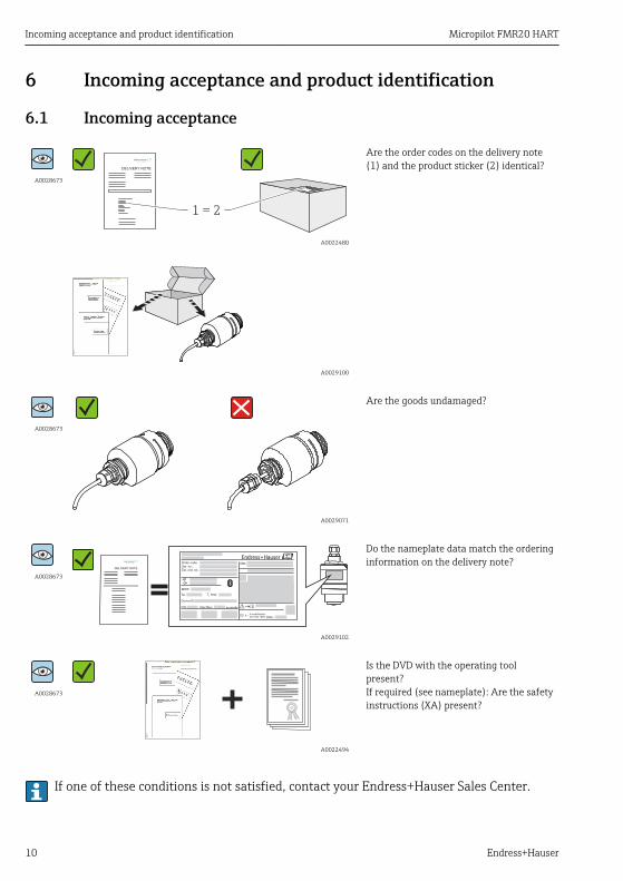
6.1 Incoming acceptance
A0028673
DELIVERY NOTE
1 = 2
A0022480
Are the order codes on the delivery note(1) and the product sticker (2) identical?
A0029100
A0028673
A0029071
Are the goods undamaged?
A0028673DELIVERY NOTE
Ext. ord. cd.:
Order code:
Ser. no.:
T max:p
DeviceID:
Date:
FW ex works
Mat.:
: Dev.Rev.:
Ta:
if modificationsee sep. label
X =
MWP:
A0029102
Do the nameplate data match the orderinginformation on the delivery note?
A0028673
A0022494
Is the DVD with the operating toolpresent?If required (see nameplate): Are the safetyinstructions (XA) present?
If one of these conditions is not satisfied, contact your Endress+Hauser Sales Center.

Micropilot FMR20 HART Incoming acceptance and product identification
Endress+Hauser 11
6.2 Product identificationThe following options are available for identification of the measuring device:• Nameplate specifications• Extended order code with breakdown of the device features on the delivery note• Enter serial numbers from nameplates in W@M Device Viewer
(www.endress.com/deviceviewer): All information about the measuring device and anoverview of the scope of the associated Technical Documentation is displayed.
• Enter the serial number from the nameplates into the Endress+Hauser Operations App, orscan the 2-D matrix code (QR code) on the nameplate with theEndress+Hauser Operations App: All information about the measuring device and anoverview of the scope of the associated Technical Documentation is displayed.

Incoming acceptance and product identification Micropilot FMR20 HART
12 Endress+Hauser
12
11
8
7
6
2
1
3
4
5
19
20
18
15 16
13
17
1424
Ext. ord. cd.:
Order code:
Ser. no.:
T max:p
DeviceID:
Date:
FW ex works
Mat.:
: Dev.Rev.:
10Ta:
if modificationsee sep. label
X =
MWP:
23
21
22
9
A0029096
2 Nameplate of Micropilot
1 Manufacturer's address2 Device name3 Order code4 Serial number (ser. no.)5 Extended order code (Ext. ord. cd.)6 Supply voltage7 Signal outputs8 Process pressure9 Permitted ambient temperature (Ta)10 Maximum process temperature11 Device ID12 Firmware version (FW)13 Device revision (Dev.Rev.)14 CE mark15 Additional information about the device version (certificates, approvals)16 C-Tick17 Materials in contact with process18 Degree of protection: e.g. IP, NEMA19 Certificate symbol20 Certificate and approval relevant data21 Document number of the Safety Instructions: e.g. XA, ZD, ZE22 Modification mark23 2-D matrix code (QR code)24 Manufacturing date: year-month
Micropilot FMR20 HART Installation
Endress+Hauser 13
7 Installation
7.1 Installation conditions
7.1.1 Installation types
B C DA
A0030605
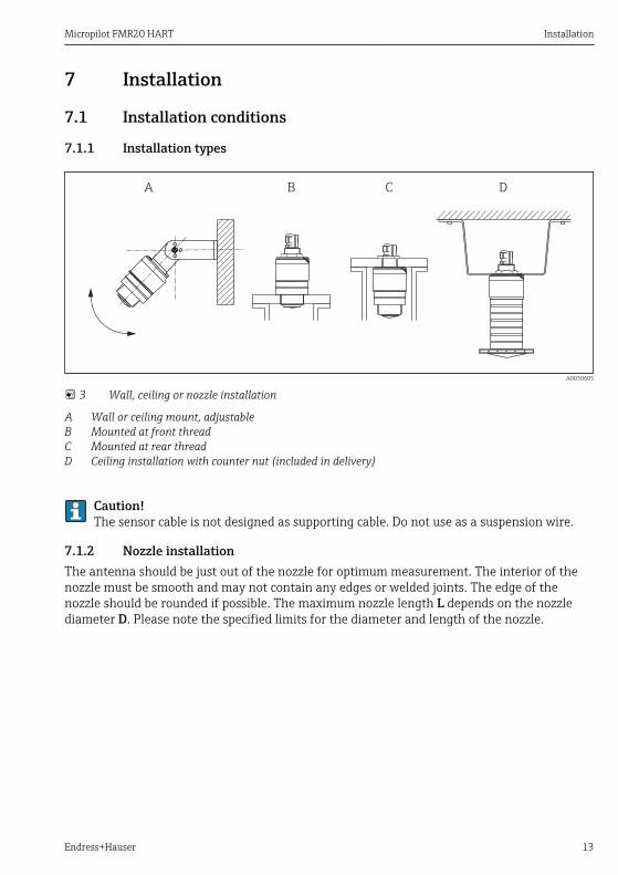
3 Wall, ceiling or nozzle installation
A Wall or ceiling mount, adjustableB Mounted at front threadC Mounted at rear threadD Ceiling installation with counter nut (included in delivery)
Caution!The sensor cable is not designed as supporting cable. Do not use as a suspension wire.
7.1.2 Nozzle installationThe antenna should be just out of the nozzle for optimum measurement. The interior of thenozzle must be smooth and may not contain any edges or welded joints. The edge of thenozzle should be rounded if possible. The maximum nozzle length L depends on the nozzlediameter D. Please note the specified limits for the diameter and length of the nozzle.

Installation Micropilot FMR20 HART
14 Endress+Hauser
BA
L
D
L
D
L
D
L
D
A0028413
4 FMR20 nozzle installation
A FMR20 80 mm (3 in) antennaB FMR20 40 mm (1.5 in) antenna
80 mm (3 in) Antenna,inside nozzle
80 mm (3 in) Antenna,outside nozzle
40 mm (1.5 in) Antenna,outside nozzle
40 mm (1.5 in) Antenna,inside nozzle
D min. 120 mm (4.72 in) min. 80 mm (3 in) min. 40 mm (1.5 in) min. 80 mm (3 in)
L max. 205 mm (8.07 in) +D x 4.5
max. D x 4.5 max. D x 1.5 max. 140 mm (5.5 in) +D x 1.5

Micropilot FMR20 HART Installation
Endress+Hauser 15
7.1.3 Orientation
1
4
1/6D
BD
2 3
D
A0028410
5 Tank installation position
• If possible install the sensor so that its lower edge projects into the vessel.• Do not install the sensor in the middle of the tank (2). We recommend leaving a distance
(1) between the sensor and the tank wall measuring 1/6 of the tank diameter.Recommended distance A wall - nozzle outer edge: ~ 1/6 of the tank diameter D. However,the device must not under any circumstances be mounted closer than 15 cm (5.91 in) to thetank wall.
• Avoid measurements through the filling curtain (3).• Avoid equipment (4) such as limit switches, temperature sensors, baffles, heating coils etc.• Multiple devices can be operated in one tank without influencing each other.• No signals are analyzed within the Blocking distance. It can therefore be used to suppress
interference signals (e.g. the effects of condensate) close to the antenna.By default an automatic Blocking distance of at least 0.1 m (0.33 ft) is preset. However itcan be manually overwritten (even 0 m (0 ft) is allowed.Automatic calculation:Blocking distance = Empty calibration - Full calibration - 0.2 m (0.656 ft).The Blocking distance parameter is recalculated according to this formula every time a newvalue is entered into the Empty calibration parameter or Full calibration parameter.If this calculation results in a value <0.1 m (0.33 ft), the blocking distance of 0.1 m (0.33 ft)is used instead.

Installation Micropilot FMR20 HART
16 Endress+Hauser
7.1.4 Alignment• Align the antenna vertically to the product surface.• Align the eyelet with the mounting eye as well as possible towards the tank wall.
90°
90°
90°
90°
90°
A0028927
6 Sensor alignment when mounting in tank
7.1.5 Beam angle
a
D
W
a_
2W = 2 x D x tan
A0029053-EN
7 Relationship between beam angle α, distance D and beamwidth diameter W

Micropilot FMR20 HART Installation
Endress+Hauser 17
The beam angle is defined as the angle α at which the power density of the radar wavesreaches half the value of the maximum power density (3dB width). Microwaves are alsoemitted outside the signal beam and can be reflected off interfering installations.Beam diameter W as a function of beam angle α and measuring distance D.
FMR20
Antenna size 40 mm (1.5 in) 80 mm (3 in)
Beam angle α 30° 12°
Distance (D) Beamwidth diameter W
3 m (9.8 ft) 1.61 m (5.28 ft) 0.63 m (2.1 ft)
5 m (16.4 ft) 2.68 m (8.79 ft) 1.05 m (3.45 ft)
10 m (33 ft) 5.36 m (17.59 ft) 2.1 m (6.9 ft)
15 m (49 ft) 3.15 m (10.34 ft)
20 m (66 ft) 4.2 m (13.79 ft)
7.1.6 Measurement in plastic vesselsIf the outer wall of the vessel is made of a non-conductive material (e.g. GFR) microwaves canalso be reflected off interfering installations outside of the vessel (e.g. metallic pipes (1),ladders (2), grates (3), ...). Therefore there should be no such interfering installations in thesignal beam. For more information, please contact Endress+Hauser.

Installation Micropilot FMR20 HART
18 Endress+Hauser
2
31
A0029540
8 Measurement in a plastic vessel
7.1.7 Weather protection coverFor outdoor use, the use of a weather protection cover(1) is recommended

Micropilot FMR20 HART Installation
Endress+Hauser 19
1
A0031277
9 Weather protection cover, e.g with 40 mm (1.5") antenna
The weather protection cover can be ordered with the device (product structure,feature 620 "Accessory enclosed", option R1 "weather protection cover").Alternatively it can be ordered separately as an accessory; order number 52025686.The sensor is not completely covered in the case of the 40 mm (1.5 in) antenna or the80 mm (3 in) antenna.
7.1.8 Free-field measurement with flooding protection tubeThe flooding protection tube guarantees a definitive analysis of the maximum level even inthe event that the sensor is completely flooded.In free-field installations and / or in applications where there is a risk of flooding, it isrecommended to use a flooding protection tube

Installation Micropilot FMR20 HART
20 Endress+Hauser
13
4
1
2
3
4
2
A0031093
10 Function of flooding protection tube
1 Air pocket2 O-ring (EPDM) seal3 Blocking distance4 Max. Level
Flooding protection tube 40 mm (1.5 in) antenna, metallized PBT-PC:For use with devices in product structure, feature 100 "Process connection front",option WFE "Thread ISO228 G1-1/2".The flooding protection tube can be ordered with the device. Product structure,feature 620 "Accessory enclosed", option R7 "Flooding protection tube, metallized PBT-PCsuitable for 40 mm (1.5 in) antenna with G1-1/2 process connection on front".Alternatively available as an accessory; order number 71325090.
Flooding protection tube 80 mm (3 in) antenna, metallized PBT-PC:For use with devices in product structure, feature 100 "Process connection front",option XR0 "Mounting customer side w/o flange".The flooding protection tube can be ordered with the device. Product structure,feature 620 "Accessory enclosed", option R8 "Flooding protection tube, metallized PBT-PCsuitable for 80 mm (3 in) antenna.Alternatively available as an accessory; order number 71327051.

Micropilot FMR20 HART Installation
Endress+Hauser 21
The tube is screwed directly onto the sensor and seals off the system by means of an O-ring(2) making it air-tight. In the event of flooding, the air pocket (1) that develops in the tubeensures a definitive detection of the maximum level (4) directly at the end of the tube. Due tothe fact that the Blocking distance (3) is inside the tube, multiple echoes are not analyzed.
Configuring the blocking distance when using the flooding protection tube‣ Navigate to: Main menu → Setup → Advanced setup → Blocking distance
Enter 100 mm (4 in).
7.1.9 Installation with mounting bracket, adjustable
A0030606
11 Installation with mounting bracket, adjustable
• Wall or ceiling installation is possible.• Using the mounting bracket, position the antenna so that it is perpendicular to the product
surface.
NOTICEThere is no conductive connection between the mounting bracket and transmitterhousing.Risk of electrostatic charge.‣ Integrate the mounting bracket in the local potential equalization system.
The mounting bracket can be ordered with the device (product structure, feature 620"Accessory enclosed", option R3 "Mounting bracket adjustable, 316L").Alternatively, it is available as an accessory, order number 71325079.

Installation Micropilot FMR20 HART
22 Endress+Hauser
7.1.10 Cantilever installation, with pivot
A B C
A0028412
12 Cantilever installation, with pivot
A Installation with cantilever and wall bracketB Installation with cantilever and mounting frameC The cantilever can be turned (e.g. in order to position the sensor over the center of the channel, for
example)
7.1.11 Post-installation check
Is the device undamaged (visual inspection)?
Is the device adequately protected from wet conditions and direct sunlight?
Is the device properly secured?

Micropilot FMR20 HART Electrical connection
Endress+Hauser 23
8 Electrical connection
8.1 Cable assignment
-+1 2
A0028954
13 Cable assignment
1 Plus, brown wire2 Minus, blue wire
8.2 Supply voltageAn external power supply is necessary.
Terminal voltage U at device Maximum load R, depending on supply voltage U0 of power supplyunit
10.5 to 30 VDC2-wireR [ ]W
U0 [V]1010.5 21.75
20 30
0
500
A0029226

Electrical connection Micropilot FMR20 HART
24 Endress+Hauser
Potential equalizationNo special measures for potential equalization are required.In the case of a device for the hazardous area, please comply with the safety instructions inthe separate "Safety Instructions" (XA, ZD) document.
Various power supply units can be ordered from Endress+Hauser.
Battery operationThe sensor's Bluetooth® wireless technology communication can be disabled to increasethe operating life of the battery.→ 44
8.3 Connection
8.3.1 FMR20, 4 to 20 mA HART
Circuit diagram / Description
FMR20 connection with HARTcommunication, voltage source and4 to 20 mA display
2
3
Y+ +
- -I
1
mA
A0028908
14 FMR20 block diagram, HART
1 Micropilot FMR202 HART resistance3 Power supply
The HART communication resistor of 250 Ω in the signal line is always necessary in thecase of a low-impedance power supply.The voltage drop to be taken into account is:Max. 6 V with 250 Ω communication resistor

Micropilot FMR20 HART Electrical connection
Endress+Hauser 25
8.3.2 FMR20 with RIA15The RIA15 remote display can be ordered together with the device.Product structure, feature 620 "Accessory enclosed":• Option R4 "Remote display RIA15 non-hazardous area, field housing"• Option R5 "Remote display RIA15 Ex= explosion protection approval, field housing"Alternatively it can be ordered separately as an accessory, for details: TechnicalInformation TI01043K and Operating Instructions BA01170KThe RIA15 process display unit is loop-powered and does not require any external powersupply.The voltage drop to be taken into account is:• ≤1 V in the standard version with 4 to 20 mA communication• ≤1.9 V with HART communication• and an additional 2.9 V if display light is used
Circuit diagram / Description
FMR20 connection, HART communicationand RIA15 without backlight
Y
IR
s DC
1
2
3
LE
D
- +
A0019567
15 FMR20 block diagram, HART with RIA15 processdisplay unit without light
1 Micropilot FMR202 Power supply3 HART resistance
FMR20 connection, HART communicationand RIA15 with backlight
Y
IR
s DC
1
2
3
LE
D
- +
A0019568
16 FMR20 block diagram, HART with RIA15 processdisplay unit with light
1 Micropilot FMR202 Power supply3 HART resistance

Electrical connection Micropilot FMR20 HART
26 Endress+Hauser
8.3.3 FMR20, RIA15 with installed HART communication resistor moduleThe HART communication module for installation in the RIA15 can be ordered togetherwith the device.Product structure, feature 620 "Accessory enclosed":• Option R6 "HART communication resistor hazardous / non-hazardous area"• The voltage drop to be taken into account is max. 7 VAlternatively it can be ordered separately as an accessory, for details: TechnicalInformation TI01043K and Operating Instructions BA01170K
Circuit diagram / Description
FMR20 connection and RIA15 withoutbacklight
1
LE
D
- +
32
Y
IR
s DC
A0020839
17 FMR20 block diagram, RIA15 without light, HARTcommunication resistor module
1 HART communication resistor module2 Micropilot FMR203 Power supply
FMR20 connection and RIA15 with backlight
1
32
Y
IR
s DC
LE
D
- +
A0020840
18 FMR20 block diagram, RIA15 with light, HARTcommunication resistor module
1 HART communication resistor module2 Micropilot FMR203 Power supply

Micropilot FMR20 HART Electrical connection
Endress+Hauser 27
8.4 Post-connection check
Is the device or cable undamaged (visual check)?
Do the cables have adequate strain relief?
Are the cable glands mounted and firmly tightened?
Does the supply voltage match the specifications on the nameplate?
No reverse polarity, is terminal assignment correct?
Has the voltage drop across the process display unit and communication resistor been taken into account?

Operability Micropilot FMR20 HART
28 Endress+Hauser
9 Operability
9.1 Operating concept• 4 to 20 mA, HART• Menu guidance with brief explanations of the individual parameter functions in the
operating tool• Optional: SmartBlue (app) via Bluetooth® wireless technology
9.2 Via Bluetooth® wireless technology
1 2 3
A0028895
19 Possibilities for remote operation via Bluetooth® wireless technology
1 Transmitter power supply unit2 Smartphone / tablet with SmartBlue (app)3 Transmitter with Bluetooth® wireless technology

Micropilot FMR20 HART Commissioning and operation
Endress+Hauser 29
9.3 Via HART protocol
1
4
5
7 9
6 8 10 11
2 3
ESC
E+
A0028894
20 Options for remote operation via HART protocol
1 PLC (programmable logic controller)2 Transmitter power supply unit, e.g. RN221N (with communication resistor)3 Connection for Commubox FXA195 and Field Communicator 375, 4754 RIA15 loop-powered process display unit5 Field Communicator 4756 Computer with operating tool (e.g. FieldCare, DeviceCare, AMS Device Manager, SIMATIC PDM)7 Commubox FXA195 (USB)8 Field Xpert SFX350/SFX3709 VIATOR with Bluetooth® wireless technology modem10 Smartphone / tablet with SmartBlue (app)11 Transmitter with Bluetooth® wireless technology
10 Commissioning and operation
10.1 Installation and function checkMake sure that all final checks have been completed before you start up your measuring point.
10.2 Operation and settings via SmartBlue (app)SmartBlue is available as download for Android devices from the Google Play Store and for iOSdevices from the iTunes Store.If you scan the QR code, you will be brought directly to the app:

Commissioning and operation Micropilot FMR20 HART
30 Endress+Hauser
A0031189-EN
21 Download Links
System requirements• iOS devices: iPhone 4S or higher from iOS9.0; iPad2 or higher from iOS9.0; iPod Touch 5.
Generation or higher from iOS9.0• Android devices: from Android 4.4 KitKat and Bluetooth® 4.0
1. Download and install SmartBlue2. Start SmartBlue
A0029747

Micropilot FMR20 HART Commissioning and operation
Endress+Hauser 31
3. Select device from livelist. All available devices are displayed.
EH_FMRx0_0123456
A0029502
22 Livelist

Commissioning and operation Micropilot FMR20 HART
32 Endress+Hauser
4. Perform login
admin
EH_FMRx0_0123456
A0029503
23 Login
5. Enter user name -> admin6. Enter initial password -> device serial number7. Change the password after logging in for the first time

Micropilot FMR20 HART Commissioning and operation
Endress+Hauser 33
8. You can drag additional information (e.g. main menu) onto the screen by swiping acrossthe screen.
EH_FMRx0_0123456
EH_FMRx0_0123456
Micropilot FMRx0
FMRx0-1234/0
EH_FMRx0_0123456
1234
A0000123456
A0029504
24 Main menu
Envelope curves can be displayed and recordedAdditionally to the envelope curve, the following values are displayed:• D = Distance• L = Level• A = Absolute amplitude• At screenshots, the displayed section (zoom function) is saved• In video sequences, always the whole area without zoom function is savedIt is also possible to send envelope curves (video sequences) using the relevantsmartphone or tablet functions

Commissioning and operation Micropilot FMR20 HART
34 Endress+Hauser
1
2
3
4
6
5
A0000123456
0123456x x
A0029486
25 Android view
1 Record video2 Create screenshot3 Start / stop video recording4 Send video5 Navigate to mapping menu6 Move time on time axis

Micropilot FMR20 HART Commissioning and operation
Endress+Hauser 35
5
1
2
3
6
x x
Envelope Curve Map Curve Weighting Curve
4
0123456
A0000123456
A0029487
26 iOS view
1 Record video2 Create screenshot3 Send video4 Navigate to mapping menu5 Start / stop video recording6 Move time on time axis

Commissioning and operation Micropilot FMR20 HART
36 Endress+Hauser
10.3 System integration via HART protocol
10.3.1 Overview of the Device Description Files (DD)
Manufacturer ID 17 (0x11)
Device type ID 44 (0x112c)
HART specification 7.0
DD files Information and files under:• www.endress.com• www.hartcomm.org
10.3.2 Measured variables via HART protocolThe following measured values are assigned to the HART variables:
HART variable Measured value
Primary variable (PV) Level linearized (PV)
Secondary variable (SV) Distance (SV)
Tertiary variable (TV) Relative echo amplitude (TV)
Quaternary variable (QV) Temperature (QV)

Micropilot FMR20 HART Commissioning and operation
Endress+Hauser 37
10.4 Operation and settings via RIA15
1
2
3
4
5
6
7
8
A0017719
27 Display and operating elements of the process display unit
1 Symbol: operating menu disabled2 Symbol: error3 Symbol: warning4 Symbol: HART communication active5 Operating keys "-", "+", "E"6 14-segment display for unit/TAG7 Bar graph with indicators for under range and over range8 5-digit 7-segment display for measured value, digit height 17 mm (0.67 in)
The device is operated using three operating keys on the front of the housing. The devicesetup can be disabled with a 4-digit user code. If the setup is disabled, a padlock symbolappears on the display when an operating parameter is selected.
A0017716
Enter key; calling up the operating menu, confirming the option/setting parameters in theoperating menu
A0017715
Selecting and setting/changing values in the operating menu; pressing the '-' and '+' keyssimultaneously takes the user back up a menu level. The configured value is not saved.
A0017714

Commissioning and operation Micropilot FMR20 HART
38 Endress+Hauser
10.4.1 Operating functionsThe operating functions of the process display unit are divided into the following menus. Theindividual parameters and settings are described in the "Commissioning" section.
If the operating menu is disabled by means of a user code, the individual menus andparameters can be displayed but not changed. To change a parameter, the user codemust be entered. As the display unit can only display digits in the 7-segment display andnot alphanumeric characters, the procedure for number parameters is different to thatfor text parameters. If the operating position contains only numbers as parameters, theoperating position is displayed in the 14-segment display and the configured parameteris displayed in the 7-segment display. To edit, press the 'E'-button followed by the usercode. If the operating position contains text parameters, only the operating position isinitially displayed in the 14-segment display. If the 'E' button is pressed again, theconfigured parameter is displayed in the 14-segment display. To edit, press the '+' buttonfollowed by the user code.
Setup (SETUP) Basic device settings
Diagnostics (DIAG) Device information, display of error messages
Expert (EXPRT) Expert settings for device setup. The Expert menu is protected from editing by an access code(default 0000).
10.4.2 Operating modesThe process display unit can be used in two different operating modes:• 4 to 20 mA mode:
In this operating mode, the process display unit is incorporated into the 4 to 20 mA currentloop and measures the transmitted current. The variable calculated based on the currentvalue and range limits is displayed in digital form on the 5-digit LCD. In addition, theassociated unit and a bar graph can be displayed. In this mode of operation, the measuredvalue corresponds to 0 to 100 %.
• HART mode:The display unit is powered via the current loop.The FMR20 can be adjusted under the "Setup Level" menu (see operating matrix). Themeasured value displayed corresponds to the distance measured or, if linearization isenabled, to a percentage value.HART communication operates according to the master/slave principle.In the HART loop, the process display unit has the option of functioning either as a primarymaster or as a secondary master (default). When it functions as a master, the device canread process values from the measuring device and display them.In HART mode, the process display unit can show up to four device variables of amultivariable measuring device. These variables are referred to as the Primary Variable(PV), Secondary Variable (SV), Tertiary Variable (TV) and Quaternary Variable (QV). Thesevariables are placeholders for measured values that can be retrieved using HARTcommunication.

Micropilot FMR20 HART Commissioning and operation
Endress+Hauser 39
As a general rule, the sensor is a slave and transmits information only if a request hasbeen made by the master. A HART loop can have a maximum of two HART masters atany one time. With these HART masters, a distinction is made between the primarymaster (e.g. the distributed control system) and the secondary master (e.g. handheldterminal for local operation of the measuring devices). The two masters in the loop/inthe network cannot be masters of the same type, e.g. they cannot be two "secondarymasters". If a third HART master is added to the network, one of the other masters mustbe disabled; otherwise a collision occurs in the network. If the process display unit(RIA15) is operating as a "secondary master", for example, and another "secondarymaster" (e.g. a handheld device) is added to the network, the device interrupts HARTcommunication as soon as it detects the presence of another "secondary master". Thedisplay alternates between error message C970 "Multi master collision" and "- - -". Ameasured value is not displayed in this case. The device leaves the HART loop for 30seconds and then tries to re-establish HART communication once again. Once theadditional "secondary master" is removed from the network, the device continuescommunication and displays the measured values of the sensor/actor once more.
10.4.3 Operating matrixAfter power-up:
‣ Activate the key x2 The menu "Level" is available
MENU SETUP -> LEVEL
Parameters Values Description
UNIT m Select the displayed unit
FT
EMPTY Numeric value 0 to 100 m, default2 m
Empty calibration using keys -,+,E.Enter distance from process connection to min. level
FULL Numerical value 0.001 to 100 m,default 2 m
Full calibration using keys -,+,E.Enter span from max. level to min. level
DIST Measured value (distance measured)
MAP DI OK To be selected if the distance displayed matches theactual distance. The device then records a mapping.
MAN To be selected if the range of mapping is to be definedmanually in the 'Mapping end point' parameter. Acomparison between the distance displayed and theactual distance is not necessary in this case. It takesabout 20 s until the mapping is active.
DI UN To be selected if the actual distance is unknown. Nomapping is recorded.

Commissioning and operation Micropilot FMR20 HART
40 Endress+Hauser
MENU SETUP -> LEVEL
Parameters Values Description
FACT To be selected if the present mapping curve (if oneexists) is to be deleted. The device returns to the"Confirm distance" parameter and a new mapping can berecorded.
The end point of the current mapping is not indicated in the RIA 15. If a new mapping isrecorded ("DI OK" or "MAN"), the new mapping is superimposed on the existing mapping.In order to bring about a defined state, perform a factory mapping ("FACT") if required.This deletes any previous mapping.
Using the following operating matrix, a display in percent can be set. To do this, select "Mode"parameter => 4-20 and "Unit" parameter => %
MENU SETUP
Parameters Values visible at Description
MODE 4-20HART
Select the operating mode for the displayunit4-20: The circuit's 4 to 20 mA signal isdisplayed.HART: Up to four HART variables (PV, SV,TV, QV) per sensor/actuator can bedisplayed in the loop.
DECIM 0 DEC1 DEC2 DEC3 DEC4 DEC
MODE = 4-20 Number of decimal places for display
SC__4 Numerical value–19 999…99 999Default: 0.0
MODE = 4-20 5-digit value (number of decimal places asconfigured under DECIM ) for scaling themeasured valueat 4 mA Example: SC__4 = 0.0 => 0.0displayed for 4 mA measuring currentThe unit selected under UNIT is used todisplay the value.
SC_20 Zahlenwert–19 999…99 999Default: 100.0
MODE = 4-20 5-digit value (number of decimal places asconfigured under DECIM ) for scaling themeasured valueat 20 mA Example: SC__20 = 100.0 =>100.0 displayed for 20 mA measuringcurrentThe unit selected under UNIT is used todisplay the value.

Micropilot FMR20 HART Commissioning and operation
Endress+Hauser 41
MENU SETUP
Parameters Values visible at Description
UNIT %°C°FKUSER
MODE = 4-20 Use this function to select the unit fordisplaying the value. If "USER" is selected,a user-defined unit can be entered in theTEXT parameter.
TEXT Customized text, 5-digit MODE = 4-20 User-defined unit, only visible if the"USER" option has been selected underUNIT.
Any additional settings such as linearizations must be made using FieldCare, DeviceCareor SmartBlue.Additional information is available in the RIA15 Operating Instructions BA01170K.
10.5 Configuring level measurement via operating software
RBD
100%
0%
D
L
FE
A0028417
28 Configuration parameters for level measurement in liquids
R Reference point of measurementD DistanceL LevelE Empty calibration (= zero point)F Full calibration (= span)BD Blocking distance
1. Navigate to: Setup → Device tag Enter device tag

Commissioning and operation Micropilot FMR20 HART
42 Endress+Hauser
2. Navigate to: Setup → Distance unit Select unit of length for distance calculation
3. Navigate to: Setup → Empty calibration Specify empty distance E (distance from reference point R to minimum level)
4. Navigate to: Setup → Full calibration Specify full distance F (span: max. level - min. level)
5. Navigate to: Setup → Distance Shows the distance D that is currently measured from the reference point (lower
edge of flange / last thread of the sensor) to the level6. Navigate to: Setup → Level
Shows the level L measured7. Navigate to: Setup → Signal quality
Displays the signal quality of the analyzed level echo8. Navigate to: Setup → Confirm distance
Compare the distance displayed with the actual value to start recording aninterference echo map
9. Navigate to: Setup → Mapping end point This parameter determines the distance up to which the new mapping is to be
recorded10. Navigate to: Setup → Present mapping
Displays the distance up to which a mapping has already been recorded
10.5.1 Displaying level value as %In combination Full calibration with Empty calibration and given 4 to 20 mA output signal,the level value for 4 mA (=Empty) and the level value for 20 mA (=Full) can be determineddirectly in the unit of length used.The Full calibration can be used to calculate a standardized signal proportionate to the levele.g. 0 to 100 % level. The two basic values of 0 % and 100 % can in turn be assigned directlyto the analog output values 4 mA and 20 mA.
X Level in m Y Output signal as %
X1 0.00 m (0.00 ft) Y1 0 %
X2 Value F (=Full) Y2 100 %
Configuration using DeviceCare or FieldCare1. Navigate to: Setup → Advanced setup
Select table as the linearization type2. Call up the linearization table3. X1 = Specify level value in m / ft for 0 %

Micropilot FMR20 HART Commissioning and operation
Endress+Hauser 43
4. X2 = X1 = Specify level value in m / ft for 100 %5. Confirm table as the linearization type
Configuration using SmartBlue1. Navigate to: Main menu → Setup → Advanced setup → Linearization type
Select table as the linearization type2. Select linearization table3. X1 = Specify level value in m / ft for 0 %4. X2 = Specify level value in m / ft for 100 %5. Activate linearization table

Commissioning and operation Micropilot FMR20 HART
44 Endress+Hauser
10.6 Data access - Security
10.6.1 Software locking via access code in FieldCare / DeviceCareThe configuration data can be write-protected using an access code (software locking).
‣ Navigate to: Setup → Advanced setup → Administration → Define access code → Confirmaccess code
The entered code must be different from "0000" and the last release code.
Once the access code has been defined, write-protected devices can be switched tomaintenance mode only if the access code is entered in the Enter access code parameter. Ifthe factory setting is not changed or if 0000 is entered, the device is in maintenance modeand its configuration data are therefore not write-protected and can be changed at any time.
10.6.2 Unlocking via FieldCare / DeviceCare‣ Navigate to: Setup → Advanced setup → Enter access code
10.6.3 Software locking via access code in SmartBlueThe configuration data can be write-protected using an access code (software locking).
‣ Navigate to: Setup → Advanced setup → Administration → Administration1 → Defineaccess code → Confirm access code
The entered code must be different from "0000" and the last release code.
Once the access code has been defined, write-protected devices can be switched tomaintenance mode only if the access code is entered in the Enter access code parameter. Ifthe factory setting is not changed or if 0000 is entered, the device is in maintenance modeand its configuration data are therefore not write-protected and can be changed at any time.
10.6.4 Unlocking via SmartBlue‣ Navigate to: Setup → Advanced setup → Zugriffsrechte Bediensoftware → Enter access code
10.6.5 Bluetooth® wireless technologySignal transmission via Bluetooth® wireless technology is done by an ecryption methodtested by the Fraunhofer-Institut (Third Party).• Without the SmartBlue App, the device is not visible via Bluetooth® wireless technology• Only one point-to-point connection between one sensor and one smartphone or tablet is
established.• The Bluetooth® wireless technology interface can be deactivated in SmartBlue, FieldCare
and DeviceCare
Deactivate Bluetooth® wireless technology interface‣ Navigate to: Setup → Communication → Bluetooth configuration → Bluetooth mode
Switch off Bluetooth® wireless technology interface. "Off" position disables remoteaccess via app
Micropilot FMR20 HART Commissioning and operation
Endress+Hauser 45
Re-activate Bluetooth® wireless technology interfaceIf Bluetooth® wireless technology interface was disabled, it can be re-activated anytime viaFieldCare / DeviceCare
‣ Navigate to: Setup → Communication → Bluetooth configuration → Bluetooth mode Switch on Bluetooth® wireless technology interface. "On" position enables remote
access via app
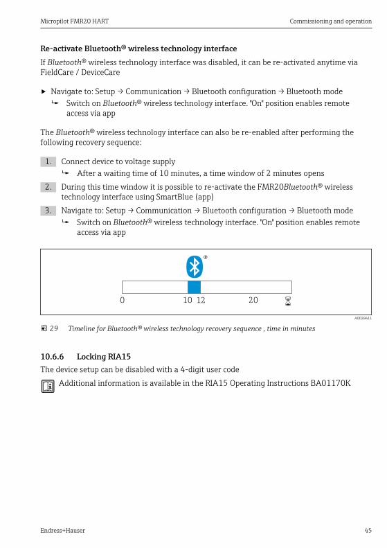
The Bluetooth® wireless technology interface can also be re-enabled after performing thefollowing recovery sequence:
1. Connect device to voltage supply After a waiting time of 10 minutes, a time window of 2 minutes opens
2. During this time window it is possible to re-activate the FMR20Bluetooth® wirelesstechnology interface using SmartBlue (app)
3. Navigate to: Setup → Communication → Bluetooth configuration → Bluetooth mode Switch on Bluetooth® wireless technology interface. "On" position enables remote
access via app
10 120 20 6
A0028411
29 Timeline for Bluetooth® wireless technology recovery sequence , time in minutes
10.6.6 Locking RIA15The device setup can be disabled with a 4-digit user code
Additional information is available in the RIA15 Operating Instructions BA01170K

Supplementary documentation Micropilot FMR20 HART
46 Endress+Hauser
11 Supplementary documentationThe following document types are available in the Download Area of the Endress+HauserInternet site: www.endress.com → Download:
11.1 Standard documentation
Device Document type Document code
FMR20 Operating Instructions BA01578F
Device Document type Document code
FMR20 Technical Information TI01267F
11.2 Supplementary documentation
Device Document type Document code
RIA15 Technical Information TI01043K
Operating Instructions BA01170K
11.3 Safety Instructions (XA)Depending on the approval, the following Safety Instructions (XA) are supplied with thedevice. They are an integral part of the Operating Instructions.
Feature 020 "Power Supply; Output" Approval Available for
A 1), P 2)
BA ATEX: II 1 G Ex ia IIC T4 Ga XA01443F
BB ATEX: II 1/2 G Ex ia IIC T4 Ga/Gb
IA IEC: Ex ia IIC T4 Ga
IB IEC: Ex ia IIC T4 Ga/Gb
CB CSA C/US IS CI.I Div.1 Gr.A-D, AEx ia / Ex ia T4 XA01445F
1) 2-Draht; 4-20 mA HART2) 2-Draht; 4-20 mA HART /Bluetooth®
The nameplate indicates the Safety Instructions (XA) that are relevant to the device.


www.addresses.endress.com