micropillar sequence designs for fundamental inertial flow transformations
TRANSCRIPT

www.rsc.org/loc
ISSN 1473-0197
Lab on a ChipMiniaturisation for chemistry, physics, biology, materials science and bioengineering
PAPERDino Di Carlo, Baskar Ganapathysubramanian et al.Micropillar sequence designs for fundamental inertial flow transformations
Volume 14 Number 21 7 November 2014 Pages 4107–4296
Lab on a Chip
Publ
ishe
d on
18
July
201
4. D
ownl
oade
d by
Mem
oria
l Uni
vers
ity o
f N
ewfo
undl
and
on 0
2/10
/201
4 03
:38:
43.
PAPER View Article OnlineView Journal | View Issue
Lab ChipThis journal is © The Royal Society of Chemistry 2014
aDepartment of Mechanical Engineering, Iowa State University, Ames, Iowa, USA.
E-mail: [email protected] of Bioengineering, University of California, Los Angeles, California, USA.
E-mail: [email protected]
† These co-first authors contributed equally to this work.‡ These co-second authors contributed equally to this work.
Cite this: Lab Chip, 2014, 14, 4197
Received 3rd June 2014,Accepted 18th July 2014
DOI: 10.1039/c4lc00653d
www.rsc.org/loc
Micropillar sequence designs for fundamentalinertial flow transformations
Daniel Stoecklein,†a Chueh-Yu Wu,†b Keegan Owsley,‡b Yu Xie,‡a Dino Di Carlo*b
and Baskar Ganapathysubramanian*a
The ability to control the shape of a flow in a passive microfluidic device enables potential applications in
chemical reaction control, particle separation, and complex material fabrication. Recent work has
demonstrated the concept of sculpting fluid streams in a microchannel using a set of pillars or other
structures that individually deform a flow in a predictable pre-computed manner. These individual pillars
are then placed in a defined sequence within the channel to yield the composition of the individual flow
deformations – and ultimately complex user-defined flow shapes. In this way, an elegant mathematical
operation can yield the final flow shape for a sequence without an experiment or additional numerical sim-
ulation. Although these approaches allow for programming complex flow shapes without understanding
the detailed fluid mechanics, the design of an arbitrary flow shape of interest remains difficult, requiring sig-
nificant design iteration. The development of intuitive basic operations (i.e. higher-level functions that con-
sist of combinations of obstacles) that act on the flow field to create a basis for more complex
transformations would be useful in systematically achieving a desired flow shape. Here, we show eight
transformations that could serve as a partial basis for more complex transformations. We initially used in-
house, freely available custom software (uFlow), which allowed us to arrive at these transformations that
include making a fluid stream concave and convex, tilting, stretching, splitting, adding a vertex, shifting, and
encapsulating another flow stream. The pillar sequences corresponding to these transformations were sub-
sequently fabricated and optically analyzed using confocal imaging – yielding close agreement with uFlow-
predicted shapes. We performed topological analysis on each transformation, characterizing potential
sequences leading to these outputs and trends associated with changing diameter and placement of the pil-
lars. We classify operations into four sets of sequence-building concatenations: stacking, recursion, mirroring,
and shaping. The developed basis should help in the design of microfluidic systems that have a phenomenal
variety of applications, such as optofluidic lensing, enhanced heat transfer, or new polymer fiber design.
1. Introduction
The ability to control the cross-sectional shape of a fluidstream allows for a variety of microfluidic applications, fromoptimizing mixing for reactions and heat transfer1 to develop-ing tunable optical components such as fluid lenses,2 to fabri-cating shaped polymer fibers.3 The most common methodsby which fluid parcels have been diverted across a channelcross section to shape a stream make use of asymmetricstructured channels (e.g. grooves, chevrons) in Stokes flow4 orcurved channels with finite inertia.1,5,6 Grooved channels havebeen widely used to mix flows,7 and more recently,
combinations of grooves have been combined to shape flows8
in a programmable manner.Fluid inertia also allows for the cross-stream motion of
fluid parcels in curving or structured channels. Inertial fluidflow (1 < Re < 100, where the Reynolds number, Re = ρUDH/μ,is the ratio of inertial to viscous forces in the flow, with fluiddensity ρ, viscosity μ, downstream velocity U, and hydraulicdiameter DH) has recently seen increased interest in themicrofluidics community, with various strategies for manipu-lating particles emerging from equilibrium inertial focusingeffects and the action of inertial lift forces on particles.6,9
Fluid streams within a channel can also be deformed by thepresence of particles,10 curvature,1 or channel structure.11
Beebe et al. employed a serpentine channel design which effi-ciently used chaotic advection for mixing fluids.5 This mostcommon approach used Dean flows, which are induced sec-ondary flows through curved channels, to deform the flowfield and increase interfacial area for mixing. Dean flow can
, 2014, 14, 4197–4204 | 4197

Lab on a ChipPaper
Publ
ishe
d on
18
July
201
4. D
ownl
oade
d by
Mem
oria
l Uni
vers
ity o
f N
ewfo
undl
and
on 0
2/10
/201
4 03
:38:
43.
View Article Online
also act in superposition with inertial lift forces to reduce thenumber of stable particle focusing positions.6 A remarkableexample of fluid flow engineering via Dean flow was the crea-tion of a tunable optofluidic lens.2 But Dean flow is limitedin its ability to precisely deform a particular region of thefluid – that is, the entire flow cross section is manipulated.Particle-induced convection and Dean flow-based schemes –
while useful for mixing – are difficult to adapt to arbitraryflow sculpting. However, recent developments in geometry-induced secondary flows under finite inertia conditions showpromise for novel strategies in microfluid engineering withlocal flow stream perturbations.11
The inertial flow around a cylindrical pillar yields second-ary flows within a channel cross section that are localized tothe pillar location. The flow deformation around a simplegeometry in this inertial regime has been only recently inves-tigated in microfluidic systems due to the general assump-tion of Stokes flow creating fore-aft symmetry in flowdeformations around an object.6 Experimental work hasmade use of flow separation and recirculation that formdownstream of obstacles, where the fore-aft symmetry isbroken in inertial flow around a geometry placed in the crosssection of the fluid stream.1,12 More recently, microscalecylinders (pillars) have been used to induce secondary flow(separate from the flow separation) and this has been used intandem with inertial focusing in order to reposition particlestreams at high throughput.13 A single cylindrical pillar at avariety of lateral positions in a microchannel has been foundto induce a set of local fundamental deformations in inertialflow around each pillar.11 One notable aspect of the inertialflow deformation past a micropillar is the saturation ofthe turning motion of the flow within a limited distancedownstream (<~4 pillar diameters), which leads to the ideaof ‘programmability’ using pre-computed advection maps foreach pillar that are sequentially combined.
With appropriate inter-pillar spacing, pillars placedsequentially in a microfluidic channel can be used to sculptthe fluid into complex new configurations with little newcomputation.11 Useful subsequences can be labelled as func-tions, which can act on fluids alone or concatenate in orderto tailor the flow as desired. These ‘pillar programs’ can openup an extensive library of associated net deformations forfuture microfluidic applications, such as using shifted fluidstreams to improve heat transfer from local hotspots, creat-ing new methods of cell sorting in biomedical diagnostic‘lab-on-a-chip’ devices, enhancing reactions at the interfacebetween fluids by increasing the surface area of streams, orchanging the cross-sectional shape of polymer precursors fornovel material design.3
The complicated phase space on offer per micropillar wasinitially described through dimensional analysis using threenon-dimensional groups: the Reynolds number, the channelaspect ratio h/w, and normalized pillar diameter D/w, whereh, w, and D are the channel height, width, and pillar diameter,respectively. A data set of 12 400 transformations with varyingpillar diameter, offset, channel height, and flow Reynolds
4198 | Lab Chip, 2014, 14, 4197–4204
number was generated through distributed HPC resourcesby Diaz-Montes et al.14 Changing the pillar position anddiameter was observed to have a tremendous effect on thefluid transformation with a rich variety of shapes, but thevast number of permutations for sequences from this largedata set made for a daunting phase space of pillar programs.Therefore, a reduced, discretized framework was created for apreliminary foray into understanding what is possible withpillar programming. In order to quickly explore the poten-tial operations allowed by this new method of microfluidengineering, we introduce a lightweight program (uFlow,www.biomicrofluidics.com/software.php) that uses a databaseof high-precision 3D simulations based on single-pillar defor-mations. We first utilize this easily extensible program todevelop intuition with the most fundamental transformations(one to three pillars per sequence), which we eventually com-bine to design more complex, hierarchically designed trans-formations. This facilitates rapid investigation of pillarprograms without requiring access to high-performance com-putational power. A set of eight fluid transformations, chosenfor potential applications in microfluidics, are initially identi-fied as target transformations. This first set of functionshelps to illustrate the impact of pillar programming, in addi-tion to signaling the potential complexity of a more completelibrary of programs. Upon obtaining these novel transforma-tions through this software exploration, we validated thedesigns by fabricating microfluidic devices and conductingconfocal imaging. This work presents specific sequences usedto create the target operations, along with some of the basicintuition, tools, and analysis that emerged from the processof finding and understanding these operations.
2. Objective
8 fundamental transformations were identified to be poten-tially useful in microfluidic applications and are illustratedin Fig. 1. Unless specified otherwise, all transformations willbe acting on a fluid region of interest 1/5 the width of thechannel and spanning the entire height (Fig. 1(b)).
• ‘Make Concave’ (Fig. 1(a-i)) and ‘Make Convex’ (Fig. 1(a-ii))give curvature to the fluid interface for potential microscaleoptofluidic applications or as a basic tool for hierarchicaldesign by collapsing or expanding the fluid at different sections.
• ‘Tilt’ (Fig. 1(a-iii)) is among the most basic transforma-tions and could be utilized for minor deformations in hierar-chical design or as a simple folding mechanism for enhancedmixing.
• ‘Stretch’ (Fig. 1(a-iv)) flattens the fluid region, and itsability to collapse the whole shape can be useful in programdesign, as many transformations will have weaker effects onthe fluid elements near the microfluid channel walls. Controlover the thickness of the fluid via stretch will aid morecomplex fiber designs.
• ‘Split’ (Fig. 1(a-v)) has applications in fiber design andcould lead to simultaneous engineering of separate streamsin the microfluid channel.
This journal is © The Royal Society of Chemistry 2014

Fig. 1 (a) Objective transformations. (b) Schematic of microchannel, showing a cross section of the fluid elements at the inlet (middle 20% beingtracked), and a sample deformation induced by a single pillar at the center of the channel. (c) Discretized simulation scheme lettered indices forlocation space 1/8w (A–H), and (d) pillar diameters shown with indices 1–4, labelled with true pillar diameter and drawn to scale.
§ www.biomicrofluidics.com/software.php.
Lab on a Chip Paper
Publ
ishe
d on
18
July
201
4. D
ownl
oade
d by
Mem
oria
l Uni
vers
ity o
f N
ewfo
undl
and
on 0
2/10
/201
4 03
:38:
43.
View Article Online
• ‘Add Vertex’ (Fig. 1(a-vi)) stands apart from most of thetransformations due to its sharp vertices at the midsectionof the fluid. Such angles could help define a more robustinterlocking structure or hint to more complex polygonaltransformations.
• ‘Shift’ (Fig. 1(a-vii)) is a very powerful manipulation ofthe fluid flow, with potential to isolate and further engineerfluid regions of interest. A program that could laterally shiftstreams will be a boon to mixing, heat transfer, solution reac-tions, and other far-reaching applications.
• ‘Encapsulate’ (Fig. 1(a-viii)) seeks to envelope a fluidstream with the primary, central stream. It can be used tocreate a polymer sheath, induce coaxial solution reactions, orfor general mixing applications.
3. Method3.1 Computational
The phase space for this initial study is limited to manipulat-ing the non-dimensional pillar diameter, D/w, and laterallocation, y/w. The position was defined by eight equallyspaced offsets in a microchannel (h/w = 0.25), while pillardiameters were restricted to D/w = 0.375, D/w = 0.5, D/w =0.625, and D/w = 0.75. The velocity field for each pillar casewas computed by solving the Navier–Stokes equations usingthe finite element method, incorporating streamline-upwind/Petrov-Galerkin (SUPG)15 and pressure-stabilizing/Petrov–Galerkin (PSPG)16 terms to stabilize the numerical solution.No-slip boundary conditions are applied on the lateral wallsand the surface of the pillar. Due to symmetry of the flowfield, the simulation is only performed on the top half of the
This journal is © The Royal Society of Chemistry 2014
channel with mirror boundary conditions of velocity compo-nents on the centerline of the channel. We assume that thefluid is incompressible and at a steady state and that thevelocity profile is fully developed at the inlet. The pressuredrop between the inlet and the outlet is fixed and is deter-mined to match the flow rate. The inlet velocity profile andpressure drop are calculated with the method used in ref. 17,where the inlet velocity profile is predicted by solving the 2Dcross-sectional flow with a guessed pressure gradient fromthe Hagen–Poisseuille law and then corrected by linearlyadjusting the pressure gradient to give the correct flow rate.For each configuration, fluid parcels were tracked throughtheir respective velocity field to produce an advection map,which describes the displacement of each parcel as it travelsdown the channel. Stream deformation is characterized bymarking those fluid parcels that belong to a stream of inter-est and looking up the motion of those particles in the advec-tion map. Advection maps are concatenated by using aparcel's deformed location to look up the displacement inthe following map and summing displacements down the pil-lar sequence. The result is a new advection map comprisingthe net effect of the entire pillar sequence.
3.2 uFlow
A lightweight utility “uFlow” that composes advection mapsin real time using the graphical processor (GPU) available onmost modern consumer computing hardware was created(and is freely available online§). The software presents a
Lab Chip, 2014, 14, 4197–4204 | 4199
Lab on a ChipPaper
Publ
ishe
d on
18
July
201
4. D
ownl
oade
d by
Mem
oria
l Uni
vers
ity o
f N
ewfo
undl
and
on 0
2/10
/201
4 03
:38:
43.
View Article Online
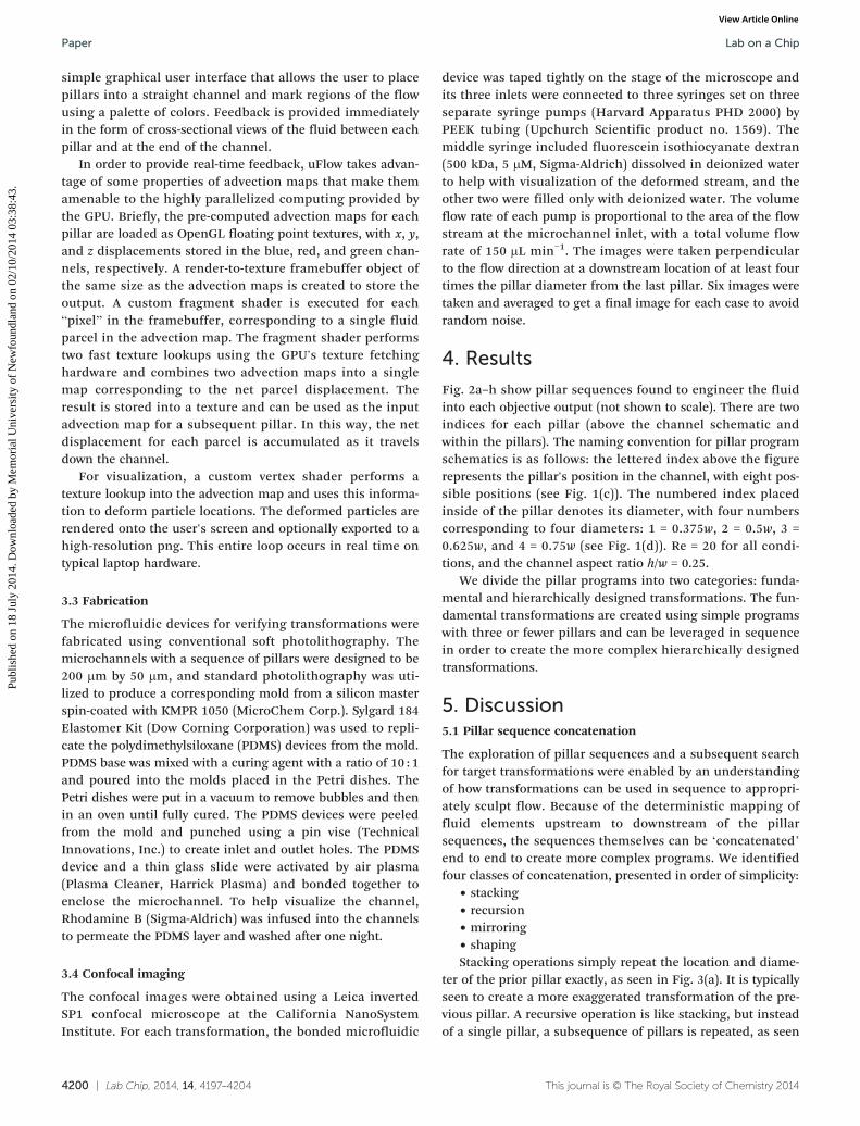
simple graphical user interface that allows the user to placepillars into a straight channel and mark regions of the flowusing a palette of colors. Feedback is provided immediatelyin the form of cross-sectional views of the fluid between eachpillar and at the end of the channel.
In order to provide real-time feedback, uFlow takes advan-tage of some properties of advection maps that make themamenable to the highly parallelized computing provided bythe GPU. Briefly, the pre-computed advection maps for eachpillar are loaded as OpenGL floating point textures, with x, y,and z displacements stored in the blue, red, and green chan-nels, respectively. A render-to-texture framebuffer object ofthe same size as the advection maps is created to store theoutput. A custom fragment shader is executed for each“pixel” in the framebuffer, corresponding to a single fluidparcel in the advection map. The fragment shader performstwo fast texture lookups using the GPU's texture fetchinghardware and combines two advection maps into a singlemap corresponding to the net parcel displacement. Theresult is stored into a texture and can be used as the inputadvection map for a subsequent pillar. In this way, the netdisplacement for each parcel is accumulated as it travelsdown the channel.
For visualization, a custom vertex shader performs atexture lookup into the advection map and uses this informa-tion to deform particle locations. The deformed particles arerendered onto the user's screen and optionally exported to ahigh-resolution png. This entire loop occurs in real time ontypical laptop hardware.
3.3 Fabrication
The microfluidic devices for verifying transformations werefabricated using conventional soft photolithography. Themicrochannels with a sequence of pillars were designed to be200 μm by 50 μm, and standard photolithography was uti-lized to produce a corresponding mold from a silicon masterspin-coated with KMPR 1050 (MicroChem Corp.). Sylgard 184Elastomer Kit (Dow Corning Corporation) was used to repli-cate the polydimethylsiloxane (PDMS) devices from the mold.PDMS base was mixed with a curing agent with a ratio of 10 : 1and poured into the molds placed in the Petri dishes. ThePetri dishes were put in a vacuum to remove bubbles and thenin an oven until fully cured. The PDMS devices were peeledfrom the mold and punched using a pin vise (TechnicalInnovations, Inc.) to create inlet and outlet holes. The PDMSdevice and a thin glass slide were activated by air plasma(Plasma Cleaner, Harrick Plasma) and bonded together toenclose the microchannel. To help visualize the channel,Rhodamine B (Sigma-Aldrich) was infused into the channelsto permeate the PDMS layer and washed after one night.
3.4 Confocal imaging
The confocal images were obtained using a Leica invertedSP1 confocal microscope at the California NanoSystemInstitute. For each transformation, the bonded microfluidic
4200 | Lab Chip, 2014, 14, 4197–4204
device was taped tightly on the stage of the microscope andits three inlets were connected to three syringes set on threeseparate syringe pumps (Harvard Apparatus PHD 2000) byPEEK tubing (Upchurch Scientific product no. 1569). Themiddle syringe included fluorescein isothiocyanate dextran(500 kDa, 5 μM, Sigma-Aldrich) dissolved in deionized waterto help with visualization of the deformed stream, and theother two were filled only with deionized water. The volumeflow rate of each pump is proportional to the area of the flowstream at the microchannel inlet, with a total volume flowrate of 150 μL min−1. The images were taken perpendicularto the flow direction at a downstream location of at least fourtimes the pillar diameter from the last pillar. Six images weretaken and averaged to get a final image for each case to avoidrandom noise.
4. Results
Fig. 2a–h show pillar sequences found to engineer the fluidinto each objective output (not shown to scale). There are twoindices for each pillar (above the channel schematic andwithin the pillars). The naming convention for pillar programschematics is as follows: the lettered index above the figurerepresents the pillar's position in the channel, with eight pos-sible positions (see Fig. 1(c)). The numbered index placedinside of the pillar denotes its diameter, with four numberscorresponding to four diameters: 1 = 0.375w, 2 = 0.5w, 3 =0.625w, and 4 = 0.75w (see Fig. 1(d)). Re = 20 for all condi-tions, and the channel aspect ratio h/w = 0.25.
We divide the pillar programs into two categories: funda-mental and hierarchically designed transformations. The fun-damental transformations are created using simple programswith three or fewer pillars and can be leveraged in sequencein order to create the more complex hierarchically designedtransformations.
5. Discussion5.1 Pillar sequence concatenation
The exploration of pillar sequences and a subsequent searchfor target transformations were enabled by an understandingof how transformations can be used in sequence to appropri-ately sculpt flow. Because of the deterministic mapping offluid elements upstream to downstream of the pillarsequences, the sequences themselves can be ‘concatenated’end to end to create more complex programs. We identifiedfour classes of concatenation, presented in order of simplicity:
• stacking• recursion• mirroring• shapingStacking operations simply repeat the location and diame-
ter of the prior pillar exactly, as seen in Fig. 3(a). It is typicallyseen to create a more exaggerated transformation of the pre-vious pillar. A recursive operation is like stacking, but insteadof a single pillar, a subsequence of pillars is repeated, as seen
This journal is © The Royal Society of Chemistry 2014

Fig. 2 Fundamental transformations Make Concave (a), Make Convex (b), Tilt (c), and Stretch (d) and hierarchical transformations Split (e),Add Vertex (f), Shift (g) and Encapsulate (h). The figures show the pillar sequence schematic on top, the numerical prediction as an output fromuFlow in the middle, and the experimental validation at the bottom.
Fig. 3 (a) Stacking demonstration with make concave. (b) Creation of add vertex via recursion (i), mirroring (ii), and shaping (iii).
Lab on a Chip Paper
Publ
ishe
d on
18
July
201
4. D
ownl
oade
d by
Mem
oria
l Uni
vers
ity o
f N
ewfo
undl
and
on 0
2/10
/201
4 03
:38:
43.
View Article Online
in the first pillar program of Fig. 3(b-i). A sequence of twopillars at positions H and B is repeated, thereby eliciting amore pronounced vertex on the left side of the midsection.Mirroring builds on recursion, except each location of therepeated subsequence is “mirrored” across the microchannel'slongitudinal centerline, as demonstrated in Fig. 3(b-ii).Mirroring can be useful for creating symmetric transforma-tions from asymmetric functions, allowing shapes to havemore complex edges. A clear example of this is the overalladd vertex transformation: mirroring is used to form vertices,while each pillar deformation is based on secondary flowsthat contain no obvious sharp angles. Finally, shaping is sim-ply an arbitrary concatenation of any subsequence to a differ-ent one, provided it is not stacking, recursive, or mirroring.An example is seen in Fig. 3(b-iii), where the known effect ofmake convex is used to create the net shape of add vertex.Shaping is a critical tool for discovering new transformationsby building on a foundation of fundamental operations, for
This journal is © The Royal Society of Chemistry 2014
the user can attempt to sculpt a fluid packet in a way definedby an operation already seen, thus further defining the hier-archy of pillar programming.
5.2 Analysis of make concave/make convex
Make concave is formed on the basis of two half-pillars at thechannel wall of diameters D/w = {0.375, 0.5, 0.625} (Fig. 4). Adiameter of 0.75w induces sharp corners in the fluid geome-try and is not effective in creating a smooth concave shape.Changing the pillar diameter changes the curvature of thefluid element, with a varying radius of curvature across themiddle 1/3 of the contour as plotted in Fig. 4(b). Note thechange in behavior with pillar diameters larger than D/w =0.375; the ‘longer’ sequences tended to force more fluid tothe edges of the channel and created a more linear contourat the convex shape's midsection, thus increasing the radiusof curvature for the majority of the shape. While it seems
Lab Chip, 2014, 14, 4197–4204 | 4201

Fig. 4 Illustrations of (a) make concave and (c) make convex per pillar type through 3 pillars and changes in mean radius of curvature vs. numberof similar pillars in sequence for (b) the make concave and (d) make convex operations.
Lab on a ChipPaper
Publ
ishe
d on
18
July
201
4. D
ownl
oade
d by
Mem
oria
l Uni
vers
ity o
f N
ewfo
undl
and
on 0
2/10
/201
4 03
:38:
43.
View Article Online
that the largest space to work while maintaining a truly con-vex shape is with D/w = 0.375, mass diffusion effects may bemagnified by difficulty in manufacturing smaller diameterpillars. Fig. 2(a) shows a poor reproduction of the numericalprediction even with the modest pillar size of D/w = 0.625,suggesting the need for incorporating a diffusion model intothe computational framework.
Make convex is a qualitative counterpart in output andprogram to make concave and primarily uses a single pillarwith diameters D/w = {0.375, 0.5, 0.625}. D/w = 0.75 results inan irregular hexagon at the output and therefore does notsatisfy the target operation requirements. Tunable convexand concave fluid shapes could provide a straight-channelalternative to Dean flow for the application of optofluidics, inaddition to novel polymer shapes, or fluid focusing tech-niques. The average change in radius of curvature per num-ber of pillars of similar diameter used is shown in Fig. 4(d).Again, it should be noted that the curvature shown is anaverage of the curvature for the middle 1/3 of the contour, asthe profile is parabolic in nature and becomes linear nearthe edge.
5.3 Analysis of stretch/split
The stretch transformation is accomplished by placing pillarson the center position of the channel. Although larger diame-ters can stretch the fluid element more rapidly – thereforerequiring fewer pillars for a desired output – it is possible toovershoot the goal of a stretching deformation and move intothe split transformation. Stretch is another example of howa transformation can be found through different pillarsequences. Fig. 5(a) shows how a 5-pillar sequence with
4202 | Lab Chip, 2014, 14, 4197–4204
pillars of D/w = 0.5 (Fig. 5(a-i)) can be effectively recreatedusing a 3-pillar sequence with pillars of D/w = 0.625 (Fig. 5(a-ii)).Attempting to create this same transformation via a 3-pillarsequence with D/w = 0.75 results in the beginning of the splittransformation (Fig. 5(a-iii)) but still meets the goal of thestretch transformation. The variety of sequences for similartransformations shows the richness of the phase space, inaddition to emphasizing the future need for numerically opti-mizing for minimal pillar sequences in order to mitigate dif-fusion effects. Fig. 5(b) illustrates the effect of increasing thepillar diameter on the change in fluid width per number ofpillars in the sequence. The split transformation (Fig. 2(e)) isan example of how pillar program recursion can produce anentirely new operation. Placing at least seven pillars of D/w =0.625 results in a separation of the fluid element into tworoughly circular elements with diminishing tails on eitherside of the channel. Adding an eighth pillar begins to distortthe separated elements until they begin to wrap back into thecenter of the channel, beginning a potential mixing scheme.
5.4 Analysis of tilt
The tilt program shown in Fig. 2(c) creates a 38° tilt, with aninternal angle of 104°. Tilt forms the basis for several hierarchi-cal operations, but there are very few ways to create tilt withthe reduced framework. The sequence uses pillar diameters ofD/w = 0.375, but moving to D/w = 0.5 removes the vertex in thetransformation. Similarly, moving outward in lateral placementalso removes the vertex. This motivates the future analysis of alarger data set with fine-grained pillar diameters and locations,which would allow for sensitivity analysis to determine thedegree of error allowed in manufacturing pillar sequences.
This journal is © The Royal Society of Chemistry 2014

Fig. 5 (a) Multiple routes to similar stretch transformations. Note that three pillars of D/w = 0.625 achieve roughly the same output as five pillarsof D/w = 0.5. Moving to a D/w = 0.75 begins the split transformation sooner, in addition to flattened ends. (b) The effect of changing diameter andincreasing numbers of central pillars on the stretched width of the central fluid element. Note that D/w = 0.75 and D = 0.625 are functionallyidentical for this effect.
Lab on a Chip Paper
Publ
ishe
d on
18
July
201
4. D
ownl
oade
d by
Mem
oria
l Uni
vers
ity o
f N
ewfo
undl
and
on 0
2/10
/201
4 03
:38:
43.
View Article Online
5.5 Analysis of add vertex
Different programs were found to arrive at the add vertextransformation, but the sequence shown in Fig. 3(b-iii) con-tains the sharpest vertices. There are two primary compo-nents to this sequence: the creation of an irregular decagonwith vertices protruding at the channel centerline and theuse of the make convex program to complete the final shape.The irregular decagon is formed by mirroring a modified38° tilt sequence that adds a vertex to one side of the fluidstructure, which results in two vertices symmetric about thechannel's y-axis, as shown in Fig. 3(b-ii). The make convexprogram, 2 pillars with D/w = 0.5, is concatenated onto theprevious eight pillars to finish the transformation. An alter-nate route is to decrease the mirrored sequence from four totwo pillars. This creates a 5-pillar program but alters the out-put edges to become more smooth and convex (see Fig. 6(b)).
This journal is © The Royal Society of Chemistry 2014
Fig. 6 (a) 10% shift (i) and 20% shift (ii). Note that the program for 20%shift is concatenated onto the 10% sequence, for a total of 22 pillars.(b) Alternative 5-pillar approach to add vertex, demonstrating the samerecursion/mirroring/shaping methods as the 10-pillar version.
5.6 Analysis of shift
The initial strategy for shifting a fluid element was to beginwith a stretch program and then force the fluid to eitherside of the channel with pillars to the left or right of thecenterline. Thin ‘tails’ are formed in the most basic shiftsequences, as seen in Fig. 6(a-i). These tails are a natural con-sequence of the secondary flow at the center of the channel,which – coupled with the no-slip boundary conditions –
results in an incomplete pinching effect at the wall/fluidinterface. To marginalize this effect, the add vertex programwas used to ‘pre-treat’ the collapsed fluid element, thereforeminimizing the fluid at the wall/fluid interface that wouldend up creating the tails. Several methods were found for theshift transformation, with lateral migration of the centralcolumn varying from 10% to 20% of the full channel width(see Fig. 6(a-ii)) and varying degrees of ‘squareness’ in thefinal output. The basic transformation as originally outlinedseeks to preserve the shape at the microchannel inlet, and theprograms shown demonstrate the best outcome to this effect.
6. Conclusions
We are able to identify a set of fundamental fluid transforma-tions using rationally chosen sequences of pillars. Thisis made possible by quickly prototyping different pillarsequences in silico and identifying those sequences that havethe desired effect on the fluid shape. The identified transfor-mations have potential applications in optofluidics, shapedfiber and particle fabrication, and mixing. The transforma-tions also provide some intuition on the types of fluid defor-mations that can be performed using pillars in a channel.
The framework utilized in this study, although appliedhere only to pillars positioned in a straight channel, can beused to analyze the flow deformation resulting from the con-catenation of arbitrary geometries, provided that the fluid is
Lab Chip, 2014, 14, 4197–4204 | 4203
Lab on a ChipPaper
Publ
ishe
d on
18
July
201
4. D
ownl
oade
d by
Mem
oria
l Uni
vers
ity o
f N
ewfo
undl
and
on 0
2/10
/201
4 03
:38:
43.
View Article Online
allowed to fully develop in between. Other geometries forconsideration include channel expansion regions, curved seg-ments, walls, asymmetric pillars, and channel bifurcations.The analysis can also be expanded to include a range ofReynolds numbers and channel aspect ratios, which wereheld fixed for this study.
Presently, the effect of diffusion on the fluid is ignored.Large numbers of pillars – and therefore longer channels –
along with more complex fluid deformations will enhancemass diffusion further downstream, resulting in a blurreddeparture from uFlow's predicted transformation. Accord-ingly, mass diffusion will limit the size of structures that canbe formed using this method, although diffusion of speciesacross streamlines may be important for many applications.The current framework can be extended to account for diffu-sion by applying a simple local diffusion model to a fluidparcel as it traverses the channel. Techniques for enablingthis analysis in real time are under investigation.
Although the present study only follows fluid parcels asthey traverse the channel, it is possible in principle to applythe same analysis to finite-sized particles suspended in thefluid flow, which may cross streamlines. Although it is moreexpensive to compute advection maps for finite-sized parti-cles, this computation is performed offline and does notaffect the speed of the analysis.
Building off this initial work, future designers of continu-ous flow fluidic systems should be able to achieve a desiredoutput behavior without significant rounds of experimentaltrial and error, paving the way for systems of increased com-plexity to address biomedical, materials fabrication, andindustrial heat and mass transport problems.
Acknowledgements
This research is supported in part by the National ScienceFoundation through XSEDE resources provided by TACC
4204 | Lab Chip, 2014, 14, 4197–4204
under grant number TG-CTS110007 and supported in part byNSF-1306866, NSF-1307550, and NSF-1149365.
References
1 A. P. Sudarsan and V. M. Ugaz, Proc. Natl. Acad. Sci. U. S. A.,
2006, 103, 7228.2 X. Mao, J. R. Waldeisen, B. K. Juluri and T. J. Huang,
Lab Chip, 2007, 7, 1303–1308.3 J. K. Nunes, C.-Y. Wu, H. Amini, K. Owsley, D. Di Carlo and
H. A. Stone, Adv. Mater., 2014, 26(22), 3712–3717.4 A. D. Stroock, S. K. W. Dertinger, A. Ajdari, I. Mezic,
H. A. Stone and G. M. Whitesides, Science, 2002, 295, 647–651.5 R. H. Liu, M. A. Stremler, K. V. Sharp, M. G. Olsen,
J. G. Santiago, R. J. Adrian, H. Aref and D. J. Beebe,J. Microelectromech. Syst., 2002, 9, 190–197.6 D. Di Carlo, Lab Chip, 2009, 9, 3038–3046.
7 P. B. Howell Jr., D. R. Mott, S. Fertig, C. R. Kaplan, J. P. Golden,E. S. Oran and F. S. Ligler, Lab Chip, 2005, 5, 524–530.8 D. A. Boyd, A. R. Shields, P. B. Howell and F. S. Ligler,
Lab Chip, 2013, 13, 3105–3110.9 G. Segré and A. Silberberg, Nature, 1961, 189, 209.
10 H. Amini, E. Sollier, W. M. Weaver and D. Di Carlo, Proc.
Natl. Acad. Sci. U. S. A., 2012, 109, 11593–11598.11 H. Amini, E. Sollier, M. Masaeli, Y. Xie, B. Ganapathysubramanian,
H. A. Stone and D. Di Carlo, Nat. Commun., 2013, 4, 1826.12 D. Chiu, Anal. Bioanal. Chem., 2007, 387, 17–20.
13 A. J. Chung, D. Pulido, J. C. Oka, H. Amini, M. Masaeli andD. Di Carlo, Lab Chip, 2013, 13, 2942–2949.14 J. Diaz-Montes, Y. Xie, I. Rodero, J. Zola, B. Ganapathysubramanian
and M. Parashar, Comput. Sci. Eng., 2014, 1–14.15 A. N. Brooks and T. J. Hughes, Comput. Methods Appl. Mech.
Eng., 1982, 32, 199–259.16 T. E. Tezduyar, S. Mittal, S. Ray and R. Shih, Comput.
Methods Appl. Mech. Eng., 1992, 95, 221–242.17 R. Jaeger, J. Ren, Y. Xie, S. Sundararajan, M. Olsen and
B. Ganapathysubramanian, Appl. Phys. Lett., 2012, 101, 184102.
This journal is © The Royal Society of Chemistry 2014