micronet 800 series controllers - storer services lonworks controller.pdf · invensys intelligent...
TRANSCRIPT

Printed in U.S.A. 9-05 © Copyright 2005 Invensys Building Systems, Inc. All rights reserved. F-26627-2
Invensys Building Systems, Inc.1354 Clifford AvenueP. O. Box 2940Loves Park, IL 61132-2940www.invensysibs.com
MicroNet 800 Series ControllersThe I/A MicroNet 800 Series Controllers are programmable, interoperable, LONWORKS® based control devices.
The MN 800 Series Controller features eight universal inputs, four analog outputs, eight digital outputs, a 5.1 volt reference, LED indication, and support for MicroNet MN-Sx Sensor Link (S-Link) sensors. Additionally, network capability is provided through the use of a FTT-10 transceiver allowing the controller to communicate to other devices as part of a LONWORKS ® Free Topology Communications network. A direct connection to a WPA-LON WorkPlace Communication adapter and a PC with WorkPlace Tech Tool software is necessary to download and modify applications.
ApplicationsDesigned for new or existing systems, the MN 800 Series Controller may be used in large I/A Series MicroNet Systems, as well as with stand alone applications. When programmed using WorkPlace Tech Tool or loaded with a previously designed application, it provides control strategies for a wide variety of mechanical equipment. Typical applications include central station air handlers, VAV air handlers, fan coil units, unit ventilators, and cooling towers.
ConnectivityThe WorkPlace Tech Tool software is used to program the controllers or to download applications. The MN 800 Series Controller offers the advantages of standalone or networked control. Using an I/A Series MicroNet sensor (MN-Sx Series), the operator can monitor controller performance and edit operational values.
Features —• Complete user creation of custom control strategies through I/A
Series WorkPlace Tech Tool software adapts the MN 800 Series Controller to virtually any HVAC control sequence or mechanical system.
• LONWORKS compatible applications are completely programmable.
• Backed-up time clock provides true stand-alone direct digital control with optimum start stop, scheduling functions, and backed-up RAM.
• Functions as part of a LONWORKS FTT-10 Free Topology communications network.
• Separate sensor bus (S-Link) supported to facilitate communications to a MicroNet wall sensor.
• Provides basic trend of up to 24 points within the application. Trend maintains last 48 analog samples or digital changes of state with time stamp. Analog sampling adjustable time rates.
LONWORKS®
MNL-800-101-CMNL-800-101

2 © Copyright 2005 Invensys Building Systems, Inc. All rights reserved. F-26627-2
Model Chart
Hardware SpecificationsMicroprocessor SAF-C161, 10 MHz clock speed, 16-bit word size.
Memory
EPROM 512 kbytes
RAM 128 kbytes
EEPROM 32 kbytes
Power Supply Input 20.4 to 30 Vac, 50/60 Hz.
Maximum Power Consumption 20 VA at 24 Vac, 50/60 Hz.
Surge Immunity ComplianceANSI C62.41 (IEEE-587, Category A & B).EN61000-4-5 Surges per EN50082-1.
Agency ListingsFCC, Part 15, Class B.UL Listed to UL-916 (File # E71385 Category PAZX).CUL, UL listed to Canadian Safety Standard (CAN/CSA C22.2)Canadian Department of Communications, Class B
European Community – EMC Directive EN55022 (Emissions, Class A)EN55014 (RF Disturbance due to switching devices as applied per EN50081-1)EN60555-2 (AC Mains Power Line Harmonics as applied per EN50081-1)
EN60555-3 (AC Mains Power Line Voltage-variation as applied per EN50081-1)EN61000-4-2 (Electrostatic Discharge as applied per EN50082-1)EN61000-4-3 (RF Immunity as applied per EN50082-1)EN61000-4-4 (Electrical Fast Transients as applied per EN50082-1)EN61000-4-5 (Surges as applied per EN50082-1)EN61000-4-6 (Radio frequency-common mode as applied per EN50082-1)EN61000-4-11 (AC Mains Voltage Dips & Interruptions as applied per EN50082-1)
Ambient LimitsOperating Temperature -40 to 140 °F (-40 to 60 °C).Shipping and Storage Temperature -40 to 160 °F (-40 to 71 °C).Humidity 5 to 95% RH, non-condensing.
Backup Clock/RAM 3 days (rechargeable) at 77 °F (25 °C).
Backed-up Time Clock Accuracy +/-150 sec/mo at 77 °F (25 °C).
Maximum Pulse Count Rate10 per second (50 msec. minimum On or Off time per pulse) to 1 per 4 minutes (IN1 only).1 per second (0.5 sec. minimum On or Off time per pulse) to 1 per 4 minutes (IN2 - IN8).
Model Mounting Type Backed-up Time Clock Dimensions (in.) H x W x D
ENCL-MZ800-WAL Wall — 10-7/8 x 8-1/2 x 4-1/4
ENCL-MZ800-PAN Panel — 10-5/8 x 8-1/2 x 4-1/8
MNL-800-101 Card Yes —
Inputs from MN-Sx I/A Series MicroNet Sensor.
Inputs Description MN-Sx Sensor
Space Temperature 32 to 122 °F (0 to 50 °C) MN-S1, MN-S1HT, MN-S2, MN-S2HT, MN-S3, MN-S3HT, MN-S4, MN-S4HT, MN-S4-FCS, MN-S4HT-FCS, MN-S5 and MN-S5HT
Space Humidity 5 to 95% RH, Non-condensing MN-S1HT, MN-S2HT, MN-S3HT, MN-S4HT, MN-S4HT-FCS, and MN-S5HT
Adjustable Setpoint 40 to 95 °F (4 to 35°C) MN-S3, MN-S3HT, MN-S4, MN-S4HT, MN-S4-FCS, MN-S4HT-FCS, MN-S5, and MN-S5HT
Override Pushbutton For standalone occupancy control or remote status monitoring of local status condition.
MN-S2, MN-S2HT, MN-S3, MN-S3HT, MN-S4, MN-S4HT, MN-S5, and MN-S5HT
Fan Operation and Speed Fan mode selection: On, Speed (Low/Medium/High), or Auto. MN-S4, MN-S4HT, MN-S4-FCS, MN-S4HT-FCS, MN-S5, and MN-S5HT
System Mode System mode selection: Heat, Cool, Off, or Auto. MN-S4, MN-S4HT, MN-S5, and MN-S5HT
Emergency Heat Emergency heat mode selection: Enable or Disable MN-S5 and MN-S5HT

F-26627-2 © Copyright 2005 Invensys Building Systems, Inc. All rights reserved. 3
Analog to Digital Conversion Resolution 12 bit.
Analog OutputsQuantity 4.Type 0-20 mA range programmable source into 80 to 550 ohm load, momentary short circuit protection.
Digital to Analog Conversion Resolution 8bit.
Digital OutputsQuantity 8.Contact Ratings 30 VA at 24 Vac, pilot duty. 120 VA at 120 Vac, pilot duty.Contact Type Form C (SPDT) isolated.Status Indication Light emitting diode.
Voltage Reference 5.1 Vdc, 20 mA maximum.
Mounting RequirementsENCL-MZ800-WAL NEMA 1 location.ENCL-MZ800-PAN Control compartment of controlled equipment.
Inputs (from I/A Series MicroNet Sensor) Space Temperature 32 to 122 °F (0 to 50 °C). Space Humidity 5 to 95% RH, non-condensing.Adjustable Setpoints 40 to 95 °F (4.4 to 35 °C). Operational Mode Heat/Cool/Auto/Off.Override Pushbutton For stand-alone occupancy control or remote status monitoring of local status condition.Emergency Heat Pushbutton Emergency heat mode selection. Enable or disable.Fan High/Med/Low.
Universal Input Quantity 8.1K Balco Input -40 to 250 °F (-40 to 121 °C) range. TSMN Series or equivalent.1K Platinum Input -40 to 240 °F (-40 to 116 °C) range. TSMN Series or equivalent.
1K ohm Copper Input -31 to 240 °F (-35 to 116 °C) range TS-5600 Series or equivalent10K Thermistor w/ 11K Shunt Resistor-40 to 250 °F (-40 to 121 °C) range. TSMN Series or equivalent.Ohms 1000 resistance (0-1500 ) 10,000 resistance (0-10,500 ).Potentiometers 1000 to 15000 resistance using 5.1 volt reference.Voltage 0 to 5 Vdc.Current 0 to 20 mA requires an external 250 shunt resistor.Digital Input Dry Contact. Detection of closed switch requires less than 300 . Detection of open switch requires more than 1.5K .
Software Capabilities• WorkPlace Tech Tool is capable of reconfiguring and editing
application configuration data to fit a wide range of control requirements.
• Interoperability achieved using LONWORKS Standard Network Variable Types (SNVTs).
CommunicationsLONWORKS Networks A LONWORKS communications network uses an FTT-10 Free Topology configuration. Controllers on a LONWORKS network can communicate with each other in a peer-to-peer fashion. A LonWorks network has a communications speed of 78k baud, using unshielded, twisted-pair cabling, with connections that are not polarity sensitive.
S-Link A Sensor Link (S-Link) communications wiring provides power and a communication interface for an MN-Sx I/A Series MicroNet sensor. The various MN-Sx sensors can provide room temperature, room humidity, setpoint adjustment, and occupancy override. This connection uses two-wire, unshielded cable and is not polarity sensitive. Maximum wire length allowed between a controller and an I/A Series MicroNet Sensor is 200 ft (61 m).
F-26627-2 Printed in U.S.A.
Invensys, I/A Series, and MicroNet are trademarks of Invensys plc and its subsidiaries and affiliates.LONMARK and LONWORKS are trademarks of Echelon Corporation.
© Copyright 2005 Invensys Building Systems, Inc. All rights reserved.No part of this document may be reproduced by any means or translated to another language without prior written consent of Invensys.All specifications are nominal and may change as design improvements are introduced. Invensys Intelligent Buildings shall not be liable for damages resulting from misapplication or misuse of its products.
LONWORKS
Network
Desktop PC or
Notebook PC with
WorkPlace Tech
Tool Software
3
1 2
5
PDA
MNL-CIM
MicroNet Controller
Interface Module
UNC Controller
Router
(if required)
6
4
4
MN 100, MN 150, or
MN 200 Controller
MN 110 or MN 130
Controller
DO
1
24
VA
C
DO
2
DO
3
24
VA
C
DO
4
Pow
er :
24V
AC
,5
0/6
0H
z,C
lass
2,
8. 5
VA
+D
O1- D
O4
load
s.
Am
bie
ntTe
mp:
-40
°Cto
+60
° C
UI :
5V
DC
Ma
x,C
lass
2.
S-L
K:
16
VD
CM
ax,
Cla
ss
2.
DO
1-D
O4
:2
4V
AC
,0.4
AM
ax
To
talL
oa
d.
DO
5:
25
0V
AC
,3
AM
ax,C
OS
f=
0. 4
.
DO
5
C5
GN
D
0V
24
VA
C
UI3
CO
M 0
V
UI2
CO
M 0
V
UI1
S-L
K
S-L
K
LO
N
LO
N
MN
L-1
1R
F2
SR
VC
RE
CV
XMI
T
J1
I /AS
erie
s
93
4G
E9
429
N2223
SR
VC
CA
UT
ION
RIS
KO
FE
LE
CT
RI C
AL
SH
OC
KO
RF
IRE
.D
ON
OT
I NT
ER
CO
NN
EC
TS
EP
AR
AT
EC
LA
SS
2C
IRC
UIT
S.
DIS
CO
NN
EC
TP
OW
ER
BE
FO
RE
SE
RV
ICIN
G.
DE
CO
NN
EC
TE
R A
VA
NT
EN
TR
ET
EN
.T
his
devic
econ
form
sw
ithP
art
15
of
the
FC
CR
ule
s.
Op
era
tion
issu
bje
ct
toth
efo
llow
ing
two
cond
ition
s:
(1)
This
de
vic
em
ay
not
cau
se
harm
fulin
terfe
rence
,and
(2)
Th
i sde
vic
em
usta
ccep
tan
yin
terf e
ren
ce
r ece
ived
,in
clu
din
g
inte
rfere
nce
tha
tm
ay
ca
use
un
de
sire
do
pe
ratio
n.
This
Cla
ss
Bd
igita
la
ppa
r atu
sm
ee
tsall
requ
irem
en
tsof
the
Ca
na
dia
nIn
terfe
rence
-Cau
sin
gE
quip
me
ntR
eg
ula
tion
s.
Tem
pe
rat u
r ei n
dic
atin
ga
nd
Re
gu
latin
gE
qu
ipm
en
t
MicroNet Sensor
(MN-S5 Shown)
MN
800
I/A Series®
MN 800
Controller
MNL-V1RVx or
MNL-V2RVx
Controller
MNL-V3RVx
or MN 50
Controller
AOAO
SW24H3
SW24H3SW24H2
SW24H2SW24H1
SW24H124H24H
24G24GGNDGND
UIUIDIDI
S-LK/COM
S-LK/COMS-LKS-LK
LONLON
LONLON
MicroNet Sensor
(MN-S3 Shown)
LONWORKS
Network
Ethernet
Desktop PC with I/A Series
Enterprise Server
3
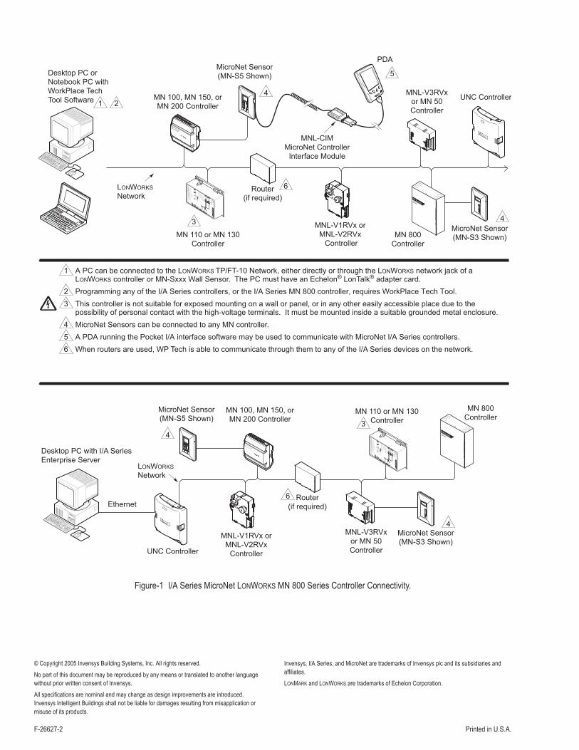
1 A PC can be connected to the LONWORKS TP/FT-10 Network, either directly or through the LONWORKS network jack of a LONWORKS controller or MN-Sxxx Wall Sensor. The PC must have an Echelon® LonTalk® adapter card.
2 Programming any of the I/A Series controllers, or the I/A Series MN 800 controller, requires WorkPlace Tech Tool.
3 This controller is not suitable for exposed mounting on a wall or panel, or in any other easily accessible place due to the possibility of personal contact with the high-voltage terminals. It must be mounted inside a suitable grounded metal enclosure.
4 MicroNet Sensors can be connected to any MN controller.
5 A PDA running the Pocket I/A interface software may be used to communicate with MicroNet I/A Series controllers.
6 When routers are used, WP Tech is able to communicate through them to any of the I/A Series devices on the network.
Router
(if required)
6
4 MN
800
I/A Series®
MN 800
Controller
4
MicroNet Sensor
(MN-S3 Shown)
MNL-V3RVx
or MN 50
Controller
AOAO
SW24H3
SW24H3SW24H2
SW24H2SW24H1
SW24H124H24H
24G24GGNDGND
UIUI
COMCOM
DIDIS-LK/COM
S-LK/COMS-LKS-LK
LONLON
LONLON
OPEN24G
OPEN24G
CLOSE24G
CLOSE24G
AOAO
MN 110 or MN 130
Controller
DO
1
24
VA
C
DO
2
DO
3
24
VA
C
DO
4
Pow
er :
24
VA
C,
50
/60H
z,C
l ass
2,
8. 5
VA
+D
O1
- DO
4lo
ad
s.
Am
bie
ntTem
p:-4
0°C
t o+
60°C
UI:
5V
DC
Max,
Cla
ss
2.
S-L
K:
16
VD
CM
ax,C
l ass
2.
DO
1-D
O4:
24V
AC
,0
.4A
Max
Tota
lLo
ad
.
DO
5:
250
VA
C,
3A
Max,
CO
Sf
=0
. 4.
DO
5
C5
GN
D
0V
24
VA
C
UI3
CO
M 0
V
UI2
CO
M 0
V
UI1
S-L
K
S-L
K
LO
N
LO
N
MN
L-1
1R
F2
SR
VC
RE
CV
XMI
T
J1
I/AS
eri e
s
934
G
E94
29
N2223
SR
VC
CA
UT
ION
RI S
KO
FE
LE
CT
RIC
AL
SH
OC
KO
RF
I RE
.D
ON
OT
INT
ER
CO
NN
EC
TS
EP
AR
AT
EC
LA
SS
2C
IRC
UIT
S.
DI S
CO
NN
EC
TP
OW
ER
BE
FO
RE
SE
RV
ICIN
G.
DE
CO
NN
EC
TE
RA
VA
NT
EN
TR
ET
EN
.T
his
devic
econfo
rms
with
Pa
rt15
of
the
FC
CR
ule
s.
Ope
ratio
nis
su
bje
ct
toth
efo
l l ow
ing
two
cond
iti ons:
(1)
This
devic
em
ay
not
cause
ha
rmfu
lin
terfe
ren
ce,a
nd
(2)
Th
i sde
vic
em
ustacce
pta
ny
inte
rf ere
nce
r eceiv
ed
,in
clu
din
g
inte
rfere
nce
that
may
cause
un
desire
do
pera
tion.
This
Cla
ss
Bd
igita
lappar a
tus
me
ets
all
requ
irem
ents
ofth
eC
ana
dia
nIn
terf e
ren
ce-C
ausin
gE
qu
ipm
ent
Reg
ul a
tions.
Te
mp
era
tur e
i ndic
atin
gan
d
Re
gu
latin
gE
qu
ipm
en
t
MicroNet Sensor
(MN-S5 Shown)MN 100, MN 150, or
MN 200 Controller
MNL-V1RVx or
MNL-V2RVx
ControllerUNC Controller
Figure-1 I/A Series MicroNet LONWORKS MN 800 Series Controller Connectivity.