microgrid structure and characteristicsjcollins/katiraei08.pdf · islanding and synchronization...
TRANSCRIPT

54 IEEE power & energy magazine may/june 20081540-7977/08/$25.00©2008 IEEE
TTHE ENVIRONMENTAL AND ECONOMICAL BENEFITS OF THE MICROGRID, ANDconsequently its acceptability and degree of proliferation in the utility power industry, are pri-marily determined by the envisioned controller capabilities and the operational features.Depending on the type and depth of penetration of distributed energy resource (DER) units, loadcharacteristics and power quality constraints, and market participation strategies, the requiredcontrol and operational strategies of a microgrid can be significantly, and even conceptually, dif-ferent than those of the conventional power systems. The main reasons are as follows:
✔ steady-state and dynamic characteristics of DER units, particularly electronically coupledunits, are different than those of the conventional large turbine-generator units
✔ a microgrid is inherently subject to a significant degree of imbalance due to the presenceof single-phase loads and/or DER units
✔ a noticeable portion of supply within a microgrid can be from “noncontrollable” sources;e.g., wind-based units
✔ short- and long-term energy storage units can play a major role in control and operationof a microgrid
✔ economics often dictate that a microgrid must readily accommodate connection and dis-connection of DER units and loads while maintaining its operation
✔ a microgrid may be required to provide prespecified power quality levels or preferentialservices to some loads
✔ in addition to electrical energy, a microgrid is often responsible for generating and sup-plying heat to all or parts of its loads.
Digital Object Identifier 10.1109/MPE.2008.918702

may/june 2008 IEEE power & energy magazine 55
This article provides an overview of the existing microgrid controls, highlights the impor-tance of power and energy management strategies, and describes potential approaches for mar-ket participation.
Microgrid Structure and CharacteristicsFigure 1 shows a microgrid schematic diagram. The microgrid encompasses a portion of anelectric power distribution system that is located downstream of the distribution substation, andit includes a variety of DER units and different types of end users of electricity and/or heat.DER units include both distributed generation (DG) and distributed storage (DS) units with dif-ferent capacities and characteristics. The electrical connection point of the microgrid to the utili-ty system, at the low-voltage bus of the substation transformer, constitutes the microgrid point ofcommon coupling (PCC). The microgrid serves a variety of customers, e.g., residential build-ings, commercial entities, and industrial parks.
The microgrid of Figure 1 normally operates in a grid-connected mode through the substationtransformer. However, it is also expected to provide sufficient generation capacity, controls, andoperational strategies to supply at least a portion of the load after being disconnected from thedistribution system at the PCC and remain operational as an autonomous (islanded) entity. Theexisting power utility practice often does not permit accidental islanding and automatic resyn-chronization of a microgrid, primarily due to the human and equipment safety concerns. Howev-er, the high amount of penetration of DER units potentially necessitates provisions for bothislanded and grid-connected modes of operations and smooth transition between the two (i.e.,
©MASTER SERIES
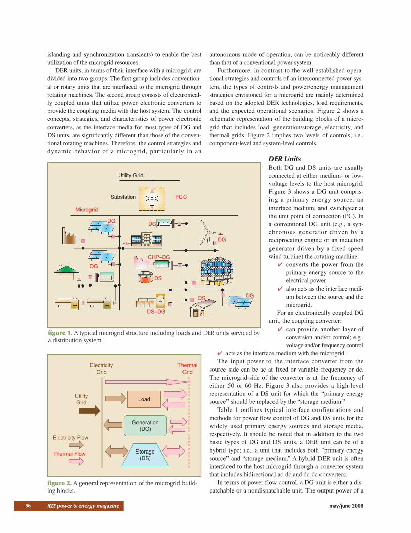
islanding and synchronization transients) to enable the bestutilization of the microgrid resources.
DER units, in terms of their interface with a microgrid, aredivided into two groups. The first group includes convention-al or rotary units that are interfaced to the microgrid throughrotating machines. The second group consists of electronical-ly coupled units that utilize power electronic converters toprovide the coupling media with the host system. The controlconcepts, strategies, and characteristics of power electronicconverters, as the interface media for most types of DG andDS units, are significantly different than those of the conven-tional rotating machines. Therefore, the control strategies anddynamic behavior of a microgrid, particularly in an
autonomous mode of operation, can be noticeably differentthan that of a conventional power system.
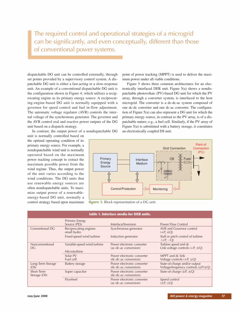
Furthermore, in contrast to the well-established opera-tional strategies and controls of an interconnected power sys-tem, the types of controls and power/energy managementstrategies envisioned for a microgrid are mainly determinedbased on the adopted DER technologies, load requirements,and the expected operational scenarios. Figure 2 shows aschematic representation of the building blocks of a micro-grid that includes load, generation/storage, electricity, andthermal grids. Figure 2 implies two levels of controls; i.e.,component-level and system-level controls.
DER UnitsBoth DG and DS units are usuallyconnected at either medium- or low-voltage levels to the host microgrid.Figure 3 shows a DG unit compris-ing a primary energy source, aninterface medium, and switchgear atthe unit point of connection (PC). Ina conventional DG unit (e.g., a syn-chronous generator driven by areciprocating engine or an inductiongenerator driven by a fixed-speedwind turbine) the rotating machine:
✔ converts the power from theprimary energy source to theelectrical power
✔ also acts as the interface medi-um between the source and themicrogrid.
For an electronically coupled DGunit, the coupling converter:
✔ can provide another layer ofconversion and/or control; e.g.,voltage and/or frequency control
✔ acts as the interface medium with the microgrid.The input power to the interface converter from the
source side can be ac at fixed or variable frequency or dc.The microgrid-side of the converter is at the frequency ofeither 50 or 60 Hz. Figure 3 also provides a high-levelrepresentation of a DS unit for which the “primary energysource” should be replaced by the “storage medium.”
Table 1 outlines typical interface configurations andmethods for power flow control of DG and DS units for thewidely used primary energy sources and storage media,respectively. It should be noted that in addition to the twobasic types of DG and DS units, a DER unit can be of ahybrid type; i.e., a unit that includes both “primary energysource” and “storage medium.” A hybrid DER unit is ofteninterfaced to the host microgrid through a converter systemthat includes bidirectional ac-dc and dc-dc converters.
In terms of power flow control, a DG unit is either a dis-patchable or a nondispatchable unit. The output power of a
56 IEEE power & energy magazine may/june 2008
Utility Grid
Substation PCC
Microgrid
DG DG
DG
CHP–DG
DS
DS+DG
DS DG
DG
figure 1. A typical microgrid structure including loads and DER units serviced bya distribution system.
ElectricityGrid
UtilityGrid
Electricity Flow
Thermal Flow
ThermalGrid
Load
Generation(DG)
Storage(DS)
figure 2. A general representation of the microgrid build-ing blocks.
may/june 2008 IEEE power & energy magazine
dispatchable DG unit can be controlled externally, throughset points provided by a supervisory control system. A dis-patchable DG unit is either a fast-acting or a slow-responseunit. An example of a conventional dispatchable DG unit isthe configuration shown in Figure 4, which utilizes a recip-rocating engine as its primary energy source. A reciprocat-ing-engine-based DG unit is normally equipped with agovernor for speed control and fuel in-flow adjustment.The automatic voltage regulator (AVR) controls the inter-nal voltage of the synchronous generator. The governor andthe AVR control real and reactive power outputs of the DGunit based on a dispatch strategy.
In contrast, the output power of a nondispatchable DGunit is normally controlled based onthe optimal operating condition of itsprimary energy source. For example, anondispatchable wind unit is normallyoperated based on the maximumpower tracking concept to extract themaximum possible power from thewind regime. Thus, the output powerof the unit varies according to thewind conditions. The DG units thatuse renewable energy sources areoften nondispatchable units. To maxi-mize output power of a renewable-energy-based DG unit, normally acontrol strategy based upon maximum
point of power tracking (MPPT) is used to deliver the maxi-mum power under all viable conditions.
Figure 5 shows three common architectures for an elec-tronically interfaced DER unit. Figure 5(a) shows a nondis-patchable photovoltaic (PV)-based DG unit for which the PVarray, through a converter system, is interfaced to the hostmicrogrid. The converter is a dc-dc-ac system composed ofone dc-dc converter and one dc-ac converter. The configura-tion of Figure 5(a) can also represent a DG unit for which theprimary energy source, in contrast to the PV array, is of a dis-patchable nature; e.g., a fuel cell. Similarly, if the PV array ofFigure 5(a) is substituted with a battery storage, it constitutesan electronically coupled DS unit.
57
Primary Energy Source (PES) Interface/Inversion Power Flow Control
Conventional DG Reciprocating engines Synchronous generator AVR and Governor controlsmall hydro (+P, ±Q)Fixed-speed wind turbine Induction generator Stall or pitch control of turbine
(+P, −Q) Nonconventional Variable-speed wind turbine Power electronic converter Turbine speed and dc DG (ac-dc-ac conversion) Link voltage controls (+P, ±Q)
MicroturbineSolar PV Power electronic converter MPPT and dc linkFuel cell (dc-dc-ac conversion) Voltage controls (+P, ±Q)
Long-Term Storage Battery storage Power electronic converter State-of-charge and/or output(DS) (dc-dc-ac conversion) Voltage/frequency controls (±P/±Q)Short-Term Super capacitor Power electronic converter State-of-charge (±P, ±Q)Storage (DS) (dc-dc-ac conversion)
Flywheel Power electronic converter Speed control(ac-dc-ac conversion) (±P, ±Q)
PrimaryEnergySource
InterfaceMedium
Grid ConnectionPoint of
Connection(PC)
CB Fuse
MonitoringControl/Protection
ic
νc
figure 3. Block representation of a DG unit.
The required control and operational strategies of a microgrid can be significantly, and even conceptually, different than those of conventional power systems.
table 1. Interface media for DER units.
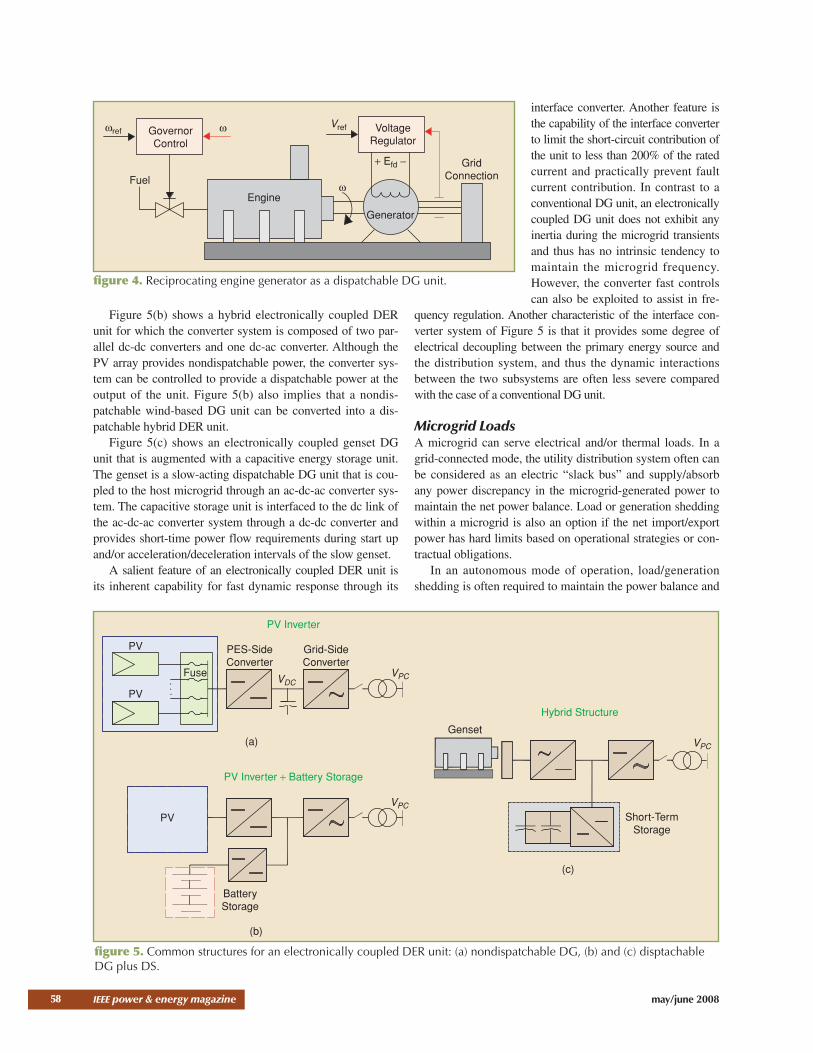
Figure 5(b) shows a hybrid electronically coupled DERunit for which the converter system is composed of two par-allel dc-dc converters and one dc-ac converter. Although thePV array provides nondispatchable power, the converter sys-tem can be controlled to provide a dispatchable power at theoutput of the unit. Figure 5(b) also implies that a nondis-patchable wind-based DG unit can be converted into a dis-patchable hybrid DER unit.
Figure 5(c) shows an electronically coupled genset DGunit that is augmented with a capacitive energy storage unit.The genset is a slow-acting dispatchable DG unit that is cou-pled to the host microgrid through an ac-dc-ac converter sys-tem. The capacitive storage unit is interfaced to the dc link ofthe ac-dc-ac converter system through a dc-dc converter andprovides short-time power flow requirements during start upand/or acceleration/deceleration intervals of the slow genset.
A salient feature of an electronically coupled DER unit isits inherent capability for fast dynamic response through its
interface converter. Another feature isthe capability of the interface converterto limit the short-circuit contribution ofthe unit to less than 200% of the ratedcurrent and practically prevent faultcurrent contribution. In contrast to aconventional DG unit, an electronicallycoupled DG unit does not exhibit anyinertia during the microgrid transientsand thus has no intrinsic tendency tomaintain the microgrid frequency.However, the converter fast controlscan also be exploited to assist in fre-
quency regulation. Another characteristic of the interface con-verter system of Figure 5 is that it provides some degree ofelectrical decoupling between the primary energy source andthe distribution system, and thus the dynamic interactionsbetween the two subsystems are often less severe comparedwith the case of a conventional DG unit.
Microgrid LoadsA microgrid can serve electrical and/or thermal loads. In agrid-connected mode, the utility distribution system often canbe considered as an electric “slack bus” and supply/absorbany power discrepancy in the microgrid-generated power tomaintain the net power balance. Load or generation sheddingwithin a microgrid is also an option if the net import/exportpower has hard limits based on operational strategies or con-tractual obligations.
In an autonomous mode of operation, load/generationshedding is often required to maintain the power balance and
58 IEEE power & energy magazine may/june 2008
GovernorControl
ωref
Fuel
Engine
Generator
GridConnection
ω
ω
Vref VoltageRegulator
+ Efd −
figure 4. Reciprocating engine generator as a dispatchable DG unit.
PV Inverter
PV
PV
PV
PV Inverter + Battery Storage
Hybrid Structure
BatteryStorage
GensetVPC
VPC
VPC
Short-TermStorage
Fuse
PES-SideConverter
Grid-SideConverter
VDC
(a)
(b)
(c)
figure 5. Common structures for an electronically coupled DER unit: (a) nondispatchable DG, (b) and (c) disptachableDG plus DS.

may/june 2008 IEEE power & energy magazine
consequently stabilize the microgrid voltage/angle. There-fore, the operating strategy must ensure that the critical loadsof the microgrid receive service priority. Furthermore, opera-tion of a microgrid should accommodate functions such ascustomer service differentiation, power quality enhancementof specific loads, and reliability improvement of prespecifiedload categories. Load control can also be exercised to opti-mize the ratings of DS units and dispatchable DG units byreducing the peak load and wide range of load variations.
In practice, part of a nonsensitiveload can be considered a controllableload and entered into a demandresponse control strategy to eitherreduce the peak load and smooth outthe load profile, or to schedule the loadserving for specific time intervals whenadditional power, for instance, fromintermittent DG units, is available. Thenoncontrollable part of a nonsensitiveload is the first candidate for load shed-ding. Load shedding and demandresponse are normally executed andsupervised through the energy manage-ment controller of the microgrid.
DER Controls Control strategies for DER units within a microgrid areselected based on the required functions and possible opera-tional scenarios. Controls of a DER unit are also determinedby the nature of its interactions with the system and otherDER units. The main control functions for a DER unit arevoltage and frequency control and/or active/reactive powercontrol. Table 2 provides a general categorization of themajor control functions of a DER unit and divides the strate-gies into the grid-following and grid-forming controls.
Each category is further divided into noninteractiveand grid-interactive strategies. The grid-followingapproach is employed when direct control of voltageand/or frequency at the PC is not required. Furthermore,if the unit output power is controlled independent of theother units or loads (nondispatchable DER unit), it consti-tutes a grid-noninteractive strategy. An example of thegrid-noninteractive strategy is the MPPT control of asolar-PV unit. A grid-interactive control strategy is basedon specifying real/reactive power set points as input com-mands. The power set points are either specified based ona power dispatch strategy or real/reactive power compen-sation of the load or the feeder.
A noninteractive, grid-forming control is an explicit methodfor voltage and frequency control of a dispatchable unit, in theabsence of the utility grid. Based on this strategy, a DER unitattempts to supply the balance of power while regulating thevoltage and stabilizing the frequency of the autonomous micro-grid. If two or more DG units share the load demand and con-currently respond to variations in the microgrid load, then aninteractive control strategy through changing voltage and fre-quency of the DER units can be applied.
Grid-Following: Power Export ControlThe grid-following power export control strategy is oftenused to control the DER output power within the voltage andfrequency limits as determined by the microgrid. If the cou-pling converter is a voltage-sourced converter (VSC), a cur-rent-controlled strategy can be used to determine thereference voltage waveforms for the pulse-width modulation(PWM) of the VSC. The reference signals are also synchro-nized to the microgrid frequency by tracking the PC voltagewaveform. The control strategy can be implemented in a syn-chronous “dq0” frame that specifies the direct (d-axis) andquadrature (q-axis) components of the converter output cur-rents corresponding to the real and reactive output powercomponents, respectively. Figure 6 shows a block diagramrepresentation of a “dq0” frame controller.
Figure 6 shows that the “d-axis” and “q-axis” currentcomponents of the VSC are extracted through an “abc” to“dq0” transformation, then compared with the correspon-ding reference signals that are specified by the externalpower or voltage control loops. The error signals areapplied to a dq current control block to determine the d-and q-component of the reference voltage signals Vd and
59
Grid-Following Controls Grid-Forming ControlsNoninteractive Control Methods Power export (with/without MPPT) Voltage and frequency controlInteractive Control Methods Power dispatch Load sharing (droop control)
Real and reactive power support
table 2. Classification of control strategies for electronically coupled DER units.
d-ReferenceController
iCa
iCb
iCc
abc
d-q
q -ReferenceController
id
iq
+−
−
+
id (ref)
iq(ref)
d -q
CurrentControl
Vd
Vq
d -q
abc
Va(ref)
Vb(ref)
Vc(ref)
PWM
Signals
Θ Θ
figure 6. “dq” current control of a VSC-interfaced DER.
Vq. Finally, through a transformation from “dq0” to “abc,”the three-phase reference signals for the PWM signal gen-erator are determined. Details of the internal and externalcontrol blocks can vary based on the control modes and thetype of primary source. Similar current control approachescan also be developed in the abc reference frame; e.g., foran unbalanced system.
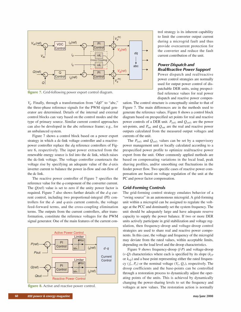
Figure 7 shows a control block based on a power exportstrategy in which a dc-link voltage controller and a reactive-power controller replace the dq reference controllers of Fig-ure 6, respectively. The input power extracted from therenewable energy source is fed into the dc link, which raisesthe dc-link voltage. The voltage controller counteracts thevoltage rise by specifying an adequate value of the d-axisinverter current to balance the power in-flow and out-flow ofthe dc link.
The reactive power controller of Figure 7 specifies thereference value for the q-component of the converter current.The Q(ref) value is set to zero if the unity power factor isrequired. Figure 7 also shows further details of the d-q cur-rent control, including two proportional-integral (PI) con-trollers for the d- and q-axis current controls, the voltagefeed-forward terms, and the cross-coupling eliminationterms. The outputs from the current controllers, after trans-formation, constitute the reference voltages for the PWMsignal generator. One of the main features of the current con-
trol strategy is its inherent capabilityto limit the converter output currentduring a microgrid fault and thusprovide overcurrent protection forthe converter and reduce the faultcurrent contribution of the unit.
Power Dispatch andReal/Reactive Power SupportPower dispatch and real/reactivepower control strategies are normallyused for output power control of dis-patchable DER units, using prespeci-fied reference values for real powerdispatch and reactive power compen-
sation. The control structure is conceptually similar to that ofFigure 7. The main differences are in the methods used togenerate the reference values. Figure 8 shows a control blockdiagram based on prespecified set points for real and reactivepower controls of a DER unit. P(ref) and Q(ref) are the powerset-points, and Pout and Qout are the real and reactive poweroutputs calculated from the measured output voltages andcurrents of the unit.
The P(ref) and Q(ref) values can be set by a supervisorypower management unit or locally calculated according to aprespecified power profile to optimize real/reactive powerexport from the unit. Other commonly applied methods arebased on compensating variations in the local load, peakshaving profiles, and/or smoothing out fluctuations in thefeeder power flow. Two specific cases of reactive power com-pensation are based on voltage regulation of the unit at thePC and power factor compensation.
Grid-Forming ControlsThe grid-forming control strategy emulates behavior of a“swing source” in an autonomous microgrid. A grid-formingunit within a microgrid can be assigned to regulate the volt-age at the PCC and dominantly set the system frequency. Theunit should be adequately large and have adequate reservecapacity to supply the power balance. If two or more DERunits actively participate in grid stabilization and voltage reg-ulation, then frequency-droop and voltage-droop controlstrategies are used to share real and reactive power compo-nents. In this case, the voltage and frequency of the microgridmay deviate from the rated values, within acceptable limits,depending on the load level and the droop characteristics.
Figure 9 shows frequency-droop (f-P) and voltage-droop(v-Q) characteristics where each is specified by its slope (kf P
or kvQ) and a base point representing either the rated frequen-cy ( fo, Po) or the nominal voltage (Vo, Qo), respectively. Thedroop coefficients and the base-points can be controlledthrough a restoration process to dynamically adjust the oper-ating points of the units. This is achieved by dynamicallychanging the power-sharing levels to set the frequency andvoltages at new values. The restoration action is normally
60 IEEE power & energy magazine may/june 2008
Vdc(ref)
Vdc
Q(ref)
Q
++−
−+VDC
Control
id
iq
iq(ref)PI
Control
PIControl
Vd(ref)
VdPC
dq
abc
Vq(ref)
+−−
−++
ωL
ωL
VqPC
QControl
id (ref)+
+
−
−
Cross-Coupling
figure 7. Grid-following power export control diagram.
P(ref)
Pout
Q(ref)
Qout
d -q
CurrentControl
Active Power ControlLimiter
Limiter
Max.
Max.
Min.
Min.
Reactive Power Control
PIControl
PIControl
+−
−+
id(ref)
iq(ref)
figure 8. Active and reactive power control.

may/june 2008 IEEE power & energy magazine
imposed very slowly and may also be exploited during resyn-chronization of an autonomous microgrid.
A block diagram of a droop control strategy is shown inFigure 10. The inputs to the controller are the locally meas-ured deviations in the frequency and the terminal voltage ofthe unit. If DER units have different capacities, the slope ofeach droop characteristic is selected proportional to the ratedcapacity of the corresponding unit to prevent overloading.
Power and Energy ManagementSound operation of a microgrid withmore than two DER units, especially inan autonomous mode, requires a powermanagement strategy (PMS) and anenergy management strategy (EMS).Fast response of the PMS/EMS is morecritical for a microgrid compared witha conventional power system. The rea-sons are:
✔ presence of multiple, small DERunits with significantly differentpower capacities and character-istics
✔ potentially no dominant sourceof energy generation during anautonomous mode; i.e., lack ofinfinite bus
✔ fast response of electronically coupled DER units thatcan adversely affect voltage/angle stability whenappropriate provisions are not in place.
Figure 11 shows information/data flow and functions of aPMS/EMS for a microgrid. The real-time management blockreceives the present and the forecasted values of load, genera-tion, and market information to impose appropriate controlson power flow, output generation, consumption level of theutility grid, dispatchable sources, and controllable loads,respectively.
The PMS/EMS assigns real andreactive power references for the DERunits to:
✔ appropriately share real/reactivepower among the DER units
✔ appropriately respond to themicrogrid disturbances and tran-sients
✔ determine the power set pointsof the DER units to balance themicrogrid power and restore thefrequency
✔ enable resynchronization of themicrogrid with the main grid, ifrequired.
In a grid-connected mode, the DERunits supply prespecified power, e.g.,to minimize power import from the
grid (peak shaving), and each unit is controlled to representeither a (real/reactive power) PQ-bus or a real-power/voltage)PV-bus. Thus, the main grid is expected to accommodate thedifference in real/reactive power supply and demand withinthe microgrid. However, in an autonomous mode, the outputpower of the units must meet the total load demand of themicrogrid. Otherwise, the microgrid must undergo a load-shedding process to match generation and demand. In addi-tion, fast and flexible real/reactive power control strategiesare required to minimize the impact of microgrid dynamics,
61
1+Δf
1.0
1−Δf
f (p.u.)
KfP
V(p.u.)
1.0
1−Δv
1+ΔvKvQ
0
(a) (b)
Po Pn P −Qm Qo0 Qn Q
figure 9. Droop characteristics for load sharing among multiple DER units: (a) f-P droop, (b) v-Q droop.
DER Controller
d -q
CurrentControl
Δf
ΔV
f-PDroop
V-QDroop
P(ref)
Pout
Q(ref)
Qout
+−
+−
ActivePowerControl
ReactivePowerControl
figure 10. Droop control strategy.
CustomerLoad
kW Electricity
kW Heat+
Present Information
Forecast
Real-TimePower/EnergyManagement
Improve/ExportPower Control
DispatchableSource Control
Utility Level
DER Level
Load LevelDemand Response
Control
ElectricityMarket
Present Information
ForecastVariableSources $
figure 11. Information flow and functions of a real-time PMS/EMS for a microgrid.

e.g., islanding transients, and damp out power and frequencyoscillations. The PMS/EMS should accommodate both short-term power balancing and long-term energy managementrequirements.
The short-term power balancing may include:✔ provisions for load-following capability, voltage regu-
lation, and frequency control based on real power shar-ing among DER units and/or load shedding to alleviatepower mismatch
✔ provisions for acceptable dynamic response, and volt-age/frequency restoration during and subsequent totransients
✔ provisions to meet power quality constraints of sensi-tive loads
✔ provision for resynchronization subsequent to the mainsystem restoration.
The long-term energy management may include:✔ provisions to maintain an appropriate level of reserve
capacity while rescheduling the operating points of dis-patchable DER units based on an optimization processto a) control the net power import/export from/to themain grid, b) minimize power loss, c) maximize power
outputs of the renewable-based units, and/or d) mini-mize the cost of energy production of fuel-based units.
✔ consideration for specific requirements/limitations ofeach DER unit, including type of unit, cost of genera-tion, time dependency of the prime source, mainte-nance intervals, and environmental impacts
✔ provisions for demand response management (load-profile control) and restoration of nonsensitive loadsthat are disconnected/shed during the microgrid tran-sients; for instance, in response to a load-sheddingrequirement subsequent to an islanding event.
Microgrid Supervisory ControlA microgrid, through its control system, must ensure all or asubset of functions (e.g., supply of electrical and/or thermalenergy, participation in the energy market, prespecified serv-ice level for critical loads, black start subsequent to a failure,provision for ancillary services, etc). The objectives areachieved through either a centralized or a decentralizedsupervisory control that includes three hierarchical levels asshown in Figure 12:
✔ distribution network operator (DNO) and market oper-ator (MO)
✔ microgrid central controller (MCC)✔ local controllers (LCs) associated with each DER unit
and/or load.The DNO is intended for an area in which more than
one microgrid exists. In addition, one (or more) MO isresponsible for the market functions of each specific area.These two entities do not belong to the microgrid but arethe delegates of the main grid. The main interface betweenthe DNO/MO and the microgrid is the MCC. The MCCassumes different roles ranging from the maximization ofthe microgrid value to coordination of LCs.
The LC controls the DER units and the controllable loadswithin a microgrid. Depending on the control approach, eachLC may have certain level of intelligence. In a centralizedoperation, each LC receives set points from the correspon-ding MCC. In a decentralized operation, each LC makesdecisions locally. Of course, in any approach, some decisionsare only locally made; e.g., an LC does not require a com-mand from the MCC for voltage control. In a centralized
approach, the LCs follow the com-mand(s) of the MCC during a grid-con-nected mode of operation and have theautonomy to:
✔ perform local optimization forpower exchange of the DERunits
✔ switch to fast load trackingmethod(s) subsequent to transi-tion to an autonomous mode.
Based on a DER bidding strategyand a high-level optimization process,the MCC provides set points to the DER
62 IEEE power & energy magazine may/june 2008
DNO MO
Microgrid A Microgrid X
Microgrid B
MCC
LC LCLC
LC
figure 12. A microgrid supervisory control architecture.
MCC(Microgrid
CentralController)
LC(Local
Controllerof Load or DER)
Prices from the Market
Loads to Be Served or Shed
Set Points for Generation
Bids of DER Units (Prices and Levels)
Demand Side Bidding (Prices and Levels)
figure 13. Information flow in a centralized controlled microgrid.
may/june 2008 IEEE power & energy magazine
units and decides whether or not to serve or control low-prior-ity loads. In a decentralized approach, the control decisionsare made by the DER LCs (e.g., power optimization to meetthe load demand, and maximizing power export to the maingrid based on market prices). Furthermore, LCs must ensuresafe and smooth operation of the loads they control.
Centralized Microgrid ControlThrough a centralized control, the MCC optimizes the micro-grid-exchanged power with the host system, thus maximizingthe local production depending on the market prices andsecurity constraints. This is achieved by issuing control setpoints to DER units and controllable loads within the micro-grid. Figure 13 illustrates the information exchange path of acentralized control strategy and indicates that a two-waycommunication between the MCC and each LC is required.The communication can be throughtelephone lines, power line carriers,or a wireless medium. The MCCtakes decisions for prespecifiedtime intervals; e.g., every 15 min-utes for the next hour or hours.Based on the market prices and unitcapacities, the DER LCs issue bidsto the MCC regarding their produc-tion levels. Similarly, the load LCsissue bids for their demands consid-ering their priorities for service.Based on the market policy, theMCC takes into account:
✔ DER and loads bids✔ market prices✔ network security constraints✔ demand and/or renewable
production forecastsand, using an optimization process, issues:
✔ production set points for DER units ✔ set points for the loads to be served or shed✔ market prices for the next optimization period to
enable LC bidding processes. Based on the MCC-issued signals, the LCs adjust genera-
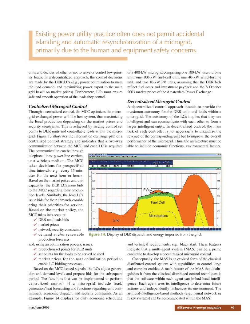
tion and demand levels and prepare bids for the subsequentperiod. The functions that can be implemented to performcentralized control of a microgrid include load/generation/heat forecasting and functions regarding unit com-mitment, economic dispatch, and security constraints. As anexample, Figure 14 displays the daily economic scheduling
of a 400-kW microgrid comprising one 100-kW microturbineunit, one 100-kW fuel-cell unit, one 40-kW wind-turbineunit, and two 10-kW PV units, assuming that the DER bidsreflect fuel costs and investment payback and the 8 October2003 market prices of the Amsterdam Power Exchange.
Decentralized Microgrid ControlA decentralized control approach intends to provide themaximum autonomy for the DER units and loads within amicrogrid. The autonomy of the LCs implies that they areintelligent and can communicate with each other to form alarger intelligent entity. In decentralized control, the maintask of each controller is not necessarily to maximize therevenue of the corresponding unit but to improve the overallperformance of the microgrid. Thus, the architecture must beable to include economic functions, environmental factors,
and technical requirements; e.g., black start. These featuresindicate that a multi-agent system (MAS) can be a primecandidate to develop a decentralized microgrid control.
Conceptually, the MAS is an evolved form of the classicaldistributed control system with capabilities to control largeand complex entities. A main feature of the MAS that distin-guishes it from the classical distributed control techniques isthat the software within each agent can imbed local intelli-gence. Each agent uses its intelligence to determine futureactions and independently influences its environment. Theartificial-intelligence-based methods (e.g., neural network orfuzzy systems) can be accommodated within the MAS.
63
50 50
PVs
Fuel Cell
MicroturbineGrid
Wind
100
350
300
250
200
150
100
kW
50
0
350
300
250
200
150
100
50
0
figure 14. Display of DER dispatch and energy imported from the grid.
Existing power utility practice often does not permit accidentalislanding and automatic resynchronization of a microgrid, primarily due to the human and equipment safety concerns.

An intelligent microgrid requires a fairly advanced com-munication system with capabilities similar to the humanspeech; e.g., the Agent Communication Language (ACL) thatprovides an environment for information and knowledgeexchange. The need for a high-level communication environ-
ment can be shown by considering the communication needsof two agents within a microgrid. For example, at a giventime one may have an instantaneous surplus of 1,500 W andthe other may need 500 W. It is neither efficient nor requiredto provide the exact values, since the situation can change
64 IEEE power & energy magazine may/june 2008
DNO MO
MicrogridMicrogrid
Microgrid B
MCC
LC LC
LCLC
ManagementLevel
Grid LevelAgent
Agent Agent Agent
AgentAgent
AgentAgent
FieldLevel
figure 15. Schematic diagram of the MAS architecture for a decentralized microgrid control.
MG Central Controller
MGCC 1 Feb 2008 08:56:28 GMTVoltage= 0.0 VFrequency=0.0 HzGrid Connected =SI Status =SI Mode = SI Production = 0.0 WSI Reactive Production = 0.0 VASB Production = 0.0 WSI Battery SOC = 0.0%
Status Controls
Market
BlackStart
StandBy
ShutDown
Power Control
Sl Production
SB Production
−600
0.0
0.0
Voltage Control
Frequency Control
Reactive Control
Power Control
Black Control
Monitor
Messages
Offer for production: from PV Unit price 14.0 Offer for production: from Main Grid price 10.0 Found New Load: (agent-identifier : name House #2@Apηζ-PC:1099/JADE :ad Found New Load: (agent-identifier : name House #1@Apηζ-PC:1099/JADE :adInit Parameters send toHouse#2Init Parameters send toHouse#1Main CREATED NEW AGENT: PowerSystem from microgridload.PowerSystemMain CREATED NEW AGENT: TrackingUnit from microgridload.TrackingUnitMain CREATED NEW AGENT: House#2 from microgridload.LoadsUnitMain CREATED NEW AGENT: House#1 from microgridload.LoadsUnit
figure 16. The main frame of the MCC agent controlling a microgrid.
may/june 2008 IEEE power & energy magazine
within a short time. The ACL provides the environment toexchange messages of the form “I have currently some wattsand do not expect to use them in the next 30 minutes” or “Ineed a few extra watts in the next 30 minutes.”
The agents not only exchange simple values and on-offsignals but also knowledge, commands, beliefs, and proce-dures to be followed through the ACL. For example, theagent that controls a load can participate in the local micro-grid market by sending a request message to all DER agentsstating the amount of required energy. Furthermore, theobject-oriented nature of the ontology and data abstractionenables each agent to handle only the necessary or allowableinformation and knowledge.
Figure 15 shows a decentralized microgrid controlstructure. The higher level corresponds to a medium-volt-age network and its agent is responsible for communica-tion between the microgrid and the DNO and/or MO andthe message exchange regarding the energy market. Themedium level is the management level in which the agentscoordinate:
✔ controllers of DER/load units✔ market participation✔ possible collaborations with the adjacent microgrids. The market operation assumes that one agent is charged
for negotiations with the MO; however, the bids and theoffers result from negotiations among the local agents. Thelower level, which is also called the field level, comprises themain elements of the MAS that correspond to the LCs. Oper-ation of an LC requires an external part and an inner part. Theexternal part provides interface with the microgrid, and it iscommon for all LCs to exchange set points, bids, and com-mands. The inner part is specific to each LC and responsiblefor translating orders and/or set points and applying them tothe corresponding unit.
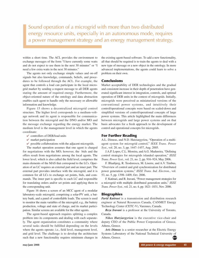
Figure 16 shows a screen of an MCC agent of a modularlaboratory-scale microgrid, comprising a solar-PV unit, a bat-tery bank, and a panel of controllable loads. The screen is usedto monitor the main variables of the microgrid; e.g., the batteryproduction, voltage and state of charge, and its market partici-pation. Similar screens are available for the other agents.
The agent-based approach requires splitting a complexproblem into its components and dealing with each separate-ly. The agent organization constitutes a community whereseveral tasks should be fulfilled depending on the levelswhere the agents operate; i.e., field level, management level,and grid level. The challenge is to develop the architecturesuch that a new functionality requires minimum changes in
the existing agent-based software. To add a new functionality,all that should be required is to train the agents to deal with anew type of message or a new object in the ontology. In moreadvanced implementations, the agents could learn to solve aproblem on their own.
ConclusionsMarket acceptability of DER technologies and the gradualand consistent increase in their depth of penetration have gen-erated significant interest in integration, controls, and optimaloperation of DER units in the context of microgrids. Initially,microgrids were perceived as miniaturized versions of theconventional power systems, and intuitively theircontrol/operational concepts were based on scaled-down andsimplified versions of control/operational concepts of largepower systems. This article highlighted the main differencesbetween microgrids and large power systems and on thatbasis advocates for a fresh approach to the development ofcontrol and operational concepts for microgrids.
For Further ReadingA.L. Dimeas, and N.D. Hatziargyriou, “Operation of a multi-agent system for microgrid control,” IEEE Trans. PowerSyst., vol. 20, no. 3, pp. 1447–1457, Aug. 2005.
J.A.P. Lopes, C.L. Moreira, and A.G. Madureira, “Definingcontrol strategies for microgrids islanded operation,” IEEETrans. Power Syst., vol. 21, no. 2, pp. 916–924, May 2006.
F. Blaabjerg, R. Teodorescu, M. Liserre, and A.V. Timbus,“Overview of control and grid synchronization for distributedpower generation systems,” IEEE Trans. Ind. Electron., vol.53, no. 5, pp. 1398–1409, Oct. 2006.
F. Katiraei, and R. Iravani, “Power management strategies fora microgrid with multiple distributed generation units,” IEEETrans. Power Syst., vol. 21, no. 4, pp. 1821–1831, Nov. 2006.
BiographiesFarid Katiraei is a transmission and distribution researchengineer at Natural Resources Canada, CANMET EnergyTechnology Center (CETC-V), Varennes, Canada.
Reza Iravani is a professor at the University of Toronto,Canada.
Nikos Hatziargyriou is the executive vice-chair anddeputy CEO of the Public Power Corporation of Greece,Athens, Greece.
Aris Dimeas is a senior researcher at the Electric EnergySystems Laboratory of the National Technical University ofAthens, Greece.
65
p&e
Sound operation of a microgrid with more than two distributedenergy resource units, especially in an autonomous mode, requiresa power management strategy and an energy management strategy.