microgrid development for tactical operations · microgrid development for tactical operations 7...
TRANSCRIPT

Microgrid Development For Microgrid Development For Tactical OperationsTactical Operations
7 May 20097 May 2009
Teri HallTeri HallElectrical Engineering StaffElectrical Engineering Staff
[email protected]@lmco.com

Lockheed Martin Proprietary Information 2
Current DoD Land Forces PowerCurrent DoD Land Forces Power
Hazardous Hazardous InfrastructureInfrastructure
Fuel ConvoysFuel Convoys Vehicle Power Vehicle Power
Inefficient ArchitectureInefficient Architecture
Capability Issues
War Fighters at Risk
Fuel Consumption
Non-optimum SWaPc
High O&M Costs
Graphics Courtesy of CERDECGraphics Courtesy of CERDEC

Lockheed Martin Proprietary Information 3
INTE
GR
ATI
ON
LEV
ELS
INTE
GR
ATI
ON
LEV
ELS
BENEFIT TO USERBENEFIT TO USER
COMPONENT COMPONENT ADVANCEMENTSADVANCEMENTS
DISTR / XMISSION DISTR / XMISSION ADVANCEMENTSADVANCEMENTS
CONTROLS CONTROLS ADVANCEMENTSADVANCEMENTS
FULL SYSTEMS FULL SYSTEMS DEVELOPMENTDEVELOPMENT
Power & Energy Integration LevelsPower & Energy Integration Levels
Holistic Approach Offers Greatest Optimization Holistic Approach Offers Greatest Optimization and Benefitand Benefit
Lockheed Martin Proprietary Information 4
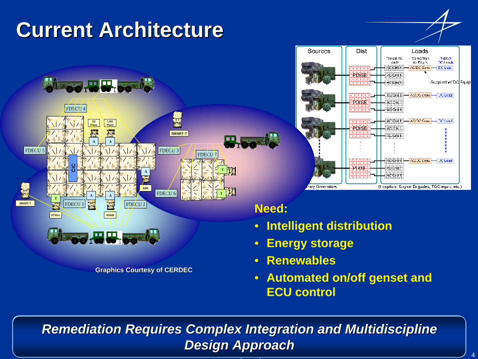
Current ArchitectureCurrent Architecture
SMART-T FDECU 1
FDECU 3FDECU 5
FDECU 2
FDECU 4
FDECU 6
FDECU 7
CIC
LOGPlans
S3Plans
DTSS-L ADAM
BSN
A A
T
TT
A
A A
SMART-T
Need:• Intelligent distribution• Energy storage• Renewables• Automated on/off genset and
ECU control
Graphics Courtesy of CERDECGraphics Courtesy of CERDEC
Remediation Requires Complex Integration and Multidiscipline Remediation Requires Complex Integration and Multidiscipline Design ApproachDesign Approach
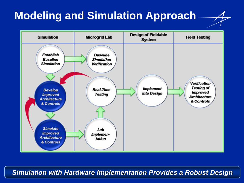
Modeling and Simulation Approach
Simulation with Hardware Implementation Provides a Robust DesignSimulation with Hardware Implementation Provides a Robust Design
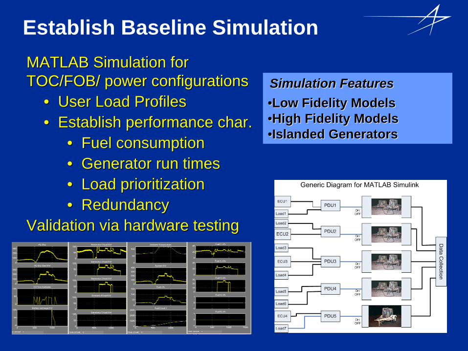
Establish Baseline Simulation
Simulation FeaturesSimulation Features••Low Fidelity ModelsLow Fidelity Models••High Fidelity ModelsHigh Fidelity Models••Islanded GeneratorsIslanded Generators
MATLAB Simulation for MATLAB Simulation for TOC/FOB/ power configurationsTOC/FOB/ power configurations
•• User Load ProfilesUser Load Profiles•• Establish performance char.Establish performance char.
•• Fuel consumptionFuel consumption•• Generator run timesGenerator run times•• Load prioritizationLoad prioritization•• RedundancyRedundancy
Validation via hardware testingValidation via hardware testing
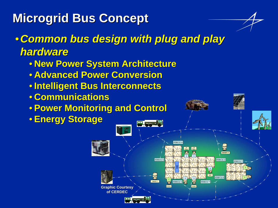
MicrogridMicrogrid Bus ConceptBus Concept•• Common bus design with plug and play Common bus design with plug and play hardware hardware
•• New Power System ArchitectureNew Power System Architecture•• Advanced Power ConversionAdvanced Power Conversion•• Intelligent Bus InterconnectsIntelligent Bus Interconnects•• CommunicationsCommunications•• Power Monitoring and ControlPower Monitoring and Control•• Energy StorageEnergy Storage
SMART-T FDECU 1
FDECU 3FDECU 5
FDECU 2
FDECU 4
FDECU 6
FDECU 7
CIC
LOGPlans
S3Plans
DTSS-L ADAM
BSN
A A
T
TT
A
A A
SMART-T
Graphic Courtesy Graphic Courtesy of CERDECof CERDEC

Simulation Features•Low & High Fidelity Models•Common Bus•Alternative Power Sources
– Wind Models– Solar Models– Fuel Cell Models
Improved Architecture SimulationSimulations showing improved fuel Simulations showing improved fuel consumption and increased efficiency.consumption and increased efficiency.
••Generators on a common busGenerators on a common bus••Energy StorageEnergy Storage••Alternative Energy SourcesAlternative Energy Sources
•• Same user load profiles as BaselineSame user load profiles as Baseline•• Establish new performance char.Establish new performance char.
••Fuel consumptionFuel consumption••Generator run timesGenerator run times••Load prioritizationLoad prioritization••RedundancyRedundancy
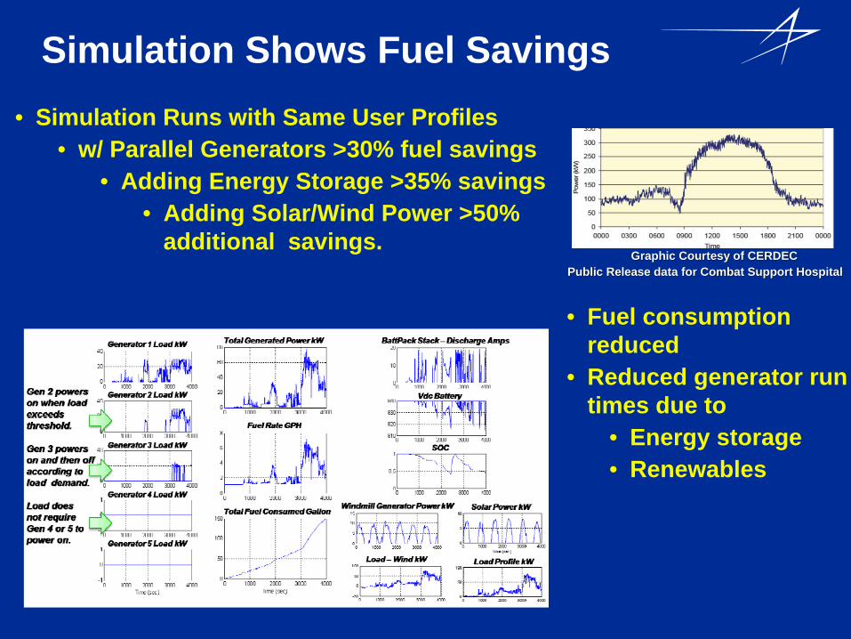
Simulation Shows Fuel Savings• Simulation Runs with Same User Profiles
• w/ Parallel Generators >30% fuel savings• Adding Energy Storage >35% savings
• Adding Solar/Wind Power >50% additional savings.
Graphic Courtesy of CERDECGraphic Courtesy of CERDEC
• Fuel consumption reduced
• Reduced generator run times due to
• Energy storage • Renewables
Public Release data for Combat Support Hospital Public Release data for Combat Support Hospital
•• Common Bus design facilitates peak load Common Bus design facilitates peak load management by employing distributed energy management by employing distributed energy sources.sources.
•• Simulations show increase in system fuel efficiency Simulations show increase in system fuel efficiency when energy storage is added to microgridswhen energy storage is added to microgrids
•• Design requires efficient power electronicsDesign requires efficient power electronics
•• Implementing solutions for:Implementing solutions for:•• Efficient power electronicsEfficient power electronics•• Automatic on/off control of energy sourcesAutomatic on/off control of energy sources•• Generator synchronizationGenerator synchronization
Energy/Power ManagementEnergy/Power Management
Simulation Results lead to Hardware ImplementationSimulation Results lead to Hardware Implementation

Hardware Implementation of Load Hardware Implementation of Load ProfilesProfiles •• Configure hardware to run military Configure hardware to run military
load profilesload profiles•• System controller (NI Chassis) System controller (NI Chassis)
manages operation of equipment.manages operation of equipment.•• Run Digital Bridge profileRun Digital Bridge profile
•• 5KW generator5KW generator•• Two synchronized 2KW Two synchronized 2KW
generatorsgenerators•• One 2KW generator with Energy One 2KW generator with Energy
Storage Storage •• Analyze and compare fuel Analyze and compare fuel
consumption with each case. consumption with each case.
Upcoming Tasks:Perform test with larger load profiles
Public Release data for Digital Bridge Mission Public Release data for Digital Bridge Mission
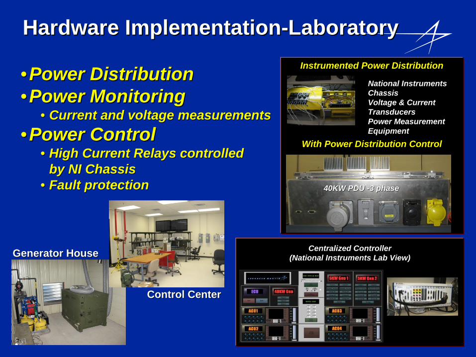
Hardware ImplementationHardware Implementation--Laboratory Laboratory
•• Power DistributionPower Distribution•• Power MonitoringPower Monitoring
•• Current and voltage measurementsCurrent and voltage measurements•• Power ControlPower Control
•• High Current Relays controlled High Current Relays controlled by NI Chassisby NI Chassis
•• Fault protectionFault protection
Instrumented Power DistributionInstrumented Power Distribution
National Instruments National Instruments Chassis Chassis Voltage & Current Voltage & Current TransducersTransducersPower Measurement Power Measurement EquipmentEquipment
With Power Distribution ControlWith Power Distribution Control
40KW PDU 40KW PDU --3 phase3 phase
Centralized ControllerCentralized Controller(National Instruments Lab View)(National Instruments Lab View)Generator HouseGenerator House
Control CenterControl Center

Lab Power Components
ECU ECU ––Air RoverAir Rover
Mil and Commercial Diesel Mil and Commercial Diesel GeneratorsGenerators
Total power >70KW.Total power >70KW.
Lab Loads Equipment Lab Loads Equipment •• Electronic DC Electronic DC •• AC Resistive AC Resistive •• Electric MotorsElectric Motors•• Environmental ControlEnvironmental Control
Energy StorageEnergy Storage•• LiLi--Ion BattPacksIon BattPacks•• Mil BatteriesMil Batteries•• Commercial Lead Commercial Lead
AcidAcid
Military TQG Diesel GeneratorsMilitary TQG Diesel Generators
Wind/ Solar Power andWind/ Solar Power andDedicated 3Dedicated 3--Phase PowerPhase Power
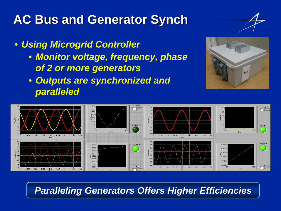
AC Bus and Generator SynchAC Bus and Generator Synch
• Using Microgrid Controller• Monitor voltage, frequency, phase
of 2 or more generators• Outputs are synchronized and
paralleled
Paralleling Generators Offers Higher EfficienciesParalleling Generators Offers Higher Efficiencies

Microgrid Lab Microgrid Lab ––Alternative Energy Alternative Energy CapabilitiesCapabilities
•• Wind Energy Wind Energy -- 1KW1KW•• Mounted on 30 ft poleMounted on 30 ft pole•• 24VDC output 24VDC output
•• Solar energy Solar energy -- 1KW 1KW •• 8 panels on building roof8 panels on building roof•• 48VDC Output 48VDC Output
•• Charge controllers maintain battery bank Charge controllers maintain battery bank at 28VDC.at 28VDC.
•• Integrating advanced energy storageIntegrating advanced energy storage•• Higher voltage buses to be evaluatedHigher voltage buses to be evaluated
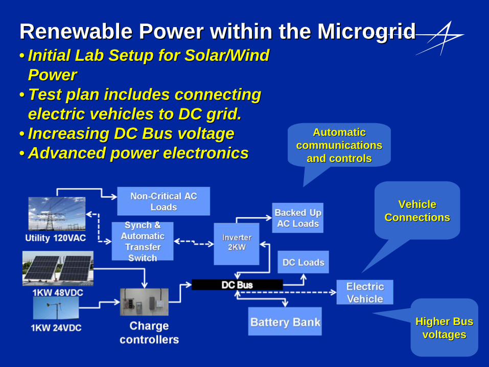
Renewable Power within the MicrogridRenewable Power within the Microgrid•• Initial Lab Setup for Solar/Wind Initial Lab Setup for Solar/Wind Power Power
•• Test plan includes connecting Test plan includes connecting electric vehicles to DC grid.electric vehicles to DC grid.
•• Increasing DC Bus voltageIncreasing DC Bus voltage•• Advanced power electronicsAdvanced power electronics
Automatic Automatic communications communications
and controlsand controls
Vehicle Vehicle ConnectionsConnections
Higher Bus Higher Bus voltagesvoltages
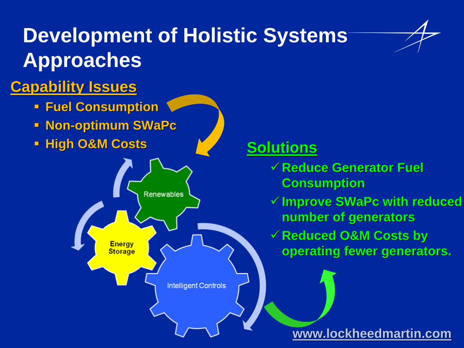
Development of Holistic Systems Approaches
Capability IssuesCapability Issues
Fuel ConsumptionFuel Consumption
NonNon--optimum SWaPcoptimum SWaPc
High O&M CostsHigh O&M Costs SolutionsSolutionsReduce Generator Fuel Reduce Generator Fuel
ConsumptionConsumption Improve SWaPc with reduced Improve SWaPc with reduced
number of generatorsnumber of generatorsReduced O&M Costs by Reduced O&M Costs by
operating fewer generators.operating fewer generators.
www.lockheedmartin.comwww.lockheedmartin.com

QUESTIONS?