microcommander 9110 operation & troubleshooting … revb 7-04... · microcommander 9110...
TRANSCRIPT

MicroCommander 9110Operation & Troubleshooting Manual
MM9110 Rev.B 7-04


PREFACE
Page Preface-1
MicroCommander 9110 Series
This manual is for the above Processors.
Throughout this manual special attention should be paid to the following:
ATTENTION
It is important to keep this Manual in a safe place for future reference. The man-ual contains answers to questions that may arise during operation or installation
of the ZF Mathers Control System and its options.
For the purpose of this manual, the drawings illustrate pluggable systems with two Remote Stations. The Processors described within, may in fact be installed with anywhere from one to five Remote Stations.
ZF Mathers ENGINE CLUTCHOPTIONAL TROLL
Processor Part No. Servo Electronic Servo Solenoid 9001 Actuator
9110 Servo 2 Servo 1 Servo 3
Table Preface-1: MicroCommander Processor List
NOTE: CONTAINS HELPFUL INFORMATION.
CAUTION: Damage to the equipment may occur if these messages are not followed.
WARNING: PERSONAL INJURY MAY RESULT IF THESE MESSAGES ARE NOT FOLLOWED.
WARNING: PERSONAL INJURY COULD OCCUR IF THE FOLLOWING STEPS ARE NOT FOLLOWED
EXACTLY.
CAUTION: On Control Systems utilizing more than one Processor, ZF Mathers highly recommends that ALL UNITS be upgraded to the most current Processor.
CAUTION: Electro-static discharge can damage this equipment. Personnel working on this equipment must be grounded to the chassis with the Anti-static Wrist Strap provided.
CAUTION: Disconnect the Power Harness from the Power Pigtail whenever welding is being done on the vessel. Failure to do so can cause permanent damage.
CAUTION This equipment is designed to work with other ZF Mathers designed equip-ment. DO NOT operate this equipment with any other manufacturers equipment unless approved so in writing by ZF Mathers Engineering Department.
CAUTION: • On MicroCommander systems utilizing more than one 585, 585CE, or 9110 Model Processors, ZF Mathers highly recommends that ALL UNITS be upgraded to the latest Model 9110 Processor.
• If you are planning to use the High/ Low Idle feature or Clutch Oil Pres-sure Interlock, Synchronization or Trolling options, DO NOT attempt to operate a 585 or 585CE Processor with the Model 9110 Processor.
• Timing to engage control function (Button push, momentary hold for 2 seconds) is far different from older models.

PREFACE
Page Preface-2
Hard-wired installation is described in MM9110-I MicroCom-mander Installation Manual with the exception of the Tachome-ter Signal and Serial Communication Pigtails, which always come from the factory pre-wired.

TABLE OF CONTENTS
TOC-1
SW15623.0
Table of Contents
MicroCommander 9110 Series .................................................................................................... Preface-1
Table Preface-1:MicroCommander Processor List ......................................................................................................Preface-1
Table of Contents................................................................................................................................TOC-1
9110 Revisions List .............................................................................................................................TOC-5
1 INTRODUCTION - - - - - - - - - - - - - - - - - - - - - - - - - - 1-1
1-1 Manual Contents . . . . . . . . . . . . . . . . . . . . . . . . . . . . . . . . . . . . . . . . . . . . . . . . . . . . 1-1
1-2 Basic Theory of Operation. . . . . . . . . . . . . . . . . . . . . . . . . . . . . . . . . . . . . . . . . . . . . . 1-1
Figure 1-1: Basic MicroCommander System Drawing . . . . . . . . . . . . . . . . . . . . . . . . . . . . . . . . . . . . . . . . . . . . . . . . . . 1-2
1-3 System Features . . . . . . . . . . . . . . . . . . . . . . . . . . . . . . . . . . . . . . . . . . . . . . . . . . . . . 1-2
2 OPERATION - - - - - - - - - - - - - - - - - - - - - - - - - - - - 2-1
2-1 DC Power On . . . . . . . . . . . . . . . . . . . . . . . . . . . . . . . . . . . . . . . . . . . . . . . . . . . . . . . 2-1
2-2 Taking Command . . . . . . . . . . . . . . . . . . . . . . . . . . . . . . . . . . . . . . . . . . . . . . . . . . . . 2-1Figure 2-1: Station taking Command . . . . . . . . . . . . . . . . . . . . . . . . . . . . . . . . . . . . . . . . . . . . . . . . . . . . . . . . . . . . . . . 2-1
2-3 Basic Operation . . . . . . . . . . . . . . . . . . . . . . . . . . . . . . . . . . . . . . . . . . . . . . . . . . . . . 2-1Figure 2-2: Control Head Detents . . . . . . . . . . . . . . . . . . . . . . . . . . . . . . . . . . . . . . . . . . . . . . . . . . . . . . . . . . . . . . . . . 2-2
2-4 Start Interlock (if used) . . . . . . . . . . . . . . . . . . . . . . . . . . . . . . . . . . . . . . . . . . . . . . . . 2-2
2-5 Station Transfer . . . . . . . . . . . . . . . . . . . . . . . . . . . . . . . . . . . . . . . . . . . . . . . . . . . . . 2-2Figure 2-3: Remote Stations Before Transfer of Command . . . . . . . . . . . . . . . . . . . . . . . . . . . . . . . . . . . . . . . . . . . . . . . 2-2
Figure 2-4: Remote Station Transfer after Transfer of Command . . . . . . . . . . . . . . . . . . . . . . . . . . . . . . . . . . . . . . . . . . 2-2
2-6 Proportional Pause . . . . . . . . . . . . . . . . . . . . . . . . . . . . . . . . . . . . . . . . . . . . . . . . . . . 2-3
2-7 Warm-up Mode . . . . . . . . . . . . . . . . . . . . . . . . . . . . . . . . . . . . . . . . . . . . . . . . . . . . . 2-3
Figure 2-5: Control Head Warm-Up Mode . . . . . . . . . . . . . . . . . . . . . . . . . . . . . . . . . . . . . . . . . . . . . . . . . . . . . . . . . . . 2-3
Figure 2-6: Control Head Normal Operating Mode . . . . . . . . . . . . . . . . . . . . . . . . . . . . . . . . . . . . . . . . . . . . . . . . . . . . . 2-3
2-8 High/Low Idle . . . . . . . . . . . . . . . . . . . . . . . . . . . . . . . . . . . . . . . . . . . . . . . . . . . . . . . 2-3Figure 2-7: High/Low Idle Mode Selection . . . . . . . . . . . . . . . . . . . . . . . . . . . . . . . . . . . . . . . . . . . . . . . . . . . . . . . . . . . 2-4
2-9 One Lever Mode (Twin Screw) . . . . . . . . . . . . . . . . . . . . . . . . . . . . . . . . . . . . . . . . . . 2-4Figure 2-8: Step A) One Lever Operation Mode . . . . . . . . . . . . . . . . . . . . . . . . . . . . . . . . . . . . . . . . . . . . . . . . . . . . . . . 2-5
Figure 2-9: Step B) One Lever Operation Mode . . . . . . . . . . . . . . . . . . . . . . . . . . . . . . . . . . . . . . . . . . . . . . . . . . . . . . . 2-5
2-10 Engine Synchronization (Twin Screw) . . . . . . . . . . . . . . . . . . . . . . . . . . . . . . . . . . . . . 2-5
2-11 Control System’s Configurability . . . . . . . . . . . . . . . . . . . . . . . . . . . . . . . . . . . . . . . . . 2-8
2-12 Audible Tones. . . . . . . . . . . . . . . . . . . . . . . . . . . . . . . . . . . . . . . . . . . . . . . . . . . . . . 2-10
Figure 2-10: Slow Repetitive Tone . . . . . . . . . . . . . . . . . . . . . . . . . . . . . . . . . . . . . . . . . . . . . . . . . . . . . . . . . . . . . . . . . 2-10
Figure 2-11: One Long, Three Short Tones . . . . . . . . . . . . . . . . . . . . . . . . . . . . . . . . . . . . . . . . . . . . . . . . . . . . . . . . . . . 2-10
Figure 2-12: Steady Tone . . . . . . . . . . . . . . . . . . . . . . . . . . . . . . . . . . . . . . . . . . . . . . . . . . . . . . . . . . . . . . . . . . . . . . . . 2-10
Figure 2-13: Five (5) Second Steady Tone . . . . . . . . . . . . . . . . . . . . . . . . . . . . . . . . . . . . . . . . . . . . . . . . . . . . . . . . . . . 2-11
Figure 2-14: Three (3) Second Steady Tone . . . . . . . . . . . . . . . . . . . . . . . . . . . . . . . . . . . . . . . . . . . . . . . . . . . . . . . . . . 2-11
Figure 2-15: Five Seconds On, Five Seconds Off - High Repetitive Tone . . . . . . . . . . . . . . . . . . . . . . . . . . . . . . . . . . . . 2-11
Figure 2-16: One Long - Two Short Tones . . . . . . . . . . . . . . . . . . . . . . . . . . . . . . . . . . . . . . . . . . . . . . . . . . . . . . . . . . . 2-11
Figure 2-17: One Long - Two Short - High Repetitive Tones . . . . . . . . . . . . . . . . . . . . . . . . . . . . . . . . . . . . . . . . . . . . . . 2-11
Figure 2-18: One Long - One Short Tone . . . . . . . . . . . . . . . . . . . . . . . . . . . . . . . . . . . . . . . . . . . . . . . . . . . . . . . . . . . . 2-11
Figure 2-19: One Long, One Short - High Repetitive Rate Tone . . . . . . . . . . . . . . . . . . . . . . . . . . . . . . . . . . . . . . . . . . . 2-12
Figure 2-20: One Long - Four Short Tones . . . . . . . . . . . . . . . . . . . . . . . . . . . . . . . . . . . . . . . . . . . . . . . . . . . . . . . . . . . 2-12
Figure 2-21: One Long, Four Short - High Repetitive Rate Tone . . . . . . . . . . . . . . . . . . . . . . . . . . . . . . . . . . . . . . . . . . . 2-12
2-13 Push Button Set Up . . . . . . . . . . . . . . . . . . . . . . . . . . . . . . . . . . . . . . . . . . . . . . . . . 2-12
2-14 Visual System Diagnostics, Set Up And Status Indication . . . . . . . . . . . . . . . . . . . . . 2-12Figure 2-22: Circuit Board Shield Layout . . . . . . . . . . . . . . . . . . . . . . . . . . . . . . . . . . . . . . . . . . . . . . . . . . . . . . . . . . . . 2-13
2-15 Pluggable Connections . . . . . . . . . . . . . . . . . . . . . . . . . . . . . . . . . . . . . . . . . . . . . . . 2-13Figure 2-23: Standard Processor Pluggable Connections View . . . . . . . . . . . . . . . . . . . . . . . . . . . . . . . . . . . . . . . . . . . 2-13
2-16 Optional Features Operation . . . . . . . . . . . . . . . . . . . . . . . . . . . . . . . . . . . . . . . . . . . 2-14

TABLE OF CONTENTS
TOC-2
3 PLAN THE INSTALLATION - - - - - - - - - - - - - - - - - - - - - 3-1
4 INSTALLATION - - - - - - - - - - - - - - - - - - - - - - - - - - 4-1
5 SET UP PROCEDURE - - - - - - - - - - - - - - - - - - - - - - - 5-1
6 DOCK TRIALS - - - - - - - - - - - - - - - - - - - - - - - - - - - 6-1
7 SEA TRIALS - - - - - - - - - - - - - - - - - - - - - - - - - - - - 7-1
7-1 Full Speed Setting - Servo Throttle . . . . . . . . . . . . . . . . . . . . . . . . . . . . . . . . . . . . . . . 7-1
7-2 Proportional Pause . . . . . . . . . . . . . . . . . . . . . . . . . . . . . . . . . . . . . . . . . . . . . . . . . . . 7-1
7-3 Synchronization Test (Twin Screw Only) . . . . . . . . . . . . . . . . . . . . . . . . . . . . . . . . . . . 7-4
7-4 Sea Trial Report . . . . . . . . . . . . . . . . . . . . . . . . . . . . . . . . . . . . . . . . . . . . . . . . . . . . . 7-5
Table 7-2: Record Parameters Table ............................................................................................................................. 7-6
7-5 . . . . . . . . . . . . . . . . . . . . . . . . . . . . . . . . . . . . . . . . . . . . . . . . . . . . . . . . . . . . . . . . . . 7-9
8 CONTROL OPTIONS - - - - - - - - - - - - - - - - - - - - - - - - 8-1
9 PERIODIC CHECKS AND MAINTENANCE - - - - - - - - - - - - - 9-1
9-1 Control Heads. . . . . . . . . . . . . . . . . . . . . . . . . . . . . . . . . . . . . . . . . . . . . . . . . . . . . . . 9-1
9-2 Processor . . . . . . . . . . . . . . . . . . . . . . . . . . . . . . . . . . . . . . . . . . . . . . . . . . . . . . . . . . 9-1
9-3 Power Supply . . . . . . . . . . . . . . . . . . . . . . . . . . . . . . . . . . . . . . . . . . . . . . . . . . . . . . . 9-1
Table 9-1: Fully Charged Battery ................................................................................................................................... 9-2
9-4 . . . . . . . . . . . . . . . . . . . . . . . . . . . . . . . . . . . . . . . . . . . . . . . . . . . . . . . . . . . . . . . . . . 9-3
Appendix A
PARTS LIST.............................................................................................................................................. A-1
MMC-165 Rev.D 3/02............................................................................................................................. A-3
Electronic Propulsion Control Systems Three Year Limited Warranty
MMC-163 Rev.B 1-01............................................................................................................................. A-5
Warranty Registration
Appendix B
B1 TROUBLESHOOTING GENERAL - - - - - - - - - - - - - - - - - B1-1
Figure B1-1: Basic Single Screw, Two Station Diagram . . . . . . . . . . . . . . . . . . . . . . . . . . . . . . . . . . . . . . . . . . . . . . . . . B1-1
B1-1 Typical System Main Components . . . . . . . . . . . . . . . . . . . . . . . . . . . . . . . . . . . . . B1-1
B2 TROUBLESHOOTING QUESTIONS - - - - - - - - - - - - - - - - B2-1
B3 TROUBLESHOOTING PROBLEM RESOLUTION - - - - - - - - - - B3-1
B3-1 DC Power . . . . . . . . . . . . . . . . . . . . . . . . . . . . . . . . . . . . . . . . . . . . . . . . . . . . . . . . B3-1
B3-2 Component Location. . . . . . . . . . . . . . . . . . . . . . . . . . . . . . . . . . . . . . . . . . . . . . . . B3-1
B3-3 Component Condition . . . . . . . . . . . . . . . . . . . . . . . . . . . . . . . . . . . . . . . . . . . . . . . B3-2
B3-4 Interconnecting Wiring and Harnesses . . . . . . . . . . . . . . . . . . . . . . . . . . . . . . . . . . B3-2
Table B3-1: Examples of Components (Internal/External) .............................................................................................B3-2

TABLE OF CONTENTS
TOC-3
B4 TROUBLESHOOTING DIAGNOSTIC MENU - - - - - - - - - - - - B4-1
Figure B4-1: Display Function Code List . . . . . . . . . . . . . . . . . . . . . . . . . . . . . . . . . . . . . . . . . . . . . . . . . . . . . . . . . . . . . B4-1
Figure B4-2: Display Troubleshooting Function . . . . . . . . . . . . . . . . . . . . . . . . . . . . . . . . . . . . . . . . . . . . . . . . . . . . . . . B4-1
Figure B4-3: Display Troubleshooting Function Blinking . . . . . . . . . . . . . . . . . . . . . . . . . . . . . . . . . . . . . . . . . . . . . . . . . B4-1
Figure B4-4: Example Display of Applied Battery Voltage . . . . . . . . . . . . . . . . . . . . . . . . . . . . . . . . . . . . . . . . . . . . . . . . B4-1
Figure B4-5: Example Display of Tach Sensor Frequency . . . . . . . . . . . . . . . . . . . . . . . . . . . . . . . . . . . . . . . . . . . . . . . . B4-1
Figure B4-6: Example Display Control Head Lever Current Positions . . . . . . . . . . . . . . . . . . . . . . . . . . . . . . . . . . . . . . . B4-2
Figure B4-7: Example Display Control Head Transfer Button Status View . . . . . . . . . . . . . . . . . . . . . . . . . . . . . . . . . . . . B4-2
Figure B4-8: Example Display Software Revision Level View . . . . . . . . . . . . . . . . . . . . . . . . . . . . . . . . . . . . . . . . . . . . . B4-2
B5 TROUBLESHOOTING AUDIBLE TONES - - - - - - - - - - - - - - B5-1
B5-1 Basic Control System Tones . . . . . . . . . . . . . . . . . . . . . . . . . . . . . . . . . . . . . . . . . . B5-1
Figure B5-1: Slow Repetitive Tone . . . . . . . . . . . . . . . . . . . . . . . . . . . . . . . . . . . . . . . . . . . . . . . . . . . . . . . . . . . . . . . . . B5-1
Figure B5-2: One Long - Three Short Tones . . . . . . . . . . . . . . . . . . . . . . . . . . . . . . . . . . . . . . . . . . . . . . . . . . . . . . . . . . B5-2
Figure B5-3: Display Examples of Remote Stations . . . . . . . . . . . . . . . . . . . . . . . . . . . . . . . . . . . . . . . . . . . . . . . . . . . . B5-3
Figure B5-4: Display Examples of Remote Stations A/D Value . . . . . . . . . . . . . . . . . . . . . . . . . . . . . . . . . . . . . . . . . . . . B5-3
Figure B5-5: Steady Tone . . . . . . . . . . . . . . . . . . . . . . . . . . . . . . . . . . . . . . . . . . . . . . . . . . . . . . . . . . . . . . . . . . . . . . . . B5-4
Figure B5-6: Three Second Tone . . . . . . . . . . . . . . . . . . . . . . . . . . . . . . . . . . . . . . . . . . . . . . . . . . . . . . . . . . . . . . . . . . B5-5
Figure B5-7: Three Second Tone, followed by a Slow Repetitive Tone . . . . . . . . . . . . . . . . . . . . . . . . . . . . . . . . . . . . . . B5-5
Figure B5-8: Five Seconds On, Five Seconds Off - High Repetitive Rate Tone . . . . . . . . . . . . . . . . . . . . . . . . . . . . . . . . B5-5
Figure B5-9: Five Second Steady Tone . . . . . . . . . . . . . . . . . . . . . . . . . . . . . . . . . . . . . . . . . . . . . . . . . . . . . . . . . . . . . . B5-5
B5-2 Servo 1 Control System Tones . . . . . . . . . . . . . . . . . . . . . . . . . . . . . . . . . . . . . . . . B5-6
Figure B5-10: One Long - One Short Tone . . . . . . . . . . . . . . . . . . . . . . . . . . . . . . . . . . . . . . . . . . . . . . . . . . . . . . . . . . . . B5-6
Figure B5-11: One Long, One Short - High Repetitive Rate Tones . . . . . . . . . . . . . . . . . . . . . . . . . . . . . . . . . . . . . . . . . . B5-6
B5-3 Servo 2 Control System Tones . . . . . . . . . . . . . . . . . . . . . . . . . . . . . . . . . . . . . . . . B5-7Figure B5-12: One Long - Two Short Tones . . . . . . . . . . . . . . . . . . . . . . . . . . . . . . . . . . . . . . . . . . . . . . . . . . . . . . . . . . . B5-7
Figure B5-13: One Long, Two Short - High Repetitive Rate Tones . . . . . . . . . . . . . . . . . . . . . . . . . . . . . . . . . . . . . . . . . . B5-8
B6 TROUBLESHOOTING STATION TRANSFER - - - - - - - - - - - - B6-1
B6-1 Command Signal . . . . . . . . . . . . . . . . . . . . . . . . . . . . . . . . . . . . . . . . . . . . . . . . . . B6-1
B6-2 A to D Counts . . . . . . . . . . . . . . . . . . . . . . . . . . . . . . . . . . . . . . . . . . . . . . . . . . . . . B6-1Table B6-1: Control Head Lever A/D Counts..................................................................................................................B6-2
B6-3 Remote Station Select . . . . . . . . . . . . . . . . . . . . . . . . . . . . . . . . . . . . . . . . . . . . . . B6-3Figure B6-1: Display Station A/D’s No Station Transfer Button Depressed . . . . . . . . . . . . . . . . . . . . . . . . . . . . . . . . . . . B6-3
Figure B6-2: Example Display Station A/D’s Transfer Button Depressed for Stations 1 - 4 . . . . . . . . . . . . . . . . . . . . . . . B6-3
Figure B6-3: Display Station A/D/s Transfer Button Depressed for Station 5 . . . . . . . . . . . . . . . . . . . . . . . . . . . . . . . . . . B6-3
B7 TROUBLESHOOTING STUCK TRANSFER BUTTON - - - - - - - - B7-1
B8 ERROR CODES - - - - - - - - - - - - - - - - - - - - - - - - - B8-1
B8-4 Basic Control System Error Codes . . . . . . . . . . . . . . . . . . . . . . . . . . . . . . . . . . . . . B8-1Table B8-2: Basic Control System Error Codes..............................................................................................................B8-1
B8-1 Servo 1 Error Codes . . . . . . . . . . . . . . . . . . . . . . . . . . . . . . . . . . . . . . . . . . . . . . . . B8-2
Table B8-3: Servo 1 Error Codes ....................................................................................................................................B8-2
B8-2 Servo 2 Error Codes . . . . . . . . . . . . . . . . . . . . . . . . . . . . . . . . . . . . . . . . . . . . . . . . B8-2
Table B8-4: Servo 2 Error Codes ....................................................................................................................................B8-2
B8-3 . . . . . . . . . . . . . . . . . . . . . . . . . . . . . . . . . . . . . . . . . . . . . . . . . . . . . . . . . . . . . . . . B8-2
B9 BASIC PROBLEM CAUSES AND SOLUTIONS - - - - - - - - - - - B9-1
B9-1 Basic Control System Problem Causes and Solutions . . . . . . . . . . . . . . . . . . . . . . . B9-1Table B9-1: Basic Control System Problem Causes and Solutions................................................................................B9-1
B9-2 Servo 2 Throttle Problem Causes and Solutions . . . . . . . . . . . . . . . . . . . . . . . . . . . B9-6Table B9-2: Servo 2 Throttle Problem Causes and Solutions.........................................................................................B9-6
B9-3 Servo 1 Clutch Problem Causes and Solutions . . . . . . . . . . . . . . . . . . . . . . . . . . . . B9-6
Table B9-3: Servo 1 Clutch Problem Causes and Solutions...........................................................................................B9-6
B9-4 . . . . . . . . . . . . . . . . . . . . . . . . . . . . . . . . . . . . . . . . . . . . . . . . . . . . . . . . . . . . . . . . B9-7
B10 PROBLEMS WITHOUT ERROR CODES - - - - - - - - - - - - - - B10-1
B10-1 Basic Control System Problems Without Error Codes . . . . . . . . . . . . . . . . . . . . . . B10-1
B10-2 Servo Clutch Control System Problems Without Error Codes. . . . . . . . . . . . . . . . . B10-2
B10-3 Servo Throttle Control System Problems Without Error Codes . . . . . . . . . . . . . . . . B10-2

TABLE OF CONTENTS
TOC-4
B10 PROBLEMS WITHOUT ERROR CODES - - - - - - - - - - - - - - B10-1
B10-1 Basic Control System Problems Without Error Codes . . . . . . . . . . . . . . . . . . . . . . B10-1
B10-2 Servo Clutch Control System Problems Without Error Codes. . . . . . . . . . . . . . . . . B10-2
B11 SYNCHRONIZATION TROUBLESHOOTING - - - - - - - - - - - - B11-1
B11-1 Equal Throttle Synchronization . . . . . . . . . . . . . . . . . . . . . . . . . . . . . . . . . . . . . . . B11-1
Table B11-1: Basic Equal Throttle Synchronization Troubleshooting ............................................................................B11-1
Table B11-2: Servo Throttle Equal Synchronization Troubleshooting............................................................................B11-1
Table B11-3: Servo Clutch Equal Synchronization Troubleshooting ..............................................................................B11-2
B11-2 Active Synchronization . . . . . . . . . . . . . . . . . . . . . . . . . . . . . . . . . . . . . . . . . . . . . B11-2
Table B11-4: Basic Active Synchronization Troubleshooting.........................................................................................B11-2
Table B11-5: Servo Throttle Active Synchronization Troubleshooting...........................................................................B11-3
Table B11-6: Servo Clutch Active Synchronization Troubleshooting .............................................................................B11-3
B12 TROUBLESHOOTING CABLE HARNESSES - - - - - - - - - - - - B12-1
B12-1 Basic Control System Harnesses . . . . . . . . . . . . . . . . . . . . . . . . . . . . . . . . . . . . . . B12-1Table B12-7: Power, Start Interlock Harness Pin-Out....................................................................................................B12-1
Figure B12-4: Power, Start Interlock Harness Pin Out . . . . . . . . . . . . . . . . . . . . . . . . . . . . . . . . . . . . . . . . . . . . . . . . . . B12-1
Table B12-8: Power, Start Interlock, and Pressure Switch Harness Pin-Out.................................................................B12-1
Figure B12-5: Power, Start Interlock, Pressure Switch Harness Pin Out . . . . . . . . . . . . . . . . . . . . . . . . . . . . . . . . . . . . . B12-1
Table B12-9: Power, Start Interlock, Pressure Switch, and Alarm Harness Pin-Out .....................................................B12-2
Figure B12-6: Power, Start Interlock, Pressure Switch, Alarm Harness Pin Out . . . . . . . . . . . . . . . . . . . . . . . . . . . . . . . . B12-2
Table B12-10: Serial Communication Harness Pin-Out....................................................................................................B12-2
Figure B12-7: Serial Communication Harness Pin Out . . . . . . . . . . . . . . . . . . . . . . . . . . . . . . . . . . . . . . . . . . . . . . . . . . B12-2
Table B12-11: Control Head Harness Pin-Out and Hard-Wire .........................................................................................B12-2
Figure B12-8: Control Head Harness Plug Pin Out . . . . . . . . . . . . . . . . . . . . . . . . . . . . . . . . . . . . . . . . . . . . . . . . . . . . . B12-2
Table B12-12: Tachometer Sensor Harness Pin-Out........................................................................................................B12-3
Figure B12-11: Tachometer Sensor Harness Pin Out . . . . . . . . . . . . . . . . . . . . . . . . . . . . . . . . . . . . . . . . . . . . . . . . . . . . B12-3
Figure B12-9: Control Head Port Terminal Strip Connections . . . . . . . . . . . . . . . . . . . . . . . . . . . . . . . . . . . . . . . . . . . . . B12-3
Figure B12-10: Control Head Starboard Terminal Strip Connections . . . . . . . . . . . . . . . . . . . . . . . . . . . . . . . . . . . . . . . . B12-3
B13 PROCESSOR PIGTAILS - - - - - - - - - - - - - - - - - - - - - B13-1
B13-1 Basic Processor Pigtails . . . . . . . . . . . . . . . . . . . . . . . . . . . . . . . . . . . . . . . . . . . . B13-1Table B13-1: Power, Start Interlock, Clutch Oil Pressure Switch, and Alarm Pigtail Pin-Out........................................B13-1
Figure B13-1: Power, Start Interlock, Clutch Oil Pressure, and Alarm Pigtail Pin Out . . . . . . . . . . . . . . . . . . . . . . . . . . . B13-1
Table B13-2: Serial Communication Harness Pin-Out....................................................................................................B13-1
Figure B13-2: Serial Communication Harness Pin Out . . . . . . . . . . . . . . . . . . . . . . . . . . . . . . . . . . . . . . . . . . . . . . . . . . B13-1
Table B13-3: Control Head Pigtail Pin-Out (Up to 5 Stations)........................................................................................B13-1
Figure B13-3: Control Head Pigtail Pin Out . . . . . . . . . . . . . . . . . . . . . . . . . . . . . . . . . . . . . . . . . . . . . . . . . . . . . . . . . . B13-1
B13-2 Tachometer Sensor Pigtail Pin-out . . . . . . . . . . . . . . . . . . . . . . . . . . . . . . . . . . . . B13-2Table B13-4: Tachometer Sensor Pigtail Pin-Out...........................................................................................................B13-2
Figure B13-4: Tachometer Sensor No.1 Pigtail Pin Out . . . . . . . . . . . . . . . . . . . . . . . . . . . . . . . . . . . . . . . . . . . . . . . . . B13-2
MMC-172 Rev.Z-P 5/04.......................................................................................................................... B-3
Factory Authorized Sales & Service Centers - International
ENG-127 Ver.1 7/02 ........................................................................................................................... B14-7
MicroCommander Qualitative Failure Analysis and Design Verification Test Procedure
Appendix C
Drawing 12271-1 Basic Pluggable System Diagram .............................................................................. C-1
Drawing 12271-2 Basic Processor Connections..................................................................................... C-3
Drawing 12271-3 Notes Page................................................................................................................. C-5

REVISIONS LIST
Page TOC-5
9110 Revisions List
Rev Date Revision Description
A 11/03 1. Preface-1 added last paragraph regarding hard-wiring per ELR 1099.2. Section 4-3.2.2 Fig 4-3 revised per ELR 1099 to 5 amperes.3. Section 8.1 Fig 8-1 & 8-2 revised per ELR 1099 to 0.5 amperes. CAUTION revised to 0.5 amperes and 100 volts.
B 7/04 Revised to new modular style.

REVISIONS LIST
Page TOC-6

PREFACE
Page 1-1
1 INTRODUCTION
This manual is written to document every possible system option.
Your system may not include every available option for single or twin screw reverse reduction gear applications.
Only those sections that apply to your specific installation are relevant to your vessel.
If additional options described within this manual are desired, contact your dealer for availability/compatibility with your sys-tem.
1-1 MANUAL CONTENTS
This manual is divided into 12 Sections which cover, in detail, the features and operation of your system:
• Introduction (Section 1)
• Operation (Section 2)
• Plan the Installation (Section 3)
• Installation (Section 4)
• Set Up Procedures (Section 5)
• Dock Trials (Section 6)
• Sea Trials (Section 7)
• Control Options (Section 8)
• Periodic Checks and Maintenance (Section 9)
• ZF Mathers Service Sheets (Appendix A)
• Troubleshooting (Appendix B)
• General System Drawings (Appendix C)
The MM9110-I Installation Manual is required for reference on the installation, set-up, control options, etc. that are available on all ClearCommand Processors.
1-2 BASIC THEORY OF OPERATION
The MicroCommander Marine Propulsion Control System (hereafter referred to as MicroCommander or System) is designed for pleasure and light commercial marine vessels that require remote control of mechanically actuated engines and reverse reduction gears.
The System is electronic and requires a 12 or 24 VDC power supply, one Processor per engine/gear and one Control Head per remote station. The MicroCommander commands the ves-sel’s throttle and shift using a single Control Head lever.
The Processor is typically mounted in the engineroom area and is connected mechanically to the vessel’s main engine throttle and transmission with standard 33C type push-pull cables.

PREFACE
Page 1-2
One electric cable per Control Head lever connects the remote station(s) to the Processor(s). Only one remote station will have command at a given time and the Station-in-Command is indi-cated by a red LED indicator light located on the Control Head. Station transfer is accomplished by pressing the Control Head mounted transfer button.
1-3 SYSTEM FEATURES
1-3.1 Standard Processor Features
• Station-in-Command indication. (Section 2-2)
• Up to five Remote Stations. (Section 2-2)
• Single Control Head lever command of speed and direc-tion. (Section 2-3)
• Start Interlock. (Section 2-5)
• Push Button Station Transfer. (Section 2-6)
• Proportional Pause on through Neutral Shifts. (Section 2-7)
• Warm-up Mode. (Section 2-8)
• High/Low Idle Selection. (Section 2-9)
Figure 1-1: Basic MicroCommander System Drawing
PREFACE
Page 1-3
• One Lever Mode. (Section 2-10)
• Engine Synchronization. (Section 2-11)
• Easily configured to a vessel’s control requirements. (Section 2-12)
• Audible system diagnostics and status indications. (Section 2-13)
• Push Button Set Up. (Section 2-14)
• Visual system diagnostics, set up, and status indication. (Section 2-15)
• Pluggable Connections. (Section 2-16)
1-3.2 Optional System Features (Section 2-16)
• System failure external alarm contact. (Section 2-16.1)
• Clutch pressure interlock. (Section 2-16.2)
• Station Expander (SE). (Sections 2-16.3)
• Multiple Screw installations. (Section 2-16.4)
• 9001 Trolling Valve Control (MM9001 Trolling Actuator Manual)
•
OPERATION
Page 2-1
2 OPERATION
2-1 DC POWER ON
When DC power is turned ON to the Processor:• A short steady tone, followed by an intermittent tone, will sound at
all Remote Stations indicating that no station has command.
• The Start Interlock relay contact will remain open, preventing engine start.
• Throttle: Servo: The throttle servo will drive to Idle.
• Shift:Servo: The Shift servo will drive to Neutral.
2-2 TAKING COMMAND
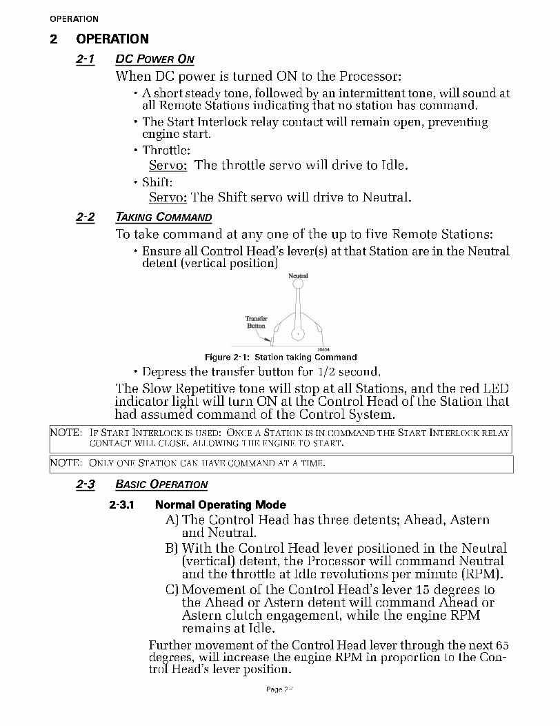
To take command at any one of the up to five Remote Stations:• Ensure all Control Head’s lever(s) at that Station are in the Neutral
detent (vertical position)
• Depress the transfer button for 1/2 second.
The Slow Repetitive tone will stop at all Stations, and the red LED indicator light will turn ON at the Control Head of the Station that had assumed command of the Control System.
2-3 BASIC OPERATION
2-3.1 Normal Operating Mode
A) The Control Head has three detents; Ahead, Astern and Neutral.
B) With the Control Head lever positioned in the Neutral (vertical) detent, the Processor will command Neutral and the throttle at Idle revolutions per minute (RPM).
C) Movement of the Control Head’s lever 15 degrees to the Ahead or Astern detent will command Ahead or Astern clutch engagement, while the engine RPM remains at Idle.
Further movement of the Control Head lever through the next 65 degrees, will increase the engine RPM in proportion to the Con-trol Head’s lever position.
Figure 2-1: Station taking Command
NOTE: IF START INTERLOCK IS USED: ONCE A STATION IS IN COMMAND THE START INTERLOCK RELAY CONTACT WILL CLOSE, ALLOWING THE ENGINE TO START.
NOTE: ONLY ONE STATION CAN HAVE COMMAND AT A TIME.

OPERATION
Page 2-2
2-4 START INTERLOCK (IF USED)
The engine start signal is blocked unless all of the following are true:
• DC power has been turned ON to the Control System. (Reference Sec-tion 2-1, page 2-1)
• A Remote Station is in command. (Reference Section 2-2, page 2-1)
• The Control System is commanding Neutral.
2-5 STATION TRANSFER
Command can be transferred as follows:A) The Station-in-Command’s lever(s) may be left in any posi-
tion.
B) Place the Control Head’s lever(s) of the receiving Station in the Neutral/Idle detent position (refer to Figure 2-3:).
Figure 2-2: Control Head Detents
WARNING: PERSONAL INJURY COULD OCCUR IF THE FOLLOWING STEPS ARE NOT FOLLOWED
EXACTLY.
Figure 2-3: Remote Stations Before Transfer of Command
Figure 2-4: Remote Station Transfer after Transfer of Command
C) At the Station taking command (receiving Station), depress and hold the transfer but-ton for 1/2 second (refer to Figure 2-4:).• The red LED indicator light at the receiving
Station’s Control Head will illuminate, indi-cating that the Station has taken command.
• The red LED indicator light will go OFF at the transferring Station’s Control Head, indicating that the Station no longer is in command.
• The commanded positions of the Throttle and Clutch will remain unchanged for one second after the red LED lights. This allows the operator time to move the Con-trol Head’s lever(s) to a position approxi-mately matching the last Station, which will allow the vessel to maintain present speed and direction.
OPERATION
Page 2-3
2-6 PROPORTIONAL PAUSE
The proportional pause provides a means of safely reversing the vessel’s direction. A variable pause is introduced into the clutch command signal to allow time for the engine RPM’s to drop to Idle and for the vessel’s speed through the water to slow.
(Refer to MM9000-I Installation Manual for details)
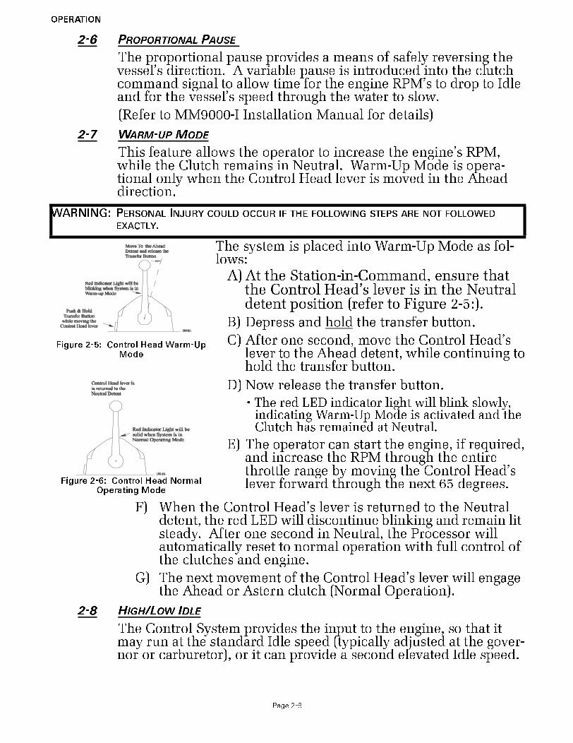
2-7 WARM-UP MODE
This feature allows the operator to increase the engine’s RPM, while the Clutch remains in Neutral. Warm-Up Mode is opera-tional only when the Control Head lever is moved in the Ahead direction.
F) When the Control Head’s lever is returned to the Neutral detent, the red LED will discontinue blinking and remain lit steady. After one second in Neutral, the Processor will automatically reset to normal operation with full control of the clutches and engine.
G) The next movement of the Control Head’s lever will engage the Ahead or Astern clutch (Normal Operation).
2-8 HIGH/LOW IDLE
The Control System provides the input to the engine, so that it may run at the standard Idle speed (typically adjusted at the gover-nor or carburetor), or it can provide a second elevated Idle speed.
WARNING: PERSONAL INJURY COULD OCCUR IF THE FOLLOWING STEPS ARE NOT FOLLOWED
EXACTLY.
Figure 2-5: Control Head Warm-Up Mode
The system is placed into Warm-Up Mode as fol-lows:
A) At the Station-in-Command, ensure that the Control Head’s lever is in the Neutral detent position (refer to Figure 2-5:).
B) Depress and hold the transfer button.
C) After one second, move the Control Head’s lever to the Ahead detent, while continuing to hold the transfer button.
Figure 2-6: Control Head Normal Operating Mode
D) Now release the transfer button.
•The red LED indicator light will blink slowly, indicating Warm-Up Mode is activated and the Clutch has remained at Neutral.
E) The operator can start the engine, if required, and increase the RPM through the entire throttle range by moving the Control Head’s lever forward through the next 65 degrees.

OPERATION
Page 2-4
2-8.1 Low Idle
• The factory default setting is for Low Idle Only.
• When the System is initially powered-up, it will always com-mand Low Idle, even when High Idle is selected.
2-8.2 High Idle
• If High Idle is desired, it may be programmed during Dock Tri-als.
• High Idle is programmable up to a maximum setting of 20% of Full Throttle.
• High Idle is automatically selected when in Warm-Up Mode.
2-8.3 Selecting Between High and Low Idle
Refer to Figure 2-7: when selecting between Low and High Idle (or vice versa) at the Station-in-Command.
C) To return to the previous Idle setting, depress and hold the transfer button again for 1/2 second and then release.
2-9 ONE LEVER MODE (TWIN SCREW)
The system supports a mode of operation referred to as One Lever Mode, which allows the operator to control both engines and transmissions with a single Control Head lever. The Port or the Starboard lever at any Remote Station can be designated by the operator as the Master lever. The designation can be changed by the operator at any time. Most of the features (synchronization, troll, etc.) available in normal operation are available while operat-ing in One Lever Mode.
• The Processor defaults to One Lever Mode disabled.
• One Lever Mode can be disabled or enabled in the Set Up Proce-dures.
WARNING: PERSONAL INJURY COULD OCCUR IF THE FOLLOWING STEPS ARE NOT FOLLOWED
EXACTLY.
Figure 2-7: High/Low Idle Mode Selection
A) The Control Head’s lever(s) may be in the Neutral, Ahead or Astern detents when making a selection.
B) Depress and hold the transfer button for 1/2 second and then release.• If the System was in Low Idle it will toggle to
High Idle, and vice versa.
NOTE: IN TWIN SCREW APPLICATIONS, ALWAYS PROGRAM BOTH PROCESSORS FOR THE SAME AMOUNT OF HIGH IDLE. IN TWIN SCREW APPLICATIONS, BOTH THE PORT AND STARBOARD PROCESSORS WILL ALWAYS BE IN HIGH OR LOW IDLE AT THE SAME TIME.
NOTE: ONE LEVER OPERATION MAY BE USED IN TROLL MODE OR IN NON-TROLL MODE.
NOTE: THE GREEN LED WILL ALWAYS BE LIT WHILE IN ONE LEVER OPERATION, NO MATTER WHAT POSITION THE MASTER CONTROL HEAD LEVER IS IN.
Depress and Hold Transfer Buttonfor ½ second to toggle betweenHigh and Low Idle
10238
Control Head levers may bein Neutral, Ahead,or Astern Detent

OPERATION
Page 2-5
• When One Lever Mode is enabled, the operation must be turned ON and OFF as described below.
2-9.1 Turning ON One Lever Operation
2-9.2 Turning OFF One Lever Operation
A) Place the Master lever into the Neutral detent.
B) Place the inactive Control Head lever into the Neutral detent.
• Whenever the inactive lever is moved to the Neutral detent, One Lever operation is turned OFF. The green LED will turn OFF, indicating that the control system is now in normal operating mode.
2-10 ENGINE SYNCHRONIZATION (TWIN SCREW)
Engine Synchronization must be selected during Set Up to have automatic synchronization.
Synchronization is automatic and only operates when the Ahead clutch is engaged, consequently it can be left ON full time. When
WARNING: PERSONAL INJURY COULD OCCUR IF THE FOLLOWING STEPS ARE NOT FOLLOWED
EXACTLY.
Figure 2-8: Step A) One Lever Operation Mode
A) At the Station-in-Command, move the Port and Starboard Control Head levers to the Ahead detent.
B) Depress and Hold the transfer button while moving the Port or Starboard Control Head’s lever out of the Ahead detent. Do
Not Release the Transfer Button until the green LED turns ON, indicating One Lever Operation is now active.
Figure 2-9: Step B) One Lever Operation Mode
• The Control Head lever which the operator chose to move out of the Ahead detent, becomes the Master lever.
• The Control Head lever which was left in the Ahead detent is now inactive.
NOTE: THE CONTROL HEAD LEVER DESIGNATED BY THE OPERATOR TO BE INACTIVE IN ONE LEVER OPERATION, MAY BE LEFT IN THE AHEAD DETENT OR MOVED FULLY FORWARD. MOVING THE LEVER FULLY FORWARD IS RECOMMENDED, BECAUSE IT MOVES IT OUT OF THE WAY AND PRE-VENTS ACCIDENTAL BUMPS WHILE OPERATING.
WARNING: IT IS STRONGLY RECOMMENDED THAT THE MASTER LEVER IS RETURNED TO THE NEU-
TRAL/IDLE POSITION PRIOR TO TURNING OFF ONE LEVER OPERATION.
DO NOT ATTEMPT TO TRANSFER COMMAND FROM ONE REMOTE STATION TO ANOTHER
WHILE IN ONE LEVER OPERATION. ALWAYS TURN ONE LEVER OPERATION OFF PRIOR
TO TRANSFERRING.
FAILURE TO OBSERVE THESE RECOMMENDATIONS MAY RESULT IN A SUDDEN CHANGE
IN THE VESSEL’S DIRECTION.
NOTE: THE CONTROL SYSTEM OFFERS TWO TYPES OF SYNCHRONIZATION, ACTIVE OR EQUAL THROT-TLE.

OPERATION
Page 2-6
synchronization has been selected during set up, the Control Sys-tem will always power-up with synchronization ON.
In order for synchronization to become active and work toward synchronizing the engines' RPM's, the Synchronization Criteria listed below must be met.
Synchronization Criteria• Both Control Heads must be commanding 5% or greater of the
throttle range.
• The Control Head levers must be within 10% of one another (+/- approximately 6 degrees).
• Both Control Head levers are commanding Ahead clutch engage-ment.
2-10.1 Synchronization Types
The following types of synchronization use the same criteria, indications, and are turned ON and OFF as described in follow-ing Sections.
2-10.1.1 Equal Throttle Synchronization (Twin Screw) (default)
Equal Throttle synchronization simply positions the throt-tle push-pull cables to the same distance when the criteria has been met. With Equal Throttle Synchronization the Processors do not receive tachometer signals representative of the engines RPM's.
NOTE: THE USE OF VALUE 03 FOR FUNCTION CODE E7 SHOULD BE AVOIDED IN THE 9000 SERIES PROCESSORS WITH MECHANICAL THROTTLE CONTROL.
SYMPTOM:WHEN SELECTED, VALUE 03 (ACTIVE SYNCHRONIZATION, NO SYNCH IF TACH SIGNAL LOST) FOR FUNCTION CODE E7 (SYNCHRONIZATION) MAY GIVE THE OPERATOR THE APPEARANCE THAT SYN-CHRONIZATION IS NOT FUNCTIONING. THIS IS DUE TO THE FACT THAT THE CONTROL HEAD’S GREEN SYNCH INDICATION LED DOES NOT LIGHT UNTIL BOTH ENGINE RPM’S ARE WITHIN THE “ACTIVE SYNCH DEAD-BAND”. “ACTIVE SYNCH DEADBAND” IS THE MAXIMUM ALLOW-ABLE DIFFERENCE IN ENGINE RPM, WHERE THE PROCESSORS CONSIDER THE SYSTEM SYN-CHRONIZED ADEQUATELY. ONCE OBTAINED, THE CONTROL SYSTEM DOES NOT ATTEMPT TO MATCH
THE RPM’S ANY CLOSER.WHEN IN THIS MODE OF OPERATION, THERE IS NO INDICATION TO THE OPERATOR THAT THE CONTROL HEAD LEVERS ARE MATCHED CLOSE ENOUGH TO START THE SYNCHRONIZATION PROCESS. ADDITIONALLY, THE GREEN INDICATION LED DOES NOT BLINK WHILE WORKING TOWARD SYNCHRONIZATION.
CAUSE:
FUNCTION CODE E7, VALUE 03, IS OPERATING AS DESIGNED. DUE TO THE IMPRECISE POSITIONING OF MECHANICAL PUSH-PULL CABLES, THE ABILITY TO POSITION THE CABLES WITHIN THE “ACTIVE SYNCH DEADBAND” IS SEVERELY IMPAIRED.
SOLUTION:
ALL PROCESSORS WITH MECHANICAL THROTTLE CONTROL, WHERE SYNCHRONIZATION IS DESIRED, MUST SET THE VALUE OF FUNCTION CODE E7 TO VALUE 01 (ACTIVE SYNCHRONIZATION REVERTS TO EQUAL THROTTLE SYNCHRONIZATION IF TACH SIGNAL IS LOST)

OPERATION
Page 2-7
2-10.1.2 Active Synchronization (Twin Screw)(default Disabled)
Active Synchronization must be enabled during Set Up and a Tach Sensor Wire Harness must be used.
The Processors each receive a tachometer signal represent-ing engine RPM from their respective engines. These sig-nals are compared with one another over a serial communication line. If the Synchronization Criteria is met, the throttle command signal of the engine running at the higher RPM is lowered, until the RPM's of both engines match.
2-10.2 Synchronization Indications
The green LED located on the Control Head indicates the status of synchronization.
• In Active Synchronization the green LED blinks every time there is a change in the commanded throttle.
• When the green LED is lit steady, the engines are synchronized.
• When the green LED is not lit, the engines are not synchronized and the Control System is not attempting to do so.
2-10.3 Turning Synchronization OFF:
A) Ensure that the Control Head's levers are positioned to a point where Synchronization Criteria are met.
B) Press and hold the transfer button until the green LED blinks twice and then goes out (approximately 2 seconds).
C) Synchronization is now OFF.
2-10.4 Turning Synchronization ON:
A) Ensure that the Control Head's levers are positioned to a point where Synchronization Criteria are met.
B) Press and hold the transfer button until the green LED lights (approximately 2 seconds).
• The green LED will blink as the system is working toward syn-chronization.
• The green LED will become solid when the engines are synchro-nized.
CAUTION: The Control System will remain synchronized as long as the Control Head's levers are in close proximity to one another. If a lever is moved to a point where the 10% throttle window is exceeded, a 10% increase in engine RPM would occur with one engine, resulting in a sudden change in the vessel's direction.
NOTE: IN ORDER FOR EQUAL THROTTLE SYNCHRONIZATION TO WORK PROPERLY, THE BENDS IN THE PUSH-PULL CABLES MUST BE KEPT TO A MINIMUM. THERE CAN BE NO BACK-LASH IN THE LINK-AGE OR CABLES. BOTH GOVERNORS OR CARBURETORS MUST PROVIDE EQUAL ENGINE RPM WITH EQUAL MOVEMENT OF THEIR SELECTOR LEVERS. IF THESE CONDITIONS CAN NOT BE MET, ACTIVE SYNCHRONIZATION IS RECOMMENDED.

OPERATION
Page 2-8
2-10.5 Turning Synchronization ON and OFF when Control Head Levers are not within a 10% (6 degree) Window of One Another:
The actual synchronizing of the engines occurs when the Control Head levers are within the 10% (approximately 6 degrees) win-dow of one another. However, synchronization can be turned ON or OFF when the Control Head levers are apart more than the 10% (approximately 6 degrees) window of one another.
• When synchronization is turned ON by pressing the transfer but-ton, the green LED will light after two seconds and stay lighted as long as the transfer button is depressed.
• When turning OFF synchronization by pressing the transfer but-ton for two seconds, the green LED will blink twice indicating that synchronization is turned OFF.
2-11 CONTROL SYSTEM’S CONFIGURABILITY
The Processor is designed in a way which allows it to be easily configured by the installer to meet the varying needs of a wide variety of vessels. Below you will find a list and a brief descrip-tion of the groups of these functions.
2-11.1 Processor Functions
Within this section of adjustable parameters, there are up to five different adjustments:
A0 Processor Identification - Assigns each Processor in multi-screw application a unique identifying number. This function must be the second function set dur-ing Set Up.
A1 Number of Engines - Lets the Processor know how many other Processors need to be communicated with. This function must be the first function set during Set Up.
A2 One Lever Operation - Allows the installer to disable or enable One Lever Mode capability.
A3 Station Expander - Allows the Processor to communi-cate with the Station Expander (SE).
A4 Neutral Indication Tone - When turned ON, produces a short 200 Hz tone to indicate Neutral.
Detail information on each function is found in the MM9000-I Installation Manual.
2-11.2 Throttle Functions
2-11.2.1 Basic Throttle Functions
This section applicable to both electronic and servo Throt-tle adjustment:
E1 Throttle in Neutral - Adjusts the position of the Throttle while in Neutral
E5 Throttle Pause following Shift - Allows a pause prior to applying speed above Idle.
E6 High Idle - Programs a second elevated Idle RPM.

OPERATION
Page 2-9
E7 Synchronization - Allows the installer to select synchronization and select the type of syn-chronization.
Detail information on each function is found in the MM9000-I Installation Manual.
2-11.2.2 Servo Throttle Functions
This section along with Basic Throttle Functions allows the adjustment of the Servo Throttle:
E0 Engine Throttle Profile - Select whether the Throt-tle Servo pushes or pulls to increase speed.
E2 Throttle Minimum - Once set mechanically at the Idle stop, this Function Code allows the posi-tion of the push-pull cable to be adjusted electrically in order to eliminate "dead lever". Dead lever in this case can be described as a movement of the Control Head lever without a change in the engine’s RPM.
E3 Throttle Maximum - Adjusts the position or amount of travel of the push-pull cable at Full Throttle.
E4 Throttle Maximum Astern - Limits the amount of the Astern Throttle Servo movement.
Detail information on each function is found in the MM9000-I Installation Manual.
2-11.3 Clutch Functions
2-11.3.1 Basic Clutch Functions
The following functions are available for all types of clutches.
C0 Clutch Pressure Interlock - Selects the Clutch Pressure Interlock option.
C1 Clutch Interlock Delay - Determines when the Clutch Pressure Interlock becomes active.
C2 Proportional Pause - Selects between an In-Gear, Neutral, or Fixed Neutral delay.
C3 Proportional Pause Time - Selects the maximum delay during a full speed reversal.
C4 Proportional Pause Ratio - Determines if the Ahead and Astern reversal times are the same or if Astern is one half of Ahead.
Detail information on each function is found in the MM9000-I Installation Manual.
2-11.3.2 Clutch Servo Functions
This section along with the Basic Clutch Functions Section allows the adjustment of Clutch servo related items:
C5 Clutch Servo Direction - Determines if the servo pushes or pulls for Ahead and Astern.

OPERATION
Page 2-10
C6 Clutch Ahead - Adjusts the amount of clutch servo travel in Ahead.
C7 Clutch Astern - Adjusts the amount of clutch servo travel in Astern.
Detail information on each function is found in the MM9000-I Installation Manual.
2-11.4 Troll Functions
Refer to the 9001 Troll Actuator Manual (p/n MM9001) for detailed information on the Troll Functions and their operation.
2-11.5 Troubleshooting Functions
2-11.5.1 Basic Troubleshooting Functions
H0 Diagnostics - Allows the installer/technician to look at various inputs to the Processor.
H1 Return to Factory Defaults - Returns all settings to the factory default values.
Detail information on each function is found in the MM9000-I Installation Manual.
2-12 AUDIBLE TONES
2-12.1 Basic Processor Tones
The Processor can produce numerous tones which inform the operator of the status of the system or if any faults were to occur. These tones are emitted from all Remote Stations regardless of whether they are in command or not.
2-12.1.1 Slow Repetitive Tone
Detail information on this tone is in Appendix B.
This tone is normal when DC power is first applied to the System. This tone indicates that system initialization has occurred, no Remote Station has command, the operator can accept command at any Remote Station.
2-12.1.2 One Long, Three Short Tones
Detail information on this tone is in Appendix B.
This tone indicates that the command signal from a Control Head’s potentiometer has gone out of range.
2-12.1.3 Steady Tone
Detail information on this tone is in Appendix B.
This tone indicates that the software program within the Processor has quit running, due to low voltage or compo-nent failure.
Figure 2-10: Slow Repetitive Tone
Figure 2-11: One Long, Three Short Tones
Figure 2-12: Steady Tone

OPERATION
Page 2-11
2-12.1.4 Five (5) Second Steady Tone
Detail information on this tone is in Appendix B.
This tone indicates that there has been a loss of Serial Com-munication.
2-12.1.5 Three (3) Second Steady Tone
Detail information on this tone is in Appendix B.
This tone is heard if there is a stuck transfer button, or when entering Back-up Mode, or if a Troll Solenoid error occurs. (Back-up Mode and Troll Solenoid is not available for all Processors.)
2-12.1.6 Five Seconds On, Five Seconds Off - High Repetitive Rate Tone
Detail information on this tone is in Appendix B.
This tone indicates that Function Code A3 Station Expander (SE) has had the value 01 Enabled entered, but the Processor and Station Expander cannot communicate.
2-12.2 Throttle (Servo 2) Tones
The following Tones are in addition to the Basic Processor Tones.
2-12.2.1 One Long - Two Short Tones
Detail information on this tone is in Appendix B.
This tone indicates that the feedback potentiometer signal from Servo 2 (Throttle) has gone out of range.
2-12.2.2 One Long, Two Short - High Repetitive Tone
Detail information on this tone is in Appendix B.
This tone indicates that Servo 2 (Throttle) cannot reach the commanded position. This tone is also referred to as Servo 2 Jam Tone.
2-12.3 Clutch (Servo 1) Tones
The following Tones are in addition to the Basic Tones listed in Section 2-13.1.
2-12.3.1 One Long - One Short Tone
Detail information on this tone is in Appendix B.
Figure 2-13: Five (5) Second Steady Tone
Figure 2-14: Three (3) Second Steady Tone
Figure 2-15: Five Seconds On, Five Seconds Off - High Repetitive Tone
Figure 2-16: One Long - Two Short Tones
Figure 2-17: One Long - Two Short - High Repetitive Tones
Figure 2-18: One Long - One Short Tone
OPERATION
Page 2-12
This tone indicates that the feedback potentiometer signal from Servo 1 (Clutch) has gone out of range.
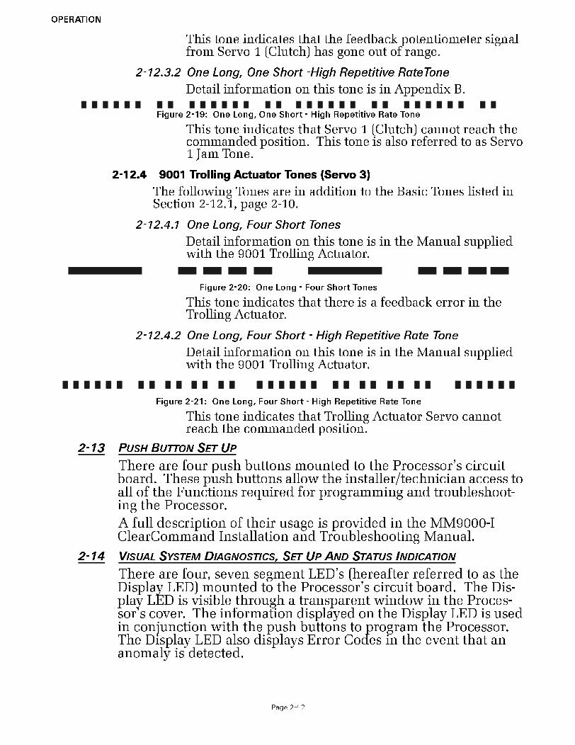
2-12.3.2 One Long, One Short -High Repetitive RateTone
Detail information on this tone is in Appendix B.
This tone indicates that Servo 1 (Clutch) cannot reach the commanded position. This tone is also referred to as Servo 1 Jam Tone.
2-12.4 9001 Trolling Actuator Tones (Servo 3)
The following Tones are in addition to the Basic Tones listed in Section 2-12.1, page 2-10.
2-12.4.1 One Long, Four Short Tones
Detail information on this tone is in the Manual supplied with the 9001 Trolling Actuator.
This tone indicates that there is a feedback error in the Trolling Actuator.
2-12.4.2 One Long, Four Short - High Repetitive Rate Tone
Detail information on this tone is in the Manual supplied with the 9001 Trolling Actuator.
This tone indicates that Trolling Actuator Servo cannot reach the commanded position.
2-13 PUSH BUTTON SET UP
There are four push buttons mounted to the Processor’s circuit board. These push buttons allow the installer/technician access to all of the Functions required for programming and troubleshoot-ing the Processor.
A full description of their usage is provided in the MM9000-I ClearCommand Installation and Troubleshooting Manual.
2-14 VISUAL SYSTEM DIAGNOSTICS, SET UP AND STATUS INDICATION
There are four, seven segment LED’s (hereafter referred to as the Display LED) mounted to the Processor’s circuit board. The Dis-play LED is visible through a transparent window in the Proces-sor’s cover. The information displayed on the Display LED is used in conjunction with the push buttons to program the Processor. The Display LED also displays Error Codes in the event that an anomaly is detected.
Figure 2-19: One Long, One Short - High Repetitive Rate Tone
Figure 2-20: One Long - Four Short Tones
Figure 2-21: One Long, Four Short - High Repetitive Rate Tone

OPERATION
Page 2-13
For a full description of the Display LED, its capability and usage, refer to the MM9000-I ClearCommand Installation and Trouble-shooting Manual.
2-15 PLUGGABLE CONNECTIONS
2-15.1 Standard Pluggable Processor
The standard Processor comes from the factory with five Pigtail Connectors for easy, mistake free pluggable installations. Not all Processors are supplied with all of these pigtails.
The following is a list of the pigtail connectors used in the stan-dard Processor:
• Two Remote Station pigtails. Three additional Stations can be connected directly to the standard Processor.
• One pigtail connector provides the connections for DC Power, Start Interlock, Clutch Pressure Interlock and External Alarm.
• One pigtail connector is provided for serial communication between multiple Processors.
• One pigtail connector is provided for the Tach Sensor input used in synchronization.
Figure 2-22: Circuit Board Shield Layout
Figure 2-23: Standard Processor Pluggable Connections View
Push Button Location
12255
LED Location

OPERATION
Page 2-14
2-16 OPTIONAL FEATURES OPERATION
2-16.1 System Failure External Alarm
• This optional feature is designed to provide a status signal to an external alarm circuit.
• The status signal is in the form of an open or closed relay con-tact. When the contact is closed, the Processor is functioning normally. When the contact opens, this indicates the software program has quit running due to a component failure or loss of DC power.
• A full explanation is provided in the MM9000-I ClearCom-mand Installation and Troubleshooting Manual.
2-16.2 Clutch Pressure Interlock
• The purpose of the Clutch Pressure Interlock is to prevent high engine RPM when the Clutch is not fully engaged.
• A full explanation is provided in the MM9000-I ClearCom-mand Installation and Troubleshooting Manual.
2-16.3 Station Expander (SE)
• The SE is a separate Processor housed in an enclosure that allows the connection of up to five additional Remote Control Stations.
• The SE communicates with the Processor over the serial com-munication line.
• A full explanation of the installation, operation and adjust-ment of the SE is provided in the Installation Manual provided with the SE.
• Additional information can be found in the MM9000-I ClearCommand Installation and Troubleshooting Manual.
2-16.4 Multiple Screw Installations
This Manual, as written, is intended for Single and Twin Screw applications only.
The Processor has the capability of controlling Triple, Quad and Quint Screw vessels. In order to do so, contact your ZF Mathers representative for the required information and materials.
2-16.5 9001 Mechanically Actuated Trolling Valve Control
• The purpose of a Trolling Valve is to lower the Clutch pres-sure, which allows the Clutch Plate to slip.
• A full explanation is provided in the Installation Manual pro-vided with the 9001 Trolling Actuator.
• Further information on Trolling Valve Control can be found in MM9000-I ClearCommand Installation and Troubleshooting Manual.

PLAN THE INSTALLATION
Page 3-1
3 PLAN THE INSTALLATION
Refer to MM9000-I Installation and Troubleshooting manual for ClearCommand’s basic hardware and software Plan the Installa-tion. The following Sections are unique to the Control Processor supplied with your System.
NOTE: ZF MATHERS RECOMMENDS THAT THE SYSTEM BE INSTALLED IN ACCORDANCE WITH ABYC, E-11 AND P24.

INSTALLATION
Page 4-1
4 INSTALLATION
Refer to MM9000-I Installation and Troubleshooting manual for ClearCommand’s basic hardware and software Installation. The following Sections are unique to the Control Processor supplied with your System.
NOTE: BEFORE STARTING THE ACTUAL INSTALLATION OF THE CONTROL SYSTEM, MAKE SURE YOU HAVE THE CORRECT PARTS AND TOOLS ON HAND. REFER TO MM9000-I PLAN THE INSTALLA-TION SECTION. READ ALL THE INSTRUCTIONS PERTINENT TO EACH PART BEFORE BEGINNING THE INSTALLATION OF THE PART.
CAUTION: Static electricity can destroy electronic components. Connect the wrist strap provided, to the Processor frame whenever working on the Processor with the enclosure cover open. This will drain any static charge you may have on your person.

SET UP PROCEDURES
Page 5-1
5 SET UP PROCEDURE
The Processor utilizes push buttons in conjunction with Display LED’s to program, adjust, calibrate and set up the various fea-tures. The push buttons also allow you to access and display information regarding the health of the System. Refer to the MM9000-I Installation and Troubleshooting Manual for an explaination on how to locate and use the push buttons and Dis-play LEDs. The following Sections are unique to the Control Processor supplied with your System.

DOCK TRIALS
Page 6-1
6 DOCK TRIALS
Perform the Dock Trial Sections located in the MM9000-I Instal-lation and Troubleshooting Manual. Ensure that all tests are complete and correct before going on Sea Trials.
WARNING: IT IS IMPERATIVE THAT THE INFORMATION PROVIDED IN THE PREVIOUS SECTIONS AND THE MM9000-I INSTALLATION MANUAL HAVE BEEN READ AND FOLLOWED PRE-
CISELY, PRIOR TO ATTEMPTING A DOCK TRIAL.
CAUTION: With I/O or Outboard applications, do not attempt to shift into or out of gear with engines stopped. This may cause a jam condition or damage to the linkage to some clutch configurations.
NOTE: ON TWIN SCREW APPLICATIONS, THE FOLLOWING TESTS MUST BE PERFORMED ON BOTH SIDES. IF ANY OF THE FOLLOWING TESTS FAIL, CONSULT APPENDIX B TROUBLESHOOTING.

SEA TRIALS
Page 7-1
7 SEA TRIALS
7-1 FULL SPEED SETTING - SERVO THROTTLE
A) Warm-up the engine(s) and transmission(s) and slowly move into open water.
B) Gradually move the lever(s) to Full speed.
C) If synchronization is installed, disable synchronization as explained in MM9000-I Installation Manual.
• If the engine RPM is low, check whether the engine throttle lever is against the full speed stop.
• If the engine RPM is high, decrease by using Function Code E3, as explained in MM9000-I Installation Manual.
D) For twin screw applications, check that matching Idle, Mid-range and Full speed Control Head lever positions cause equal RPM in both engines.• If RPM’s do not match, check push-pull cable travel. If travel
does not match when the Control Head levers are side by side, adjust Function Code E3 Throttle Maximum, as explained in MM9000-I Installation Manual.
7-2 PROPORTIONAL PAUSE
The proportional pause feature provides engine deceleration when making a direction change. The pause is variable and in proportion to:
• The Control Head’s lever position prior to the reversal.
• How long the Control Head’s lever has been in that position prior to the reversal.
The pause is In-Gear or at Neutral, depending on the Function Code C2 Proportional Pause setting. The sequence of events, are as follows for the three different Reversal Pause types:
7-2.1 In-Gear Delay [C200]
• The Throttle position drops to Idle.
• The Transmission remains engaged in Ahead or Astern.
• The Control System pauses at this position until the delay has timed out.
WARNING: IT IS IMPERATIVE THAT THE INFORMATION PROVIDED IN THE PREVIOUS SECTIONS HAS BEEN READ AND FOLLOWED PRECISELY, PRIOR TO ATTEMPTING A SEA TRIAL. IF ANY OF THE FOLLOWING TESTS FAIL, DISCONTINUE THE SEA TRIAL IMMEDIATELY AND RETURN TO THE DOCK. CONSULT APPENDIX B TROUBLESHOOTING SECTION OR A ZF FACILITY PRIOR TO RESUMING THE SEA TRIAL.
NOTE: ON TWIN SCREW APPLICATIONS, THE FOLLOWING TESTS MUST BE PERFORMED ON BOTH SIDES. DURING THE COURSE OF THE DOCK TRIAL AND SEA TRIALS, FILL OUT THE TRIAL REPORT. RETAIN THIS INFORMATION FOR FUTURE USE.

SEA TRIALS
Page 7-2
• The Transmission shifts to the opposite gear (Astern or Ahead).
• The Throttle position moves to the Control Head’s present lever position.
7-2.2 Neutral Delay [C201]
• The Throttle position drops to Idle.
• The Transmission shifts to Neutral.
• The Control System pauses at this position until the delay has timed out.
• The Transmission shifts to the opposite gear (Astern or Ahead).
• The Throttle position moves to the Control Head’s present lever position.
7-2.3 Fixed Neutral Delay [C202]
• The Throttle drops to Idle.
• The Transmission shifts to Neutral.
• The Control System pauses at this position for the amount of time programmed (duration) with Function C3 Propor-tional Pause Time (regardless of prior throttle setting).
• The Transmission shifts to the opposite gear (Port or Star-board)
• The Throttle position moves to the Control Head’s present commanded position.
7-2.4 Calculating Proportional Pause Time C3
The amount of pause required is determined as follows:
A) Place the Control Head lever(s) to the Full Ahead position.
B) Leave the Control Head lever(s) at this position for whichever of the following two is longer:
• Sixty seconds.
CAUTION: The Fixed Neutral Delay feature was added in order to accommodate Thruster Control installations. Damage to the drive train may occur when used for reverse reduction gear applications.
NOTE: THE PAUSE ON A THROUGH NEUTRAL SHIFT IS PROPORTIONAL TO THE SPEED COMMANDED AND THE TIME AT THAT SPEED. THE VALUES LISTED FOR FUNCTION CODE C3, PROPORTIONAL PAUSE TIME, ARE THE MAXIMUM POSSIBLE DELAYS. WHEN SHIFTING FROM IDLE AHEAD TO IDLE ASTERN OR VICE-VERSA THE DELAY IS ZERO. THE TIME REQUIRED TO BUILD UP TO THE MAXIMUM PAUSE IS SIX TIMES THE VALUE SELECTED. IN ADDITION, IN ORDER TO BUILD UP TO THE MAXIMUM DELAY VALUE, THE SYSTEM MUST BE COMMANDING FULL THROTTLE. THE PAUSE WHEN SHIFTING FROM ASTERN TO AHEAD IS EITHER HALF OR THE SAME AS THE AHEAD TO ASTERN DELAY DEPENDING ON THE VALUE SELECTED FOR FUNCTION CODE C4 PROPOR-TIONAL PAUSE RATIO.
NOTE: A STOP-WATCH IS REQUIRED TO ACCURATELY PROGRAM THE PROPORTIONAL PAUSE TIME.

SEA TRIALS
Page 7-3
• The vessel’s speed through the water reaches maxi-mum.
C) Quickly move the Control Head lever(s) to Ahead Idle or Neutral, (depending on Function Code C4 set-ting) while starting the stop-watch.
D) When the engine(s) RPM reaches Idle and the ves-sel’s speed through the water is within two knots of the standard Idle Ahead speed, stop the stop-watch.
E) Program Function Code C3, Proportional Pause Time, as described in the Set Up Procedures, to the time expired on the stop-watch.
7-2.5 Testing The Proportional Pause
A) Position the boat in open water and slowly increase the Throttle to 25% of the speed range.
B) Leave the Control Head lever(s) at this position for at least 60 seconds.
C) Quickly move the Control Head lever(s) to Idle Astern.• The engine(s) RPM should drop to Idle.
• The Clutch should stay engaged or shift to Neutral for 25% of the time selected with Function Code C3 Proportional Pause Time.
• Once the time has expired, the Clutch should Shift to Astern.
• The engine RPM will drop slightly when the Astern load is placed on the engine, but not to the point where it comes close to stalling.
D) Increase the Throttle slightly until the vessel starts mov-ing in the opposite direction.
• If the engine stalled or came very close to stalling, increase the Value of Function Code C3 by one second. Repeat steps A) through C).
• If the engine does not stall or come close to stalling, pro-ceed with the next step.
E) Repeat steps A) through D) with the Throttle at 50%, 75%, and 100% of the speed range.
• If the engine stalls at any time, increase the Value of Function Code C3 by one second and repeat the steps A) through D) again.
F) Once a Full Speed Reversal is successful without com-ing close to stalling, the Proportional Pause is properly adjusted.
CAUTION: It is critical that the Proportional Pause is tested as outlined below to ensure that it was properly programmed. Failure to do so could cause dam-age to the transmission.

SEA TRIALS
Page 7-4
7-3 SYNCHRONIZATION TEST (TWIN SCREW ONLY)
7-3.1 Equal Throttle Synchronization
A) Move both Control Head levers side by side to approxi-mately 25% of the Throttle range.
B) If previously disabled, enable the synchronization by depressing the transfer button for two seconds.
• The green LED on the Control Head should illuminate, indicating synchronization.
C) Check the engine tachometers to see if they are within 1% of one another.
D) Move both Control Head levers side by side to approxi-mately 50% of the Throttle range.
E) Check the engine tachometers to see if they are within 1% of one another.
F) Move both Control Head levers side by side to approxi-mately 75% of the Throttle range.
G) Check the engine tachometers to see if they are within 1% of one another.
H) Move both Control Head levers side by side to 100% of the Throttle range.
I) Check the engine tachometers to see if they are within 1% of one another.
• While synchronized, if the tachometers have a greater than 1% difference at any engine RPM, Active Synchronization is recommended.
7-3.2 Active Synchronization
A) Move both Control Head levers side by side to approxi-mately 25% of the Throttle range.
B) If previously disabled, enable the synchronization by depressing the transfer button for two seconds.
• The green LED on the Control Head may blink while driv-ing toward synchronization.
• Once the engine RPM’s are within 1% of one another, the green LED will remain solidly lit.
C) Check the engine tachometers to see if they are within 1% of one another.
D) Move both Control Head levers side by side to approxi-mately 50% of the Throttle range.
E) Check the engine tachometers to see if they are within 1% of one another.
F) Move both Control Head levers side by side to approxi-mately 75% of the Throttle range.
G) Check the engine tachometers to see if they are within 1% of one another.

SEA TRIALS
Page 7-5
H) Move both Control Head levers side by side to 100% of the Throttle range.
I) Check the engine tachometers to see if they are within 1% of one another.
While synchronized, if the tachometers have a greater than 1% percent difference at any engine RPM, or if they appear to be continually “hunting” for the correct RPM, refer to the Appendix B, B9 Troubleshooting Section.
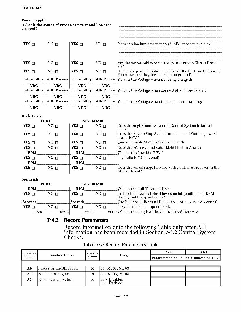
7-4 SEA TRIAL REPORT
The purpose of this Sea Trial Report is to provide a convenient checklist and record of installation, dock trial set up, and sea trial performance of the ZF Mathers Propulsion Control System. Please enter ALL of the information. We recommend that this form remains aboard the vessel, and a copy is sent to ZF Mathers with the Warranty Registration located at the end of this manual.
7-4.1 Vessel Information
7-4.2 Control System Checks
Make the following checks prior to applying power to the Proces-sor.
Vessel Name: Hull No. Trial Date:
Vessel Type: Dwg No.:
Installing Yard/Project Manager: Tel:
Owner/Owner’s Representative:: Tel::
ENGINE DATA: Make: Model: HP (KW): RPM:
PROPELLER DATA: No. of Screws: Propeller Type: Fixed Other
GEAR DATA: Make: Model: Ratio:
No. of Remote Stations: Locations: 1. 3.
2. 4.
5.
PORT STARBOARD
_________________ _________________ Processor Serial Numbers
Processor Mounting Location:
YES NO YES NO Is the Processor subject to excessive heat? (Above 70 degrees C)
YES NO YES NO At least 4 feet (1,2m) from strong magnetic fields?
YES NO YES NO Accessible for checkout, adjustments, and maintenance?
YES NO YES NO Are the Processors bonded (grounded)?
YES NO YES NO Are all Electric Cables supported every 18 inches (45,72cm)?
YES NO YES NO Do the Shift and Throttle push-pull cables travel in the correct direction?
YES NO YES NO Is the amount of push-pull cable travel set properly for Shift and Throttle?
YES NO YES NO Are all of the push-pull cable’s fasteners tightened?
YES NO YES NO Are the electrical cable connections tight at the Processors and Control Heads?
YES NO YES NO Is the Processor’s Start Interlock Circuit being used?
YES NO YES NO Is there an Engine Stop Switch installed at each Remote Sta-tion?
SEA TRIALS
Page 7-6
7-4.3 Record Parameters
Record information onto the following Table only after ALL information has been recorded in Section 7-4.2 Control System Checks.
Power Supply:
What is the source of Processor power and how is it charged?
___________________________________________________________________________________________________________________________________________________________________________________________________________________________________________________________________________________
YES NO YES NO Is there a backup power supply? APS or other, explain.____________________________________________________________________________________________________________________________________________________________________________________________________________________________
YES NO YES NO Are the power cables protected by 10 Ampere Circuit Break-ers?
YES NO YES NO If separate power supplies are used for the Port and Starboard Processors, do they have a common ground?
At the Battery____________
VDC
At the Processor____________
VDC
At the Battery____________
VDC
At the Processor____________
VDC
What is the Voltage when not being charged?
At the Battery____________
VDC
At the Processor____________
VDC
At the Battery____________
VDC
At the Processor____________
VDC
What is the Voltage when connected to Shore Power?
At the Battery____________
VDC
At the Processor____________
VDC
At the Battery____________
VDC
At the Processor____________
VDC
What is the Voltage when the engines are running?
Dock Trials:
PORT STARBOARD
YES NO YES NO Does the engine start when the Control System is turned OFF?
YES NO YES NO Does the Engine Stop Switch function at all Stations, regard-less of RPM?
YES NO YES NO Can all Remote Stations take command?
YES NO YES NO Does the Warm-up Indicator Light blink in Ahead?
RPM__________________ RPM__________________What is the Low Idle RPM?
YES NO YES NO High Idle RPM (optional)
RPM__________________ RPM__________________
YES NO YES NO Does the vessel surge forward with Control Head lever in the Ahead Detent?
Sea Trials:
PORT STARBOARD
RPM__________________ RPM__________________What is the Full Throttle RPM?
YES NO YES NO Do the Dual Control Head levers match position and RPM throughout the speed range?
Seconds__________________ Seconds__________________The Full Speed Reversal Delay is set for how many seconds?
YES NO YES NO Is Synchronization operational?
Sta. 1 Sta. 2 Sta. 1 Sta. 2What is the length of the Control Head Harness?
Table 7-2: Record Parameters Table
Function Code
Function NameDefault Value
RangePort Stbd
Programmed Value (as displayed on LCD)
A0 Processor Identification 00 01, 02, 03, 04, 05
A1 Number of Engines 01 01, 02, 03, 04, 05
A2 One Lever Operation 00 00 – Disabled01 – Enabled

SEA TRIALS
Page 7-7
A3 SE (Station Expander) 00 00 – Disabled01 – Enabled
A4 Neutral Indication Tone 00 00 – No Tone01 – Tone upon engaging
Neutral Detent 02 – Tone upon shifting to
Neutral
E0 Throttle Servo Direction 20 20 – Push [Extended] for Throttle Increase
21 – Pull [Retracted] for Throttle Increase
E1 Throttle in Neutral 00.0 00.0 to 25.0% of Throttle Range
E2 Throttle Minimum 00.0 00.0 to 20.0%Will always be 10% or more
below Maximum.
E3 Throttle Maximum 33 10.0 to 100.0%Will always be 10% or more
above Minimum.
E4 Throttle Maximum Astern 100.0 00.1 to 100.0% of Throttle Maximum
E5 Throttle Pause Following Shift
00.5 00.0 to 05.0 Seconds
E6 High Idle 00.0 00.0 to 20.0% of Throttle Maximum
E7 Synchronization 02 00 – Equal Throttle (Open Loop) Synchronization
01 - Active (Closed Loop) Synchronization (reverts to Equal if Tach Signal lost)
02 - No Synchronization03 - Active (Closed Loop)
Synchronization (no synchronization if Tach Signal is lost)
C0 Clutch Pressure Interlock 00 00 – Not Installed01 – Installed02 – Throttle Clutch Pressure
Interlock Mode
C1 Clutch Interlock Delay 01.0 00.5 to 10.0 Seconds
C2 Proportional Pause 00 00 – In-Gear01 – Neutral02 – Fixed Neutral Delay
Enabled (NOTE: If C2 is set to 02, C3 will set Fixed Neutral Delay duration.
C3 Proportional Pause Time 03 00 to 99 Seconds
C4 Proportional Pause Ratio 00 00 – 2:1 Ahead to Astern vs. Astern to Ahead
01 – 1:1 Ahead to Astern vs. Astern to Ahead
C5 Clutch Servo Direction 20 20 – Pull [Retracted] for Ahead
21 – Push [Extended] for Ahead
C6 Clutch Ahead 80 00.0 to 100% of Maximum Ahead Travel from Neu-tral.
Table 7-2: Record Parameters Table
Function Code
Function NameDefault Value
RangePort Stbd
Programmed Value (as displayed on LCD)

SEA TRIALS
Page 7-8
7-4.4 Comments (Please use additional paper as necessary):
7-4.4.1 General Installation Condition
7-4.4.2 Any Irregularities:
INSPECTOR_____________________________________________________
DATE_________________
C7 Clutch Astern 80 00.0 to 100% of Maximum Astern Travel from Neu-tral.
L0 Troll Enable and Control Head Troll Lever Range
00 00 – No Troll01 – 20 Degrees- Type 102 – 35 Degrees- Type 203 – 45 Degrees- Type 3
(Throttle limited to 75%)04 – 55 Degrees - Type 4
(Throttle limited to 10%)
L1 Troll Servo Direction 20 20 – Cable Fully Retracted [Pull] at Lock-up.
21 – Cable Fully Extended [Push] at Lock-up.
L2 Troll Minimum Pressure 70.0 0.01 to 90.0%Will always be at least 10%
below Maximum.
L3 Troll Maximum Pressure 90.0 11.0 to 100.0%Will always be at least 10%
above Minimum.
L4 Troll Throttle Limit 00 00 to 20% of Maximum Throttle.
L5 Troll Pulse Duration 00.6 00.0 to 09.9 Seconds.
L6 Troll Pulse Percentage 90.0 00.0 to 100.0% of available Troll Servo range.
H0 Diagnostic 00 Input Voltage (+/- 0.5VDC)Tachometer Sensor Fre-
quencyStation 1 Lever A/DStation 2 Lever A/DStation 3 Lever A/DStation 4 Lever A/DStation 5 Lever A/DServo 2 Feedback A/DServo 1 Feedback A/DTransfer Button, Stations 1, 2,
3, 4, & 5Software Revision Level
H1 Return to Factory Defaults 00 Store to Return to Factory Defaults
(For Authorized Personnel Only)
Table 7-2: Record Parameters Table
Function Code
Function NameDefault Value
RangePort Stbd
Programmed Value (as displayed on LCD)

SEA TRIALS
Page 7-9

CONTROL OPTIONS
Page 8-1
8 CONTROL OPTIONS
Refer to the Control Option Sections located in the MM9000-I Installation and Troubleshooting Manual.

PERIODIC CHECKS AND MAINTENANCE
Page 9-1
9 PERIODIC CHECKS AND MAINTENANCE
The items listed below should be checked on an annual basis or less, when noted:
9-1 CONTROL HEADS
• Check the terminal strip for signs of corrosion or a loose con-nection.
• If used, disconnect the Deutsch connector and check the pins and sockets for signs of moisture and corrosion.
9-2 PROCESSOR
• Check all terminal connections for signs of corrosion or loose connections.
• Un-plug and inspect all Deutsch connectors for signs of mois-ture or corrosion.
• While in the vicinity of the Processor, move the Station-in-Command’s lever. If the Servo’s are excessively noisy, apply a light coating of silicone grease to the stainless steel lead screws. If there are no Stations in close proximity to the Pro-cessor(s), use a Field Service Control Head or have someone assist.
9-2.1 Throttle Servo Processor
• Check mechanical connections within the Processor and at the Throttle selector lever.
• Check the mechanical movement of the Throttle lever from Idle to Full. Ensure that the cable does not bind while positioning the Throttle at Idle or Full speed.
9-2.2 Clutch Servo Processor
• Check mechanical connections within the Processor and at the Transmission selector lever.
• Check the mechanical movement of the Clutch selector lever from Neutral to Ahead, and Neutral to Astern. Ensure that the cable does not bind while positioning the Control Head lever at Ahead or Astern. Ensure that the Clutch selector lever and the Push-Pull cable form a 90 degree angle at Neutral.
9-3 POWER SUPPLY

PERIODIC CHECKS AND MAINTENANCE
Page 9-2
9-3.1 Battery
The following tests should be performed in the intervals specified:
9-3.1.1 Quarterly (Every 3 Months)
• Check the level of the water (electrolyte) within the Lead-Acid batteries. The plates must be covered. If not, add a small amount of distilled water.
• Check the voltage of the battery. The battery must have a chance to “rest” (no charging and no load for a couple of hours) prior to testing. The following table repre-sents a fully charged battery:
• Check the battery terminals for signs of corrosion, acid build-up or loose connections.
9-3.1.2 Semi-Annually (Every 6 Months)
• Check the specific gravity of your Lead-Acid battery(s) with a Hydrometer. The reading for a fully charged lead acid battery is 1.260 to 1.280.
9-3.1.3 Annually (Every 12 Months)
The tests performed on quarterly and semi-annual basis, give a relatively good indication of the batteries’ health. However, the only way to accurately determine the actual health of your battery is to perform a Battery Load Test.
• There are two types of Battery Load Tests performed in the field, Performance and Service. In order to deter-mine the actual health of your battery a Performance Load Test is recommended. The Service Load Test determines how well your battery performs in the boat and doesn’t take into account the battery’s original rat-ing, which could result in misleading results. The Per-formance Load Test places an accurate load on the battery and compares the results to the battery manu-facture’s specification. The battery should be replaced if the results are 80% or less than the manufacture spec-ifications.
WARNING: BATTERIES CONTAIN SULFURIC ACID AND EMIT HYDROGEN GAS WHILE CHARGING. THEREFORE, SPECIFIC SAFETY PRECAUTIONS MUST BE ADHERED TO WHILE HANDLING AND SERVICING. SPECIFIC INFORMATION ON HANDLING AND SERVICING BATTERIES CAN BE
OBTAINED FROM THE BATTERY COUNCIL INTERNATIONAL, BATTERY SERVICE MANUAL.
CAUTION: In many newer batteries, the vent cap is permanently attached, preventing access to the electrolyte for water level and specific gravity tests. Attempting to pry off these caps could result in premature battery failure.
Table 9-1: Fully Charged Battery
Lead Acid Batteries Gel Cell or AGM Batteries
12V – 12.6 TO 12.8V 12V – 12.4 TO 12.6V
24V – 25.2 TO 25.6V 24V – 25.0 TO 25.4V
WARNING: THE BATTERY LOAD TEST SHOULD BE PERFORMED BY A QUALIFIED MARINE ELECTRI-
CIAN ONLY.

PERIODIC CHECKS AND MAINTENANCE
Page 9-3
9-3.2 Power Cables, Distribution Panels, etc.
• Check all of the connections from the battery to the DC Distribution Panel to the APS for loose or corroded connec-tions.
• Measure the voltage at the battery and at the Processor while the Clutch or Throttle Servo is driving. There should be no more than 10% difference between these two points. If so, check all devices and connections for excessive volt-age drop.
NOTE: IF AN APS IS USED IN THE CIRCUIT TO SUPPLY POWER TO THE PROCESSOR, ACCOUNT FOR THE 0.7V DROP ACROSS THE APS. EXAMPLE: 12.6V @ BATTERY – 1.26V (10% DROP) – 0.7V (APS DROP) = 10.64V (MINIMUM ALLOWABLE VOLTAGE)

APPENDIX A


APPENDIX A
PageA-1
PARTS LIST
PART NO. DESCRIPTION
PROCESSORS (X represents number of remote stations)9110 X Processor (mechanical throttle, mechanical shift) Multi-voltage9001 X Actuator (mechanical troll) Multi-voltage
CONTROL HEADS
SINGLE SCREW
450-3L or 3R Left or Right Control Head, 'T' Lever453-3L or 3R Left or Right Control Head, Chrome Knob Lever455-3L or 3R Left or Right Control Head, Black Low Profile Lever456-3L or 3R Left or Right Control Head, Chrome Low Profile Lever456-3LP or 3RP Left or Right Control Head, Chrome Low Profile Lever, Pluggable
521-4L or 4R Left or Right Control Head, Single Lever Tournament Style - Aluminum521-4LB or 4RB Left or Right Control Head, Single Lever Tournament Style - Aluminum, Junction Box521-5L or 5R Left or Right Control Head, Single Lever Tournament Style - Chrome521-5LB or 5RB Left or Right Control Head, Single Lever Tournament Style - Chrome, Junction Box
750-L or –R Left or Right Control Head, Heavy Duty
MC2000-1L or 1RLeft or Right Black Control Head, Black Single LeverMC2000-2L or 2RLeft or Right Chrome Control Head, Chrome Single LeverMC2000-4L or 4RLeft or Right Black Control Head, Chrome Single LeverMC2000-4LP or 4RPLeft or Right Black Control Head, Chrome Single Lever - PluggableMC2000-5L or 5RLeft or Right Black Control Head, Gold Single Lever
TWIN SCREW (Synchronization Indication)
460-4 Control Head, 'T' Lever 460-4P Control Head, 'T' Lever, Pluggable 463-4 Control Head, Chrome Knob Lever463-4P Control Head, Chrome Knob Lever, Pluggable464-4 Control Heads, Split, with Single Levers, Chrome Knobs (pair)465-4 Control Head, Black Low Profile Lever 466-4 Control Head, Chrome Low Profile Lever
522-4 Control Head, Dual Lever Tournament Style - Aluminum522-4B Control Head, Dual Lever Tournament Style - Aluminum, Junction Box522-5 Control Head, Dual Lever Tournament Style - Chrome522-5B Control Head, Dual Lever Tournament Style - Chrome, Junction Box
760 Control Head, Heavy Duty 760P Control Head, Heavy Duty, Pluggable
MC2000-1 Black Head, Black LeversMC2000-1P Black Head, Black Levers, PluggableMC2000-2 Chrome Head, Chrome LeversMC2000-2P Chrome Head, Chrome Levers, PluggableMC2000-4 Black Head, Chrome LeversMC2000-4P Black Head, Chrome Levers, Pluggable

APPENDIX A
PageA-2
CONTROL HEAD ADAPTER PADS (400 and MC2000 Series Only)
1002 Pad Kit - white, blank 1003 Pad Kit - black, blank1004 Pad Kit - teak, blank1005 Pad Kit - white, machined1006 Pad Kit -black, machined1007 Pad Kit - teak, machined
CABLE (Electric)
180 8-Cond. Shielded Cable Per/ft.350 8-Cond. Shielded Cable 500’ Spool11811 8-Cond. Shielded Cable 1000’ Spool212 2-Cond. Power Cable Per/ft.349 2-Cond. Power Cable 250’ Spool183 2-Cond. Start Interlock Cable Per/ft.355 2-Cond. Start Interlock Cable 250’ Spool
WIRE HARNESS (Plug)Replace the # after the Part Number with the length of harness required. EXAMPLE: 13316-10; 13316-20; 13316-30
13316-# Serial Communication (Twin Screw)
13432-# Throttle, Voltage13494-# Throttle, Current13533-# Throttle, PWM14363-# Throttle, MAN15027-# Throttle, Frequency
13322-# Clutch – Ahead/Astern/Clutch Power13324-# Clutch – Ahead/Astern/Neutral/Clutch Power13240-# Clutch – Ahead/Astern/Troll/Troll CMD/Clutch Power14310-# Clutch – Ahead/Astern/Troll CMD/Clutch Power14925-# MAN with Troll14542-# MAN without Troll
13239-# Magnetic Pickup or Pulse Transmitter
13631-# Power/Start Interlock/Clutch Pressure/Alarm Circuit13552-# Power/Start Interlock/Clutch Pressure13756-# Power/Start Interlock15023-# Power
13557-# Control Head - 1 Connector14261-# Control Head - 2 Connectors
TEST UNIT
13927 Service Field Test Unit14000 Field Test Control Head - Dual

Page A-3
ZF Mathers, LLC12125 Harbour Reach Drive, Suite BMukilteo, WA 98275 U.S.A.800-546-5455 / 425-583-1900Fax: 425-493-1569
MMC-165 Rev.D 3/02
Your ZF Mathers product has been designed and manufactured by experienced engineers and craftsmen. ZF Mathers LLC, warrants for the period indicated below, each product to be free from defect in material and workmanship. Repair or replacement, at ZF Mathers option, will be provided if the product, upon ZF Mathers inspection, is found to be prop-erly installed and operated in accordance with ZF Mathers Manual. This warranty does not apply to malfunction caused by damage, unreasonable use, misuse, repair or service by unauthorized persons or normal wear and tear.A) Coverage Under Warranty
Three years from the date of purchase by the original end user.Year One
No charge for equipment repair, parts and labor. Up to three hours labor toward trou-bleshooting and replacement of defective equipment.Year Two and Three
There is no charge for equipment repairs performed at the factory that are covered under warranty. No labor allowance for troubleshooting and replacement of defective equipment.
B) No Coverage Under WarrantyThe following will not be covered under warranty.Travel to and from the job site.
1. Adjustment or calibration of any ZF Mathers equipment.2. Adjustment or calibration of any associated equipment which may include but not limited to
push-pull cables, engine governor or carburetor, transmission or trolling valve.3. Damage due to accidents, improper installation or handling and or improper storage.4. Damage due to faulty repairs performed by an unauthorized service representative.5. Damage due to conditions, modifications or installation contrary to published specifications or
recommendations.6. Original installation charges or start-up costs.7. Battery service including labor charges related to battery service.8. Rental of equipment during performance of warranty repairs.9. Unauthorized repair shop labor, without prior approval from ZF Mathers Service Department.10. Shop supplies such as connectors, wire, cable, etc.
C) Warranty ServiceCall 1-800-546-5455 or 1-425-583-1900 for your nearest ZF Mathers Factory Authorized Dealer.
1. Prior to returning any product to the factory, you must contact ZF Mathers Service Department for a Material Return Authorization (MRA) number. Return the product freight prepaid, marked clearly with the MRA number and a description of the malfunction.
2. If there is a defect covered by warranty, ZF Mathers will, at its option, either repair or replace the defective part or product. If after inspection, ZF Mathers determines that the product is not defective, ZF Mathers will charge a testing fee and return the product to the sender, freight col-lect.
3. Repair or replacement during the warranty period will not extend the warranty period. 4. All claims must be submitted within 30 days from date of service.5. Claims for over 3 hours must be pre-approved by the ZF Mathers Service Department.
Electronic Propulsion Control Systems Three Year Limited Warranty
THIS WARRANTY IS EXPRESSLY IN LIEU OF ALL OTHER WARRANTIES, EXPRESS OR IMPLIED. EXCEPT TO THE EXTENT PROHIBITED BY APPLICABLE LAW, ZF MATHERS
HEREBY DISCLAIMS ALL OTHER IMPLIED OR EXPRESS WARRANTIES OF ANY KIND, INCLUDING WARRANTIES OF MERCHANTABILITY AND FITNESS FOR A PARTICULAR
PURPOSE. UNDER NO CIRCUMSTANCES SHALL ZF MATHERS BE LIABLE FOR ANY CONSEQUENTIAL DAMAGES SUSTAINED IN CONNECTION WITH THE PRODUCT OR
ITS USE, INCLUDING ANY COSTS OR DAMAGES WHICH RESULT FROM LOSS OF USE OF THE PRODUCT OR ANY ENGINE OR BOAT WITH WHICH IT IS USED. ZF
MATHERS DOES NOT AUTHORIZE ANY REPRESENTATIVE OR AGENT TO ASSUME FOR IT ANY OBLIGATION OR LIABILITY OTHER THAN THOSE EXPRESSLY SET FORTH
ABOVE. SOME STATES DO NOT ALLOW LIMITATIONS ON HOW LONG AN IMPLIED WARRANTY LASTS OR THE EXCLUSION OR LIMITATION OF INCIDENTAL OR CONSE-
QUENTIAL DAMAGES, SO THE ABOVE LIMITATION MAY NOT APPLY TO YOU. ALL IMPLIED WARRANTIES, IF ANY, ARE LIMITED TO THE DURATION OF THIS EXPRESS
WARRANTY. THIS WARRANTY GIVES YOU LEGAL RIGHTS, AND YOU MAY HAVE OTHER RIGHTS WHICH MAY VARY FROM STATE TO STATE.

Page A-4

Page A-5
ZF Mathers, LLC
12125 Harbour Reach Drive, Suite B
Mukilteo, WA 98275 U.S.A.
800-546-5455 / 425-583-1900
Fax: 425-493-1569
MMC-163 Rev.B 1-01
Actuator/Processor, Serial # Serial #
Number of Remote Stations
Purchase Date
Dealer's Name
Installer's Name
Phone Number ( )
Purchaser's Name
Street Address
City, State, Zip
Phone Number ( )
YOUR VESSEL:
Engine, Make & Model
Length
Manufacturer
ZF Mathers, LLC. Product First Seen At:
Boat Show Dealer Magazine Friend
Warranty Registration

Page A-6
ZF Mathers, LLC.
12125 Harbour Reach Drive, Suite B Mukilteo, WA 98275

APPENDIX B


TROUBLESHOOTING
Page B1-1
B1 TROUBLESHOOTING GENERAL
The MicroCommander Control System consists of one Processor per engine, typically mounted in the engine room, and one to five Control Heads located at the vessel’s Remote Stations. The Processor is designed to precisely control speed and direction on vessels equipped with mechanical Throttle and Clutch Selectors.
In the event that a malfunction occurs, review the MicroCom-mander System Diagram above and the descriptions below. Become familiar with the various components, their functions and location on the vessel.
The following is a list of the main components that make up a typical system, along with a brief description of their functions:
B1-1 TYPICAL SYSTEM MAIN COMPONENTS
B1-1.1 Control Head
The primary function of the Control Head is to send out a variable DC voltage to the Processor. This DC voltage is representative of the Control Head’s present lever posi-
Figure B1-1: Basic Single Screw, Two Station Diagram

TROUBLESHOOTING
Page B1-2
tion. In addition to the primary function, the Control Head also has audible (Sound Transducer) and visual (LED) status indications, along with a Transfer Button for taking com-mand and performing other system functions.
B1-1.2 Processor
The Processor receives the variable DC voltage from the Control Head(s) and converts these inputs to the appropri-ate electronic or electric outputs at the correct time and sequence to the Governor and Gear Box. The information regarding throttle type, throttle/ clutch sequencing, etc., are all stored on memory within the Processor.
B1-1.3 Power Source
All electronic equipment must have power in order to oper-ate. Ensuring a properly charged reliable power source is available is crucial. The Processor requires a 12 or 24 VDC power system. The minimum voltage at which the Proces-sor will continue to operate is 8.00 VDC. The maximum allowable voltage is 30 VDC. Exceeding these limits will not damage the Processor, but will render it unusable tempo-rarily. The power supply must be capable of delivering 10 amperes to each Processor on a continual basis and current surges up to 20 amperes.
All cable calculations should be based on a 10 ampere draw with no more than 10% voltage drop.
B1-1.4 Electrical Cables and Harnesses
The function of the Electrical Cables and Harnesses are to move electrical information from one point to another. The ZF Mathers’ System has electrical cables and/or pluggable Harnesses. These Harnesses may have plugs on one end or both, depending on its purpose. There are Harnesses avail-able for Control Head Interface, DC Power, Start Interlock, Clutch Oil Pressure Interlock and External System Status Indication Circuit. In addition, the application may require Harnesses for Serial Communication and Tachometer Sen-sor Signal.
B1-1.5 Push-Pull Cables
The primary function of a Push-Pull cable is to allow a phys-ical movement on one end to be felt at the opposite end with a minimum of back-lash. There are two Push-Pull cables per Processor, one for Throttle and one for Clutch. These Push-Pull cables are mechanically connected to the Processor’s cross-bars on one side and the Throttle and Shift selector levers on the other.
Prior to attempting to troubleshoot the System, get as much information as possible from the owner or operator. Inspect

TROUBLESHOOTING
Page B1-3
the System for signs of misadjustments, loose connections, physical damage or water incursion.
Pay special attention to the following items:• DC Power Source
• Component Location
• Component Condition
• Interconnecting Wiring and Harnesses
• Wire Terminations
• Plug and Socket Pins
• Mechanical connections at the Throttle and Transmission Selection Levers
• Mechanical connections within the Processor

TROUBLESHOOTING
Page B2-1
B2 TROUBLESHOOTING QUESTIONS
Prior to lifting a tool or stepping on board the vessel, many prob-lems can be resolved by asking the customer the following basic questions:
A) Is the System installed on a Single, Twin or Multiple Screw vessel?
• If the System is installed on a Single Screw vessel, this question does not have much value in narrow-ing down the source of the problem.
• If the System is installed on a Twin or more Screw application, this question is quite useful, if you ask the following question.
1. Does the problem or symptom occur on the Port, Starboard or both sides?
• If the problem or symptom occurs on one side only, you have effectively eliminated 50% of the possible causes. For example, the symptom only occurs on the Port side. All of the components on the Starboard side have been eliminated as potential causes.
B) What is the Part Number and Serial Number of the Processor?
Whenever the factory is called for technical assistance, the part number and serial number will be required. These numbers provide the Service Technician information about the operating characteristics of the Processor. The numbers are located on the Processor’s front cover.
C) How many Remote Stations are there?• If only one Remote Station is present, not much will be
gained by asking this question. However, if more than one Remote Station is being used, command should be taken from one of the other Stations to see if the problem occurs from another Station.
• If the problem occurs from more than one Remote Station, the odds are that the Control Heads are not the cause of the trouble.
• If the problem occurs at one Remote Station only, there is a greater chance of the Control Head or the Control Head Harness of being the cause.
D) Are any tones generated when the problem occurs?
The tones are used to bring the operator’s attention to a pos-sible condition or problem.
The following basic tones can be produced on all Systems:
Slow Repetitive Tone (Refer to Section B5-1.1, page B5-1)

TROUBLESHOOTING
Page B2-2
One Long- Three Short Tones (Refer to Section B5-1.2, page B5-2)
Steady Tone (Refer to Section B5-1.3, page B5-4)
Three Second Steady Tone (Refer to Section B5-1.4, page B5-5)
Five Seconds On, Five Seconds Off - High Repetitive Rate Tone (Refer to Section B5-1.6, page B5-5)
Five Second Steady Tone (Refer to Section B5-1.7, page B5-5).
The following tones can be produced on all Systems utiliz-ing Servo 1:
One Long, One Short - High Repetitive Rate Tone (Refer to Section B5-2.2, page B5-6)
One Long - One Short Tone (Refer to Section B5-2.1, page B5-6)
The following tones can be produced on all Systems utiliz-ing Servo 2:
One Long - Two Short Tones (Refer to Section B5-3.1, page B5-7)
One Long, Two Short - High Repetitive Rate Tones (Refer to Section B5-3.2, page B5-8)
E) Are there any Error Messages displayed on the Proces-sor’s Display LED?
• In addition to generating a tone, at any time the system detects a malfunction or fault, an error message will be dis-played at the Processor. Refer to Table B8-4:, Basic Control System Error Codes, for an explanation of the errors.
F) What is the status of the Control Head in command’s red LED?
The red LED(s) will be in one of the following states:
Lit Steady
When the red LED is Lit Steady, this indicates that the Station is in command and in Normal operative mode.
Not Lit
When the red LED is Not Lit, that Station is not in com-mand, or there is no power to the Control System.
Blinking Slowly
A Slow Blinking red LED indicates that the Control Head is in Throttle Only Mode (Warm-up Mode).
Blinking Rapidly
A red LED that is Blinking Rapidly indicates that the System is in Troll Mode.

TROUBLESHOOTING
Page B2-3
G) Has anything on the vessel changed shortly prior to or when the problem arose?
This question is often overlooked, but should be consid-ered. Obvious changes such as additions or changes to the electrical/ electronic equipment onboard can affect the electrical load and in turn the Processor’s power supply.
Ask the operator if any changes or maintenance to the vessel’s machinery have occurred lately. Items which are significant to you, the technician, may not seem so to the casual owner or operator. An example would be changes to the engine’s fuel system.
Ask about changes, that when initially considered, appear to have nothing to do with the Control System. An example where this really occurred was on a vessel which had recently been repainted. For unknown rea-sons, the painter took it upon himself to disconnect the connections at a Control Head and then reconnected it incorrectly.
In many cases, these simple questions can resolve a problem with no further action from you, the technician. Take the time to consider these questions. In the long run, you will save your-self and the customer a lot of time and money.

TROUBLESHOOTING
Page B3-1
B3 TROUBLESHOOTING PROBLEM RESOLUTION
If the problem could not be resolved by asking the questions in the previous section, a careful inspection of the Control System may be the next step. Even in situations where the problem was found and corrected, it is good practice to always perform a care-ful inspection of the entire Control System each and every time you are asked aboard a boat.
Always verify that the installation of the System is in compliance with the Installation Manual by carefully inspecting the follow-ing:
B3-1 DC POWER
A) Ensure that the Processor(s) is connected to a properly charged 12 or 24 VDC battery through a 10 Ampere circuit breaker.
B) To ensure reliable power to the Processors an APS (Auto-matic Power Selector) is strongly recommended. The APS take inputs from two separate power sources. Whichever power source is at the higher voltage level, will be automati-cally switched through.
C) Refer to MM9000-I Installation Manual, Automatic Power Selector (APS) Model:13505.
B3-2 COMPONENT LOCATION
B3-2.1 Control Heads
There are virtually no restrictions regarding the location of the 400 Series and MC2000 Series Control Heads, as long as the bottom is protected from the environment. The 500 Series Control Heads must be mounted to a console and the 700 Series are waterproof from top to bottom.
Refer to MM9000-I Installation Manual Appendix A - Con-trol Head Reference Sheet for Installation requirements.
B3-2.2 Processors
The Processors are typically mounted in the engine room, while maintaining a minimum distance of 4 feet (1,22m) from sources of high heat and EMI (Electro Magnetic Inter-ference) or RFI (Radio Frequency Interference).
Refer to MM9000-I Installation Manual, Appendix A - Con-trol Head Reference Sheet for Installation requirements.
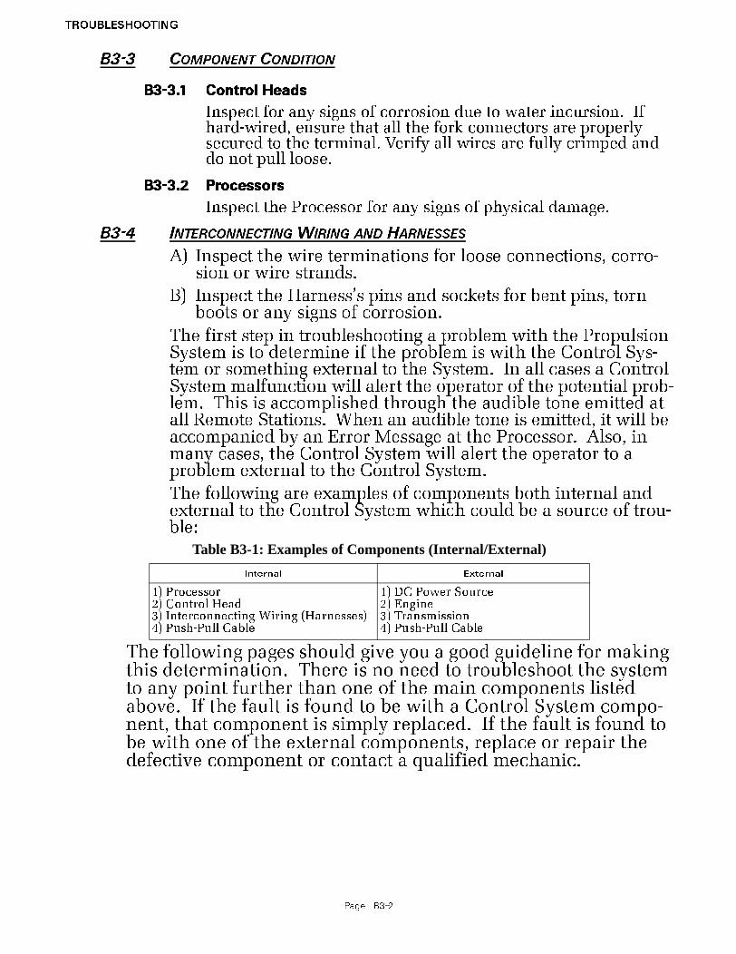
TROUBLESHOOTING
Page B3-2
B3-3 COMPONENT CONDITION
B3-3.1 Control Heads
Inspect for any signs of corrosion due to water incursion. If hard-wired, ensure that all the fork connectors are properly secured to the terminal. Verify all wires are fully crimped and do not pull loose.
B3-3.2 Processors
Inspect the Processor for any signs of physical damage.
B3-4 INTERCONNECTING WIRING AND HARNESSES
A) Inspect the wire terminations for loose connections, corro-sion or wire strands.
B) Inspect the Harness’s pins and sockets for bent pins, torn boots or any signs of corrosion.
The first step in troubleshooting a problem with the Propulsion System is to determine if the problem is with the Control Sys-tem or something external to the System. In all cases a Control System malfunction will alert the operator of the potential prob-lem. This is accomplished through the audible tone emitted at all Remote Stations. When an audible tone is emitted, it will be accompanied by an Error Message at the Processor. Also, in many cases, the Control System will alert the operator to a problem external to the Control System.
The following are examples of components both internal and external to the Control System which could be a source of trou-ble:
The following pages should give you a good guideline for making this determination. There is no need to troubleshoot the system to any point further than one of the main components listed above. If the fault is found to be with a Control System compo-nent, that component is simply replaced. If the fault is found to be with one of the external components, replace or repair the defective component or contact a qualified mechanic.
Table B3-1: Examples of Components (Internal/External)
Internal External
1) Processor2) Control Head3) Interconnecting Wiring (Harnesses)4) Push-Pull Cable
1) DC Power Source2) Engine3) Transmission4) Push-Pull Cable

TROUBLESHOOTING
Page B4-1
B4 TROUBLESHOOTING DIAGNOSTIC MENU
The Processor has built in diagnostics designed to assist the tech-nician in determining the cause of a problem. The following information is available to view at any time:
• Applied Battery Voltage
• Tachometer Sender Frequency
• Stations 1- 5 A/D’s
• Stations 1- 5 Transfer Button Status
• Servo 2 Feedback A/D’s
• Servo 1 Feedback A/D’s
• Software Revision Level
In order to access this information, follow the steps below:
Figure B4-1: Display Function Code List
Figure B4-2: Display Troubleshooting Function
Figure B4-3: Display Troubleshooting Function Blinking
Figure B4-4: Example Display of Applied Battery Voltage
Figure B4-5: Example Display of Tach Sensor Frequency
A) Locate the Display LED on the Port or Star-board Processor. The Display LED will have the Processor Part Number displayed in a run-ning pattern moving from left to right while the program is running in Normal Operation.
B) Depress the Up or Down Push Button to acti-vate the Function Code List. The characters A001 will be shown on the Display like Figure B4-1:
C) Depress the Up or Down Push Button repeat-edly until H000 is displayed like Figure B4-2:.
D) Depress and hold the Left and Right Push But-tons simultaneously until the H0 begins to blink. (Figure B4-3:) Release the Push Buttons; the applied battery voltage will now be dis-played:•The displayed value is in “real time” and pro-
vides a rough estimate of the DC voltage applied to the Processor. The reading is accurate to within 0.50 DC. Refer to Figure B4-4:
E) In addition to the applied battery voltage, scrolling through the Diagnostics Menu by pressing the Up or Down Push Button can also show the Tachometer Sender Frequency (Fig-ure B4-5:):•The information shown is the actual frequency
outputted by the Tachometer Sender. This sig-nal is utilized in “Closed Loop” Synchronization or “Closed Loop” Troll (future) systems
Function Code is Blinking
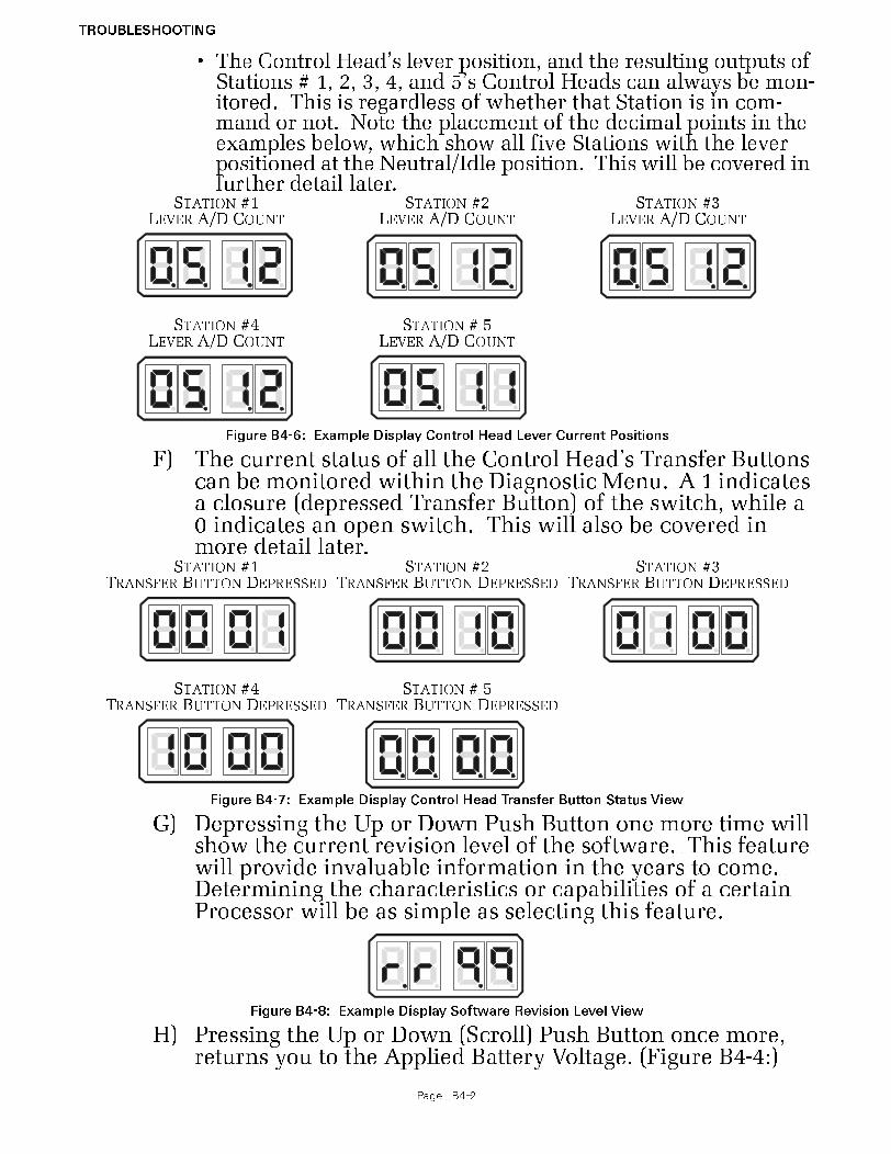
TROUBLESHOOTING
Page B4-2
• The Control Head’s lever position, and the resulting outputs of Stations # 1, 2, 3, 4, and 5’s Control Heads can always be mon-itored. This is regardless of whether that Station is in com-mand or not. Note the placement of the decimal points in the examples below, which show all five Stations with the lever positioned at the Neutral/Idle position. This will be covered in further detail later.
F) The current status of all the Control Head’s Transfer Buttons can be monitored within the Diagnostic Menu. A 1 indicates a closure (depressed Transfer Button) of the switch, while a 0 indicates an open switch. This will also be covered in more detail later.
G) Depressing the Up or Down Push Button one more time will show the current revision level of the software. This feature will provide invaluable information in the years to come. Determining the characteristics or capabilities of a certain Processor will be as simple as selecting this feature.
H) Pressing the Up or Down (Scroll) Push Button once more, returns you to the Applied Battery Voltage. (Figure B4-4:)
STATION #1LEVER A/D COUNT
STATION #4LEVER A/D COUNT
STATION #2LEVER A/D COUNT
STATION # 5LEVER A/D COUNT
STATION #3LEVER A/D COUNT
Figure B4-6: Example Display Control Head Lever Current Positions
STATION #1TRANSFER BUTTON DEPRESSED
STATION #4TRANSFER BUTTON DEPRESSED
STATION #2TRANSFER BUTTON DEPRESSED
STATION # 5TRANSFER BUTTON DEPRESSED
STATION #3TRANSFER BUTTON DEPRESSED
Figure B4-7: Example Display Control Head Transfer Button Status View
Figure B4-8: Example Display Software Revision Level View

TROUBLESHOOTING
Page B4-3
I) The Diagnostic Menu can be exited two ways:• Do not touch any Push Buttons for 5 minutes. The system will
automatically exit.
• Depress the Left Push Button until H000 appears. You may now scroll through the Set Up Menu.

TROUBLESHOOTING
Page B5-1
B5 TROUBLESHOOTING AUDIBLE TONES
As mentioned previously, there are various tones emitted from the Control Head if an error were to occur.
B5-1 BASIC CONTROL SYSTEM TONES
These basic tones are as follows:
B5-1.1 Slow Repetitive Tone
The Slow Repetitive Tone, also referred to as the “Initializa-tion Tone” is the tone you hear at all Remote Stations when power is initially applied to the control system. When this tone is heard, you know for a fact that the following are true:
• Power has just been applied to the system.
• The Software Program is running normally.
• The Processor is commanding the throttle to Idle.
• The Processor is commanding the clutch to Neutral.
This is a normal tone when power has first been applied to the Processor and no Control Head has taken command. However, the tone may also be an indication of a problem, if during normal operation the engine’s throttle drops to Idle, followed by the clutch to Neutral, the Control Head’s red LED goes out and a slow repetitive tone is heard at all remote stations. This indicates that the voltage at the Pro-cessor has momentarily dropped below 8 VDC and then returned to a normal operational level. This could be due to:
• Loose battery power cable connection.
• Under-charged or defective battery.
• Voltage drop due to current flow.
In order to pinpoint the exact cause of the low voltage at the Processor, perform the following checks:
A) Check the Display on the Processor for Error Mes-sages. Error Message 57 may appear indicating Under Voltage. One or more of Error Messages 43 through 54 may also be displayed. This is due to the momentary loss of serial communication between the two Processors. Take note that the Under Voltage error is not only dependent on low voltage, it is also dependent on the duration of the low voltage. The possibility exists that an error message would not be displayed if the duration of the low voltage was short enough. However, the other symptoms mentioned above still occur.
B) In either case, follow the procedure listed under Diagnostic Menu (Section B4, page B4-1) until the
Figure B5-1: Slow Repetitive Tone
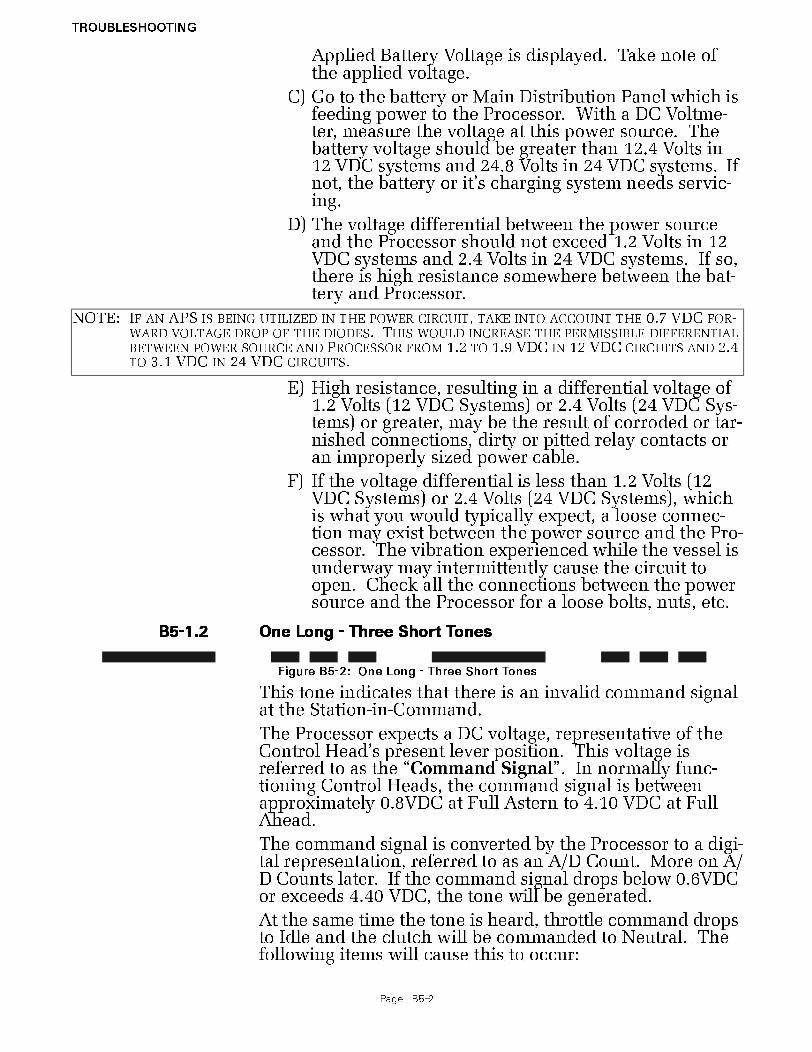
TROUBLESHOOTING
Page B5-2
Applied Battery Voltage is displayed. Take note of the applied voltage.
C) Go to the battery or Main Distribution Panel which is feeding power to the Processor. With a DC Voltme-ter, measure the voltage at this power source. The battery voltage should be greater than 12.4 Volts in 12 VDC systems and 24.8 Volts in 24 VDC systems. If not, the battery or it’s charging system needs servic-ing.
D) The voltage differential between the power source and the Processor should not exceed 1.2 Volts in 12 VDC systems and 2.4 Volts in 24 VDC systems. If so, there is high resistance somewhere between the bat-tery and Processor.
E) High resistance, resulting in a differential voltage of 1.2 Volts (12 VDC Systems) or 2.4 Volts (24 VDC Sys-tems) or greater, may be the result of corroded or tar-nished connections, dirty or pitted relay contacts or an improperly sized power cable.
F) If the voltage differential is less than 1.2 Volts (12 VDC Systems) or 2.4 Volts (24 VDC Systems), which is what you would typically expect, a loose connec-tion may exist between the power source and the Pro-cessor. The vibration experienced while the vessel is underway may intermittently cause the circuit to open. Check all the connections between the power source and the Processor for a loose bolts, nuts, etc.
B5-1.2 One Long - Three Short Tones
This tone indicates that there is an invalid command signal at the Station-in-Command.
The Processor expects a DC voltage, representative of the Control Head’s present lever position. This voltage is referred to as the “Command Signal”. In normally func-tioning Control Heads, the command signal is between approximately 0.8VDC at Full Astern to 4.10 VDC at Full Ahead.
The command signal is converted by the Processor to a digi-tal representation, referred to as an A/D Count. More on A/D Counts later. If the command signal drops below 0.6VDC or exceeds 4.40 VDC, the tone will be generated.
At the same time the tone is heard, throttle command drops to Idle and the clutch will be commanded to Neutral. The following items will cause this to occur:
NOTE: IF AN APS IS BEING UTILIZED IN THE POWER CIRCUIT, TAKE INTO ACCOUNT THE 0.7 VDC FOR-WARD VOLTAGE DROP OF THE DIODES. THIS WOULD INCREASE THE PERMISSIBLE DIFFERENTIAL BETWEEN POWER SOURCE AND PROCESSOR FROM 1.2 TO 1.9 VDC IN 12 VDC CIRCUITS AND 2.4 TO 3.1 VDC IN 24 VDC CIRCUITS.
Figure B5-2: One Long - Three Short Tones

TROUBLESHOOTING
Page B5-3
• An open or high resistance connection between the Con-trol Head and Processor.
• Out of calibration Control Head.
• A defective Control Head.
• A defective A/D Converter in the Processor.
The exact cause of the malfunction can be found as follows:
A) Check the Processor’s Display for error messages. Most likely, one of error messages 13 thru 32 will be shown. The exact number shown depends on which remote station is experiencing the problem and whether the command signal was too high or too low.
B) Enter the Diagnostic Menu as outlined in Section B4, page B4-1.
C) Depress the Up or Down (Scroll) Push Button until the appropriate Remote Station is displayed.
• The Remote Station are identified by the position of the decimal points.
• Station 1 has no decimal point after the first digit to the far right. The remaining three digits all have decimal points.
• If the digit to the far left had no decimal point following it, but the remaining three do, this would represent Sta-tion 4.
D) The examples in Figure B5-3: are shown with no Control Heads connected to any Remote Stations. When a Control Head is connected, the appropriate A/D (Analog/Digital) value for the present position of
STATION 1
STATION 4
STATION 2
STATION 5
STATION 3
Figure B5-3: Display Examples of Remote Stations

TROUBLESHOOTING
Page B5-4
the Control Head’s lever will be shown, as in the examples below:
E) An A/D value of 910 or greater will generate an Error Code. The code will be 13 to 22 (Control Head # Faulted High), depending on which Station has the high Command Signal.
• If the A/D value is greater than 910, but less than 990, one of the following may be the cause:
1. The Control Head’s potentiometer is out of calibra-tion.
2. The potentiometer is defective.In either case, it is recommended that the Control Head is replaced.
• If the A/D value is 995 or higher, most likely the potenti-ometer’s ground has been lost.
• Right hand Control Heads have a jumper between pins 3 and 5 if a Harness is used. This jumper provides the potentiometers ground.
• Left hand Control heads have a jumper between pins 3 and 7 is a Harness is used. This jumper provides the potentiometers ground.
• The potentiometer ground connection for Control Heads which are hard-wired to the Processor is through the yellow wire (pin 5 on right hand and pin 7 on left hand).
F) If the A/D value is 100 or less, one of Error Codes 23- 32 (Control Head # Faulted Low) will be shown.
• If the A/D value is less than 100, but greater than 75, the following may be the cause:
1. The Control Head’s potentiometer is out of calibra-tion.
2. The potentiometer is defective.
3. A high resistance connection exists on pin 6 (green wire) between the Control Head and Processor.
• If the A/D value is less than 75:
1. There is an open wire between pin 6 (green wire) of the Control Head and the Processor.
STATION 1 (NEUTRAL COMMANDED)
STATION 4 (NO CONTROL HEAD CONNECTED)
STATION 2 (FULL AHEAD COMMANDED)
STATION 5(NEUTRAL COMMANDED)
STATION 3 (FULL ASTERN COMMANDED)
Figure B5-4: Display Examples of Remote Stations A/D Value

TROUBLESHOOTING
Page B5-5
2. There is an open wire between pin 7 (blue wire) of a right hand Control Head and the Processor.
3. There is an open wire between pin 5 (blue wire) of a left hand Control Head and pin 7 (blue wire) of the Processor.
B5-1.3 Steady Tone
The Steady Tone is an indication to the operator that some-thing has gone wrong within the Control System. The Steady Tone will typically be accompanied by an Error Mes-sage on the Processor’s Display. If the tone is heard, the Processor’s Display must be referred to in order to further diagnosis the problem.
The Transfer Button is shorted - Tone will cease when com-mand is taken at another Station.
If the Transfer Button becomes shorted for 12 seconds or more during Normal Operation, a steady tone will be pro-duced at all Remote Stations as long as the Transfer Button remains shorted. Full System control remains. Transfer-ring to another Remote Station silences the Steady Tone. Command cannot be regained at the Station until the prob-lem is rectified.
B5-1.4 Three Second Steady Tone
This tone could indicate one of three things.
Transfer Button on the Control Head in command is stuck.
If the Processor for this System includes the use of Back-up Mode, this tone would indicate that there has been a switch closure requesting Back-up Mode.
If the Processor for this System includes Integrated Sole-noid Trolling Valve control, this tone would indi-cate that there has been a Troll Solenoid error. Refer to the Error Code displayed.
B5-1.5 Three Second Steady Tone, followed by a Slow Repetitive Tone
This tone indicates that there has been a shorted Transfer Button on power-up. Command can be gained at any other Remote Station, which silences the Slow Repetitive Tone.
Figure B5-5: Steady Tone
Figure B5-6: Three Second Tone
Figure B5-7: Three Second Tone, followed by a Slow Repetitive Tone

TROUBLESHOOTING
Page B5-6
B5-1.6 Five Seconds On, Five Seconds Off - High Repetitive Rate Tone
Loss of communication with Station Expander (SE) or the Troll Actuator (p/n 9001). This tone cannot be cleared unless all Error Codes (Active and In-Active) have been cleared.
B5-1.7 Five Second Steady Tone
Loss of Serial Communication.
B5-2 SERVO 1 CONTROL SYSTEM TONES
B5-2.1 One Long - One Short Tone
This tone indicates that the feedback signal, which repre-sents the position of the Servo 1 cross-bar, is out of the expected range.
This tone will be accompanied by Error Code 63 or 64.
• If Error Code 63 is displayed, the signal received from the feedback potentiometer is higher than expected. This is due to one of the three following reasons:
1. The orange wire (ground) between the potentiome-ter and plug are not making contact, or have a high resistance contact.
2. The potentiometer is out of calibration.
3. The potentiometer is defective.
• If Error Code 64 is displayed, the signal received from the feedback potentiometer is lower than expected. This is due to one of the following reasons:
1. The green (signal) or orange (reference voltage) wires between the potentiometer and plug are not making contact or have a high resistance contact.
2. The potentiometer is out of calibration.
3. The potentiometer is defective.
4. The Control Circuit is defective.
The Servo 1 feedback signal can be viewed within the Diag-nostic Menu. The Value displayed depends on the direction and amount of push-pull cable travel. As a general rule:
• When the Value displayed is 1023 or 0, the problem is with the wiring between the potentiometer and plug.
• If the displayed Value varies, the potentiometer is defec-tive.
Figure B5-8: Five Seconds On, Five Seconds Off - High Repetitive Rate Tone
Figure B5-9: Five Second Steady Tone
Figure B5-10: One Long - One Short Tone
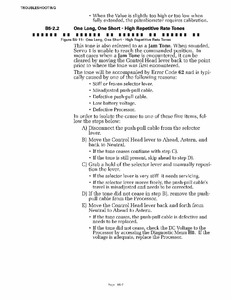
TROUBLESHOOTING
Page B5-7
• When the Value is slightly too high or too low when fully extended, the potentiometer requires calibration.
B5-2.2 One Long, One Short - High Repetitive Rate Tones
This tone is also referred to as a Jam Tone. When sounded, Servo 1 is unable to reach the commanded position. In most cases when a Jam Tone is encountered, it can be cleared by moving the Control Head lever back to the point prior to where the tone was first encountered.
The tone will be accompanied by Error Code 62 and is typi-cally caused by one of the following reasons:
• Stiff or frozen selector lever.
• Misadjusted push-pull cable.
• Defective push-pull cable.
• Low battery voltage.
• Defective Processor.
In order to isolate the cause to one of these five items, fol-low the steps below:
A) Disconnect the push-pull cable from the selector lever.
B) Move the Control Head lever to Ahead, Astern, and back to Neutral.
• If the tone ceases continue with step C).
• If the tone is still present, skip ahead to step D).
C) Grab a hold of the selector lever and manually reposi-tion the lever.
• If the selector lever is very stiff it needs servicing.
• If the selector lever moves freely, the push-pull cable’s travel is misadjusted and needs to be corrected.
D) If the tone did not cease in step B), remove the push-pull cable from the Processor.
E) Move the Control Head lever back and forth from Neutral to Ahead to Astern.
• If the tone ceases, the push-pull cable is defective and needs to be replaced.
• If the tone did not cease, check the DC Voltage to the Processor by accessing the Diagnostic Menu H0. If the voltage is adequate, replace the Processor.
Figure B5-11: One Long, One Short - High Repetitive Rate Tones

TROUBLESHOOTING
Page B5-8
B5-3 SERVO 2 CONTROL SYSTEM TONES
B5-3.1 One Long - Two Short Tones
This tone indicates that the feedback signal, which repre-sents the position of the Servo 2 cross-bar, is out of expected range.
This tone will be accompanied by Error Code 66 or 67.
• If Error Code 66 is displayed, the signal received from the feedback potentiometer is higher than expected. This is due to one of the three following reasons:
1. The orange wire (ground) between the potentiome-ter and plug are not making contact, or have a high resistance contact.
2. The potentiometer is out of calibration.
3. The potentiometer is defective.
• If Error Code 67 is displayed, the signal received from the feedback potentiometer is lower than expected. This is due to one of the following reasons:
1. The green (signal) or orange (reference voltage) wires between the potentiometer and plug are not making contact or have a high resistance contact.
2. The potentiometer is out of calibration.
3. The potentiometer is defective.
4. The Control Circuit is defective.
The Servo 2 feedback signal can be viewed within the Diag-nostic Menu. The Value displayed depends on the direction and amount of push-pull cable travel. As a general rule:
• When the Value displayed is 1023 or 0, the problem is with the wiring between the potentiometer and plug.
• If the displayed Value varies, the potentiometer is defec-tive.
• When the Value is slightly too high or too low when fully extended, the potentiometer requires calibration.
B5-3.2 One Long, Two Short - High Repetitive Rate Tones
This tone is also referred to as a Jam Tone. When sounded, Servo 2 is unable to reach the commanded position. In most cases when a Jam Tone is encountered, it can be cleared by moving the Control Head lever back to the point prior to where the tone was first encountered.
The tone will be accompanied by Error Code 65 and is typi-cally caused by one of the following reasons:
• Stiff or frozen selector lever.
• Misadjusted push-pull cable.
Figure B5-12: One Long - Two Short Tones
Figure B5-13: One Long, Two Short - High Repetitive Rate Tones
TROUBLESHOOTING
Page B5-9
• Defective push-pull cable.
• Low battery voltage.
• Defective Processor.
In order to isolate the cause to one of these five items, fol-low the steps below:
A) Turn the power ON to the Processor.
• If the tone is not present continue with step C)
• If the tone is present, check the DC voltage to the Pro-cessor by accessing the Diagnostic Menu H0. If the voltage is adequate continue with step B.
B) Disconnect the push-pull cable from the selector lever.
• If the tone is still present after cycling power, replace the Processor.
• If the tone is no longer present, continue with step C)
C) If disconnected, reconnect the push-pull cable.
D) Depress the Transfer Button while moving the Con-trol Head lever to the Ahead detent.
E) Release the transfer button and continue to move the Control Head lever through the speed range.
• If the tone does not sound until the Control Head lever is close to full throttle, Function Code E3 Throttle Maxi-mum is misadjusted.
• If the tone sounds earlier than full throttle, continue with step F).
F) Disconnect the push-pull cable from the selector lever.
G) Manually reposition the selector lever (Idle to Full).
• If the selector lever is very stiff it needs to be serviced.
• If the selector lever moves freely, the push-pull cable is defective and needs replacing.
TROUBLESHOOTING
Page B6-1
B6 TROUBLESHOOTING STATION TRANSFER
In order to transfer command from one Remote Station to another, the following must occur:
• There must be a valid “Command Signal” at the Station being transferred to.
• The “Command Signal” must indicate that the Control Head’s lever(s) is at the Neutral/Idle position.
• The Transfer Button must be depressed which takes the “Sta-tion Select” signal from 5.00 VDC to 0.00 VDC.
If a transfer from one Remote Station to another is requested, but does not take place; the items required for successful transfer can be tested as follows:
B6-1 COMMAND SIGNAL
The Command Signal is a DC voltage which varies in relation-ship to the Control Head’s lever position.
The Processor provides each Control Head 5.00 +/- 0.20VDC, which is referred to as the “Reference Voltage”.
The Reference Voltage is applied to a 5K Ohm Potentiometer in the Control Head.
The potentiometer’s “Wiper” taps off a portion of the Reference Voltage and sends it back to the Processor.
The amount of DC voltage which is tapped off, is dependant on the position of the Control Head’s lever.
When the lever is fully Astern, a small portion of the Reference Voltage is tapped off by the wiper, and therefore, the voltage is at its lowest point (approximately 0.80 VDC).
When the lever is positioned fully Ahead, a larger portion is tapped off and the voltage is at its highest point (approximately 4.10 VDC).
B6-2 A TO D COUNTS
Since all the calculations within the control system are per-formed digitally, these DC voltages are expressed as and con-verted to a digital representation.
• The “Reference Voltage” (approximately 5.00 VDC) by which all analog inputs are based, is represented as 1023 A/D (Ana-log to Digital) Counts.
• This allows for the possibility of a 1024 possible positions when 0 is included in the count.
• The value of the Command Voltage with the lever at the Neu-tral/Idle position is 49- 51% of the Reference Voltage when measured at the Station terminal block. The actual value read by the Processor is 2% below that value or 47% to 49% of 1023 A/D Counts (485- 505 A/D).

TROUBLESHOOTING
Page B6-2
• The Command Signal at Full Ahead is 82- 84% of the Refer-ence Voltage when measured at the Station terminal block. The actual value read by the Processor is 2% below that value or 80- 82% of 1023 A/D Counts (821- 841 A/D).
• The Command Signal at Full Astern is 17 - 19% of the Refer-ence Voltage when measured at the Station terminal block. The actual value read by the Processor is 2% below that value or 15- 17% of 1023 A/D Counts (153- 173 A/D).
• Since the Command Signal is based on a percentage of the Reference Voltage, the distance of the Control Head from the Processor has no impact on the performance of the system.
• The amount of voltage drop, due to current flow, is the same for both the Reference and Command Voltages.
• The relationship between the Reference and Command Volt-ages when thought of as a percentage, will remain the same regardless of distance. For instance, here are two examples.
Example 1
Reference Voltage 5.00 VDC1023 A/D Counts
Command Voltage2.45 VDC501 A/D Counts
Example 2
Reference Voltage4.80 VDC1023 A/D Counts
Command Voltage2.35 VDC501 A/D Counts
As you can see by the examples, even though the Command Voltages are different between Examples 1 and 2, the resulting A/D counts, are the same because of the different Reference Voltages. This would result in the Processor commanding the identical outputs (Clutch & Throttle) in both cases.
A) The A/D count for a specific Control Head’s lever can be seen on the Processor’s Display by following the steps outlined in Section B4, page B4-1.
B) Once the appropriate remote station is reached, ensure that the displayed A/D Count represents the Neutral/Idle position (485- 505 A/D counts). Command will not be accepted unless the Control Head’s lever is at the Neu-tral/Idle position.
The following table shows the appropriate A/D Counts for vari-ous Control Head lever positions:
NOTE: THE A/D VALUES LISTED FOR FULL AHEAD AND FULL ASTERN REPRESENT THE POINT WHERE MAXIMUM THROTTLE IS REACHED. THE A/D COUNT WHEN THE CONTROL HEAD LEVER IS PHYS-ICALLY AT IT’S MAXIMUM POINT WILL BE HIGHER, BUT MAY NOT EXCEED THE OUT-OF-RANGE VAL-UES LISTED IN TABLE B6-1:, PAGE B6-2.
Table B6-1: Control Head Lever A/D Counts
Control Head Lever Position A/D Count
Lever Out of Range Low 100
Full Astern 153 - 173
Neutral/ Idle 485 - 505

TROUBLESHOOTING
Page B6-3
B6-3 REMOTE STATION SELECT
The second required item for taking command is “Station Select” or depressing of the Transfer Button.
• The Transfer Button can be tested by entering the Diagnos-tic Menu H0.
Control Head Lever Position A/D Count
Ahead Shift Point 537
Full Ahead 821 - 841
Lever Out of Range High 910
Figure B6-1: Display Station A/D’s No Station Transfer Button Depressed
Figure B6-2: Example Display Station A/D’s Transfer Button Depressed for Stations 1 - 4
Figure B6-3: Display Station A/D/s Transfer Button Depressed for Station 5
A) Depress the Up or Down (scroll) Push Button until four zeroes are displayed without decimal points as shown in Fig-ure B6-1:.
B) For Stations 1 - 4 when the Transfer Button is depressed, the 0 which repre-sents that remote station, will change to a 1 as shown in Figure B6-2:. For Station 5 when the Transfer Button is depressed, all four decimal points will light as shown in Figure B6-3:
• Whenever command cannot be gained at a particular remote station, the Sta-tion Select and Command Signals are the first to be investigated. If either the Command Signal is out of range or the Station Select is inoperable, com-mand will not be accepted at that remote station.
Table B6-1: Control Head Lever A/D Counts

TROUBLESHOOTING
Page B7-1
B7 TROUBLESHOOTING STUCK TRANSFER BUTTON
The Transfer Button is a normally open, momentary switch. The only time the switch should close is when it is depressed to take command or when entering or departing various other func-tions. In the event that the Transfer Button became stuck in the closed position, the following will occur:
• The Transfer Button would have to be closed for 15 seconds or more.
• The throttle and clutch are not affected.
• A solid tone is heard from all remote stations, until the button’s contact opens or transfer to another remote station has taken place.
If a Control Head that is not in command has a stuck transfer button, the following will happen:
• If Control Head levers are positioned at Neutral/Idle, a solid tone is heard from all remote stations.
• If Control Head levers are positioned other than Neutral/Idle, a three (3) second tone is heard from all remote stations.
• Error Code 33 - 42, depending on which remote station, will be shown on the Processor Display.
• Command can be taken at any other operational remote sta-tion.
• After one (1) second command can be regained at the remote station with the stuck button as long as the problem has been corrected by depressing the transfer button.
If a stuck Transfer Button is suspected, this can be verified by looking at the Station Select status (1 or 0) as outlined in Section B6-3, page B6-3.
• An Error Code 33 - 42 will be shown on the Display, depending on which Station is experiencing the problem.

TROUBLESHOOTING
Page B8-1
B8 ERROR CODES
As stated previously, if a problem with the Control System is detected, the Processor is programmed to display numerous Error Codes to aid in the isolation of the cause. The following tables list these Error Codes, along with a brief description.
B8-4 BASIC CONTROL SYSTEM ERROR CODES
Table B8-2: Basic Control System Error Codes
Error No.
Title Description
13 Station No.1 Faulted High
Station No.1 Control Head’s lever position is out of range. The input appears to be too high.
14 Station No.2 Faulted High
Station No.2 Control Head’s lever position is out of range. The input appears to be too high.
15 Station No.3 Faulted High
Station No.3 Control Head’s lever position is out of range. The input appears to be too high.
16 Station No.4 Faulted High
Station No.4 Control Head’s lever position is out of range. The input appears to be too high.
17 Station No.5 Faulted High
Station No.5 Control Head’s lever position is out of range. The input appears to be too high.
18 Station No.6 Faulted High
Station No.6 Control Head’s lever position is out of range. The input appears to be too high.
19 Station No.7 Faulted High
Station No.7 Control Head’s lever position is out of range. The input appears to be too high.
20 Station No.8 Faulted High
Station No.8 Control Head’s lever position is out of range. The input appears to be too high.
21 Station No.9 Faulted High
Station No.9 Control Head’s lever position is out of range. The input appears to be too high.
22 Station No.10 Faulted High
Station No.10 Control Head’s lever position is out of range. The input appears to be too high.
23 Station No.1Faulted Low
Station No.1 Control Head’s lever position is out of range. The input appears to be too low.
24 Station No.2 Faulted Low
Station No.2 Control Head’s lever position is out of range. The input appears to be too low.
25 Station No.3 Faulted Low
Station No.3 Control Head’s lever position is out of range. The input appears to be too low.
26 Station No.4 Faulted Low
Station No.4 Control Head’s lever position is out of range. The input appears to be too low.
27 Station No.5 Faulted Low
Station No.5 Control Head’s lever position is out of range. The input appears to be too low.
28 Station No.6 Faulted Low
Station No.6 Control Head’s lever position is out of range. The input appears to be too low.
29 Station No.7 Faulted Low
Station No.7 Control Head’s lever position is out of range. The input appears to be too low.
30 Station No.8 Faulted Low
Station No.8 Control Head’s lever position is out of range. The input appears to be too low.
31 Station No.9 Faulted Low
Station No.9 Control Head’s lever position is out of range. The input appears to be too low.
32 Station No.10 Faulted Low
Station No.10 Control Head’s lever position is out of range. The input appears to be too low.
33 Station No.1 Button Stuck Closed
Station No.1 Control Head’s Transfer Button has either been closed too long or has been closed since power-up.
34 Station No.2 Button Stuck Closed
Station No.2 Control Head’s Transfer Button has either been closed too long or has been closed since power-up.
35 Station No.3 Button Stuck Closed
Station No.3 Control Head’s Transfer Button has either been closed too long or has been closed since power-up.
36 Station No.4 Button Stuck Closed
Station No.4 Control Head’s Transfer Button has either been closed too long or has been closed since power-up.
37 Station No.5 Button Stuck Closed
Station No.5 Control Head’s Transfer Button has either been closed too long or has been closed since power-up.
38 Station No.6 Button Stuck Closed
Station No.6 Control Head’s Transfer Button has either been closed too long or has been closed since power-up.

TROUBLESHOOTING
Page B8-2
B8-1 SERVO 1 ERROR CODES
B8-2 SERVO 2 ERROR CODES
B8-3
39 Station No.7 Button Stuck Closed
Station No.7 Control Head’s Transfer Button has either been closed too long or has been closed since power-up.
40 Station No.8 Button Stuck Closed
Station No.8 Control Head’s Transfer Button has either been closed too long or has been closed since power-up.
41 Station No.9 Button Stuck Closed
Station No.9 Control Head’s Transfer Button has either been closed too long or has been closed since power-up.
42 Station No.10 Button Stuck Closed
Station No.10 Control Head’s Transfer Button has either been closed too long or has been closed since power-up.
43 CAN Communication Stuffing Error
The Control-Area-Network protocol has detected an error in communication with other devices on the network. The error type is a stuffing error.
44 CAN Communication Form Error
The Control-Area-Network protocol has detected an error in communication with other devices on the network. The error type is a form error.
45 CAN Communication Acknowledge Error
The Control-Area-Network protocol has detected an error in communication with other devices on the network. The error type is an acknowledge error.
46 CAN Communication Bit 1 Error
The Control-Area-Network protocol has detected an error in communication with other devices on the network. The error type is a Bit 1 error.
47 CAN Communication Bit 0 Error
The Control-Area-Network protocol has detected an error in communication with other devices on the network. The error type is a Bit 0 error.
48 CAN Communication CRC Error
The Control-Area-Network protocol has detected an error in communication with other devices on the network. The error type is a CRC error.
49 CAN Communication Bus Error
The Control-Area-Network protocol has detected an error in communication with other devices on the network. The error type is a Bus failure error. The error cannot be recovered from without cycling power to the Processor.
50 Comm. Error Time-out System 1
Communication with System 1 has been too long without a Refresh message.
51 Comm. Error Time-out System 2
Communication with System 1 has been too long without a Refresh message.
52 Comm. Error Time-out System 3
Communication with System 1 has been too long without a Refresh message.
53 Comm. Error Time-out System 4
Communication with System 1 has been too long without a Refresh message.
54 Comm. Error Time-out System 5
Communication with System 1 has been too long without a Refresh message.
55 SE Communication Error Communication with the Station Expander has been too long without a Refresh message.
56 High Battery Voltage Fault The applied battery voltage is 30VDC or higher for at least two seconds.
57 Low Battery Voltage Fault The applied battery voltage is 10VDC or lower for at least two seconds.
58 Reset Due to Software Watchdog
The system has had an unexpected Reset, due to a software/ hardware fault.
59 Reset Due to Software Fault The system has had an unexpected Reset, due to a software fault.
60 Reset Due to Hardware Watchdog
The system has had an unexpected Reset, due to a software/ hardware fault.
61 Oscillator Watchdog The system’s Oscillator has had an unexpected fault.
Table B8-3: Servo 1 Error Codes
Error No.
Title Description
62 Servo 1 Jam Servo one is unable to make any progress toward its commanded position.
63 Servo 1Feedback High Servo one’s position feedback voltage is higher than the acceptable range.
64 Servo 1 Feedback Low Servo one’s position feedback voltage is lower than the acceptable range.
Table B8-4: Servo 2 Error Codes
Error No.
Title Description
65 Servo 2 Jam Servo two is unable to make any progress toward its commanded position.
66 Servo 2 Feedback High Servo two’s position feedback voltage is higher than the acceptable range.
67 Servo 2 Feedback Low Servo two’s position feedback voltage is lower than the acceptable range.
Table B8-2: Basic Control System Error Codes
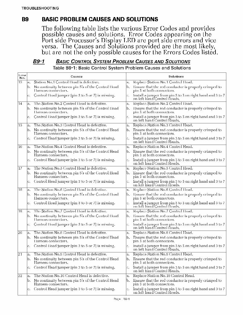
TROUBLESHOOTING
Page B9-1
B9 BASIC PROBLEM CAUSES AND SOLUTIONS
The following table lists the various Error Codes and provides possible causes and solutions. Error Codes appearing on the Port side Processor’s Display LED are port side errors and vice versa. The Causes and Solutions provided are the most likely, but are not the only possible causes for the Errors Codes listed.
B9-1 BASIC CONTROL SYSTEM PROBLEM CAUSES AND SOLUTIONS
Table B9-1: Basic Control System Problem Causes and Solutions
Error
No.Causes Solutions
13 a. Station No.1 Control Head is defective. a. Replace Station No.1 Control Head.
b. No continuity between pin 5’s of the Control Head Harness connectors.
b. Ensure that the red conductor is properly crimped to pin 5 at both connectors.
c. Control Head jumper (pin 3 to 5 or 7) is missing. c. Install a jumper from pin 3 to 5 on right hand and 3 to 7 on left hand Control Heads.
14 a. The Station No.2 Control Head is defective. a. Replace Station No.2 Control Head.
b. No continuity between pin 5’s of the Control Head Harness connectors.
b. Ensure that the red conductor is properly crimped to pin 5 at both connectors.
c. Control Head jumper (pin 3 to 5 or 7) is missing. c. Install a jumper from pin 3 to 5 on right hand and 3 to 7 on left hand Control Heads.
15 a. The Station No.3 Control Head is defective. a. Replace Station No.3 Control Head.
b. No continuity between pin 5’s of the Control Head Harness connectors.
b. Ensure that the red conductor is properly crimped to pin 5 at both connectors.
c. Control Head jumper (pin 3 to 5 or 7) is missing. c. Install a jumper from pin 3 to 5 on right hand and 3 to 7 on left hand Control Heads.
16 a. The Station No.4 Control Head is defective. a. Replace Station No.4 Control Head.
b. No continuity between pin 5’s of the Control Head Harness connectors.
b. Ensure that the red conductor is properly crimped to pin 5 at both connectors.
c. Control Head jumper (pin 3 to 5 or 7) is missing. c. Install a jumper from pin 3 to 5 on right hand and 3 to 7 on left hand Control Heads.
17 a. The Station No.5 Control Head is defective. a. Replace Station No.5 Control Head.
b. No continuity between pin 5’s of the Control Head Harness connectors.
b. Ensure that the red conductor is properly crimped to pin 5 at both connectors.
c. Control Head jumper (pin 3 to 5 or 7) is missing. c. Install a jumper from pin 3 to 5 on right hand and 3 to 7 on left hand Control Heads.
18 a. The Station No.6 Control Head is defective. a. Replace Station No.6 Control Head.
b. No continuity between pin 5’s of the Control Head Harness connectors.
b. Ensure that the red conductor is properly crimped to pin 5 at both connectors.
c. Control Head jumper (pin 3 to 5 or 7) is missing. c. Install a jumper from pin 3 to 5 on right hand and 3 to 7 on left hand Control Heads.
19 a. The Station No.7 Control Head is defective. a. Replace Station No.7 Control Head.
b. No continuity between pin 5’s of the Control Head Harness connectors.
b. Ensure that the red conductor is properly crimped to pin 5 at both connectors.
c. Control Head jumper (pin 3 to 5 or 7) is missing. c. Install a jumper from pin 3 to 5 on right hand and 3 to 7 on left hand Control Heads.
20 a. The Station No.8 Control Head is defective. a. Replace Station No.8 Control Head.
b. No continuity between pin 5’s of the Control Head Harness connectors.
b. Ensure that the red conductor is properly crimped to pin 5 at both connectors.
c. Control Head jumper (pin 3 to 5 or 7) is missing. c. Install a jumper from pin 3 to 5 on right hand and 3 to 7 on left hand Control Heads.
21 a. The Station No.9 Control Head is defective. a. Replace Station No.9 Control Head.
b. No continuity between pin 5’s of the Control Head Harness connectors.
b. Ensure that the red conductor is properly crimped to pin 5 at both connectors.
c. Control Head jumper (pin 3 to 5 or 7) is missing. c. Install a jumper from pin 3 to 5 on right hand and 3 to 7 on left hand Control Heads.
22 a. The Station No.10 Control Head is defective. a. Replace Station No.10 Control Head.
b. No continuity between pin 5’s of the Control Head Harness connectors.
b. Ensure that the red conductor is properly crimped to pin 5 at both connectors.
c. Control Head jumper (pin 3 to 5 or 7) is missing. c. Install a jumper from pin 3 to 5 on right hand and 3 to 7 on left hand Control Heads.

TROUBLESHOOTING
Page B9-2
Error
No.Causes Solutions
23 a. The Station No.1 Control Head is defective. a. Replace Station No.1 Control Head.
b. No continuity between pin 6’s of the Control Head Harness connectors.
b. Ensure that the green conductor is properly crimped to pin 6 at both connectors and there is continuity.
c. No continuity between pin 7’s of the Control Head Harness connectors.
c. Ensure that the blue conductor is properly crimped to pin 7 at both connectors and there is continuity.
24 a. The Station No.2 Control Head is defective. a. Replace Station No.2 Control Head.
b. No continuity between pin 6’s of the Control Head Harness connectors.
b. Ensure that the green conductor is properly crimped to pin 6 at both connectors and there is continuity.
c. No continuity between pin 7’s of the Control Head Harness connectors.
c. Ensure that the blue conductor is properly crimped to pin 7 at both connectors and there is continuity.
25 a. The Station No.3 Control Head is defective. a. Replace Station No.3 Control Head.
b. No continuity between pin 6’s of the Control Head Harness connectors.
b. Ensure that the green conductor is properly crimped to pin 6 at both connectors and there is continuity.
c. No continuity between pin 7’s of the Control Head Harness connectors.
c. Ensure that the blue conductor is properly crimped to pin 7 at both connectors and there is continuity.
26 a. The Station No.4 Control Head is defective. a. Replace Station No.4 Control Head.
b. No continuity between pin 6’s of the Control Head Harness connectors.
b. Ensure that the green conductor is properly crimped to pin 6 at both connectors and there is continuity.
c. No continuity between pin 7’s of the Control Head Harness connectors.
c. Ensure that the blue conductor is properly crimped to pin 7 at both connectors and there is continuity.
27 a. The Station No.5 Control Head is defective. a. Replace Station No.5 Control Head.
b. No continuity between pin 6’s of the Control Head Harness connectors.
b. Ensure that the green conductor is properly crimped to pin 6 at both connectors and there is continuity.
c. No continuity between pin 7’s of the Control Head Harness connectors.
c. Ensure that the blue conductor is properly crimped to pin 7 at both connectors and there is continuity.
28 a. The Station No.6 Control Head is defective. a. Replace Station No.6 Control Head.
b. No continuity between pin 6’s of the Control Head Harness connectors.
b. Ensure that the green conductor is properly crimped to pin 6 at both connectors and there is continuity.
c. No continuity between pin 7’s of the Control Head Harness connectors.
c. Ensure that the blue conductor is properly crimped to pin 7 at both connectors and there is continuity.
29 a. The Station No.7 Control Head is defective. a. Replace Station No.7 Control Head.
b. No continuity between pin 6’s of the Control Head Harness connectors.
b. Ensure that the green conductor is properly crimped to pin 6 at both connectors and there is continuity.
c. No continuity between pin 7’s of the Control Head Harness connectors.
c. Ensure that the blue conductor is properly crimped to pin 7 at both connectors and there is continuity.
30 a. The Station No.8 Control Head is defective. a. Replace Station No.8 Control Head.
b. No continuity between pin 6’s of the Control Head Harness connectors.
b. Ensure that the green conductor is properly crimped to pin 6 at both connectors and there is continuity.
c. No continuity between pin 7’s of the Control Head Harness connectors.
c. Ensure that the blue conductor is properly crimped to pin 7 at both connectors and there is continuity.
31 a. The Station No.9 Control Head is defective. a. Replace Station No.9 Control Head.
b. No continuity between pin 6’s of the Control Head Harness connectors.
b. Ensure that the green conductor is properly crimped to pin 6 at both connectors and there is continuity.
c. No continuity between pin 7’s of the Control Head Harness connectors.
c. Ensure that the blue conductor is properly crimped to pin 7 at both connectors and there is continuity.
32 a. The Station No.10 Control Head is defective. a. Replace Station No.10 Control Head.
b. No continuity between pin 6’s of the Control Head Harness connectors.
b. Ensure that the green conductor is properly crimped to pin 6 at both connectors and there is continuity.
c. No continuity between pin 7’s of the Control Head Harness connectors.
c. Ensure that the blue conductor is properly crimped to pin 7 at both connectors and there is continuity.
33 a. The Station No.1 transfer button was held down for 15 seconds or longer
a. Clear the Error Code from memory
b. The Station No.1 Control Head transfer button is defective
b. Replace the Control Head
c. The Control Head Harness is miswired. c. Ensure that the orange conductor is crimped to pin 4 at both ends and the red wire is crimped to pin 5 at both ends of the Harness.
d. The Control Head’s Pigtail is miswired. d. Ensure that the orange conductor is crimped to pin 4 of the connector and connected to pin 4 of the Control Head’s terminal block. In addition, ensure that the red conductor is crimped to pin 5 of the connector and con-nected to pin 3 of the Control Head’s terminal block.
Table B9-1: Basic Control System Problem Causes and Solutions

TROUBLESHOOTING
Page B9-3
Error
No.Causes Solutions
34 a. The Station No.2 transfer button was held down for 15 seconds or longer.
a. Clear the Error Code from memory.
b. The Station No.2 Control Head transfer button is defective.
b. Replace the Control Head.
c. The Control Head Harness is miswired. c. Ensure that the orange conductor is crimped to pin 4 at both ends and the red wire is crimped to pin 5 at both ends of the Harness.
d. The Control Head’s Pigtail is miswired. d. Ensure that the orange conductor is crimped to pin 4 of the connector and connected to pin 4 of the Control Head’s terminal block. Ensure that the red conductor is crimped to pin 5 of the connector and connected to pin 3 of the Control Head’s terminal block.
35 a. The Station No.3 transfer button was held down for 15 seconds or longer.
a. Clear the Error Code from memory.
b. The Station No.3 Control Head transfer button is defective.
b. Replace the Control Head.
c. The Control Head Harness is miswired. c. Ensure that the orange conductor is crimped to pin 4 at both ends and the red wire is crimped to pin 5 at both ends of the Harness.
d. The Control Head’s Pigtail is miswired. d. Ensure that the orange conductor is crimped to pin 4 of the connector and connected to pin 4 of the Control Head’s terminal block. Ensure that the red conductor is crimped to pin 5 of the connector and connected to pin 3 of the Control Head’s terminal block.
36 a. The Station No.4 transfer button was held down for 15 seconds or longer.
a. Clear the Error Code from memory.
b. The Station No.4 Control Head transfer button is defective.
b. Replace the Control Head.
c. The Control Head Harness is miswired. c. Ensure that the orange conductor is crimped to pin 4 at both ends and the red wire is crimped to pin 5 at both ends of theHarness.
d. The Control Head’s Pigtail is miswired. d. Ensure that the orange conductor is crimped to pin 4 of the connector and connected to pin 4 of the Control Head’s terminal block. Ensure that the red conductor is crimped to pin 5 of the connector and connected to pin 3 of the Control Head’s terminal block.
37 a. The Station No.5 transfer button was held down for 15 seconds or longer.
a. Clear the Error Code from memory.
b. The Station No.5 Control Head transfer button is defective.
b. Replace the Control Head.
c. The Control Head Harness is miswired. c. Ensure that the orange conductor is crimped to pin 4 at both ends and the red wire is crimped to pin 5 at both ends of the Harness.
d. The Control Head’s Pigtail is miswired. d. Ensure that the orange conductor is crimped to pin 4 of the connector and connected to pin 4 of the Control Head’s terminal block. Ensure that the red conductor is crimped to pin 5 of the connector and connected to pin 3 of the Control Head’s terminal block.
38 a. The Station No.6 transfer button was held down for 15 seconds or longer.
a. Clear the Error Code from memory.
b. The Station No.6 Control Head transfer button is defective.
b. Replace the Control Head.
c. The Control Head Harness is miswired. c. Ensure that the orange conductor is crimped to pin 4 at both ends and the red wire is crimped to pin 5 at both ends of the Harness.
d. The Control Head’s Pigtail is miswired. d. Ensure that the orange conductor is crimped to pin 4 of the connector and connected to pin 4 of the Control Head’s terminal block. Ensure that the red conductor is crimped to pin 5 of the connector and connected to pin 3 of the Control Head’s terminal block.
Table B9-1: Basic Control System Problem Causes and Solutions

TROUBLESHOOTING
Page B9-4
Error
No.Causes Solutions
39 a. The Station No.7 transfer button was held down for 15 seconds or longer.
a. Clear the Error Code from memory.
b. The Station No.7 Control Head transfer button is defective.
b. Replace the Control Head.
c. The Control Head Harness is miswired. c. Ensure that the orange conductor is crimped to pin 4 at both ends and the red wire is crimped to pin 5 at both ends of the Harness.
d. The Control Head’s Pigtail is miswired. d. Ensure that the orange conductor is crimped to pin 4 of the connector and connected to pin 4 of the Control Head’s terminal block. Ensure that the red conductor is crimped to pin 5 of the connector and connected to pin 3 of the Control Head’s terminal block.
40 a. The Station No.8 transfer button was held down for 15 seconds or longer.
a. Clear the Error Code from memory.
b. The Station No.8 Control Head transfer button is defective.
b. Replace the Control Head.
c. The Control Head Harness is miswired. c. Ensure that the orange conductor is crimped to pin 4 at both ends and the red wire is crimped to pin 5 at both ends of the Harness.
d. The Control Head’s Pigtail is miswired. d. Ensure that the orange conductor is crimped to pin 4 of the connector and connected to pin 4 of the Control Head’s terminal block. Ensure that the red conductor is crimped to pin 5 of the connector and connected to pin 3 of the Control Head’s terminal block.
41 a. The Station No.9 transfer button was held down for 15 seconds or longer.
a. Clear the Error Code from memory.
b. The Station No.9 Control Head transfer button is defective.
b. Replace the Control Head.
c. The Control Head Harness is miswired. c. Ensure that the orange conductor is crimped to pin 4 at both ends and the red wire is crimped to pin 5 at both ends of the Harness.
d. The Control Head’s Pigtail is miswired. d. Ensure that the orange conductor is crimped to pin 4 of the connector and connected to pin 4 of the Control Head’s terminal block. Ensure that the red conductor is crimped to pin 5 of the connector and connected to pin 3 of the Control Head’s terminal block.
42 a. The Station No.10 transfer button was held down for 15 seconds or longer.
a. Clear the Error Code from memory.
b. The Station No.10 Control Head transfer button is defective.
b. Replace the Control Head.
c. The Control Head Harness is miswired. c. Ensure that the orange conductor is crimped to pin 4 at both ends and the red wire is crimped to pin 5 at both ends of the Harness.
d. The Control Head’s Pigtail is miswired. d. Ensure that the orange conductor is crimped to pin 4 of the connector and connected to pin 4 of the Control Head’s terminal block. Ensure that the red conductor is crimped to pin 5 of the connector and connected to pin 3 of the Control Head’s terminal block.
43 a. The Serial Harness is in excess of 120 feet (37m). a. Reposition the Processor(s) so that the Serial Harness is less than 120 feet (37m).
b. The Processor is defective. b. Replace the faulty Processor.
c. The Serial Harness’s shield is not properly terminated. c. Ensure that the shield is terminated and the termina-tion is at one side only.
44 a. The Serial Harness is in excess of 120 feet (37m). a. Reposition the Processor(s) so that the Serial Harness is less than 120 feet (37m).
b. The Processor is defective. b. Replace the faulty Processor.
c. The Serial Harness’s shield is not properly terminated. c. Ensure that the shield is terminated and the termina-tion is at one side only.
45 a. The Serial Harness is not connected at one or more Processors.
a. Ensure that the Serial Harness is properly seated at all Processors.
b. The Serial Harness is incorrectly wired. b. Refer to the Serial Plug pin-out in Appendix B. Correct or replace the Harness.
c. Loss of power to one of the Processors. c. Restore Power to the Processor.
Table B9-1: Basic Control System Problem Causes and Solutions

TROUBLESHOOTING
Page B9-5
Error
No.Causes Solutions
46 a. The Serial Harness is in excess of 120 feet (37m). a. Reposition the Processor(s) so that the Serial Harness is less than 120 feet (37m).
b. The Processor is defective. b. Replace the faulty Processor.
c. The Serial Harness’s shield is not properly terminated. c. Ensure that the shield is terminated and the termina-tion is at one side only.
47 a. The Serial Harness is in excess of 120 feet (37m). a. Reposition the Processor(s) so that the Serial Harness is less than 120 feet (37m).
b. The Processor is defective. b. Replace the faulty Processor.
c. The Serial Harness’s shield is not properly terminated. c. Ensure that the shield is terminated and the termina-tion is at one side only.
48 a. The Serial Harness is in excess of 120 feet (37m). a. Reposition the Processor(s) so that the Serial Harness is less than 120 feet (37m).
b. The Processor is defective. b. Replace the faulty Processor.
c. The Serial Harness’s shield is not properly terminated. c. Ensure that the shield is terminated and the termina-tion is at one side only.
49 a. The Serial Harness is in excess of 120 feet (37m). a. Reposition the Processor(s) so that the Serial Harness is less than 120 feet (37m).
b. The Processor is defective. b. Replace the faulty Processor.
c. The Serial Harness’s shield is not properly terminated. c. Ensure that the shield is terminated and the termina-tion is at one side only.
50 a. The Serial Harness is not connected at Processor ID No.1.
a. Connect the Serial Harness into Processor ID No.1.
b. None of the Processors has ID No. 1 selected. b. Identify one of the Processors as ID No.1 with the A0 function.
c. Loss of power to Processor ID No.1. c. Restore power to Processor ID No.1.
51 a. The Serial Harness is not connected at Processor ID No.2.
a. Connect the Serial Harness into Processor ID No.2.
b. None of the Processors has ID No.2 selected. b. Identify one of the Processors as ID No.2 with the A0 function.
c. Loss of power to Processor ID No.2 c. Restore power to Processor ID No.2.
52 a. The Serial Harness is not connected at Processor ID No.3.
a. Connect the Serial Harness into Processor ID No.3.
b. None of the Processors has ID No.3 selected. b. Identify one of the Processors as ID No.3 with the A0 function.
c. Loss of power to Processor ID No.3. c. Restore power to Processor ID No.3.
53 a. The Serial Harness is not connected at Processor ID No.4.
a. Connect the Serial Harness into Processor ID No.4.
b. None of the Processors has ID No.4 selected. b. Identify one of the Processors as ID No.4 with the A0 function.
c. Loss of power to Processor ID No.4. c. Restore power to Processor ID No.4.
54 a. The Serial Harness is not connected at Processor ID No.5.
a. Connect the Serial Harness into Processor ID No.5.
b. None of the Processors has ID No.5 selected. b. Identify one of the Processors as ID No.5 with the A0 function.
c. Loss of power to Processor ID No.5. c. Restore power to Processor ID No.5.
55 a. The Serial Harness is not connected to the SE. a. Connect the Serial Harness to the SE.
b. The Serial Harness is not connected to the Processor reporting the fault.
b. Connect the Serial Harness to the Processor reporting the fault.
c. No power to the SE. c. Turn power ‘On’ to the SE.
56 a. The battery is being overcharged. a. Repair or replace the charging system.
b. There’s a loose terminal on the battery while being charged.
b. Clean and tighten the battery posts and terminals.
57 a. Battery will not take a charge and is defective. a. Replace the battery.
b. The battery is not being properly charged. b. Repair or replace the charging system.
c. There’s a high resistance connection between the bat-tery and the Processor.
c. Locate and repair the high resistance connection.
58 a. External Interference, such as a lightning strike. a. If the error message is displayed once and you are able to clear the error, take no further actions at this time.If the error cannot be cleared, replace the Processor.
b. Component failure. b. Replace the Processor.
Table B9-1: Basic Control System Problem Causes and Solutions

TROUBLESHOOTING
Page B9-6
B9-2 SERVO 2 THROTTLE PROBLEM CAUSES AND SOLUTIONS
B9-3 SERVO 1 CLUTCH PROBLEM CAUSES AND SOLUTIONS
Error
No.Causes Solutions
59 a. External Interference, such as a lightning strike. a. If the error message is displayed once and you are able to clear the error, take no further actions at this time.If the error cannot be cleared, replace the Processor.
b. Component failure. b. Replace the Processor.
60 a. External Interference, such as a lightning strike. a. If the error message is displayed once and you are able to clear the error, take no further actions at this time.If the error cannot be cleared, replace the Processor.
b. Component failure. b. Replace the Processor.
61 a. External Interference, such as a lightning strike. a. If the error message is displayed once and you are able to clear the error, take no further actions at this time.If the error cannot be cleared, replace the Processor.
b. Component failure. b. Replace the Processor.
Table B9-2: Servo 2 Throttle Problem Causes and Solutions
Error
No.Causes Solutions
65 a. Excessive Throttle Push-Pull cable travel. a. Readjust Function Code E2 or E3.
b. The load on the Push-Pull cable exceeds 40 Lbs. b. Contact a certified engine technician to determine the cause of the excessive load.
c. The Push-Pull cable is defective. c. Replace the Push-Pull cable.
d. The Processor’s Throttle Servo (Servo 2) is defec-tive.
d. Replace the Processor.
e. Low battery voltage. e. Charge, repair or replace the battery, charging sys-tem or power distribution system.
66 a. The Throttle Servo’s feedback potentiometer is out of calibration.
a. Replace the Processor or calibrate the potentiome-ter.
b. The Throttle Servo’s feedback potentiometer is defective.
b. Replace The Processor or the potentiometer.
c. The Processor’s Circuit Board is defective. c. Replace the Processor or the Circuit Board
67 a. The Throttle Servo’s feedback potentiometer is out of calibration.
a. Replace the Processor or calibrate the potentiome-ter.
b. The Throttle Servo’s feedback potentiometer is unplugged from the Circuit Board.
b. Plug the feedback potentiometer’s brown plug into the Circuit Board.
c. The Throttle Servo’s feedback potentiometer is defective.
c. Replace the Processor or the feedback potentiome-ter.
d. The Processor’s Circuit Board is defective. d. Replace the Processor or the Circuit Board.
Table B9-3: Servo 1 Clutch Problem Causes and Solutions
Error
No.Causes Solutions
62 a. Excessive Clutch Push-Pull cable travel. a. Readjust Function Code C6 and or C7.
b. The load on the Push-Pull cable exceeds 40 Lbs. b. Contact a certified Marine Transmission techni-cian to determine the cause of the excessive load.
c. The Push-Pull cable is defective. c. Replace the Push-Pull cable.
d. The Processor’s Clutch Servo (Servo 1) is defective. d. Replace the Processor.
e. Low battery voltage. e. Charge, repair or replace the battery, charging sys-tem or power distribution system.
63 a. The Clutch Servo’s feedback potentiometer is out of calibration.
a. Replace the Processor or calibrate the potentiome-ter.
b. The Clutch Servo’s feedback potentiometer is defec-tive.
b. Replace the Processor or replace the potentiome-ter.
c. The Processor’s Circuit Board is defective. c. Replace the Processor or the Circuit Board.
Table B9-1: Basic Control System Problem Causes and Solutions

TROUBLESHOOTING
Page B9-7
B9-4
64 a. The Clutch Servo’s feedback potentiometer is out of calibration.
a. Replace the Processor or calibrate the potentiome-ter.
b. The Clutch Servo’s feedback potentiometer is unplugged from the Circuit Board.
b. Plug the feedback potentiometer’s brown plug into the Circuit Board.
c. The Clutch Servo’s feedback potentiometer is defec-tive.
c. Replace the Processor or the feedback potentiome-ter.
d. The Processor’s Circuit Board is defective. d. Replace the Processor or the Circuit Board.
Table B9-3: Servo 1 Clutch Problem Causes and Solutions

TROUBLESHOOTING
Page B10-1
B10 PROBLEMS WITHOUT ERROR CODES
In addition to the Error Codes listed above, some problems may not necessarily generate Error Codes. The following give some examples where the Processor may not detect a fault, though the operation may not be perfect:
B10-1 BASIC CONTROL SYSTEM PROBLEMS WITHOUT ERROR CODES
A) SYMPTOM: No audible tones heard at one Control Station when power is first applied to the Processor. All other fea-tures function normally.
B) SYMPTOM: The Control Head’s red LED doesn’t light when in command, but otherwise functions properly.
C) SYMPTOM: When power is turned ON to the Processor, there are no tones from any of the Remote Stations, the Con-trol Head red LED does not light when the Transfer Button is pressed, and the Display is not lit at the Processor.
Cause Remedy
a. Incorrectly wired Station Harness/ Cable or Pigtail.
a. Verify that the black wire is properly con-nected to pin 1 on the Control Head and Pin 8 at the Processor.
b. The Control Head’s Sound Transducer is defective.
b. Measure the AC voltage at pins 1 & 3 of the Control Head. If 20- 25 VAC is present, replace the Control Head.
Cause Remedy
a. Incorrectly wired Station Harness/ Cable or Pigtail.
a. Verify that the brown wire is properly con-nected to pin 2 on the Control head and pin 2 at the Processor.
b. The Control Head’s red LED or circuit is open.
b. Measure the DC voltage at pins 2 & 3 at the Control. The measurement will be approxi-mately 2.20 VDC when the red LED is lit. If 4.00 VDC is measured, the red LED or its cir-cuit is open. Replace the Control Head.
Cause Remedy
a. No power to the Processor. a. Disconnect the Power Harness from the Pro-cessor. Measure the DC voltage at pins 10 (+) and 11 (-) of the Harness plug. If 12 or 24 VDC is not present, check the circuit break-ers, switches and cables feeding power to the Processor. Correct the power source as required.
b. The battery’s polarity is reversed at the Processor.
b. Disconnect the Power Harness from the Pro-cessor. Connect a voltmeter’s red lead to pin 10 and the black lead to pin 11 of the Har-ness’s plug. If negative voltage is measured, reverse the wires.
c. Defective Processor. c. If Causes a. and b. were not the fault, replace the Processor.

TROUBLESHOOTING
Page B10-2
D) SYMPTOM: The engine begins to turn-over while starting and then stops. A slow repetitive tone is heard from all Remote Stations.
E) SYMPTOM: Active Synchronization is inoperable.
B10-2SERVO CLUTCH CONTROL SYSTEM PROBLEMS WITHOUT ERROR CODES
A) SYMPTOM: Cannot obtain Warm-up Mode while moving the Control Head lever in the Ahead direction, only in the Astern direction.
B10-3SERVO THROTTLE CONTROL SYSTEM PROBLEMS WITHOUT ERROR CODES
A) SYMPTOM: The engine RPM’s vary, without moving the Con-trol Head lever (synchronization disabled).
Cause Remedy
a. The voltage available at the Processor has dropped too low, due to the starter’s cur-rent requirement
a. Supply power to the Processor from a battery other that the starting battery or supply power from two sources through an APS (Automatic Power Selector)
b. Battery charge is too low b. Recharge/ replace the battery or supply bat-tery power from two sources through an APS.
Cause Remedy
a. There is no Tachometer Sensor signal at the Port or Starboard Processor.
a. The Tachometer Sensor frequency can be seen on the Processor’s Display by accessing the Diagnostic Menu H0. If the frequency is not measured, check the Tachometer Sensor and the wiring.
b. Loss of Serial Communication between the Processors.
b. If Active Synchronization is inoperative due to a lack of Serial Communications, one or more Error Codes will be displayed indicat-ing the loss of communication.
c. The Processor’s Identification number(s) have not been set properly.
c. All Processors must have a unique identifica-tion number as set with Function Code A0. Refer to Section 5-6.1.1., page 5-8.
d. The correct number of engines has not been set.
d. All Processor must have the same number of engines selected as programmed with Func-tion Code A1. Refer to Section 5-6.1.2., page 5-9.
Cause Remedy
a. The Processor is sensing that the Con-trol Head’s lever is moving in the Astern direction
Depress the Transfer Button while moving the Control Head lever in the Astern direction. If the LED begins to blink, the Control Head is incor-rectly wired.• Check the colors of the wires at pins 5 and 7.• A right hand Control Head should have yellow at pin 5 and blue at pin 7.• A left hand Control Head should have blue at pin 5 and yellow at pin 7.• The Clutch Servo’s direction of travel must be changed with Function Code C5 if the yellow and blue wires are reversed.
Cause Remedy
a. Problem with the Governor or Carbure-tor.
a. Observe the Throttle push-pull cable. If vari-ations are seen, proceed to Step b.
b. Erratic Command Signal. b. Refer to Command Signal testing in Section B6-1 and Section B6-2, page B6-1. If varia-tions of the A/D counts occur, connect the Control Head to another Station (if available) on the Processor. If variations persist, replace the Control Head.

TROUBLESHOOTING
Page B10-3
B) SYMPTOM: The engine’s Idle is too high.
Cause Remedy
a. Idle was not adjusted mechanically cor-rect at the Idle stop.
a. Adjust the Throttle Push-Pull cable as speci-fied in Section 5-6.2.2.1., page 5-1.
b. Function Code E2 Throttle Minimum is incorrectly set.
b. Adjust Throttle Minimum as specified in Sec-tion 5-6.2.2.2, page 5-2.
c. The Governor or Carburetor is incor-rectly adjusted.
c. After Causes a. and b. have been eliminated, contact a certified engine mechanic to prop-erly adjust.

TROUBLESHOOTING
Page B10-1
B10 PROBLEMS WITHOUT ERROR CODES
In addition to the Error Codes listed above, some problems may not necessarily generate Error Codes. The following give some examples where the Processor may not detect a fault, though the operation may not be perfect:
B10-1 BASIC CONTROL SYSTEM PROBLEMS WITHOUT ERROR CODES
A) SYMPTOM: No audible tones heard at one Control Station when power is first applied to the Processor. All other fea-tures function normally.
B) SYMPTOM: The Control Head’s red LED doesn’t light when in command, but otherwise functions properly.
C) SYMPTOM: When power is turned ON to the Processor, there are no tones from any of the Remote Stations, the Con-trol Head red LED does not light when the Transfer Button is pressed, and the Display is not lit at the Processor.
Cause Remedy
a. Incorrectly wired Station Harness/ Cable or Pigtail.
a. Verify that the black wire is properly con-nected to pin 1 on the Control Head and Pin 8 at the Processor.
b. The Control Head’s Sound Transducer is defective.
b. Measure the AC voltage at pins 1 & 3 of the Control Head. If 20- 25 VAC is present, replace the Control Head.
Cause Remedy
a. Incorrectly wired Station Harness/ Cable or Pigtail.
a. Verify that the brown wire is properly con-nected to pin 2 on the Control head and pin 2 at the Processor.
b. The Control Head’s red LED or circuit is open.
b. Measure the DC voltage at pins 2 & 3 at the Control. The measurement will be approxi-mately 2.20 VDC when the red LED is lit. If 4.00 VDC is measured, the red LED or its cir-cuit is open. Replace the Control Head.
Cause Remedy
a. No power to the Processor. a. Disconnect the Power Harness from the Pro-cessor. Measure the DC voltage at pins 10 (+) and 11 (-) of the Harness plug. If 12 or 24 VDC is not present, check the circuit break-ers, switches and cables feeding power to the Processor. Correct the power source as required.
b. The battery’s polarity is reversed at the Processor.
b. Disconnect the Power Harness from the Pro-cessor. Connect a voltmeter’s red lead to pin 10 and the black lead to pin 11 of the Har-ness’s plug. If negative voltage is measured, reverse the wires.
c. Defective Processor. c. If Causes a. and b. were not the fault, replace the Processor.

TROUBLESHOOTING
Page B10-2
D) SYMPTOM: The engine begins to turn-over while starting and then stops. A slow repetitive tone is heard from all Remote Stations.
E) SYMPTOM: Active Synchronization is inoperable.
B10-2SERVO CLUTCH CONTROL SYSTEM PROBLEMS WITHOUT ERROR CODES
A) SYMPTOM: Cannot obtain Warm-up Mode while moving the Control Head lever in the Ahead direction, only in the Astern direction.
B) SYMPTOM: The engine’s Idle speed is too high.
Cause Remedy
a. The voltage available at the Processor has dropped too low, due to the starter’s cur-rent requirement
a. Supply power to the Processor from a battery other that the starting battery or supply power from two sources through an APS (Automatic Power Selector)
b. Battery charge is too low b. Recharge/ replace the battery or supply bat-tery power from two sources through an APS.
Cause Remedy
a. There is no Tachometer Sensor signal at the Port or Starboard Processor.
a. The Tachometer Sensor frequency can be seen on the Processor’s Display by accessing the Diagnostic Menu H0. If the frequency is not measured, check the Tachometer Sensor and the wiring.
b. Loss of Serial Communication between the Processors.
b. If Active Synchronization is inoperative due to a lack of Serial Communications, one or more Error Codes will be displayed indicat-ing the loss of communication.
c. The Processor’s Identification number(s) have not been set properly.
c. All Processors must have a unique identifica-tion number as set with Function Code A0. Refer to MM9000-I Installation Manual for set up.
d. The correct number of engines has not been set.
d. All Processor must have the same number of engines selected as programmed with Func-tion Code A1. Refer to MM9000-I Installation Manual for set up.
Cause Remedy
a. The Processor is sensing that the Con-trol Head’s lever is moving in the Astern direction
Depress the Transfer Button while moving the Control Head lever in the Astern direction. If the LED begins to blink, the Control Head is incor-rectly wired.• Check the colors of the wires at pins 5 and 7.• A right hand Control Head should have yellow at pin 5 and blue at pin 7.• A left hand Control Head should have blue at pin 5 and yellow at pin 7.• The Clutch Servo’s direction of travel must be changed with Function Code C5 if the yellow and blue wires are reversed.
Cause Remedy
a. Function Code E2 Throttle Minimum is incorrectly set.
a. Adjust Throttle Minimum as specified in Sec-tion 5-6.2.3.2, page 5-1.
b. Function Code E6 High Idle is pro-grammed to a value other than 00.0.
b. Decide whether High Idle is required or not. If not required, set the value of E6 to 00.0. If the High Idle feature is required, press the Transfer Button for approximately 1/2 second to toggle to Low Idle.
c. The Governor or its Control Module is incorrectly adjusted or faulty.
c. After Causes a. and b. have been eliminated, contact a certified engine mechanic to prop-erly adjust.

TROUBLESHOOTING
Page B10-3
C) SYMPTOM: The engine’s Idle is too high.
Cause Remedy
a. Idle was not adjusted mechanically cor-rect at the Idle stop.
a. Adjust the Throttle Push-Pull cable as speci-fied in Section 5-6.2.2.1., page 5-1.
b. Function Code E2 Throttle Minimum is incorrectly set.
b. Adjust Throttle Minimum as specified in Sec-tion 5-6.2.2.2, page 5-2.
c. The Governor or Carburetor is incor-rectly adjusted.
c. After Causes a. and b. have been eliminated, contact a certified engine mechanic to prop-erly adjust.

TROUBLESHOOTING
Page B11-1
B11 SYNCHRONIZATION TROUBLESHOOTING
If you encounter a problem with Synchronization, it will more than likely one of the following; failure to attempt to synchro-nize, synchronizing at different RPM’s or RPM variations of one or both engines while synchronized. Each problem is distinct and the cause may differ depending on the type of Synch. Therefore, each type is discussed individually.
B11-1 EQUAL THROTTLE SYNCHRONIZATION
B11-1.1 Basic Troubleshooting
B11-1.2 Servo Throttle Troubleshooting
Table B11-1: Basic Equal Throttle Synchronization Troubleshooting
Symptom Causes Solutions
1. Will not synchronize.
a. Synchronization is Disabled a. At the Station-in-Command, move both Control Head levers to more than 5% of the speed range. Press and hold the trans-fer button for 5 seconds.If synch is disabled, the green LED will light as long as the button is pressed. If synch was enabled, the green LED would have blinked twice.
b. The Serial Communication Harness is not plugged into both Processors.
b. Plug the Serial Communication Harness into both Processors.
c. The Port and Starboard Processors are not set up for Twin Screw operation.
c. Scroll to Function Code A1, on the Port and Starboard Processor. Enter a Value of 02 into both Processors.
d. The Port and Starboard Processors have the same ID number.
d. On the Port Processor, scroll to Function Code A0 and enter a Value of 01. On the Starboard Processor, scroll to Function Code A0 and enter a Value of 02.
Table B11-2: Servo Throttle Equal Synchronization Troubleshooting
Symptom Causes Solutions
1. The green LED is lit solid, though the Engine RPM’s differ by a signifi-cant amount.
a. The throttle travel from Idle to Full is set differently on the Port and Starboard Pro-cessors.
a. Scroll to Function Codes E2 and E3 on both Processors and compare the Values. The Values of E2 and E3 must be the same for both Processors.
b. The engines run at different RPM’s with equal travel of the Governors’/ Carbure-tors’ selector lever.
b. While underway at cruising speed, decrease the Value of Function Code E3 on the Processor running at the higher RPM until both engine are at the same RPM. This is not a normal condition and is mask-ing the actual problem with the engine. Top speed may be sacrificed by doing so.Install Tach Senders and enable Active Synchronization with Function Code E7.
c. Excessive back-lash in the push-pull cable(s) or linkage.
c. Remove the excessive back-lash or install Tach Senders and enable Active Synchro-nization with Function Code E7.
d. Excessive bends in the push-pull cable(s). d. Reroute the push-pull cable(s) or install Tach Sender and enable Active Synchroni-zation with Function Code E7.

TROUBLESHOOTING
Page B11-2
B11-1.3 Servo Clutch Troubleshooting
B11-2 ACTIVE SYNCHRONIZATION
B11-2.1 Basic Troubleshooting
2. One or both of the engines continually changes RPM (hunts). Will not synchronize properly
a. A Control Head’s Command Signal is varying.
a. Scroll to the Diagnostic Menu Function Code H0. Go to the appropriate Station A/D Count’s display. The Value should not change by more than +/- 1 A/D Count. If so, check the connections and if good, replace the Control Head.
b. The push-pull cable’s travel from Idle to Full is too short.
b. Lengthen the Governor or Carburetor’s selector lever and attach the push-pull cable to a point where the travel is in excess of 2.00 inches (50,8mm).
3. Will not synchronize.
a. Excessive bends in the push-pull cable(s). a. Reroute the push-pull cable(s) or install Tach Sender and enable Active Synchroni-zation with Function Code E7.
Table B11-3: Servo Clutch Equal Synchronization Troubleshooting
Symptom Causes Solutions
1. Will not synchronize.
a. The Processor(s) think Astern is being commanded.
a. Place both the Port and Starboard Proces-sors into Warm-up Mode by pressing the transfer button while moving the Control Head levers to the Ahead detent. Both red LED’s on the Control Head should be blinking. If not, reverse the wires at pins 5 and 7 at the Control Head. Change the Clutch direction with Function Code C5.
Table B11-4: Basic Active Synchronization Troubleshooting
System Causes Solutions
1. The green LED is lit solid, though the Engine RPM’s differ by a signif-icant amount.
a. The Tach Sender signal has been lost by one or both Processors.
a. Scroll to Function Code H0. Go to the Value for the Tach Sender’s input fre-quency. If the frequency displayed is 0000, the signal has been lost and the system diverted to Equal Throttle Synch. Correct the wiring or replace the Sender.
2. Will not synchronize.
a. Synchronization is Disabled a. At the Station-in-Command, move both Control Head levers to more than 5% of the speed range. Press and hold the transfer button for 5 seconds. If synch is disabled, the green LED will light as long as the button is pressed. If synch was enabled, the green LED would have blinked twice.
b. The Serial Communication Harness is not plugged into both Processors.
b. Plug the Serial Communication Harness into both Processors.
c. The Port and Starboard Processors have the same ID number.
c. On the Port Processor, scroll to Function Code A0 and enter a Value of 01. On the Starboard Processor, scroll to Func-tion Code A0 and enter a Value of 02.
d. The Port and Starboard Processors are not set up for twin screw operation.
d. Scroll to Function Code A1, on the Port and Starboard Processor. Enter a Value of 02 into both Processors.
Table B11-2: Servo Throttle Equal Synchronization Troubleshooting

TROUBLESHOOTING
Page B11-3
B11-2.2Servo Throttle Troubleshooting
B11-2.3Servo Clutch Troubleshooting
B11-2.4
Table B11-5: Servo Throttle Active Synchronization Troubleshooting
System Causes Solutions
1. One or both of the engines continually changes RPM. Will not synchronize properly.
a. A Control Head’s Command Signal is vary-ing.
a. Scroll to the Diagnostic Menu Function Code H0. Go to the appropriate Station A/D Count’s display. The Value should not change by more than +/- 1 A/D Count. If so, check the connections and if good, replace the Control Head.
b. The engine(s) is not running smoothly. b. Increase the engines’ RPM’s in Warm-up Mode. Scroll to Function Code H0 and dis-play the Tach Sender’s input frequency. If the frequency is varying, check the push-pull cable for movement. If the push-pull cable is not moving, swap the Port and Starboard Tach Senders. If the frequency still varies on the same side, the engine needs servicing.
c. Defective Tach Sender c. Same procedure as b. However, if the fre-quency variations move to the opposite side, replace that Tach Sender.
Table B11-6: Servo Clutch Active Synchronization Troubleshooting
System Causes Solutions
1. Will not synchronize.
a. The Processor(s) think Astern is being commanded.
a. Place both the Port and Starboard Proces-sors into Warm-up Mode by pressing the transfer button while moving the Control Head levers to the Ahead detent. Both red LED’s on the Control Head should be blinking. If not, reverse the wires at pins 5 and 7 at the Control Head. Change the Clutch direction with Function Code C5.

TROUBLESHOOTING
Page B12-1
B12 TROUBLESHOOTING CABLE HARNESSES
The following Sections list the various Harnesses manufactured for use with the Processor. These tables are invaluable when trouble-shooting a suspected interface problem or when manufacturing your own Harnesses.
B12-1BASIC CONTROL SYSTEM HARNESSES
Table B12-7: Power, Start Interlock Harness Pin-Out
PROCESSOR ENGINE and BATTERY
Figure B12-4: Power, Start Interlock Harness Pin Out
Termination A Conductor Color Termination B Description
Pin 1 Yellow w/ Red Trace
Starter Sole-noid
Closed contact when In-command and at Neutral.
Pin 10 Red Battery (+) +12 or 24VDC.
Pin 11 Black Battery (-) - DC Return
Pin 12 Yellow w/ Red Trace
Starter Switch Wire at the Starter Sole-noid
Closed contact when In-command and at Neutral.
Table B12-8: Power, Start Interlock, and Pressure Switch Harness Pin-Out
PROCESSOR ENGINE and BATTERY
Figure B12-5: Power, Start Interlock, Pressure Switch Harness Pin Out
Termination A Conductor Color Termination B Description
Pin 1 Yellow w/ Red Trace
Starter Solenoid Closed contact when In-command and at Neutral.
Pin 6 Light Blue Clutch Pressure Switch
Normally Open contact that closes when transmission manufacturer’s min-imum safe operat-ing pressure is reached.
Pin 7 Light Blue Clutch Pressure Switch
Normally Open contact that closes when transmission manufac-turer’s minimum safe operating pressure is reached.
Pin 10 Red Battery (+) +12 or 24VDC.
Pin 11 Black Battery (-) - DC Return
Pin 12 Yellow w/ Red Trace
Starter Switch Wire at the Starter Solenoid
Closed contact when In-command and at Neutral.

TROUBLESHOOTING
Page B12-2
Table B12-9: Power, Start Interlock, Pressure Switch, and Alarm Harness Pin-Out
PROCESSOR ENGINE and BATTERY
Figure B12-6: Power, Start Interlock, Pressure Switch, Alarm Harness Pin
Out
Termination A Conductor Color Termination B Description
Pin 1 Yellow w/ Red Trace
Starter Sole-noid
Closed contact when In-com-mand and at Neutral.
Pin 2 Red External Alarm Cir-cuit
Normally Open contact opens with fault or loss of power.
Pin 3 Black External Alarm Cir-cuit
Normally Open contact opens with fault or loss of power.
Pin 6 Light Blue Clutch Pres-sure Switch
Normally Open contact that closes when transmission manufacturer’s minimum safe operating pressure is reached.
Pin 7 Light Blue Clutch Pres-sure Switch
Normally Open contact that closes when transmission manufacturer’s minimum safe operating pressure is reached.
Pin 10 Red Battery (+) +12 or 24VDC.
Pin 11 Black Battery (-) - DC Return
Pin 12 Yellow w/ Red Trace
Starter Switch Wire at the Starter Solenoid
Closed contact when In-command and at Neutral.
Table B12-10: Serial Communication Harness Pin-Out
PROCESSOR PROCESSOR
Figure B12-7: Serial Communication Harness Pin Out
Termination A Conductor Color Termination B Description
Pin 1 Black Pin 1 CAN Low
Pin 2 Red Pin 2 CAN High
Pin 6 Yellow/ Green N/C Shield
Table B12-11: Control Head Harness Pin-Out and Hard-Wire
PROCESSORPIGTAIL(14261-X)
Figure B12-8: Control Head Harness Plug Pin Out
Termination A Conductor Color Termination B Description
Pin 1 Green/ Yellow Pin 1 Shield
Pin 2 Brown Pin 2 Red LED (+)
Pin 3 Violet Pin 3 Green LED (-)
Pin 4 Orange Pin 4 Transfer Button (+)
Pin 5 Red Pin 5 Ground
Pin 6 Green Pin 6 Lever Command Signal
Pin 7 Blue Pin 7 VREF (+5VDC)
Pin 8 Black Pin 8 Tone (+)

TROUBLESHOOTING
Page B12-3
PROCESSORTERMINAL STRIP
(13557-X)
Figure B12-9: Control Head Port Terminal Strip Connections
Figure B12-10: Control Head Starboard Terminal Strip
Connections
Termination A Conductor Color Termination B Description
Pin 1 Green/ Yellow N/C Shield
Pin 2 Brown Pin 2 Red LED (+)
Pin 3 Violet Pin 8 Green LED (-)
Pin 4 Orange Pin 4 Transfer Button (+)
Pin 5 Red Pin 3 Ground
Pin 6 Green Pin 6 Lever Command Signal
Pin 7 Blue Pin 5- PortPin 7- Starboard
VREF (+5VDC)
Pin 8 Black Pin 1 Tone (+)
NOTE: STARBOARD- JUMPER PINS 3 TO 5 PORT- JUMPER PINS 3 TO 7
Table B12-12: Tachometer Sensor Harness Pin-Out
PROCESSOR TACHOMETER SENSOR
Figure B12-11: Tachometer Sensor Harness Pin Out
Termination A Conductor Color Termination B Description
Pin 2 Red Pin B Tachometer (+)
Pin 3 Black Pin C Tachometer (-)
Pin 4 Green/Yellow N/C Shield
Table B12-11: Control Head Harness Pin-Out and Hard-Wire

TROUBLESHOOTING
Page B13-1
B13 PROCESSOR PIGTAILS
The number and types of Pigtails used varies with the different Processors and their configurations. The basic off-the-shelf Pro-cessors are available with no Pigtails (hard-wired) or pre-wired for for up to a total of eight Pigtails when all five Remote Stations are being used.
The following Tables describe the pin outs and functions of the conductors within the various Pigtails.
B13-1BASIC PROCESSOR PIGTAILS
Table B13-1: Power, Start Interlock, Clutch Oil Pressure Switch, and Alarm Pigtail Pin-Out
CIRCUIT BOARD PLUG
Figure B13-1: Power, Start Interlock, Clutch Oil Pressure, and Alarm Pigtail
Pin Out
Termination A Conductor Color Termination B
Description
PB2-2 Yellow Pin 1 Start Interlock
TB6-6 Brown Pin 2 Alarm (N.O.)
TB6-5 Black Pin 3 Alarm (Common)
TB6-2 Orange Pin 4 Back-up Ctrl (Ground)
TB6-1 White Pin 5 Back-up Ctrl Input
TB6-3 Blue Pin 6 Clutch Pressure Switch
TB6-4 Green Pin 7 Clutch Pressure Switch (Ground)
PB1 (+) Red Pin 10 DC Power (+)
PB1 (-) Black Pin 11 DC Power (-)
PB2-1 Red Pin 12 Start Interlock
Table B13-2: Serial Communication Harness Pin-Out
PROCESSOR PROCESSOR
Figure B13-2: Serial Communication Harness Pin Out
Termination A Conductor Color Termination B Description
Pin 1 Black Pin 1 CAN Low
Pin 2 Red Pin 2 CAN High
Pin 6 Yellow/ Green N/C Shield
Table B13-3: Control Head Pigtail Pin-Out (Up to 5 Stations)
CIRCUIT BOARD PLUG
Figure B13-3: Control Head Pigtail Pin Out
Termination A Conductor Color Termination B Description
Frame Non-insulated to Green/ Yellow
Pin 1 Shield
TB1 thru 5-2 Brown Pin 2 Red LED (+)
TB1 thru 5-8 Violet Pin 3 Green LED (-)
TB1 thru 5-4 Orange Pin 4 Transfer Button
TB1 thru 5-3 Red Pin 5 Ground
TB1 thru 5-7 Blue Pin 7 VREF (+5VDC)
12
34
56 7
89
1011
121 - Yellow2 - Brown3 - Black
4 - Orange5 - White
6 - Blue
12 - Red11 - Black10 - Red
7- Green
2-ConductorCable
6 - Green
8 - Black2 - Brown3 - Violet
7 - Blue
12
345
67
8 1 - Green/Yellow
5 - Red 4 - Orange
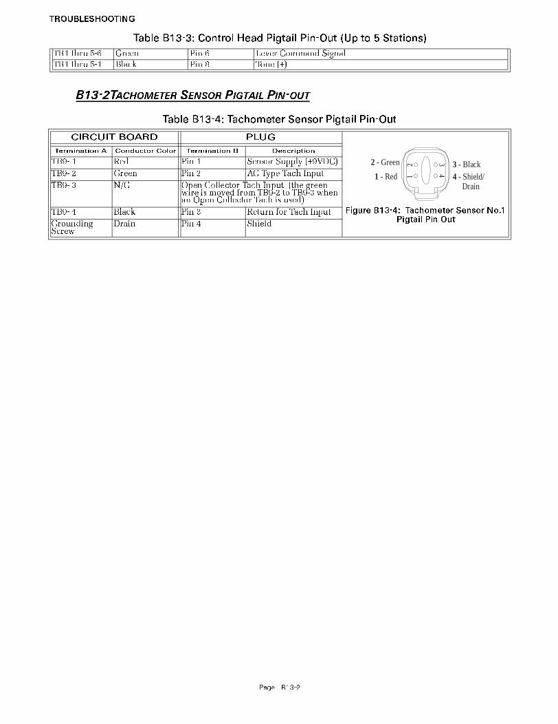
TROUBLESHOOTING
Page B13-2
B13-2TACHOMETER SENSOR PIGTAIL PIN-OUT
TB1 thru 5-6 Green Pin 6 Lever Command Signal
TB1 thru 5-1 Black Pin 8 Tone (+)
Table B13-4: Tachometer Sensor Pigtail Pin-Out
CIRCUIT BOARD PLUG
Figure B13-4: Tachometer Sensor No.1 Pigtail Pin Out
Termination A Conductor Color Termination B Description
TB9- 1 Red Pin 1 Sensor Supply (+9VDC)
TB9- 2 Green Pin 2 AC Type Tach Input
TB9- 3 N/C Open Collector Tach Input (the green wire is moved from TB9-2 to TB9-3 when an Open Collector Tach is used)
TB9- 4 Black Pin 3 Return for Tach Input
Grounding Screw
Drain Pin 4 Shield
Table B13-3: Control Head Pigtail Pin-Out (Up to 5 Stations)
12
432 - Green
1 - Red3 - Black4 - Shield/ Drain

PageB-3
MMC-172 Rev.Z-P 5 /04Factory Authorized Sales & Service Centers - International
Factory Authorized Sales & Service Centers - International
ZF Mathers, LLC 12125 Harbour Reach Drive
Mukilteo, WA 98275 USA
800-546-5455 / 425-583-1900
Fax: 425-493-1569
MMC-172, Rev. Z-P 5-04
ARGENTINA
Trimer S.A. T: 54-11-4580-0444
F: 54-11-4580-0440
(mail) PO Box 1772
Attn: Mariano Castroverde
1000 Buenos Aires, ARGENTINA
(ship) Fray J.S.M. de Oro 2030.40
1425 Buenos Aires, ARGENTINA
Carlos Dorian Friedlander3205
AUSTRALIA
ZF Australia Pty. Ltd.
www.zf.com.au
T: +61 (0)2 9679 5555
F: +61 (0)2 9679 5500
(mail) Locked Bag 6305
Blacktown BC, NSW 2148 AUSTRALIA
(ship) 14 Lidco Street
Arndell Park, NSW 2148
AUSTRALIA
Rodney Lean6948
BRAZIL
ZF do Brazil S.A. T: 5515-235-2301
F: 5515-235-2233
Avenida Conda Zepplin, 1935
CEP 18103-0000 Soroc, BRAZIL
Antonio Tucunduva7000
CHINA
ZF Shanghai Rep. Office
T: 0086 21 6301 4338
F: 0086 21 6301 6449
M: 13901655780
Room 2504, Jiangnan Building
No. 600 Luban Rd.
Shanghai 200023, PR CHINA
Tang Zhou Qing6953
DENMARK
ZF Danmark APS
www.zf-marine.com
T: +45 (0) 43 436243
F: +45 (0) 43 432643
Hesselager 21
Postbox 97
DK-2605, Brondby, DENMARK
Elisabeth Q. Sibbern7257
FINLAND
Mastervolt Finland T: 358-2-433-9990
F: 358-2-435-0085
Powerduo Oy
Haikankatu 2
FIN-21200, Raisio, FINLAND
Vesa Saarinen, Ari Bragge7655
FRANCE
Seimi
www.seimi.com
T: 33 2 98 46 11 02
F: 33 2 98 43 37 49
(mail) B.P. 30307
Brest Cedex, FRANCE 29603
(ship) Z.I.P. Du Moulin Blanc
Rue Alain Colas
29200 Brest, FRANCE
Mr. L. Gautier2190
Vidal Diffusion Marine
T: 33 494 08 68 20
F: 33 494 08 26 59
(mail) B.P. 97
Toulon Cedex 9, FRANCE
(ship) Z.I. Toulon -Est
Toulon Cedex 9,
FRANCE
David Elderkin3590
GERMANY
ADS Van Stigt
T: +31 (0) 183 650000
F: +31 (0) 183 650001
Avelingen - West 30
NL-4202 MS Gorinchem,
NETHERLANDS
Jan Hogenkamp7252
GREECE
Amaltheia T: 0030210 25 88 985
F: 0030210 25 89 986
13 Papaflessa Str.
143 43 N. Halkidona
Athens, GREECE
Demetris Kyriazis2386

Page
ICELAND
Merkur
T: 354-568-1044
F: 354-568-9958
M: 354-863-0312
Akralind 2
201 Kopavogur, ICELAND
Hrafn Sigurdasson, Johann Olafur Arsaelsson6525
IRELAND
ZF Great Britain Ltd.
T: 44-115-986-9211
F: 44-115-986-9261
Abbeyfield Road, Lenton
Nottingham, UNITED KINGDOM NG7
2SX
ENGLAND
Adi Licence7326
ITALY
SAIM S.p.A.
www.zf-marine.com
T: +39 02 488 831
F: +39 02 4884 3260
Via Donizetti, 9/11
I-20090 Assago
Milano, ITALY
Alex Busetto7093
ZF Hurth T: 011-390-464-580-555
F: 011-390-464-580-544
38062 Arco (TN) Italy
Via S. Andrea, 16, ITALY
Vittorio Rasera6477
ZF Padova S.p.A.
www.zf-marine.com
T: 0039-049-8299-550
F: 0039-049-8299-550
Via Panghe N. 48
Selvazzano/Padova, ITALY I-35030
7244
JAPAN
ZF Marine Japan Co. Ltd.
www.zf-marine.com
T: +81 (0) 3 5808 4521
F: +81 (0) 3 5808 4531
Fujikoshi Bldg. 1-10-11 Iriya Taito-ku
Tokyo, 110-0013
JAPAN
Y. Ikeda7253
KOREA
SE Jung Engineering Co.
T: 82-51-415-0591
F: 82-51-412-6361
#35-4 Namhangdong-1KA
Yeongdogu
Pusan, KOREA
M.G. Song1415
NETHERLANDS (Holland)
ADS / Van Stigt
T: +31 (0) 183 650000
F: +31 (0) 183 650001
Avelingen - West 30
NL-4202 MS Gorinchem,
NETHERLANDS
Jan Hogenkamp7252
Straathof Scheepselectra
T: 31 321-382315
F: 31 321-336151
Van de Plasschelaan 4
8251 PG Dronten, NETHERLANDS
Dick Straathof5446
MMC, CL, CR, MC
NEW ZEALAND
ZF Australia Pty. LTD
www.zf.com.au
T: +61 (0)2 9679 5555
F: +61 (0)2 9679 5500
(mail) Locked Bag 6305
Blacktown BC, NSW, AUSTRALIA 2148
(ship) 14 Lidco Street
Arndell Park, NSW, 2148
AUSTRALIA
Rodney Lean6948
MMC, CL, CR
NORWAY
KGK Norge AS
www.zf-group.no
T: +47 22 884 680
F: +47 22 720 902
Casper Storms Vei 19
Oslo, N-0664
NORWAY
Karl Baumgart7029
MMC, CL, CR
RUSSIA
ZF Transmissia 000 T: 7 (812) 324 54 72
F: 7 (812) 140 18 15
Suite 313
71, Marata Street
St. Petersburg, RUSSIA 191119
7313

PageB-5
SCOTLAND
ZF Great Britain Ltd.
T: 44-115-986-9211
F: 44-115-986-9261
Abbeyfield Road, Lenton
Nottingham, UNITED KINGDOM NG7
2SX
ENGLAND
Adi Licence7326
SINGAPORE
Mammoth Enterprises Pte. Ltd.
T: 65 6 44-88266
F: 65 6 44-89800
(mail) PO Box 283
Siglap Post Office, SINGAPORE 914503
(ship) 6-A Waringin Park
, SINGAPORE 416320
Steven Wee157
ZF South East Asia Pte.
www.zf-marine.com
T: +65 (0) 8 610177
F: +65 (0) 6861 9173
11 Tuas Drive 1
Singapore, 638678
Rep. of SINGAPORE
Daniel Poone7045
SOUTH AFRICA
ZF South Africa (Pty) Ltd T: 27 11 453 1818
F: 27 11 453 7506
(mail) PO Box 2098
Kempton Park, 1620 SOUTH AFRICA
(ship) C/O Barlows Power Systems
Cnr. Peter Barlow and Kasselss Vlei Rd
Bellville, Cape Town, SOUTH AFRICA
7261
SPAIN
ZF Espana, S.A.
www.zf-marine.com
T: +34 (91) 4852699
F: +34 (91) 6733931
Avda. Fuentermar, 11
Coslada (Madrid), 28820
SPAIN
Juanma Raposa5556
SWEDEN
KG Knutsson AB
T: +46 (0) 8 923 312
F: +46 (0) 8 929 599
Transmissionsdivisionen
Hammarbracken 8
S-191 81 Sollentuna, SWEDEN
Karl-Henry Pragsten7234
SWITZERLAND
Marine Parts Heimgartner
www.marineparts.ch
T: 41 1997 4090
F: 41 1997 4094
Pfaffikerstrasse 6
CH-8604 Volketswil
Zurich, SWITZERLAND
Rolf Heimgartner2419
TAIWAN
Asia Diesel Electric Corp. T: 886 7 333 1191
F: 886 7 334 6808
20th Floor
34 Min Chuan 1st Road
Kaohsuing, R.O.C. TAIWAN
Mike Ou5355
THAILAND
ZF Thailand Co. Ltd
www.zf-marine.com
T: +66 2 521 6520
F: +66 2 521 6523
159/33 Soi Vipawasee 64
Vipawadee-Rangsit Road
Laksi, Bangkok, Bangkok 10210
THAILAND
Reungpoj V7283
TURKEY
Niveko Makina Dis Ticaret Kollektif Sti
T: 90 212 287 27 80
F: 90 212 287 65 71
Lorenze Severin Moritz Weinstabl #
Ortaklar
Hasan Yelmen Cad No15, Istanbul Deri
Serbest Bolgesi, TR-34957 Tuzla
TURKEY
Mr. Georg Weinstabl7223
U.A.E.
ZF Middle East, LLC
www.zf-marine.com
T: 971-6-574-7074
F: 971-6-574-7174
(mail) PO Box 26093
Sharjah, U.A.E.
(ship) #502 Golden Tower Building
Sharjah,
U.A.E
M. Narasimhan (NARSI) 7030
MMC, CL, MC
UNITED KINGDOM (England)
Atlantis Marine Power Ltd.
www.atlantismarine.co.uk
T: 44 1752 208810
F: 44 1752 208811
Western Wood Way
Langage Science Park
Plymouth, Devon,, Plymouth PL7 5BG
ENGLAND
Richard Dix6932

Page
USA
ZF Mathers, LLC
www.zf-marine.com
T: 425-583-1900
F: 425-493-1569
12125 Harbour Reach Drive, Suite B
Mukilteo, WA 98275
USA
MMC, CL,CR, MC
ZFI Marine - US Headquarters
www.zf-marine.com
T: 954-581-4040
F: 954-581-4078
3131 SW 42nd Street
Fort Lauderdale, FL 33312
USA
Kelly Friedenberg6427
ZFI Marine - Gulf Coast Facility
www.zf-marine.com
T: 504-443-0501
F: 504-443-0504
161 James Drive West
Suite 120
St. Rose, LA 70087 USA
Randy Tredinich, Marc Kloor
ZFI Marine - West Coast
www.zf-marine.com
T: 425-583-1900
F: 425-493-1579
12125 Harbour Reach Drive, Suite B
Mukilteo, WA 98275
USA
Kevin Zwicker, Keith Kaelberer
ZFI Marine - Annapolis
www.zf-marine.com
T: 410-604-3320301 Pier One Road
Suite 102
Stevensville, MD 21666 USA
Stafford Barringer, Jeff Carter
ZFI Marine - Chicago
www.zf-marine.com
T: 847-478-6868
F: 847-478-6789
777 Hickory Hill Drive
Vernon Hills, IL 60061
USA
Jimmy Wong, Steve Vu
ZFI Marine - Irvine Service Center
T: 949-251-0140
F: 949-251-0150
1350 Reynolds Ave., Suite #110
Irvine, CA 92614
Cherie McAdams
USA
ZFI Marine - North Carolina
www.zf-marine.com
T: 252-504-3700
F: 252-504-3773
1350 Sensation Weigh
Beaufort, NC 28516
USA
Phil Organ
ZFI Marine - Rhode Island
www.zf-marine.com
T: 401-541-9014
F: 401-541-7223
M: JS: 401-261-1964
1 Mastead Drive
Warwick, RI 02886
USA
John Shea, Gil Bashaw

PageB14-7
ENG-127 Ver.1 7/02MicroCommander Qualitative Failure Analysis and Des ign Verification Test Procedure
MicroCommander 9110 Series
Servo Throttle – Servo Clutch
Qualitative Failure Analysis & Design
Verification Test Procedure
Version: 1.0
ZF Mathers , LLC.
12125 Harbour Reach Drive, Suite B
Mukilteo WA 98275
U.S.A.
Tel: 425-583-1900
Fax: 425-493-1569
Document #
ENG-127
AUTHOR
Joe Case
CHECKED
Joe Case
APPROVED
Jeff Turner
DATE
7/24/02
Qualitative Failure Analysis
The following qualitative failure analysis is provided to show compliance with:
Subchapter K Small Passenger Vessels, 46 CFR 121.620
Subchapter L Offshore Supply Vessels, 46 CFR 130.120
Subchapter T Small Passenger Vessels, 46 CFR 184.620:
121.620 Propulsion engine control systems.
(a) A vessel must have two independent means of controlling each propulsion
engine. Control must be provided for the engine speed, direction of shaft
rotation, and engine shutdown.
(1) One of the means may be the ability to readily disconnect the remote
engine control linkage to permit local operation.
(2) A multiple engine vessel with independent remote propulsion control
for each engine need not have a second means of controlling each
engine.
(b) In addition to the requirements of paragraph (a) of this section, a vessel must
have a reliable means for shutting down a propulsion engine, at the main pilot
house control station, which is independent of the engine's speed control.
(c) A propulsion engine control system, including pilothouse control, must be
designed so that a loss of power to the control system does not result in an
increase in shaft speed or propeller pitch.
(d) All microprocessor or computer based systems must meet the requirements of
part 62 in subchapter F of this chapter.
130.120 Propulsion control.
(a) Each vessel must have--
(1) A propulsion-control system operable from the pilothouse; and
(3) Control of propeller pitch, if a controllable-pitch propeller is fitted;
and
(4) Shutdown of each propulsion engine.
(a) The propulsion-control system operable from the pilothouse may constitute the
remote stopping-system required by Sec. 129.540 of this subchapter.
(b) Each propulsion-control system, including one operable from the pilothouse,
must be designed so that no one complete or partial failure of an easily replace-
(2) A means at each propulsion engine of readily disabling the
propulsion-control system to permit local operation.
(a) Each propulsion-control system operable from the pilothouse must enable--
(1) Control of the speed of each propulsion engine;
(2) Control of the direction of propeller-shaft rotation;

Page8
able component of the system allows the propulsion engine to overspeed or the
pitch of the propeller to increase.
184.620 Propulsion engine control systems.
(a) A vessel must have two independent means of controlling each propulsion
engine. Control must be provided for the engine speed, direction of shaft
rotation, and engine shutdown.
(1) One of the means may be the ability to readily disconnect the remote
engine control linkage to permit local operation.
(2) A multiple engine vessel with independent remote propulsion control
for each engine need not have a second means of controlling each
engine.
(a) In addition to the requirements of paragraph (a), a vessel must have a reliable
means for shutting down a propulsion engine, at the main pilothouse control
station, which is independent of the engine's speed control.
(b) A propulsion engine control system, including pilothouse control, must be
designed so that a loss of power to the control system does not result in an
increase in shaft speed or propeller pitch.
The ZF Mathers MicroCommander 9110 Series (servo throttle, servo clutch version) marine
engine controls offer single lever control of speed and direction. Each enclosure houses an
independent Control Processor and requires separate power supplies. The system operates on 12
or 24VDC power and can have up to five remote stations depending on the application. The
system sequences the operation of speed and shift in order to prevent an inexperienced operator
from mishandling the engine or transmission.
A requirement of the ZF Mathers MicroCommander system is that there be an engine ’STOP’
button at each remote station.
A standard feature is an alarm contact (normally open) to interface with the main alarm system of
the vessel. This switch will open and activate the alarm system with a power loss or CPU failure.
In addition, ZF Mathers provides audible tones at the Control Head locations to indicate system
faults.
ITEM
NUMBER
FAILED
COMPONENT
ALARM
STATUS
INITIAL
RESULT
FINAL
OUTCOME 1 ZF MATHERS CONTROL
HEAD
AUDIBLE TONE WILL SOUND
AT CONTROL HEAD
THROTTLE RESETS TO IDLE NO INCREASE IN ENGINE
RPM
CLUTCH SHIFTS TO NEUTRAL NO INCREASE IN SHAFT
SPEED
2 LOSS OF POWER SUPPLY ALARM CIRCUIT WILL OPEN
THROTTLE REMAINS AT
LAST COMMANDED
POSITION
NO INCREASE IN ENGINE
RPM
CLUTCH REMAINS AT LAST
COMMANDED POSITION
NO INCREASE IN SHAFT
SPEED
3 ZF MATHERS THROTTLE
FEEDBACK
POTENTIOMETER
AUDIBLE TONE WILL SOUND
AT CONTROL HEAD
THROTTLE RESETS TO IDLE
CLUTCH REMAINS AT LAST
COMMANDED POSITION
NO INCREASE IN SHAFT
SPEED
4 ZF MATHERS CLUTCH
FEEDBACK
POTENTIOMETER
AUDIBLE TONE WILL SOUND
AT CONTROL HEAD
THROTTLE RESETS TO IDLE NO INCREASE IN ENGINE
RPM
CLUTCH REMAINS AT LAST
COMMANDED POSITION
NO INCREASE IN SHAFT
SPEED
NO INCREASE IN ENGINE
RPM

PageB14-9
Design Verification Test Procedure
The MicroCommander 9110 Series (servo throttle, servp clutch version) Propulsion Control
System is compliant to the environmental design standards in 46 CFR 62.25-30.
The following test procedure covers the 4 items included in the Qualitative Failure Analysis; 1)
Control Head Potentiometer failure, 2) Loss of power supply, 3) Throttle Feedback Potentiometer
failure, and 4) Clutch Feedback Potentiometer failure.
1) Failure: Control Head Potentiometer failure.
a) Results: The Processor will shift to Neutral (if needed) and throttle will go to Idle, (if
needed).
b) Test Procedure
i) Turn power ON to both Port and Starboard Processors. Take command at a Control
Head.
ii) Move the Port and Starboard Control Head levers to approximately ½ Ahead.
iii) Locate the green wire coming from the Port Control Head in command, connecting to
pin 6 of the respective terminal block on the Processor circuit board. Disconnect it
from the Processor circuit board.
(1) The Port Processor will shift to Neutral (if needed) and throttle will go to Idle (if
needed).
(2) The Port Control Head will give an alarm tone indicating a faulty potentiometer.
iv) Move the Port and Starboard Control Head levers back to Neutral. Reconnect the
green wire.
v) Take command at the Control Head
vi) Repeat for Starboard side.
2) Failure: Power failure to MicroCommander 9110 Series
(A power failure to the MicroCommander 9110 Series circuit board will have the same
results as a failed microprocessor)
a) Results
i) Throttle signal will remain at last commanded position to and clutch shifts to neutral.
ii) LED at Control Heads will not be lit.
iii) Opposite engine still under power has full control.
b) Test Procedure.
i) Turn power ON to both Port and Starboard Processors. Take command at a Control
Head.
ii) Move the Port and Starboard Control Head levers to approximately ½ Ahead.
iii) Turn power OFF to the Port side only.
(1) Port side throttle will remain at last commanded position and clutch will shift to
neutral.
(2) LED on the Port side of the Control Head in command will go OFF.
(3) The Port Control Head will no longer have command of the engine and gear.
(4) The Starboard Control Head will still have full command of the Starboard engine
and gear.
iv) Turn power ON to the Port Processor. Return Control Head lever to Neutral. Take
command of the Port side.
(1) The Port Control Head will operate as usual-(Non-volatile memory)
v) Repeat test for Starboard Processor.

PageB14-10
3) Failure: Throttle Feedback Potentiometer failure
a) Results: Throttle will go to Idle (if needed).
b) Test Procedure.
i) Turn power ON to both Port and Starboard Processors. Take command at a Control
Head.
ii) Move the Port and Starboard Control Head levers to approximately ½ Ahead.
iii) On the Port Processor, locate the 3-pin plug above the throttle servo on the
Processor’s main circuit board. Disconnect the plug from the circuit board.
(1) The Port Processor will move the throttle to Idle.
(2) The Port Control Heads will give an alarm tone indicating a faulty throttle
feedback potentiometer.
iv) Move the Port and Starboard Control Head levers back to Neutral.
v) Replace the 3-pin plug.
vi) Acknowledge the error by pressing the transfer button.
vii) Repeat test for Starboard Processor.
4) Failure: Clutch Feedback Potentiometer failure
a) Results: Clutch will remain at last commanded position. Throttle will go to Idle (if
needed).
b) Test Procedure.
i) Turn power ON to both Port and Starboard Processors. Take command at a Control
Head.
ii) Move the Port and Starboard Control Head levers to approximately ½ Ahead.
iii) On the Port Processor, locate the 3-pin plug above the clutch servo on the Processor’s
main circuit board. Disconnect the plug from the circuit board.
(1) The Port Processor clutch servo will remain at last commanded position. Throttle
servo will drive to Idle.
(2) The Port Control Heads will give an alarm tone indicating a faulty clutch feedback
potentiometer.
iv) Move the Port and Starboard Control Head levers back to Neutral.
v) Replace the 3-pin plug.
vi) Acknowledge the error by pressing the transfer button.
vii) Repeat test for Starboard Processor.


APPENDIX C


Page C-1
Drawing 12271-1 Basic Pluggable System Diagram

Page C-2

Page C-3
Drawing 12271-2 Basic Processor Connections

Page C-4

Page C-5
Drawing 12271-3 Notes Page

Page C-6

Page C-3
Drawing 12379-2 Basic Hard-wired Processor Connections

Page C-4
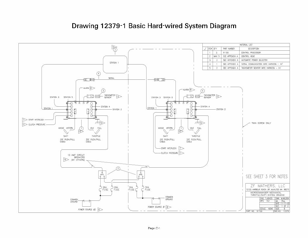
Page C-1
Drawing 12379-1 Basic Hard-wired System Diagram

Page C-2

Page C-5
Drawing 12379-3 Notes Page

Page C-6