micro-surfacing (quality control)
TRANSCRIPT

8/7/2019 MICRO-SURFACING (QUALITY CONTROL)
http://slidepdf.com/reader/full/micro-surfacing-quality-control 1/24
MICRO-SURFACING(QUALITY CONTROL)
A Guide To Quality Construction
OME
TECHNOLOGIES PRINT
8/7/2019 MICRO-SURFACING (QUALITY CONTROL)
http://slidepdf.com/reader/full/micro-surfacing-quality-control 2/24
This publication has been produced by the International Slurry Surfacing
Association (ISSA) to serve as a tool to assist contractor members and
buyer agencies in specifying and recognizing quality construction practices
for Micro-Surfacing projects. This document is meant to serve as a training
and educational tool only, and in no way should the procedures discussed
here be viewed as the only definitive solution or procedural methods that
are used on Micro-Surfacing projects.
As is the case in all construction activities there are many methods to
achieve the desired results. This document has been designed to hopefully
point out a method or procedure that may assist the contractor and buyer
agency in recognizing some of the things that can be done to realize a
successful project.
OME
TECHNOLOGIES PRINT
8/7/2019 MICRO-SURFACING (QUALITY CONTROL)
http://slidepdf.com/reader/full/micro-surfacing-quality-control 3/24
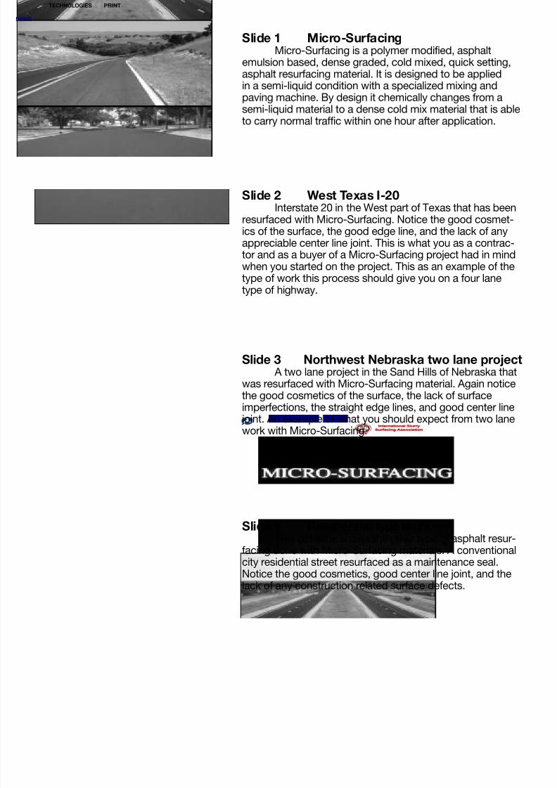
Slide 1 Micro-SurfacingMicro-Surfacing is a polymer modified, asphalt
emulsion based, dense graded, cold mixed, quick setting,asphalt resurfacing material. It is designed to be appliedin a semi-liquid condition with a specialized mixing andpaving machine. By design it chemically changes from asemi-liquid material to a dense cold mix material that is ableto carry normal traffic within one hour after application.
Slide 2 West Texas I-20Interstate 20 in the West part of Texas that has been
resurfaced with Micro-Surfacing. Notice the good cosmet-ics of the surface, the good edge line, and the lack of anyappreciable center line joint. This is what you as a contrac-tor and as a buyer of a Micro-Surfacing project had in mindwhen you started on the project. This as an example of the
type of work this process should give you on a four lanetype of highway.
Slide 3 Northwest Nebraska two lane projectA two lane project in the Sand Hills of Nebraska that
was resurfaced with Micro-Surfacing material. Again noticethe good cosmetics of the surface, the lack of surfaceimperfections, the straight edge lines, and good center linejoint. An example of what you should expect from two lanework with Micro-Surfacing.
Slide 4 Residential type workThis last slide shows the other type of asphalt resur-
facing done with Micro-Surfacing materials. A conventionalcity residential street resurfaced as a maintenance seal.Notice the good cosmetics, good center line joint, and thelack of any construction related surface defects.
OME
TECHNOLOGIES PRINT
8/7/2019 MICRO-SURFACING (QUALITY CONTROL)
http://slidepdf.com/reader/full/micro-surfacing-quality-control 4/24
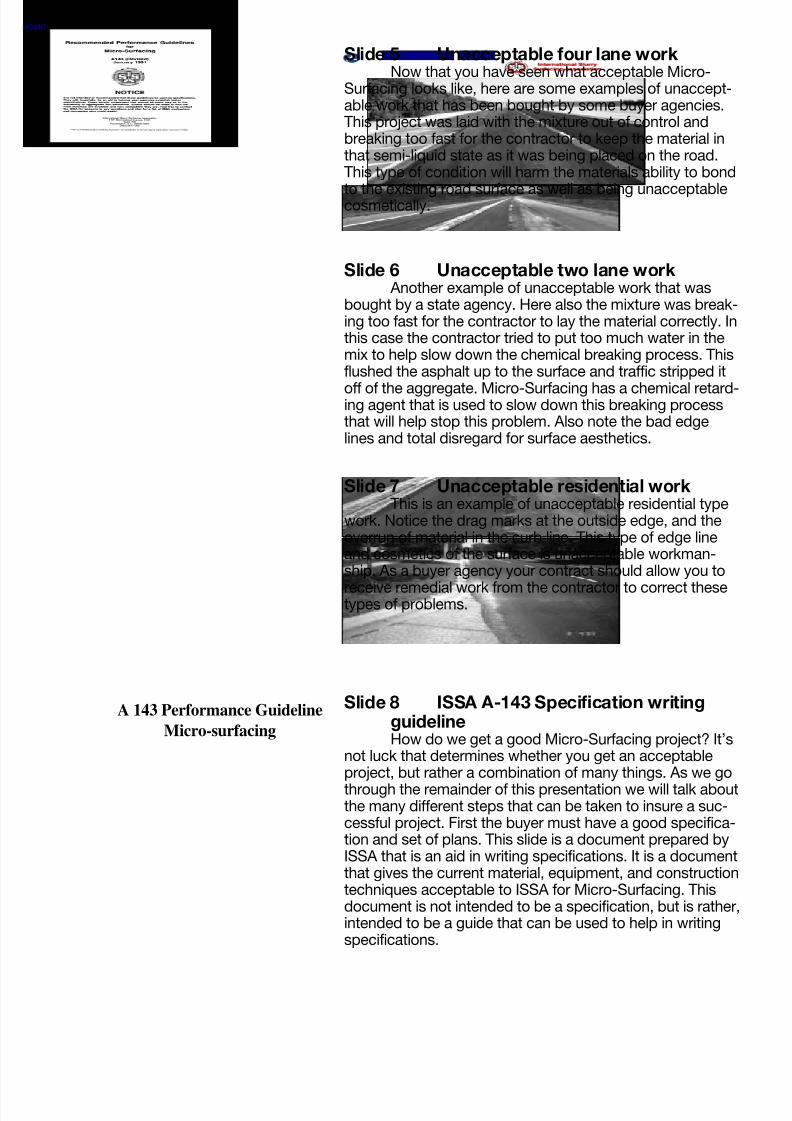
Slide 5 Unacceptable four lane workNow that you have seen what acceptable Micro-
Surfacing looks like, here are some examples of unaccept-able work that has been bought by some buyer agencies.This project was laid with the mixture out of control andbreaking too fast for the contractor to keep the material inthat semi-liquid state as it was being placed on the road.This type of condition will harm the materials ability to bond
to the existing road surface as well as being unacceptablecosmetically.
Slide 6 Unacceptable two lane workAnother example of unacceptable work that was
bought by a state agency. Here also the mixture was break-ing too fast for the contractor to lay the material correctly. Inthis case the contractor tried to put too much water in themix to help slow down the chemical breaking process. Thisflushed the asphalt up to the surface and traffic stripped it
off of the aggregate. Micro-Surfacing has a chemical retard-ing agent that is used to slow down this breaking processthat will help stop this problem. Also note the bad edgelines and total disregard for surface aesthetics.
Slide 7 Unacceptable residential workThis is an example of unacceptable residential type
work. Notice the drag marks at the outside edge, and theoverrun of material in the curb line. This type of edge lineand cosmetics of the surface is unacceptable workman-ship. As a buyer agency your contract should allow you to
receive remedial work from the contractor to correct thesetypes of problems.
Slide 8 ISSA A-143 Specification writingguidelineHow do we get a good Micro-Surfacing project? It’s
not luck that determines whether you get an acceptableproject, but rather a combination of many things. As we go
through the remainder of this presentation we will talk aboutthe many different steps that can be taken to insure a suc-cessful project. First the buyer must have a good specifica-tion and set of plans. This slide is a document prepared byISSA that is an aid in writing specifications. It is a documentthat gives the current material, equipment, and constructiontechniques acceptable to ISSA for Micro-Surfacing. Thisdocument is not intended to be a specification, but is rather,intended to be a guide that can be used to help in writingspecifications.
A 143 Performance Guideline
Micro-surfacing
OME
TECHNOLOGIES PRINT

8/7/2019 MICRO-SURFACING (QUALITY CONTROL)
http://slidepdf.com/reader/full/micro-surfacing-quality-control 5/24
Slide 10 Where not to use Micro-SurfacingKeep in mind that this is a thin lift of asphalt
resurfacing material that will not bridge over or correctfailed asphalt areas. These types of failed asphalt mustbe corrected before you can successfully resurface them.
Slide 11 Micro-Surfacing over failed asphaltAs the last slide pointed out, obliviously failed areas
must be corrected before they can be resurfaced. Here isan example of an area that was not corrected before beingresurfaced. Notice where the lay down machine has brokenthrough the bad area and left an unacceptable surfaceblemish.
Slide 12 Asphalt patch areaThis is an example of a repaired asphalt area that
is suitable for resurfacing with Micro-Surfacing material.You already know how to patch asphalt, so we won’t spendany time discussing it, but one point needs to be madeabout patching for Micro-Surfacing. This material does avery good job of filling in depressions in the road surface,which we will talk about later, but it is not very effectiveat smoothing out a bump or protrusion. Therefore it ispreferable to leave any patching areas with a correct profileor a slightly shallow profile rather than a raised profile.
Slide 9 Material Mix DesignAfter the project is let and before the contractor
goes to work a mix design must be submitted to the buyer,showing what the contractor plans on using for materialsand in what proportion he will mix them. The mix designwill also give the values of each of the materials used, forcomparison to the requirements given in the materialspecifications. Also before construction starts the mixing
and lay-down machine must be calibrated, to insure thateach of the ingredients used in the mix are in the correctproportions.
Mix Design
OME
TECHNOLOGIES PRINT

8/7/2019 MICRO-SURFACING (QUALITY CONTROL)
http://slidepdf.com/reader/full/micro-surfacing-quality-control 6/24
Slide 13 Pushed up edge lineAnother area that should be addressed before a
Micro-Surfacing application is plastic deformation orpushed up asphalt on the surface. Here is an examplewhere the surface lift has pushed up at the edge line.Once again the Micro-Surfacing material does a goodjob of filling in any low spots in the surface but it is notvery effective when used to correct high areas in the road.
The accepted method of correcting this type of problemis to cold mill the high areas of the pavement before youMicro-Surface.
Slide 14 Cold milling the edge lineWhen this type of corrective action is used it is note-
worthy to mention that you do not need to mill inches ofmaterial off of the surface. Rather do a skip mill operationwhere you only remove that portion of pavement that ispushed up and let the Micro-Surface material fill in any low
areas in the pavement. Of course the Micro-Surfacingmaterial will not correct the problem in the asphalt surfacethat caused the movement initially but it will buy you sometime on the road.
Slide 16 Fresh material over a large crackLets go over crack preparation work prior to a Micro-
Surfacing. This is an example of a Micro-Surfacing materialplaced over an unprepared crack. The crack appears to befilled, but even though we have a polymer modification inour asphalt we still can not stop full depth reflective cracksfrom reappearing. Micro-surfacing is somewhat effective onretarding small oxidation and hairline cracks , but not largereflective cracks.
Slide 15 Reflective crack through Micro-Surfacing
As seen here a crack has reappeared through twoyear old Micro-Surfacing material. Large reflective cracks
should always be treated prior to any asphalt resurfacingmaterial being applied. It is recommended that some typeof crack sealing material be used before any Micro-Surfacing is applied. It is the buyers decision of what typeof crack seal material to use, as there are many types avail-able. You must remember to insure that the crack sealingmaterial is compatible with asphaltic materials.
OME
TECHNOLOGIES PRINT

8/7/2019 MICRO-SURFACING (QUALITY CONTROL)
http://slidepdf.com/reader/full/micro-surfacing-quality-control 7/24
Slide 17 Crack sealingLarge cracks must be sealed with something prior
to resurfacing. One method that has gained a lot of accep-tance is a polypropoline, or polyester fiber suspended in anAC-10 asphalt and applied hot, through a wand. This slideis an example of this type of crack seal operation. Thecrack needs to be cleaned with compressed air, then thecrack seal material is applied into and over the crack. There
are many different types of crack sealers available and wearen’t promoting one over the other, but we are promotingthat some type of crack work be done.
Slide 18 Crack sealed street ready forresurfacing
This is an example of a street that is prepared forMicro-Surfacing, with the crack sealing operation alreadydone. Remember that most Micro-Surfacing applicationsare applied at a very thin application rate per square yard.
Therefore we have found that it works best when the cracksealing operation is done early enough that traffic can runon the seal material and pound it down into the crack orflatten it out on the road surface. This will allow the thin liftof Micro-Surfacing material to cover the crack sealer with-out leaving a bump in the road.
Slide 19 Debonding of Micro-Surfacing dueto road contaminates
When preparing a road for resurfacing it is importantto insure that you are bonding asphalt to asphalt and not
have any contaminates between that bond. Here is anexample of a one year old Micro-Surfacing material that hascome loose from the original pavement because the roadwas not sufficiently cleaned ahead of the application. Thishappens to be an animal carcass that was left on the pave-ment and surfaced over. The material has come off of thecontaminate and left an unsurfaced area.
Slide 20 Debonded areasThis is another example of debonding of the
surfacing material from the existing pavement surface. Thisillustrates an area where virgin aggregate from the dumptrucks that are feeding the lay down machine have spilledrock on the road and it was then surfaced over. The pointthat needs to made clear here, is that good cleaning mustbe done on the road before any Micro-Surfacing can beapplied or it may not stick or bond to the road.
OME
TECHNOLOGIES PRINT

8/7/2019 MICRO-SURFACING (QUALITY CONTROL)
http://slidepdf.com/reader/full/micro-surfacing-quality-control 8/24
Slide 21 Micro-Surfacing stockpile areaLets now take a few minutes to go over the stockpile
site, the support equipment, and the lay down machine.This first slide shows a stockpile area where the aggregateis screened, weighed, and loaded onto dump trucks fordelivery to the lay down machine. We suggest that eventhough the aggregate is select crushed material, that it bescreened to remove any oversize particles and contami-
nates before it is loaded onto trucks. Also in most areas ofthe country the aggregate is then weighed and a ticketmade that is delivered to the lay down inspector. At thestockpile site the dump trucks are loaded with emulsifiedasphalt and water while they are being loaded withaggregate.
Slide 23 Lift bed dump supportThere are basically three methods of delivering the
materials to the lay down machine. This is one methodwhere conventional dump trucks have liquid tanks on eachside of their dump beds that hold the emulsified asphalt onone side and the water on the other side. They lift their bedsto charge the lay down machine with aggregate and fill themachine with the liquids. This method works well enough ifthe project is out in the open spaces, but does not workwell if there are overhead obstructions on the road.
Slide 24 Conveyor belt dump supportAs shown here the lift bed dump support method
may not work very well when the roadway has overheadobstructions such as power line or heavy tree growth. Themethod shown here is a conventional dump truck that hasbeen fitted with a slide in support unit that holds the liquidsin a tank on each side and has a conveyor to discharge theaggregate without having to lift the truck bed. This methodwill solve the lifting of the bed problem in obstructed areasthat was just discussed.
Slide 22 Oversize material at the screeningplant
This shows why it is recommended that a screeningplant be used to screen the aggregate before it is delivered
to the lay down machine. The pile of material that can beseen below the screen is oversize aggregate that was in thematerial when it was delivered from the quarry. Also there issome dirt and grass that the loader operator got into whenhe was picking up material to load. Any oversize material orcontaminates that you can remove from the aggregatebefore it gets to the lay down machine will help with surfacecosmetics on the road.
OME
TECHNOLOGIES PRINT
8/7/2019 MICRO-SURFACING (QUALITY CONTROL)
http://slidepdf.com/reader/full/micro-surfacing-quality-control 9/24
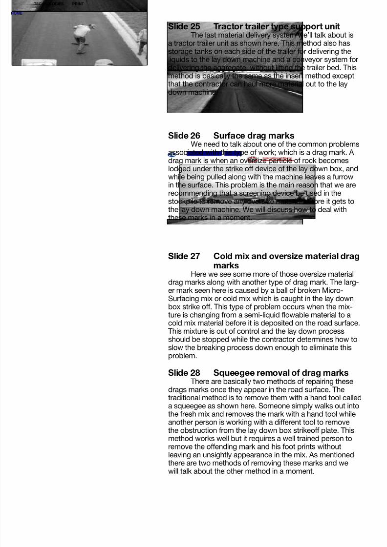
Slide 25 Tractor trailer type support unitThe last material delivery system we’ll talk about is
a tractor trailer unit as shown here. This method also hasstorage tanks on each side of the trailer for delivering theliquids to the lay down machine and a conveyor system fordelivering the aggregate, without lifting the trailer bed. Thismethod is basically the same as the insert method exceptthat the contractor can haul more material out to the lay
down machine.
Slide 26 Surface drag marksWe need to talk about one of the common problems
associated with this type of work; which is a drag mark. Adrag mark is when an oversize particle of rock becomeslodged under the strike off device of the lay down box, andwhile being pulled along with the machine leaves a furrowin the surface. This problem is the main reason that we are
recommending that a screening device be used in thestockpile to remove any oversize material before it gets tothe lay down machine. We will discuss how to deal withthese marks in a moment.
Slide 27 Cold mix and oversize material dragmarks
Here we see some more of those oversize materialdrag marks along with another type of drag mark. The larg-er mark seen here is caused by a ball of broken Micro-Surfacing mix or cold mix which is caught in the lay downbox strike off. This type of problem occurs when the mix-ture is changing from a semi-liquid flowable material to acold mix material before it is deposited on the road surface.This mixture is out of control and the lay down processshould be stopped while the contractor determines how toslow the breaking process down enough to eliminate thisproblem.
Slide 28 Squeegee removal of drag marks
There are basically two methods of repairing thesedrags marks once they appear in the road surface. Thetraditional method is to remove them with a hand tool calleda squeegee as shown here. Someone simply walks out intothe fresh mix and removes the mark with a hand tool whileanother person is working with a different tool to removethe obstruction from the lay down box strikeoff plate. Thismethod works well but it requires a well trained person toremove the offending mark and his foot prints withoutleaving an unsightly appearance in the mix. As mentionedthere are two methods of removing these marks and wewill talk about the other method in a moment.
OME
TECHNOLOGIES PRINT

8/7/2019 MICRO-SURFACING (QUALITY CONTROL)
http://slidepdf.com/reader/full/micro-surfacing-quality-control 10/24
Slide 29 Surface imperfections after handwork
As mentioned earlier the removal of drag marks witha hand tool requires a well trained person, so that the sur-face cosmetics after the drag mark has been removed isnot worse than before the hand work was done. As shownhere the hand work has left imperfections in the surface thatare not acceptable and probably look worse that the origi-
nal drag mark did. Contractor personal training is the keyhere.
Slide 30 Dirty strike off dragsThis as an example of another type of drag mark
that can be in a Micro-Surfacing project. This type of markis much shallower and smaller than those we have justtalked about. These imperfections are caused when the laydown box strike off becomes dirty with small particles of
aggregate and asphalt, sticking to the final strike off platecausing this indention in the surface.
Slide 31 Dirty strike off drag marksAnother example of dirty strike off drag marks in the
surface. As shown here this type of problem is most com-monly seen when a transverse joint is made. When making
a transverse joint the lay down box is lifted off of the roadand the asphalt and fine particles have a chance to hardenon the strike off plate. The solution to this problem is tophysically remove any material that has dried on the strikeoff every time a transverse joint is made or when this type ofsurface problem becomes apparent. We will talk about thisin greater detail when we are going over how to make atransverse joint.
Slide 32 Secondary strike off deviceAs we said earlier there are two methods of correct-
ing drag marks, so lets discuss the newer method. Thisdevice is called a “secondary strike off”, it is a surface tex-turing and surface cosmetic improvement device. The sec-ondary strike off mounts directly behind the lay down boxprimary strike off and is in contact with the fresh mix. It willremove most surface imperfections without requiring some-one to walk in the mix and remove them with a hand tool.This device does not actually remove what is causing thedrag mark in the primary strike off, that still must beremoved by hand. But this device will correct the imperfec-tions in the surface while you are working to remove thecause.
OME
TECHNOLOGIES PRINT

8/7/2019 MICRO-SURFACING (QUALITY CONTROL)
http://slidepdf.com/reader/full/micro-surfacing-quality-control 11/24
Slide 33 Secondary strike off removing dragmark
An example of the secondary strike off removing alarge drag mark. A drag mark is purposely put into the freshmix here to demonstrate the ability of the strike off, inremoving it.
Slide 34 Secondary strike off removing dirtyprimary strike off marks
This is an example of the secondary strike off remov-ing the serrations in the surface that are associated with theprimary strike off being dirty.
Slide 35 Secondary strike off improving thesurface texture
This last example of the secondary strike off showshow it can improve the surface texture and cosmetics as
well as correcting drag marks. Here you see a wet shinysurface on the mix between the primary strike off and thesecondary strike off, that indicates a mixture that has toomuch total liquids in it. While the contractor is working tolower the total liquids in the mix the secondary strike off iscorrecting the surface texture.
Slide 36 Good transverse jointThis is an example of a good transverse joint in a
Micro-Surfacing mix. Making transverse joints with anyasphalt material is a difficult process and in this next groupof slides we will talk about how to construct those jointswhen using Micro-Surfacing. The method we will be dis-cussing for constructing a good transverse joint is not theonly correct method that may be used, but is one of themethods.
OME
TECHNOLOGIES PRINT
8/7/2019 MICRO-SURFACING (QUALITY CONTROL)
http://slidepdf.com/reader/full/micro-surfacing-quality-control 12/24
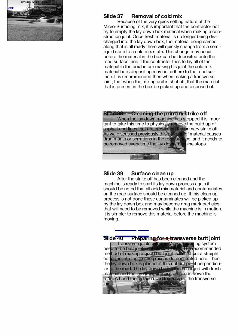
Slide 37 Removal of cold mixBecause of the very quick setting nature of the
Micro-Surfacing mix, it is important that the contractor nottry to empty the lay down box material when making a con-struction joint. Once fresh material is no longer being dis-charged into the lay down box, the material being carriedalong that is all ready there will quickly change from a semi-liquid state to a cold mix state. This change may occur
before the material in the box can be deposited onto theroad surface, and if the contractor tries to lay all of thematerial in the box before making his joint the cold mixmaterial he is depositing may not adhere to the road sur-face. It is recommended then when making a transversejoint, that when the mixing unit is shut off, that the materialthat is present in the box be picked up and disposed of.
Slide 39 Surface clean upAfter the strike off has been cleaned and the
machine is ready to start its lay down process again itshould be noted that all cold mix material and contaminateson the road surface should be cleaned up. If this clean upprocess is not done these contaminates will be picked upby the lay down box and may become drag mark particlesthat will need to be removed while the machine is in motion.It is simpler to remove this material before the machine ismoving.
Slide 40 Preparing for a transverse butt jointTransverse joints with the Micro-Surfacing system
need to be butt joints not overlap joints. The recommendedmethod of making a good butt joint is to first cut a straightedge line into the existing mix as demonstrated here. Thenthe lay down box is placed at this cut out point perpendicu-lar to the road. The lay down box is then charged with freshmaterial and the lay down process proceeds down theroad. A hand tool is then used to dress up the transversejoint.
Slide 38 Cleaning the primary strike offWhen the lay down machine has stopped it is impor-
tant to take this time to physically remove the build up ofasphalt and fines that are present on the primary strike off.As we discussed previously this build up of material causesdrag marks or serrations in the road surface, and it needs tobe removed every time the lay down machine stops.
OME
TECHNOLOGIES PRINT

8/7/2019 MICRO-SURFACING (QUALITY CONTROL)
http://slidepdf.com/reader/full/micro-surfacing-quality-control 13/24
Slide 41 Completed transverse butt jointThis is another example of a good transverse butt
joint that was constructed using the method we have justdiscussed. Notice that the line is perpendicular with theroad with good aesthetics. There is not a double thicknessof material as would be evident if an overlap joint was used.A joint like this will not be evident in a short period of time,as it will quickly blend into the overall road appearance.
Slide 42 Unacceptable transverse jointThis is an example of a transverse joint that was built
as an overlap joint. Notice the gap under the straight edgeon the joint, which shows an elevation difference. This gapwill cause a bump to be felt when traveling over the joint.Also the discolored material that is evident here is cold mix
material that was picked up by the lay down box when itwas pulled over the fresh or tender mix at the joint. Thisbump and discolored area will remain in the road surfacelong after the project is completed.
Slide 43 Unacceptable transverse jointHere is another example of an unacceptable trans-
verse joint. This joint shows an area that has too much totalliquids in the Micro-Surfacing material. The texture of the
joint should be the same as the rest of the road surface andnot be unsightly or flushed as shown here. Also you willnotice foot prints and other defects in the joint caused byworkers trying to correct the defect at the joint, rather thanconstructing it correctly the first time.
Slide 44 Good longitudinal jointThis slide shows a good longitudinal joint in a four
lane section of roadway. Constructing a longitudinal joint ona four lane highway is relatively easy as the normal processof constructing the road will insure that the longitudinal jointapplication will be placed when the first application ofmaterial is well cured and stable. It simply requires the con-tractor take care to minimize the overlap of material at thejoint interface. A maximum overlap at a longitudinal jointshould not exceed four inches at a typical joint.
OME
TECHNOLOGIES PRINT

8/7/2019 MICRO-SURFACING (QUALITY CONTROL)
http://slidepdf.com/reader/full/micro-surfacing-quality-control 14/24
Slide 46 Working the joint overlap down witha squeegee and secondary strike off
Another technique that is being used is to featheror minimize the material at the joint with a hand squeegeeplaced between the primary and secondary strike offs asshown here.
Slide 47 Excessively overlapped transversejoint
When the maximum overlap of four inches isexceeded it is impossible to work the two passes of materi-al down to any acceptable degree. Here we see an overlapof approximately eighteen inches and the associated prob-lem of having a double thickness of material. This excessiveoverlap will cause an elevation difference in the mix that willcause a bump when transitioning from one lane to the otheras is evident by the gap seen under the straight edge.
Slide 48 Overlapping fresh mixture at thelongitudinal joint
It was pointed out previously that making a longitudi-nal joint when the second application is placed next to acompletely cured first application is simply a matter of mini-mizing the overlap and working the second applicationdown. When making this longitudinal joint where the firstapplication is still in a tender or fresh state the process is alittle harder to do. As shown here the lay down box will tearthe fresh mix and create an unsightly appearance.
Slide 45 Working the joint overlap down byhand
As we pointed out in the previous slide, an overlapof up to four inches is permissible on a longitudinal joint,but care should be taken to minimize the thickness of thematerial at this joint. Here a worker is working the secondapplication of material down at the joint with a squeegeeto minimize the thickness. This is an acceptable practice
to aid in smoothing out the transition and ride when goingfrom one lane to the other.
OME
TECHNOLOGIES PRINT

8/7/2019 MICRO-SURFACING (QUALITY CONTROL)
http://slidepdf.com/reader/full/micro-surfacing-quality-control 15/24
Slide 49 Inside skids on the lay down boxAn aid in stopping this tearing of the fresh mix when
making a longitudinal joint is to use what is called an insideskid on the lay down box. The lay down box is pulled alongthe road surface with its weight being carried on long run-ners or skids, and this skid riding on the fresh mixture is thecause of the tearing we are discussing. The corrective pro-cedure is to mount another skid on the inside of the lay
down box. This allows the outside skid that is in contactwith the fresh mixture to be raised up so that it does nottear the mix. The weight of the lay down box is now beingcarried on the inside skid which is in contact with theunsurfaced portion of the road.
Slide 50 Hydraulically adjustable lay downboxes
Another device that is helpful in stopping this tearingof the fresh mixture is a hydraulic box that will allow thecontractor to quickly change the width of his lay down box.
With the introduction of these hydraulically adjustableboxes the contractor can change the width of the box inapproximately ten minutes. Also these boxes are fitted withinside skids at the factory which further helps the problemas we discussed previously.
Slide 51 Longitudinal alignmentThis is an example of the type of longitudinal align-
ment that can be achieved with the Micro-Surfacing sys-tem. This is an Interstate project in Nebraska where the outside lane was rut filled then surfaced. Notice the straightedge lines which were placed inside of the existing paintline.
Slide 52 Acceptable edge linesAnother example of an acceptable edge line or longi-
tudinal line on a four lane roadway. Notice that this systemcan produce a very straight and clean edge line.
OME
TECHNOLOGIES PRINT

8/7/2019 MICRO-SURFACING (QUALITY CONTROL)
http://slidepdf.com/reader/full/micro-surfacing-quality-control 16/24
Slide 53 Unacceptable longitudinal alignmentThis is an example of an edge line that should not
have happened or been accepted by the buyer agency. Asseen here the mixture had too much total liquids in the sys-tem, which ran off onto the shoulder. The mixture shouldhave had some of the liquids removed which would havestopped the free liquid run off. Also the operator of the laydown machine has a side shift device that was used to
over correct the alignment at the location shown.
Slide 54 Another example of a bad edge lineThis residential location also has a problem with the
longitudinal alignment that should not have happened. Thisproblem is also associated with the mixture being laid intoo wet of a condition, allowing the mixture to flow past theend of the box. A properly designed and applied Micro-
Surfacing material should not have excess liquids free inthe mix. Also the driver of the lay down machine was notfollowing a straight line when he was steering the machine.
Slide 55 String line edge lines?If the contractor has difficulty in achieving a straight
edge line, one thing that may help this is too require him toput down a string line to use as his guide mark for align-
ment. We are not recommending that all projects require astring line. Normally the existing paint line at the edge ofthe road is adequate for the contractor to use as his guidemark, but if he is not able to achieve the alignment that isdesired, then a string line guide mark will normally improvethe alignment.
Slide 56 Vertical abutment alignment
As can be seen here the lay down machines aredesigned to allow the contractor the ability to maintain avery straight edge line if the contractor so desires. Whenpulling the lay down box next to a vertical wall it requiresvery good machine control and the ability to maintain thatcontrol. Straight edge lines are possible.
OME
TECHNOLOGIES PRINT

8/7/2019 MICRO-SURFACING (QUALITY CONTROL)
http://slidepdf.com/reader/full/micro-surfacing-quality-control 17/24
Slide 57 Six foot rut box workThis industry currently has only two sizes of rut
boxes available. This slide shows the six foot rut box typicalapplication. Note that when both ruts in a lane are filled withthis box, twelve feet of the road is surfaced which requiresthe two passes make a longitudinal joint. The design andoperation of a rut box is such that the outside edge is ableto be laid with less material than the center part of the box.
This allows what is called feathering of the rut box edgewhere very little material is applied. This promotes verygood longitudinal joints with a rut box.
Slide 58 Five foot rut box workSeen here are two passes of rut box work with a five
foot rut box. The five foot box will leave a gap between theapplications, and will normally be followed with a surfaceapplication on top of the rut work. Notice again that the fivefoot rut box will feather the outside edge material down so
that the edge of the rut work is as thin as possible.
Slide 59 Unacceptable rut workHere is a project done with rut box work only, where
the contractor overran the project by sixty five percent sim-ply because he did not try to feather the outside part of the
mix down as the design of the box promotes. This excessmaterial was not needed to re-profile the rutted section andshould not have been accepted.
Slide 60 Under filled rut work applicationThis slide illustrates a rut application where the rut
was under filled with material. The design and intent of rutwork is to completely fill each individual rut with enoughmaterial to correct the roads profile. In this slide, that hasnot be accomplished. When the surface application isapplied over the rut work, the under filled area will nothave the same cross section as the rest of the surface.
OME
TECHNOLOGIES PRINT

8/7/2019 MICRO-SURFACING (QUALITY CONTROL)
http://slidepdf.com/reader/full/micro-surfacing-quality-control 18/24
Slide 61 Correct patching procedureOn most projects there will be some areas that the
contractor and buyer will want to correct with another appli-cation of material, or patch. This slide shows such an area,where a patch has been done correctly. It is normallyaccepted that when a patch is required, the patched areashould have the same surface cosmetics as the rest of theroad. This is accomplished by requiring that all patching be
done with the same lay down box that was originally usedto surface the road.
Slide 62 Unacceptable patch workThis is an example of an area that was patched with-
out using the accepted lay down box method we just dis-cussed. Here the contractor discharged material directlyonto the road surface and hand tooled the patch in. As canbe seen here this method leaves a completely different tex-
ture and appearance than the rest of the road, and shouldbe ruled an unacceptable patching process. As pointed outearlier it is recommended that if an area requires a patch itshould be patched with the same process and equipmentthat originally surfaced that area.
Slide 63 Unacceptable patchingAnother example of an unacceptable patch area.
Once again the contractor elected to do the patching bysimply hand working some mix into the problem area with
a hand tool. Remember that if an area requires a patch itshould be done with the same device that originally laid thematerial in that area.
Slide 64 Hand work areasThere are times that the lay down machine will not
be able to reach or maneuver into an area to lay the materi-al. In these cases it becomes necessary to hand work themixture over these areas. This is an example of hand work-ing an intersection approach. It is important to rememberthat the material is designed to cure very quickly and it willbe necessary for the contractor to have extra people avail-able to assist in the hand work process. The mixture mustbe spread and smoothed before it changes from a semi-liq-uid state to a cold mix state.
OME
TECHNOLOGIES PRINT
8/7/2019 MICRO-SURFACING (QUALITY CONTROL)
http://slidepdf.com/reader/full/micro-surfacing-quality-control 19/24
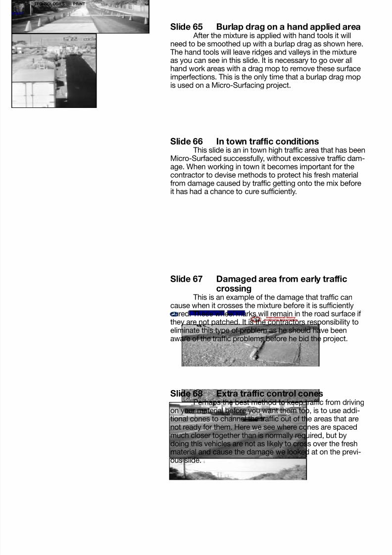
Slide 65 Burlap drag on a hand applied areaAfter the mixture is applied with hand tools it will
need to be smoothed up with a burlap drag as shown here.The hand tools will leave ridges and valleys in the mixtureas you can see in this slide. It is necessary to go over allhand work areas with a drag mop to remove these surfaceimperfections. This is the only time that a burlap drag mopis used on a Micro-Surfacing project.
Slide 66 In town traffic conditionsThis slide is an in town high traffic area that has been
Micro-Surfaced successfully, without excessive traffic dam-age. When working in town it becomes important for thecontractor to devise methods to protect his fresh materialfrom damage caused by traffic getting onto the mix before
it has had a chance to cure sufficiently.
Slide 67 Damaged area from early traffic
crossingThis is an example of the damage that traffic cancause when it crosses the mixture before it is sufficientlycured. These wheel marks will remain in the road surface ifthey are not patched. It is the contractors responsibility toeliminate this type of problem as he should have beenaware of the traffic problems before he bid the project.
Slide 68 Extra traffic control conesPerhaps the best method to keep traffic from driving
on your material before you want them too, is to use addi-tional cones to channel the traffic out of the areas that arenot ready for them. Here we see where cones are spacedmuch closer together than is normally required, but bydoing this vehicles are not as likely to cross over the freshmaterial and cause the damage we looked at on the previ-ous slide.
OME
TECHNOLOGIES PRINT

8/7/2019 MICRO-SURFACING (QUALITY CONTROL)
http://slidepdf.com/reader/full/micro-surfacing-quality-control 20/24
Slide 69 Dusting at an intersectionThere are times when a contractor must allow traffic
across the fresh mixture before he would like too, normallyat an intersection where crossing traffic is not diverted. Inthis instance the industry has a method to minimize thedamage this crossing traffic will cause. This method iscalled “dusting”, and it is accomplished by spreading someof the virgin mix aggregate over the fresh material to act as
a barrier to not allow vehicle tires to sink down into the mix-ture.
Slide 70 Crossing a dusted areaWe can see here where a vehicle is crossing the
fresh mixture on a dusted area without indenting the Micro-Surface and leaving a wheel print. It should be noted thateven when an area is dusted the early crossing of the mix-ture will still leave some surface blemishes and the road will
have a temporary aggregate dust stain at the dusted loca-tion. The dusting procedure is not a perfect control of thetraffic blemish problem but it is better than doing nothing atthose locations where you must allow traffic to cross thematerial early.
Slide 71 Manhole protectionManholes and utility covers must be protected from
the Micro-Surfacing material to insure that they are service-able after the application of material. Here we see a man-
hole cover that is being covered by material without anyprotection. The Micro-Surfacing material will stick to themetal of these covers so tightly that removal of it later willbe very difficult.
Slide 72 Protected ManholeThe accepted procedure is to cover the utility covers
with a plastic material before surfacing over them and thenremoving the plastic when the road is opened. This allowsfor easy removal of the material from the cover and puts theutility entrance back into service.
OME
TECHNOLOGIES PRINT

8/7/2019 MICRO-SURFACING (QUALITY CONTROL)
http://slidepdf.com/reader/full/micro-surfacing-quality-control 21/24
Slide 74 Successful constructionWhen the specifications are written correctly, the
plans spell out what is expected of the contractor, the roadis correctly prepared, the contractor has a good mix designand quality control system, this is what you as a buyeragency should get from a Micro-Surfacing project. A quality
asphalt resurfacing operation and a resurfaced road thatyou can be proud of, which will last for many years.
Slide 75 ISSA logoIf you need any help in setting up a Micro-Surfacing
project or have any questions that you would like answered
contact your local ISSA contractor or the ISSA headquar-ters directly.
Slide 73 Door knock cardThis slide shows an easy device that the contractor
can use to improve his public relations when on a city pro-ject. Any time a contractor is going to close or alter a streetto normal traffic he should notify the residents and busi-nesses that are going to be affected by his operations. Thisnotification is usually done by sending someone up to theaffected home or business and telling people what is going
to take place on their street and what they will need to do toaccommodate the construction activities. If that person isnot at home this card is left on their door explaining what isgoing to take place on their street.
DOOR KNOCK CARD
OME
TECHNOLOGIES PRINT
8/7/2019 MICRO-SURFACING (QUALITY CONTROL)
http://slidepdf.com/reader/full/micro-surfacing-quality-control 22/24
Notes:____________________________________________________________________________
__________________________________________________________________________________
__________________________________________________________________________________
__________________________________________________________________________________
__________________________________________________________________________________
__________________________________________________________________________________
__________________________________________________________________________________
__________________________________________________________________________________
__________________________________________________________________________________
__________________________________________________________________________________
__________________________________________________________________________________
__________________________________________________________________________________
__________________________________________________________________________________
__________________________________________________________________________________
__________________________________________________________________________________
__________________________________________________________________________________
__________________________________________________________________________________
__________________________________________________________________________________
__________________________________________________________________________________
__________________________________________________________________________________
__________________________________________________________________________________
__________________________________________________________________________________
__________________________________________________________________________________
__________________________________________________________________________________
__________________________________________________________________________________
__________________________________________________________________________________
For more information about other ISSA programs, publications, benefits, andactivities, please contact:
International Slurry Surfacing Association
#3 Church Circle, PMB 250Annapolis, MD 21401USA
Telephone 410-267-0023Fax 410-267-7546
International Slurry Surfacing Associatio
OME
TECHNOLOGIES PRINT

8/7/2019 MICRO-SURFACING (QUALITY CONTROL)
http://slidepdf.com/reader/full/micro-surfacing-quality-control 23/24
A Guide To Quality Construction
OME
TECHNOLOGIES PRINT

8/7/2019 MICRO-SURFACING (QUALITY CONTROL)
http://slidepdf.com/reader/full/micro-surfacing-quality-control 24/24
This publication is produced and distributed worldwide by the International Slurry SurfacingAssociation (ISSA). ISSA is an international non-profit organization composed of individuals,
corporations, and governmental agencies who provide the industry with machinery, materials,and services. The objectives of ISSA include:
• Provide technical data for monitoring and upgrading asphalt slurry systems (slurry seal andMicro-Surfacing) products;
• Advocate and encourage public and private interest in the use of asphalt slurry systems asefficient, effective, cost-saving, and safe additions to road maintenance programs;
• Encourage and promote ethical quality construction practices by all members of thisassociation within the industry; and
• Aid all members of the association in furthering the success of asphalt slurry systems.
International Slurry Surfacing Association
USA address:International Slurry Surfacing Association#3 Church Circle, PMB 250Annapolis, MD 21401USAPhone 410-267-0023Fax 410-267-7546Web www.slurry.org
Email [email protected]
Europe address:
OME
TECHNOLOGIES PRINT