micro motion model 1700 and 2700 installation manual
TRANSCRIPT

Installation Manual20001700, Rev CE
May 2015
Micro Motion® Model 1700 and 2700
Installation Manual

Safety messages
Safety messages are provided throughout this manual to protect personnel and equipment. Read each safety message carefullybefore proceeding to the next step.
Emerson Flow customer service
Email:
• Worldwide: [email protected]
• Asia-Pacific: [email protected]
Telephone:
North and South America Europe and Middle East Asia Pacific
United States 800-522-6277 U.K. 0870 240 1978 Australia 800 158 727
Canada +1 303-527-5200 The Netherlands +31 (0) 704 136 666 New Zealand 099 128 804
Mexico +41 (0) 41 7686 111 France 0800 917 901 India 800 440 1468
Argentina +54 11 4837 7000 Germany 0800 182 5347 Pakistan 888 550 2682
Brazil +55 15 3413 8000 Italy 8008 77334 China +86 21 2892 9000
Venezuela +58 26 1731 3446 Central & Eastern +41 (0) 41 7686 111 Japan +81 3 5769 6803
Russia/CIS +7 495 981 9811 South Korea +82 2 3438 4600
Egypt 0800 000 0015 Singapore +65 6 777 8211
Oman 800 70101 Thailand 001 800 441 6426
Qatar 431 0044 Malaysia 800 814 008
Kuwait 663 299 01
South Africa 800 991 390
Saudi Arabia 800 844 9564
UAE 800 0444 0684

Contents
Chapter 1 Planning .........................................................................................................................11.1 Meter components ...................................................................................................................... 11.2 Installation types ..........................................................................................................................11.3 Maximum cable lengths between sensor and transmitter ............................................................ 61.4 Output options ............................................................................................................................ 71.5 Environmental limits .................................................................................................................... 81.6 Hazardous area classifications ......................................................................................................81.7 Power requirements .................................................................................................................... 81.8 Orientation .................................................................................................................................. 91.9 Accessibility for maintenance .....................................................................................................10
Chapter 2 Mounting and sensor wiring for integral installations ...................................................112.1 Mounting and sensor wiring .......................................................................................................112.2 Rotate the transmitter on the sensor (optional) ......................................................................... 112.3 Rotate the user interface on the transmitter (optional) .............................................................. 132.4 Ground the meter components ................................................................................................. 14
Chapter 3 Mounting and sensor wiring for 4-wire remote installations .........................................163.1 Mounting options ...................................................................................................................... 163.2 Prepare the 4-wire cable ............................................................................................................ 203.3 Wire the transmitter to the sensor ............................................................................................. 233.4 Rotate the user interface on the transmitter (optional) .............................................................. 253.5 Ground the meter components ................................................................................................. 26
Chapter 4 Mounting and sensor wiring for 9-wire remote installations .........................................284.1 Mounting options ...................................................................................................................... 284.2 Prepare the 9-wire cable ............................................................................................................ 304.3 Wire the transmitter to the sensor using jacketed cable .............................................................364.4 Wire the transmitter to the sensor using shielded or armored cable ...........................................394.5 Rotate the user interface on the transmitter (optional) .............................................................. 444.6 Ground the meter components ................................................................................................. 46
Chapter 5 Mounting and sensor wiring for remote core processor with remote sensorinstallations ................................................................................................................. 485.1 Mounting options ...................................................................................................................... 485.2 Mount the remote core processor ..............................................................................................525.3 Prepare the 4-wire cable ............................................................................................................ 535.4 Wire the transmitter to the remote core processor .................................................................... 565.5 Prepare the 9-wire cable ............................................................................................................ 585.6 Wire the remote core processor to the sensor using jacketed cable ........................................... 645.7 Wire the remote core processor to the sensor using shielded or armored cable ......................... 675.8 Rotate the user interface on the transmitter (optional) .............................................................. 715.9 Ground the meter components ................................................................................................. 73
Chapter 6 Wiring the power supply .............................................................................................. 766.1 Wire the power supply ............................................................................................................... 76
Chapter 7 I/O wiring for Model 1700 and Model 2700 transmitters with analog outputs ............... 777.1 Basic analog wiring .................................................................................................................... 777.2 HART/analog single loop wiring ................................................................................................. 78
Contents
Installation Manual i

7.3 RS-485 point-to-point wiring ..................................................................................................... 797.4 HART multidrop wiring .............................................................................................................. 79
Chapter 8 I/O wiring for Model 1700 and Model 2700 transmitters with intrinsically safeoutputs ........................................................................................................................ 818.1 Safe area mA output wiring ........................................................................................................818.2 Safe area HART/analog single-loop wiring ..................................................................................828.3 Safe area HART multidrop wiring ............................................................................................... 838.4 Safe area frequency output/discrete output wiring .................................................................... 848.5 Hazardous area wiring ............................................................................................................... 84
Chapter 9 I/O wiring for Model 2700 transmitters with configurable input/outputs ......................909.1 Channel configuration ............................................................................................................... 909.2 mA/HART wiring ........................................................................................................................ 919.3 Frequency output wiring ............................................................................................................939.4 Discrete output wiring ............................................................................................................... 979.5 Discrete input wiring ................................................................................................................101
Chapter 10 I/O wiring for Model 2700 transmitters with Foundation fieldbus or PROFIBUS-PA ......10310.1 Foundation fieldbus wiring .......................................................................................................10310.2 PROFIBUS-PA wiring .................................................................................................................104
Chapter 11 Specifications ............................................................................................................. 10511.1 Electrical connections .............................................................................................................. 10511.2 Input/output signals ................................................................................................................ 10611.3 Local display ............................................................................................................................ 11011.4 Environmental limits ................................................................................................................ 11111.5 Physical specifications ..............................................................................................................111
Index ................................................................................................................................................116
Contents
ii Micro Motion® Model 1700 and 2700

1 PlanningTopics covered in this chapter:
• Meter components
• Installation types
• Maximum cable lengths between sensor and transmitter
• Output options
• Environmental limits
• Hazardous area classifications
• Power requirements
• Orientation
• Accessibility for maintenance
1.1 Meter componentsThe transmitter is one component of a Micro Motion device. The other major componentis the sensor.
A third component, called the core processor, provides additional memory and processingfunctions.
1.2 Installation typesThe transmitter was ordered and shipped for one of up to eight installation types. The fifthcharacter of the transmitter model number indicates the installation type.
Installation type indication for Model 1700 and Model 2700 transmittersFigure 1-1:
The model number is located on the device tag on the side of the transmitter.
Installation types for Model 1700 and Model 2700 transmittersTable 1-1:
Model code Description
R Remote mount 4-wire
I Integral
Planning
Installation Manual 1

Installation types for Model 1700 and Model 2700 transmitters (continued)Table 1-1:
Model code Description
E Remote enhanced core processor (painted aluminum housing) with remotetransmitter
C Remote mount 9-wire (painted aluminum housing)
B Remote core processor with remote transmitter
M Remote mount 4-wire (stainless steel housing)
P Remote mount 9-wire (stainless steel housing)
H(1) Remote mount 4-wire (painted aluminum housing) for connecting to Com-pact Density Meter (CDM), Fork Density Meter (FDM), Fork Viscosity Meter(FVM)
(1) This option is only available with the Model 2700 FOUNDATION Fieldbus™ transmitter
Integral installation (model code I)Figure 1-2:
The transmitter is mounted directly to the sensor. Integral installations do not require separate transmitterinstallation. Power supply and I/O must be field wired to the transmitter.
A
B
A. TransmitterB. Sensor
Planning
2 Micro Motion® Model 1700 and 2700

High-temperature meters with factory connection (model code I)Figure 1-3:
The transmitter is shipped with a flexible connection factory installed between the sensor and thetransmitter. The transmitter must be dismounted from its shipping location (spot-welded to the sensorcase) and then mounted separately. Power supply and I/O must be field wired to the transmitter.
A
B
C
A. SensorB. Transmitter or core processorC. Factory-installed flexible connection
4-wire remote installation for Coriolis meters (model code R or M)Figure 1-4:
The transmitter is installed remotely from the sensor. The 4-wire connection between the sensor andtransmitter must be field wired. Power supply and I/O must be field wired to the transmitter.
A
A
B
C
D
A. TransmitterB. Field-wired 4-wire connectionC. Core processorD. Sensor
Planning
Installation Manual 3

4-wire remote installation for density and viscosity meters (CDM, FDM,or FVM with fieldbus only)(model code H)
Figure 1-5:
The transmitter is installed remotely from the Compact Density Meter (CDM), Fork Density Meter (FDM), orFork Viscosity Meter (FVM). The 4-wire connection between the sensor and transmitter must be field wired.Power supply and I/O must be field wired to the transmitter.
A
B
C
A. TransmitterB. Field-wired 4-wire connectionC. Meter electronics
Planning
4 Micro Motion® Model 1700 and 2700

9-wire remote installation (model code P)Figure 1-6:
The transmitter and core processor are combined in a single unit that is installed remotely from the sensor.The 9-wire connection between the transmitter/core processor and the sensor must be field wired. Powersupply and I/O must be field wired to the transmitter.
A
A
B
C
D
A. TransmitterB. Field-wired 9-wire connectionC. Junction boxD. Sensor
Planning
Installation Manual 5

Remote core processor with remote sensor installation (model code B orE)
Figure 1-7:
The transmitter, core processor, and sensor are all mounted separately. The 4-wire connection betweenthe transmitter and core processor must be field wired. The 9-wire connection between the core processorand the sensor must be field wired. Power supply and I/O must be field wired to the transmitter. Thisconfiguration is sometimes called double-hop.
A E
D
C
F
B
A. Junction boxB. SensorC. TransmitterD. Field-wired 4-wire connectionE. Core processorF. Field-wired 9-wire connection
1.3 Maximum cable lengths between sensor andtransmitterThe maximum cable length between the sensor and transmitter that are separatelyinstalled is determined by cable type.
Maximum cable lengths between sensor and transmitterTable 1-2:
Cable type Wire gauge Maximum length
Micro Motion 4-wire Not applicable • 1000 ft (300 m) without Ex-approval
• 500 ft (150 m) with IIC rat-ed sensors
• 1000 ft (300 m) with IIB rat-ed sensors
Micro Motion 9-wire Not applicable 60 ft (20 m)
User-supplied 4-wire VDC 22 AWG (0.35 mm2) 300 ft (90 m)
Planning
6 Micro Motion® Model 1700 and 2700

Maximum cable lengths between sensor and transmitter (continued)Table 1-2:
Cable type Wire gauge Maximum length
VDC 20 AWG (0.5 mm2) 500 ft (150 m)
VDC 18 AWG (0.8 mm2) 1000 ft (300 m)
RS-485 22 AWG (0.35 mm2) orlarger
1000 ft (300 m)
1.4 Output optionsThe transmitter was ordered and shipped for one of up to 10 output options. You mustknow your transmitter output option to correctly install the transmitter. The eighthcharacter of the transmitter model number indicates the output option.
Output option indication for Model 1700 and Model 2700 transmittersFigure 1-8:
The model number is located on the device tag on the side of the transmitter.
Output options for Model 1700 transmittersTable 1-3:
Letter Description
A Analog outputs – one mA, one frequency, one RS-485
D Intrinsically safe analog outputs – two mA, one frequency
Output options for Model 2700 transmittersTable 1-4:
Letter Description
A Analog outputs – one mA, one frequency, one RS-485
B Configurable I/O channels (default configuration of two mA, one frequency)
C Configurable I/O channels (custom configuration )
D Intrinsically safe analog outputs – two mA, one frequency
E Intrinsically safe Foundation fieldbus H1 with standard function blocks
G PROFIBUS-PA
N Non-incendive Foundation fieldbus H1 with standard function blcoks
2 WirelessHART – one mA, one frequency, one RS-485
Planning
Installation Manual 7

Output options for Model 2700 transmitters (continued)Table 1-4:
Letter Description
3 WirelessHART – one mA, two configurable I/O channels (custom configura-tion)
4 Intrinsically safe WirelessHART – two mA, one frequency
1.5 Environmental limits
Environmental specificationsTable 1-5:
Type Value
Ambient temperature limits –40 to +140 °F (–40 to +60 °C)
Humidity limits 5 to 95% relative humidity, non-condensing at 140 °F (60 °C)
Vibration limits Meets IEC 60068-2-6, endurance sweep, 5 to 2000 Hz, 50 sweepcycles at 1.0 g
EMI effects Complies with EMC Directive 2004/108/EC per EN 61326 Indus-trial
Complies with NAMUR NE-21 (22.08.2007)
Ambient temperature effect onanalog outputs
On mA output: ±0.005% of span per °C
If possible, install the transmitter in a location that will prevent direct exposure to sunlight.The environmental limits for the transmitter may be further restricted by hazardous areaapprovals.
1.6 Hazardous area classificationsIf you plan to mount the transmitter in a hazardous area:
• Verify that the transmitter has the appropriate hazardous area approval. Eachtransmitter has a hazardous area approval tag attached to the transmitter housing.
• Ensure that any cable used between the transmitter and the sensor meets thehazardous area requirements.
1.7 Power requirementsSelf-switching AC/DC input, automatically recognizes supply voltage
• 85 to 265 VAC, 50/60 Hz, 6 watts typical, 11 watts maximum
• 18 to 100 VDC, 6 watts typical, 11 watts maximum
Planning
8 Micro Motion® Model 1700 and 2700

• Complies with low voltage directive 2006/95/EC per EN 61010-1 (IEC 61010-1) withamendment 2, and Installation (Overvoltage) Category II, Pollution Degree 2
NoteFor DC power:
• Power requirements assume a single transmitter per cable.
• At startup, the power source must provide a minimum of 1.5 amps of short-term current pertransmitter.
• Length and conductor diameter of the power cable must be sized to provide 18 VDCminimum at the power terminals, at a load current of 0.5 amps.
Cable sizing formulaFigure 1-9:
M = 18V + (R × L × 0.5A)• M: minimum supply voltage• R: cable resistance• L: cable length
Typical power cable resistance at 68 °F (20 °C)Table 1-6:
Wire gauge Resistance
14 AWG 0.0050 Ω/ft
16 AWG 0.0080 Ω/ft
18 AWG 0.0128 Ω/ft
20 AWG 0.0204 Ω/ft
2.5 mm2 0.0136 Ω/m
1.5 mm2 0.0228 Ω/m
1.0 mm2 0.0340 Ω/m
0.75 mm2 0.0460 Ω/m
0.50 mm2 0.0680 Ω/m
1.8 OrientationYou can mount the transmitter in any orientation as long as the conduit openings do notpoint upward.
CAUTION!
Upward-facing conduit openings risk condensation moisture entering the transmitter housing,which could damage the transmitter.
Planning
Installation Manual 9

1.9 Accessibility for maintenanceMount the meter in a location and orientation that satisfies the following conditions:
• Allows sufficient clearance to open the transmitter housing cover. Micro Motionrecommends 8–10 inches (200–250 mm) clearance at the rear of the transmitter.
• Provides clear access for installing cabling to the transmitter.
Planning
10 Micro Motion® Model 1700 and 2700

2 Mounting and sensor wiring forintegral installationsTopics covered in this chapter:
• Mounting and sensor wiring
• Rotate the transmitter on the sensor (optional)
• Rotate the user interface on the transmitter (optional)
• Ground the meter components
2.1 Mounting and sensor wiringThere are no separate mounting requirements for integral transmitters, and no need toconnect wiring between the transmitter and the sensor.
2.2 Rotate the transmitter on the sensor (optional)In integral installations, you can rotate the transmitter on the sensor up to 360º in 90ºincrements.
Mounting and sensor wiring for integral installations
Installation Manual 11

Components of an integral transmitterFigure 2-1:
A
B
C
D
A. TransmitterB. Transition ringC. Cap screwsD. Sensor
Procedure
1. Loosen each of the four cap screws (4 mm) that fasten the transmitter to the base.
2. Rotate the transmitter counter-clockwise so that the cap screws are in the unlockedposition.
3. Gently lift the transmitter straight up, disengaging it from the cap screws.
ImportantDo not disconnect or damage the wires that connect the transmitter to the core processor.
4. Rotate the transmitter to the desired orientation.
ImportantDo not pinch or stress the wires.
The slots on the transition ring should be aligned with the cap screws.
5. Gently lower the transmitter onto the base, inserting the cap screws into the slots.
6. Rotate the transmitter clockwise so that the cap screws are in the locked position.
7. Tighten the cap screws, torquing to 2.3 to 3.4 N-m.
Mounting and sensor wiring for integral installations
12 Micro Motion® Model 1700 and 2700

2.3 Rotate the user interface on the transmitter(optional)The user interface on the transmitter electronics module can be rotated 90º or 180° fromthe original position.
Display componentsFigure 2-2:
A
B
C
G
E
F
D
A. Transmitter housingB. Sub-bezelC. Display moduleD. Display screwsE. End-cap clampF. Cap screwG. Display cover
Notes
• When using the touch buttons, you must cover at least an 8 mm diameter circle over thesurface above the touch button: using your thumb may be more effective because it has agreater surface area.
• When the housing cover is removed, the touch buttons do not function.
Procedure
1. Shut off power to the unit.
2. Remove the end-cap clamp by removing the cap screw.
3. Turn the display cover counterclockwise to remove it from the main enclosure.
4. Carefully loosen (and remove if necessary) the semicaptive display screws whileholding the display module in place.
5. Carefully pull the display module out of the main enclosure until the sub-bezel pinterminals are disengaged from the display module.
Mounting and sensor wiring for integral installations
Installation Manual 13

NoteIf the display pins come out of the board stack with the display module, remove the pins andreinstall them.
6. Rotate the display module to the desired position.
7. Insert the sub-bezel pin terminals into the display module pin holes to secure thedisplay in its new position.
8. If you have removed the display screws, line them up with the matching holes on thesub-bezel, then reinsert and tighten them.
9. Place the display cover onto the main enclosure.
10. Turn the display cover clockwise until it is snug.
11. Replace the end-cap clamp by reinserting and tightening the cap screw.
12. Restore power to the transmitter.
2.4 Ground the meter componentsIn an integral installation, all components are grounded together.
Prerequisites
If national standards are not in effect, adhere to the following guidelines for grounding:
• Use copper wire, 14 AWG (2.5 mm2) or larger wire size.
• Keep all ground leads as short as possible, less than 1 Ω impedance.
• Connect ground leads directly to earth, or follow plant standards.
Procedure
Ground via the piping, if possible (see sensor documentation). If grounding via the pipingis not possible, ground according to applicable local standards using the transmitter’sinternal or external ground screw.
Mounting and sensor wiring for integral installations
14 Micro Motion® Model 1700 and 2700

Transmitter internal grounding screwFigure 2-3:
Transmitter external grounding screwFigure 2-4:
Mounting and sensor wiring for integral installations
Installation Manual 15

3 Mounting and sensor wiring for 4-wire remote installationsTopics covered in this chapter:
• Mounting options
• Prepare the 4-wire cable
• Wire the transmitter to the sensor
• Rotate the user interface on the transmitter (optional)
• Ground the meter components
3.1 Mounting optionsThere are two options available for mounting the transmitter:
• Mount the transmitter to a wall or flat surface.
• Mount the transmitter to an instrument pole.
3.1.1 Mount the transmitter to a wallPrerequisites
• Micro Motion recommends the use of 5/16-18 (8 mm–1.25) fasteners that canwithstand the process environment. Micro Motion does not supply bolts or nuts aspart of the standard offering (general purpose bolts and nuts are available as anoption).
• Ensure that the surface is flat and rigid, does not vibrate, or move excessively.
• Confirm that you have the necessary tools, and the mounting kit shipped with thetransmitter.
Procedure
1. If desired, re-orient the transmitter on the mounting bracket.
a. Remove the junction end-cap from the junction housing.
b. Loosen each of the four cap screws (4 mm).
c. Rotate the bracket so that the transmitter is oriented as desired.
d. Tighten the cap screws, torquing to 30 to 38 in-lbs (3 to 4 N-m).
e. Replace the junction end-cap.
Mounting and sensor wiring for 4-wire remote installations
16 Micro Motion® Model 1700 and 2700

Components of 4-wire remote mount transmitter (aluminumhousing)
Figure 3-1:
B
D
C
A
A. TransmitterB. Mounting bracketC. Cap screwsD. End-cap
Mounting and sensor wiring for 4-wire remote installations
Installation Manual 17

Components of a 4-wire remote mount transmitter (stainless steelhousing)
Figure 3-2:
B
D
C
A
A. TransmitterB. Mounting bracketC. Cap screwsD. End-cap
2. Attach the mounting bracket to the wall.
3.1.2 Mount the transmitter to an instrument polePrerequisites
• Use two 5/16-inch U-bolts for 2-inch pipe, and four matching nuts, that canwithstand the process environment. Micro Motion does not supply U-bolts or nuts(appropriate bolts and nuts are available as an option).
• Ensure the instrument pole extends at least 12 inches (305 mm) from a rigid base,and is no more than 2 inches (50.8 mm) in diameter.
Mounting and sensor wiring for 4-wire remote installations
18 Micro Motion® Model 1700 and 2700

Procedure
1. If desired, re-orient the transmitter on the mounting bracket.
a. Remove the junction end-cap from the junction housing.
b. Loosen each of the four cap screws (4 mm).
c. Rotate the bracket so that the transmitter is oriented as desired.
d. Tighten the cap screws, torquing to 30 to 38 in-lbs (3 to 4 N-m).
e. Replace the junction end-cap.
Components of 4-wire remote mount transmitter (aluminumhousing)
Figure 3-3:
B
D
C
A
A. TransmitterB. Mounting bracketC. Cap screwsD. End-cap
Mounting and sensor wiring for 4-wire remote installations
Installation Manual 19

Components of a 4-wire remote mount transmitter (stainless steelhousing)
Figure 3-4:
B
D
C
A
A. TransmitterB. Mounting bracketC. Cap screwsD. End-cap
2. Attach the mounting bracket to an instrument pole.
3.2 Prepare the 4-wire cable
ImportantFor user-supplied cable glands, the gland must be capable of terminating the drain wires.
NoteIf you are installing unshielded cable in continuous metallic conduit with 360º termination shielding,you only need to prepare the cable – you do not need to perform the shielding procedure.
Mounting and sensor wiring for 4-wire remote installations
20 Micro Motion® Model 1700 and 2700
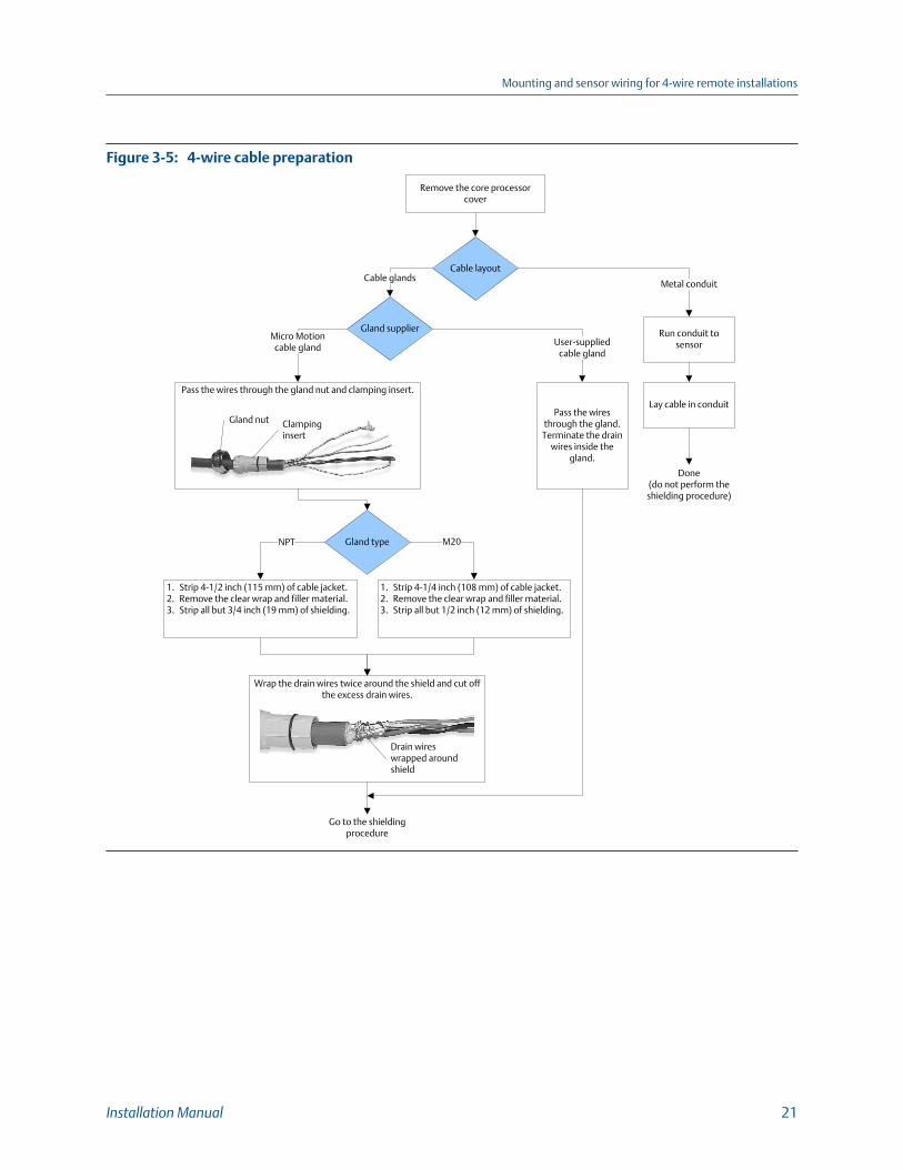
4-wire cable preparationFigure 3-5:
Cable layout
Run conduit to sensor
Metal conduit
Wrap the drain wires twice around the shield and cut off the excess drain wires.
Micro Motioncable gland
Pass the wires through the gland.
Terminate the drain wires inside the
gland.
Cable glands
Remove the core processor cover
Go to the shielding procedure
Done(do not perform the shielding procedure)
Gland supplierUser-supplied
cable gland
Lay cable in conduit
Drain wires wrapped around shield
Gland type
Pass the wires through the gland nut and clamping insert.
Clampinginsert
Gland nut
1. Strip 4-1/2 inch (115 mm) of cable jacket.2. Remove the clear wrap and filler material.3. Strip all but 3/4 inch (19 mm) of shielding.
1. Strip 4-1/4 inch (108 mm) of cable jacket.2. Remove the clear wrap and filler material.3. Strip all but 1/2 inch (12 mm) of shielding.
NPT M20
Mounting and sensor wiring for 4-wire remote installations
Installation Manual 21

4-wire cable shieldingFigure 3-6:
Assemble the Gland1. Fold the shield or braid back over the clamping insert and 1/8 inch
(3 mm) past the O-ring.2. Install the gland body into the conduit opening on the core processor housing.3. Insert the wires through gland body and tighten the gland nut onto the gland body.
Apply the Heat Shrink1. Slide the shielded heat shrink over the drain wires. Ensure that the
wires are completely covered. 2. Apply heat (250 °F or 120 °C) to shrink the tubing. Do not burn the
cable.3. Position the clamping insert so the interior end is flush with the braid
of the heat shrink.
Cable shield type
Braided(armored cable)
Foil(shielded cable)
Done
Terminate the shield and drain wires in the
gland
Assemble the gland according to vendor
instructions
Gland supplierMicro Motion
cable glandUser-supplied
cable gland
From the preparation procedure
After heat applied
Shield folded back Gland body
Gland type M20
Trim 7 mm from the shielded heat shrink
Shielded heatshrink
Trim
NPT
3.2.1 4-wire cable types and usageMicro Motion offers two types of 4-wire cable: shielded and armored. Both types containshield drain wires.
The 4-wire cable supplied by Micro Motion consists of one pair of red and black 18 AWG(0.75 mm2) wires for the VDC connection, and one pair of white and green 22 AWG(0.35 mm2) wires for the RS-485 connection.
Mounting and sensor wiring for 4-wire remote installations
22 Micro Motion® Model 1700 and 2700

User-supplied 4-wire cable must meet the following requirements:
• Twisted pair construction.
• Applicable hazardous area requirements, if the core processor is installed in ahazardous area.
• Wire gauge appropriate for the cable length between the core processor and thetransmitter.
Wire gaugeTable 3-1:
Wire gauge Maximum cable length
VDC 22 AWG (0.35 mm2) 300 ft (90 m)
VDC 20 AWG (0.5 mm2) 500 ft (150 m)
VDC 18 AWG (0.8 mm2) 1000 ft (300 m)
RS-485 22 AWG (0.35 mm2) or larger 1000 ft (300 m)
3.3 Wire the transmitter to the sensor1. Connect the cable to the sensor-mounted core processor as described in the sensor
documentation.
2. Feed the wires from the sensor through the conduit opening on the transmitter.
3. Connect wires to the appropriate terminals on the mating connector.
TipYou may find it easier to unplug the mating connector to connect the wires. If you do so,remember to firmly reseat the mating connector and tighten the mating connector screws sothat the mating connector cannot accidentally come loose.
Mounting and sensor wiring for 4-wire remote installations
Installation Manual 23

Wiring path for transmitters with aluminum housingFigure 3-7: A
C
VDC+VDC –
RS-485A
RS-485B
B
A. 4-wire cableB. Transmitter conduit openingC. Mating connector
Wiring path for transmitters with stainless steel housingFigure 3-8:
A
C
VDC+VDC –
RS-485A
RS-485B
B
A. 4-wire cableB. Transmitter conduit openingC. Mating connector
Mounting and sensor wiring for 4-wire remote installations
24 Micro Motion® Model 1700 and 2700

3.4 Rotate the user interface on the transmitter(optional)The user interface on the transmitter electronics module can be rotated 90º or 180° fromthe original position.
Display componentsFigure 3-9:
A
B
C
G
E
F
D
A. Transmitter housingB. Sub-bezelC. Display moduleD. Display screwsE. End-cap clampF. Cap screwG. Display cover
Procedure
1. Shut off power to the unit.
2. Remove the end-cap clamp by removing the cap screw.
3. Turn the display cover counterclockwise to remove it from the main enclosure.
4. Carefully loosen (and remove if necessary) the semicaptive display screws whileholding the display module in place.
5. Carefully pull the display module out of the main enclosure until the sub-bezel pinterminals are disengaged from the display module.
NoteIf the display pins come out of the board stack with the display module, remove the pins andreinstall them.
6. Rotate the display module to the desired position.
Mounting and sensor wiring for 4-wire remote installations
Installation Manual 25

7. Insert the sub-bezel pin terminals into the display module pin holes to secure thedisplay in its new position.
8. If you have removed the display screws, line them up with the matching holes on thesub-bezel, then reinsert and tighten them.
9. Place the display cover onto the main enclosure.
10. Turn the display cover clockwise until it is snug.
11. Replace the end-cap clamp by reinserting and tightening the cap screw.
12. Restore power to the transmitter.
3.5 Ground the meter componentsIn 4-wire remote installations, the transmitter and sensor are grounded separately.
Prerequisites
CAUTION!
Improper grounding could cause inaccurate measurements or meter failure.
NoteFor hazardous area installations in Europe, refer to standard EN 60079-14 or national standards.
If national standards are not in effect, adhere to the following guidelines for grounding:
• Use copper wire, 14 AWG (2.5 mm2) or larger wire size.
• Keep all ground leads as short as possible, less than 1 Ω impedance.
• Connect ground leads directly to earth, or follow plant standards.
Procedure
1. Ground the sensor according to the instructions in the sensor documentation.
2. Ground the transmitter according to applicable local standards, using thetransmitter’s internal or external ground screw.
Mounting and sensor wiring for 4-wire remote installations
26 Micro Motion® Model 1700 and 2700

Transmitter internal grounding screwFigure 3-10:
Transmitter external grounding screwFigure 3-11:
Mounting and sensor wiring for 4-wire remote installations
Installation Manual 27

4 Mounting and sensor wiring for 9-wire remote installationsTopics covered in this chapter:
• Mounting options
• Prepare the 9-wire cable
• Wire the transmitter to the sensor using jacketed cable
• Wire the transmitter to the sensor using shielded or armored cable
• Rotate the user interface on the transmitter (optional)
• Ground the meter components
4.1 Mounting optionsThere are two options available for mounting the transmitter:
• Mount the transmitter to a wall or flat surface.
• Mount the transmitter to an instrument pole.
4.1.1 Mount the transmitter to a wallPrerequisites
• Micro Motion recommends the use of 5/16-18 (8 mm–1.25) fasteners that canwithstand the process environment. Micro Motion does not supply bolts or nuts aspart of the standard offering (general purpose bolts and nuts are available as anoption).
• Ensure that the surface is flat and rigid, does not vibrate, or move excessively.
• Confirm that you have the necessary tools, and the mounting kit shipped with thetransmitter.
Procedure
1. If desired, re-orient the transmitter on the mounting bracket.
a. Loosen each of the four cap screws (4 mm).
b. Rotate the bracket so that the transmitter is oriented as desired.
c. Tighten the cap screws, torquing to 30 to 38 in-lbs (3 to 4 N-m).
Mounting and sensor wiring for 9-wire remote installations
28 Micro Motion® Model 1700 and 2700

Components of 9-wire remote mount transmitterFigure 4-1:
A
B
C
A. TransmitterB. Cap screwsC. Mounting bracket
2. Attach the mounting bracket to the wall.
4.1.2 Mount the transmitter to an instrument polePrerequisites
• Use two 5/16-inch U-bolts for 2-inch pipe, and four matching nuts, that canwithstand the process environment. Micro Motion does not supply U-bolts or nuts(appropriate bolts and nuts are available as an option).
• Ensure the instrument pole extends at least 12 inches (305 mm) from a rigid base,and is no more than 2 inches (50.8 mm) in diameter.
Procedure
1. If desired, re-orient the transmitter on the mounting bracket.
a. Loosen each of the four cap screws (4 mm).
b. Rotate the bracket so that the transmitter is oriented as desired.
c. Tighten the cap screws, torquing to 30 to 38 in-lbs (3 to 4 N-m).
Mounting and sensor wiring for 9-wire remote installations
Installation Manual 29

Components of 9-wire remote mount transmitterFigure 4-2:
A
B
C
A. TransmitterB. Cap screwsC. Mounting bracket
2. Attach the mounting bracket to an instrument pole.
4.2 Prepare the 9-wire cableMicro Motion supplies three types of 9-wire cable: jacketed, shielded, and armored. Thetype of cable you are using determines how you will prepare the cable.
Perform the cable preparation procedure appropriate for your cable type.
Mounting and sensor wiring for 9-wire remote installations
30 Micro Motion® Model 1700 and 2700

Preparing jacketed cableFigure 4-3:
1. Trim 4 inches (100 mm) of cable jacket.2. Remove the clear wrap and filler material.3. Remove the foil that is around the insulated wires
and separate them.
4. Identify the drain wires in the cable and bring them together. Fan the other wires to the outside of the cable. Twist the drain wires together.
5. Slide the 3-inch (75 mm) heat-shrink tubing over the drain wires. Push the tubing as close as possible to the cable jacket.
6. Slide the 1 ½ inch (40 mm) long heat-shrink tubing over the cable jacket. The tubing should completely cover all portions of the drain wires that remain exposed next to the cable jacket.
6. Without burning the cable, apply heat to shrink all tubing. Recommended temperature is 250 °F (121 °C).
1. Trim 4 ½ inches (115 mm) of cable jacket.2. Remove the clear wrap and filler material.3. Remove the foil that is around the insulated wires
and separate them.
4. Identify the drain wires in the cable. Clip off each drain wire as close as possible to the cable jacket.
7. Allow the cable to cool, then strip ¼ inch (5 mm) of insulation from each wire.
5. Slide the 1 ½ inch (40 mm) heat-shrink tubing over the wires and cable jacket. The tubing should completely cover the clipped ends of the drain wires.
Trim cable jacket
Drain wires clipped
Heat-shrink tubing
Trim cable jacket
Heat-shrink tubing over cable jacket
7. Without burning the cable, apply heat to shrink all tubing. Recommended temperature is 250 °F (121 °C).
8. Allow the cable to cool, then strip ¼ inch (5 mm) of insulation from each wire.
Heat-shrink tubing over drain wires
Prepare jacketed cable at the
transmitter end
Prepare jacketed cable at the sensor
end
Mounting and sensor wiring for 9-wire remote installations
Installation Manual 31

Preparing shielded or armored cableFigure 4-4:
1. Without cutting the shield, strip 9 inches (225 mm) of cable jacket.
2. Strip 8 ½ inches (215 mm) of braided shield, so ½ inch (10 mm) of shield remains exposed.
3. Remove the foil shield that is between the braided shield and inner jacket.
4. Strip 4 inches (100 mm) of inner jacket.
5. Remove the clear wrap and filler material.6. Remove the foil that is around the insulated wires and
separate them.7. Identify the drain wires in the cable and bring them
together. Fan the other wires to the outside of the cable. Twist the drain wires together.
8. Slide the 3-inch (75 mm) long heat-shrink tubing over the drain wires. Push the tubing as close as possible to the inner jacket.
9. Slide the 1 ½ inch (40 mm) long heat-shrink tubing over the cable jacket. The tubing should completely cover all portions of the drain wires that remain exposed next to the cable jacket.
9. Without burning the cable, apply heat to shrink all tubing. Recommended temperature is 250 °F (121 °C).
1. Without cutting the shield, strip 7 inches (175 mm) of outer jacket.
2. Strip 6 ½ inches (165 mm) of braided shield, so ½ inch (10 mm) of shield remains exposed.
3. Remove the foil shield that is between the braided shield and inner jacket.
4. Strip 4 ½ inches (115 mm) of inner jacket.
5. Remove the clear wrap and filler material.6. Remove the foil that is around the insulated wires
and separate them.7. Identify the drain wires in the cable. Clip each drain
wire as close as possible to the cable jacket.
10. Allow the cable to cool, then strip ¼ inch (5 mm) of insulation from each wire.
8. Slide the 1 ½ inch (40 mm) long heat-shrink tubing over the cable jacket. The tubing should completely cover the clipped ends of the drain wires.
Drain wires clipped
Heat-shrink tubing
Heat-shrink tubing over cable jacket
Trim inner jacket
Trim braided shield
Trim outer jacket
Trim inner jacket
Trim braided shield
Trim outer jacket
Prepare shielded or armored cable at the
sensor end
Prepare shielded or armored cable at the
transmitter end
Heat-shrink tubing over drain wires
10. Without burning the cable, apply heat to shrink all tubing. Recommended temperature is 250 °F (121 °C).
11. Allow the cable to cool, then strip ¼ inch (5 mm) of insulation from each wire.
Mounting and sensor wiring for 9-wire remote installations
32 Micro Motion® Model 1700 and 2700

4.2.1 Micro Motion 9-wire cable types and usageCable types
Micro Motion supplies three types of 9-wire cable: jacketed, shielded, and armored. Notethe following differences between the cable types:
• Armored cable provides mechanical protection for the cable wires.
• Jacketed cable has a smaller bend radius than shielded or armored cable.
• If ATEX compliance is required, the different cable types have different installationrequirements.
Cable jacket types
All cable types can be ordered with a PVC jacket or Teflon® FEP jacket. Teflon FEP isrequired for the following installation types:
• All installations that include a T-series sensor.
• All installations with a cable length of 250 ft (75 m) or greater, a nominal flow lessthan 20 percent, and ambient temperature changes greater than +68 °F (+20 °C).
Cable jacket material and temperature rangesTable 4-1:
Handling temperature Operating temperature
Cable jacket material Low limit High limit Low limit High limit
PVC –4 °F (–20 °C) +194 °F (+90 °C) –40 °F (–40 °C) +221 °F (+105 °C)
Teflon FEP –40 °F (–40 °C) +194 °F (+90 °C) –76 °F (–60 °C) +302 °F (+150 °C)
Cable bend radii
Bend radii of jacketed cableTable 4-2:
Jacket material Outside diameter Minimum bend radii
Static (no load) condition Under dynamic load
PVC 0.415 inches (10 mm) 3–1/8 inches (80 mm) 6–1/4 inches (159 mm)
Teflon FEP 0.340 inches (9 mm) 2–5/8 inches (67 mm) 5–1/8 inches (131 mm)
Bend radii of shielded cableTable 4-3:
Jacket material Outside diameter Minimum bend radii
Static (no load) condition Under dynamic load
PVC 0.2 inches (14 mm) 4–1/4 inches (108 mm) 8–1/2 inches (216 mm)
Teflon FEP 0.425 inches (11 mm) 3–1/4 inches (83 mm) 6–3/8 inches (162 mm)
Mounting and sensor wiring for 9-wire remote installations
Installation Manual 33

Bend radii of armored cableTable 4-4:
Jacket material Outside diameter Minimum bend radii
Static (no load) condition Under dynamic load
PVC 0.525 inches (14 mm) 4–1/4 inches (108 mm) 8–1/2 inches (216 mm)
Teflon FEP 0.340 inches (9 mm) 3–1/4 inches (83 mm) 6–3/8 inches (162 mm)
Cable illustrations
Cross-section view of jacketed cableFigure 4-5:
A
C (4)
B (4)
D (5)
A. Outer jacketB. Drain wire (4 total)C. Foil shield (4 total)D. Filler (5 total)
Mounting and sensor wiring for 9-wire remote installations
34 Micro Motion® Model 1700 and 2700

Cross-section view of shielded cableFigure 4-6:
A
C (1)
B
D
E (4)
F (4)G (5)
A. Outer jacketB. Tin-plated copper braided shieldC. Foil shield (1 total)D. Inner jacketE. Drain wire (4 total)F. Foil shield (4 total)G. Filler (5 total)
Cross-section view of armored cableFigure 4-7:
A
C (1)
B
D
E (4)
F (4)G (5)
A. Outer jacketB. Stainless steel braided shieldC. Foil shield (1 total)D. Inner jacketE. Drain wire (4 total)F. Foil shield (4 total)G. Filler (5 total)
Mounting and sensor wiring for 9-wire remote installations
Installation Manual 35

4.3 Wire the transmitter to the sensor usingjacketed cablePrerequisites
For ATEX installations, the jacketed cable must be installed inside a user-supplied sealedmetallic conduit that provides 360° termination shielding for the enclosed cable.
CAUTION!
Sensor wiring is intrinsically safe. To keep sensor wiring intrinsically safe, keep the sensorwiring separated from power supply wiring and output wiring.
CAUTION!
Keep cable away from devices such as transformers, motors, and power lines, which producelarge magnetic fields. Improper installation of cable, cable gland, or conduit could causeinaccurate measurements or flow meter failure.
CAUTION!
Improperly sealed housings can expose electronics to moisture, which can cause measurementerror or flowmeter failure. Install drip legs in conduit and cable, if necessary. Inspect andgrease all gaskets and O-rings. Fully close and tighten all housing covers and conduit openings.
Procedure
1. Run the cable through the conduit. Do not install 9-wire cable and power cable inthe same conduit.
2. To prevent conduit connectors from seizing in the threads of the conduit openings,apply a conductive anti-galling compound to the threads, or wrap threads with PTFEtape two to three layers deep.
Wrap the tape in the opposite direction that the male threads will turn wheninserted into the female conduit opening.
3. Remove the junction box cover and core processor end-cap.
4. At both the sensor and transmitter, do the following:
a. Connect a male conduit connector and waterproof seal to the conduit openingfor 9-wire.
b. Pass the cable through the conduit opening for the 9-wire cable.
c. Insert the stripped end of each wire into the corresponding terminal at thesensor and transmitter ends, matching by color (see Table 4-5). No bare wiresshould remain exposed.
NoteFor ELITE®, H-Series, T-Series, and some F-Series sensors, match the wire to the terminalby the color identified on the inside of the sensor junction box cover.
Mounting and sensor wiring for 9-wire remote installations
36 Micro Motion® Model 1700 and 2700

Sensor and transmitter terminal designationsTable 4-5:
Wire color Sensor terminal Transmitter terminal Function
Black No connection 0 Drain wires
Brown 1 1 Drive +
Red 2 2 Drive –
Orange 3 3 Temperature –
Yellow 4 4 Temperature return
Green 5 5 Left pickoff +
Blue 6 6 Right pickoff +
Violet 7 7 Temperature +
Gray 8 8 Right pickoff –
White 9 9 Left pickoff –
d. Tighten the screws to hold the wire in place.
e. Ensure integrity of gaskets, grease all O-rings, then replace the junction box andtransmitter housing covers and tighten all screws, as required.
4.3.1 Sensor and transmitter terminals
All ELITE, H-Series, and T-Series sensor, and 2005 or newer F-Series sensorterminals
Figure 4-8:
D
I
H
F
E
A B C
G
A. VioletB. YellowC. OrangeD. BrownE. WhiteF. GreenG. RedH. GrayI. Blue
Mounting and sensor wiring for 9-wire remote installations
Installation Manual 37

All Model D and Model DL, and pre-2005 F-Series sensor terminalsFigure 4-9:
Model DT sensor terminals (user-supplied metal junction box withterminal block)
Figure 4-10:
1
98765432
A
A. Earth ground
Mounting and sensor wiring for 9-wire remote installations
38 Micro Motion® Model 1700 and 2700

Transmitter terminalsFigure 4-11:
AB
IHG
FED
C
J
A. BrownB. VioletC. YellowD. OrangeE. GrayF. BlueG. WhiteH. GreenI. RedJ. Ground screw (black)
4.4 Wire the transmitter to the sensor usingshielded or armored cablePrerequisites
For ATEX installations, shielded or armored cable must be installed with cable glands, atboth the sensor and transmitter ends. Cable glands that meet ATEX requirements can bepurchased from Micro Motion. Cable glands from other vendors can be used.
CAUTION!
Keep cable away from devices such as transformers, motors, and power lines, which producelarge magnetic fields. Improper installation of cable, cable gland, or conduit could causeinaccurate measurements or flow meter failure.
CAUTION!
Install cable glands in the 9-wire conduit opening in the transmitter housing and the sensorjunction box. Ensure that the cable drain wires and shields do not make contact with thejunction box or the transmitter housing. Improper installation of cable or cable glands couldcause inaccurate measurements or flow meter failure.
Mounting and sensor wiring for 9-wire remote installations
Installation Manual 39

CAUTION!
Improperly sealed housings can expose electronics to moisture, which can cause measurementerror or flowmeter failure. Install drip legs in conduit and cable, if necessary. Inspect andgrease all gaskets and O-rings. Fully close and tighten all housing covers and conduit openings.
Procedure
1. Identify the components of the cable gland and cable (see Figure 4-12).
Cable gland and cable (exploded view)Figure 4-12:
A B C D E F
G H I
A. CableB. Sealing nutC. Compression nutD. Brass compression ringE. Braided shieldF. CableG. Tape or heat-shrink tubingH. Clamp seat (shown as integral to nipple)I. Nipple
2. Unscrew the nipple from the compression nut.
3. Screw the nipple into the conduit opening for the 9-wire cable. Tighten it to one turnpast hand-tight.
4. Slide the compression ring, compression nut, and sealing nut onto the cable. Makesure the compression ring is oriented so the taper will mate properly with thetapered end of the nipple.
5. Pass the cable end through the nipple so the braided shield slides over the taperedend of the nipple.
6. Slide the compression ring over the braided shield.
7. Screw the compression nut onto the nipple. Tighten the sealing nut andcompression nut by hand to ensure that the compression ring traps the braidedshield.
8. Use a 25-mm (1-inch) wrench to tighten the sealing nut and compression nut to20–25 foot-pounds (27–34 N-m) of torque. See Figure 4-13 for an illustration of acomplete cable gland assembly.
Mounting and sensor wiring for 9-wire remote installations
40 Micro Motion® Model 1700 and 2700

Cross-section of assembled cable gland with cableFigure 4-13:
ABC
EDF
G A
A. CableB. Sealing nutC. SealD. Compression nutE. Braided shieldF. Brass compression ringG. Nipple
9. Remove the junction box cover and core processor end-cap.
10. At both the sensor and transmitter, connect the cable according to the followingprocedure:
a. Insert the stripped end of each wire into the corresponding terminal at thesensor and transmitter ends, matching by color (see Table 4-6). No bare wiresshould remain exposed.
NoteFor ELITE®, H-Series, T-Series, and some F-Series sensors, match the wire to the terminalby the color identified on the inside of the sensor junction box cover.
Sensor and transmitter terminal designationsTable 4-6:
Wire color Sensor terminal Transmitter terminal Function
Black No connection 0 Drain wires
Brown 1 1 Drive +
Red 2 2 Drive –
Orange 3 3 Temperature –
Yellow 4 4 Temperature return
Green 5 5 Left pickoff +
Blue 6 6 Right pickoff +
Violet 7 7 Temperature +
Gray 8 8 Right pickoff –
Mounting and sensor wiring for 9-wire remote installations
Installation Manual 41

Sensor and transmitter terminal designations (continued)Table 4-6:
Wire color Sensor terminal Transmitter terminal Function
White 9 9 Left pickoff –
b. Tighten the screws to hold the wires in place.
c. Ensure integrity of gaskets, grease all O-rings, then replace the junction box andtransmitter housing covers and tighten all screws, as required.
4.4.1 Sensor and transmitter terminals
All ELITE, H-Series, and T-Series sensor, and 2005 or newer F-Seriessensor terminals
Figure 4-14:
D
I
H
F
E
A B C
G
A. VioletB. YellowC. OrangeD. BrownE. WhiteF. GreenG. RedH. GrayI. Blue
Mounting and sensor wiring for 9-wire remote installations
42 Micro Motion® Model 1700 and 2700

All Model D and Model DL, and pre-2005 F-Series sensor terminalsFigure 4-15:
Model DT sensor terminals (user-supplied metal junction box withterminal block)
Figure 4-16:
1
98765432
A
A. Earth ground
Mounting and sensor wiring for 9-wire remote installations
Installation Manual 43

Transmitter terminalsFigure 4-17:
AB
IHG
FED
C
J
A. BrownB. VioletC. YellowD. OrangeE. GrayF. BlueG. WhiteH. GreenI. RedJ. Ground screw (black)
4.5 Rotate the user interface on the transmitter(optional)The user interface on the transmitter electronics module can be rotated 90º or 180° fromthe original position.
Mounting and sensor wiring for 9-wire remote installations
44 Micro Motion® Model 1700 and 2700

Display componentsFigure 4-18:
A
B
C
G
E
F
D
A. Transmitter housingB. Sub-bezelC. Display moduleD. Display screwsE. End-cap clampF. Cap screwG. Display cover
Procedure
1. Shut off power to the unit.
2. Remove the end-cap clamp by removing the cap screw.
3. Turn the display cover counterclockwise to remove it from the main enclosure.
4. Carefully loosen (and remove if necessary) the semicaptive display screws whileholding the display module in place.
5. Carefully pull the display module out of the main enclosure until the sub-bezel pinterminals are disengaged from the display module.
NoteIf the display pins come out of the board stack with the display module, remove the pins andreinstall them.
6. Rotate the display module to the desired position.
7. Insert the sub-bezel pin terminals into the display module pin holes to secure thedisplay in its new position.
8. If you have removed the display screws, line them up with the matching holes on thesub-bezel, then reinsert and tighten them.
9. Place the display cover onto the main enclosure.
10. Turn the display cover clockwise until it is snug.
Mounting and sensor wiring for 9-wire remote installations
Installation Manual 45

11. Replace the end-cap clamp by reinserting and tightening the cap screw.
12. Restore power to the transmitter.
4.6 Ground the meter componentsIn 9-wire remote installations, the transmitter/core processor assembly and sensor aregrounded separately.
Prerequisites
CAUTION!
Improper grounding could cause inaccurate measurements or meter failure.
NoteFor hazardous area installations in Europe, refer to standard EN 60079-14 or national standards.
If national standards are not in effect, adhere to the following guidelines for grounding:
• Use copper wire, 14 AWG (2.5 mm2) or larger wire size.
• Keep all ground leads as short as possible, less than 1 Ω impedance.
• Connect ground leads directly to earth, or follow plant standards.
Procedure
1. Ground the sensor according to the instructions in the sensor documentation.
2. Ground the transmitter/core processor assembly according to applicable localstandards, using the transmitter’s internal ground screw or the transmitter'sexternal ground screw.
Mounting and sensor wiring for 9-wire remote installations
46 Micro Motion® Model 1700 and 2700

Transmitter internal ground screwFigure 4-19:
Transmitter external ground screwFigure 4-20:
Mounting and sensor wiring for 9-wire remote installations
Installation Manual 47

5 Mounting and sensor wiring forremote core processor with remotesensor installationsTopics covered in this chapter:
• Mounting options
• Mount the remote core processor
• Prepare the 4-wire cable
• Wire the transmitter to the remote core processor
• Prepare the 9-wire cable
• Wire the remote core processor to the sensor using jacketed cable
• Wire the remote core processor to the sensor using shielded or armored cable
• Rotate the user interface on the transmitter (optional)
• Ground the meter components
5.1 Mounting optionsThere are two options available for mounting the transmitter:
• Mount the transmitter to a wall or flat surface.
• Mount the transmitter to an instrument pole.
5.1.1 Mount the transmitter to a wallPrerequisites
• Micro Motion recommends the use of 5/16-18 (8 mm–1.25) fasteners that canwithstand the process environment. Micro Motion does not supply bolts or nuts aspart of the standard offering (general purpose bolts and nuts are available as anoption).
• Ensure that the surface is flat and rigid, does not vibrate, or move excessively.
• Confirm that you have the necessary tools, and the mounting kit shipped with thetransmitter.
Procedure
1. If desired, re-orient the transmitter on the mounting bracket.
a. Remove the junction end-cap from the junction housing.
Mounting and sensor wiring for remote core processor with remote sensor installations
48 Micro Motion® Model 1700 and 2700

b. Loosen each of the four cap screws (4 mm).
c. Rotate the bracket so that the transmitter is oriented as desired.
d. Tighten the cap screws, torquing to 30 to 38 in-lbs (3 to 4 N-m).
e. Replace the junction end-cap.
Components of 4-wire remote mount transmitter (aluminumhousing)
Figure 5-1:
B
D
C
A
A. TransmitterB. Mounting bracketC. Cap screwsD. End-cap
Mounting and sensor wiring for remote core processor with remote sensor installations
Installation Manual 49

Components of a 4-wire remote mount transmitter (stainless steelhousing)
Figure 5-2:
B
D
C
A
A. TransmitterB. Mounting bracketC. Cap screwsD. End-cap
2. Attach the mounting bracket to the wall.
5.1.2 Mount the transmitter to an instrument polePrerequisites
• Use two 5/16-inch U-bolts for 2-inch pipe, and four matching nuts, that canwithstand the process environment. Micro Motion does not supply U-bolts or nuts(appropriate bolts and nuts are available as an option).
• Ensure the instrument pole extends at least 12 inches (305 mm) from a rigid base,and is no more than 2 inches (50.8 mm) in diameter.
Mounting and sensor wiring for remote core processor with remote sensor installations
50 Micro Motion® Model 1700 and 2700

Procedure
1. If desired, re-orient the transmitter on the mounting bracket.
a. Remove the junction end-cap from the junction housing.
b. Loosen each of the four cap screws (4 mm).
c. Rotate the bracket so that the transmitter is oriented as desired.
d. Tighten the cap screws, torquing to 30 to 38 in-lbs (3 to 4 N-m).
e. Replace the junction end-cap.
Components of 4-wire remote mount transmitter (aluminumhousing)
Figure 5-3:
B
D
C
A
A. TransmitterB. Mounting bracketC. Cap screwsD. End-cap
Mounting and sensor wiring for remote core processor with remote sensor installations
Installation Manual 51

Components of a 4-wire remote mount transmitter (stainless steelhousing)
Figure 5-4:
B
D
C
A
A. TransmitterB. Mounting bracketC. Cap screwsD. End-cap
2. Attach the mounting bracket to an instrument pole.
5.2 Mount the remote core processorThis procedure is required only for remote core processor with remote transmitterinstallations.
Prerequisites
For mounting the remote core processor to a wall:
Mounting and sensor wiring for remote core processor with remote sensor installations
52 Micro Motion® Model 1700 and 2700

• Micro Motion recommends the use of 5/16-18 (8 mm–1.25) fasteners that canwithstand the process environment. Micro Motion does not supply bolts or nuts aspart of the standard offering (general purpose bolts and nuts are available as anoption).
• Ensure that the surface is flat and rigid, does not vibrate, or move excessively.
• Confirm that you have the necessary tools, and the mounting kit shipped with thetransmitter.
For mounting the remote core processor to an instrument pole:
• Use two 5/16-inch U-bolts for 2-inch pipe, and four matching nuts, that canwithstand the process environment. Micro Motion does not supply U-bolts or nuts(appropriate bolts and nuts are available as an option).
• Ensure the instrument pole extends at least 12 inches (305 mm) from a rigid base,and is no more than 2 inches (50.8 mm) in diameter.
Procedure
1. If desired, reorient the core processor housing on the bracket.
a. Loosen each of the four cap screws (4 mm).
b. Rotate the bracket so that the core processor is oriented as desired.
c. Tighten the cap screws, torquing to 30 to 38 in-lbs (3 to 4 N-m).
Components of a remote core processorFigure 5-5:
A
B
A. Mounting bracketB. Cap screws
2. Attach the mounting bracket to an instrument pole or wall.
5.3 Prepare the 4-wire cable
ImportantFor user-supplied cable glands, the gland must be capable of terminating the drain wires.
Mounting and sensor wiring for remote core processor with remote sensor installations
Installation Manual 53

NoteIf you are installing unshielded cable in continuous metallic conduit with 360º termination shielding,you only need to prepare the cable – you do not need to perform the shielding procedure.
4-wire cable preparationFigure 5-6:
Cable layout
Run conduit to sensor
Metal conduit
Wrap the drain wires twice around the shield and cut off the excess drain wires.
Micro Motioncable gland
Pass the wires through the gland.
Terminate the drain wires inside the
gland.
Cable glands
Remove the core processor cover
Go to the shielding procedure
Done(do not perform the shielding procedure)
Gland supplierUser-supplied
cable gland
Lay cable in conduit
Drain wires wrapped around shield
Gland type
Pass the wires through the gland nut and clamping insert.
Clampinginsert
Gland nut
1. Strip 4-1/2 inch (115 mm) of cable jacket.2. Remove the clear wrap and filler material.3. Strip all but 3/4 inch (19 mm) of shielding.
1. Strip 4-1/4 inch (108 mm) of cable jacket.2. Remove the clear wrap and filler material.3. Strip all but 1/2 inch (12 mm) of shielding.
NPT M20
Mounting and sensor wiring for remote core processor with remote sensor installations
54 Micro Motion® Model 1700 and 2700

4-wire cable shieldingFigure 5-7:
Assemble the Gland1. Fold the shield or braid back over the clamping insert and 1/8 inch
(3 mm) past the O-ring.2. Install the gland body into the conduit opening on the core processor housing.3. Insert the wires through gland body and tighten the gland nut onto the gland body.
Apply the Heat Shrink1. Slide the shielded heat shrink over the drain wires. Ensure that the
wires are completely covered. 2. Apply heat (250 °F or 120 °C) to shrink the tubing. Do not burn the
cable.3. Position the clamping insert so the interior end is flush with the braid
of the heat shrink.
Cable shield type
Braided(armored cable)
Foil(shielded cable)
Done
Terminate the shield and drain wires in the
gland
Assemble the gland according to vendor
instructions
Gland supplierMicro Motion
cable glandUser-supplied
cable gland
From the preparation procedure
After heat applied
Shield folded back Gland body
Gland type M20
Trim 7 mm from the shielded heat shrink
Shielded heatshrink
Trim
NPT
5.3.1 4-wire cable types and usageMicro Motion offers two types of 4-wire cable: shielded and armored. Both types containshield drain wires.
The 4-wire cable supplied by Micro Motion consists of one pair of red and black 18 AWG(0.75 mm2) wires for the VDC connection, and one pair of white and green 22 AWG(0.35 mm2) wires for the RS-485 connection.
Mounting and sensor wiring for remote core processor with remote sensor installations
Installation Manual 55

User-supplied 4-wire cable must meet the following requirements:
• Twisted pair construction.
• Applicable hazardous area requirements, if the core processor is installed in ahazardous area.
• Wire gauge appropriate for the cable length between the core processor and thetransmitter.
Wire gaugeTable 5-1:
Wire gauge Maximum cable length
VDC 22 AWG (0.35 mm2) 300 ft (90 m)
VDC 20 AWG (0.5 mm2) 500 ft (150 m)
VDC 18 AWG (0.8 mm2) 1000 ft (300 m)
RS-485 22 AWG (0.35 mm2) or larger 1000 ft (300 m)
5.4 Wire the transmitter to the remote coreprocessor1. If you are installing a Micro Motion-supplied cable gland at the core processor
housing, identify the cable gland to use for the 4-wire cable conduit opening.
Cable gland identificationFigure 5-8:
A
B
C
A. Cable gland used with 4-wire conduit openingB. 3/4"–14 NPT cable gland used with 9-wire conduit openingC. 1/2"–14 NPT or M20x1.5 cable glands used with transmitter
2. Connect the cable to the core processor as described in the sensor documentation.
Mounting and sensor wiring for remote core processor with remote sensor installations
56 Micro Motion® Model 1700 and 2700

3. Feed the wires from the remote core processor through the conduit opening.
4. Connect wires to the appropriate terminals on the mating connector.
TipYou may find it easier to unplug the mating connector to connect the wires. If you do so,remember to firmly reseat the mating connector and tighten the mating connector screws sothat the mating connector cannot accidentally come loose.
Wiring path for transmitters with aluminum housingFigure 5-9: A
C
VDC+VDC –
RS-485A
RS-485B
B
A. 4-wire cableB. Transmitter conduit openingC. Mating connector
Mounting and sensor wiring for remote core processor with remote sensor installations
Installation Manual 57

Wiring path for transmitters with stainless steel housingFigure 5-10:
A
C
VDC+VDC –
RS-485A
RS-485B
B
A. 4-wire cableB. Transmitter conduit openingC. Mating connector
5.5 Prepare the 9-wire cableMicro Motion supplies three types of 9-wire cable: jacketed, shielded, and armored. Thetype of cable you are using determines how you will prepare the cable.
Perform the cable preparation procedure appropriate for your cable type.
Mounting and sensor wiring for remote core processor with remote sensor installations
58 Micro Motion® Model 1700 and 2700

Preparing jacketed cableFigure 5-11:
1. Trim 4 inches (100 mm) of cable jacket.2. Remove the clear wrap and filler material.3. Remove the foil that is around the insulated wires
and separate them.
4. Identify the drain wires in the cable and bring them together. Fan the other wires to the outside of the cable. Twist the drain wires together.
5. Slide the 3-inch (75 mm) heat-shrink tubing over the drain wires. Push the tubing as close as possible to the cable jacket.
6. Slide the 1 ½ inch (40 mm) long heat-shrink tubing over the cable jacket. The tubing should completely cover all portions of the drain wires that remain exposed next to the cable jacket.
6. Without burning the cable, apply heat to shrink all tubing. Recommended temperature is 250 °F (121 °C).
1. Trim 4 ½ inches (115 mm) of cable jacket.2. Remove the clear wrap and filler material.3. Remove the foil that is around the insulated wires
and separate them.
4. Identify the drain wires in the cable. Clip off each drain wire as close as possible to the cable jacket.
7. Allow the cable to cool, then strip ¼ inch (5 mm) of insulation from each wire.
5. Slide the 1 ½ inch (40 mm) heat-shrink tubing over the wires and cable jacket. The tubing should completely cover the clipped ends of the drain wires.
Trim cable jacket
Drain wires clipped
Heat-shrink tubing
Trim cable jacket
Heat-shrink tubing over cable jacket
7. Without burning the cable, apply heat to shrink all tubing. Recommended temperature is 250 °F (121 °C).
8. Allow the cable to cool, then strip ¼ inch (5 mm) of insulation from each wire.
Heat-shrink tubing over drain wires
Prepare jacketed cable at the
transmitter end
Prepare jacketed cable at the sensor
end
Mounting and sensor wiring for remote core processor with remote sensor installations
Installation Manual 59

Preparing shielded or armored cableFigure 5-12:
1. Without cutting the shield, strip 9 inches (225 mm) of cable jacket.
2. Strip 8 ½ inches (215 mm) of braided shield, so ½ inch (10 mm) of shield remains exposed.
3. Remove the foil shield that is between the braided shield and inner jacket.
4. Strip 4 inches (100 mm) of inner jacket.
5. Remove the clear wrap and filler material.6. Remove the foil that is around the insulated wires and
separate them.7. Identify the drain wires in the cable and bring them
together. Fan the other wires to the outside of the cable. Twist the drain wires together.
8. Slide the 3-inch (75 mm) long heat-shrink tubing over the drain wires. Push the tubing as close as possible to the inner jacket.
9. Slide the 1 ½ inch (40 mm) long heat-shrink tubing over the cable jacket. The tubing should completely cover all portions of the drain wires that remain exposed next to the cable jacket.
9. Without burning the cable, apply heat to shrink all tubing. Recommended temperature is 250 °F (121 °C).
1. Without cutting the shield, strip 7 inches (175 mm) of outer jacket.
2. Strip 6 ½ inches (165 mm) of braided shield, so ½ inch (10 mm) of shield remains exposed.
3. Remove the foil shield that is between the braided shield and inner jacket.
4. Strip 4 ½ inches (115 mm) of inner jacket.
5. Remove the clear wrap and filler material.6. Remove the foil that is around the insulated wires
and separate them.7. Identify the drain wires in the cable. Clip each drain
wire as close as possible to the cable jacket.
10. Allow the cable to cool, then strip ¼ inch (5 mm) of insulation from each wire.
8. Slide the 1 ½ inch (40 mm) long heat-shrink tubing over the cable jacket. The tubing should completely cover the clipped ends of the drain wires.
Drain wires clipped
Heat-shrink tubing
Heat-shrink tubing over cable jacket
Trim inner jacket
Trim braided shield
Trim outer jacket
Trim inner jacket
Trim braided shield
Trim outer jacket
Prepare shielded or armored cable at the
sensor end
Prepare shielded or armored cable at the
transmitter end
Heat-shrink tubing over drain wires
10. Without burning the cable, apply heat to shrink all tubing. Recommended temperature is 250 °F (121 °C).
11. Allow the cable to cool, then strip ¼ inch (5 mm) of insulation from each wire.
Mounting and sensor wiring for remote core processor with remote sensor installations
60 Micro Motion® Model 1700 and 2700

5.5.1 9-wire cable types and usageCable types
Micro Motion supplies three types of 9-wire cable: jacketed, shielded, and armored. Notethe following differences between the cable types:
• Armored cable provides mechanical protection for the cable wires.
• Jacketed cable has a smaller bend radius than shielded or armored cable.
• If ATEX compliance is required, the different cable types have different installationrequirements.
Cable jacket types
All cable types can be ordered with a PVC jacket or Teflon® FEP jacket. Teflon FEP isrequired for the following installation types:
• All installations that include a T-series sensor.
• All installations with a cable length of 250 ft (75 m) or greater, a nominal flow lessthan 20 percent, and ambient temperature changes greater than +68 °F (+20 °C).
Cable jacket material and temperature rangesTable 5-2:
Handling temperature Operating temperature
Cable jacket material Low limit High limit Low limit High limit
PVC –4 °F (–20 °C) +194 °F (+90 °C) –40 °F (–40 °C) +221 °F (+105 °C)
Teflon FEP –40 °F (–40 °C) +194 °F (+90 °C) –76 °F (–60 °C) +302 °F (+150 °C)
Cable bend radii
Bend radii of jacketed cableTable 5-3:
Jacket material Outside diameter Minimum bend radii
Static (no load) condition Under dynamic load
PVC 0.415 inches (10 mm) 3–1/8 inches (80 mm) 6–1/4 inches (159 mm)
Teflon FEP 0.340 inches (9 mm) 2–5/8 inches (67 mm) 5–1/8 inches (131 mm)
Bend radii of shielded cableTable 5-4:
Jacket material Outside diameter Minimum bend radii
Static (no load) condition Under dynamic load
PVC 0.2 inches (14 mm) 4–1/4 inches (108 mm) 8–1/2 inches (216 mm)
Teflon FEP 0.425 inches (11 mm) 3–1/4 inches (83 mm) 6–3/8 inches (162 mm)
Mounting and sensor wiring for remote core processor with remote sensor installations
Installation Manual 61

Bend radii of armored cableTable 5-5:
Jacket material Outside diameter Minimum bend radii
Static (no load) condition Under dynamic load
PVC 0.525 inches (14 mm) 4–1/4 inches (108 mm) 8–1/2 inches (216 mm)
Teflon FEP 0.340 inches (9 mm) 3–1/4 inches (83 mm) 6–3/8 inches (162 mm)
Cable illustrations
Cross-section view of jacketed cableFigure 5-13:
A
C (4)
B (4)
D (5)
A. Outer jacketB. Drain wire (4 total)C. Foil shield (4 total)D. Filler (5 total)
Mounting and sensor wiring for remote core processor with remote sensor installations
62 Micro Motion® Model 1700 and 2700

Cross-section view of shielded cableFigure 5-14:
A
C (1)
B
D
E (4)
F (4)G (5)
A. Outer jacketB. Tin-plated copper braided shieldC. Foil shield (1 total)D. Inner jacketE. Drain wire (4 total)F. Foil shield (4 total)G. Filler (5 total)
Cross-section view of armored cableFigure 5-15:
A
C (1)
B
D
E (4)
F (4)G (5)
A. Outer jacketB. Stainless steel braided shieldC. Foil shield (1 total)D. Inner jacketE. Drain wire (4 total)F. Foil shield (4 total)G. Filler (5 total)
Mounting and sensor wiring for remote core processor with remote sensor installations
Installation Manual 63

5.6 Wire the remote core processor to the sensorusing jacketed cablePrerequisites
For ATEX installations, the jacketed cable must be installed inside a user-supplied sealedmetallic conduit that provides 360° termination shielding for the enclosed cable.
CAUTION!
Sensor wiring is intrinsically safe. To keep sensor wiring intrinsically safe, keep the sensorwiring separated from power supply wiring and output wiring.
CAUTION!
Keep cable away from devices such as transformers, motors, and power lines, which producelarge magnetic fields. Improper installation of cable, cable gland, or conduit could causeinaccurate measurements or flow meter failure.
CAUTION!
Improperly sealed housings can expose electronics to moisture, which can cause measurementerror or flowmeter failure. Install drip legs in conduit and cable, if necessary. Inspect andgrease all gaskets and O-rings. Fully close and tighten all housing covers and conduit openings.
Procedure
1. Run the cable through the conduit. Do not install 9-wire cable and power cable inthe same conduit.
2. To prevent conduit connectors from seizing in the threads of the conduit openings,apply a conductive anti-galling compound to the threads, or wrap threads with PTFEtape two to three layers deep.
Wrap the tape in the opposite direction that the male threads will turn wheninserted into the female conduit opening.
3. Remove the junction box cover and core processor end-cap.
4. At both the sensor and transmitter, do the following:
a. Connect a male conduit connector and waterproof seal to the conduit openingfor 9-wire.
b. Pass the cable through the conduit opening for the 9-wire cable.
c. Insert the stripped end of each wire into the corresponding terminal at thesensor and transmitter ends, matching by color. No bare wires should remainexposed.
Mounting and sensor wiring for remote core processor with remote sensor installations
64 Micro Motion® Model 1700 and 2700

Sensor and remote core processor terminal designationsTable 5-6:
Wire color Sensor terminal Remote core processor terminal Function
Black No connection Ground screw (see note) Drain wires
Brown 1 1 Drive +
Red 2 2 Drive –
Orange 3 3 Temperature –
Yellow 4 4 Temperature return
Green 5 5 Left pickoff +
Blue 6 6 Right pickoff +
Violet 7 7 Temperature +
Gray 8 8 Right pickoff –
White 9 9 Left pickoff –
d. Tighten the screws to hold the wire in place.
e. Ensure integrity of gaskets, grease all O-rings, then replace the junction-box andtransmitter housing covers and tighten all screws, as required.
5.6.1 Sensor and remote core processor terminals
All ELITE, H-Series, and T-Series sensor, and 2005 or newer F-Seriessensor terminals
Figure 5-16:
D
I
H
F
E
A B C
G
A. VioletB. YellowC. OrangeD. BrownE. WhiteF. GreenG. RedH. GrayI. Blue
Mounting and sensor wiring for remote core processor with remote sensor installations
Installation Manual 65

All Model D and Model DL, and pre-2005 F-Series sensor terminalsFigure 5-17:
Model DT sensor terminals (user-supplied metal junction box withterminal block)
Figure 5-18:
1
98765432
A
A. Earth ground
Mounting and sensor wiring for remote core processor with remote sensor installations
66 Micro Motion® Model 1700 and 2700

Remote core processor terminalsFigure 5-19:
AB
IHG
FED
C
J
A. BrownB. VioletC. YellowD. OrangeE. GrayF. BlueG. WhiteH. GreenI. RedJ. Ground screw (black)
5.7 Wire the remote core processor to the sensorusing shielded or armored cablePrerequisites
For ATEX installations, shielded or armored cable must be installed with cable glands, atboth the sensor and remote core processor ends. Cable glands that meet ATEXrequirements can be purchased from Micro Motion. Cable glands from other vendors canbe used.
CAUTION!
Keep cable away from devices such as transformers, motors, and power lines, which producelarge magnetic fields. Improper installation of cable, cable gland, or conduit could causeinaccurate measurements or flow meter failure.
CAUTION!
Install cable glands in the 9-wire conduit opening in the transmitter housing and the sensorjunction box. Ensure that the cable drain wires and shields do not make contact with thejunction box or the transmitter housing. Improper installation of cable or cable glands couldcause inaccurate measurements or flow meter failure.
Mounting and sensor wiring for remote core processor with remote sensor installations
Installation Manual 67

CAUTION!
Improperly sealed housings can expose electronics to moisture, which can cause measurementerror or flowmeter failure. Install drip legs in conduit and cable, if necessary. Inspect andgrease all gaskets and O-rings. Fully close and tighten all housing covers and conduit openings.
Procedure
1. Identify the components of the cable gland and cable.
Cable gland and cable (exploded view)Figure 5-20:
A B C D E F
G H I
A. CableB. Sealing nutC. Compression nutD. Brass compression ringE. Braided shieldF. CableG. Tape or heat-shrink tubingH. Clamp seat (shown as integral to nipple)I. Nipple
2. Unscrew the nipple from the compression nut.
3. Screw the nipple into the conduit opening for the 9-wire cable. Tighten it to one turnpast hand-tight.
4. Slide the compression ring, compression nut, and sealing nut onto the cable. Makesure the compression ring is oriented so the taper will mate properly with thetapered end of the nipple.
5. Pass the cable end through the nipple so the braided shield slides over the taperedend of the nipple.
6. Slide the compression ring over the braided shield.
7. Screw the compression nut onto the nipple. Tighten the sealing nut andcompression nut by hand to ensure that the compression ring traps the braidedshield.
8. Use a 25-mm (1-inch) wrench to tighten the sealing nut and compression nut to20–25 foot-pounds (27–34 N-m) of torque.
Mounting and sensor wiring for remote core processor with remote sensor installations
68 Micro Motion® Model 1700 and 2700

Cross-section of assembled cable gland with cableFigure 5-21:
ABC
EDF
G A
A. CableB. Sealing nutC. SealD. Compression nutE. Braided shieldF. Brass compression ringG. Nipple
9. Remove the junction box cover and remote core processor end-cap.
10. At both the sensor and remote core processor, connect the cable according to thefollowing procedure:
a. Insert the stripped end of each wire into the corresponding terminal at thesensor and remote core processor ends, matching by color. No bare wires shouldremain exposed.
Sensor and remote core processor terminal designationsTable 5-7:
Wire color Sensor terminal Remote core processor terminal Function
Black No connection Ground screw (see notes) Drain wires
Brown 1 1 Drive +
Red 2 2 Drive –
Orange 3 3 Temperature –
Yellow 4 4 Temperature return
Green 5 5 Left pickoff +
Blue 6 6 Right pickoff +
Violet 7 7 Temperature +
Gray 8 8 Right pickoff –
White 9 9 Left pickoff –
b. Tighten the screws to hold the wires in place.
Mounting and sensor wiring for remote core processor with remote sensor installations
Installation Manual 69

c. Ensure integrity of gaskets, grease all O-rings, then replace the junction boxcover and remote core processor end-cap and tighten all screws, as required.
5.7.1 Sensor and remote core processor terminals
All ELITE, H-Series, and T-Series sensor, and 2005 or newer F-Seriessensor terminals
Figure 5-22:
D
I
H
F
E
A B C
G
A. VioletB. YellowC. OrangeD. BrownE. WhiteF. GreenG. RedH. GrayI. Blue
All Model D and Model DL, and pre-2005 F-Series sensor terminalsFigure 5-23:
Mounting and sensor wiring for remote core processor with remote sensor installations
70 Micro Motion® Model 1700 and 2700

Model DT sensor terminals (user-supplied metal junction box withterminal block)
Figure 5-24:
1
98765432
A
A. Earth ground
Remote core processor terminalsFigure 5-25:
AB
IHG
FED
C
J
A. BrownB. VioletC. YellowD. OrangeE. GrayF. BlueG. WhiteH. GreenI. RedJ. Ground screw (black)
5.8 Rotate the user interface on the transmitter(optional)The user interface on the transmitter electronics module can be rotated 90º or 180° fromthe original position.
Mounting and sensor wiring for remote core processor with remote sensor installations
Installation Manual 71

Display componentsFigure 5-26:
A
B
C
G
E
F
D
A. Transmitter housingB. Sub-bezelC. Display moduleD. Display screwsE. End-cap clampF. Cap screwG. Display cover
Procedure
1. Shut off power to the unit.
2. Remove the end-cap clamp by removing the cap screw.
3. Turn the display cover counterclockwise to remove it from the main enclosure.
4. Carefully loosen (and remove if necessary) the semicaptive display screws whileholding the display module in place.
5. Carefully pull the display module out of the main enclosure until the sub-bezel pinterminals are disengaged from the display module.
NoteIf the display pins come out of the board stack with the display module, remove the pins andreinstall them.
6. Rotate the display module to the desired position.
7. Insert the sub-bezel pin terminals into the display module pin holes to secure thedisplay in its new position.
8. If you have removed the display screws, line them up with the matching holes on thesub-bezel, then reinsert and tighten them.
9. Place the display cover onto the main enclosure.
10. Turn the display cover clockwise until it is snug.
Mounting and sensor wiring for remote core processor with remote sensor installations
72 Micro Motion® Model 1700 and 2700

11. Replace the end-cap clamp by reinserting and tightening the cap screw.
12. Restore power to the transmitter.
5.9 Ground the meter componentsIn a remote core processor with remote sensor installation, the transmitter, remote coreprocessor, and sensor are all grounded separately.
Prerequisites
CAUTION!
Improper grounding could cause inaccurate measurements or meter failure.
If national standards are not in effect, adhere to the following guidelines for grounding:
• Use copper wire, 14 AWG (2.5 mm2) or larger wire size.
• Keep all ground leads as short as possible, less than 1 Ω impedance.
• Connect ground leads directly to earth, or follow plant standards.
Procedure
1. Ground the sensor according to the instructions in the sensor documentation.
2. Ground the transmitter according to applicable local standards, using thetransmitter’s internal or external ground screw.
Mounting and sensor wiring for remote core processor with remote sensor installations
Installation Manual 73

Transmitter internal grounding screwFigure 5-27:
Transmitter external grounding screwFigure 5-28:
3. Ground the remote core processor according to applicable local standards, usingthe remote core processor’s internal ground screw.
Mounting and sensor wiring for remote core processor with remote sensor installations
74 Micro Motion® Model 1700 and 2700

Remote core processor internal ground screwFigure 5-29:
Mounting and sensor wiring for remote core processor with remote sensor installations
Installation Manual 75

6 Wiring the power supply
6.1 Wire the power supplyA user-supplied switch may be installed in the power supply line. For compliance with low-voltage directive 2006/95/EC (European installations), a switch in close proximity to thetransmitter is required.
Procedure
1. Remove the transmitter housing cover.
2. Open the warning flap.
3. Connect the power supply wires to terminals 9 and 10.
Terminate the positive (line) wire on terminal 10 and the return (neutral) wire onterminal 9.
Power supply wiring terminalsFigure 6-1:
A B
C
A. Warning flapB. Equipment groundC. Power supply wiring terminals (9 and 10)
4. Ground the power supply using the equipment ground, also under the warning flap.
Wiring the power supply
76 Micro Motion® Model 1700 and 2700

7 I/O wiring for Model 1700 andModel 2700 transmitters with analogoutputsTopics covered in this chapter:
• Basic analog wiring
• HART/analog single loop wiring
• RS-485 point-to-point wiring
• HART multidrop wiring
7.1 Basic analog wiring
Basic analog wiringFigure 7-1:
A
B
00042
A. mA output loop (820 Ω maximum loop resistance)B. Frequency receiving device (output voltage level is +24 VDC ± 3%, with a 2.2 kΩ pull-up resistor)
I/O wiring for Model 1700 and Model 2700 transmitters with analog outputs
Installation Manual 77

7.2 HART/analog single loop wiring
HART/analog single loop wiringFigure 7-2:
B
A
A. 820 Ω maximum loop resistanceB. HART-compatible host or controller
NoteFor HART communications:
• 600 Ω maximum loop resistance
• 250 Ω minimum loop resistance
I/O wiring for Model 1700 and Model 2700 transmitters with analog outputs
78 Micro Motion® Model 1700 and 2700

7.3 RS-485 point-to-point wiring
RS-485 point-to-point wiringFigure 7-3:
B
C
A
RS-485A
RS-485B
A. Other devicesB. Primary controllerC. Multiplexer
7.4 HART multidrop wiring
TipFor optimum HART communication, single-point ground the output loop to an instrument-gradeground.
I/O wiring for Model 1700 and Model 2700 transmitters with analog outputs
Installation Manual 79

HART multidrop wiringFigure 7-4: B
A
C ED
F
A. 250–600 Ω resistanceB. HART-compatible host or controllerC. HART-compatible transmittersD. Model 1700 or Model 2700 transmitterE. SMART FAMILY™ transmittersF. 24 VDC loop power supply required for passive transmitters
I/O wiring for Model 1700 and Model 2700 transmitters with analog outputs
80 Micro Motion® Model 1700 and 2700

8 I/O wiring for Model 1700 andModel 2700 transmitters withintrinsically safe outputsTopics covered in this chapter:
• Safe area mA output wiring
• Safe area HART/analog single-loop wiring
• Safe area HART multidrop wiring
• Safe area frequency output/discrete output wiring
• Hazardous area wiring
8.1 Safe area mA output wiring
Safe area mA output wiringFigure 8-1:
A
B
A
B
mA1
mA2
mA1
mA2
B
A. External DC power supply (VDC)B. Rload
I/O wiring for Model 1700 and Model 2700 transmitters with intrinsically safe outputs
Installation Manual 81

Safe area mA output load resistance valuesFigure 8-2:
1000
900
800
700
600
500
400
300
200
100
012 14 16 18 20 22 24 26 28 30
OPERATING REGION
Supply voltage VDC (Volts)
Exte
rnal
resi
stor
Rlo
ad (O
hms)
Rmax = (Vsupply – 12)/0.023Min. 250Ω and 17.5V required for HART communication
8.2 Safe area HART/analog single-loop wiring
Safe area HART/analog single-loop wiringFigure 8-3:
A
mA1
C
B
A. External DC power supply (VDC)B. Rload (250–600 Ω resistance)C. HART-compatible host or controller
I/O wiring for Model 1700 and Model 2700 transmitters with intrinsically safe outputs
82 Micro Motion® Model 1700 and 2700

Safe area mA output load resistance valuesFigure 8-4:
1000
900
800
700
600
500
400
300
200
100
012 14 16 18 20 22 24 26 28 30
OPERATING REGION
Supply voltage VDC (Volts)
Exte
rnal
resi
stor
Rlo
ad (O
hms)
Rmax = (Vsupply – 12)/0.023Min. 250Ω and 17.5V required for HART communication
8.3 Safe area HART multidrop wiring
TipFor optimum HART communication, single-point ground the output loop to an instrument-gradeground.
Safe area HART multidrop wiringFigure 8-5: B
A
C ED
F
A. 250–600 Ω resistanceB. HART-compatible host or controllerC. HART-compatible transmittersD. Model 1700 or Model 2700 transmitter with intrinsically safe outputsE. SMART FAMILY transmitterF. 24 VDC loop power supply required for HART 4–20 mA passive transmitters
I/O wiring for Model 1700 and Model 2700 transmitters with intrinsically safe outputs
Installation Manual 83

8.4 Safe area frequency output/discrete outputwiring
Safe area frequency output/discrete output wiringFigure 8-6:
A
B
C
00042
A. External DC power supply (VDC)B. CounterC. Rload
Safe area frequency output/discrete output load resistance valuesFigure 8-7:
10000
9000
8000
7000
6000
5000
4000
3000
2000
1000
05 7 9 11 13 15 17 19 21 23
OPERATING REGION
Supply voltage VDC (Volts)
Exte
rnal
pul
l-up
resi
stor
Rlo
ad ra
nge
(Ohm
s)
Rmax = (Vsupply – 4)/0.003Rmin = (Vsupply – 25)/0.006
Min. 100Ω for supply voltage less than 25.6 Volts
25 27 29
8.5 Hazardous area wiringInformation provided about I.S. barriers is intended as an overview. Application-specific orproduct-specific questions should be addressed to the barrier manufacturer orMicro Motion.
I/O wiring for Model 1700 and Model 2700 transmitters with intrinsically safe outputs
84 Micro Motion® Model 1700 and 2700

DANGER!
Hazardous voltage can cause severe injury or death. Shut off the power before wiringtransmitter outputs.
DANGER!
Improper wiring in a hazardous environment can cause an explosion. Install the transmitteronly in an area that complies with the hazardous classification tag on the transmitter.
Safety parametersTable 8-1:
Parameter 4–20 mA Frequency/discrete
Voltage (Ui) 30 V 30 V
Current (Ii) 300 mA 100 mA
Power (Pi) 1.0 W 0.75 W
Capacitance (Ci) 0.0005 μF 0.0005 μF
Inductance (Li) 0.0 mH 0.0 mH
Voltage The transmitter’s safety parameters require the selected barrier’s open-circuit voltage to be limited to less than 30 VDC (Vmax = 30 VDC). Thisvoltage is the combination of the maximum safety barrier voltage(typically 28 VDC) plus an additional 2 VDC for HART communicationswhen communicating in the hazardous area.
Current The transmitter’s safety parameters require the selected barrier’s short-circuit currents to sum to less than 300 mA (Imax = 300 mA) for themilliamp outputs and 100 mA (Imax = 100 mA) for the frequency/discreteoutput.
Capacitance The capacitance (Ci) of the transmitter is 0.0005 μF. This value added tothe wire capacitance (Ccable) must be lower than the maximum allowablecapacitance (Co) specified by the I.S. barrier. Use the following equation tocalculate the maximum length of the cable between the transmitter andthe barrier: Ci + Ccable ≤ Co
Inductance The inductance (Li) of the transmitter is 0.0 mH. This value plus the fieldwiring inductance (Lcable), must be lower than the maximum allowableinductance (Lo) specified by the I.S. barrier. The following equation canthen be used to calculate the maximum cable length between thetransmitter and the barrier: Li + Lcable ≤ Lo
I/O wiring for Model 1700 and Model 2700 transmitters with intrinsically safe outputs
Installation Manual 85

8.5.1 Hazardous area mA output wiring
Hazardous area mA output wiringFigure 8-8:
A
B
C
D4-20 mA
E
Hazardous area Safe area
A. Vin
B. Vout
C. GroundD. Rload
E. Rbarrier
NoteAdd Rload and Rbarrier to determine Vin.
Safe area mA output load resistance valuesFigure 8-9:
1000
900
800
700
600
500
400
300
200
100
012 14 16 18 20 22 24 26 28 30
OPERATING REGION
Supply voltage VDC (Volts)
Exte
rnal
resi
stor
Rlo
ad (O
hms)
Rmax = (Vsupply – 12)/0.023Min. 250Ω and 17.5V required for HART communication
I/O wiring for Model 1700 and Model 2700 transmitters with intrinsically safe outputs
86 Micro Motion® Model 1700 and 2700

8.5.2 Hazardous area frequency/discrete output wiring usinggalvanic isolator
Hazardous area frequency/discrete output wiring using galvanicisolator
Figure 8-10:
Hazardous area Safe area
A
B C
D
E7
9
+ – G1
5
A. External power supplyB. Vout
C. Rload
D. Galvanic isolator (see note)E. Counter
NoteThe galvanic isolator shown here has an internal 1000 Ω resistor used for sensing current:• ON > 2.1 mA• OFF < 1.2 mAThese current switching levels comply with DIN19234 (NAMUR)/DIN EN 60947-5-6/IEC 60947-5-6.
I/O wiring for Model 1700 and Model 2700 transmitters with intrinsically safe outputs
Installation Manual 87

8.5.3 Hazardous area frequency/discrete output wiring usingbarrier with external load resistance
Hazardous area frequency/discrete output wiring using barrier withexternal load resistance
Figure 8-11:
Hazardous area Safe area
AB
C
DE
F
A. Rbarrier
B. Vin
C. Vout
D. CounterE. Rload
F. Ground
NoteAdd Rbarrier and Rload to determine Vin.
I/O wiring for Model 1700 and Model 2700 transmitters with intrinsically safe outputs
88 Micro Motion® Model 1700 and 2700

Safe area frequency output/discrete output load resistance valuesFigure 8-12:
10000
9000
8000
7000
6000
5000
4000
3000
2000
1000
05 7 9 11 13 15 17 19 21 23
OPERATING REGION
Supply voltage VDC (Volts)
Exte
rnal
pul
l-up
resi
stor
Rlo
ad ra
nge
(Ohm
s)
Rmax = (Vsupply – 4)/0.003Rmin = (Vsupply – 25)/0.006
Min. 100Ω for supply voltage less than 25.6 Volts
25 27 29
I/O wiring for Model 1700 and Model 2700 transmitters with intrinsically safe outputs
Installation Manual 89

9 I/O wiring for Model 2700transmitters with configurable input/outputsTopics covered in this chapter:
• Channel configuration
• mA/HART wiring
• Frequency output wiring
• Discrete output wiring
• Discrete input wiring
9.1 Channel configurationThe six wiring terminals are divided into three pairs, and called Channels A, B, and C.Channel A is terminals 1 and 2; Channel B is terminals 3 and 4; Channel C is terminals 5 and6. Variable assignments are governed by channel configuration.
Channel configurationTable 9-1:
Channel Terminals Configuration options Power
A 1, 2 mA output with HART/Bell202 Internal
B 3, 4 mA output (default) Internal
Frequency output Internal or external
Discrete output Internal or external
C 5, 6 Frequency output (default) Internal or external
Discrete output Internal or external
Discrete input Internal or external
Notes
• For Channel A, the Bell 202 signal is superimposed on the mA output.
• You must provide power to the outputs when a channel is set to external power.
• When both Channel B and Channel C are configured for frequency output (dual pulse),frequency output 2 is generated from the same signal that is sent to the first frequencyoutput. Frequency output 2 is electrically isolated but not independent.
I/O wiring for Model 2700 transmitters with configurable input/outputs
90 Micro Motion® Model 1700 and 2700

• You cannot configure the combination of Channel B as discrete output and Channel C asfrequency output.
9.2 mA/HART wiring
9.2.1 Basic mA output wiring
Basic mA output wiringFigure 9-1:
A
mA1
mA2
B
A. 820 Ω maximum loop resistanceB. 420 Ω maximum loop resistance
9.2.2 HART/analog single loop wiring
NoteFor HART communications:
• 600 Ω maximum loop resistance
• 250 Ω minimum loop resistance
I/O wiring for Model 2700 transmitters with configurable input/outputs
Installation Manual 91

HART/analog single loop wiringFigure 9-2:
B
A
A. 820 Ω maximum loop resistanceB. HART-compatible host or controller
9.2.3 HART multidrop wiring
TipFor optimum HART communication, single-point ground the output loop to an instrument-gradeground.
I/O wiring for Model 2700 transmitters with configurable input/outputs
92 Micro Motion® Model 1700 and 2700

HART multidrop wiringFigure 9-3: B
A
C ED
F
A. 250–600 Ω resistanceB. HART-compatible host or controllerC. HART-compatible transmittersD. Model 2700 configurable I/O transmitter (internally powered outputs)E. SMART FAMILY transmittersF. 24 VDC loop power supply required for HART 4–20 mA passive transmitters
9.3 Frequency output wiring
9.3.1 Internally powered frequency output wiring on ChannelB
Internally powered frequency output wiring on Channel BFigure 9-4:
A
00042
A. Counter
I/O wiring for Model 2700 transmitters with configurable input/outputs
Installation Manual 93

Output voltage versus load resistanceFigure 9-5:
16
14
12
10
8
6
4
2
00 500 1000 1500 2000 2500
Load resistance (Ohms)
Hig
h le
vel o
utpu
t vol
tage
(Vol
ts)
Maximum output voltage = 15 VDC ± 3%
9.3.2 Externally powered frequency output wiring on ChannelB
Externally powered frequency output wiring on Channel BFigure 9-6:
A
B
C
000042
A. Pull-up resistorB. External DC power supply (3–30 VDC)C. Counter
CAUTION!
Exceeding 30 VDC can damage the transmitter. Terminal current must be less than 500 mA.
I/O wiring for Model 2700 transmitters with configurable input/outputs
94 Micro Motion® Model 1700 and 2700

Recommended pull-up resistor versus supply voltageFigure 9-7:
3600
3200
2800
2400
2000
1600
1200
800
05 10 15 20 25 30
Supply voltage (Volts)
Exte
rnal
pul
l-up
resi
stor
rang
e (O
hms)
4000
4400
9.3.3 Internally powered frequency output wiring on ChannelC
Internally powered frequency output wiring on Channel CFigure 9-8:
A
00042
A. Counter
I/O wiring for Model 2700 transmitters with configurable input/outputs
Installation Manual 95

Output voltage versus load resistanceFigure 9-9:
16
14
12
10
8
6
4
2
00 1000 2000 3000 4000 5000
Load resistance (Ohms)
Hig
h le
vel o
utpu
t vol
tage
(Vol
ts)
Maximum output voltage = 15 VDC ± 3%
9.3.4 Externally powered frequency output wiring on ChannelC
Externally powered frequency output wiring on Channel CFigure 9-10:
A
B
C
000042
A. Pull-up resistorB. External DC power supply (3–30 VDC)C. Counter
CAUTION!
Exceeding 30 VDC can damage the transmitter. Terminal current must be less than 500 mA.
I/O wiring for Model 2700 transmitters with configurable input/outputs
96 Micro Motion® Model 1700 and 2700

Recommended pull-up resistor versus supply voltageFigure 9-11:
3600
3200
2800
2400
2000
1600
1200
800
05 10 15 20 25 30
Supply voltage (Volts)
Exte
rnal
pul
l-up
resi
stor
rang
e (O
hms)
4000
4400
9.4 Discrete output wiring
9.4.1 Internally powered discrete output wiring on Channel B
Internally powered discrete output wiring on Channel BFigure 9-12:
A
A. Total load
I/O wiring for Model 2700 transmitters with configurable input/outputs
Installation Manual 97

Output voltage versus load resistanceFigure 9-13:
16
14
12
10
8
6
4
2
00 500 1000 1500 2000 2500
Load resistance (Ohms)
Hig
h le
vel o
utpu
t vol
tage
(Vol
ts)
Maximum output voltage = 15 VDC ± 3%
9.4.2 Externally powered discrete output wiring on Channel B
Externally powered discrete output wiring on Channel BFigure 9-14: B
A
A. External DC power supply (3–30 VDC)B. Pull-up resistor or DC relay
CAUTION!
Exceeding 30 VDC can damage the transmitter. Terminal current must be less than 500 mA.
I/O wiring for Model 2700 transmitters with configurable input/outputs
98 Micro Motion® Model 1700 and 2700

Recommended pull-up resistor versus supply voltageFigure 9-15:
3600
3200
2800
2400
2000
1600
1200
800
05 10 15 20 25 30
Supply voltage (Volts)
Exte
rnal
pul
l-up
resi
stor
rang
e (O
hms)
4000
4400
9.4.3 Internally powered discrete output wiring on Channel C
Internally powered discrete output wiring on Channel CFigure 9-16:
A
A. Total load
I/O wiring for Model 2700 transmitters with configurable input/outputs
Installation Manual 99

Output voltage versus load resistanceFigure 9-17:
16
14
12
10
8
6
4
2
00 1000 2000 3000 4000 5000
Load resistance (Ohms)
Hig
h le
vel o
utpu
t vol
tage
(Vol
ts)
Maximum output voltage = 15 VDC ± 3%
9.4.4 Externally powered discrete output wiring on Channel C
Externally powered discrete output wiring on Channel CFigure 9-18:
B
A
A. External DC power supply (3–30 VDC)B. Pull-up resistor or DC relay
CAUTION!
Exceeding 30 VDC can damage the transmitter. Terminal current must be less than 500 mA.
I/O wiring for Model 2700 transmitters with configurable input/outputs
100 Micro Motion® Model 1700 and 2700

Recommended pull-up resistor versus supply voltageFigure 9-19:
3600
3200
2800
2400
2000
1600
1200
800
05 10 15 20 25 30
Supply voltage (Volts)
Exte
rnal
pul
l-up
resi
stor
rang
e (O
hms)
4000
4400
9.5 Discrete input wiring
9.5.1 Internally powered discrete input wiring
Internally powered discrete input wiringFigure 9-20:
A
A. Switch
I/O wiring for Model 2700 transmitters with configurable input/outputs
Installation Manual 101

9.5.2 Externally powered discrete input wiring
Externally powered discrete input wiringFigure 9-21:
B
A
C
A. PLC or other deviceB. External DC Power Supply (VDC)C. Direct DC input
Power is supplied by either a PLC/other device or by direct DC input.
Input voltage ranges for external powerTable 9-2:
VDC Range
3–30 High level
0–0.8 Low level
0.8–3 Undefined
I/O wiring for Model 2700 transmitters with configurable input/outputs
102 Micro Motion® Model 1700 and 2700

10 I/O wiring for Model 2700transmitters with Foundation fieldbusor PROFIBUS-PATopics covered in this chapter:
• Foundation fieldbus wiring
• PROFIBUS-PA wiring
10.1 Foundation fieldbus wiringSee the following wiring diagram, and refer to the Foundation fieldbus wiring specification.
ImportantThe transmitter is either FISCO or FNICO approved. For FISCO-approved transmitters, a barrier isrequired.
Foundation fieldbus wiring diagramFigure 10-1:
A B
D
C
E
A. Bus power supplyB. Foundation fieldbus network per Foundation fieldbus wiring specificationC. Spur to network per Foundation fieldbus wiring specificationD. Terminals 1 and 2E. Terminals 3 – 6 (unused)
NoteThe fieldbus communication terminals (1 and 2) are not polarity-sensitive.
I/O wiring for Model 2700 transmitters with Foundation fieldbus or PROFIBUS-PA
Installation Manual 103

10.2 PROFIBUS-PA wiringSee the following wiring diagram, and refer to the PROFIBUS-PA User and InstallationGuideline published by PNO.
Important
• The transmitter is FISCO approved.
• For intrinsically safe wiring, see the PROFIBUS-PA User and Installation Guideline.
PROFIBUS-PA wiring diagramFigure 10-2:
A B
D
C
E
A. Bus power supplyB. PROFIBUS-PA segment per PROFIBUS-PA User and Installation GuidelineC. Spur to PROFIBUS-PA segment per PROFIBUS-PA User and Installation GuidelineD. Terminals 1 and 2E. Terminals 3 – 6 (unused)
NoteThe PROFIBUS communication terminals (1 and 2) are not polarity-sensitive.
I/O wiring for Model 2700 transmitters with Foundation fieldbus or PROFIBUS-PA
104 Micro Motion® Model 1700 and 2700

11 SpecificationsTopics covered in this chapter:
• Electrical connections
• Input/output signals
• Local display
• Environmental limits
• Physical specifications
11.1 Electrical connections
Electrical connectionsTable 11-1:
Type Description
Input/output connections Three pairs of wiring terminals for transmitter outputs. Screwconnectors accept one or two solid conductors, 14 to 12 AWG(2.5 to 4.0 mm2); or one or two stranded conductors, 22 to14 AWG (0.34 to 2.5 mm2).
Power connections One pair of wiring terminals accepts AC or DC power.
One internal ground lug for power-supply ground wiring.
Screw connectors accept one or two solid conductors, 14 to12 AWG (2.5 to 4.0 mm2); or one or two stranded conductors, 22to 14 AWG (0.34 to 2.5 mm2).
Digital communications main-tenance connections
Two clips for temporary connection to the service port.
Core processor connection The transmitter has two pairs of terminals for the 4-wire connec-tion to the sensor-mounted core processor:• One pair is used for the RS-485 connection to the core pro-
cessor• One pair is used to supply power to the core processor
Plug terminals accept solid or stranded conductors, 24 to12 AWG (0.40 to 3.5 mm2).
Power Self-switching AC/DC input, automatically recognizes supplyvoltage• 85 to 265 VAC, 50/60 Hz, 6 watts typical, 11 watts maximum• 18 to 100 VDC, 6 watts typical, 11 watts maximum• Complies with low voltage directive 2006/95/EC per EN
61010-1 (IEC 61010-1) with amendment 2, and Installation(Overvoltage) Category II, Pollution Degree 2
Specifications
Installation Manual 105

11.2 Input/output signals
I/O and digital communication for Model 1700 transmittersTable 11-2:
Description
Model 1700with outputcode
A D
One active 4–20 mA output, not intrinsically safe:• Isolated to ±50 VDC from all other outputs and Earth ground• Maximum load limit: 820 ohms• Can report mass flow or volume flow• Output is linear with process from 3.8 to 20.5 mA, per NAMUR NE43 Version
03.02.2003
✓
One active frequency/pulse output, not intrinsically safe:• Can report mass flow or volume flow, which can be used to indicate flow rate
or total• Reports the same flow variable as the mA output• Scalable to 10,000 Hz• Voltage is +24 VDC ±3% with 2.2 kohm internal pull-up resistor• Linear with flow rate to 12,500 Hz• Configurable polarity: active high or active low• Can be configured as a discrete output to report flow direction and flow
switch
✓
One intrinsically safe passive 4–20mA output:• Maximum input voltage: 30 VDC, 1 watt maximum• Maximum load limit: Rmax = (Vsupply – 12)/0.023(1)
• Can report mass flow or volume flow• Entity parameters: Ui = 30 VDC, Ii = 300 mA, Pi = 1W, Ci = 0.0005 μF, Li = Less
than 0.05mH• Output is linear with process from 3.8 to 20.5 mA, per NAMUR NE43 Version
03.02.2003
✓
One intrinsically safe frequency/pulse output or configurable frequency/pulse/dis-crete output:• Maximum input voltage: 30 VDC, 0.75 watt maximum• Maximum load limit:
- Rmax = (Vsupply - 4)/0.003- Rmin = (Vsupply - 25)/0.006(2)
• Rreports the same flow variable as the mA output• Frequency output is independent of the mA output• Scalable to 10,000 Hz• Entity parameters: Ui = 30 VDC, Ii = 100 mA, Pi = 0.75W, Ci = 0.0005 μF, Li =
Less than 0.05mH• Output is linear with flow rate to 12,500 Hz
✓
Service port:• Can be used for temporary connection only• Uses RS-485 Modbus signal, 38.4 kilobaud, one stop bit, no parity
✓ ✓
Specifications
106 Micro Motion® Model 1700 and 2700

I/O and digital communication for Model 1700 transmitters (continued)Table 11-2:
Description
Model 1700with outputcode
A D
HART/RS-485, Modbus/RS-485:• One RS-485 output can be used for direct connection to a HART or Modbus
host system; accepts data rates between 1200 baud and 38.4 kilobaud• HART revision 5 as default, selectable to HART revision 7
✓(3)
HART/Bell 202:• HART Bell 202 signal is superimposed on the primary milliamp output, and is
available for host system interface. Frequency 1.2 and 2.2 kHz, Amplitude: to1.0 mA, 1200 baud, Requires 250 to 600 ohms load resistance
• HART revision 5 as default, selectable to HART revision 7
✓ ✓
(1) If communicating with HART a minimum of 250 ohms and 17.75 V supply is needed .
(2) Absolute minimum = 100 ohms for Vsupply < 25.6 volts.
(3) Except when ordered with display code 8
I/O and digital communication for Model 2700 transmittersTable 11-3:
Description
Model 2700 withoutput code
A
2
B
C
3
D
4
E
G N
• One active 4–20 mA output, not intrinsically safe:- Isolated to ±50 VDC from all other outputs and Earth ground- Maximum load limit: 820 ohms- Can report mass flow, volume flow, density, temperature, or drive gain- Output is linear with process from 3.8 to 20.5 mA, per NAMUR NE43
Version 03.02.2003• One active frequency/pulse output, not intrinsically safe:
- Can report mass flow or volume flow, which can be used to indicateflow rate or total
- Independent of mA output- Scalable to 10,000 Hz- Voltage is +24 VDC ±3% with 2.2 kohm internal pull-up resistor- Linear with flow rate to 12,500 Hz- Configurable polarity: active high or active low- Can be configured as a discrete output to report five discrete events,
flow direction, flow switch, calibration in progress, or fault.
✓
Specifications
Installation Manual 107

I/O and digital communication for Model 2700 transmitters (continued)Table 11-3:
Description
Model 2700 withoutput code
A
2
B
C
3
D
4
E
G N
Three input/output channels (A, B, and C) that can be configured from the fol-lowing choices:(4)
• One or two active 4–20 mA outputs, not intrinsically safe:- Isolated to ±50 VDC from all other outputs and earth ground- Maximum load limits of mA1: 820 ohms; of mA2: 420 ohms- Can report mass flow, volume flow, density, temperature, or drive gain- Output is linear with process from 3.8 to 20.5 mA, per NAMUR NE43
Version 03.02.2003• One or two active or passive frequency/pulse outputs, not intrinsically safe
- Can report mass flow or volume flow, which can be used to indicateflow rate or total
- If configured as a dual pulse output, the channels are electrically isola-ted but not independent(5)
- Scalable to 10,000 Hz- If active, output voltages is +15 VDC ±3% with a 2.2 kohm internal pull-
up resistor- If passive, output voltage is 30 VDC maximum, 24 VDC typical, sinking
up to 500 mA at 30 VDC- Output is linear with flow rate to 12,500 Hz
• One or two active or passive discrete outputs, not intrinsically safe:- Can report five discrete events, flow switch, forward/reverse flow, cali-
bration in progress, or fault- If active, output voltage is +15 VDC ±3% with a 2.2 kohm internal pull-
up resistor- If passive, output voltage is 30 VDC maximum, 24 VDC typical, sinking
up to 500 mA at 30 VDC
✓
One Foundation fieldbus H1 or PROFIBUS-PA output:• FOUNDATION fieldbus and PROFIBUS-PA wiring is intrinsically safe with an
intrinsically safe power supply• The transmitter fieldbus circuit is passive, and draws power from the field-
bus segment. Current draw from the fieldbus segment is 13 mA• Manchester-encoded digital signal conforms to IEC 61158-2
✓
One FOUNDATION fieldbus H1 output:• FOUNDATION fieldbus wiring is non-incendive• The transmitter fieldbus circuit is passive, and draws power from the field-
bus segment. Current draw from the fieldbus segment is 13 mA• Manchester-encoded digital signal conforms to IEC 61158-2
✓
Specifications
108 Micro Motion® Model 1700 and 2700

I/O and digital communication for Model 2700 transmitters (continued)Table 11-3:
Description
Model 2700 withoutput code
A
2
B
C
3
D
4
E
G N
• Two intrinsically safe passive 4–20mA outputs:- Maximum input voltage: 30 VDC, 1 watt maximum- Maximum load limit: Rmax = (Vsupply – 12)/0.023(6)
- Can report mass flow, volume flow, density, temperature, or drive gain- Entity parameters: Ui = 30 VDC, Ii = 300 mA, Pi = 1W, Ci = 0.0005 μF, Li
= Less than 0.05mH- Output is linear with process from 3.8 to 20.5 mA, per NAMUR NE43
Version 03.02.2003• One intrinsically safe frequency/pulse output or configurable frequency/
pulse/discrete output:- Maximum input voltage: 30 VDC, 0.75 watt maximum- Maximum load limit:
- Rmax = (Vsupply - 4)/0.003- Rmin = (Vsupply - 25)/0.006 (7)
- Can report mass flow or volume flow, which can be used to indicateflow rate or total
- Frequency output is independent of the mA output- Scalable to 10,000 Hz- Entity parameters: Ui = 30 VDC, Ii = 100 mA, Pi = 0.75W, Ci = 0.0005 μF,
Li = Less than 0.05mH- Output is linear with flow rate to 12,500 Hz
✓
Service port:• Can be used for temporary connection only• Uses RS-485 Modbus signal, 38.4 kilobaud, one stop bit, no parity
✓ ✓ ✓ ✓ ✓
HART/RS-485, Modbus/RS-485:• One RS-485 output can be used for direct connection to a HART or Modbus
host system; accepts data rates between 1200 baud and 38.4 kilobaud• HART revision 5 as default, selectable to HART revision 7
✓
HART/Bell 202:• HART Bell 202 signal is superimposed on the primary milliamp output, and
is available for host system interface. Frequency 1.2 and 2.2 kHz, Ampli-tude: to 1.0 mA, 1200 baud, Requires 250 to 600 ohms load resistance
• HART revision 5 as default, selectable to HART revision 7
✓ ✓ ✓
(4) When output option B is ordered, the channels are configured at the factory for two mA and one frequencyoutput; When output option C is selected, the channels are custom configured at the factory.
(5) For custody transfer using double-pulse frequency output, the transmitter can be configured for twofrequency outputs. The second output can be phase shifted –90, 0, 90, or 180 degrees from the first output,or the dual-pulse output can be set to quadrature mode
(6) If communicating with HART a minimum of 250 ohms and 17.75 V supply is needed.
(7) Absolute minimum = 100 ohms for Vsupply < 25.6 volts.
Specifications
Installation Manual 109

11.3 Local displayThe local display is an optional component. Transmitters can be ordered with or without alocal display. A localized Chinese-language display is also available for purchase in Chinaonly.
Local display (standard)Table 11-4:
Type Description
Local interface functions Segmented 2-line display with LCD screen with optical controlsand meter-status LED is standard.• Suitable for hazardous area installation.• Available in both backlit and non-backlit versions.• Available in non-glass or non-glare tempered glass lens ver-
sions• Can be rotated on transmitter, 360 degrees, in 90-degree in-
crements.• Supports English, French, German, and Spanish languages.• View process variables; start, stop, and reset totalizers; view
and acknowledge alarms.• Zero the meter, Smart Meter Verification, simulate outputs,
change measurement units, configure outputs, and set RS-485 communications options.
• Three-color LED status light on display panel indicates metercondition at a glance.
Local display optimized for Chinese-language support (China only)Table 11-5:
Type Description
Local interface functions Segmented 6-line graphical display with LCD screen with opticalcontrols and meter-status LED is standard.• Suitable for hazardous area installation.• Available in both backlit and non-backlit versions.• Available in glass lens version.• Can be rotated on transmitter, 360 degrees, in 90-degree in-
crements.• Supports English and Chinese languages.• View process variables; start, stop, and reset totalizers; view
and acknowledge alarms.• Zero the meter, Smart Meter Verification, simulate outputs,
change measurement units, configure outputs, and set RS-485 communications options.
• Three-color LED status light on display panel indicates metercondition at a glance.
Specifications
110 Micro Motion® Model 1700 and 2700

11.4 Environmental limits
Environmental specificationsTable 11-6:
Type Value
Ambient temperature limits –40 to +140 °F (–40 to +60 °C)
Humidity limits 5 to 95% relative humidity, non-condensing at 140 °F (60 °C)
Vibration limits Meets IEC 60068-2-6, endurance sweep, 5 to 2000 Hz, 50 sweepcycles at 1.0 g
EMI effects Complies with EMC Directive 2004/108/EC per EN 61326 Indus-trial
Complies with NAMUR NE-21 (22.08.2007)
Ambient temperature effect onanalog outputs
On mA output: ±0.005% of span per °C
If possible, install the transmitter in a location that will prevent direct exposure to sunlight.The environmental limits for the transmitter may be further restricted by hazardous areaapprovals.
11.5 Physical specifications
Physical specificationsTable 11-7:
Type Description
Mounting options Field-mount• Integrally mounted to a Micro Motion F-Series or R-Series
sensor• Remotely mounted to any 4-wire or 9-wire Micro Motion
Coriolis sensor
Housing NEMA 4X (IP66) polyurethane-painted cast aluminum
Weight (4-wire remote-mountoption)
8 lb (3.6 kg)
Weight (9-wire remote-mountoption)
14 lb (6.3 kg)
Cable gland entrances 1/2˝–14 NPT or M20 × 1.5 female conduit ports for outputs andpower supply
3/4˝–14 NPT female conduit port for sensor/core processor ca-ble
Specifications
Installation Manual 111

4-wire remote mount transmitter dimensions (painted aluminumhousing)
Figure 11-1:
2 13/16(71)
2 13/16(71)
4 × Ø3/8(10)
3 11/16(93)
3 × 1/2"–14 NPTor M20 × 1.5
1(25)
2 1/4(57)
4 5/16(110)
8 7/16(214)
9 5/16(237)
Wall mount
To centerline of 2" instrument pole
1 7/8 (47)
2 11/16 (69)
3 15/16(99)
6 13/16(174)
4 11/16(119)
2 7/16(62)
Ø4 11/16(119)
4 1/2(114)
2 1/4(57)
4 3/4(120)
To 1/2"–NPTor M20
9-wire remote mount transmitter dimensions (painted aluminumhousing)
Figure 11-2:
2 13/16(71)
2 13/16(71)
4 × Ø3/8(10)
5 7/16(139)
2 × 1/2"–14 NPTor M20 × 1.5
2 5/8(66)
2 13/16(71)
3 1/16(78)
8 11/16(220)
9 5/8(244)
Wall mount
To centerline of 2" instrument pole
3 13/16 (97)
2 11/16 (69)
3 15/16(99)
6 13/16(174)
6 5/16(160)
2 7/16(62) Ø4 11/16
(119)
6 3/16(158)
5 11/16(144)
7 3/16(182)
13/16(21)
3/4"–14 NPT
3(76)
Specifications
112 Micro Motion® Model 1700 and 2700

4-wire and 9-wire remote mount transmitter dimensions (stainless steelhousing)
Figure 11-3:
2 13/16(71) 4 x Ø3/8
(10)
2 13/16(71)
5 7/16(139)
2 × 1/2"–14 NPTor M20 × 1.5
3 3/16(80)
2 7/8(72)
7 3/4(196)
3 7/8(98)
2 11/16(69)
4 3/8(111)
13/16(21)
3 7/8(98)
5 9/16(141)
9 7/16(240)
1/2"–14 NPTFor Wireless
THUMB Adapter
7 3/16(182)
2 7/16(62)
Ø4(102)
6 3/16(158)
2 11/16(68) 5 11/16
(144)
Specifications
Installation Manual 113

Remote core processor dimensionsFigure 11-4:
2 13/16(71)
2 13/16(71)4 × Ø3/8
(10)
6 3/16(158)
2 1/4(57)
4 9/16(116)
wall mount
5 1/2 (140)
To centerline of 2" instrument pole
2 1/2(64)
1/2"–14 NPTor M20 × 1.5
2 3/8(61)
1 11/16(43)
3 5/16(84)
3/4"–14 NPT
5 11/16(144)
Ø4 3/8(111)
Specifications
114 Micro Motion® Model 1700 and 2700

Remote enhanced core processor dimensionsFigure 11-5:
2 13/16(71)
4 1/2(113)
5 7/16(139)
2 13/16(71)4 × Ø3/8
(10)
6 3/16(158)
3 13/16(97)
4 9/16(116)
wall mount
5 1/2 (140)
To centerline of 2" instrument pole
2 1/2(64)
1/2"–14 NPTor M20 × 1.5
4 9/16(119)
2 5/16(58) 3 7/8
(99)
3/4"–14 NPT
5 11/16(144)
Ø4 3/8(111)
Specifications
Installation Manual 115

Index
4-wire cablepreparation 20, 53
types 22, 55
user-supplied 22, 55
9-wire cableconnecting to sensor 36, 39, 64, 67
preparation 30, 58
types and usage 33, 34, 61, 62
AAC power, See Poweraccessibility
of transmitter 10
analog I/Owiring 77, 91
Ccable
4-wire cable types 22, 55
4-wire preparation 20, 53
9-wire preparation 30, 58
9-wire types and usage 33, 34, 61, 62
cable lengthsmaximum 6
channelsconfiguration 90
configurable I/Ochannels 90
discrete input wiring 101, 102
discrete output wiring 97–100
frequency output wiring 93–96
mA output wiring 91
customer servicecontacting ii
DDC power, See Powerdiscrete input
wiring 101, 102
discrete outputhazardous area wiring 87, 88
IS wiring 84
wiring 97–100
displayrotating 25, 44, 71
Ffrequency output
hazardous area wiring 87, 88
IS wiring 84
wiring 77, 93–96
Ggrounding
4-wire remote installation 26
9-wire remote installation 46
integral installation 14
remote core with remote transmitter installation 73
HHART
IS multidrop wiring 83
IS single loop 82
multidrop wiring 79, 92
single loop wiring 78, 91
hazardous area classificationsplanning for 8safety parameters 84
Iintrinsically safe output
wiring 81
IS wiringdiscrete output 84
frequency output 84
frequency output with galvanic isolator 87
hazardous area 84, 88
mA output hazardous area 86
MmA output
hazardous area wiring 86
IS wiring 81
wiring 77, 91
metercomponents 1
mountinginstrument pole 18, 50
integral option 11
options 16, 28, 48
Index
116 Micro Motion® Model 1700 and 2700

recommendation 16, 18, 48, 50
remote core processor 52
wall 16, 48
Mountinginstrument pole 29
wall 28
Oorientation
of transmitter 9
Ppower
requirements 8wiring 76
Rrotating
display 25, 44, 71
transmitter on sensor 11
RS-485wiring 79
Ssafety messages iisafety parameters
for hazardous area wiring 84
Tterminals
remote core processor 65, 70
sensor 37, 42, 65, 70
transmitter 37, 42
transmitterrotating on sensor 11
Wwiring
4-wire remote to sensor 23
9-wire armored cable 39, 67
9-wire jacketed cable 36, 64
9-wire shielded cable 39, 67
basic analog 77, 91
discrete input 101, 102
discrete output 97–100
frequency output 93–96
galvanic isolator 87
HART IS multidrop 83
HART IS single loop 82
HART multidrop 79, 92
HART single loop 78
hazardous area 84, 86–88
IS barrier 88
IS discrete output 84
IS frequency output 84
IS mA output 81
power supply 76
RS-485 79
terminal reference 37, 42, 65, 70
to sensor 11, 36, 39, 64, 67
transmitter to remote core processor 56
WiringHART single loop 91
wiring distancesmaximum 6
Index
Installation Manual 117

*20001700*20001700
Rev CE
2015
Micro Motion Inc. USAWorldwide Headquarters7070 Winchester CircleBoulder, Colorado 80301T +1 303-527-5200T +1 800-522-6277F +1 303-530-8459www.micromotion.com
Micro Motion EuropeEmerson Process ManagementNeonstraat 16718 WX EdeThe NetherlandsT +31 (0) 70 413 6666F +31 (0) 318 495 556www.micromotion.nl
Micro Motion AsiaEmerson Process Management1 Pandan CrescentSingapore 128461Republic of SingaporeT +65 6777-8211F +65 6770-8003
Micro Motion United KingdomEmerson Process Management LimitedHorsfield WayBredbury Industrial EstateStockport SK6 2SU U.K.T +44 0870 240 1978F +44 0800 966 181
Micro Motion JapanEmerson Process Management1-2-5, Higashi ShinagawaShinagawa-kuTokyo 140-0002 JapanT +81 3 5769-6803F +81 3 5769-6844
©2015 Micro Motion, Inc. All rights reserved.
The Emerson logo is a trademark and service mark of EmersonElectric Co. Micro Motion, ELITE, ProLink, MVD and MVD DirectConnect marks are marks of one of the Emerson ProcessManagement family of companies. All other marks are property oftheir respective owners.