micro ejectors - koganeimicro ejectors gme05, gme07, gme10 series featrues 679 specifications 680...
TRANSCRIPT

ACCESSORIESGENERAL CATALOG
AIR TREATMENT, AUXILIARY, VACUUM,AND FLUORORESIN PRODUCTS
CONTENTSMICRO EJECTORS
GME05, GME07, GME10 SeriesFeatrues 679Specifications 680Order Codes 682Operation Principle and Major Parts 683Symbols 685Dimensions 686Handling Instructions and Precautions 689Air Consumption, Vacuum and Vacuum Flow Rate 692
ME03, ME05, ME07 SeriesSpecifications 693Order Codes 694Operation Principle and Major Parts 695Symbols, Mass 696Dimensions of ME03 697Dimensions of ME05 698Dimensions of ME07 700Dimensions of Electronic Vacuum Switch 702Handling Instructions and Precautions 703
ME12, ME25, ME60 SeriesSpecifications 706Order Codes, Operation Principle and Major Parts 707Air Consumption, Vacuum and Vacuum Flow Rate 708Dimensions of ME12 709Dimensions of ME25, ME60 710Handling Instructions and Precautions 711Time to Reach Vacuum and Vacuum Breaking Time 712
678
CAD drawing data catalog isavailable.
Before use, be sure to read the “Safety Precautions” on p. 49.Caution
MIC
RO E
JECT
ORS
679
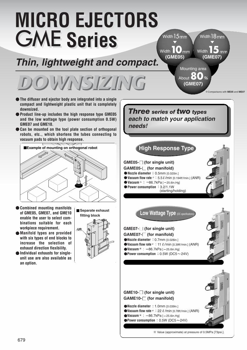
DOWNSIZINGThin, lightweight and compact.
The diffuser and ejector body are integrated into a singlecompact and lightweight plastic unit that is completelydownsized.Product line-up includes the high response type GME05and the low wattage type (power consumption 0.5W)GME07 and GME10.Can be mounted on the tool plate section of orthogonalrobots, etc., which shortens the tubes connecting tovacuum pads to obtain high response.
Combined mounting manifoldsof GME05, GME07, and GME10enable the user to select com-binations suitable for eachworkpiece requirement.Manifold types are providedwith six types of end blocks toincrease the selection ofexhaust direction flexibility.Individual exhausts for single-unit use are also available asan option.
Width15
Width10(GME05)
Mounting area
About 80(GME07)
Width18
Width15(GME07)
※Comparisons with ME05 and ME07
Example of mounting on orthogonal robot
DOWNSIZING
GME05- (for single unit)GAME05- (for manifold)
Nozzle diameter 0.5mm [0.020in.]
Vacuum flow rate 5.5R min [0.194ft.3/min.] (ANR)Vacuum 86.7kPa [ 25.6in.Hg]
Power consumption 3.2/1.1W(starting/holding)
GME07- (for single unit)GAME07- (for manifold)
Nozzle diameter 0.7mm [0.028in.]
Vacuum flow rate 11R min [0.39ft.3/min.] (ANR)Vacuum 86.7kPa [ 25.6in.Hg]
Power consumption 0.5W (DC5 24V)
GME10- (for single unit)GAME10- (for manifold)
Nozzle diameter 1.0mm [0.039in.]
Vacuum flow rate 22R min [0.78ft.3/min.] (ANR)Vacuum 86.7kPa [ 25.6in.Hg]
Power consumption 0.5W (DC5 24V)
※ Value (approximate) at pressure of 0.5MPa [73psi.].
High Response Type
Low Wattage Type (DC specifications)
-UR
Separate exhaustfitting block
Three series of two typeseach to match your applicationneeds!
680
Air Note2
0.9 [131]
5~50 [41~122]
0.7 [0.028]
-86.7 [-25.6]
11 [0.39]
23 [0.81]
Prohibited
30
Any
2 positions, 2 ports
Normally closed (NC standard)
2.3 [0.13]
1373 [140] (196 [20])
GME05-E1/GAME05-E1GME05-E2/GAME05-E2
GME07-E1/GAME07-E1GME07-E2/GAME07-E2
GME10-E1/GAME10-E1GME10-E2/GAME10-E2Item
Basic model
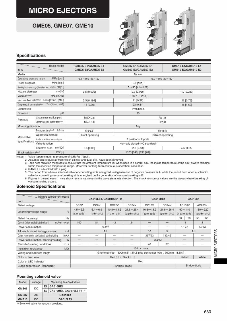
GME05, GME07, GME10
Specifications
Solenoid Specifications
Mounting solenoid valve
Notes: 1. Value (approximate) at pressure of 0.5MPa [73psi.].2. Assumes use of pure air from which oil mist and dust, etc., have been removed.3. Take heat radiation measures to ensure that the ambient temperature (or when used in a control box, the inside temperature of the box) always remains
within the specified temperature range. Moreover, for long-term continuous operation, consult us.4. GAME □ is blocked with a plug.5. The period from when a solenoid valve for controlling air is energized until generation of negative pressure is A, while the period from when a solenoid
valve for controlling vacuum breaking air is energized until a generation of vacuum breaking is B.6. Figures in parentheses ( ) are shock resistance values in the valve stem axis direction. The shock resistance values are the values where breaking of
vacuum holding occurs.
Media
Operating pressure range
Proof pressure
Operating temperature range (atmosphere and media)Note3
Nozzle diameter
VacuumNote1
Vacuum flow rateNote1
Compressed air consumptionNote1
Lubrication
Filtration
Port size
Mounting direction
Shock resistanceNote6
Vacuum generation port
Compressed air supply portNote4
Response timeNote5
Operation method
Number of positions, number of ports
Valve function
Effective area
MPa [psi.]
MPa [psi.]
°C [°F]
mm [in.]
kPa [in.Hg]
R/min [ft.3/min.] (ANR)
R/min [ft.3/min.] (ANR)
μm
A/B ms
mm2 [Cv]
m/s2 [G]
0.1~0.6 [15~87]
0.5 [0.020]
5.5 [0.194]
11 [0.39]
M5×0.8
M5×0.8
6.5/8.5
Direct operating
0.6 [0.03]
0.2~0.6 [29~87]
Rc1/8
Rc1/8
18/15.5
Indirect operating
1.0 [0.039]
22 [0.78]
46 [1.62]
4.5 [0.25]
Mounting solenoid valve models
Item
Rated voltage
Operating voltage range
Rated frequency
Current(when applied rated voltage)
Power consumption
Allowable circuit leakage current
Current (when applied rated voltage), starting/holding
Power consumption, starting/holding
Period of starting conditions
Insulation resistance
Wiring and lead wire length
Color of lead wire
Color of LED indicator
Surge suppression(standard)
DC5V
4.5~5.5
(5±10%)
―
100
―
―
―
DC6V
5.4~6.6
(6±10%)
―
84
―
―
―
DC12V
10.8~13.2
(12±10%)
―
42
―
―
―
DC24V
21.6~26.4
(24±10%)
―
21
―
―
―
DC12V
10.8~13.2
(12±10%)
―
―
―
10
267/92
48
DC24V
21.6~26.4
(24±10%)
―
―
―
5
133/46
27
AC100V
90~110
(100±10%)
11
1.1VA
―
―
―
Yellow
AC200V
180~220
(200±10%)
8
1.6VA
―
―
―
White
V
Hz
mA(r・m・s)
mA
m・A
W
m・s
MΩ
50 60 50 60
1.0
Bridge diode
Red(+), Black(-)
Flywheel diode
100 or more
Grommet type:300mm [11.8in.], plug connector type:300mm [11.8in.]
Red
0.5W
1.0
GA010LE1, GAV010LE1-11 GA010HE1 GA010E1
3.2/1.1
Model
GME05
GME07
GME10
Voltage
DC
AC
DC
Mounting solenoid valve
E1 GA010HE1
E2 GA010HE1, GAV010LE1-11※
GA010E1
GA010LE1
※Solenoid valve for vacuum breaking.
Main valve
specifications
MICRO EJECTORS
MIC
RO E
JECT
ORS
681
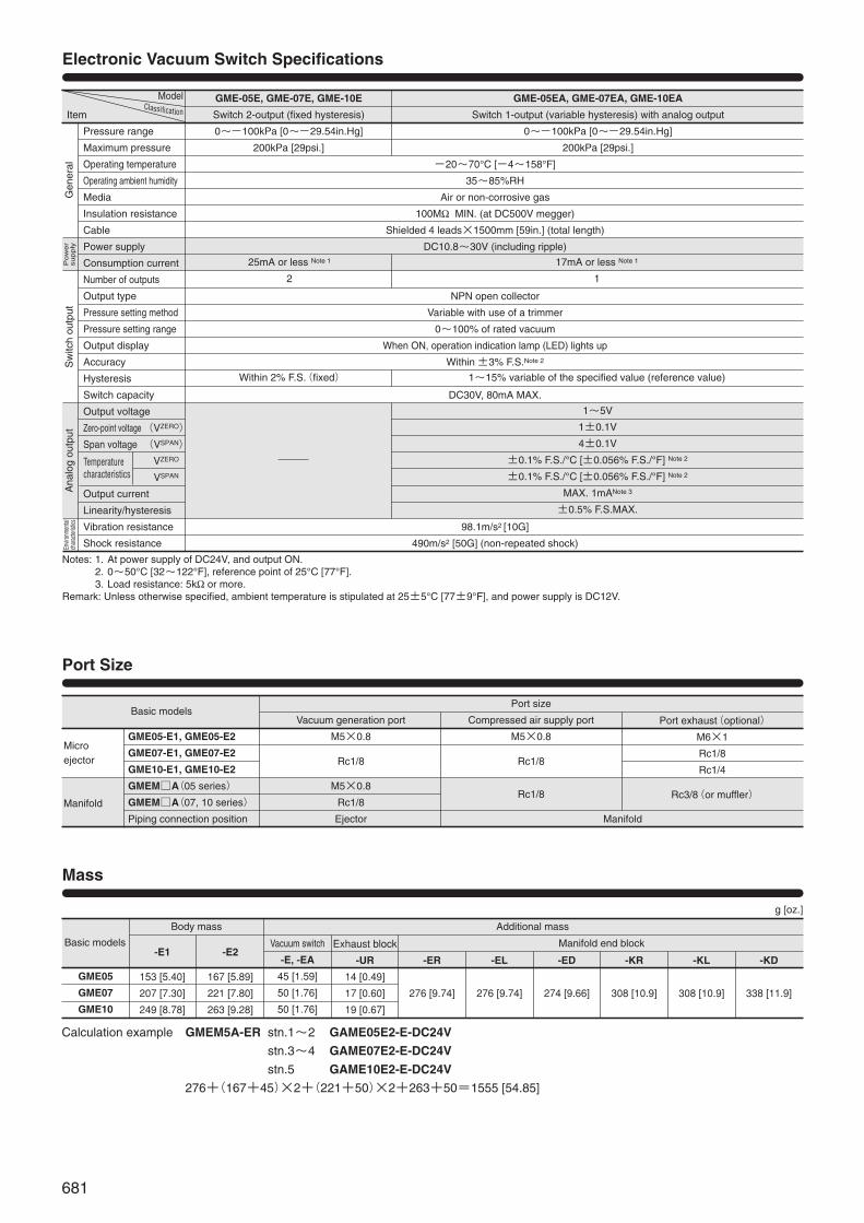
Port Size
Electronic Vacuum Switch Specifications
ModelClassiificationItem
Pressure range
Maximum pressure
Operating temperature
Operating ambient humidity
Media
Insulation resistance
Cable
Power supply
Consumption current
Number of outputs
Output type
Pressure setting method
Pressure setting range
Output display
Accuracy
Hysteresis
Switch capacity
Output voltage
Zero-point voltage
Span voltage
Output current
Linearity/hysteresis
Vibration resistance
Shock resistance
25mA or less Note 1
2
Within 2% F.S.(fixed)
17mA or less Note 1
1
1~15% variable of the specified value (reference value)
1~5V
1±0.1V
4±0.1V
±0.1% F.S./°C [±0.056% F.S./°F] Note 2
±0.1% F.S./°C [±0.056% F.S./°F] Note 2
MAX. 1mANote 3
±0.5% F.S.MAX.
Sw
itch
outp
utA
nalo
gou
tput
(VZERO)
(VSPAN)
VZERO
VSPAN
-20~70°C [-4~158°F]
35~85%RH
Air or non-corrosive gas
100MΩ MIN. (at DC500V megger)
Shielded 4 leads×1500mm [59in.] (total length)
DC10.8~30V (including ripple)
NPN open collector
Variable with use of a trimmer
0~100% of rated vacuum
When ON, operation indication lamp (LED) lights up
Within ±3% F.S.Note 2
DC30V, 80mA MAX.
98.1m/s2 [10G]
490m/s2 [50G] (non-repeated shock)
GME-05E, GME-07E, GME-10E
Switch 2-output (fixed hysteresis)
0~-100kPa [0~-29.54in.Hg]
200kPa [29psi.]
GME-05EA, GME-07EA, GME-10EA
Switch 1-output (variable hysteresis) with analog output
0~-100kPa [0~-29.54in.Hg]
200kPa [29psi.]
Notes: 1. At power supply of DC24V, and output ON.2. 0~50°C [32~122°F], reference point of 25°C [77°F].3. Load resistance: 5kΩ or more.
Remark: Unless otherwise specified, ambient temperature is stipulated at 25±5°C [77±9°F], and power supply is DC12V.
Microejector
Manifold
GME05-E1, GME05-E2
GME07-E1, GME07-E2
GME10-E1, GME10-E2
GMEM□A(05 series)
GMEM□A(07, 10 series)
Piping connection position
Basic models
Basic models
Port size
Compressed air supply port
M5×0.8
Rc1/8
Rc1/8
Manifold
Vacuum generation port
M5×0.8
Rc1/8
M5×0.8
Rc1/8
Ejector
Port exhaust(optional)
M6×1
Rc1/8
Rc1/4
Rc3/8(or muffler)
Mass
GME05
GME07
GME10
Body mass Additional mass
Manifold end block-E1
153 [5.40]
207 [7.30]
249 [8.78]
-E2
167 [5.89]
221 [7.80]
263 [9.28]
Vacuum switch
-E, -EA
45 [1.59]
50 [1.76]
50 [1.76]
Exhaust block
-UR
14 [0.49]
17 [0.60]
19 [0.67]
-ER
276 [9.74]
-EL
276 [9.74]
-ED
274 [9.66]
-KR
308 [10.9]
-KL
308 [10.9]
-KD
338 [11.9]
Calculation example GMEM5A-ER stn.1~2 GAME05E2-E-DC24V
stn.3~4 GAME07E2-E-DC24V
stn.5 GAME10E2-E-DC24V
276+(167+45)×2+(221+50)×2+263+50=1555 [54.85]
g [oz.]
Gen
eral
Pow
er
supply
Envir
onme
ntal
chara
cteris
tics
Temperaturecharacteristics

682
Ejector with Solenoid Valve Order Codes Manifold Order Codes
Electronic Vacuum Switch Order Codes
Additional Stacking Unit Order Codes (for adding one unit when using manifolds)
Replacement Filter Order Codes (element only)
GMEM A
GAME
VoltageNote2
DC5VDC6VDC12VDC24VAC100VAC200V
SolenoidBlank GrommetPL L connector, positive commonML L connector, negative common
Lead wire lengthBlank 300mm [11.8in.]1L 1000mm [39in.]
(Connector type only)3L 3000mm [118in.]
(Connector type only)
Number of unitsNote 1
2 Two units3 Three units… …5 Five units
End block typeER Exhaust port on right sideEL Exhaust port on left sideED Exhaust ports on both sidesKR Muffler on right sideKL Muffler on left sideKD Mufflers on both sides
Station(the ejector mounting positionsare listed from the left with thevacuum generation port infront)Stn.1 Station 1Stn.2 Station 2… …
Stn.5 Station 5
Manifold basic model
A-type manifold
Micro ejector model
Electronic vacuum switchBlank No vacuum switch
E With 2-output type vacuum switchEA With 1-output type vacuum switch
Exhaust method (for selection of GME type only)Blank Muffler exhaust
UR Port exhaust
Solenoid valve specificationE1 Single solenoid valve for controlling supply air E2 Twin solenoid valves for controlling supply air and vacuum breaking air
Body type (nozzle diameter: mm)05 φ0.5 [0.020in.]07 φ0.7 [0.028in.]10 φ1.0 [0.039in.]
Micro ejectorGME For single-unitGCME For additional stacking unitGAME For manifold
Electronic vacuum switchfor micro ejector
05(for 05)07(for 07, 10)
For manifoldmounting
See ejector with solenoid valve order codeNotes: 1. Since manifolds of six or more units require a special modifi-
cation, consult us for delivery times and prices.2. Voltage for the GME05 series is limited to DC12V and DC24V. As the
mounted solenoid valves vary according to the series, see the tablebelow, and confirm it against the solenoid specifications on p.680.
GME
05 For GME0507 For GME0710 For GME10
Type (See ejector with solenoid valve order codes, andmake full entries from body type to voltage)
Additional stacking unit model
In addition to one manifold use ejector (GCME...), the additional stacking unit includestwo stacking rods, one gasket, and one O-ring.
(Supplied items: one base, two spacers, two hexagon socket screws)
GCME
GME F
Mounting Base Order Code (for direct piping type)
GME-21
Muffler Order Codes (only for manifolds)
GMEM-KM
Model
GME05
GME07
GME10
Voltage
DC
AC
DC
Mounting solenoid valve
E1 GA010HE1
E2 GA010HE1, GAV010LE1-11※
GA010E1
GA010LE1
※Solenoid valve for controlling vacuum breaking air.
Switch specificationE Switch 2-output typeEA Switch 1-output type
R ───Muffler on right sideL ───Muffler on left side
(one pack five pcs.)
MIC
RO E
JECT
ORS
683
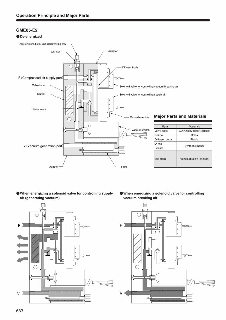
Aluminum alloy (painted)End block
Aluminum alloy (painted) and plastic
BrassNozzle
PlasticDiffuser body
Synthetic rubberO-ring
Gasket
Major Parts and Materials
Materials
Valve base
Parts
Operation Principle and Major Parts
●De-energized
●When energizing a solenoid valve for controlling supply air (generating vacuum)
●When energizing a solenoid valve for controlling vacuum breaking air
P(Compressed air supply port)
V(Vacuum generation port)
-02
-ML;エルコネクタ ・マイナスコモン
-PL;エルコネクタ ・プラスコモン
基本形式 GME 05-E2
P
VL
L
GME05-E2-1
10.5
41
43
40
42
Valve base
Lock nut
Adjusting needle for vacuum breaking flow
Adapter
Diffuser body
Solenoid valve for controlling supply air
Solenoid valve for controlling vacuum breaking air
Vacuum switch
FilterAdapter
Check valve
Manual override
Muffler
P
V
GME05-E2-1
P
V
GME05-E2-1
GME05-E2
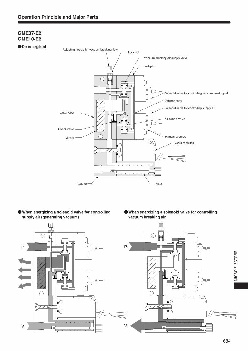
684
Operation Principle and Major Parts
Valve base
Lock nutAdjusting needle for vacuum breaking flow
Adapter
Air supply valve
Vacuum breaking air supply valve
Diffuser body
Solenoid valve for controlling supply air
Vacuum switch
FilterAdapter
Check valve
Manual override
Solenoid valve for controlling vacuum breaking air
Muffler
P
V
P
V
●De-energized
●When energizing a solenoid valve for controllingsupply air (generating vacuum)
●When energizing a solenoid valve for controlling vacuum breaking air
GME07-E2GME10-E2
MIC
RO E
JECT
ORS
685
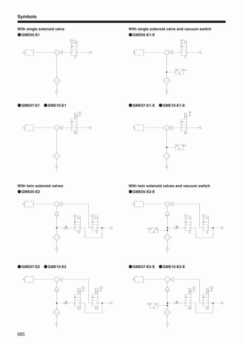
Symbols
With single solenoid valve
●GME05-E1
With single solenoid valve and vacuum switch
●GME05-E1-E
With twin solenoid valves
●GME05-E2
With twin solenoid valves and vacuum switch
●GME05-E2-E
●GME07-E1 ●GME10-E1 ●GME07-E1-E ●GME10-E1-E
●GME07-E2 ●GME10-E2 ●GME07-E2-E ●GME10-E2-E

686
Dimensions (mm)
(Mounting hole)
形式 GME05-E2-□
GME05-E2-1Y
MAX.12.4
MIN.10
7.9
9.9
Muffler
Filter
2-φ4.6
46.5
PD
B
M
E point
67.5
79
C
Adjusting needle for vacuum breaking flow
-E,-EA
Electronic vacuumswitch
V
6.5
K
2-K
L
J
I
QR
(V: Vacuum generation port)
(P: Compressed air supply port)
Solenoid valve for controllingvacuum breaking air
Manual override
Solenoid valve for controllingsupply air
FG
H
L
L
●GME□-E1,E2
●-PL,-ML
●-UR
●-21
Model
GME05-E□
GME07-E□
GME10-E□
B
64.1
67.0
67.0
C
118
118
128
D
75
75
75
F
75
75
85
G
20
25
25
H
23
18
18
I
10.5
15.5
18.5
J
5.25
7.75
9.25
K
M5×0.8
Rc1/8
Rc1/8
L
4.25
5.75
9.25
M
17.5
18.5
18.5
P
11
11
21
Q
87.5
93.0
95.0
R
13
8
8
Options
GME05-E2-□-02-□ 形式
GME05-E2-3Y
P
V
T
U
Fitting block
W
S
(R: Exhaust port)
t=1.6
(R2)
9
61.6
28
2-φ4.5
15
M3×0.5
4 3
37.5
127
GME05-E□:74.7 GME07-E□:77.2 GME10-E□:77.2
E point
Model
GME05-E□
GME07-E□
GME10-E□
S
8
10
10
T
15
20
23
U
70.8
70.8
70.8
W
M6×1
Rc1/8
Rc1/4
GME□
MIC
RO E
JECT
ORS
687
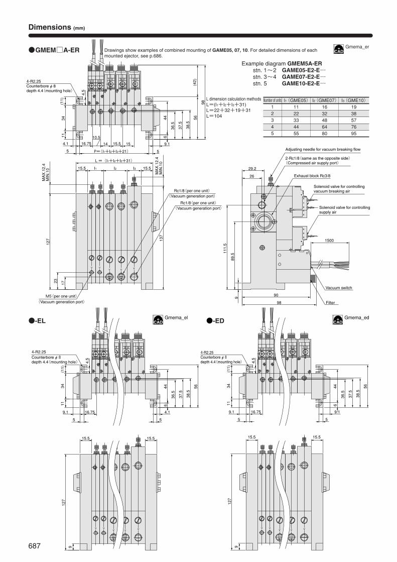
L dimension calculation methodsL=(l1+l2+l3+31)L=22+32+19+31L=104
Dimensions (mm)
4-R2.25 Counterbore φ 8 depth 4.4(mounting hole)
1515.514
10.5
16.75
26
29.2
90
98
5
11(11)
5
6
36.5
37.5
38.5
56(42)
98
9.1
89.5
Solenoid valve for controllingsupply air
Solenoid valve for controlling vacuum breaking air
1500
Filter
Vacuum switch
111.5
Adjusting needle for vacuum breaking flow
2-Rc1/8(same as the opposite side) (Compressed air supply port)
Exhaust block Rc3/8
P=(I1+I2+I3+21)
34 44
4.1
9
4.5
VVVVV
MAX.12.4
MIN.10
MAX.12.4
MIN.10
15.515.5
L=(I1+I2+I3+31) 137
1723
127
I1 I2 I3
M5(per one unit) (Vacuum generation port)
Rc1/8(per one unit) (Vacuum generation port)
Rc1/8(per one unit) (Vacuum generation port)
●GMEM□A-ER
●-EL
Number of units12345
l1(GME05)1122334455
l2(GME07)1632486480
l3(GME10)1938577695
VVVVV
16.75
36.5
37.5
38.5
6
56
55
(11)
11
9.1
15.515.5
127
34 44
4.1
9
4.5
4-R2.25 Counterbore φ 8 depth 4.4(mounting hole)
●-ED
VVVVV
9
4.5
16.75
36.5
37.5
38.5
6
56
55
(11)
11
9.1
34 44
9.1
15.515.5
127
4-R2.25 Counterbore φ 8 depth 4.4(mounting hole)
Drawings show examples of combined mounting of GAME05, 07, 10. For detailed dimensions of eachmounted ejector, see p.686.
Example diagram GMEM5A-ERstn. 1~2 GAME05-E2-E…stn. 3~4 GAME07-E2-E…stn. 5 GAME10-E2-E…
Gmema_er
Gmema_edGmema_el
688
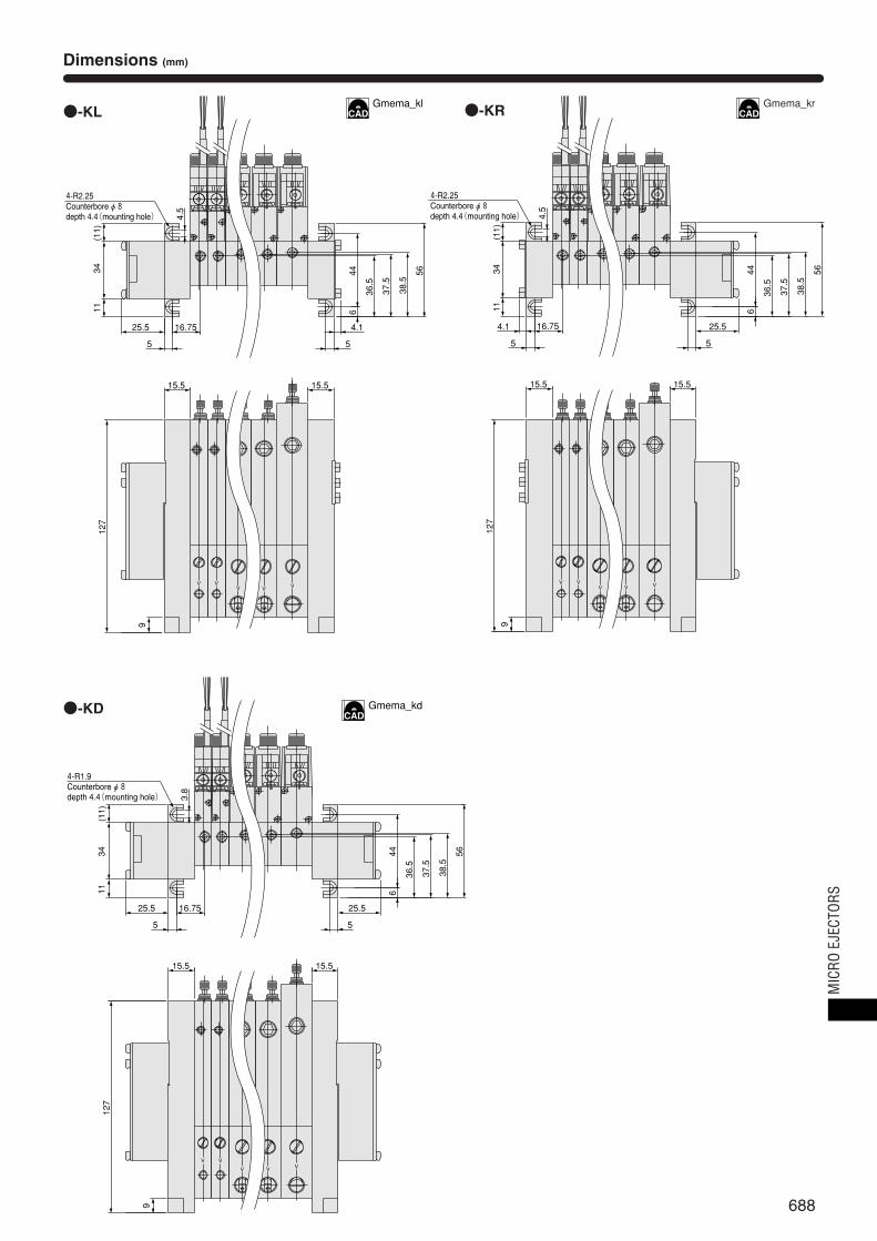
Dimensions (mm)
●-KL
VVVVV
16.75
11(11)
6
36.5
37.5
38.5
56
5
25.5
34
5
15.515.5
127
44
4.1
9
4-R2.25 Counterbore φ 8 depth 4.4(mounting hole) 4.
5
●-KD
VVV
VV
16.75
611(11)
5
36.5
37.5
38.5
56
5
25.525.5
34
15.515.5
127
44
9
4-R1.9 Counterbore φ 8 depth 4.4(mounting hole) 3.
8
●-KR
VVVVV
16.75
5
6
36.5
37.5
38.5
56
5
11(11)
25.5
15.515.5
127
34 44
4.1
9
4-R2.25 Counterbore φ 8 depth 4.4(mounting hole) 4.
5
Gmema_krGmema_kl
Gmema_kd
MIC
RO E
JECT
ORS
689
Handling Instructions and Precautions
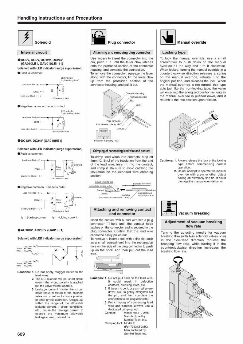
Solenoid
Internal circuit
●DC5V, DC6V, DC12V, DC24V (GA010LE1, GAV010LE1-11)
Solenoid with LED indicator (surge suppression)
Plug connector
Attaching and removing plug connector
Manual override
Use fingers to insert the connector into thepin, push it in until the lever claw latchesonto the protruded section of the connectorhousing, and complete the connection.To remove the connector, squeeze the leveralong with the connector, lift the lever clawup from the protruded section of theconnector housing, and pull it out.
Locking type
To lock the manual override, use a smallscrewdriver to push down on the manualoverride all the way and turn it clockwise.When locked, turning the manual override in acounterclockwise direction releases a springon the manual override, returns it to theoriginal position, and releases the lock. Whenthe manual override is not turned, this typeacts just like the non-locking type, the valvewill enter into the energized position as long asthe manual override is pushed down, and itreturns to the rest position upon release.
Crimping of connecting lead wire and contact
To crimp lead wires into contacts, strip off4mm [0.16in.] of the insulation from the endof the lead wire, insert it into the contact,and crimp it. Be sure to avoid catching theinsulation on the exposed wire crimpingsection.
Attaching and removing contactand connector
Insert the contact with a lead wire into a plugconnector □ hole until the contact hooklatches on the connector and is secured to theplug connector. Confirm that the lead wirecannot be easily pulled out.To remove it, insert a tool with a fine tip(suchas a small screwdriver)into the rectangularhole on the side of the plug connector to pushup on the hook, and then pull out the leadwire.
Cautions: 1. Do not apply megger between thelead wires.
2. The DC solenoid will not short circuiteven if the wrong polarity is applied,but the valve will not operate.
3. Leakage current inside the circuitcould result in failure of the solenoidvalve not to return to home positionor other erratic operation. Always usewithin the range of the allowableleakage current. If circuit conditions,etc., cause the leakage current toexceed the maximum allowableleakage current, consult us.
Contact
Lever
Plug connector
Indication of polarity(DC)
Indication of polarity(DC)
Protruded section
Pin
Connector housing
+ C-
Hook
Exposed wire crimping section
Insulation crimp tab
Contact
Exposed wire 4mm
Lead wire
Insulation(Maximum outer diameter:φ1.5)
Applicable wire AWG#24~#30
PUSH
TURN
LED indicator(Light emitting diode)
LED indicator: Red
Lead wire: Red
Lead wire: Black
(+)
(-)
(COM)
(COM)
LED indicator(Light emitting diode)
LED indicator: Red
Lead wire: Red
Lead wire: Black
(+)
(-)
(AC)
(AC)
(COM)
Lead wire
Lead wire
Yellow:AC100V White :AC200V
Yellow:AC100V White :AC200V
●AC100V, AC200V (GA010E1)
Solenoid with LED indicator (surge suppression)
●Positive common
●Negative common(made to order)
●DC12V, DC24V (GA010HE1)
Solenoid with LED indicator (surge suppression)
LED indicator: Red
Timercircuit
ia
is
Lead wire: Red
Lead wire: Black
(+)
(-)
(COM)
Solenoid
ia
is
(COM)
LED indicator: Red
Timercircuit
Lead wire: Red
Lead wire: Black
(+)
(-)
Solenoid
●Positive common
●Negative common (made to order)
ia:Starting current is:Holding current
Adjustment of vacuum breaking flow rate
Turning the adjusting needle for vacuumbreaking flow (with twin solenoid valves only)in the clockwise direction reduces thebreaking flow rate, while turning it in thecounterclockwise direction increases thebreaking flow rate.
Vacuum breaking
Cautions: 1. Do not pull hard on the lead wire.It could result in defectivecontacts, breaking wires, etc.
2. If the pin is bent, use a small screw-driver, etc., to gently straighten outthe pin, and then complete theconnection to the plug connector.
3. For crimping of connecting leadwire and contact, always use adedicated crimping tool.
Contact: Model 706312-2MKManufactured by Sumiko Tech, Inc.
Crimping tool: Model FI (For 706312-2MK)Manufactured by Sumiko Tech, Inc.
Cautions: 1. Always release the lock of the lockingtype before commencing normaloperation.
2. Do not attempt to operate the manualoverride with a pin or other objecthaving an extremely fine tip. It coulddamage the manual override button.
690
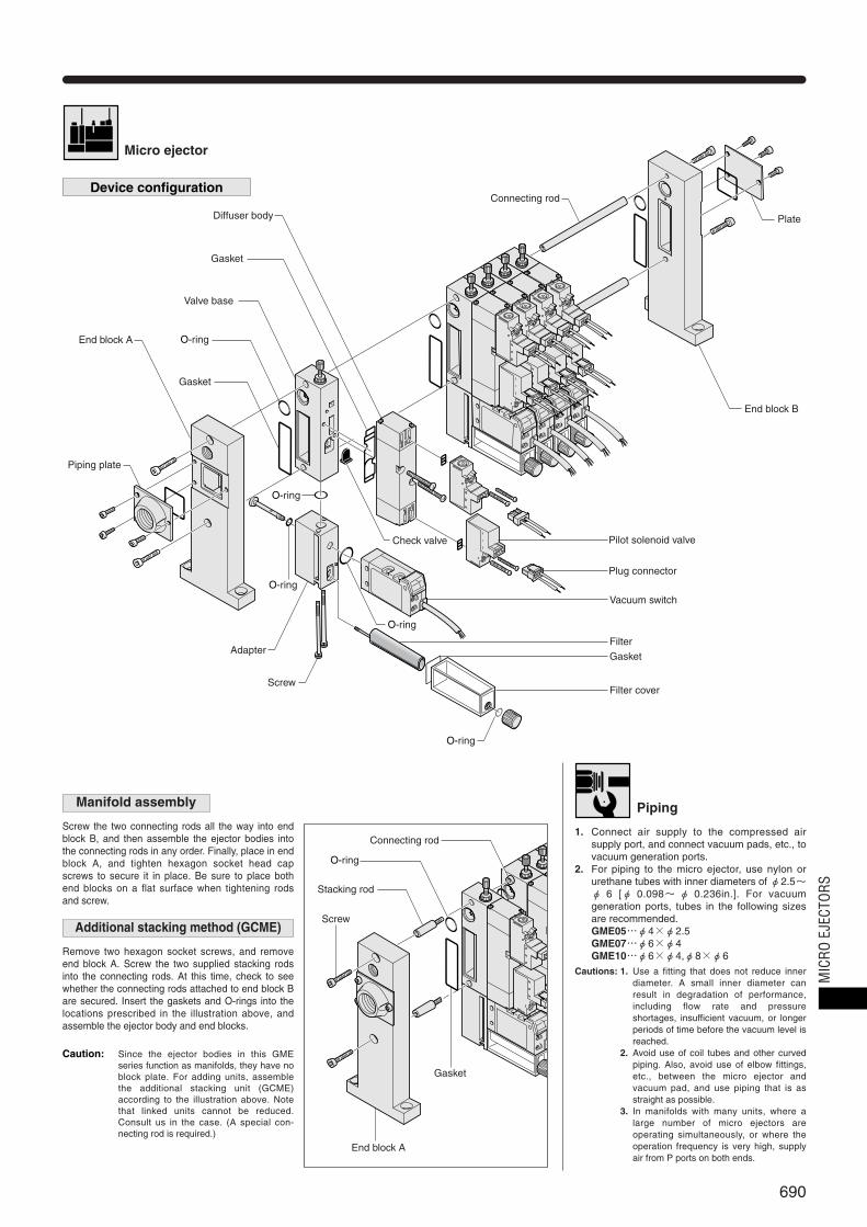
Micro ejector
Device configuration
Caution: Since the ejector bodies in this GMEseries function as manifolds, they have noblock plate. For adding units, assemblethe additional stacking unit (GCME)according to the illustration above. Notethat linked units cannot be reduced.Consult us in the case. (A special con-necting rod is required.)
Piping plate
Plate
Vacuum switch
Filter cover
Gasket
FilterAdapter
Screw
Check valve
End block B
Plug connector
Pilot solenoid valve
O-ring
End block A
Connecting rod
Gasket
O-ring
O-ring
O-ring
O-ring
Valve base
Gasket
Diffuser body
Manifold assembly
Screw the two connecting rods all the way into endblock B, and then assemble the ejector bodies intothe connecting rods in any order. Finally, place in endblock A, and tighten hexagon socket head capscrews to secure it in place. Be sure to place bothend blocks on a flat surface when tightening rodsand screw.
Additional stacking method (GCME)
Remove two hexagon socket screws, and removeend block A. Screw the two supplied stacking rodsinto the connecting rods. At this time, check to seewhether the connecting rods attached to end block Bare secured. Insert the gaskets and O-rings into thelocations prescribed in the illustration above, andassemble the ejector body and end blocks.
O-ring
Stacking rod
Screw
Gasket
End block A
Connecting rod
Cautions: 1. Use a fitting that does not reduce innerdiameter. A small inner diameter canresult in degradation of performance,including flow rate and pressureshortages, insufficient vacuum, or longerperiods of time before the vacuum level isreached.
2. Avoid use of coil tubes and other curvedpiping. Also, avoid use of elbow fittings,etc., between the micro ejector andvacuum pad, and use piping that is asstraight as possible.
3. In manifolds with many units, where alarge number of micro ejectors areoperating simultaneously, or where theoperation frequency is very high, supplyair from P ports on both ends.
1. Connect air supply to the compressed airsupply port, and connect vacuum pads, etc., tovacuum generation ports.
2. For piping to the micro ejector, use nylon orurethane tubes with inner diameters of φ2.5~φ 6 [φ 0.098~ φ 0.236in.]. For vacuumgeneration ports, tubes in the following sizesare recommended.GME05…φ4×φ2.5GME07…φ6×φ4GME10…φ6×φ4,φ8×φ6
PipingM
ICRO
EJE
CTOR
S
691
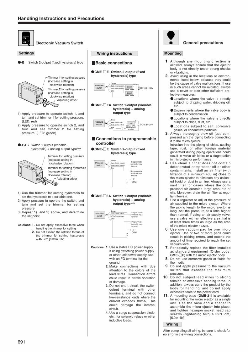
Electronic Vacuum Switch
Wiring instructions
Trimmer 1 for setting pressure (increase setting in clockwise rotation)
Trimmer 2 for setting pressure (increase setting in clockwise rotation)
Adjusting driver
Trimmer for setting pressure(increase setting in clockwise rotation)
Trimmer for setting hysteresis (increase setting in clockwise rotation)
Adjusting driver
Settings
●-E: Switch 2-output (fixed hysteresis) type
●-EA: Switch 1-output (variable hysteresis) + analog output typeNote
1) Apply pressure to operate switch 1, and turn and set trimmer 1 for setting pressure.(LED: red)
2) Apply pressure to operate switch 2, andturn and set trimmer 2 for settingpressure. (LED: green)
1) Use the trimmer for setting hysteresis toset the hysteresis to a suitable one.
2) Apply pressure to operate the switch, andturn and set the trimmer for settingpressure.
3) Repeat 1) and 2) above, and determinethe set point.
Pressureswitch
BrownBlack Switch output 1
80mA MAX.
80mA MAX.
White Switch output 2
BlueLoad
Load DC10.8~30V
BrownBlack Switch output
80mA MAX.White Analog output
Measurementamplifier
Blue
Load DC10.8~30VPressure
switch
(+)
Programmablecontroller inputterminal
Programmablecontroller inputterminal
Pressureswitch
BrownBlack Switch output 1
White Switch output 2
Blue
COM.
(+)
Programmablecontroller inputterminal
Programmablecontroller inputterminal
Pressureswitch
BrownBlack Switch output
White Analog output
Blue
COM.
●GME-□E Switch 2-output (fixedhysteresis) type
Basic connections
Connections to programmablecontroller
●GME-□EA Switch 1-output (variablehysteresis) + analogoutput type
●GME-□E Switch 2-output (fixedhysteresis) type
●GME-□EA Switch 1-output (variablehysteresis) + analogoutput typeNote
Cautions: 1. Do not apply excessive force whenhandling the trimmer for setting.
2. Do not exceed the rotation torque ofthe trimmer for setting hysteresis4.4N・cm [0.39in・lbf].
Cautions: 1. Use a stable DC power supply.If using switching power supplyor other unit power supply, usewith an FG terminal for theground.
2. Make connections with dueattention to the colors of thelead wires. Connection errorscould result in erratic operationor damage.
3. Do not short-circuit the switchoutput terminal with otherterminals, and do not connectlow-resistance loads where thecurrent exceeds 80mA. Thiscould damage the internalcircuit.
4. Use a surge suppression diode,etc., for solenoid relays or otherinductive loads.
General precautions
Mounting
1. Although any mounting direction isallowed, always ensure that the ejectorbody is not directly under strong shocksor vibrations.
2. Avoid using in the locations or environ-ments listed below, because they couldbe the cause of valve malfunctions. If usein such areas cannot be avoided, alwaysuse a cover or take other sufficient pro-tective measures.●Locations where the valve is directly
subject to dripping water, dripping oil,etc.
●Environments where the valve body issubject to condensation
●Locations where the valve is directlysubject to chips, dust, etc.
●Locations subject to salt, corrosivegases, or conductive particles
3. Always thoroughly blow off (use com-pressed air) the piping before connectingit to the micro ejector. Intrusion into the piping of chips, sealingtape, rust, or other foreign materialgenerated during piping operations couldresult in valve air leaks or a degradationin micro ejector performance.
4. Use clean air that does not contain deteriorated compressor oil or other contaminants. Install an air filter (with filtration of a minimum 40μm) close tothe micro ejector to eliminate any collect-ed liquid or dust in air line. Always use amist fi lter for cases where the com-pressed air contains large amounts ofoils. Moreover, drain the air filter at regu-lar intervals.
5. Use a regulator to adjust the pressure ofair supplied to the micro ejector. Wherethe piping length to the micro ejector islong, set the pressure at a little higherthan normal. If using an air supply valve,use a valve with an effective area that isat least three times as large as the areaof the micro ejector nozzle.
6. Use one vacuum pad for one micro ejector. Use of two or more pads couldresult in picking errors, and extend theamount of time required to reach the setvacuum level.
7. Periodically replace the filter installed as standard equipment (Order code:GME-□F) with the micro ejector body.
8. Do not use corrosive gases or fluids forthe media.
9. Do not apply pressure to the vacuumswitch that exceeds the maximum pressure.
10. Do not subject lead wires to strong tension or excessive bending force. Inaddition, always carry the product by thebody for handling, and do not applyexcessive force to the power cord.
11. A mounting base (GME-21) is availablefor mounting the micro ejector as a singleunit. Use the base and a spacer toassemble the micro ejector into place,and tighten hexagon socket head capscrews {t ightening torque 59N・cm}[5.2in・lbf].
Wiring
After completing all wiring, be sure to check forno error in the wiring connections.
Handling Instructions and Precautions
692
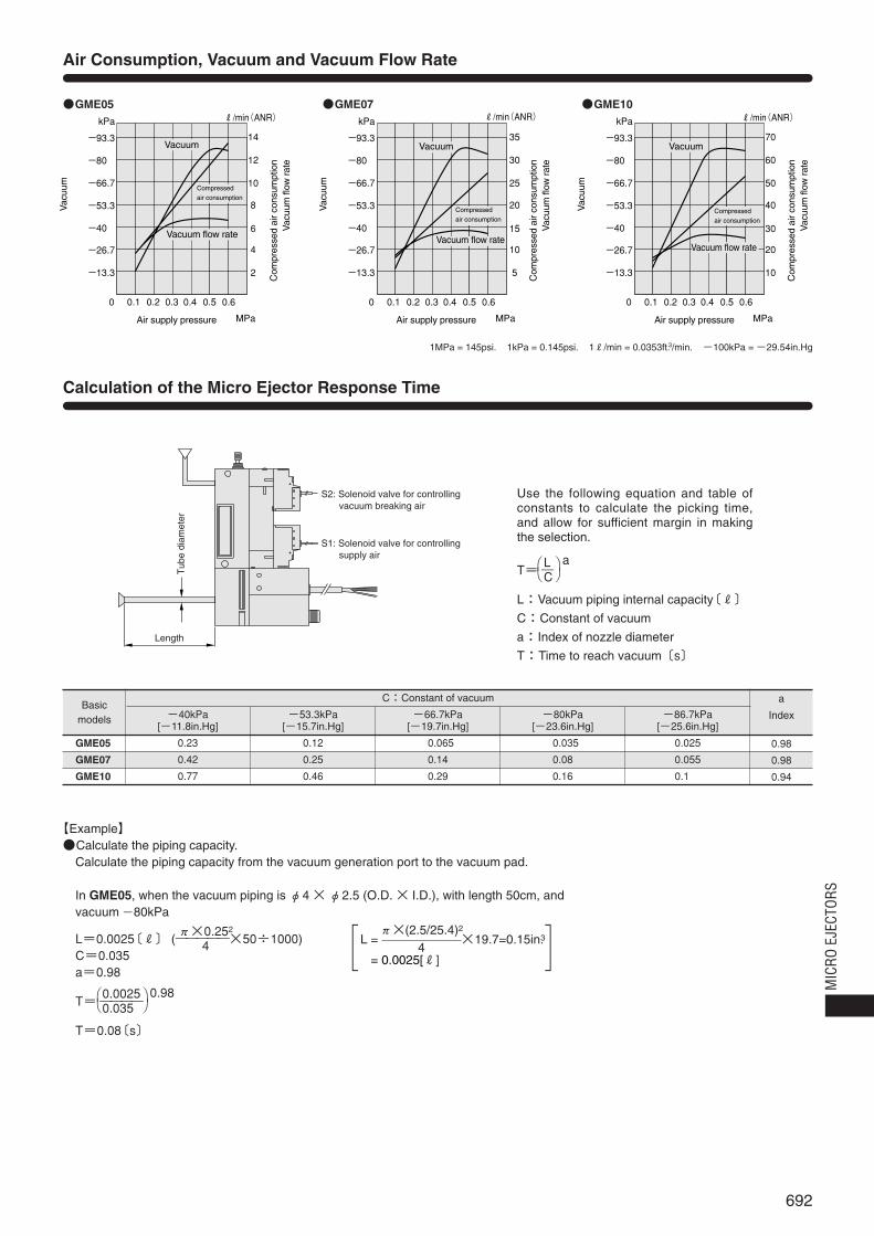
Air Consumption, Vacuum and Vacuum Flow Rate
Calculation of the Micro Ejector Response Time
●GME05 ●GME07 ●GME10
-40kPa[-11.8in.Hg]
0.23
0.42
0.77
-53.3kPa[-15.7in.Hg]
0.12
0.25
0.46
-66.7kPa[-19.7in.Hg]
0.065
0.14
0.29
-80kPa[-23.6in.Hg]
0.035
0.08
0.16
-86.7kPa[-25.6in.Hg]
0.025
0.055
0.100
a
Index
0.98
0.98
0.94
Basicmodels
C:Constant of vacuum
GME05
GME07
GME10
Use the following equation and table ofconstants to calculate the picking time,and allow for sufficient margin in makingthe selection.
T= ―
L:Vacuum piping internal capacity〔R〕C:Constant of vacuum
a:Index of nozzle diameter
T:Time to reach vacuum〔s〕
LC
⎛ ⎞ a⎝ ⎠
S2: Solenoid valve for controlling vacuum breaking air
S1: Solenoid valve for controllingsupply air
Length
Tub
e di
amet
er
0
5
10
15
20
25
30
35
0.1 0.2 0.3 0.4 0.5 0.6
MPa
R/min(ANR)
0
10
20
30
40
50
60
70
0.1 0.2 0.3 0.4 0.5 0.6
MPa
R/min(ANR)
0
ー13.3
ー26.7
ー40.3
ー53.3
ー66.7
ー80.3
ー93.3
kPa
ー13.3
ー26.7
ー40.3
ー53.3
ー66.7
ー80.3
ー93.3
kPa
ー13.3
ー26.7
ー40.3
ー53.3
ー66.7
ー80.3
ー93.3
kPa
2
4
6
8
10
12
14
0.1 0.2 0.3 0.4 0.5 0.6
MPa
R/min(ANR)
Vacuum flow rate
Vac
uum
Vacuum
Air supply pressure
Compressedair consumption
Vac
uum
flow
rat
eC
ompr
esse
d ai
r co
nsum
ptio
n
Vacuum flow rateVacuum flow rate
Vac
uum
Vacuum
Air supply pressure
Compressedair consumption
Vac
uum
flow
rat
eC
ompr
esse
d ai
r co
nsum
ptio
n
Vac
uum
Vacuum
Air supply pressure
Compressedair consumption
Vac
uum
flow
rat
eC
ompr
esse
d ai
r co
nsum
ptio
n
【Example】●Calculate the piping capacity.
Calculate the piping capacity from the vacuum generation port to the vacuum pad.
In GME05, when the vacuum piping is φ4 ×φ2.5 (O.D. × I.D.), with length 50cm, andvacuum -80kPa
L=0.0025〔R〕 (―――――×50÷1000)C=0.035a=0.98
T= ――――
T=0.08〔s〕
0.00250.035
⎛ ⎞ 0.98⎝ ⎠
π×0.2524
1MPa = 145psi. 1kPa = 0.145psi. 1R/min = 0.0353ft.3/min. -100kPa = -29.54in.Hg
L = ×19.7=0.15in.3
L = 0.0025[R]
π×(2.5/25.4)2
4[ ]
MIC
RO E
JECT
ORS
693
ME03□ME03-E1
ME05□ME05-E1
AME05-E2ME07
□ME07-E1AME07-E2
Basic modelItem
Operating pressure range MPa [psi.] 0.1~0.6[15~87]
0.1~0.6[15~87]
0.2~0.6[29~87]
0.1~0.6[15~87]
0.2~0.6[29~87]
Air
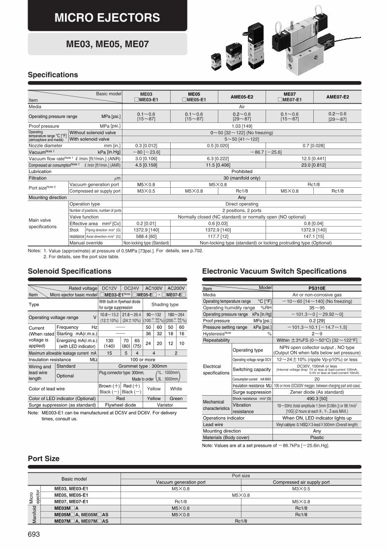
ME03, ME05, ME07
Specifications
Notes: 1. Value (approximate) at pressure of 0.5MPa [73psi.]. For details, see p.702.2. For details, see the port size table.
Proof pressure MPa [psi.] 1.03 [149]
Nozzle diameter mm [in.] 0.3 [0.012] 0.5 [0.020]VacuumNote 1 kPa [in.Hg] ー80 [ー23.6] ー86.7 [ー25.6]Vacuum flow rateNote 1 R/min [ft.3/min.] (ANR) 3.0 [0.106] 6.3 [0.222] 12.5 [0.441]Compressed air consumptionNote 1 R/min [ft.3/min.] (ANR) 4.5 [0.159] 11.5 [0.406] 23.0 [0.812]Lubrication Prohibited
30 (manifold only)Filtration μm
AnyMounting direction
M5×0.8 M5×0.8 Rc1/8M3×0.5 M5×0.8 Rc1/8 M5×0.8 Rc1/8
Port sizeNote 2Vacuum generation portCompressed air supply port
Direct operating2 positions, 2 ports
Normally closed (NC standard) or normally open (NO optional)0.2 [0.01] 0.6 [0.03] 0.8 [0.04]
1372.9 [140] 1372.9 [140] 1372.9 [140]588.4 [60] 117.7 [12]
Non-locking type (Standard) Non-locking type (standard) or locking protruding type (Optional)147.1 [15]
Main valvespecifications
Number of positions, number of ports
Valve functionEffective area mm2 [Cv]
Manual override
Shockresistance
Piping direction m/s2 [G]
Axial direction m/s2 [G]
Operation type
0.7 [0.028]
Operating temperature range °C [°F](atmosphere and media)
Without solenoid valveWith solenoid valve
0~50 [32~122] (No freezing)5~50 [41~122]
Media
Solenoid Specifications
DC12V□ME03-E1Note □ME05-E□・□ME07-E□
DC24V AC100V AC200VRated voltageItem Micro ejector basic model
Note: ME003-E1 can be manufactured at DC5V and DC6V. For deliverytimes, consult us.
Type
Operating voltage range V
Current(When ratedvoltage isapplied)
Maximum allowable leakage current mA
Frequency Hz 6050 50 603236 18 16
130(140)
15Insulation resistance MΩWiring and lead wirelength
Standard
Optional
100 or moreGrommet type : 300mm
Plug connector type: 300mm, Made to order
Color of lead wireBrown (+)Black (ー)
Color of LED indicator (Optional) Red Yellow GreenSurge suppression (as standard) Flywheel diode Varistor
Red (+)Black (ー)
Yellow White
5 4 4 2
70(80)
65(75) 24 20 12 10
Starting mA(r.m.s.)
Energizing mA(r.m.s.)(with LED indicator)
With built-in flywheel diodefor surge suppression
10.8~13.2(12±10%)
21.6~26.4(24±10%)
90~132(100 %)
180~264(200 %)
Shading type
( )
Port Size
Port sizeVacuum generation port Compressed air supply port
Basic model
Mic
roej
ecto
rM
anifo
ld
ME03, ME03-E1 M5×0.8 M3×0.5M5×0.8
Rc1/8 M5×0.8M5×0.8 Rc1/8M5×0.8 Rc1/8
Rc1/8
ME05, ME05-E1ME07, ME07-E1ME03M□AME05M□A, ME05M□ASME07M□A, ME07M□AS
MICRO EJECTORS
+32-10
+32-10
1L : 1000mm3L : 3000mm
Electronic Vacuum Switch Specifications
PS310EAir or non-corrosive gas
Item Model
Note: Values are at a set pressure of ー86.7kPa [ー25.6in.Hg].
Mediaー10~60 [14~140] (No freezing)Operating temperature range °C [°F]
35~95Operating humidity range %RHー101.3~0 [ー29.92~0]Operating pressure range kPa [in.Hg]
0.2 [29]Proof pressure MPa [psi.]ー101.3~10.1 [ー14.7~1.5]Pressure setting range kPa [psi.]
2~9HysteresisNote %Within ±3%FS (0~50°C) [32~122°F]
NPN open collector output , NO type(Output ON when falls below set pressure)
12~24±10% (ripple Vp-p10%) or lessDC30V, 100mA or less
(Internal voltage drop: 1V or less at load current 100mA, 0.4V or less at load current 16mA)
20100 or more (DC500V megger, between charging part and case)
Zener diode (As standard)490.3 [50]
10~55Hz (total amplitude 1.5mm [0.06in.]) or 98.1m/s2
[10G] (2 hours at each X-, Y-, Z-axis MAX.)
Repeatability
Electricalspecifications
Mechanicalcharacteristics
Operating type
Operating voltage range DCV
Switching capacity
Consumption current mA MAX.
Insulation resistance MΩSurge suppressionShock resistance m/s2 [G]
Vibrationresistance
When ON, LED indicator lights upOperations indicatorVinyl cabtyre: 0.14SQ×3-lead×500mm (Overall length)Lead wire
AnyMounting directionPlasticMaterials (Body cover)
694
Manifold modelA A type manifold (P, V manifold)AS AS type manifold (P, V manifold for
mounting vacuum switch, only for ME05Mand ME07M)
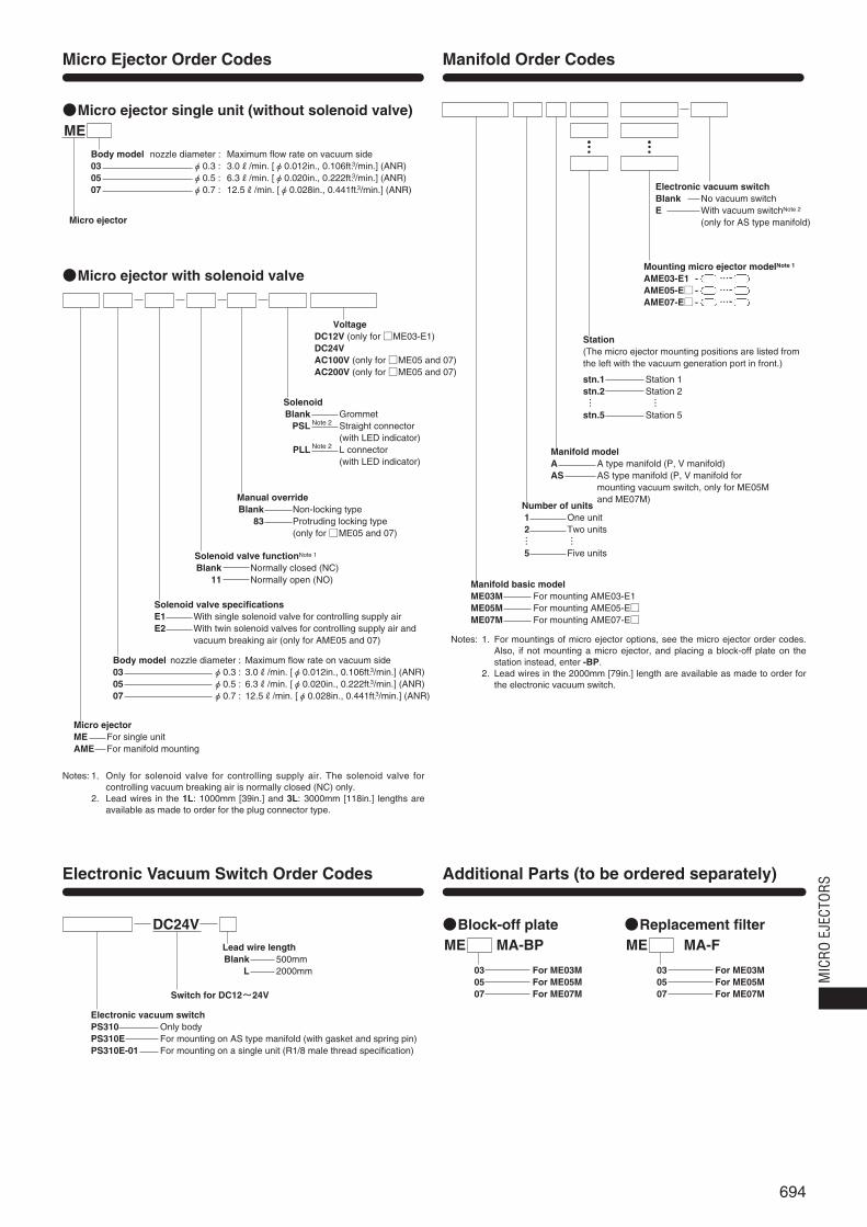
Micro Ejector Order Codes Manifold Order Codes
Electronic Vacuum Switch Order Codes Additional Parts (to be ordered separately)
Electronic vacuum switchBlank No vacuum switchE With vacuum switchNote 2
(only for AS type manifold)
Station(The micro ejector mounting positions are listed fromthe left with the vacuum generation port in front.)
stn.1 Station 1stn.2 Station 2… …stn.5 Station 5
Notes: 1. For mountings of micro ejector options, see the micro ejector order codes.Also, if not mounting a micro ejector, and placing a block-off plate on thestation instead, enter -BP.
2. Lead wires in the 2000mm [79in.] length are available as made to order forthe electronic vacuum switch.
Mounting micro ejector modelNote 1
AME03-E1 - …-AME05-E□- …-AME07-E□- …-
●Micro ejector single unit (without solenoid valve)
●Micro ejector with solenoid valve
ME
Micro ejector
Body model nozzle diameter : Maximum flow rate on vacuum side03 φ0.3 : 3.0R/min. [φ0.012in., 0.106ft.3/min.] (ANR)05 φ0.5 : 6.3R/min. [φ0.020in., 0.222ft.3/min.] (ANR)07 φ0.7 : 12.5R/min. [φ0.028in., 0.441ft.3/min.] (ANR)
Number of units1 One unit2 Two units… …5 Five units
Manifold basic modelME03M For mounting AME03-E1ME05M For mounting AME05-E□ME07M For mounting AME07-E□
VoltageDC12V (only for □ME03-E1)DC24VAC100V (only for □ME05 and 07)AC200V (only for □ME05 and 07)
Notes: 1. Only for solenoid valve for controlling supply air. The solenoid valve forcontrolling vacuum breaking air is normally closed (NC) only.
2. Lead wires in the 1L: 1000mm [39in.] and 3L: 3000mm [118in.] lengths areavailable as made to order for the plug connector type.
SolenoidBlank Grommet
PSL Straight connector (with LED indicator)
PLL L connector (with LED indicator)
Note 2
Note 2
Manual overrideBlank Non-locking type
83 Protruding locking type (only for □ME05 and 07)
Solenoid valve functionNote 1
Blank Normally closed (NC)11 Normally open (NO)
Solenoid valve specificationsE1 With single solenoid valve for controlling supply airE2 With twin solenoid valves for controlling supply air and
vacuum breaking air (only for AME05 and 07)
Body model nozzle diameter : Maximum flow rate on vacuum side03 φ0.3 : 3.0R/min. [φ0.012in., 0.106ft.3/min.] (ANR)05 φ0.5 : 6.3R/min. [φ0.020in., 0.222ft.3/min.] (ANR)07 φ0.7 : 12.5R/min. [φ0.028in., 0.441ft.3/min.] (ANR)
Micro ejectorME For single unitAME For manifold mounting
DC24VLead wire lengthBlank 500mm
L 2000mm
Switch for DC12~24V
Electronic vacuum switchPS310 Only bodyPS310E For mounting on AS type manifold (with gasket and spring pin)PS310E-01 For mounting on a single unit (R1/8 male thread specification)
●Block-off plateME MA-BP
03 For ME03M05 For ME05M07 For ME07M
●Replacement filterME MA-F
03 For ME03M05 For ME05M07 For ME07M
MIC
RO E
JECT
ORS
695
V
P
Man
ifold
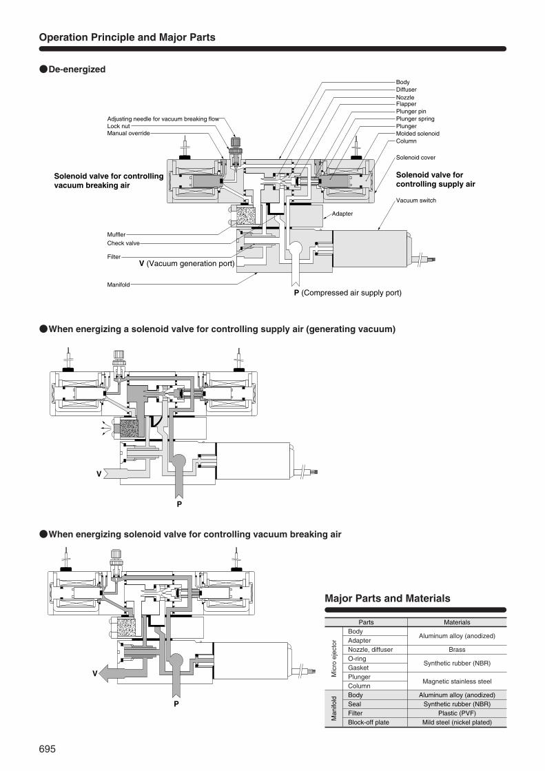
Parts Materials
Aluminum alloy (anodized)Synthetic rubber (NBR)
Plastic (PVF)Mild steel (nickel plated)
BodySealFilterBlock-off plate
Operation Principle and Major Parts
Mic
roej
ecto
r
Aluminum alloy (anodized)
Brass
Synthetic rubber (NBR)
Magnetic stainless steel
BodyAdapterNozzle, diffuserO-ringGasketPlungerColumn
Major Parts and Materials
●De-energized
●When energizing a solenoid valve for controlling supply air (generating vacuum)
●When energizing solenoid valve for controlling vacuum breaking air
Adjusting needle for vacuum breaking flowLock nutManual override
Solenoid valve for controlling supply air
Solenoid valve for controlling vacuum breaking air
MufflerCheck valve
Filter
Manifold
V (Vacuum generation port)
P (Compressed air supply port)
Adapter
Vacuum switch
Solenoid cover
ColumnMolded solenoidPlungerPlunger springPlunger pinFlapperNozzleDiffuserBody
V
P
696
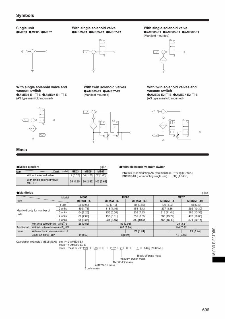
Symbols
Mass
Single unit●ME03 ●ME05 ●ME07
With single solenoid valve●ME03-E1 ●ME05-E1 ●ME07-E1
With single solenoid valve●AME03-E1 ●AME05-E1 ●AME07-E1(Manifold mounted)
With single solenoid valve andvacuum switch●AME05-E1-□-E ●AME07-E1-□-E(AS type manifold mounted)
With twin solenoid valves●AME05-E2 ●AME07-E2(Manifold mounted)
With twin solenoid valves andvacuum switch●AME05-E2-□-E ●AME07-E2-□-E(AS type manifold mounted)
Micro ejectors With electronic vacuum switchg [oz.]
PS310E (For mounting AS type manifold)……21g [0.74oz.]PS310E-01 (For mounting single unit)……38g [1.34oz.]
ME03 ME05 ME079 [0.32]Without solenoid valve 34 [1.20] 52 [1.83]
24 [0.85]With single solenoid valve ME□-E1
80 [2.82] 103 [3.63]
Item Basic model
Manifolds g [oz.]
ME07ME05ME03ME03M□A ME05M□A ME05M□AS ME07M□A ME07M□AS
1 unit2 units3 units4 units5 units
Manifold body for number ofunits
Additionalmass
With single solenoid valve -AME□-E1With twin solenoid valve -AME□-E2With electronic vacuum switch -EBlock-off plate -BP
26 [0.92] 62 [2.19] 81 [2.86] 120 [4.23] 148 [5.22]49 [1.73] 118 [4.16] 154 [5.43] 237 [8.36] 292 [10.30]64 [2.26] 156 [5.50] 202 [7.13] 313 [11.04] 385 [13.58]80 [2.82] 193 [6.81] 251 [8.85] 389 [13.72] 478 [16.86]95 [3.35]25 [0.88] 83 [2.93] 108 [3.81]
167 [5.89] 216 [7.62]── ─
6 [0.21] 13 [0.46]21 [0.74] ─ 21 [0.74]
2 [0.07]
231 [8.15] 299 [10.55] 465 [16.40] 571 [20.14]
ModelItem
Calculation example : ME05M5AS stn.1~2-AME05-E1stn.3~4-AME05-E2-Estn.5 mass of -BP 299 +(83 × 2)+(167 + 21)× 2 + 6 = 847g [29.88oz.]
5 units massAME05-E1 mass
AME05-E2 massVacuum switch mass
Block-off plate mass MIC
RO E
JECT
ORS
697
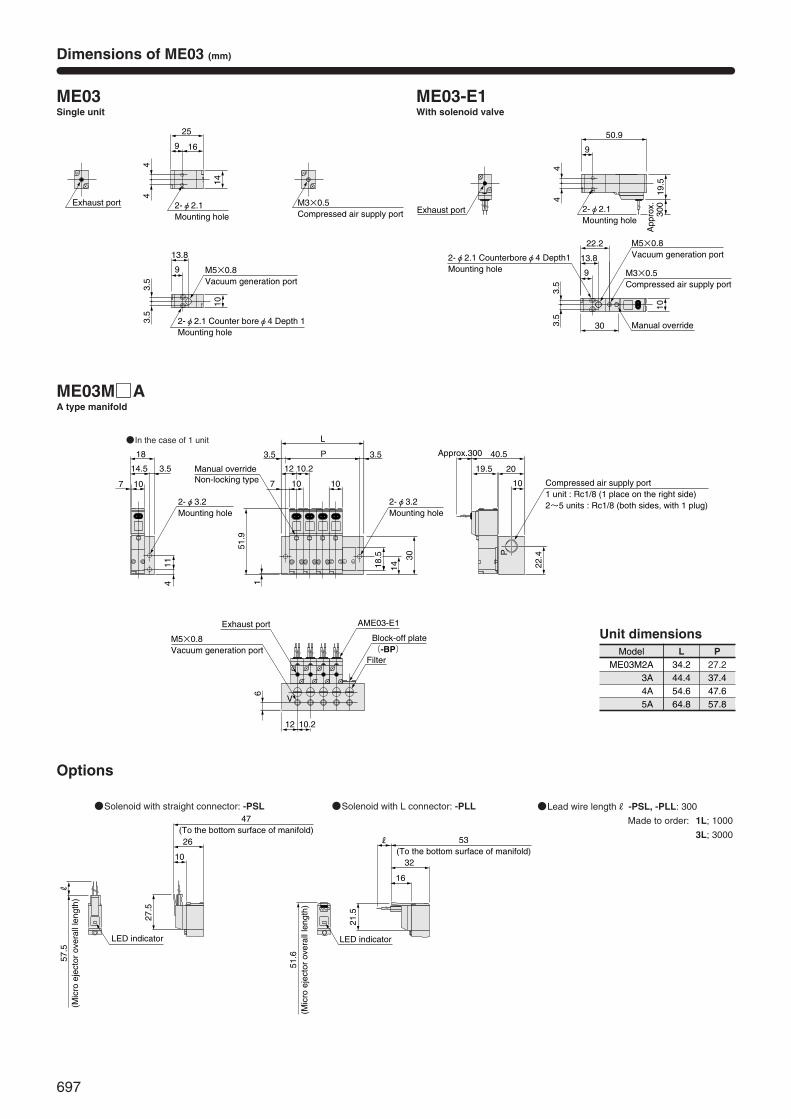
Dimensions of ME03 (mm)
ME03Single unit
ME03M□AA type manifold
ME03-E1With solenoid valve
●In the case of 1 unit
Options
●Solenoid with straight connector: -PSL ●Solenoid with L connector: -PLL ●Lead wire lengthR -PSL, -PLL: 300
Made to order: 1L; 1000
3L; 3000
ModelME03M2A 34.2
L27.2
3A 44.4 37.44A 54.6 47.65A 64.8 57.8
P
Unit dimensions
Exhaust port M3×0.5Compressed air supply port
M5×0.8Vacuum generation port
14
44
25
169
2-φ2.1Mounting hole
10
3.5
3.5
13.8
9
2-φ2.1 Counter boreφ4 Depth 1 Mounting hole
18
14.5 3.5
107
11
51.9
4
2-φ3.2Mounting hole
30
1418.5
2-φ3.2Mounting hole
1
Manual overrideNon-locking type 10
P
L
10
12 10.2
7
3.5 3.5
22.4P
10
2019.5
40.5Approx.300
Compressed air supply port1 unit : Rc1/8 (1 place on the right side)2~5 units : Rc1/8 (both sides, with 1 plug)
12 10.2
6
V
Exhaust port
M5×0.8Vacuum generation port
AME03-E1
Block-off plate(-BP)
Filter
Exhaust port
M3×0.5Compressed air supply port
M5×0.8Vacuum generation port
19.5
App
rox.
300
44
50.9
9
2-φ2.1Mounting hole
10
3.5
3.5
13.8
9
Manual override
22.2
30
2-φ2.1 Counterboreφ4 Depth1Mounting hole
R57
.5(M
icro
eje
ctor
ove
rall
leng
th)
LED indicator
27.5
47(To the bottom surface of manifold)26
10
51.6
(Mic
ro e
ject
or o
vera
ll le
ngth
)
LED indicator
21.5
53(To the bottom surface of manifold)
32
R
16
698
26
21
151.5
5
186
2-φ4.2Mounting hole
24
20
40
2-φ4.2Mounting hole
1616 17
55
L
P
17
1515 9.59.5
75
113.
5
Manual overrideNon-locking type : standard
Locking protruding type:-83
Adjusting needle for vacuum breaking flow
2424Approx.300
14.5MAX.12MIN.
13
P
327
4.3
Compressed air supply port
1617
V
6
49
62
76.5
MA
X.
74M
IIN.
AME05-E1 AME05-E2
Exhaust port
M5×0.8 Vacuum generation port
Block-off plate(-BP)
Filter
Adapter
1 unit : Rc1/8(1 place on the right side)2~5units : Rc1/8(both sides, with 1 plug)
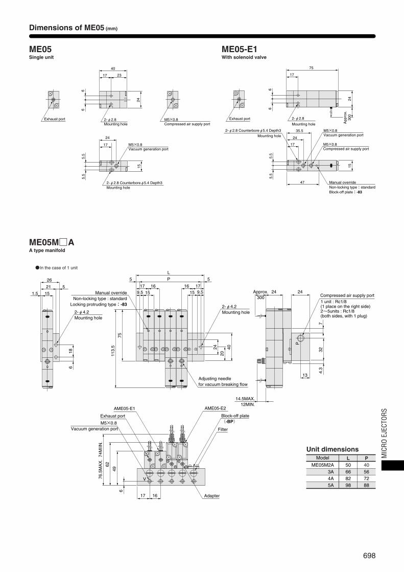
Dimensions of ME05 (mm)
ME05Single unit
ME05M□AA type manifold
ME05-E1With solenoid valve
●In the case of 1 unit
Model
ME05M2A 50L
403A 66 564A 82 725A 98 88
P
Unit dimensions
Exhaust port M5×0.8Compressed air supply port
24
66
23
40
17
2-φ2.8Mounting hole
M5×0.8Vacuum generation port
15
5.5
5.5
24
17
2-φ2.8 Counterboreφ5.4 Depth3Mounting hole
Exhaust port
24A
ppro
x.30
0
66
75
17
2-φ2.8
Mounting hole
M5×0.8Vacuum generation port
15
5.5
5.5
35.5
24
17
2-φ2.8 Counterboreφ5.4 Depth3Mounting hole
M5×0.8Compressed air supply port
47 Manual overrideNon-locking type:standardBlock-off plate:-83
MIC
RO E
JECT
ORS

699
1617
V
6
49
62
76.5
MA
X.
74M
IIN.
Filter
Adapter
26
21
151.5
5
186
2-φ4.2Mounting hole
24
20
52
2-φ4.2Mounting hole
1616 17
55
LED indicatorVacuum switch
L
P
17
1515 9.59.5
75
113.
5133.
5Manual override
Non-locking type : standardLocking protruding type : -83
Adjusting needle for vacuum breaking flow
24
20 324Approx.300
14.5MAX.12MIN.
13
P
32
954.
3
Compressed air supply port1 unit : Rc1/8(1 place on the right side)2~5 units : 2-Rc1/8(both sides, with 1 plug)
AME05-E1 AME05-E2
Exhaust port
M5×0.8 Vacuum generation port
Block-off plate(-BP)
App
rox.
500
ME05M□ASAS type manifold
●In the case of 1 unit
Options
●Solenoid with straight connector : -PSL ●Solenoid with L connector : -PLL ●Locking protruding type manual override : -83
Model
ME05M2AS 50L
403AS 66 564AS 82 725AS 98 88
P
Unit dimensions
Model Code
ME05-E1, AME05-E1 84 59 76 70 -PSL, -PLL:300
Made to order : 1L ; 1000, 3L ; 3000AME05-E2 131.5 72 115.5 83
A B C D R (Lead wire length)
R
37
A(M
icro
eje
ctor
ove
rall
leng
th)
LED indicator
34
B (To the bottom surface of manifold)
10
36.5
29
C
(Mic
ro e
ject
or o
vera
ll le
ngth
)
45
D
(To the bottom surface of manifold)
21
28.5
R
LED indicator
6.5
φ6
Dimensions of ME05 (mm)
700
25
181
15
5
22 120.
2
86.2
10
2-φ4.2Mounting hole
30 P
L
2020 1919
1818
15
1111
5 5
29
25
50
4.6
2-φ4.2Mounting hole
Manual overrideNon-locking type : standard
Locking protruding type : -83
Adjusting needle for vacuum breaking flow
3224
27Approx.300
14.5MAX.12MIN.
17
P
427.
34.
3
Compressed air supply port1 unit : Rc1/8(1 place on the right side)2~5 units : 2-Rc1/8(both sides, with 1 plug)
AME07-E2
Block-off plate(-BP)
Filter
AME07-E1
Exhaust port
Rc1/8 Vacuum generation port
1920
V
860
77
89M
IN.
91.5
MA
X.
Adapter
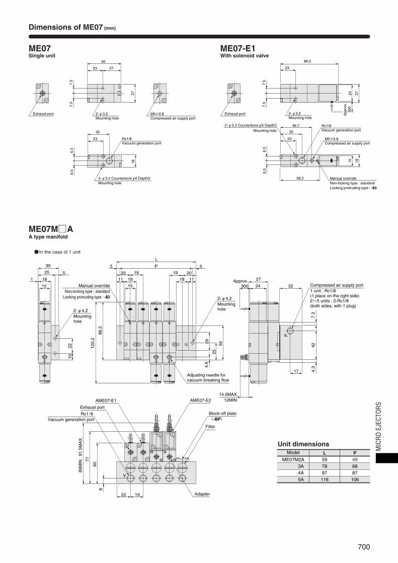
Dimensions of ME07 (mm)
ME07Single unit
ME07M□AA type manifold
ME07-E1With solenoid valve
●In the case of 1 unit
Model
ME07M2A 59L
493A 78 684A 97 875A 116 106
P
Unit dimensions
Exhaust port M5×0.8Compressed air supply port
27
7.5
7.5
27
50
23
2-φ3.2Mounting hole
Rc1/8Vacuum generation port
18
6.5
6.5
32
23
2-φ3.2 Counterboreφ6 Depth3Mounting hole
Exhaust port
2724A
ppro
x.30
07.5
7.5
86.2
23
2-φ3.2Mounting hole
Rc1/8Vacuum generation port
15
6.5
6.5
46.7
32
23
2-φ3.2 Counterboreφ6 Depth3Mounting hole
M5×0.8Compressed air supply port
18
58.2 Manual overrideNon-locking type : standardLocking protruding type : -83
MIC
RO E
JECT
ORS

701
27 32
20 11
17
24Approx.
300Compressed air supply port1 unit: Rc1/8(1 place on the right side)2~5 units: 2-Rc1/8(both sides, with 1 plug)
105
4.3
App
rox.
500
42
14.5MAX.12MIN.
P
30
25
18
151
5
2-φ4.2
Mounting hole
2210
L
P
20 19
2-φ4.2Mounting hole
4.6
18
19 20
1811 11
5 5
15
29
25
62
Adjusting needle for vacuum breaking flow
LED indicator
Vacuum switch
Manual override
Non-locking type: standardLocking protruding type : -83
139
120.
2
86.2
AME07-E1 AME07-E2Exhaust port
Rc1/8Vacuum generation port
Block-off plate(-BP)
Filter
608
77
89M
IN.
91.5
MA
X.
20 19 Adapter
V
ME07M□ASAS type manifold
●In the case of 1 unit
Model
ME07M2AS 59L
493AS 78 684AS 97 875AS 116 106
P
Unit dimensions
Options
●Solenoid with straight connector : -PSL ●Solenoid with L connector : -PLL ●Locking protruding type manual override : -83
Model Code
ME07-E1, AME07-E1 95.2 68.5 87.2 79.5 -PSL, -PLL : 300Made to order : 1L ; 1000, 3L ; 3000AME07-E2 138.2 85.5 122.2 96.5
A B C D R (Lead wire length)
6.5
φ6
29 28.5
C
(Mic
ro e
ject
or o
vera
ll le
ngth
)
D(To the bottom surface of manifold)
LED indicator
46.5
21
R
R
37 36.5
A(M
icro
eje
ctor
ove
rall
leng
th)
(To the bottom surface of manifold)
LED indicator
35.5
B
10
Dimensions of ME07 (mm)

702
kPaー101.3
Maximum vacuum level ー73.3
ー18.7
Vac
uum
Vac
uum
Time
0
s
t1 t2
S1 de-energizingS1 energizing
S1 de-energizingS1 energizing S2 energizing
kPaー101.3
Maximum vacuum level ー73.3
ー18.7
Time
0
s
t1 t3
0
5
10
15
20
25
30
35
0.1 0.2 0.3 0.4 0.5 0.6
Supply pressure MPa
R/min(ANR)
ー13.3
ー26.7
ー40.3
ー53.3
ー66.7
ー80.3
ー93.3
kPa
Vac
uum
Compressed air consumption
Vacuum flow rate
Vacuum
Vac
uum
flow
rat
eC
ompr
esse
d ai
r co
nsum
ptio
n
ー13.3
ー26.7
ー40.3
ー53.3
ー66.7
ー80.3
ー93.3
kPa
Vac
uum
0
2
4
6
8
10
12
14
0.1 0.2 0.3 0.4 0.5 0.6
Supply pressure MPa
R/min(ANR)
Compressed air consumption
Vacuum flow rate
Vacuum
Vac
uum
flow
rat
eC
ompr
esse
d ai
r co
nsum
ptio
n
0
ー13.3
ー26.7
ー40.3
ー53.3
ー66.7
ー80.3
ー93.3
kPa
1
2
3
4
5
6
7
0.1 0.2 0.3 0.4 0.5 0.6
Vac
uum
Supply pressure MPa
R/min(ANR)
Compressed air consumption
Vacuum flow rate
Vacuum
Vac
uum
flow
rat
eC
ompr
esse
d ai
r co
nsum
ptio
n
Dimensions of Electronic Vacuum Switch (mm)
Air Consumption, Vacuum and Vacuum Flow Rate
Time to Reach Vacuum and Vacuum Breaking Time
PS310E-01
Chamber capacity cm3 [in.3]
ME03
ME05
ME07
0.4 0.1 ― 0.7 0.2 ― 1.1 0.3 ― 3.2 0.6 ― 5.8 1.1 ― ― ― ― ― ― ―
0.2 0.1 0.1 0.3 0.1 0.1 0.5 0.1 0.1 1.5 0.3 0.1 2.6 0.5 0.2 7.0 0.8 0.4 12.0 1.8 0.8
0.1 0.1 0.1 0.2 0.1 0.1 0.3 0.1 0.1 0.6 0.2 0.1 1.0 0.3 0.2 1.8 0.4 0.4 4.7 1.0 0.8
5 [0.305]
t1 t2 t3 t1 t2 t3 t1 t2 t3 t1 t2 t3 t1 t2 t3 t1 t2 t3 t1 t2 t3
10 [0.610] 20 [1.22] 50 [3.05] 100 [6.10] 200 [12.2] 500 [30.5]
Model Time
Response time
Pressure adjusting screw
Hysteresis adjusting screw
LED indicator
15
20
61 Approx. 500
52.58.5R1/8
M5×0.8 (female) Depth5Pressure inlet port
●ME03
●Measurement method●ME□-E1
●ME□-E2
●ME05 ●ME07
Remark: Graphs are for each single ejector unit. If the unit with solenoid valve requires the same vacuum level, set the supply pressure 0.03~0.05MPa [4.4~7.3psi.] higher than the single ejector unit’s case.
Oscilloscope
Chamber
S2: Solenoid valve for controlling vacuum breaking air
S1: Solenoid valve for controlling supply air
Air pressure: 0.5MPa [73psi.]Adjusting needle for vacuumbreaking flow: Fully opent1: Time to reach ー73.3kPa
[ー21.65in.Hg] in the chamberafter energizing S1.
t2: In ME□-E1, time to reach ー18.7 kPa [ー5.52in.Hg] in thechamber after de-energizing S1.
t3: In ME□-E2, time to reach ー18.7kPa [ー5.52in.Hg] in thechamber after energizing S2 andwhen vacuum was at its maximumlevel.
Note: Some degree of variation may occur due to piping size and chamber shape. The figures can be viewed as a guide.
s
1MPa = 145psi. 1kPa = 0.145psi. -100kPa = -29.54in.Hg 1R/min = 0.0353ft.3/min.
MIC
RO E
JECT
ORS
Micro ejector body with twin solenoid valves
Gasket
Check valve
Adapter
Adapter cover
End cover
Manifold body
Filter
Filter cap
O-ring
Muffler
Spring pin
Gasket
Vacuum switch
Plug
O-ring
Lock pin
Gasket
Micro ejector body with single solenoid valve
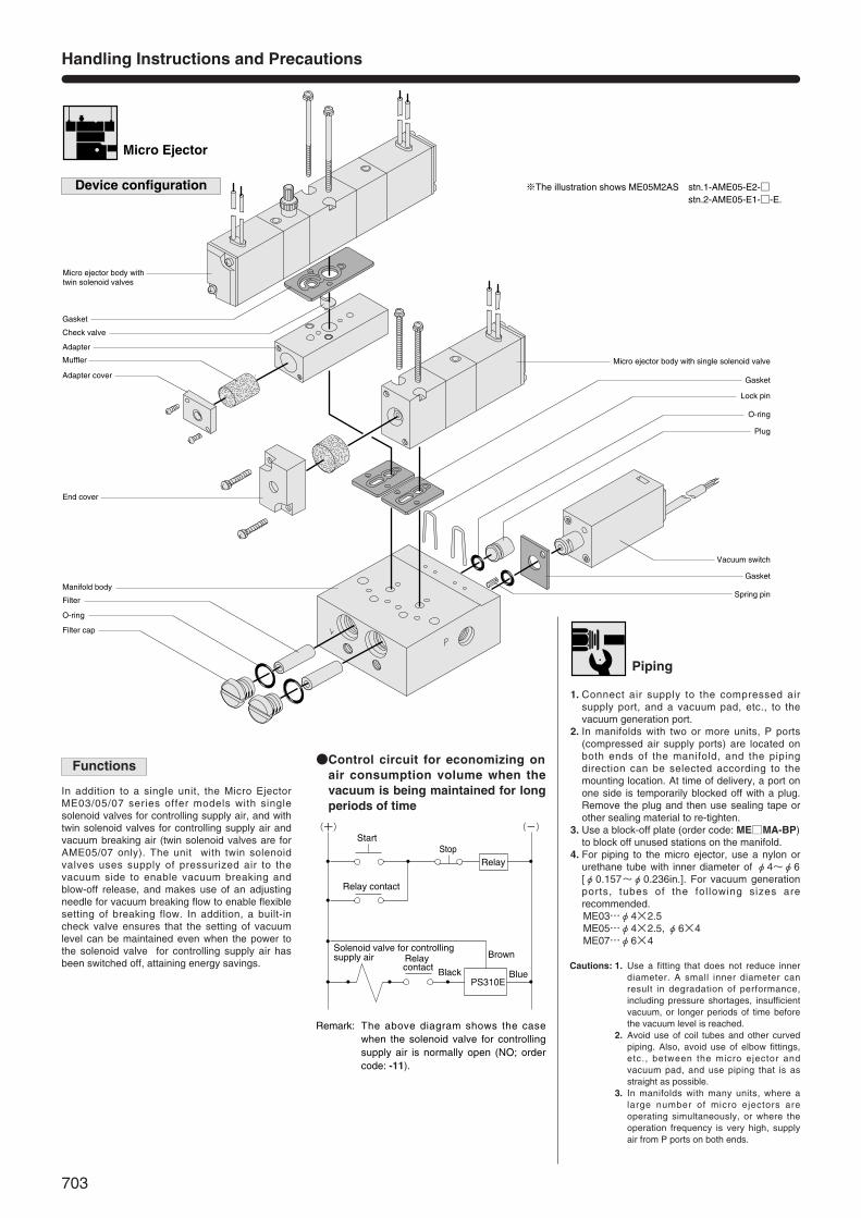
※The illustration shows ME05M2AS stn.1-AME05-E2-□ stn.2-AME05-E1-□-E.
Handling Instructions and Precautions
Micro Ejector
Device configuration
In addition to a single unit, the Micro EjectorME03/05/07 series offer models with singlesolenoid valves for controlling supply air, and withtwin solenoid valves for controlling supply air andvacuum breaking air (twin solenoid valves are forAME05/07 only). The unit with twin solenoidvalves uses supply of pressurized air to thevacuum side to enable vacuum breaking andblow-off release, and makes use of an adjustingneedle for vacuum breaking flow to enable flexiblesetting of breaking flow. In addition, a built-incheck valve ensures that the setting of vacuumlevel can be maintained even when the power tothe solenoid valve for controlling supply air hasbeen switched off, attaining energy savings. Cautions: 1. Use a fitting that does not reduce inner
diameter. A small inner diameter canresult in degradation of performance,including pressure shortages, insufficientvacuum, or longer periods of time beforethe vacuum level is reached.
2. Avoid use of coil tubes and other curvedpiping. Also, avoid use of elbow fittings,etc., between the micro ejector andvacuum pad, and use piping that is asstraight as possible.
3. In manifolds with many units, where alarge number of micro ejectors areoperating simultaneously, or where theoperation frequency is very high, supplyair from P ports on both ends.
Functions ●Control circuit for economizing onair consumption volume when thevacuum is being maintained for longperiods of time
1. Connect air supply to the compressed airsupply port, and a vacuum pad, etc., to thevacuum generation port.
2. In manifolds with two or more units, P ports(compressed air supply ports) are located onboth ends of the manifold, and the pipingdirection can be selected according to themounting location. At time of delivery, a port onone side is temporarily blocked off with a plug.Remove the plug and then use sealing tape orother sealing material to re-tighten.
3. Use a block-off plate (order code: ME□MA-BP)to block off unused stations on the manifold.
4. For piping to the micro ejector, use a nylon orurethane tube with inner diameter of φ4~φ6[φ0.157~φ0.236in.]. For vacuum generationports, tubes of the following sizes arerecommended.ME03…φ4×2.5ME05…φ4×2.5, φ6×4ME07…φ6×4
Start(+) (ー)
StopRelay
Relay contact
Relay contact
Solenoid valve for controlling supply air
PS310EBlack
Brown
Blue
Remark: The above diagram shows the casewhen the solenoid valve for controllingsupply air is normally open (NO; ordercode: -11).
Piping
703

※The figure shows ME05-E1.
Connector assembly
C
Contact
Lever
Plug connector
Protruded section
Pin
Connector housing
Indication of polarity (DC)
Solenoid
Internal circuit
Cautions: 1. Do not apply megger between the leadwires.
2. For DC12V, DC24V, while there is nodanger with a solenoid of a short circuitby the wrong polarity, the valve will notoperate.
3. Leakage current inside the circuit couldresult in failure of the solenoid valve notto return to home position or other erraticoperation.
3. Always use within the range of theallowable leakage current. If circuit condi-tions, etc., cause the leakage current toexceed the maximum allowable leakagecurrent, consult us.
Use fingers to insert the connector into the pin,push it in until the lever claw latches onto theprotruded section on the connector housing, andcomplete the connection.To remove the connector, squeeze the lever alongwith the connector, lift the lever claw up from theprotruded section of the connector housing, andpull it out.
To operate non-locking type, use a tool with a thintip (such as a small screwdriver) to press themanual override all the way down. The microejector works the same as an energized state aslong as the manual override is pushed down, andreturns to the reset position upon release.To lock the locking protruding type manual over-ride, use fingertips or a small screwdriver to pushdown on the manual override all the way and turnit 45 degrees or more. Either turning direction atthis time is acceptable. When locked, turing themanual override from the locking position releasesa spring on the manual override, returns it to itsoriginal position, and release the lock. If manualoverride is not turned, this type acts just like thenon-locking type. The micro ejector works thesame as an energized state as long as the manualoverride is pushed down, and returns to the resetposition upon release.
Plug connector
Attaching and removing plug connector
Manual override
Non-locking type and locking protruding type
●DC12V, DC24 (surge suppression)
Standard solenoid
Solenoid with LED indicator
Order code: -PSL, -PLL
Standard solenoid
Solenoid with LED indicator
Order code: -PSL, -PLL
●AC100V, AC200V (surge suppression)
Short circuit protection diode
SolenoidLead wire DC12V: Brown DC24V: Red
Lead wire: Black
+
ー Flywheel diode
Lead wire DC12V: Brown DC24V: Red
Lead wire: Black
+
ー
LED indicator(Light emitting diode)
LED indicator: Red
SolenoidVaristor
Lead wire AC100V: Yellow AC200V: White
Diode
LED indicator AC100V: Yellow AC200V: Green
LED indicator(Light emitting diode)
Lead wire AC100V: Yellow AC200V: White
Hook Exposed wire crimping section
Insulation crimp tab
Contact
Exposed wire 4mm
Lead wire
Insulation
Lead wire □ME03 Equivalent to AWG 28
□ME05 Equivalent to AWG 24□ME07
PUSH
Caution: Always release the lock on the lockingprotruding type manual override beforecommencing normal operation.
V
P
704
Crimping of connecting lead wire and contact
To crimp lead wires into contacts, strip off 4mm[0.16in.] of the insulation from the end of the leadwire, insert it into the contact, and crimp it. Be sureto avoid catching the insulation on the exposedwire crimping section.
Attaching and removing contact and connector
Insert the contact with a lead wire into a plugconnector □ hole until the contact hook latches on the connector and is secured to the plugconnector. Confirm that the lead wire cannot beeasily pulled out.To remove it, insert a tool with a fine tip (such as asmall screwdriver) into the rectangular hole on theside of the plug connector to push up on the hook,and then pull out the lead wire.
Cautions: 1. Do not pull hard on the lead wire. It couldresult in defective contacts, breakingwires, etc.
2. If the pin is bent, use a small screw-driver, etc., to gently straighten out thepin, and then complete the connection tothe plug connector.
3. For crimping of connecting the lead wireand contact, always use a dedicatedcrimping tool.Contact: Model 702062-2M
Manufactured by Sumiko Tech, Inc.
Crimping tool: Model F1-702062Manufactured by Sumiko Tech, Inc.
Adjustment of vacuum breaking flow rate
Rotate the adjusting needle for vacuum breakingflow (with twin solenoid valves only) in theclockwise direction to reduce the breaking flowrate, and in the counterclockwise direction toincrease the breaking flow rate.
Vacuum breaking
MIC
RO E
JECT
ORS
705
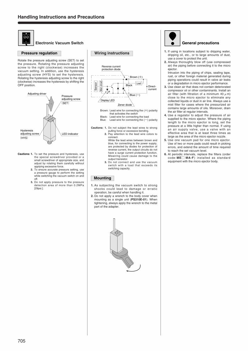
Reverse current protection diode
Brown (+)
Load
Blue (ー)
Direct-current
Display LED
Zener diode
Black
Sen
sor
Mai
n cir
cuit
1. As subjecting the vacuum switch to strongshocks could lead to damage or erraticoperation, be careful when handling it.
2. Do not apply a wrench to the body cover whenmounting as a single unit (PS310E-01). Whentightening, always apply the wrench to the metalpart of the adapter.
Electronic Vacuum Switch
Pressure regulation
Cautions: 1. To set the pressure and hysteresis, usethe special screwdriver provided or asmall screwdriver of appropriate size, andadjust by rotating them carefully withoutapplying excessive force.
2. To ensure accurate pressure setting, usea pressure gauge to perform the settingwhile switching the vacuum switch on andoff.
3. Do not apply pressure to the pressuredetection area of more than 0.2MPa[29psi.].
Rotate the pressure adjusting screw (SET) to setthe pressure. Rotating the pressure adjustingscrew to the right (clockwise) increases thevacuum setting. In addition, use the hysteresisadjusting screw (HYS) to set the hysteresis.Rotating the hysteresis adjusting screw to the right(clockwise) increases the hysteresis by shifting theOFF position.
1. If using in locations subject to dripping water,dripping oil, etc., or to large amounts of dust,use a cover to protect the unit.
2. Always thoroughly blow off (use compressedair) the piping before connecting it to the microejector. Intrusion into the piping of chips, sealing tape,rust, or other foreign material generated duringpiping operations could result in valve air leaksor a degradation in micro ejector performance.
3. Use clean air that does not contain deterioratedcompressor oil or other contaminants. Install anair filter (with filtration of a minimum 40μm)close to the micro ejector to eliminate anycollected liquids or dust in air line. Always use amist filter for cases where the pressurized aircontains large amounts of oils. Moreover, drainthe air filter at regular intervals.
4. Use a regulator to adjust the pressure of airsupplied to the micro ejector. Where the pipinglength to the micro ejector is long, set thepressure at a little higher than normal. If usingan air supply valve, use a valve with aneffective area that is at least three times aslarge as the area of the micro ejector nozzle.
5. Use one vacuum pad for one micro ejector.Use of two or more pads could result in pickingerrors, and extend the amount of time requiredto reach the set vacuum level.
6. At periodic intervals, replace the filters (ordercode: ME□ MA-F ) installed as standardequipment with the micro ejector body.
Wiring instructions
Mounting
General precautions
Adjusting driverPressure adjusting screw
(SET)
Hysteresis adjusting screw
(HYS)LED indicator
SETHYS
Brown: Lead wire for connecting the (+) polaritythat activates the switch
Black: Lead wire for connecting the loadBlue: Lead wire for connecting the (ー) polarity
Cautions: 1. Do not subject the lead wires to strongpulling force or excessive bending.
2. Pay attention to the lead wire colors toconnect.While the lead wires between brown andblue, for connecting to the power supply,are protected by diodes for protection ofreverse current, the output circuits do nothave a surge current protection function.Miswiring could cause damage to theoutput transistor.
3. Do not connect and use the vacuumswitch with a load that exceeds itsswitching capacity.
SETHYS
Handling Instructions and Precautions
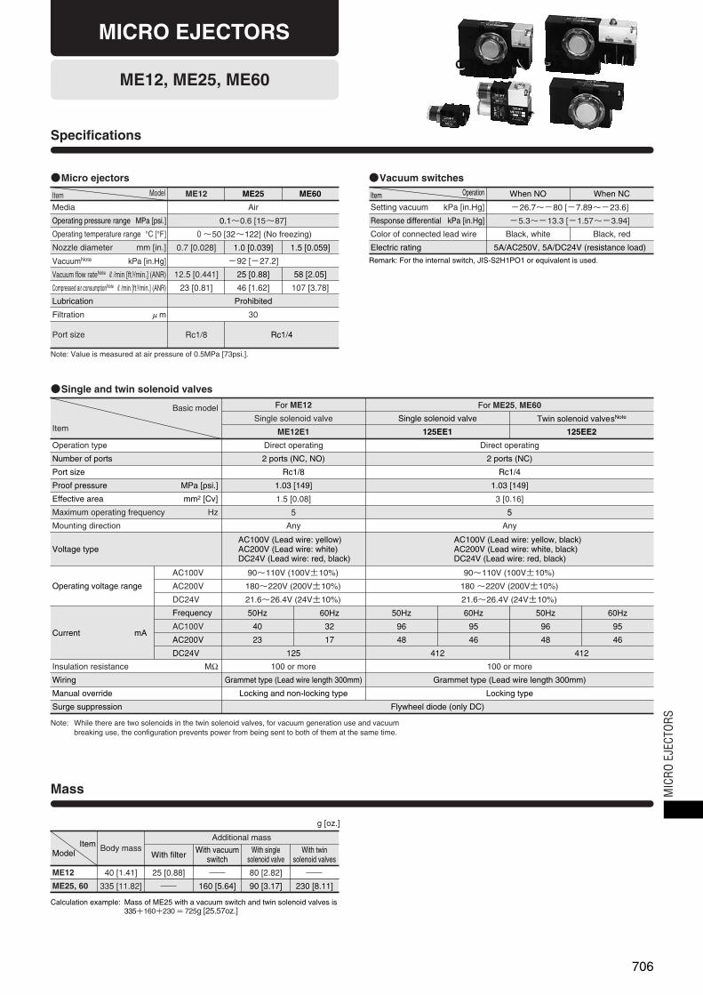
AirMedia
0.1~0.6 [15~87]Operating pressure range MPa [psi.]
0~50 [32~122] (No freezing)Operating temperature range °C [°F]
ー92 [ー27.2]VacuumNote kPa [in.Hg]
0.7 [0.028] 1.0 [0.039] 1.5 [0.059]Nozzle diameter mm [in.]
12.5 [0.441] 25 [0.88] 58 [2.05]Vacuum flow rateNote R/min [ft.3/min.] (ANR)
23 [0.81] 46 [1.62] 107 [3.78]Compressed air consumptionNote R/min [ft.3/min.] (ANR)
ProhibitedLubrication
30Filtration μm
Rc1/8 Rc1/4Port size
ME12 ME25 ME60Item Model
ME12, ME25, ME60
Specifications
Note: Value is measured at air pressure of 0.5MPa [73psi.].
●Micro ejectors
Setting vacuum kPa [in.Hg]
When NO
ー26.7~ー80 [ー7.89~ー23.6]
Response differential kPa [in.Hg] ー5.3~ー13.3 [ー1.57~ー3.94]
Color of connected lead wire Black, white Black, red
Electric rating 5A/AC250V, 5A/DC24V (resistance load)
When NCItem Operation
Remark: For the internal switch, JIS-S2H1PO1 or equivalent is used.
●Vacuum switches
Operation type
For ME12
Direct operating Direct operating
Number of ports 2 ports (NC, NO) 2 ports (NC)
Port size Rc1/8 Rc1/4
Proof pressure MPa [psi.] 1.03 [149] 1.03 [149]
Effective area mm2 [Cv] 1.5 [0.08] 3 [0.16]
Maximum operating frequency Hz 5 5
Mounting direction Any Any
Voltage typeAC100V (Lead wire: yellow)AC200V (Lead wire: white)DC24V (Lead wire: red, black)
AC100V (Lead wire: yellow, black)AC200V (Lead wire: white, black)DC24V (Lead wire: red, black)
Operating voltage range
AC100V
AC200V
DC24V
90~110V (100V±10%) 90~110V (100V±10%)
180~220V (200V±10%) 180 ~220V (200V±10%)
21.6~26.4V (24V±10%) 21.6~26.4V (24V±10%)
Current mA
Frequency
AC100V
AC200V
DC24V
50Hz 60Hz 50Hz 60Hz50Hz 60Hz
96 95 96 9540 32
48 46 48 4623 17
412 412125
Insulation resistance MΩ 100 or more100 or more
Wiring Grammet type (Lead wire length 300mm)Grammet type (Lead wire length 300mm)
Surge suppression Flywheel diode (only DC)
Manual override Locking typeLocking and non-locking type
For ME25, ME60
Single solenoid valve Single solenoid valve Twin solenoid valvesNote
ME12E1 125EE1 125EE2Item
Basic model
●Single and twin solenoid valves
Note: While there are two solenoids in the twin solenoid valves, for vacuum generation use and vacuumbreaking use, the configuration prevents power from being sent to both of them at the same time.
Mass
ME12 40 [1.41]
Body mass
25 [0.88] 80 [2.82]
Additional mass
With filterWith vacuum
switchWith single
solenoid valveWith twin
solenoid valves
ItemModel
Calculation example: Mass of ME25 with a vacuum switch and twin solenoid valves is335+160+230 = 725g [25.57oz.]
ME25, 60 335 [11.82] 160 [5.64] 90 [3.17] 230 [8.11]
g [oz.]
706
MICRO EJECTORS
MIC
RO E
JECT
ORS
707
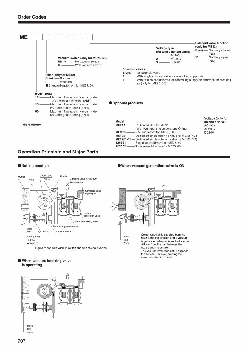
ME
Filter (only for ME12)Blank No filterF With filter●Standard equipment for ME25, 60.
Vacuum switch (only for ME25, 60)Blank No vacuum switchM With vacuum switch
Solenoid valvesBlank No solenoid valveS With single solenoid valve for controlling supply airT With twin solenoid valves for controlling supply air and vacuum breaking
air (only for ME25, 60)
Voltage type (for with solenoid valve)1 AC100V2 AC200V3 DC24V
Solenoid valve function (only for ME12)Blank Normally closed
(NC)11 Normally open
(NO)
Body model12 Maximum flow rate on vacuum side
12.5R/min [0.44ft.3/min.] (ANR)25 Maximum flow rate on vacuum side
25R/min [0.88ft.3/min.] (ANR)60 Maximum flow rate on vacuum side
58R/min [2.05ft.3/min.] (ANR)
Micro ejector
Order Codes
●Optional products
ModelMEF12 Dedicated filter for ME12
(With two mounting screws, one O-ring)MEM25 Vacuum switch for ME25, 60ME12E1 Dedicated single solenoid valve for ME12 (NC)ME12E1-11 Dedicated single solenoid valve for ME12 (NO)125EE1 Single solenoid valve for ME25, 60125EE2 Twin solenoid valves for ME25, 60
Voltage (only forsolenoid valve)AC100VAC200VDC24V
Operation Principle and Major Parts
●Not in operation ●When vacuum generation valve is ON
●When vacuum breaking valveis operating
MufflerFilter
Check valve
DiffuserNozzle
Adjusting valve for vacuum
breaking flow
Compressed airsupply port
Vacuum generation valve
Vacuum generation port
Vacuum switch
Vacuum breaking valve
Control nutMicro switch
Black (COM)
Red (NC)
White (NO)
Figure shows with vacuum switch and twin solenoid valves.
Compressed air is supplied from the nozzle into the diffuser, and a vacuum is generated when air is sucked into the diffuser from the gap between the nozzle and the diffuser.The vacuum level rises until it exceeds the set vacuum level, causing the vacuum switch to activate.
Black
Red
White
Black
Red
White
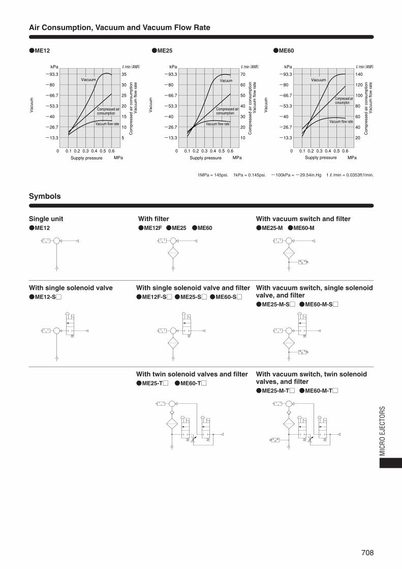
708
kPa
ー93.3
ー80.3
ー66.7
ー53.3
ー40.3
ー26.7
ー13.3
kPa
ー93.3
ー80.3
ー66.7
ー53.3
ー40.3
ー26.7
ー13.3
kPa
ー93.3
ー80.3
ー66.7
ー53.3
ー40.3
ー26.7
ー13.3
0 0.1 0.2 0.3 0.4 0.5 0.6
MPa
R/min(ANR)
35
30
25
20
15
10
5
0 0.1 0.2 0.3 0.4 0.5 0.6
MPa
R/min(ANR)
70
60
50
40
30
20
10
0 0.1 0.2 0.3 0.4 0.5 0.6
MPa
R/min(ANR)
140
120
100
80
60
40
20
Vac
uum
Supply pressure
Compressed air consumption
Vacuum flow rate
Vacuum
Vac
uum
Supply pressure
Compressed air consumption
Vacuum flow rate
Vacuum
Vac
uum
Supply pressure
Compressed air consumption
Vacuum flow rate
Vacuum
Vac
uum
flow
rat
eC
ompr
esse
d ai
r co
nsum
ptio
n
Vac
uum
flow
rat
eC
ompr
esse
d ai
r co
nsum
ptio
n
Vac
uum
flow
rat
eC
ompr
esse
d ai
r co
nsum
ptio
n
Air Consumption, Vacuum and Vacuum Flow Rate
Symbols
●ME12
Single unit
●ME25 ●ME60
●ME12
With filter●ME12F ●ME25 ●ME60
With vacuum switch and filter●ME25-M ●ME60-M
With single solenoid valve●ME12-S□
With single solenoid valve and filter●ME12F-S□ ●ME25-S□ ●ME60-S□
With vacuum switch, single solenoidvalve, and filter●ME25-M-S□ ●ME60-M-S□
With twin solenoid valves and filter●ME25-T□ ●ME60-T□
With vacuum switch, twin solenoidvalves, and filter●ME25-M-T□ ●ME60-M-T□
1MPa = 145psi. 1kPa = 0.145psi. -100kPa = -29.54in.Hg 1R/min = 0.0353ft.3/min.
MIC
RO E
JECT
ORS

709
●ME12 ●ME12-S□
Dimensions of ME12 (mm)
Compressed air supply port
Vacuum generation port
2-φ3.2Mounting hole 65
4010 7.5
2211
338
Approx.
300mm
Rc1/8Manual override
Rc1/8
25
1122
3 33747.7
10
2-φ3.2Mounting hole 50
4010 7.5
2211
Rc1/8
Rc1/8
Compressed air supply port
Vacuum generation port
8
10
1122
3
918
●ME12F ●ME12F-S□
2-φ3.2
654010 7.5
33
2211
8
Rc1/8
Rc1/8
2511
222244
3
373
47.7
10
Compressed air supply port
Vacuum generation port
Mounting hole
Approx.
300mm
Manual override
2-φ3.2
504010 7.5
2211
Rc1/8
Rc1/8
10
8
114422
22
3
918
Mounting hole
Compressed airsupply port
Vacuum generation port
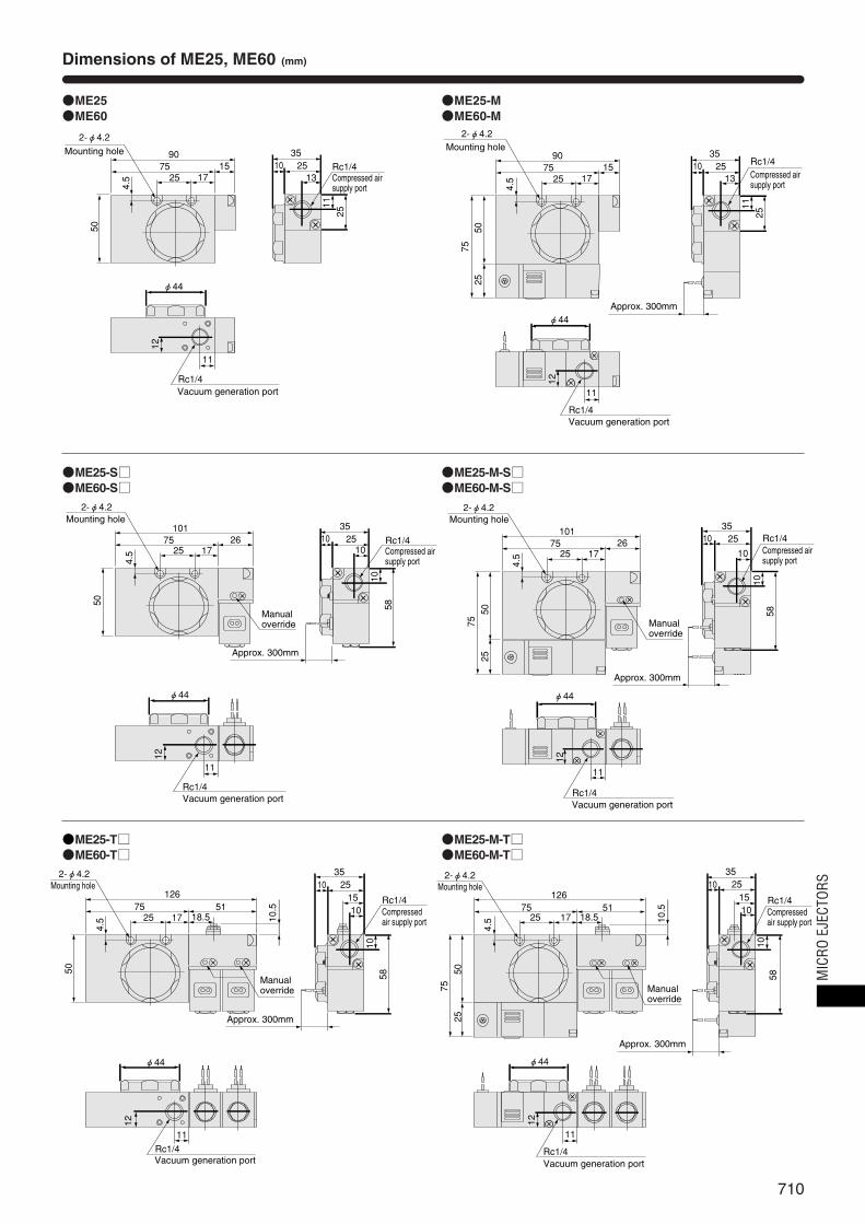
710
●ME25●ME60
●ME25-M●ME60-M
Dimensions of ME25, ME60 (mm)
9075
2-φ4.2
25 1715
3510 25
13
Rc1/4
φ44
11
Rc1/4
5025
75
12
4.5
1125
Compressed airsupply port
Vacuum generation port
Mounting hole
Approx. 300mm
9075
2-φ4.2
25 1715
3510 25
13Rc1/4
φ44
11
Rc1/4
50
12
4.5
1125
Compressed airsupply port
Vacuum generation port
Mounting hole
●ME25-S□●ME60-S□
●ME25-M-S□●ME60-M-S□
10175
2-φ4.2
25 17 1026
3510 25 Rc1/4
φ44
11
Rc1/4
5025
75
12
4.5
1058
Compressed airsupply port
Vacuum generation port
Mounting hole
Approx. 300mm
Manual override
10175
2-φ4.2
25 1726
3510 25
10Rc1/4
φ44
11
Rc1/4
50
12
4.5
1058
Compressed airsupply port
Vacuum generation port
Mounting hole
Approx. 300mm
Manual override
●ME25-T□●ME60-T□
●ME25-M-T□●ME60-M-T□
12675
2-φ4.2
25 17 18.5
151051
3510 25
Rc1/4
φ44
11Rc1/4
50
10.5
12
4.5
1058
Compressedair supply port
Vacuum generation port
Mounting hole
Approx. 300mm
Manual override
12675
2-φ4.2
25 17 18.5
151051
3510 25
Rc1/4
φ44
11
Rc1/4
7550
25
10.5
4.5
1058
12
Vacuum generation port
Mounting hole
Approx. 300mm
Manual override
Compressedair supply port
MIC
RO E
JECT
ORS
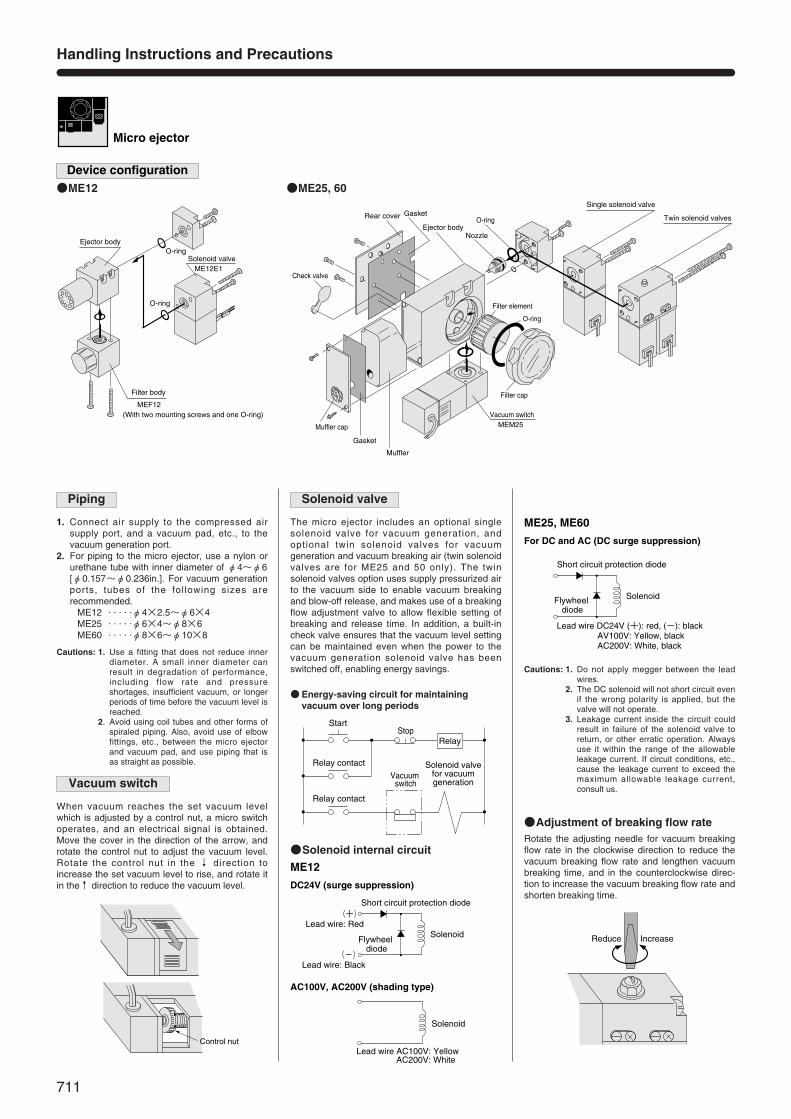
711
Reduce Increase
O-ring
O-ring
Nozzle
Gasket
Gasket
Muffler
Rear cover
Check valve
Ejector body
Muffler cap
Filter cap
Filter element
Vacuum switchMEM25
Single solenoid valve
Twin solenoid valves
Solenoid valveO-ring
O-ring
ME12E1
MEF12(With two mounting screws and one O-ring)
Ejector body
Filter body
Handling Instructions and Precautions
Micro ejector
Device configuration
1. Connect air supply to the compressed airsupply port, and a vacuum pad, etc., to thevacuum generation port.
2. For piping to the micro ejector, use a nylon orurethane tube with inner diameter of φ4~φ6[φ0.157~φ0.236in.]. For vacuum generationports, tubes of the following sizes arerecommended.
ME12 . . . . .φ4×2.5~φ6×4ME25 . . . . .φ6×4~φ8×6ME60 . . . . .φ8×6~φ10×8
Cautions: 1. Do not apply megger between the leadwires.
2. The DC solenoid will not short circuit evenif the wrong polarity is applied, but thevalve will not operate.
3. Leakage current inside the circuit couldresult in failure of the solenoid valve toreturn, or other erratic operation. Alwaysuse it within the range of the allowableleakage current. If circuit conditions, etc.,cause the leakage current to exceed themaximum allowable leakage current,consult us.
Piping
The micro ejector includes an optional singlesolenoid valve for vacuum generation, andoptional twin solenoid valves for vacuumgeneration and vacuum breaking air (twin solenoidvalves are for ME25 and 50 only). The twinsolenoid valves option uses supply pressurized airto the vacuum side to enable vacuum breakingand blow-off release, and makes use of a breakingflow adjustment valve to allow flexible setting ofbreaking and release time. In addition, a built-incheck valve ensures that the vacuum level settingcan be maintained even when the power to thevacuum generation solenoid valve has beenswitched off, enabling energy savings.
Solenoid valve
●Energy-saving circuit for maintainingvacuum over long periods
●Solenoid internal circuit
Start Stop
Vacuum switch
Solenoid valvefor vacuumgeneration
Relay
Relay contact
Relay contact
●ME12 ●ME25, 60
Cautions: 1. Use a fitting that does not reduce innerdiameter. A small inner diameter canresult in degradation of performance,including flow rate and pressureshortages, insufficient vacuum, or longerperiods of time before the vacuum level isreached.
2. Avoid using coil tubes and other forms ofspiraled piping. Also, avoid use of elbowfittings, etc., between the micro ejectorand vacuum pad, and use piping that isas straight as possible.
When vacuum reaches the set vacuum levelwhich is adjusted by a control nut, a micro switchoperates, and an electrical signal is obtained.Move the cover in the direction of the arrow, androtate the control nut to adjust the vacuum level.Rotate the control nut in the ↓ direction toincrease the set vacuum level to rise, and rotate itin the↑ direction to reduce the vacuum level.
Vacuum switch
Control nut
ME12
DC24V (surge suppression)
AC100V, AC200V (shading type)
Short circuit protection diode
SolenoidFlywheel
diode
Lead wire: Red(+)
Lead wire: Black(ー)
Solenoid
Lead wire AC100V: Yellow AC200V: White
ME25, ME60
For DC and AC (DC surge suppression)
Short circuit protection diode
SolenoidFlywheel diode
Lead wire DC24V (+): red, (ー): blackAV100V: Yellow, blackAC200V: White, black
●Adjustment of breaking flow rateRotate the adjusting needle for vacuum breakingflow rate in the clockwise direction to reduce thevacuum breaking flow rate and lengthen vacuumbreaking time, and in the counterclockwise direc-tion to increase the vacuum breaking flow rate andshorten breaking time.

712
10 [0.610] 50 [3.05] 200 [12.2] 1000 [61.0] 3000 [183] 5000 [305]
t1 t1
1.5
1.0
Time to Reach Vacuum and Vacuum Breaking Time
●Measurement circuits and conditions ●Measurement method
Chamber capacity cm3 [in.3]
ME12
Model Time
ME25
0.5
t2
─
0.1
0.1
t2 t2 t2 t2 t2t1
2.0
1.3
1.0
─
0.1
0.1
t1
4.0
2.0
1.5
─
0.2
0.2
t1
7.5
3.8
3.0
─
0.4
0.4
t1
26.0
13.0
10.0
─
1.5
1.5
t1
50.0
23.0
15.0
─
3.0
3.0
s
ME60
●Response time
Note: Some degree of variation may occur due to piping size and chamber shape. The figures can be viewed as a guide.
Air pressure: 0.5MPa [73psi.]t1: Time to reach ー73.3kPa
[ー21.65in.Hg] in the chamberafter energizing S1.
t2: Time to reach ー18.7kPa [ー5.52in.Hg] in the chamberafter energizing S2.
●Manual operation
ME12E1To lock the manual override, use a smallscrewdriver to push down the manual override allthe way and turn it 45 degrees or more. Eitherturning direction at this time is acceptable.When locked, turning the manual override fromthe locking position releases a spring on themanual override, returns it to its original position,and release the lock.
125EE1, 125EE2To lock, use a screwdriver to rotate the manualoverride 45 degrees and tilt the screw groove 45degrees. Either turning direction at this time isacceptable.To release the lock, rotate the manual override by45 degrees, and return the screw groove tohorizontal.
Caution: Always release the lock on the manual overridebefore commencing normal operation.
Oscilloscope
Chamber
Micro ejector
S1 (Solenoid valve for controlling supply air)
S2 (Solenoid valve for controlling vacuum breaking air)
kPaー101.3
ー73.3
ー18.7Vac
uum
Time
0
s
t1 t2
S1 de-energizingS1 energizing
Maximum vacuum level
OpenClosed
MIC
RO E
JECT
ORS

713