(micro atx motherboard) - · pdf filevoltage regulator on the motherboard to the required...
TRANSCRIPT
Hardware DocumentVersion 1.0
Como(Micro ATX Motherboard)
Prepared by Won Yul, LEEBoard Development Team, TriGem R&D
Updated on May, 6,1998
TriGem Computer, Inc.
Hardware Document for Como RPR404-1B1 Version 1.0
Board Development Team - 2 - Updated : May 6. 1998
TriGem Contact Information
Marketing InformationAddress : 45-2 Yoidodong, Youngdeungpoku, Seoul, KoreaTelephone : 82-2-3774-4251 (Ext. International Business Team)Fax : 82-2-786-9478Email : [email protected] (Jin-Hyun, Park)
Technical SupportAddress : 1055 Shingil-Dong, Ansan-City, Kyunggi-Do, Korea
( PO Box : Banwel Industrial Complex Post Office 18 )Telephone : 82-345-491-9528Fax : 82-345-493-6721Email : [email protected](Hyen-Ki, Baek)
wylee @trigem.co.kr(Won-Yul, Lee)
Manufacturing InformationAddress : 1055 Shingil-Dong, Ansan-City, Kyunggi-Do, Korea
(PO Box : Banwal Industrial Complex Poet Office 18)Telephone : 82-345-492-9528 (Ext. Manufacturing Team)Fax : 82-345-856-4392
: 82-345-492-0485
Revision History
Released data Revision DescriptionMarch 28, 1998 0.9 First released version
May 6, 1998 1.0 Pilot released version
User’s NoticeNo part of this product, including the product and software may be reproduced, transmitted, transcribed, storedin a retrieval system, or translated into any language in any form by any means without the express writtenpermission of TriGem Computer Inc. except document kept by the purchaser for backup purposes.
© Copyright 1998 TriGem Computer Inc. All rights reserved
Hardware Document for Como RPR404-1B1 Version 1.0
Board Development Team - 3 - Updated : May 6. 1998
Table of Contents
I. Introduction
1. Generation Description ------------------------------------------------------------ 4
2. Function Block Diagram -------------------------------------------------------- 5
II. System Overview
1. Major Units ---------------------------------------------------------------------- 6
2. Upgradeability --------------------------------------------------------------------- 6
2-1. Processor ---------------------------------------------------------------------- 6
2-2. Memory ------------------------------------------------------------------------ 7
2-3. Expansion Slot ---------------------------------------------------------------- 7
2-4. I/O Interface --------------------------------------------------------------- 8
2-5. Manufacturing Options ------------------------------------------------------- 8
III. Jumper & Connector Description
1. Motherboard Jumper Setting ------------------------------------------------------ 9
1-1. Selection for Pentium II processor CPU Clock ----------------------- 9
1-2. Other function control ------------------------------------------------------- 9
2. Motherboard Header Connector ------------------------------------------------ 10
3. Motherboard Internal I/O Connector ------------------------------------------- 13
Hardware Document for Como RPR404-1B1 Version 1.0
Board Development Team - 4 - Updated : May 6. 1998
I. Introduction
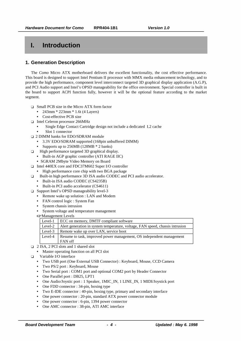
1. Generation Description
The Como Micro ATX motherboard delivers the excellent functionality, the cost effective performance.This board is designed to support Intel Pentium II processor with MMX media enhancement technology, and toprovide the high performance, component level interconnect targeted 3D graphical display application (A.G.P),and PCI Audio support and Intel’s OPSD manageability for the office environment. Special controller is built inthe board to support ACPI function fully, however it will be the optional feature according to the marketsegment.
❑ Small PCB size in the Micro ATX form factor• 243mm * 223mm * 1.6t (4 Layers)• Cost-effective PCB size
❑ Intel Celeron processor 266MHz• Single Edge Contact Cartridge design not include a dedicated L2 cache• Slot 1 connector
❑ 2 DIMM banks for EDO/SDRAM module• 3.3V EDO/SDRAM supported (168pin unbuffered DIMM)• Supports up to 256MB (128MB * 2 banks)
❑ High performance targeted 3D graphical display.• Built-in AGP graphic controller (ATI RAGE IIC)• SGRAM 2Mbyte Video Memory on Board
❑ Intel 440EX core and FDC37M602 Super I/O controller• High performance core chip with two BGA package
❑ Built-in high performance 3D ISA audio CODEC and PCI audio accelerator.• Built-in ISA audio CODEC (CS4235B)• Built-in PCI audio accelerator (CS4611)
❑ Support Intel’s OPSD manageability level-3• Remote wake up solution : LAN and Modem• FAN control logic : System Fan• System chassis intrusion• System voltage and temperature management☞ Management Levels
Level-1 ECC on memory, DMTF compliant softwareLevel-2 Alert generation in system temperature, voltage, FAN speed, chassis intrusionLevel-3 Remote wake up over LAN, service bootLevel-4 Resume to task, improved power management, OS independent management
FAN off❑ 2 ISA, 2 PCI slots and 1 shared slot
• Master operating function on all PCI slot❑ Variable I/O interface
• Two USB port (One External USB Connector) : Keyboard, Mouse, CCD Camera• Two PS/2 port : Keyboard, Mouse• Two Serial port : COM1 port and optional COM2 port by Header Connector• One Parallel port : DB25, LPT1• One Audio/Joystic port : 1 Speaker, 1MIC_IN, 1 LINE_IN, 1 MIDI/Joystick port• One FDD connector : 34-pin, boxing type• Two E-IDE connector : 40-pin, boxing type, primary and secondary interface• One power connector : 20-pin, standard ATX power connector module• One power connector : 6-pin, 1394 power connector• One AMC connector : 38-pin, ATI AMC interface

Hardware Document for Como RPR404-1B1 Version 1.0
Board Development Team - 5 - Updated : May 6. 1998
2. Function Block Diagram
cCrystal
I2C-SUS
CS4611
CS4235
Crystal
Video Conn
Intel
Intel
HD
MD
MA
DD
DA
HA
SMBus
Wake up
Wake up
SA
✲✲✲✲
Celeron Processor
DIMM Module
PCI slotHarddisk
IntrusioModem card
FANUSB
COM1
LPT
Keyboard
ISA slotMouse
Flash ROM
FDD
ATI Rage IIc
GAD
ATIPAC
PIIX4
SMC37M602
GMD
SGRAM
8MbiSGRAM
8Mbi
I/O
XD
AD
SD
LAN card
LM78
SPK
MIC
Line In
Joystic
Hardware Document for Como RPR404-1B1 Version 1.0
Board Development Team - 6 - Updated : May 6. 1998
II. System Overview
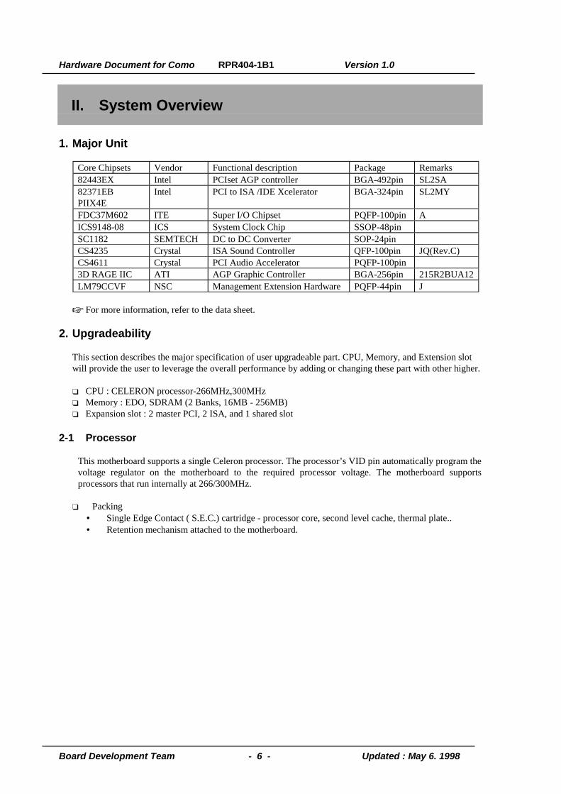
1. Major Unit
Core Chipsets Vendor Functional description Package Remarks82443EX Intel PCIset AGP controller BGA-492pin SL2SA82371EBPIIX4E
Intel PCI to ISA /IDE Xcelerator BGA-324pin SL2MY
FDC37M602 ITE Super I/O Chipset PQFP-100pin AICS9148-08 ICS System Clock Chip SSOP-48pinSC1182 SEMTECH DC to DC Converter SOP-24pinCS4235 Crystal ISA Sound Controller QFP-100pin JQ(Rev.C)CS4611 Crystal PCI Audio Accelerator PQFP-100pin3D RAGE IIC ATI AGP Graphic Controller BGA-256pin 215R2BUA12LM79CCVF NSC Management Extension Hardware PQFP-44pin J
☞ For more information, refer to the data sheet.
2. Upgradeability
This section describes the major specification of user upgradeable part. CPU, Memory, and Extension slot will provide the user to leverage the overall performance by adding or changing these part with other higher.
❑ CPU : CELERON processor-266MHz,300MHz❑ Memory : EDO, SDRAM (2 Banks, 16MB - 256MB)❑ Expansion slot : 2 master PCI, 2 ISA, and 1 shared slot
2-1 Processor
This motherboard supports a single Celeron processor. The processor’s VID pin automatically program thevoltage regulator on the motherboard to the required processor voltage. The motherboard supportsprocessors that run internally at 266/300MHz.
❑ Packing• Single Edge Contact ( S.E.C.) cartridge - processor core, second level cache, thermal plate..• Retention mechanism attached to the motherboard.
Hardware Document for Como RPR404-1B1 Version 1.0
Board Development Team - 7 - Updated : May 6. 1998
2-2. Memory
The memory controller, Intel 440EX support EDO module, and SDRAM module, up to two banks, howeverEDO and SDRAM module will be available with 168-pin unbuffered DIMM module and 3.3V version. TheBIOS automatically detects memory type, size, and speed.
The motherboard supports the following memory features.• 168-pin DIMMs with gold-plated contacts• 66MHz SDRAM only• Non-ECC(64-bit) memory• 3.3 V Memory only• Single- or double-sided DIMMs in the following sizes
DIMM Size Non-ECC Configuration8 MB 1 Mbit * 6416 MB 2 Mbit * 6432 MB 4 Mbit * 6464 MB 8 Mbit * 64128 MB 16 Mbit * 64
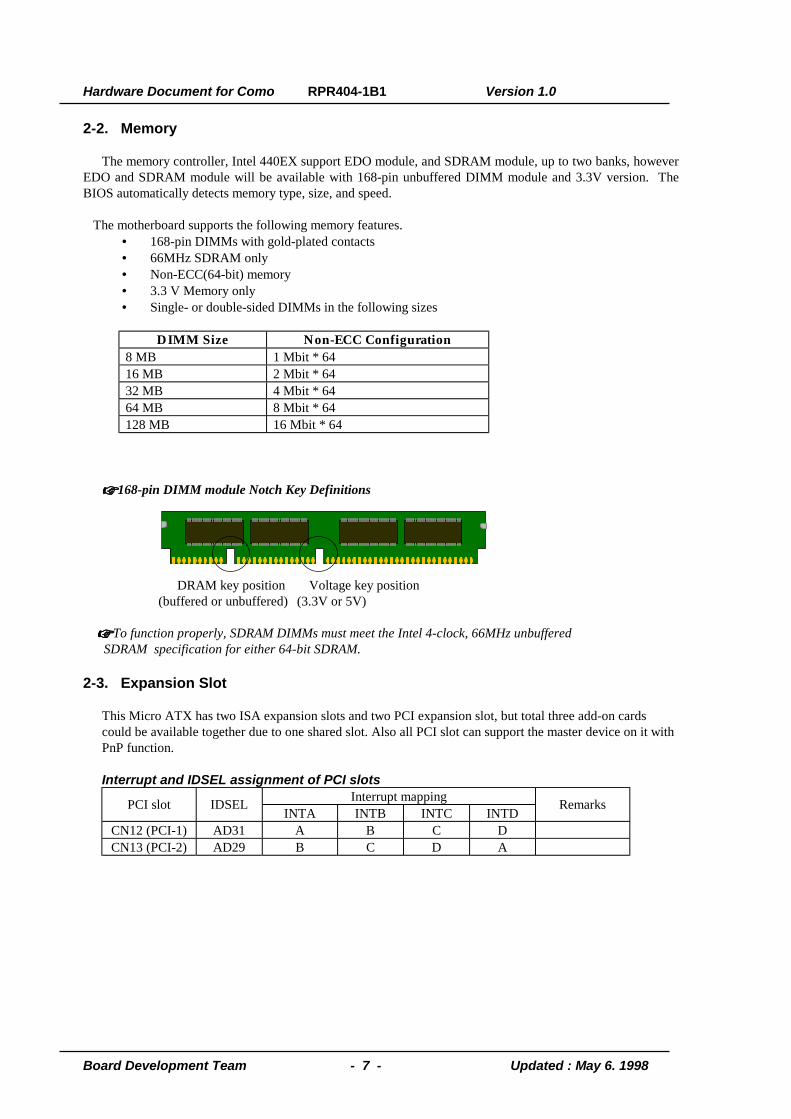
☞☞☞☞ 168-pin DIMM module Notch Key Definitions
DRAM key position Voltage key position(buffered or unbuffered) (3.3V or 5V)
☞☞☞☞ To function properly, SDRAM DIMMs must meet the Intel 4-clock, 66MHz unbuffered SDRAM specification for either 64-bit SDRAM.
2-3. Expansion Slot
This Micro ATX has two ISA expansion slots and two PCI expansion slot, but total three add-on cards could be available together due to one shared slot. Also all PCI slot can support the master device on it with PnP function.
Interrupt and IDSEL assignment of PCI slotsInterrupt mappingPCI slot IDSEL
INTA INTB INTC INTDRemarks
CN12 (PCI-1) AD31 A B C DCN13 (PCI-2) AD29 B C D A
Hardware Document for Como RPR404-1B1 Version 1.0
Board Development Team - 8 - Updated : May 6. 1998
2-4. I/O Interface
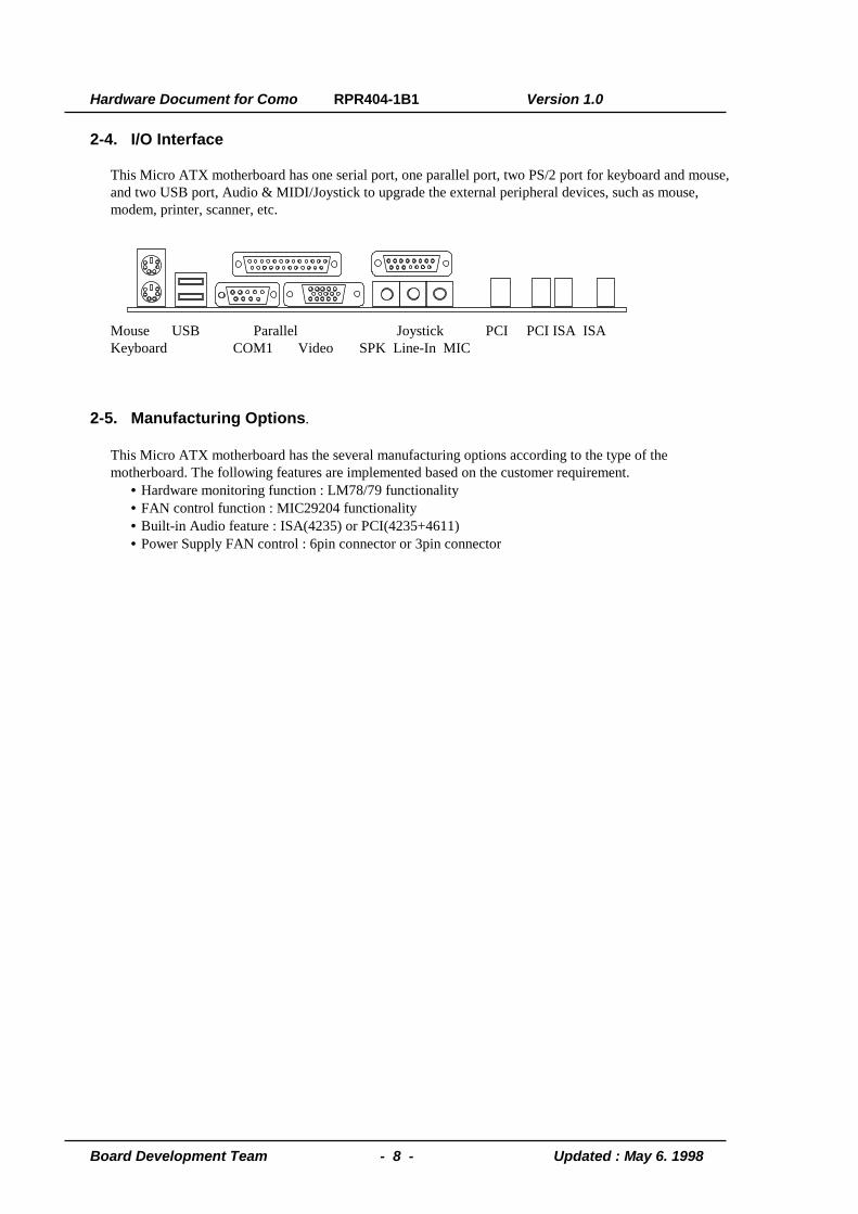
This Micro ATX motherboard has one serial port, one parallel port, two PS/2 port for keyboard and mouse, and two USB port, Audio & MIDI/Joystick to upgrade the external peripheral devices, such as mouse, modem, printer, scanner, etc.
Mouse USB Parallel Joystick PCI PCI ISA ISAKeyboard COM1 Video SPK Line-In MIC
2-5. Manufacturing Options.
This Micro ATX motherboard has the several manufacturing options according to the type of the motherboard. The following features are implemented based on the customer requirement.
• Hardware monitoring function : LM78/79 functionality• FAN control function : MIC29204 functionality• Built-in Audio feature : ISA(4235) or PCI(4235+4611)• Power Supply FAN control : 6pin connector or 3pin connector
Hardware Document for Como RPR404-1B1 Version 1.0
Board Development Team - 9 - Updated : May 6. 1998
III. Jumper & Connector Description
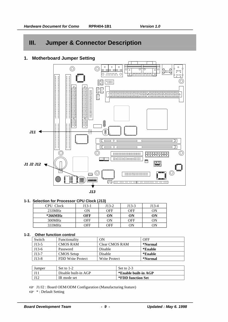
1. Motherboard Jumper Setting
J11
J1 J2 J12
J13
1-1. Selection for Processor CPU Clock (J13)CPU Clock J13-1 J13-2 J13-3 J13-4
233MHz ON OFF OFF ON*266MHz OFF ON ON ON300MHz OFF ON OFF ON333MHz OFF OFF ON ON
1-2. Other function controlSwitch Functionality ON OFFJ13-5 CMOS RAM Clear CMOS RAM *NormalJ13-6 Password Disable *EnableJ13-7 CMOS Setup Disable *EnableJ13-8 FDD Write Protect Write Protect *Normal
Jumper Set to 1-2 Set to 2-3J11 Disable built-in AGP *Enable built-in AGPJ12 IR mode set *FDD function Set
☞ J1/J2 : Board OEM/ODM Configuration (Manufacturing feature)☞ * : Default Setting

Hardware Document for Como RPR404-1B1 Version 1.0
Board Development Team - 10 - Updated : May 6. 1998
2. Motherboard Header Connector
CN70 CN46
CN44CN43CN45
CN23
SPK1
CN56 CN50 CN53 CN54 CN51 CN49 CN48 CN52 CN8(CN55)
2-1. CPU FAN Connector(CN53)Pin Number Signal Name
1 Ground2 FANCNTL3 FANSEN1
2-2. System FAN Connector(CN54)Pin Number Signal Name
1 Ground2 FANCNTL3 FANSEN2
2-3. LAN Wake-up Connector(CN50)Pin Number Signal Name
1 +5VSB2 Ground3 LAN_WAKE

Hardware Document for Como RPR404-1B1 Version 1.0
Board Development Team - 11 - Updated : May 6. 1998
2-4. Modem Ring Wake-up Connector(CN51)Pin Number Signal Name
1 #RING_A or #RING_B2 Ground3 +5VSB
2-5. CD-ROM Sound Connector(CN43, CN44)Pin Number Signal Name(ATAPI,CN43) Signal Name(Mitsumi,CN44)
1 CD_IN_LEFT CD_IN_GND2 CD_IN_GND CD_IN_RIGHT3 CD_IN_GND CD_IN_GND4 CD_IN_RIGHT CD_IN_LEFT
2-6. Modem Sound Connector(CN46,CN70)Pin Number Signal Name(CN46) Signal Name(CN70)
1 MIC_MONO MONO_IN2 GND GND3 MONO_OUT GND4 GND MIC_MONO5 MONO_IN
2-7. Video Sound Connector(CN45)Pin Number Signal Name(ATAPI,CN43)
1 TV_IN_LEFT2 GND3 GND4 TV_IN_RIGHT
2-8 Chassis Open Detection Connector (CN52)Pin Number Signal Name
1 GND2 CH_IN
2-9. PC_PCI Header Connector(CN23)Pin Number Signal Name
1 -PCGNTA2 GND3 N.C4 -PCREQA5 GND6 SER_IRQ
2-10. Speaker (SPK1)Pin Number Signal Name
1 VCC2 SPKR
2-11. BATTERY (CN56)Pin Number Signal Name
1 Battery VCC2 GND
Hardware Document for Como RPR404-1B1 Version 1.0
Board Development Team - 12 - Updated : May 6. 1998
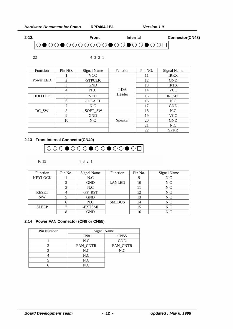
2-12. Front Internal Connector(CN48)
Function Pin NO. Signal Name Function Pin NO. Signal Name1 VCC 11 IRRX2 -STPCLK 12 GNDPower LED3 GND 13 IRTX4 N .C 14 VCC5 VCC 15 IR_SELHDD LED6 -IDEACT 16 N.C7 N.C
IrDAHeader
17 GND8 -SOFT_SW 18 N.CDC_SW9 GND 19 VCC
10 N.C 20 GND21 N.C
Speaker
22 SPKR
2.13 Front Internal Connector(CN49)
Function Pin No. Signal Name Function Pin No. Signal Name1 N.C 9 N.CKEYLOCK2 GND 10 N.C3 N.C 11 N.C4 -FP_RST
LANLED
12 N.CRESETS/W 5 GND 13 N.C
6 N.C 14 N.C7 -EXTSMI 15 N.CSLEEP8 GND
SM_BUS
16 N.C
2.14 Power FAN Connector (CN8 or CN55)
Signal NamePin NumberCN8 CN55
1 N.C GND2 FAN_CNTR FAN_CNTR3 N.C N.C4 N.C5 N.C6 N.C
22 4 3 2 1
16 15 4 3 2 1
Hardware Document for Como RPR404-1B1 Version 1.0
Board Development Team - 13 - Updated : May 6. 1998
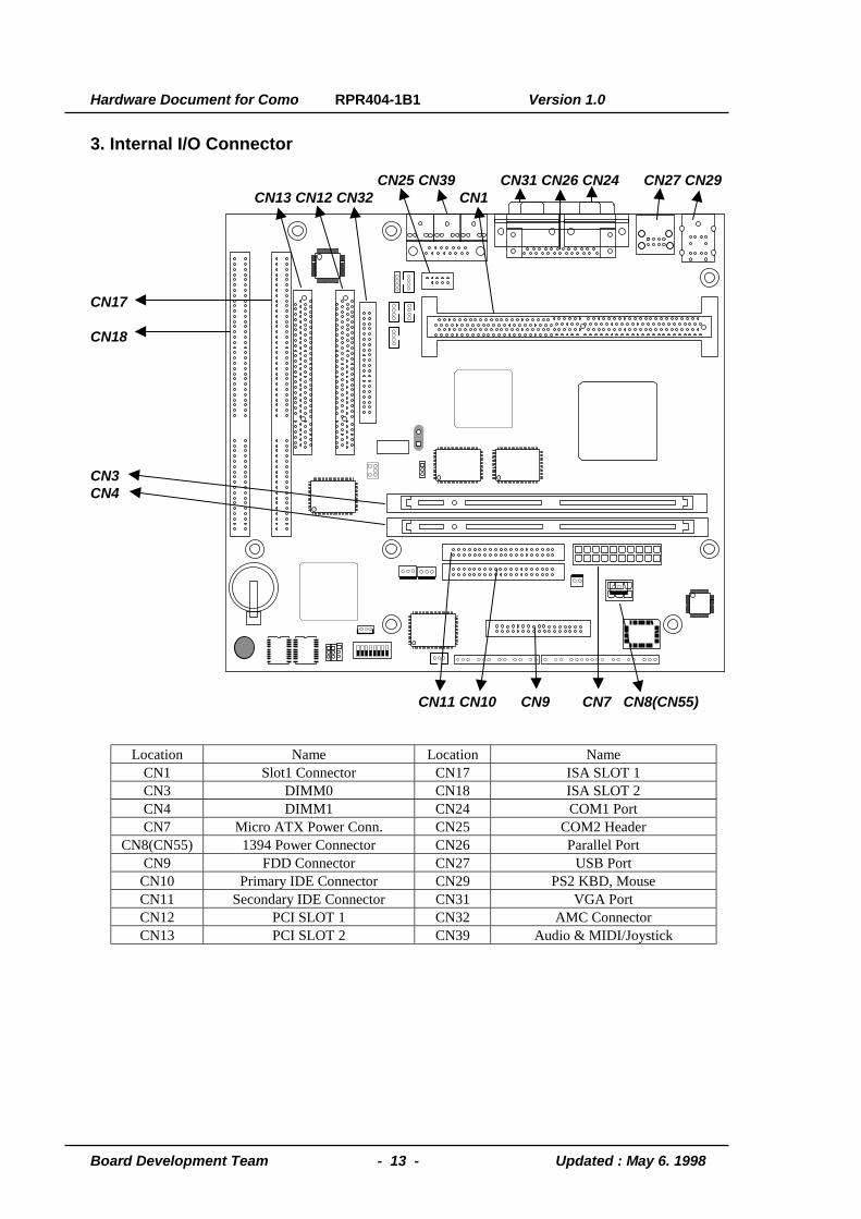
3. Internal I/O Connector
CN25 CN39 CN31 CN26 CN24 CN27 CN29CN13 CN12 CN32 CN1
CN17
CN18
CN3CN4
CN11 CN10 CN9 CN7 CN8(CN55)
Location Name Location NameCN1 Slot1 Connector CN17 ISA SLOT 1CN3 DIMM0 CN18 ISA SLOT 2CN4 DIMM1 CN24 COM1 PortCN7 Micro ATX Power Conn. CN25 COM2 Header
CN8(CN55) 1394 Power Connector CN26 Parallel PortCN9 FDD Connector CN27 USB Port
CN10 Primary IDE Connector CN29 PS2 KBD, MouseCN11 Secondary IDE Connector CN31 VGA PortCN12 PCI SLOT 1 CN32 AMC ConnectorCN13 PCI SLOT 2 CN39 Audio & MIDI/Joystick