micom-3f/3t/3r hf-ssb transceiversvdf.virginia.gov/pdf/training/command and control support...
TRANSCRIPT
Owner’s GuidePart I - Operation & Installation
6886867J01A
MICOM-3F/3T/3R
HF-SSB Transceivers
Downloaded from www.Manualslib.com manuals search engine


MICOM-3F/3T/3R HF-SSB Transceivers
MOBAT USA 1720 West Paul Dirac Drive Tallahassee, 32310 FL United States of America
Owners Guide Part I Operation & Installation
Cat. No. 6886867J01A
Downloaded from www.Manualslib.com manuals search engine

Table of Contents
Table of Contents Page
Introduction .....................................................................................................................1 MICOM-3 HF-SSB Radio Features......................................................................2 MICOM-3 Options and Accessories....................................................................3
Familiarization with MICOM-3 Radios ..............................................................................4 MICOM-3F Front Panel......................................................................................4 MICOM-3T Front Panel......................................................................................5 MICOM-3R Front Panel .....................................................................................6 Rear Panel (All Models) ......................................................................................7 LCD Display Functions .......................................................................................8 General Procedures............................................................................................10 Using the External (USB) Keyboard Option (MICOM-3F/3R only) .......................13 The Menu ..........................................................................................................14
Basic Operating Instructions .............................................................................................16 Turning the Radio On and Off............................................................................16 Transmitting and Receiving.................................................................................17 Using the Channel Mode....................................................................................18 Using the Frequency Mode ................................................................................22 Using the Scan Mode .........................................................................................30 Using the BIT Mode ...........................................................................................31 Locking the Radio...............................................................................................32 Changing the Password.......................................................................................33
Using Automatic Link Establishment (ALE).........................................................................34 ALE Capabilities and Features.............................................................................34 Using ALE Functions in the Channel Mode .........................................................43 Entering the ALE Mode.......................................................................................43 Receiving and Transmitting Calls in ALE Mode....................................................45
Using the Programming Mode ..........................................................................................78 Programming the Radio Parameters ..................................................................................81
Programming Channels.......................................................................................82 Selecting Radio Parameters.................................................................................84 Setting Radio Options.........................................................................................86
ALE Programming .............................................................................................................87 Programming Nets..............................................................................................88 Setting the Net Options ......................................................................................90 Directory Parameters..........................................................................................90 AMD Message Configuration ..............................................................................91 ALE Options Configuration .................................................................................91 Auto Dial Parameters..........................................................................................93
i
Downloaded from www.Manualslib.com manuals search engine
MICOM-3F/3T/3R HF-SSB Owners Guide
Storing ALE parameters.......................................................................................93 Using the New Station Address Filter ..................................................................94
Using the VP-116 Mini Voice Privacy Unit........................................................................95 Introduction .......................................................................................................95 Specific Parameters for Privacy Operation ..........................................................95 Connecting/Disconnecting the VP-116 Unit........................................................95 Using the VP-116 Unit .......................................................................................96 Programming the VP-116 Unit from the MICOM-3 ............................................97
Using the Vocoder............................................................................................................100 Introduction .......................................................................................................100 Using the Vocoder..............................................................................................100 Programming the Vocoder..................................................................................102
Using the MICOM-3 GPS Receiver ...................................................................................104 Introduction .......................................................................................................104 GPS Receiver Functions......................................................................................104 GPS Antenna......................................................................................................105 Operating the GPS Receiver ...............................................................................106
Installation........................................................................................................................110 General ..............................................................................................................110 Base Station Installation ......................................................................................111 MICOM-3R Installation ......................................................................................112 MICOM-3F Installation.......................................................................................113 MICOM-3T Installation.......................................................................................113 Installation Procedures .......................................................................................115 Connectors.........................................................................................................120
Maintenance ....................................................................................................................124 Introduction .......................................................................................................124 Preventative Maintenance ..................................................................................124 Using BIT ...........................................................................................................125 Troubleshooting .................................................................................................127 Service ...............................................................................................................129
Appendix A micomTrooper 3 5-50 Watt HF-SSB Backpack Transceiver ...........................130 Introduction .......................................................................................................130 Preparing the micomTrooper 3 for Operation.....................................................134 Operating Instructions ........................................................................................140 Preparing micomTrooper 3 for Static Operation .................................................141 Using the micomTrooper 3 Battery Charger, FLN9541 .......................................142
List of Procedures .............................................................................................................144
ii
Downloaded from www.Manualslib.com manuals search engine
Acronyms
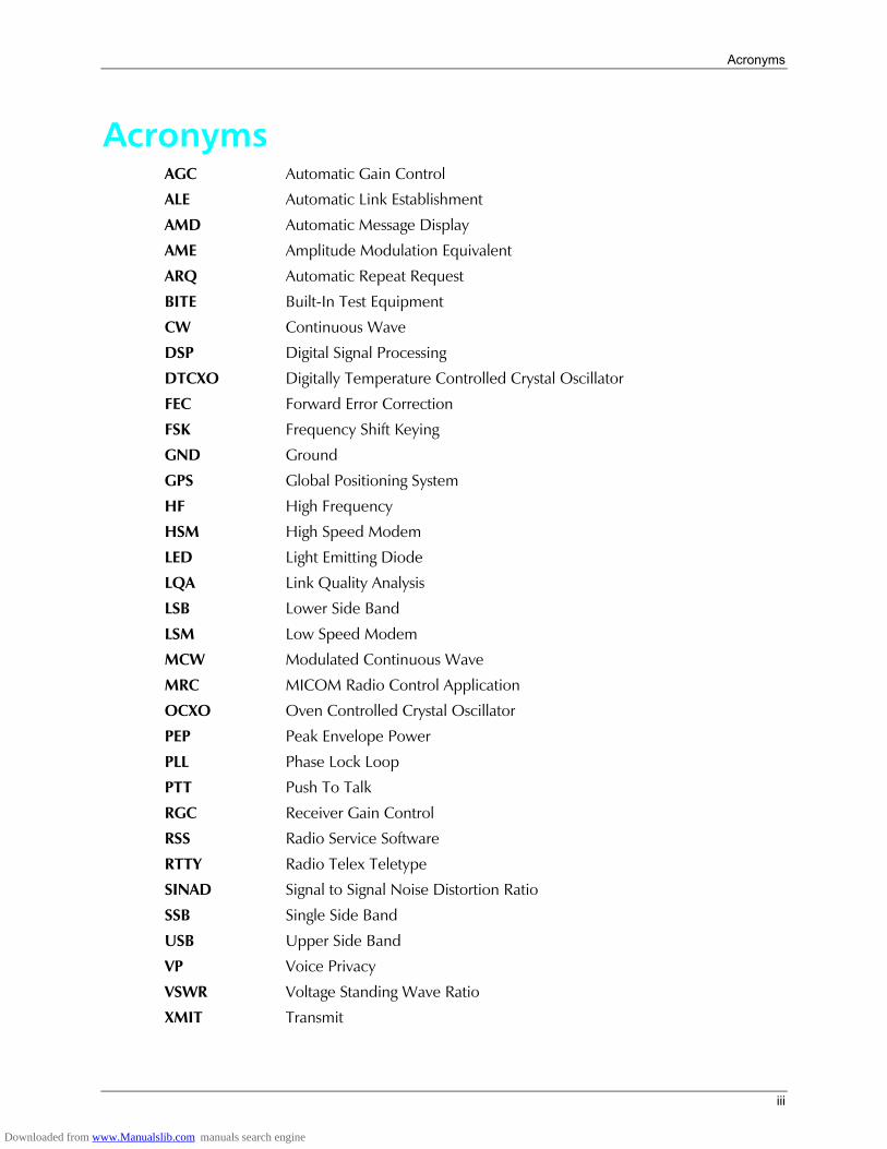
Acronyms AGC Automatic Gain Control
ALE Automatic Link Establishment
AMD Automatic Message Display
AME Amplitude Modulation Equivalent
ARQ Automatic Repeat Request
BITE Built-In Test Equipment
CW Continuous Wave
DSP Digital Signal Processing
DTCXO Digitally Temperature Controlled Crystal Oscillator
FEC Forward Error Correction
FSK Frequency Shift Keying
GND Ground
GPS Global Positioning System
HF High Frequency
HSM High Speed Modem
LED Light Emitting Diode
LQA Link Quality Analysis
LSB Lower Side Band
LSM Low Speed Modem
MCW Modulated Continuous Wave
MRC MICOM Radio Control Application
OCXO Oven Controlled Crystal Oscillator
PEP Peak Envelope Power
PLL Phase Lock Loop
PTT Push To Talk
RGC Receiver Gain Control
RSS Radio Service Software
RTTY Radio Telex Teletype
SINAD Signal to Signal Noise Distortion Ratio
SSB Single Side Band
USB Upper Side Band
VP Voice Privacy
VSWR Voltage Standing Wave Ratio
XMIT Transmit
iii
Downloaded from www.Manualslib.com manuals search engine
MICOM-3F/3T/3R HF-SSB Owners Guide
Performance Specifications
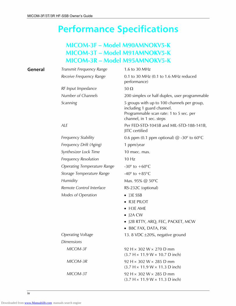
MICOM-3F Model M90AMNOKV5-K MICOM-3T Model M91AMNOKV5-K MICOM-3R Model M95AMNOKV5-K
General Transmit Frequency Range 1.6 to 30 MHz
Receive Frequency Range 0.1 to 30 MHz (0.1 to 1.6 MHz reduced performance)
RF Input Impedance 50 Ω
Number of Channels 200 simplex or half duplex, user programmable
Scanning 5 groups with up to 100 channels per group, including 1 guard channel. Programmable scan rate: 1 to 5 sec. per channel, in 1 sec. steps
ALE Per FED-STD-1045B and MIL-STD-188-141B, JITC certified
Frequency Stability 0.6 ppm (0.1 ppm optional) @ -30° to 60°C
Frequency Drift (Aging) 1 ppm/year
Synthesizer Lock Time 10 msec. max.
Frequency Resolution 10 Hz
Operating Temperature Range -30° to +60°C
Storage Temperature Range -40° to +85°C
Humidity Max. 95% @ 50°C
Remote Control Interface RS-232C (optional)
Modes of Operation • ]3E SSB
• R3E PILOT
• H3E AME
• J2A CW
• J2B RTTY, ARQ, FEC, PACKET, MCW
• B8C FAX, DATA, FSK
Operating Voltage 13. 8 VDC ±20%, negative ground
Dimensions
MICOM-3F 92 H × 302 W × 270 D mm (3.7 H × 11.9 W × 10.7 D inch)
MICOM-3R 92 H × 302 W × 285 D mm (3.7 H × 11.9 W × 11.3 D inch)
MICOM-3T 92 H × 302 W × 285 D mm (3.7 H × 11.9 W × 11.3 D inch)
iv
Downloaded from www.Manualslib.com manuals search engine
Performance Specifications
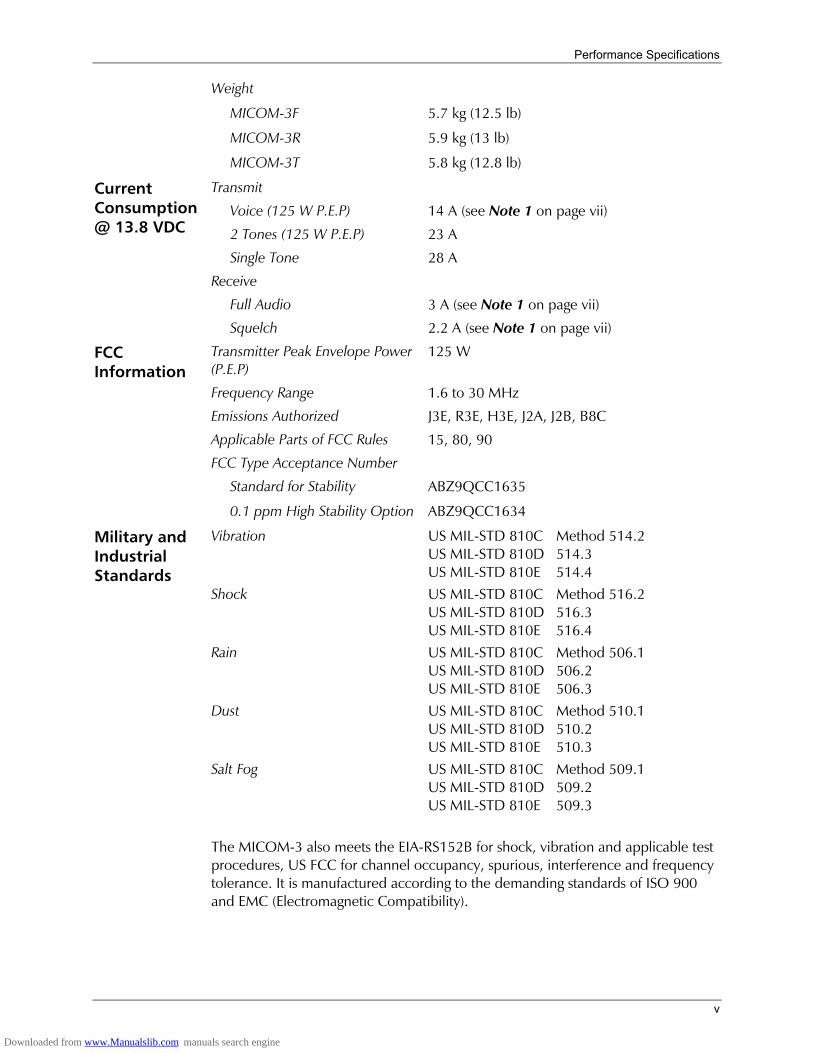
Weight
MICOM-3F 5.7 kg (12.5 lb)
MICOM-3R 5.9 kg (13 lb)
MICOM-3T 5.8 kg (12.8 lb)
Transmit
Voice (125 W P.E.P) 14 A (see Note 1 on page vii)
2 Tones (125 W P.E.P) 23 A
Single Tone 28 A
Receive
Full Audio 3 A (see Note 1 on page vii)
Current Consumption @ 13.8 VDC
Squelch 2.2 A (see Note 1 on page vii)
Transmitter Peak Envelope Power (P.E.P)
125 W
Frequency Range 1.6 to 30 MHz
Emissions Authorized J3E, R3E, H3E, J2A, J2B, B8C
Applicable Parts of FCC Rules 15, 80, 90
FCC Information
FCC Type Acceptance Number
Standard for Stability ABZ9QCC1635
0.1 ppm High Stability Option ABZ9QCC1634
Vibration US MIL-STD 810C Method 514.2 US MIL-STD 810D 514.3 US MIL-STD 810E 514.4
Shock US MIL-STD 810C Method 516.2 US MIL-STD 810D 516.3 US MIL-STD 810E 516.4
Military and Industrial Standards
Rain US MIL-STD 810C Method 506.1 US MIL-STD 810D 506.2 US MIL-STD 810E 506.3
Dust US MIL-STD 810C Method 510.1 US MIL-STD 810D 510.2 US MIL-STD 810E 510.3
Salt Fog US MIL-STD 810C Method 509.1 US MIL-STD 810D 509.2 US MIL-STD 810E 509.3
The MICOM-3 also meets the EIA-RS152B for shock, vibration and applicable test procedures, US FCC for channel occupancy, spurious, interference and frequency tolerance. It is manufactured according to the demanding standards of ISO 900 and EMC (Electromagnetic Compatibility).
v
Downloaded from www.Manualslib.com manuals search engine
MICOM-3F/3T/3R HF-SSB Owners Guide
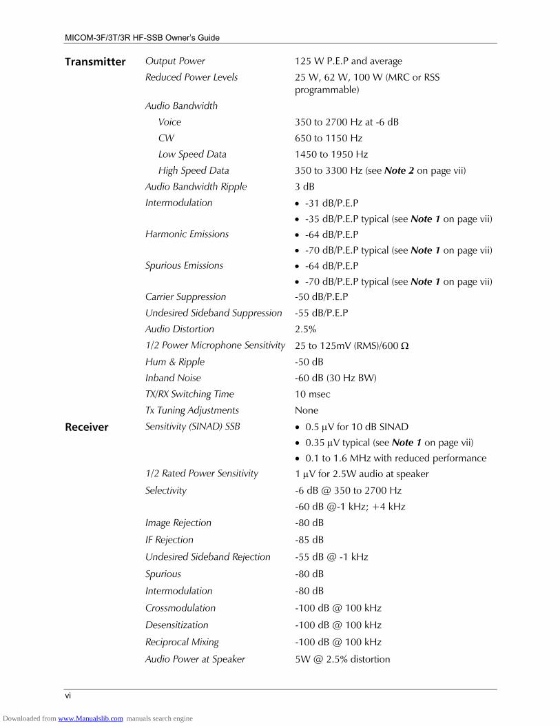
Output Power 125 W P.E.P and average
Reduced Power Levels 25 W, 62 W, 100 W (MRC or RSS programmable)
Audio Bandwidth
Voice 350 to 2700 Hz at -6 dB
CW 650 to 1150 Hz
Low Speed Data 1450 to 1950 Hz
High Speed Data 350 to 3300 Hz (see Note 2 on page vii)
Audio Bandwidth Ripple 3 dB
Intermodulation • -31 dB/P.E.P
• -35 dB/P.E.P typical (see Note 1 on page vii) Harmonic Emissions • -64 dB/P.E.P
• -70 dB/P.E.P typical (see Note 1 on page vii) Spurious Emissions • -64 dB/P.E.P
• -70 dB/P.E.P typical (see Note 1 on page vii) Carrier Suppression -50 dB/P.E.P
Undesired Sideband Suppression -55 dB/P.E.P
Audio Distortion 2.5%
1/2 Power Microphone Sensitivity 25 to 125mV (RMS)/600 Ω
Hum & Ripple -50 dB
Inband Noise -60 dB (30 Hz BW)
TX/RX Switching Time 10 msec
Transmitter
Tx Tuning Adjustments None
Receiver Sensitivity (SINAD) SSB • 0.5 µV for 10 dB SINAD
• 0.35 µV typical (see Note 1 on page vii)
• 0.1 to 1.6 MHz with reduced performance
1/2 Rated Power Sensitivity 1 µV for 2.5W audio at speaker
Selectivity -6 dB @ 350 to 2700 Hz
-60 dB @-1 kHz; +4 kHz
Image Rejection -80 dB
IF Rejection -85 dB
Undesired Sideband Rejection -55 dB @ -1 kHz
Spurious -80 dB
Intermodulation -80 dB
Crossmodulation -100 dB @ 100 kHz
Desensitization -100 dB @ 100 kHz
Reciprocal Mixing -100 dB @ 100 kHz
Audio Power at Speaker 5W @ 2.5% distortion
vi
Downloaded from www.Manualslib.com manuals search engine
Performance Specifications
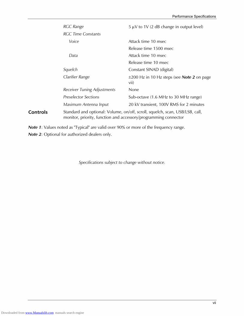
RGC Range 5 µV to 1V (2 dB change in output level)
RGC Time Constants
Voice Attack time 10 msec
Release time 1500 msec
Data Attack time 10 msec
Release time 10 msec
Squelch Constant SINAD (digital)
Clarifier Range ±200 Hz in 10 Hz steps (see Note 2 on page vii)
Receiver Tuning Adjustments None
Preselector Sections Sub-octave (1.6 MHz to 30 MHz range)
Maximum Antenna Input 20 kV transient, 100V RMS for 2 minutes
Controls Standard and optional: Volume, on/off, scroll, squelch, scan, USB/LSB, call, monitor, priority, function and accessory/programming connector
Note 1: Values noted as "Typical" are valid over 90% or more of the frequency range.
Note 2: Optional for authorized dealers only.
Specifications subject to change without notice.
vii
Downloaded from www.Manualslib.com manuals search engine
MICOM-3F/3T/3R HF-SSB Owners Guide
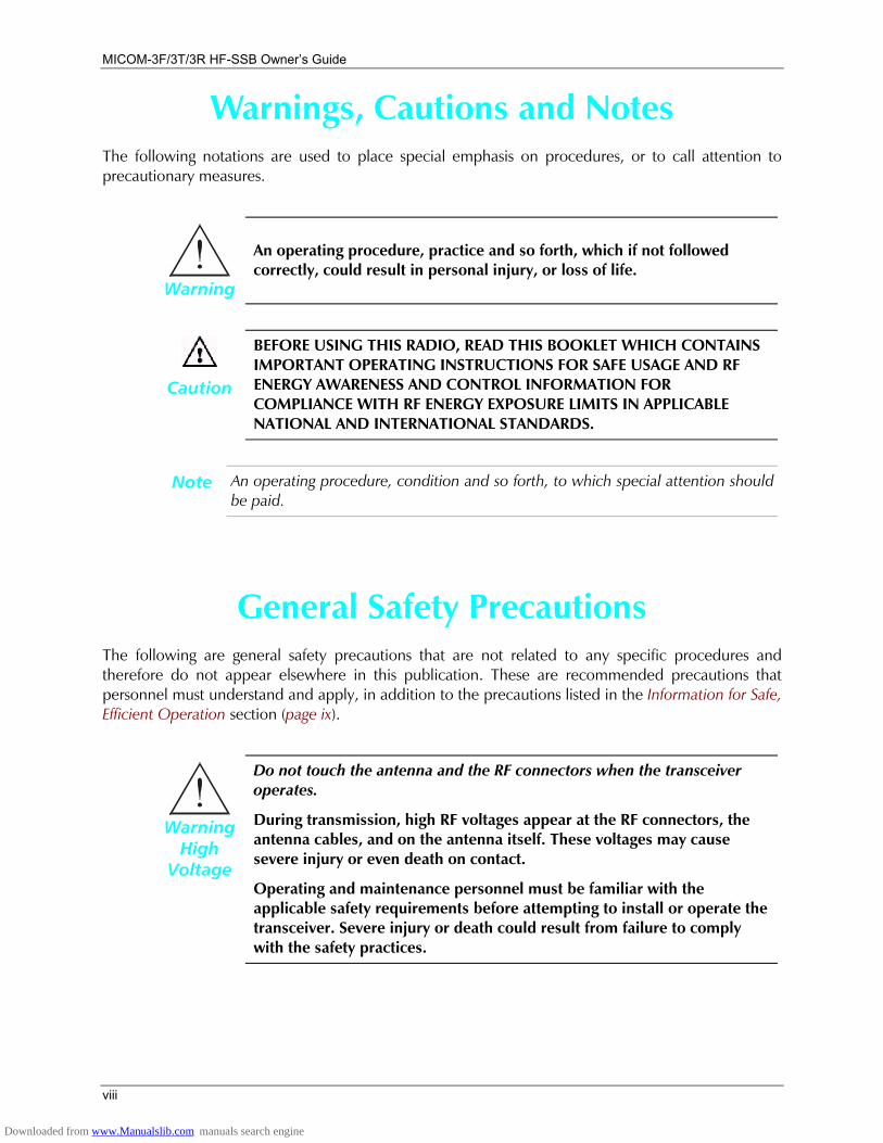
Warnings, Cautions and Notes The following notations are used to place special emphasis on procedures, or to call attention to precautionary measures.
Warning
An operating procedure, practice and so forth, which if not followed correctly, could result in personal injury, or loss of life.
Caution
BEFORE USING THIS RADIO, READ THIS BOOKLET WHICH CONTAINS IMPORTANT OPERATING INSTRUCTIONS FOR SAFE USAGE AND RF ENERGY AWARENESS AND CONTROL INFORMATION FOR COMPLIANCE WITH RF ENERGY EXPOSURE LIMITS IN APPLICABLE NATIONAL AND INTERNATIONAL STANDARDS.
Note An operating procedure, condition and so forth, to which special attention should be paid.
General Safety Precautions The following are general safety precautions that are not related to any specific procedures and therefore do not appear elsewhere in this publication. These are recommended precautions that personnel must understand and apply, in addition to the precautions listed in the Information for Safe, Efficient Operation section (page ix).
Warning High
Voltage
Do not touch the antenna and the RF connectors when the transceiver operates.
During transmission, high RF voltages appear at the RF connectors, the antenna cables, and on the antenna itself. These voltages may cause severe injury or even death on contact.
Operating and maintenance personnel must be familiar with the applicable safety requirements before attempting to install or operate the transceiver. Severe injury or death could result from failure to comply with the safety practices.
viii
Downloaded from www.Manualslib.com manuals search engine

Information for Safe, Efficient Operation
ix
Information for Safe, Efficient Operation
Product Safety and RF Exposure for Mobile Two-Way Radios Installed in Vehicles or as Fixed Site Control Stations
Caution
BEFORE USING THIS RADIO, READ THIS BOOKLET WHICH CONTAINS IMPORTANT OPERATING INSTRUCTIONS FOR SAFE USAGE AND RF ENERGY AWARENESS AND CONTROL INFORMATION FOR COMPLIANCE WITH RF ENERGY EXPOSURE LIMITS IN APPLICABLE NATIONAL AND INTERNATIONAL STANDARDS.
The information provided in this document supersedes the general safety information contained in user guides published prior to February 2002.
Compliance with RF Energy Exposure Standards NOTICE This radio is intended for use in occupational/controlled applications where users have
been made aware of the potentional for exposure and can exercise control over their exposure. This radio device is NOT authorized for general population, consumer or similar use.
MOBAT USA 1720 West Paul Dirac Drive Tallahassee, 32310 FL United States of America
Downloaded from www.Manualslib.com manuals search engine
MICOM-3F/3T/3R HF-SSB Owners Guide
x
Federal Communication Commission Regulations The FCC has established limits for safe exposure to radio frequency (RF) emissions from mobile two-way radios. The FCC requires manufacturers to demonstrate compliance with RF exposure limits before mobile two-way radios can be marketed in the U.S. When two-way radios are approved for occupational/controlled environment exposure limits, the FCC requires users to be fully aware of, and exercise control over, their exposure. Awareness and control of RF exposure can be accomplished by education or training through appropriate means such as information and instructions in user manuals or safety booklets, or other appropriate means. This user safety booklet includes useful information about RF exposure and helpful instructions on how to control your RF exposure.
Your two-way radio is designed and tested to comply with a number of national and international standards and guidelines (listed below) regarding human exposure to radio frequency electromagnetic energy. This radio complies with the IEEE (FCC) and ICNIRP exposure limits for occupational/controlled RF exposure environments at usage factors of up to 50% talk-50% listen. In terms of measuring RF energy for compliance with FCC exposure guidelines, your radio radiates measurable RF energy only while it is transmitting (during talking), not when it is receiving (listening) or in standby mode.
Your two-way radio complies with the following RF energy exposure standards and guidelines:
• United States Federal Communications Commission, Code of Federal Regulations; 47CFR part 2 sub-part J
• American National Standards Institute (ANSI) / Institute of Electrical and Electronic Engineers (IEEE) C95.1-1992
• Institute of Electrical and Electronic Engineers (IEEE) C95.1-1999 Edition
• International Commission on Non-Ionizing Radiation Protection (ICNIRP) 1998
• Ministry of Health (Canada) Safety Code 6: Limits of Human Exposure to Radiofrequency Electromagnetic Fields in the Frequency Range from 3 kHz to 300 GHz, 1999
• Australian Communications Authority Radiocommunications (Electromagnetic Radiation Human Exposure) Standard, 2001
• ANATEL, Brasil Regulatory Authority, Resolution 256 (April 11, 2001). Additional Requirements for SMR, Cellular and PCS Product Certification.
Downloaded from www.Manualslib.com manuals search engine
Information for Safe, Efficient Operation
xi
Compliance and Control Guidelines and Operating Instructions for Mobile Two-Way Radios Installed in Vehicles To control your exposure and ensure compliance with the occupational/controlled environment exposure limits, always adhere to the following procedures:
• To transmit (talk), push the Push-To-Talk (PTT) button; to receive, release the PTT button. Transmit only when people outside the vehicle are at least 7 feet from a properly installed, externally-mounted antenna.
• Install mobile antennas at the center of the roof or the center of the trunk deck per specific guidelines and instructions in the Radio Installation Manual. These mobile antenna installation guidelines are limited to metal body vehicles. Use only the approved, supplied antenna or an approved replacement antenna. Use of non-approved antennas, modifications, or attachments could damage the radio and may violate FCC regulations.
Downloaded from www.Manualslib.com manuals search engine
MICOM-3F/3T/3R HF-SSB Owners Guide
Compliance and Control Guidelines and Operating Instructions for Mobile Two-Way Radios Installed as Fixed Site Control Stations If mobile radio equipment is installed at a fixed location and operated as a control station or as a fixed unit, the antenna installation must comply with the following requirements in order to ensure optimal performance and compliance with the RF energy exposure limits in the standards and guidelines listed on page x:
• The antenna should be mounted outside the building on the roof or a tower if at all possible.
• As with all fixed site antenna installations, it is the responsibility of the licensee to manage the site in accordance with applicable regulatory requirements and may require additional compliance actions such as site survey measurements, signage, and site access restrictions in order to ensure that exposure limits are not exceeded.
Electromagnetic Interference/Compatibility Note Nearly every electronic device is susceptible to electromagnetic interference (EMI)
if inadequately shielded, designed, or otherwise configured for electromagnetic compatibility. It may be necessary to conduct compatibility testing to determine if any electronic equipment used in or around vehicles or near fixed site antenna is sensitive to external RF energy or if any procedures need to be followed to eliminate or mitigate the potential for interaction between the radio transmitter and the equipment or device.
Facilities To avoid electromagnetic interference and/or compatibility conflicts, turn off your radio In any facility where posted notices instruct you to do so. Hospitals or health care facilities may be using equipment that is sensitive to external RF energy.
Vehicles To avoid possible interaction between the radio transmitter and any vehicle electronic control modules, for example, ABS, engine, or transmission controls, the radio should be installed only by an experienced installer and that the following precautions be used when installing the radio:
1. Refer to the manufacturer's instructions or other technical bulletins for recommendations on radio installation.
2. Before installing the radio, determine the location of the electronic control modules and their harnesses in the vehicle.
3. Route all radio wiring, including the antenna transmission line, as far away as possible from the electronic control units and associated wiring.
xii
Downloaded from www.Manualslib.com manuals search engine
Information for Safe, Efficient Operation
Driver Safety Check the laws and regulations on the use of radios in the area where you drive. Always obey them.
When using your radio while driving, please: • Give full attention to driving and to the road.
• Pull off the road and park before making or answering a call if driving conditions so require.
Operational Warnings
Warning
For Vehicles with an Air Bag
Do not mount or place a mobile radio in the area over an air bag deployment area. Air bags inflate with great force. If a radio is placed in the air bag deployment area and the air bag inflates, the radio may be propelled with great force and cause serious injury to occupants of the vehicle.
Potentially Explosive Atmospheres Turn off your radio prior to entering any area with a potentially explosive atmosphere. Sparks in a potentially explosive atmosphere can cause an explosion or fire resulting in bodily injury or even death.
The areas with potentially explosive atmospheres include fueling areas such as below decks on boats, fuel or chemical transfer or storage facilities, and areas where the air contains chemicals or particles such as grain, dust or metal powders. Areas with potentially explosive atmospheres are often, but not always, posted.
Warning
Blasting Caps and Blasting Areas
To avoid possible interference with blasting operations, turn off warning your radio when you are near electrical blasting caps, in a blasting area, or in areas posted: "Turn off two-way radio". Obey all signs and instructions.
For radios installed in vehicles fueled by liquefied petroleum gas, refer to the (U.S.) National Fire Protection Association standard, NFPA 58, for storage, handling, and/or container information. For a copy of the LP-gas standard, NFPA 58, contact the National Fire Protection Association, One Battery Park, Quincy, MA.
xiii
Downloaded from www.Manualslib.com manuals search engine

MICOM-3F/3T/3R HF-SSB Owners Guide
Intentionally Left Blank
xiv
Downloaded from www.Manualslib.com manuals search engine
Introduction
1
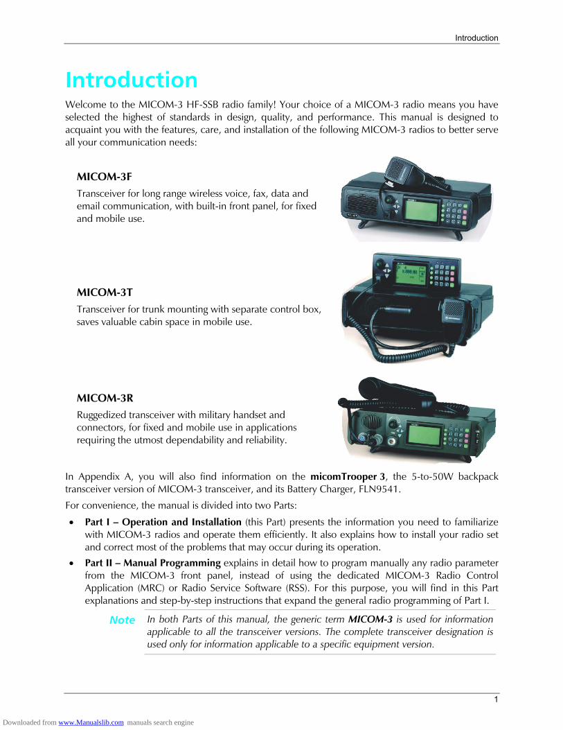
Introduction Welcome to the MICOM-3 HF-SSB radio family! Your choice of a MICOM-3 radio means you have selected the highest of standards in design, quality, and performance. This manual is designed to acquaint you with the features, care, and installation of the following MICOM-3 radios to better serve all your communication needs:
MICOM-3F Transceiver for long range wireless voice, fax, data and email communication, with built-in front panel, for fixed and mobile use.
MICOM-3T Transceiver for trunk mounting with separate control box, saves valuable cabin space in mobile use.
MICOM-3R Ruggedized transceiver with military handset and connectors, for fixed and mobile use in applications requiring the utmost dependability and reliability.
In Appendix A, you will also find information on the micomTrooper 3, the 5-to-50W backpack transceiver version of MICOM-3 transceiver, and its Battery Charger, FLN9541.
For convenience, the manual is divided into two Parts:
• Part I Operation and Installation (this Part) presents the information you need to familiarize with MICOM-3 radios and operate them efficiently. It also explains how to install your radio set and correct most of the problems that may occur during its operation.
• Part II Manual Programming explains in detail how to program manually any radio parameter from the MICOM-3 front panel, instead of using the dedicated MICOM-3 Radio Control Application (MRC) or Radio Service Software (RSS). For this purpose, you will find in this Part explanations and step-by-step instructions that expand the general radio programming of Part I.
Note In both Parts of this manual, the generic term MICOM-3 is used for information applicable to all the transceiver versions. The complete transceiver designation is used only for information applicable to a specific equipment version.
Downloaded from www.Manualslib.com manuals search engine
MICOM-3F/3T/3R HF-SSB Owners Guide
2
MICOM-3 HF-SSB Radio Features • Digital Signal Processing (DSP)
• Built-in Test Equipment (BITE)
• RF power indications
• 200 channel capacity, simplex or half-duplex
• Channel scan or Automatic Link Establishment (ALE) per MIL-STD-188-141B/FED-STD-1045
• MultiNet function for seamless integration of different HF radio networks in one network
• Automatic IF shift
• Clarifier
• Voice-activated digital squelch
• Excellent transmitter and receiver performance
• High frequency stability option
• DSP software can be upgraded to incorporate future options and new technologies
• Large LCD display and optional support for multiple languages
• MIL-STD-810C, D and E compliance.
Transmitter Features The maximum output power of the transmitter is 125 W PEP (Peak Envelope Power). The average transmission duty cycle is up to 1:4, thus enabling even CW (Continuous Wave) signals to be transmitted at the maximum available power. Output power can be preprogrammed to one of four levels: 25W, 62.5W, 100W and 125W. Accurate sensors are used to keep the output power at the selected value. The transmitter includes thermal protection. If, for any reason, the transmitter internal temperature exceeds the maximum permitted temperature, the output power is automatically reduced to avoid any fault due to excessive heat. Antenna mismatch protection is also included. If the VSWR (Voltage Standing Wave Ratio) rises to more than 2:1, the transmission will be inhibited to avoid damage and a message will be displayed.
Receiver Features The radio utilizes digital signal processing for implementing most of the receiver functions, e.g., demodulation, narrow band filtering, automatic gain control, noise blanking, tunable notch filter, squelch, etc. An automatic digital noise blanker is activated whenever repetitive noise (e.g., ignition spikes) is encountered in the received signal. The digital syllabic (speech identifier) squelch is activated whenever speech is identified, thus opening the audio path. However, if speech is not received, the audio path is muted, thus preventing background noise from disturbing the operator.
Frequency Sources Two types of frequency sources are available for the MICOM-3 radio. The standard 0.6 ppm DTCXO frequency source which assures a frequency accuracy of better than ±18 Hz. For frequencies lower than 10 MHz, it assures a frequency accuracy of better than ±6 Hz. When higher frequency accuracy is required, the G112 0.1 ppm OCXO frequency source can be ordered. It will assure a frequency accuracy of better than ±3 Hz at 30 MHz.
Downloaded from www.Manualslib.com manuals search engine
Introduction
3
Power Source The radio is designed for 13.8 V ±20% negative-ground operation and may be connected to a standard 12 V battery.
CW Keying Operation When the CW key is pressed, the radio transmits a continuous wave (at the full programmed power) and stops transmission when the key is released. CW keying operation is enabled by connecting a Morse key to the accessories connector. If you wish to operate CW keying with external headphones, the S809 Interface cable can be used, thus enabling a standard PL55 headphone and standard PL99 Morse key to be connected to the accessories connector.
Programmable Features The radio can be programmed using a PC running the MICOM Radio Control Application (MRC) or the Radio Service Software (RSS). The following radio features can be programmed:
• Up to 200 simplex/half duplex channels supporting SSB (J3E), AME (H3E), or Pilot (R3E) modes.
• Up to four levels of output power (up to 125W PEP and average).
• Five scanning groups of up to 200 channels, each with guard channel. For further details, refer to MICOM Radio Control Application Owners Guide, Publication 6886869J01, or to MICOM-3 HF-SSB Transceiver, RSS Users Guide, Publication 6886867J01.
MICOM-3 Options and Accessories • RS-232 remote control interface • Linear power amplifier interface • Phone patch interface • Data/fax modem interface • MRC or RSS for PC • High (0.1 ppm) frequency accuracy • micomLink • VP-116 voice privacy unit • HF vocoder unit • Internal GPS receiver • ISB operation • Desktop microphone • Automatic antenna tuners • Continuous duty data transmission kit • AC power supply • 500 W linear power amplifier • 1 kW linear power amplifier • Antennas and grounding • CW key and headphones • External speaker.
Downloaded from www.Manualslib.com manuals search engine
MICOM-3F/3T/3R HF-SSB Owners Guide
4
Familiarization with MICOM-3 Radios
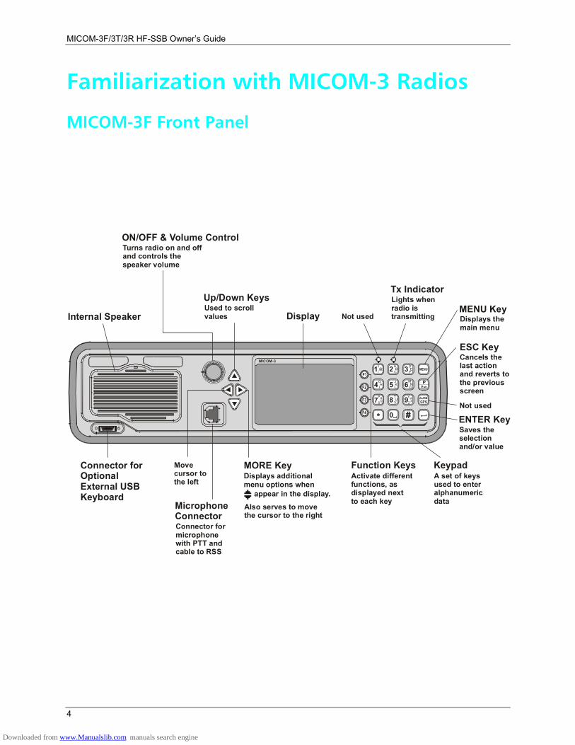
MICOM-3F Front Panel
MICOM-3
F1
F2
F4
F3
1?@/
G
P
H
R
I
S
4
7
*
Q
J MK NL O5 6TUV8 9
A DB E
C F2 3
0 #
YWZ X
MENU
EscP
GPSALARM
Cancels thelast actionand reverts tothe previous screen
Not used
Saves the selectionand/or value
ENTER Key
ESC Key
KeypadA set of keysused to enteralphanumericdata
Function KeysActivate differentfunctions, asdisplayed nextto each keyMicrophone
ConnectorConnector formicrophone with PTT andcable to RSS
Connector forOptionalExternal USBKeyboard
Movecursor tothe left
MORE KeyDisplays additionalmenu options when
appear in the display.ÛAlso serves to movethe cursor to the right
Displays the main menu
DisplayInternal Speaker
Tx IndicatorLights whenradio istransmitting
Up/Down KeysUsed to scrollvalues
ON/OFF & Volume ControlTurns radio on and offand controls thespeaker volume
Not usedMENU Key
Downloaded from www.Manualslib.com manuals search engine
Familiarization with MICOM-3 Radios
5
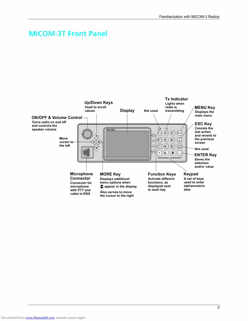
MICOM-3T Front Panel
MICOM-3
1?@
/
G
P
H
R
I
S
4
7
*
Q
J MK NL O5 6TUV8 9
A DB E
C F2 3
0 #
YWZX
MENU
EscP
GPSALARM
F1
F2
F4
F3
Cancels thelast actionand reverts tothe previous screen
Not used
Saves the selectionand/or value
ENTER Key
ESC Key
KeypadA set of keysused to enteralphanumericdata
Function KeysActivate differentfunctions, asdisplayed nextto each key
Microphone ConnectorConnector formicrophone with PTT andcable to RSS
Movecursor tothe left
Displays the main menu
Display
Tx IndicatorLights whenradio istransmitting
Up/Down KeysUsed to scrollvalues
ON/OFF & Volume ControlTurns radio on and offand controls thespeaker volume
Not usedMENU Key
MORE KeyDisplays additionalmenu options when
appear in the display.Also serves to movethe cursor to the right
Û
Downloaded from www.Manualslib.com manuals search engine
MICOM-3F/3T/3R HF-SSB Owners Guide
6
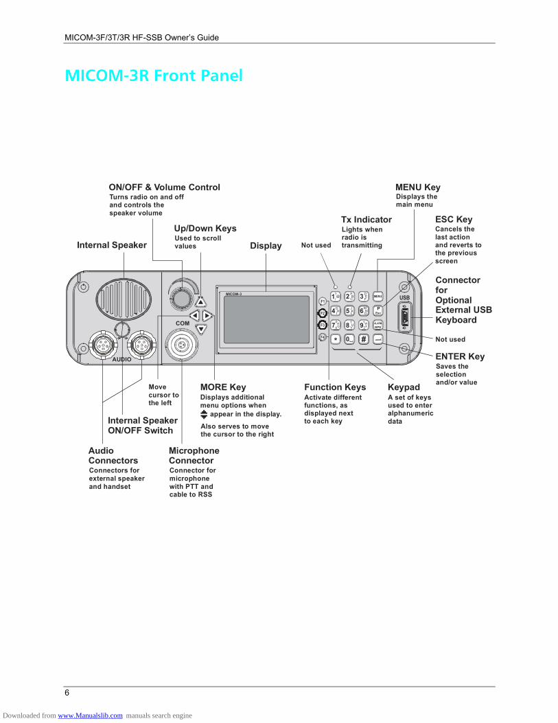
MICOM-3R Front Panel
AUDIO
COM
MICOM-3USB1?@
/
G
P
H
R
I
S
4
7
*
Q
J MK NL O5 6TUV8 9
A DB E
C F2 3
0 #
YWZX
MENU
EscP
GPSALARM
F1
F2
F4
F3
Not used
Saves the selectionand/or value
ENTER Key
Cancels thelast actionand reverts tothe previous screen
ESC Key
KeypadA set of keysused to enteralphanumericdata
Function KeysActivate differentfunctions, asdisplayed nextto each key
Microphone ConnectorConnector formicrophone with PTT andcable to RSS
Audio ConnectorsConnectors forexternal speakerand handset
Connector for OptionalExternal USBKeyboard
Movecursor tothe left
Internal Speaker
Internal SpeakerON/OFF Switch
Display
Tx IndicatorLights whenradio istransmitting
Up/Down KeysUsed to scrollvalues
ON/OFF & Volume ControlTurns radio on and offand controls thespeaker volume
Not used
Displays the main menu
MENU Key
MORE KeyDisplays additionalmenu options when
appear in the display.Also serves to movethe cursor to the right
Û
Downloaded from www.Manualslib.com manuals search engine
Familiarization with MICOM-3 Radios
7
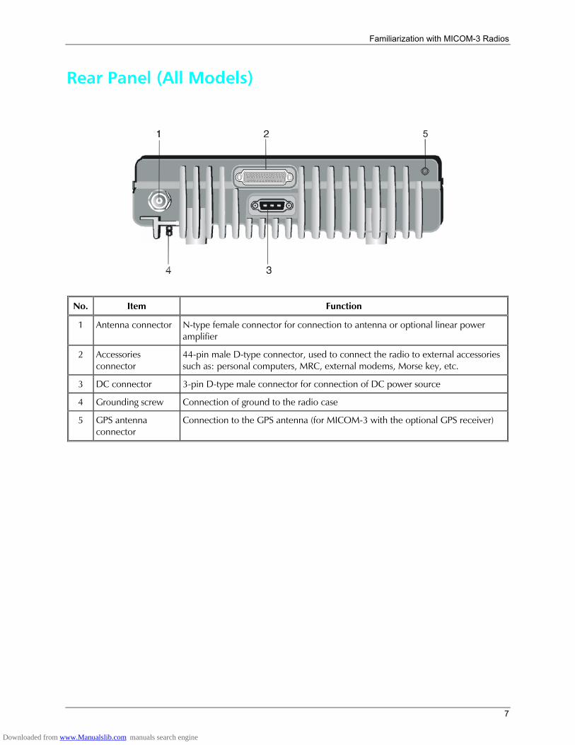
Rear Panel (All Models)
5
No. Item Function
1 Antenna connector N-type female connector for connection to antenna or optional linear power amplifier
2 Accessories connector
44-pin male D-type connector, used to connect the radio to external accessories such as: personal computers, MRC, external modems, Morse key, etc.
3 DC connector 3-pin D-type male connector for connection of DC power source
4 Grounding screw Connection of ground to the radio case
5 GPS antenna connector
Connection to the GPS antenna (for MICOM-3 with the optional GPS receiver)
Downloaded from www.Manualslib.com manuals search engine
MICOM-3F/3T/3R HF-SSB Owners Guide
8
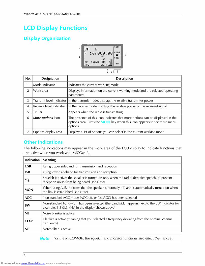
LCD Display Functions
Display Organization MICOM-3
PWR
MODE
AGC
BW
CH 6F 16,000.00
NFUSB NBCLAR
I
7
1
26
SQ BW3.3AGC
53 4
No. Designation Description
1 Mode indicator Indicates the current working mode
2 Work area Displays information on the current working mode and the selected operating parameters
3 Transmit level indicator In the transmit mode, displays the relative transmitter power
4 Receive level indicator In the receive mode, displays the relative power of the received signal
5 Tx Bar Appears when the radio is transmitting
6 More options icon The presence of this icon indicates that more options can be displayed in the options area. Press the MORE key when this icon appears to see more menu options
7 Options display area Displays a list of options you can select in the current working mode
Other Indications The following indications may appear in the work area of the LCD display to indicate functions that are active when you work with MICOM-3.
Indication Meaning
USB Using upper sideband for transmission and reception
LSB Using lower sideband for transmission and reception
SQ Squelch is active: the speaker is turned on only when the radio identifies speech, to prevent reception noise from being heard (see Note)
MON When using ALE, indicates that the speaker is normally off, and is automatically turned on when the link is established (see Note)
AGC Non-standard AGC mode (AGC off, or fast AGC) has been selected
BW Non-standard bandwidth has been selected (the bandwidth appears next to the BW indicator for example, 3.3 (3.3 kHz) in the display shown above)
NB Noise blanker is active
CLAR Clarifier is active (meaning that you selected a frequency deviating from the nominal channel frequency)
NF Notch filter is active
Note For the MICOM-3R, the squelch and monitor functions also effect the handset.
Downloaded from www.Manualslib.com manuals search engine
Familiarization with MICOM-3 Radios
9
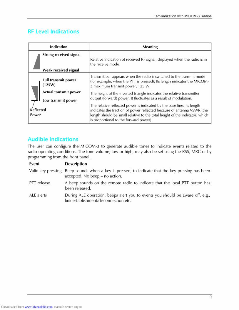
RF Level Indications
Indication Meaning
Strong received signal
Weak received signal
Relative indication of received RF signal, displayed when the radio is in the receive mode
Full transmit power (125W)
Actual transmit power
Low transmit power
Transmit bar appears when the radio is switched to the transmit mode (for example, when the PTT is pressed). Its length indicates the MICOM-3 maximum transmit power, 125 W.
The height of the inverted triangle indicates the relative transmitter output (forward) power. It fluctuates as a result of modulation.
The relative reflected power is indicated by the base line: its length indicates the fraction of power reflected because of antenna VSWR (the length should be small relative to the total height of the indicator, which is proportional to the forward power)
Audible Indications The user can configure the MICOM-3 to generate audible tones to indicate events related to the radio operating conditions. The tone volume, low or high, may also be set using the RSS, MRC or by programming from the front panel.
Event Description
Valid key pressing Beep sounds when a key is pressed, to indicate that the key pressing has been accepted. No beep no action.
PTT release A beep sounds on the remote radio to indicate that the local PTT button has been released.
ALE alerts During ALE operation, beeps alert you to events you should be aware off, e.g., link establishment/disconnection etc.
Reflected Power
Downloaded from www.Manualslib.com manuals search engine
MICOM-3F/3T/3R HF-SSB Owners Guide
10
General Procedures This section provides general procedures that will help you start using your MICOM-3 radio and get the most of its advanced features.
Most of the activities that can be performed by you (selection of operating mode, status display, programming, testing, etc.) are done using the keypad together with the four navigation keys (up, down, left and right) and the front panel display.
To simplify operation, MICOM-3 uses soft keys that let you control the radio simply and efficiently, using a menu-driven mode that guides you and helps you make the required selections.
Menu-driven simply means that whenever you must select a parameter, an operating mode, etc., you select it from a list of allowed values displayed on the front panel display, thereby reducing the chance of error:
• To make the selection, you use navigation keys to reach the desired parameter value or operation, and then confirm the selection by pressing the ENTER key.
• To let you go back to previous options, there is an ESC key.
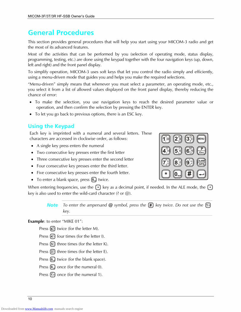
Using the Keypad Each key is imprinted with a numeral and several letters. These characters are accessed in clockwise order, as follows:
• A single key press enters the numeral
• Two consecutive key presses enter the first letter
• Three consecutive key presses enter the second letter
• Four consecutive key presses enter the third letter.
• Five consecutive key presses enter the fourth letter.
• To enter a blank space, press 0 twice.
1?@/
G
P
H
R
I
S
4
7
*
Q
J MK NL O5 6TUV8 9
A DB EC F2 3
0 #
YWZX
MENU
EscP
GPSALARM
When entering frequencies, use the * key as a decimal point, if needed. In the ALE mode, the * key is also used to enter the wild-card character (? or @).
Note To enter the ampersand @ symbol, press the # key twice. Do not use the 1?@
/ key.
Example: to enter MIKE 01:
Press MN
O6 twice (for the letter M).
Press GHI4 four times (for the letter I).
Press JKL5 three times (for the letter K).
Press DE
F3 three times (for the letter E).
Press 0 twice (for the blank space).
Press 0 once (for the numeral 0).
Press 1?@
/ once (for the numeral 1).
Downloaded from www.Manualslib.com manuals search engine

Familiarization with MICOM-3 Radios
11
Function Keys The function keys F1, F2, F3 and F4 appearing next to the display are soft keys used to select options which depend on the current radio mode. The current function of each key is shown in the options area of the display, next to the key. For example, on the PROG screen you can press F2 to start programming the ALE parameters.
If a certain function key is not used, no label appears next to the key (see for example F4), and pressing that key has no effect.
MICOM-3
RAD
ALE
LANG
PROG F1
F2
F4
F3
Scroll (MORE) Key The MORE key is used to scroll the options appearing in the options area of the display.
Up/Down Scroll Keys The up and down scroll keys are used to scroll between values that are already programmed into the radio. For example:
• In the Channel mode, pressing the up or down scroll key once lets you view the previous, respectively next, programmed channel. Pressing either key continuously scrolls the channels in the selected direction.
• In the Frequency mode, you can change the frequency in the corresponding direction.
• In the radio Programming mode, you can use these keys to scroll among the programmable parameters.
Up
More
Down
Selection from List of Predetermined Values When the parameter you want to select can assume only one of several predetermined values, you select the desired value by pressing the function keys:
• F1 enters the lowest possible value (or OFF)
• F4 enters the highest possible value
• F2 and F3 increment or decrement the value. When you reach either end, the corresponding key disappears
MICOM-3
PROGADT - 9 SEC
1
<--
-->
10
You cannot use the keypad to enter a value for such parameters.
Toggle Mode When the function being set can only be toggled on or off, one function key will be marked YES and another NO.
To expedite turning on and off often-used functions (for example, turn the squelch on or off) only one key is used. In this case, just press the key assigned to the function to be toggled: the new state is shown for a few seconds, and then disappears as it takes effect immediately.
MICOM-3
PROGALE - NO
YES
NO
Downloaded from www.Manualslib.com manuals search engine
MICOM-3F/3T/3R HF-SSB Owners Guide
12
Alphanumeric Edit Mode When you need to enter an alphanumeric string in a field, or edit a string, you type the desired alphanumeric character on the keypad. A blinking cursor _ indicates the location being edited.
In addition, the following function keys are available:
SAVE (F1) Saves editing changes (equivalent to pressing the ENTER key).
<−− (F2)
−−> (F3)
Used to move the cursor backwards and forwards. When you reach either end, the corresponding key disappears.
CLR (F4) Pressing this key momentarily erases the digit/letter at which the cursor is presently located, and shifts the entire field one place to the left.
Press this key continuously clears the entire field.
Numeric Edit Mode When you need to enter a number in a field, or edit the number, you type the desired digits on the keypad. A blinking cursor _ indicates the location being edited.
In addition, the following function keys are available:
BACK (F3) Erases the last digit.
CLR (F4) Erases all newly entered digits and restores the original value.
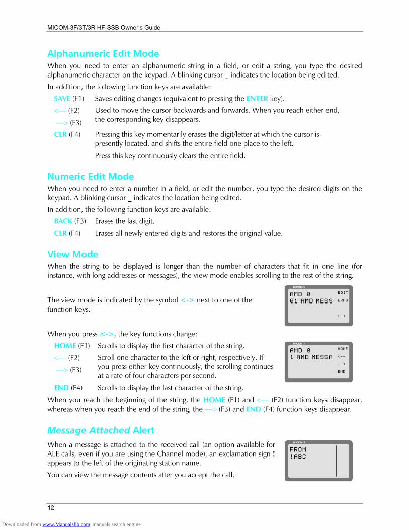
View Mode When the string to be displayed is longer than the number of characters that fit in one line (for instance, with long addresses or messages), the view mode enables scrolling to the rest of the string.
The view mode is indicated by the symbol <-> next to one of the function keys.
MICOM-3
EDIT
ERAS
<->
AMD 001 AMD MESS
When you press <->, the key functions change:
HOME (F1) Scrolls to display the first character of the string.
<−− (F2)
−−> (F3)
Scroll one character to the left or right, respectively. If you press either key continuously, the scrolling continues at a rate of four characters per second.
END (F4) Scrolls to display the last character of the string.
MICOM-3
HOME
<--
-->
END
AMD 01 AMD MESSA
When you reach the beginning of the string, the HOME (F1) and <−− (F2) function keys disappear, whereas when you reach the end of the string, the −−> (F3) and END (F4) function keys disappear.
Message Attached Alert When a message is attached to the received call (an option available for ALE calls, even if you are using the Channel mode), an exclamation sign ! appears to the left of the originating station name.
You can view the message contents after you accept the call.
MICOM-3
FROM!ABC
Downloaded from www.Manualslib.com manuals search engine
Familiarization with MICOM-3 Radios
13
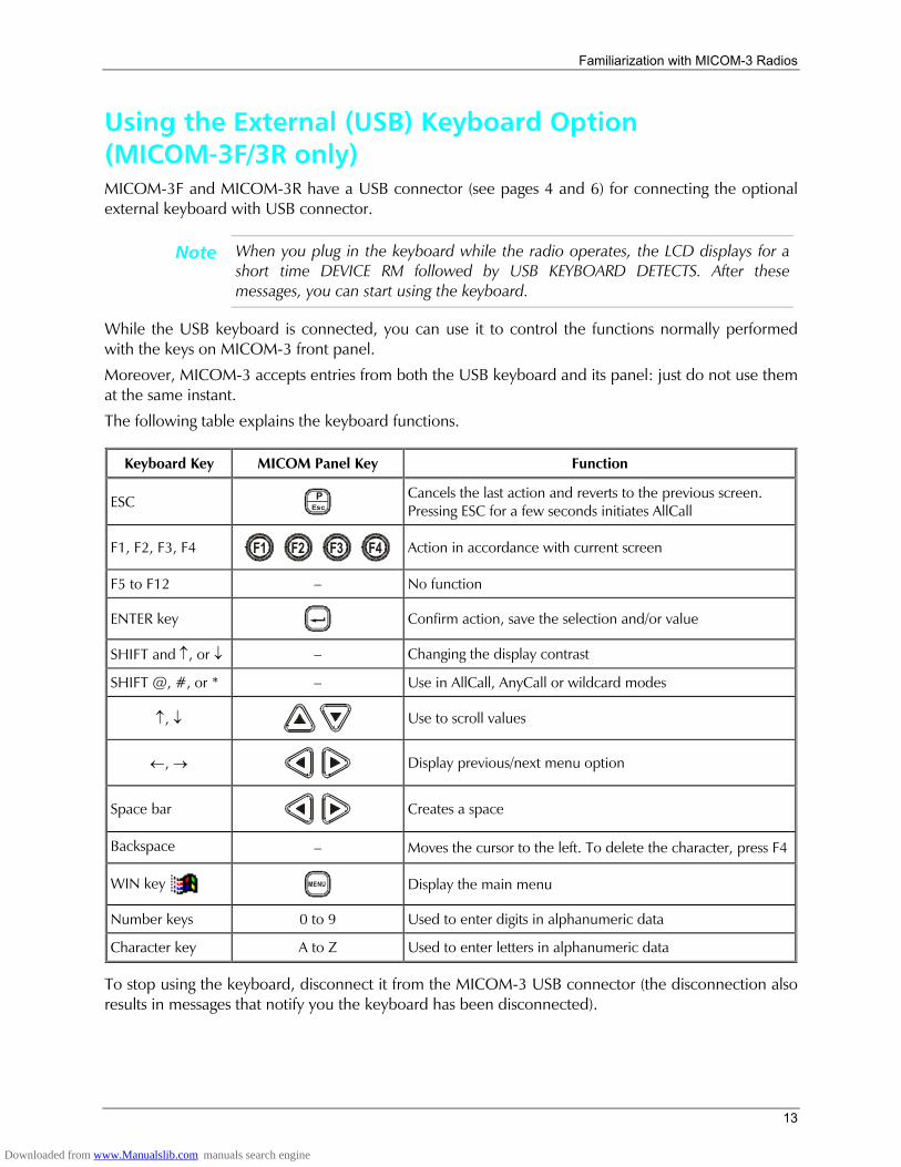
Using the External (USB) Keyboard Option (MICOM-3F/3R only) MICOM-3F and MICOM-3R have a USB connector (see pages 4 and 6) for connecting the optional external keyboard with USB connector.
Note When you plug in the keyboard while the radio operates, the LCD displays for a short time DEVICE RM followed by USB KEYBOARD DETECTS. After these messages, you can start using the keyboard.
While the USB keyboard is connected, you can use it to control the functions normally performed with the keys on MICOM-3 front panel.
Moreover, MICOM-3 accepts entries from both the USB keyboard and its panel: just do not use them at the same instant.
The following table explains the keyboard functions.
Keyboard Key MICOM Panel Key Function
ESC EscP
Cancels the last action and reverts to the previous screen. Pressing ESC for a few seconds initiates AllCall
F1, F2, F3, F4 F1
F2
F3
F4
Action in accordance with current screen
F5 to F12 No function
ENTER key
Confirm action, save the selection and/or value
SHIFT and ↑, or ↓ Changing the display contrast
SHIFT @, #, or * Use in AllCall, AnyCall or wildcard modes
↑, ↓
Use to scroll values
←, →
Display previous/next menu option
Space bar
Creates a space
Backspace Moves the cursor to the left. To delete the character, press F4
WIN key MENU
Display the main menu
Number keys 0 to 9 Used to enter digits in alphanumeric data
Character key A to Z Used to enter letters in alphanumeric data
To stop using the keyboard, disconnect it from the MICOM-3 USB connector (the disconnection also results in messages that notify you the keyboard has been disconnected).
Downloaded from www.Manualslib.com manuals search engine
MICOM-3F/3T/3R HF-SSB Owners Guide
14
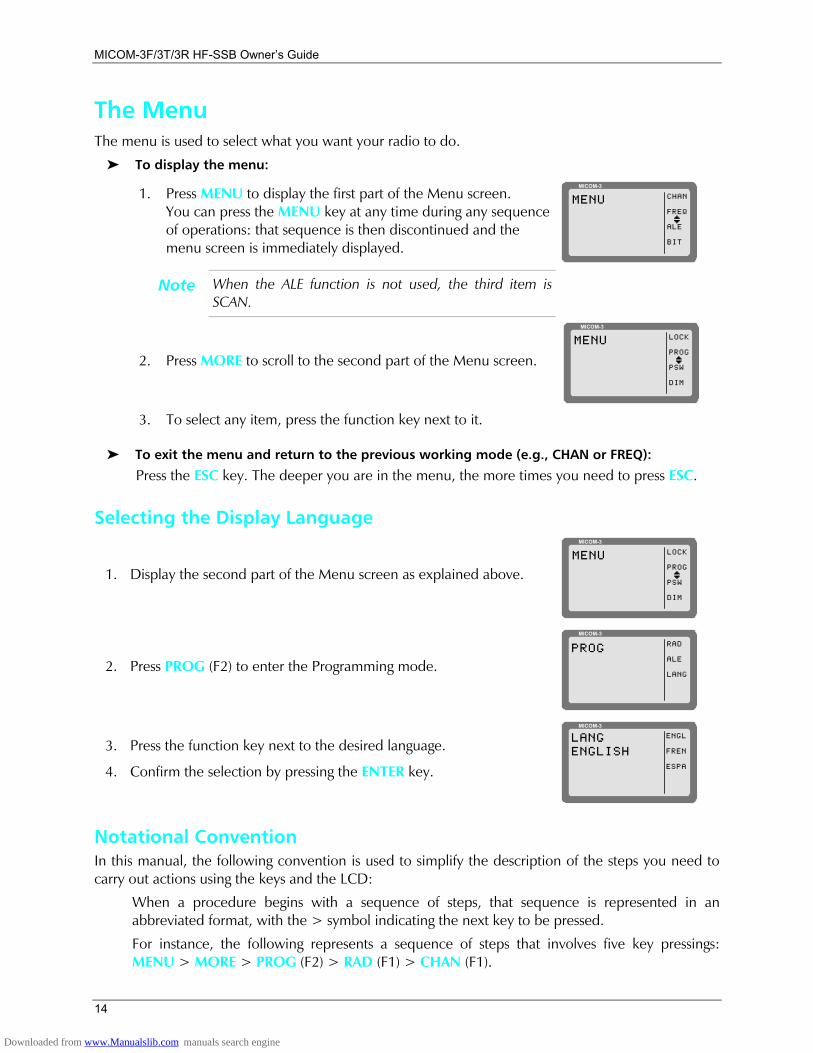
The Menu The menu is used to select what you want your radio to do.
To display the menu:
1. Press MENU to display the first part of the Menu screen. You can press the MENU key at any time during any sequence of operations: that sequence is then discontinued and the menu screen is immediately displayed.
MICOM-3
CHAN
FREQ
ALE
BIT
MENU
I
Note When the ALE function is not used, the third item is SCAN.
2. Press MORE to scroll to the second part of the Menu screen.
MICOM-3
LOCK
PROG
PSW
DIM
MENU
I
3. To select any item, press the function key next to it.
To exit the menu and return to the previous working mode (e.g., CHAN or FREQ):
Press the ESC key. The deeper you are in the menu, the more times you need to press ESC.
Selecting the Display Language
1. Display the second part of the Menu screen as explained above.
MICOM-3
LOCK
PROG
PSW
DIM
MENU
I
2. Press PROG (F2) to enter the Programming mode.
MICOM-3
RAD
ALE
LANG
PROG
3. Press the function key next to the desired language.
4. Confirm the selection by pressing the ENTER key.
MICOM-3
LANGENGLISH
ENGL
FREN
ESPA
Notational Convention In this manual, the following convention is used to simplify the description of the steps you need to carry out actions using the keys and the LCD:
When a procedure begins with a sequence of steps, that sequence is represented in an abbreviated format, with the > symbol indicating the next key to be pressed.
For instance, the following represents a sequence of steps that involves five key pressings: MENU > MORE > PROG (F2) > RAD (F1) > CHAN (F1).
Downloaded from www.Manualslib.com manuals search engine

Familiarization with MICOM-3 Radios
15
What you can Select Use the following description with Figure 1, which shows the details of the main menu. Additional options are available for a MICOM-3 with the GPS receiver option (see the Using the MICOM-3 GPS Receiver section starting on page 104).
Menu item ... and its purpose
CHAN Channel mode: the radio uses a set of preset parameters. Up to 200 sets of parameters can be defined and stored in the MICOM-3 where each set is assigned a channel number (1 to 200). You can use Figure 2 (page 21) to find details on the selections available on the CHAN menu.
FREQ Frequency mode: you can select manually the frequency and the other parameters to be used. You can use Figure 3 (page 27) to find details on the selections available on the FREQ menu.
ALE ALE mode: when you want to call other radio, the radio automatically sets up a link on the best free frequency that can be found. The sets of parameters needed for this operation mode are stored under net numbers (1 to 20).
SCAN SCAN mode: when ALE is not used, you can define a set of channels to be scanned before starting a call. The scan parameters are always loaded with the MRC together with the other operational parameters, but cannot be changed using the MICOM-3 panel.
BIT BIT mode: lets you check that the MICOM-3 is OK.
LOCK Lock the radio to prevent unauthorized use. To lock and unlock, you enter a password.
PROG Programming mode: lets you program (select and store) the required parameters. You can use Figure 6 (page 79) and Figure 7 (page 80) to find details on the selections available on the PROG menu.
DIM
1234
LEVEL0 1 2 3
CHAN FREQ
FULLCHANL.RF
BIT
LOCKPSW
LOCK PROG
PSWOLD
PSW
More
SMPXDPLXRXOTXO
MICOM-3
MENU
I
CHAN
FREQ
ALE
BIT
NET
ALE
ENTERNO
ALE = YES ALE = NO
SCAN
RAD
ALE
LANG ENGLISHFRENCHESPA
VCD
VP
Option
Option
STOPSLOWFASTGRP A
BCD
Figure 1. Main Menu
Downloaded from www.Manualslib.com manuals search engine
MICOM-3F/3T/3R HF-SSB Owners Guide
16
Basic Operating Instructions This chapter provides basic operating instructions for the MICOM-3: it covers issues such as turning the radio on and off, receiving and transmitting, selecting a channel or a frequency, etc..
Note The information needed to use MICOM-3 in the ALE mode appears in the Using Automatic Link Establishment (ALE) section, starting on page 34.
You can use these instructions to start using your MICOM-3 radio and become familiar with its operation. In most cases, the radio reaches you after being configured for use in your radio net. However, if you need to make changes, see the Programming the Radio section, starting on page 81.
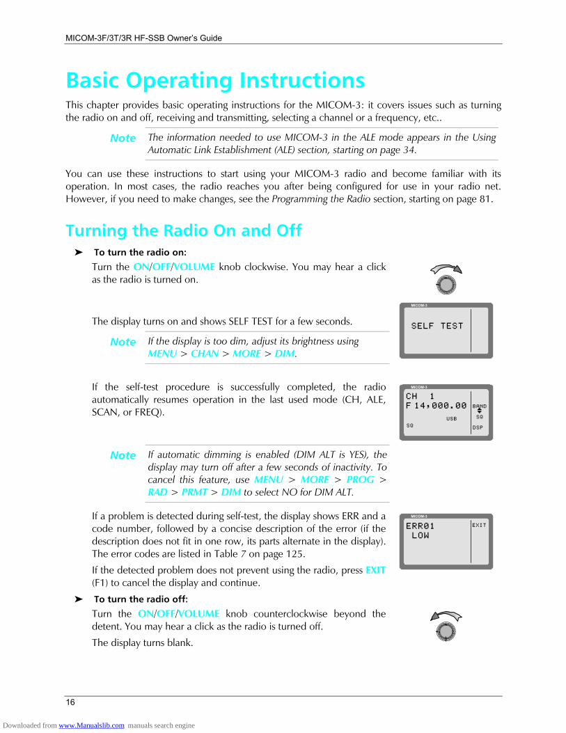
Turning the Radio On and Off To turn the radio on:
Turn the ON/OFF/VOLUME knob clockwise. You may hear a click as the radio is turned on.
The display turns on and shows SELF TEST for a few seconds.
Note If the display is too dim, adjust its brightness using MENU > CHAN > MORE > DIM.
MICOM-3
SELF TEST
If the self-test procedure is successfully completed, the radio automatically resumes operation in the last used mode (CH, ALE, SCAN, or FREQ).
MICOM-3
BAND
SQ
DSP
CH 1F 14,000.00
USBI
SQ
Note If automatic dimming is enabled (DIM ALT is YES), the display may turn off after a few seconds of inactivity. To cancel this feature, use MENU > MORE > PROG > RAD > PRMT > DIM to select NO for DIM ALT.
If a problem is detected during self-test, the display shows ERR and a code number, followed by a concise description of the error (if the description does not fit in one row, its parts alternate in the display). The error codes are listed in Table 7 on page 125.
If the detected problem does not prevent using the radio, press EXIT (F1) to cancel the display and continue.
MICOM-3
EXITERR01 LOW
To turn the radio off:
Turn the ON/OFF/VOLUME knob counterclockwise beyond the detent. You may hear a click as the radio is turned off.
The display turns blank.
Downloaded from www.Manualslib.com manuals search engine
Basic Operating Instructions
17
Transmitting and Receiving Notes • When transmitting, the RF output of the radio must be connected to an
antenna installed as explained in the Installation section page 104 (for maintenance, you may also connect to a dummy load of suitable power rating). Do not attempt to transmit when the antenna is not connected, or when the antenna or any cable leading to it is physically damaged.
• If the antenna system is equipped with an automatic antenna tuner and the tuner is enabled, the radio will automatically tune the antenna tuner. In the Channel mode, pressing the ENTER key automatically retunes the antenna.
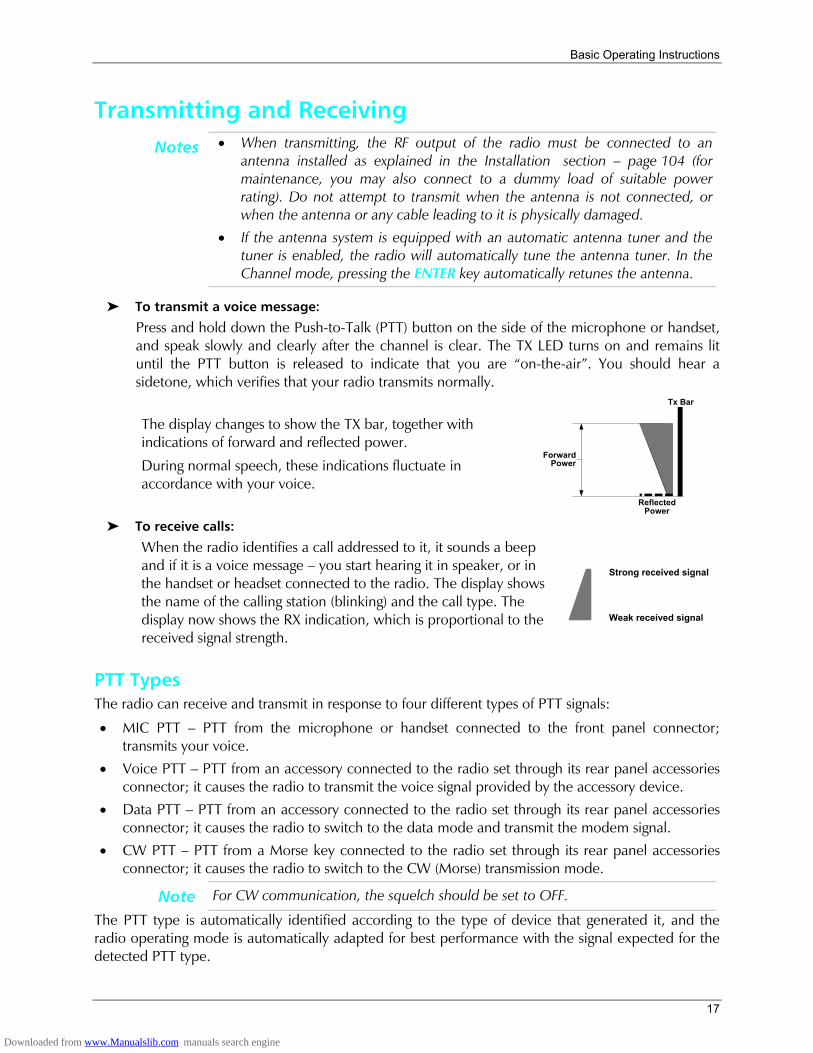
To transmit a voice message:
Press and hold down the Push-to-Talk (PTT) button on the side of the microphone or handset, and speak slowly and clearly after the channel is clear. The TX LED turns on and remains lit until the PTT button is released to indicate that you are on-the-air. You should hear a sidetone, which verifies that your radio transmits normally.
The display changes to show the TX bar, together with indications of forward and reflected power.
During normal speech, these indications fluctuate in accordance with your voice.
ForwardPower
Tx Bar
ReflectedPower
To receive calls:
When the radio identifies a call addressed to it, it sounds a beep and if it is a voice message you start hearing it in speaker, or in the handset or headset connected to the radio. The display shows the name of the calling station (blinking) and the call type. The display now shows the RX indication, which is proportional to the received signal strength.
Strong received signal
Weak received signal
PTT Types The radio can receive and transmit in response to four different types of PTT signals:
• MIC PTT PTT from the microphone or handset connected to the front panel connector; transmits your voice.
• Voice PTT PTT from an accessory connected to the radio set through its rear panel accessories connector; it causes the radio to transmit the voice signal provided by the accessory device.
• Data PTT PTT from an accessory connected to the radio set through its rear panel accessories connector; it causes the radio to switch to the data mode and transmit the modem signal.
• CW PTT PTT from a Morse key connected to the radio set through its rear panel accessories connector; it causes the radio to switch to the CW (Morse) transmission mode.
Note For CW communication, the squelch should be set to OFF.
The PTT type is automatically identified according to the type of device that generated it, and the radio operating mode is automatically adapted for best performance with the signal expected for the detected PTT type.
Downloaded from www.Manualslib.com manuals search engine
MICOM-3F/3T/3R HF-SSB Owners Guide
18
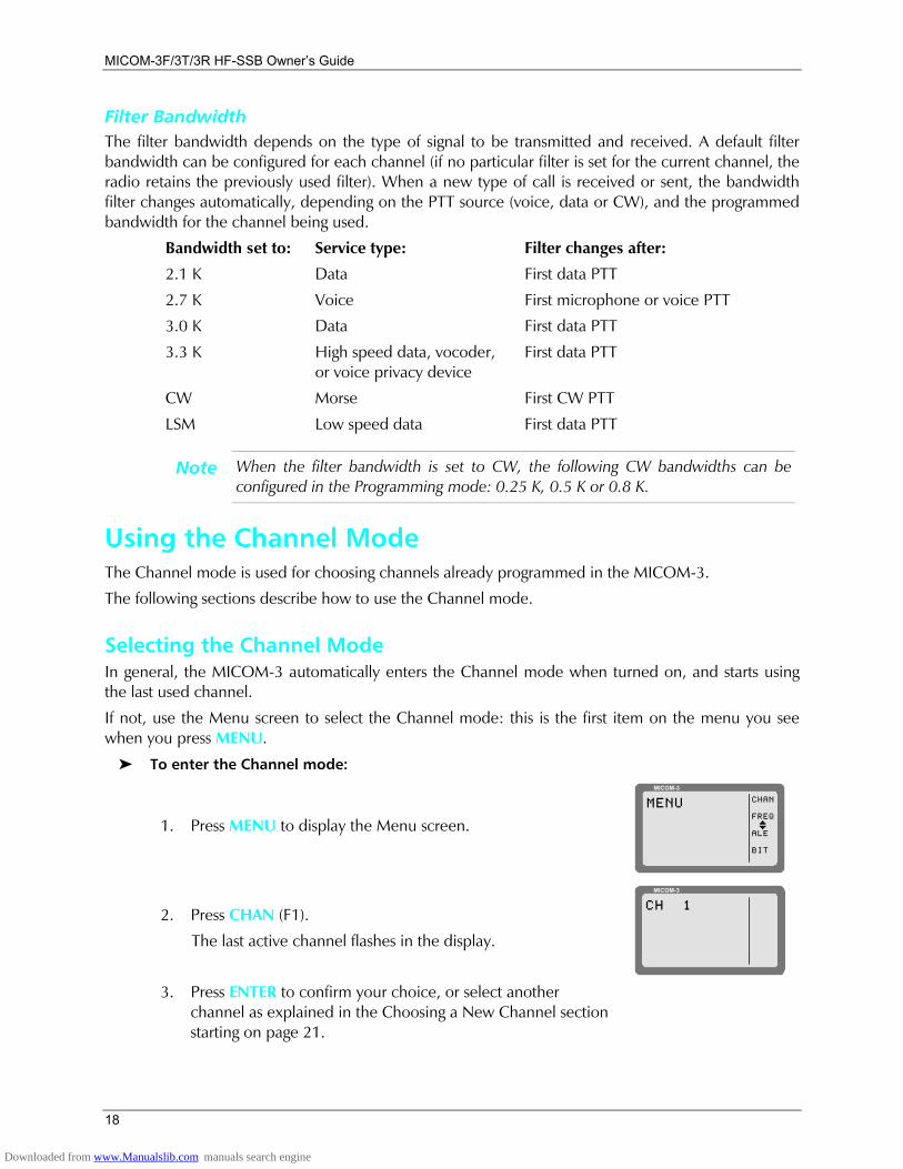
Filter Bandwidth The filter bandwidth depends on the type of signal to be transmitted and received. A default filter bandwidth can be configured for each channel (if no particular filter is set for the current channel, the radio retains the previously used filter). When a new type of call is received or sent, the bandwidth filter changes automatically, depending on the PTT source (voice, data or CW), and the programmed bandwidth for the channel being used.
Bandwidth set to: Service type: Filter changes after:
2.1 K Data First data PTT
2.7 K Voice First microphone or voice PTT
3.0 K Data First data PTT
3.3 K High speed data, vocoder, or voice privacy device
First data PTT
CW Morse First CW PTT
LSM Low speed data First data PTT
Note When the filter bandwidth is set to CW, the following CW bandwidths can be configured in the Programming mode: 0.25 K, 0.5 K or 0.8 K.
Using the Channel Mode The Channel mode is used for choosing channels already programmed in the MICOM-3.
The following sections describe how to use the Channel mode.
Selecting the Channel Mode In general, the MICOM-3 automatically enters the Channel mode when turned on, and starts using the last used channel.
If not, use the Menu screen to select the Channel mode: this is the first item on the menu you see when you press MENU.
To enter the Channel mode:
1. Press MENU to display the Menu screen.
MICOM-3
CHAN
FREQ
ALE
BIT
MENU
I
2. Press CHAN (F1).
The last active channel flashes in the display.
MICOM-3
CH 1
3. Press ENTER to confirm your choice, or select another
channel as explained in the Choosing a New Channel section starting on page 21.
Downloaded from www.Manualslib.com manuals search engine
Basic Operating Instructions
19
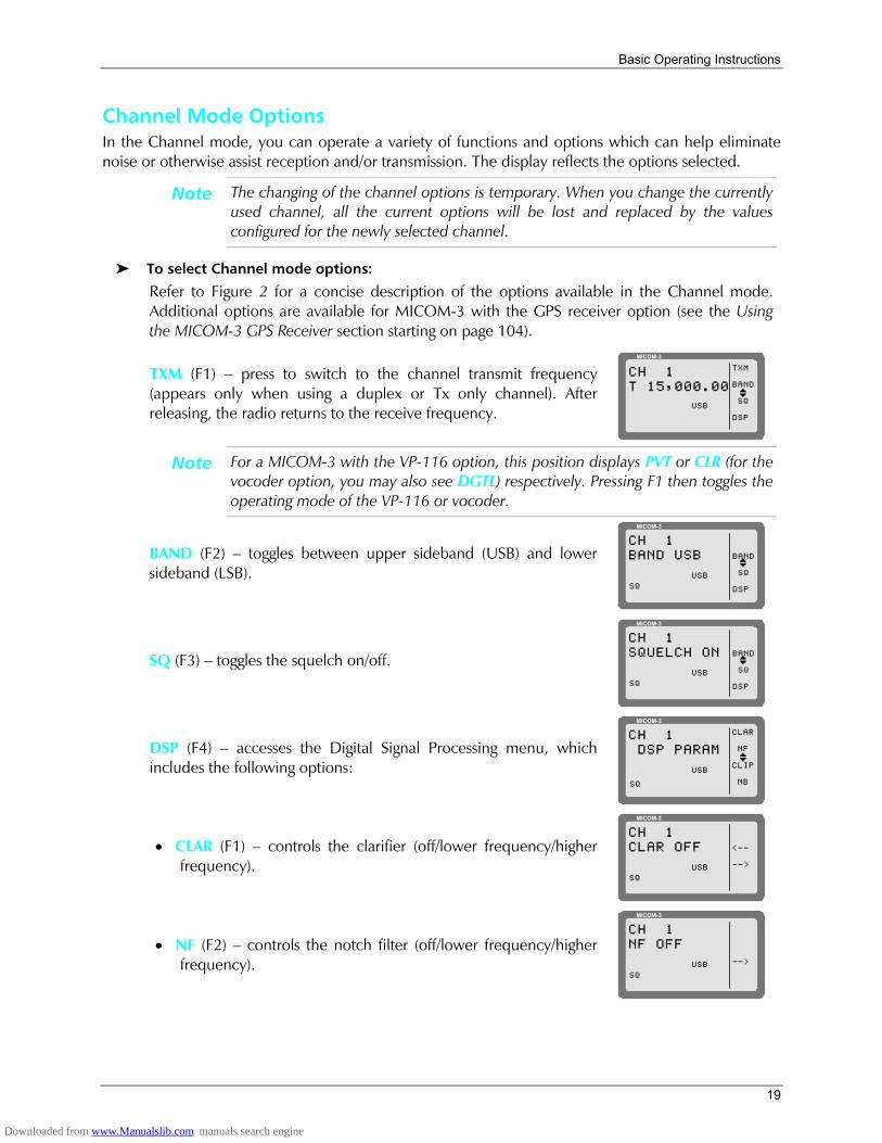
Channel Mode Options In the Channel mode, you can operate a variety of functions and options which can help eliminate noise or otherwise assist reception and/or transmission. The display reflects the options selected.
Note The changing of the channel options is temporary. When you change the currently used channel, all the current options will be lost and replaced by the values configured for the newly selected channel.
To select Channel mode options:
Refer to Figure 2 for a concise description of the options available in the Channel mode. Additional options are available for MICOM-3 with the GPS receiver option (see the Using the MICOM-3 GPS Receiver section starting on page 104).
TXM (F1) press to switch to the channel transmit frequency (appears only when using a duplex or Tx only channel). After releasing, the radio returns to the receive frequency.
MICOM-3
TXM
BAND
SQ
DSP
CH 1T 15,000.00
USBI
Note For a MICOM-3 with the VP-116 option, this position displays PVT or CLR (for the vocoder option, you may also see DGTL) respectively. Pressing F1 then toggles the operating mode of the VP-116 or vocoder.
BAND (F2) toggles between upper sideband (USB) and lower sideband (LSB).
MICOM-3
BAND
SQ
DSP
CH 1BAND USB
USBI
SQ
SQ (F3) toggles the squelch on/off. 13A
MICOM-3
BAND
SQ
DSP
CH 1SQUELCH ON
USBI
SQ
DSP (F4) accesses the Digital Signal Processing menu, which includes the following options:
MICOM-3
CLAR
NF
CLIP
NB
CH 1 DSP PARAM
USBI
SQ
• CLAR (F1) controls the clarifier (off/lower frequency/higher frequency).
13A
MICOM-3
<--
-->
CH 1CLAR OFF
USBSQ
• NF (F2) controls the notch filter (off/lower frequency/higher frequency).
13A
MICOM-3
-->
CH 1NF OFF
USBSQ
Downloaded from www.Manualslib.com manuals search engine
MICOM-3F/3T/3R HF-SSB Owners Guide
20
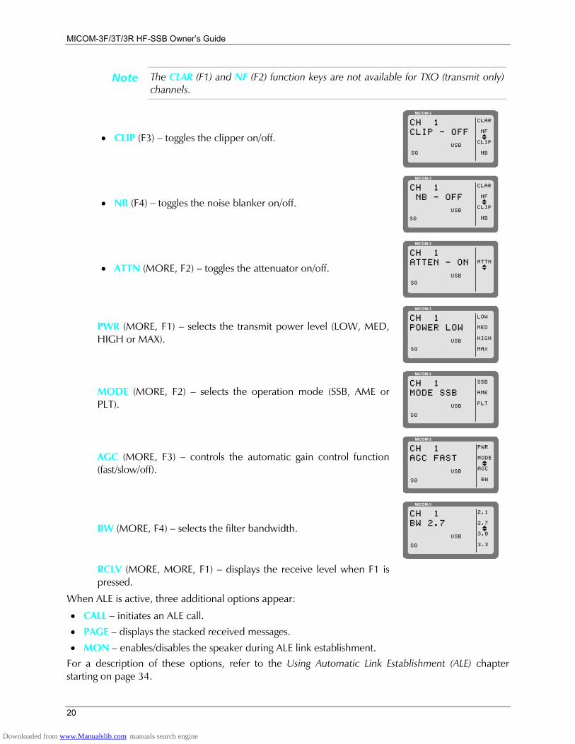
Note The CLAR (F1) and NF (F2) function keys are not available for TXO (transmit only) channels.
• CLIP (F3) toggles the clipper on/off.
MICOM-3
CLAR
NF
CLIP
NB
CH 1CLIP - OFF
USBI
SQ
• NB (F4) toggles the noise blanker on/off.
MICOM-3
CLAR
NF
CLIP
NB
CH 1 NB - OFF
USBI
SQ
• ATTN (MORE, F2) toggles the attenuator on/off.
MICOM-3
ATTNCH 1ATTEN - ON
USBI
SQ
PWR (MORE, F1) selects the transmit power level (LOW, MED, HIGH or MAX).
MICOM-3
LOW
MED
HIGH
MAX
CH 1POWER LOW
USB
SQ
MODE (MORE, F2) selects the operation mode (SSB, AME or PLT).
MICOM-3
SSB
AME
PLT
CH 1MODE SSB
USB
SQ
AGC (MORE, F3) controls the automatic gain control function (fast/slow/off).
MICOM-3
CH 1AGC FAST
USB
SQ
PWR
MODE
AGC
BW
I
BW (MORE, F4) selects the filter bandwidth.
MICOM-3
CH 1BW 2.7
USB
SQ
2.1
2.7
3.0
3.3
I
RCLV (MORE, MORE, F1) displays the receive level when F1 is pressed.
When ALE is active, three additional options appear:
• CALL initiates an ALE call.
• PAGE displays the stacked received messages.
• MON enables/disables the speaker during ALE link establishment. For a description of these options, refer to the Using Automatic Link Establishment (ALE) chapter starting on page 34.
Downloaded from www.Manualslib.com manuals search engine
Basic Operating Instructions
21
MICOM-3
BAND
SQ
DSP
CH 6F 16,000.00
IUSB VP
PVT#CLR
VP-116 only
VCD
PVT#DGTLCLR
Vocoder only
TXMFor duplexand TX onlychannels
BAND DSP PWR
LOWMEDHIGHMAX
CLAR
ONOFF
SQ
ONOFF
MODE AGC
SLOWFASTOFF
More
BW
2.12.73.03.3LSMCW
RCLV
More
CALL
SENDPAGE
More
ALL
NET
GRP
ANY
WILD
SELF
LSBUSB
SSBAMEPLT
ONOFF
ONOFF
-200
OFF
+200
........
........
CLIP
NB
ATTN
....
NF
Only for ALE Enabled
Note 1
MON
ONOFF
SENDCHAN
SENDPAGECHANSEL
SENDPAGECHANSELSENDPAGECHANSEL
SENDPAGECHAN
SENDPAGEGLOBSEL
More
MULT
GPS
Note 2
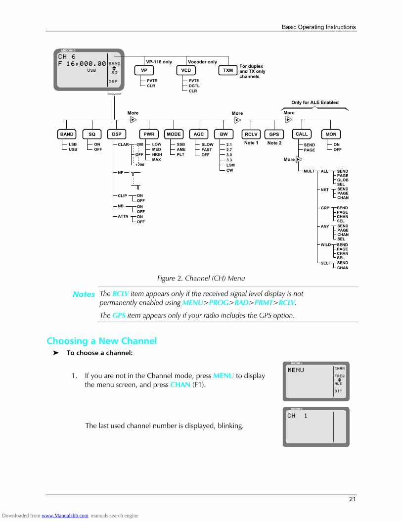
Figure 2. Channel (CH) Menu
Notes The RCLV item appears only if the received signal level display is not permanently enabled using MENU>PROG>RAD>PRMT>RCLV.
The GPS item appears only if your radio includes the GPS option.
Choosing a New Channel To choose a channel:
1. If you are not in the Channel mode, press MENU to display the menu screen, and press CHAN (F1).
MICOM-3
CHAN
FREQ
ALE
BIT
MENU
I
The last used channel number is displayed, blinking.
MICOM-3
CH 1
Downloaded from www.Manualslib.com manuals search engine
MICOM-3F/3T/3R HF-SSB Owners Guide
22
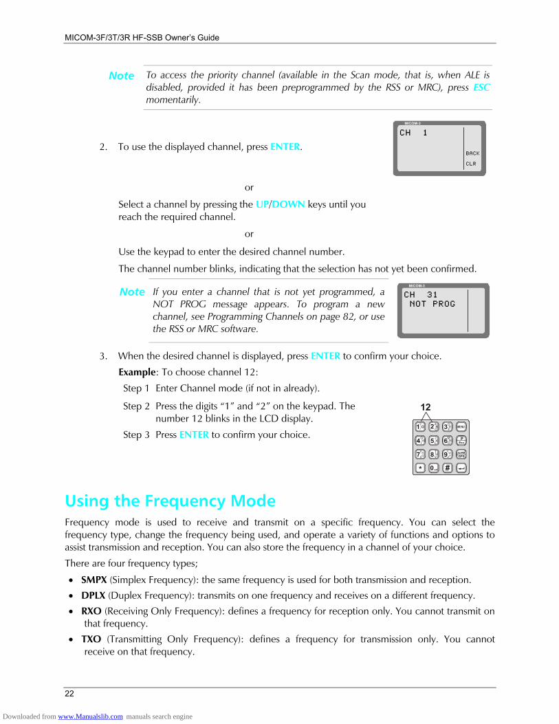
Note To access the priority channel (available in the Scan mode, that is, when ALE is disabled, provided it has been preprogrammed by the RSS or MRC), press ESC momentarily.
2. To use the displayed channel, press ENTER.
MICOM-3
CH 1
BACK
CLR
or
Select a channel by pressing the UP/DOWN keys until you reach the required channel.
or
Use the keypad to enter the desired channel number. The channel number blinks, indicating that the selection has not yet been confirmed.
Note If you enter a channel that is not yet programmed, a NOT PROG message appears. To program a new channel, see Programming Channels on page 82, or use the RSS or MRC software.
MICOM-3
CH 31 NOT PROG
3. When the desired channel is displayed, press ENTER to confirm your choice.
Example: To choose channel 12:
Step 1 Enter Channel mode (if not in already). Step 2 Press the digits 1 and 2 on the keypad. The
number 12 blinks in the LCD display.
Step 3 Press ENTER to confirm your choice. 1?@
/
G
P
H
R
I
S
4
7
*
Q
J MK NL O5 6TUV8 9
A DB EC F2 3
0 #
YWZX
MENU
EscP
GPSALARM
12
Using the Frequency Mode Frequency mode is used to receive and transmit on a specific frequency. You can select the frequency type, change the frequency being used, and operate a variety of functions and options to assist transmission and reception. You can also store the frequency in a channel of your choice.
There are four frequency types;
• SMPX (Simplex Frequency): the same frequency is used for both transmission and reception.
• DPLX (Duplex Frequency): transmits on one frequency and receives on a different frequency.
• RXO (Receiving Only Frequency): defines a frequency for reception only. You cannot transmit on that frequency.
• TXO (Transmitting Only Frequency): defines a frequency for transmission only. You cannot receive on that frequency.
Downloaded from www.Manualslib.com manuals search engine

Basic Operating Instructions
23
The available frequency ranges are:
• Reception: 100 kHz to 30 MHz.
• Transmission: 1.6 to 30 MHz.
Notes • The Frequency mode is accessible only if the radio is not locked.
• ALE and Frequency modes are mutually exclusive.
To enter the frequency mode:
1. Press MENU to display the Menu screen.
MICOM-3
CHAN
FREQ
ALE
BIT
MENU
I
2. Press FREQ (F2). The last used frequency blinks, and the frequency type is displayed in the top line.
MICOM-3
SMPX
DPLX
RXO
TXO
SMPXF 14,000.00
The letter preceding the frequency in the second line of the display indicates whether the frequency is used for Transmission (T), Reception (R) or both transmission and reception (F).
3. To use the displayed frequency and frequency type, press ENTER. If the Frequency type is Duplex, press ENTER twice to accept both transmission and reception frequencies.
or
Change the frequency type and the frequency as explained below.
To change the current frequency/frequencies:
1. If you are not in Frequency mode, press MENU to access the Menu screen, and press FREQ (F2).
MICOM-3
CHAN
FREQ
ALE
BIT
MENU
I
The last used frequency blinks, and the frequency type is displayed in the top line.
MICOM-3
SMPX
DPLX
RXO
TXO
SMPXF 14,000.00
USB
SQ
or
If you are already in the Frequency mode, press MORE until the T/R function appears next to the F1 function key, and then press T/R (F1).
MICOM-3
T/R
BAND
SQ
DSP
FREQF 15,000.00
IUSB
AGC
Downloaded from www.Manualslib.com manuals search engine
MICOM-3F/3T/3R HF-SSB Owners Guide
24
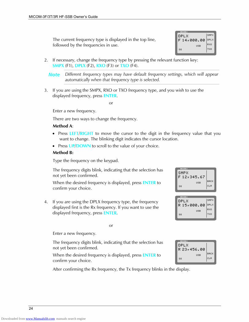
The current frequency type is displayed in the top line, followed by the frequencies in use.
MICOM-3
SMPX
DPLX
RXO
TXO
DPLXF 14,000.00
USB
SQ
2. If necessary, change the frequency type by pressing the relevant function key:
SMPX (F1), DPLX (F2), RXO (F3) or TXO (F4).
Note Different frequency types may have default frequency settings, which will appear automatically when that frequency type is selected.
3. If you are using the SMPX, RXO or TXO frequency type, and you wish to use the displayed frequency, press ENTER.
or Enter a new frequency. There are two ways to change the frequency.
Method A:
• Press LEFT/RIGHT to move the cursor to the digit in the frequency value that you want to change. The blinking digit indicates the cursor location.
• Press UP/DOWN to scroll to the value of your choice. Method B: Type the frequency on the keypad.
The frequency digits blink, indicating that the selection has not yet been confirmed.
When the desired frequency is displayed, press ENTER to confirm your choice.
MICOM-3
BACK
CLR
SMPXF 12,345.67
USB
SQ
4. If you are using the DPLX frequency type, the frequency displayed first is the Rx frequency. If you want to use the displayed frequency, press ENTER.
MICOM-3
SMPX
DPLX
RXO
TXO
DPLXR 15,000.00
USB
SQ
or
Enter a new frequency.
The frequency digits blink, indicating that the selection has not yet been confirmed.
When the desired frequency is displayed, press ENTER to confirm your choice.
MICOM-3
BACK
CLR
DPLXR 23,456.00
USB
SQ
After confirming the Rx frequency, the Tx frequency blinks in the display.
Downloaded from www.Manualslib.com manuals search engine
Basic Operating Instructions
25
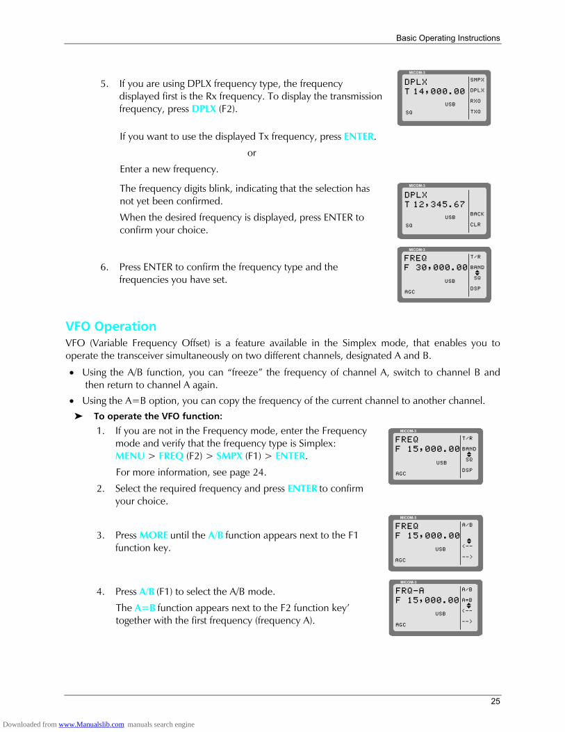
5. If you are using DPLX frequency type, the frequency displayed first is the Rx frequency. To display the transmission frequency, press DPLX (F2).
MICOM-3
SMPX
DPLX
RXO
TXO
DPLXT 14,000.00
USB
SQ
If you want to use the displayed Tx frequency, press ENTER.
or
Enter a new frequency.
The frequency digits blink, indicating that the selection has not yet been confirmed.
When the desired frequency is displayed, press ENTER to confirm your choice.
MICOM-3
BACK
CLR
DPLXT 12,345.67
USB
SQ
6. Press ENTER to confirm the frequency type and the frequencies you have set.
MICOM-3
T/R
BAND
SQ
DSP
FREQF 30,000.00
IUSB
AGC
VFO Operation VFO (Variable Frequency Offset) is a feature available in the Simplex mode, that enables you to operate the transceiver simultaneously on two different channels, designated A and B.
• Using the A/B function, you can freeze the frequency of channel A, switch to channel B and then return to channel A again.
• Using the A=B option, you can copy the frequency of the current channel to another channel. To operate the VFO function:
1. If you are not in the Frequency mode, enter the Frequency mode and verify that the frequency type is Simplex: MENU > FREQ (F2) > SMPX (F1) > ENTER.
For more information, see page 24.
2. Select the required frequency and press ENTER to confirm your choice.
MICOM-3
T/R
BAND
SQ
DSP
FREQF 15,000.00
IUSB
AGC
3. Press MORE until the A/B function appears next to the F1 function key.
MICOM-3
A/B
<--
-->
FREQF 15,000.00
IUSB
AGC
4. Press A/B (F1) to select the A/B mode.
The A=B function appears next to the F2 function key together with the first frequency (frequency A).
MICOM-3
A/B
A=B
<--
-->
FRQ-AF 15,000.00
IUSB
AGC
Downloaded from www.Manualslib.com manuals search engine
MICOM-3F/3T/3R HF-SSB Owners Guide
26
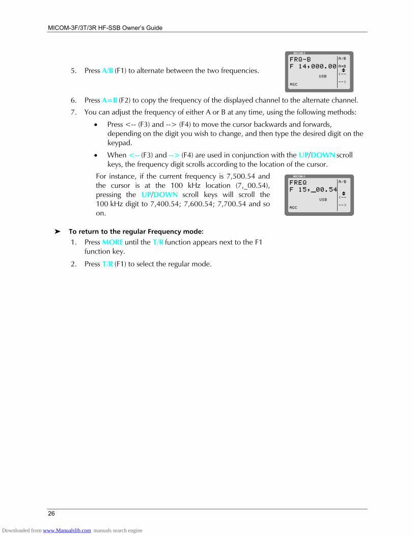
5. Press A/B (F1) to alternate between the two frequencies.
MICOM-3
A/B
A=B
<--
-->
FRQ-BF 14,000.00
IUSB
AGC
6. Press A=B (F2) to copy the frequency of the displayed channel to the alternate channel.
7. You can adjust the frequency of either A or B at any time, using the following methods:
• Press <-- (F3) and --> (F4) to move the cursor backwards and forwards, depending on the digit you wish to change, and then type the desired digit on the keypad.
• When <-- (F3) and --> (F4) are used in conjunction with the UP/DOWN scroll keys, the frequency digit scrolls according to the location of the cursor.
For instance, if the current frequency is 7,500.54 and the cursor is at the 100 kHz location (7,_00.54), pressing the UP/DOWN scroll keys will scroll the 100 kHz digit to 7,400.54; 7,600.54; 7,700.54 and so on.
MICOM-3
A/B
<--
-->
FREQF 15,_00.54
IUSB
AGC
To return to the regular Frequency mode:
1. Press MORE until the T/R function appears next to the F1 function key.
2. Press T/R (F1) to select the regular mode.
Downloaded from www.Manualslib.com manuals search engine
Basic Operating Instructions
27
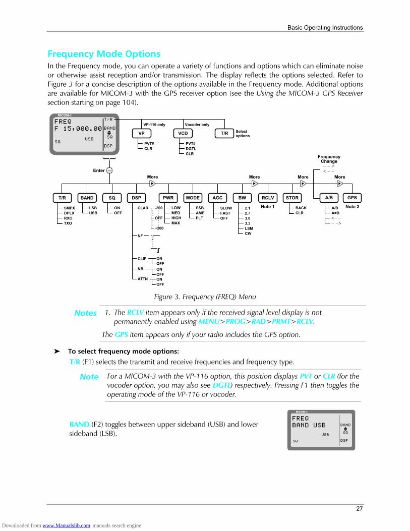
Frequency Mode Options In the Frequency mode, you can operate a variety of functions and options which can eliminate noise or otherwise assist reception and/or transmission. The display reflects the options selected. Refer to Figure 3 for a concise description of the options available in the Frequency mode. Additional options are available for MICOM-3 with the GPS receiver option (see the Using the MICOM-3 GPS Receiver section starting on page 104).
MICOM-3T/R
BAND
SQ
DSP
FREQF 15,000.00
IUSB
SQ
Enter
BAND DSP PWR
CLAR
ONOFF
SQ
ONOFF
MODE AGC
SLOWFASTOFF
More
BW
2.12.73.03.3LSMCW
RCLV
More
STOR
BACKCLR
More
LSBUSB
SSBAMEPLT
ONOFF
ONOFF
-200
OFF
+200
........
........
CLIP
NB
ATTN
....
NF
Note 1
T/R A/B
A/BA=B<− −− −>
LOWMEDHIGHMAX
SMPXDPLXRXOTXO
VP
PVT#CLR
VP-116 only
VCD
PVT#DGTLCLR
Vocoder only
T/R Selectoptions
GPS
More
FrequencyChange− − >< − −
Note 2
Figure 3. Frequency (FREQ) Menu
Notes 1. The RCLV item appears only if the received signal level display is not permanently enabled using MENU>PROG>RAD>PRMT>RCLV.
The GPS item appears only if your radio includes the GPS option.
To select frequency mode options:
T/R (F1) selects the transmit and receive frequencies and frequency type.
Note For a MICOM-3 with the VP-116 option, this position displays PVT or CLR (for the vocoder option, you may also see DGTL) respectively. Pressing F1 then toggles the operating mode of the VP-116 or vocoder.
BAND (F2) toggles between upper sideband (USB) and lower sideband (LSB).
MICOM-3
FREQBAND USB
USB
SQ
BAND
SQ
DSP
I
Downloaded from www.Manualslib.com manuals search engine
MICOM-3F/3T/3R HF-SSB Owners Guide
28
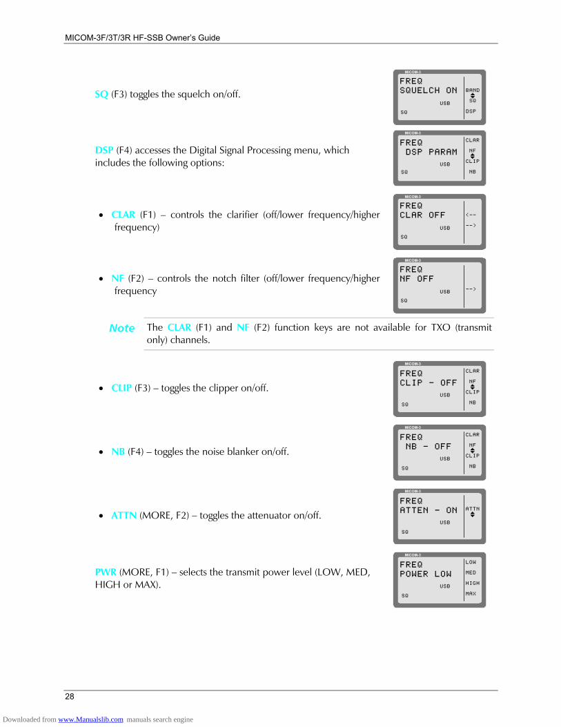
SQ (F3) toggles the squelch on/off.
MICOM-3
FREQSQUELCH ON
USB
SQ
BAND
SQ
DSP
I
DSP (F4) accesses the Digital Signal Processing menu, which includes the following options:
MICOM-3
FREQ DSP PARAM
USB
CLAR
NF
CLIP
NB
I
SQ
• CLAR (F1) controls the clarifier (off/lower frequency/higher frequency)
MICOM-3
FREQCLAR OFF
USB
SQ
<--
-->
• NF (F2) controls the notch filter (off/lower frequency/higher frequency
MICOM-3
FREQNF OFF
USB
SQ
-->
Note The CLAR (F1) and NF (F2) function keys are not available for TXO (transmit only) channels.
• CLIP (F3) toggles the clipper on/off.
MICOM-3
FREQCLIP - OFF
USB
CLAR
NF
CLIP
NB
I
SQ
• NB (F4) toggles the noise blanker on/off.
MICOM-3
FREQ NB - OFF
USB
CLAR
NF
CLIP
NB
I
SQ
• ATTN (MORE, F2) toggles the attenuator on/off.
MICOM-3
FREQATTEN - ON
USB
ATTNI
SQ
PWR (MORE, F1) selects the transmit power level (LOW, MED, HIGH or MAX).
MICOM-3
FREQPOWER LOW
USB
LOW
MED
HIGH
MAXSQ
Downloaded from www.Manualslib.com manuals search engine

Basic Operating Instructions
29
MODE (MORE, F2) selects the operation mode (SSB, AME or PLT).
MICOM-3
FREQMODE SSB
USB
SSB
AME
PLT
SQ
AGC (MORE, F3) controls the automatic gain control (fast/slow/off).
MICOM-3
FREQAGC FAST
USB
PWR
MODE
AGC
BW
I
SQ
BW (MORE, F4) selects the filter bandwidth.
MICOM-3
FREQBW 2.7
USB
2.1
2.7
3.0
3.3
I
SQ
RCLV (MORE, MORE, F1) displays the receive level when F1 is pressed.
STOR (MORE, MORE, F2) stores the frequency parameters in the selected channel.
<-- (MORE, MORE, F3) and --> (MORE, MORE, F4) move the cursor backwards and forwards. When these function keys are used in conjunction with the UP/DOWN scroll keys, the frequency scrolls according to the location of the cursor, enabling you to change the frequency with greater ease.
Storing Frequencies You can store specific frequencies and frequency parameters in channels which you have programmed (see Programming Channels on page 82).
To store a frequency in a channel:
1. If you are not in the Frequency mode, press MENU to display the Menu screen.
MICOM-3
CHAN
FREQ
ALE
BIT
MENU
I
2. Press FREQ (F2).
The last used frequency blinks, and the frequency type is displayed in the top line.
3. If you wish to use the displayed frequency and frequency type, press ENTER. If the frequency type is DPLX, press ENTER twice to accept both transmission and reception frequencies.
or
Change the frequency type and the frequency as required (see To change the current frequency/frequencies on page 23).
4. If necessary, select the other parameters, using the MORE key and pressing the required function keys (see To select frequency mode options on page 27).
5. Press MORE twice, and then press STOR (F2).
Downloaded from www.Manualslib.com manuals search engine
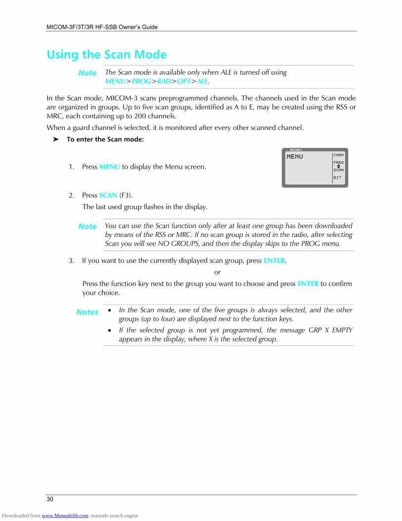
MICOM-3F/3T/3R HF-SSB Owners Guide
30
Using the Scan Mode Note The Scan mode is available only when ALE is turned off using
MENU>PROG>RAD>OPT>ALE.
In the Scan mode, MICOM-3 scans preprogrammed channels. The channels used in the Scan mode are organized in groups. Up to five scan groups, identified as A to E, may be created using the RSS or MRC, each containing up to 200 channels.
When a guard channel is selected, it is monitored after every other scanned channel.
To enter the Scan mode:
1. Press MENU to display the Menu screen.
MICOM-3
CHAN
FREQ
SCAN
BIT
MENU
I
2. Press SCAN (F3).
The last used group flashes in the display.
Note You can use the Scan function only after at least one group has been downloaded by means of the RSS or MRC. If no scan group is stored in the radio, after selecting Scan you will see NO GROUPS, and then the display skips to the PROG menu.
3. If you want to use the currently displayed scan group, press ENTER.
or
Press the function key next to the group you want to choose and press ENTER to confirm your choice.
Notes • In the Scan mode, one of the five groups is always selected, and the other groups (up to four) are displayed next to the function keys.
• If the selected group is not yet programmed, the message GRP X EMPTY appears in the display, where X is the selected group.
Downloaded from www.Manualslib.com manuals search engine
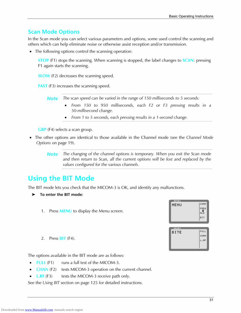
Basic Operating Instructions
31
Scan Mode Options In the Scan mode you can select various parameters and options, some used control the scanning and others which can help eliminate noise or otherwise assist reception and/or transmission.
• The following options control the scanning operation:
STOP (F1) stops the scanning. When scanning is stopped, the label changes to SCAN: pressing F1 again starts the scanning.
SLOW (F2) decreases the scanning speed.
FAST (F3) increases the scanning speed.
Note The scan speed can be varied in the range of 150 milliseconds to 5 seconds:
• From 150 to 950 milliseconds, each F2 or F3 pressing results in a 50-millisecond change.
• From 1 to 5 seconds, each pressing results in a 1-second change.
GRP (F4) selects a scan group.
• The other options are identical to those available in the Channel mode (see the Channel Mode Options on page 19).
Note The changing of the channel options is temporary. When you exit the Scan mode and then return to Scan, all the current options will be lost and replaced by the values configured for the various channels.
Using the BIT Mode The BIT mode lets you check that the MICOM-3 is OK, and identify any malfunctions.
To enter the BIT mode:
1. Press MENU to display the Menu screen.
MICOM-3
CHAN
FREQ
ALE
BIT
MENU
I
2. Press BIT (F4).
MICOM-3
FULL
CHAN
L.RF
BITE
The options available in the BIT mode are as follows:
• FULL (F1) runs a full test of the MICOM-3.
• CHAN (F2) tests MICOM-3 operation on the current channel.
• L.RF (F3) tests the MICOM-3 receive path only. See the Using BIT section on page 125 for detailed instructions.
Downloaded from www.Manualslib.com manuals search engine
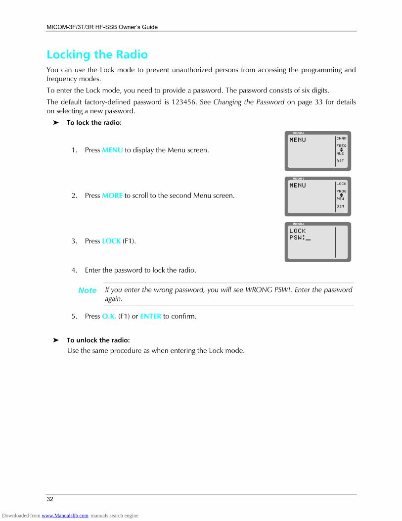
MICOM-3F/3T/3R HF-SSB Owners Guide
32
Locking the Radio You can use the Lock mode to prevent unauthorized persons from accessing the programming and frequency modes.
To enter the Lock mode, you need to provide a password. The password consists of six digits.
The default factory-defined password is 123456. See Changing the Password on page 33 for details on selecting a new password.
To lock the radio:
1. Press MENU to display the Menu screen.
MICOM-3
CHAN
FREQ
ALE
BIT
MENU
I
2. Press MORE to scroll to the second Menu screen.
MICOM-3
LOCK
PROG
PSW
DIM
MENU
I
3. Press LOCK (F1).
MICOM-3
LOCKPSW:_
4. Enter the password to lock the radio.
Note If you enter the wrong password, you will see WRONG PSW!. Enter the password again.
5. Press O.K. (F1) or ENTER to confirm.
To unlock the radio:
Use the same procedure as when entering the Lock mode.
Downloaded from www.Manualslib.com manuals search engine
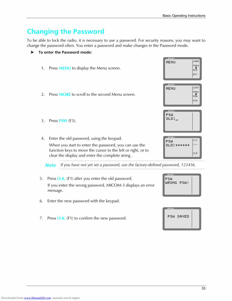
Basic Operating Instructions
33
Changing the Password To be able to lock the radio, it is necessary to use a password. For security reasons, you may want to change the password often. You enter a password and make changes in the Password mode.
To enter the Password mode:
1. Press MENU to display the Menu screen.
MICOM-3
CHAN
FREQ
ALE
BIT
MENU
I
2. Press MORE to scroll to the second Menu screen.
MICOM-3
LOCK
PROG
PSW
DIM
MENU
I
3. Press PSW (F3).
MICOM-3
PSWOLD:_
4. Enter the old password, using the keypad.
When you start to enter the password, you can use the function keys to move the cursor to the left or right, or to clear the display and enter the complete string .
MICOM-3
O.K
<--
CLR
PSWOLD:******
Note If you have not yet set a password, use the factory-defined password, 123456.
5. Press O.K. (F1) after you enter the old password.
If you enter the wrong password, MICOM-3 displays an error message.
MICOM-3
PSWWRONG PSW!
6. Enter the new password with the keypad.
7. Press O.K. (F1) to confirm the new password.
MICOM-3
PSW SAVED
Downloaded from www.Manualslib.com manuals search engine
MICOM-3F/3T/3R HF-SSB Owners Guide
34
Using Automatic Link Establishment (ALE) The MICOM-3 unit supports the Automatic Link Establishment (ALE) function, a method that enables automatically selecting the best working channel from a group of preprogrammed channels without any user intervention, thereby facilitating communication among HF radio stations and improving the communications quality and reliability. The ALE incorporates all the advanced data transmission techniques required by MIL-STD-188-141B and FED-STD-1045.
The ALE function ensures the best possible link without requiring prior knowledge of radio communication conditions, and thus enables reliable HF communication even under rapidly changing propagation conditions. For this purpose, HF radio sets using the ALE function continuously monitor and evaluate the transmission quality on each frequency assigned for communication, and automatically select an optimal frequency for each transmission. After selecting the optimal frequency, a link between the communicating stations is established via an automatic handshake process, which is performed without requiring operators intervention.
ALE combines sounding, scanning, selective calling, channel selection and LQA (Link Quality Analysis). These features, all automatic, ensure that communication takes place on the channel with the best link quality, even with an unskilled operator. The ALE also includes many types of calls you can use to rapidly and efficiently set up links with other ALE users, and features such as messages, stack and quick call.
The following sections present an overview of MICOM-3 ALE capabilities and services, and then provide instructions on using ALE.
ALE Capabilities and Features Scanning The method used to select the best channel is based on scanning: as long as it is idle, a radio operating in the ALE mode switches frequency at a relatively rapid rate (programmable at 2 or 5 channels per second) within the group of channels that can be used (the ALE frequency table, with up to 100 frequencies). During this process, it collects information regarding the state of each channel (busy/free and its background noise) that can be used together with the quality information collected by sounding when the user initiates a call.
• When a station initiates a call, it selects the best free channel on the basis of the most recent information, switches to that channel and then transmits a call request for a time sufficient for any station to finish scanning all the preprogrammed channels and reach the selected channel.
• Any station that should receive this call will then stop on the channel used by the initiating station, and will use the channel for communication. The exact response to the call request depends on the type of call (call types are described below): as a result, it is possible to program any desired station to ignore some types of calls (in fact, any call not specifically addressed to it).
Sounding Automatic sounding is the method used by ALE for testing the quality of channels and propagation paths under field conditions. The sounding signal is a unilateral identifying broadcast, repeated at periodic intervals on unoccupied channels.
Downloaded from www.Manualslib.com manuals search engine
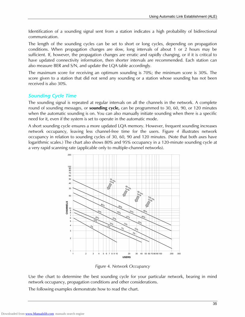
Using Automatic Link Establishment (ALE)
35
Identification of a sounding signal sent from a station indicates a high probability of bidirectional communication.
The length of the sounding cycles can be set to short or long cycles, depending on propagation conditions. When propagation changes are slow, long intervals of about 1 or 2 hours may be sufficient. If, however, the propagation changes are erratic and rapidly changing, or if it is critical to have updated connectivity information, then shorter intervals are recommended. Each station can also measure BER and S/N, and update the LQA table accordingly.
The maximum score for receiving an optimum sounding is 70%; the minimum score is 30%. The score given to a station that did not send any sounding or a station whose sounding has not been received is also 30%.
Sounding Cycle Time The sounding signal is repeated at regular intervals on all the channels in the network. A complete round of sounding messages, or sounding cycle, can be programmed to 30, 60, 90, or 120 minutes when the automatic sounding is on. You can also manually initiate sounding when there is a specific need for it, even if the system is set to operate in the automatic mode.
A short sounding cycle ensures a more updated LQA memory. However, frequent sounding increases network occupancy, leaving less channel-free time for the users. Figure 4 illustrates network occupancy in relation to sounding cycles of 30, 60, 90 and 120 minutes. (Note that both axes have logarithmic scales.) The chart also shows 80% and 95% occupancy in a 120-minute sounding cycle at a very rapid scanning rate (applicable only to multiple-channel networks).
80%1098
3
765
4
2
1
200
1009080706050
40
30
50
1 2 3 4 5 6 7 8 9 10 20 30 40 50 60 70 80 90 300200100
USERS
CH
AN
NEL
S
53%
40%
80%
20%
27%
40%
80%
40%
20%
13%
10%
20%
10%
7%
5%
5%
10%
5%
60 mincycle
30 mincycle
90 mincycle120 mincycle
Figure 4. Network Occupancy
Use the chart to determine the best sounding cycle for your particular network, bearing in mind network occupancy, propagation conditions and other considerations.
The following examples demonstrate how to read the chart.
Downloaded from www.Manualslib.com manuals search engine
MICOM-3F/3T/3R HF-SSB Owners Guide
36
• In a network of nine channels used by eight members, a 30-minute sounding cycle would result in 80% occupancy; a 60-minute cycle would result in 40% occupancy; a 90-minute cycle would result in 27% occupancy and a 120-minute cycle would result in 20% occupancy.
• If there are only two or three channels in the network, a sounding cycle of 30 minutes allows enough channel-free time, even for as many as ten users.
Under field conditions, occupancy will usually be less than the value obtained from the chart because not every station receives all the soundings that are being broadcast on all channels.
To increase channel-free time for the users by reducing network occupancy, you can try one of these four methods (in this order):
1. Increase the sounding cycle time (to 90 or 120 minutes).
2. Reduce the number of channels in the network (for example, by using different nets for different times of day).
3. Reduce the number of stations in the network by re-arranging the hierarchical subgrouping of stations.
4. Request all stations to set the fast scan rate option.
Manual Sounding When it is necessary to perform a rapid sounding cycle on all channels instead of, or in addition to the automatic sounding cycle, manual sounding can be used.
LQA Memory The ALE builds a database of connectivity information based on calls and the ALE sounding messages transmitted by other stations in the network. This information is stored in a special LQA memory and is used to determine the link quality of all channels in the networks. The data in the LQA memory is time-weighted, that is, recent information is given more value than old, thus compensating for changing propagation conditions.
Bidirectional Handshake The bidirectional handshake is an operator-initiated procedure used to exchange LQA scores with other stations without establishing a link.
Note The MICOM-3 can also be programmed to automatically initiate the call to the station after finishing the bidirectional handshake (using the BDLK parameter reached under the ALE programming options).
This procedure is useful in the following cases:
• The radio has only recently been switched on and the automatic sounding cycle has not yet been completed.
• The operator wishes to update the LQA scores before initiating a call to another station, for example, for example, because of abrupt atmospheric charges, or other propagation changes.
• A new or passive station has joined the system. A bidirectional handshake can be carried out with a single station or with all stations in the net. It can be carried out either on a single channel, or on all the net channels. When required, a message can also be added to the procedure.
Downloaded from www.Manualslib.com manuals search engine
Using Automatic Link Establishment (ALE)
37
After a bidirectional handshake with a single station, the LQA matrices of both radios are updated. The operator can then initiate a call to that station and obtain the best channel automatically.
When the bidirectional handshake procedure is performed with a net, all the stations in the net update their LQA tables.
Selective Calling MICOM-3 uses an approach standardized in MIL-STD-181-141B and FED-1075 to selective calling, and therefore has the capability and flexibility to link with one or many prearranged or as-needed single or multiple stations.
ALE Addressing Method ALE uses digital addresses to identify stations. The fundamental address element in the ALE system is the single word: one ALE address word must always contain three characters (one triplet).
A single ALE word is needed for the basic individual station address (this is called a basic address). To increase the available range of addresses, basic addresses can be expanded up to a maximum of 5 words (15 characters): such addresses are called extended addresses.
The characters that can used in addresses are a subset of the standard Basic 38 ASCII character set. This subset includes:
• All the capital (upper case) letters (A to Z)
• All the digits (0 to 9)
• Two utility characters:
!"The stuffing symbol @. It can be used to add characters at the end of an address, so that the resulting length is a whole number of words (triplets). A receiving station then interprets only the non-stuffing characters. For example, if the address has 8 characters, add one @ at the end of the address, whereas for an address with 7 characters, two @ symbols must be added. In special addressing modes, this symbol is interpreted as an ignore instruction: see additional utilization guidelines in Table 1.
!"The wildcard symbol ?. It is used to indicate that any character (except @) is acceptable (this is the equivalent of a dont mind instruction). See Table 2 for utilization guidelines in the special addressing modes.
Note In the following sections, A, B, C or D indicates any alphanumeric character other than @ or ?.
MICOM-3 has the capacity to store and use 100 addresses of up to 15 characters each. MICOM-3 will reject addresses longer than 15 characters, and will notify you with an UFA WRONG message.
Address and Call Types ALE stations, including the MICOM-3, have the capability and flexibility to link with one or many prearranged or as-needed single or multiple stations. There are three general addressing methods:
• Individual station addressing
• Multiple stations addressing, for example, net and group
• Special addressing modes, for example, AllCall, AnyCall, etc. The following sections explain the addressing modes and how they can be used for various purposes.
Downloaded from www.Manualslib.com manuals search engine
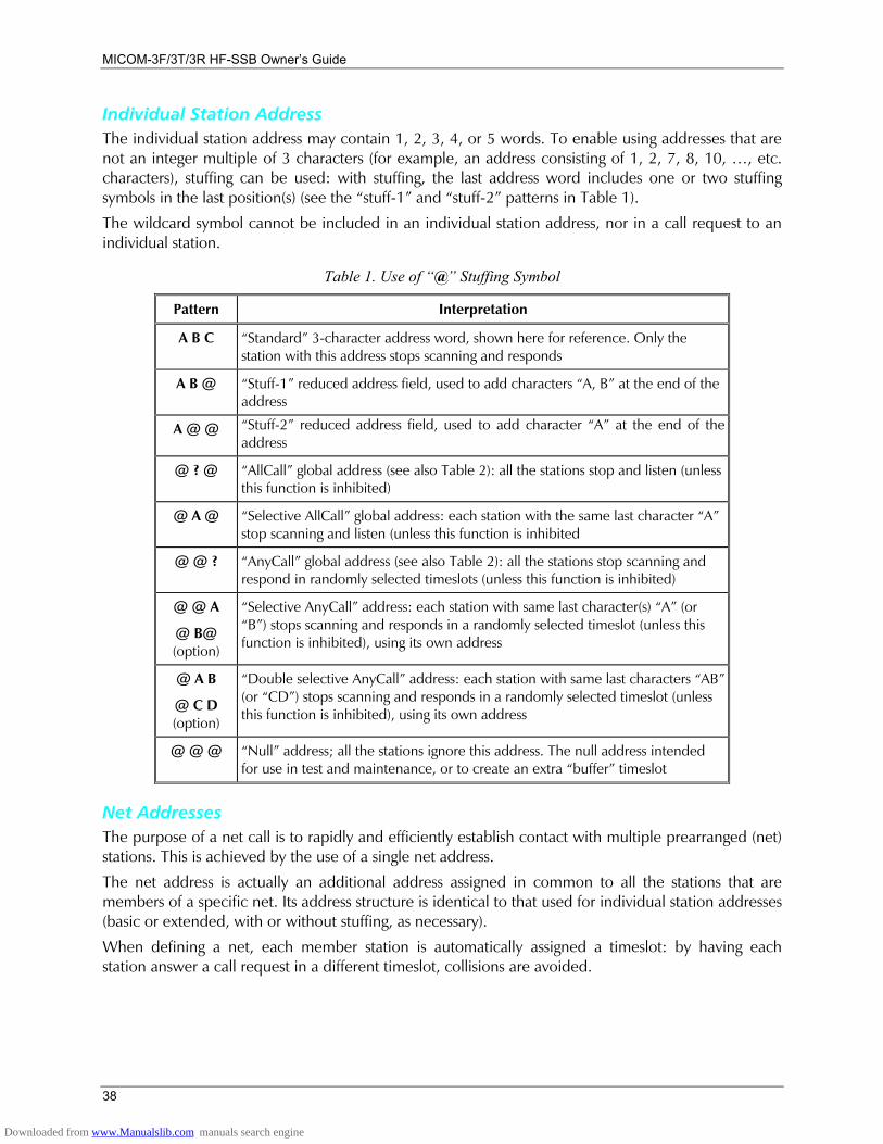
MICOM-3F/3T/3R HF-SSB Owners Guide
38
Individual Station Address The individual station address may contain 1, 2, 3, 4, or 5 words. To enable using addresses that are not an integer multiple of 3 characters (for example, an address consisting of 1, 2, 7, 8, 10, , etc. characters), stuffing can be used: with stuffing, the last address word includes one or two stuffing symbols in the last position(s) (see the stuff-1 and stuff-2 patterns in Table 1).
The wildcard symbol cannot be included in an individual station address, nor in a call request to an individual station.
Table 1. Use of @ Stuffing Symbol
Pattern Interpretation
A B C Standard 3-character address word, shown here for reference. Only the station with this address stops scanning and responds
A B @ Stuff-1 reduced address field, used to add characters A, B at the end of the address
A @ @ Stuff-2 reduced address field, used to add character A at the end of the address
@ ? @ AllCall global address (see also Table 2): all the stations stop and listen (unless this function is inhibited)
@ A @ Selective AllCall global address: each station with the same last character A stop scanning and listen (unless this function is inhibited
@ @ ? AnyCall global address (see also Table 2): all the stations stop scanning and respond in randomly selected timeslots (unless this function is inhibited)
@ @ A
@ B@ (option)
Selective AnyCall address: each station with same last character(s) A (or B) stops scanning and responds in a randomly selected timeslot (unless this function is inhibited), using its own address
@ A B
@ C D (option)
Double selective AnyCall address: each station with same last characters AB (or CD) stops scanning and responds in a randomly selected timeslot (unless this function is inhibited), using its own address
@ @ @ Null address; all the stations ignore this address. The null address intended for use in test and maintenance, or to create an extra buffer timeslot
Net Addresses The purpose of a net call is to rapidly and efficiently establish contact with multiple prearranged (net) stations. This is achieved by the use of a single net address.
The net address is actually an additional address assigned in common to all the stations that are members of a specific net. Its address structure is identical to that used for individual station addresses (basic or extended, with or without stuffing, as necessary).
When defining a net, each member station is automatically assigned a timeslot: by having each station answer a call request in a different timeslot, collisions are avoided.
Downloaded from www.Manualslib.com manuals search engine
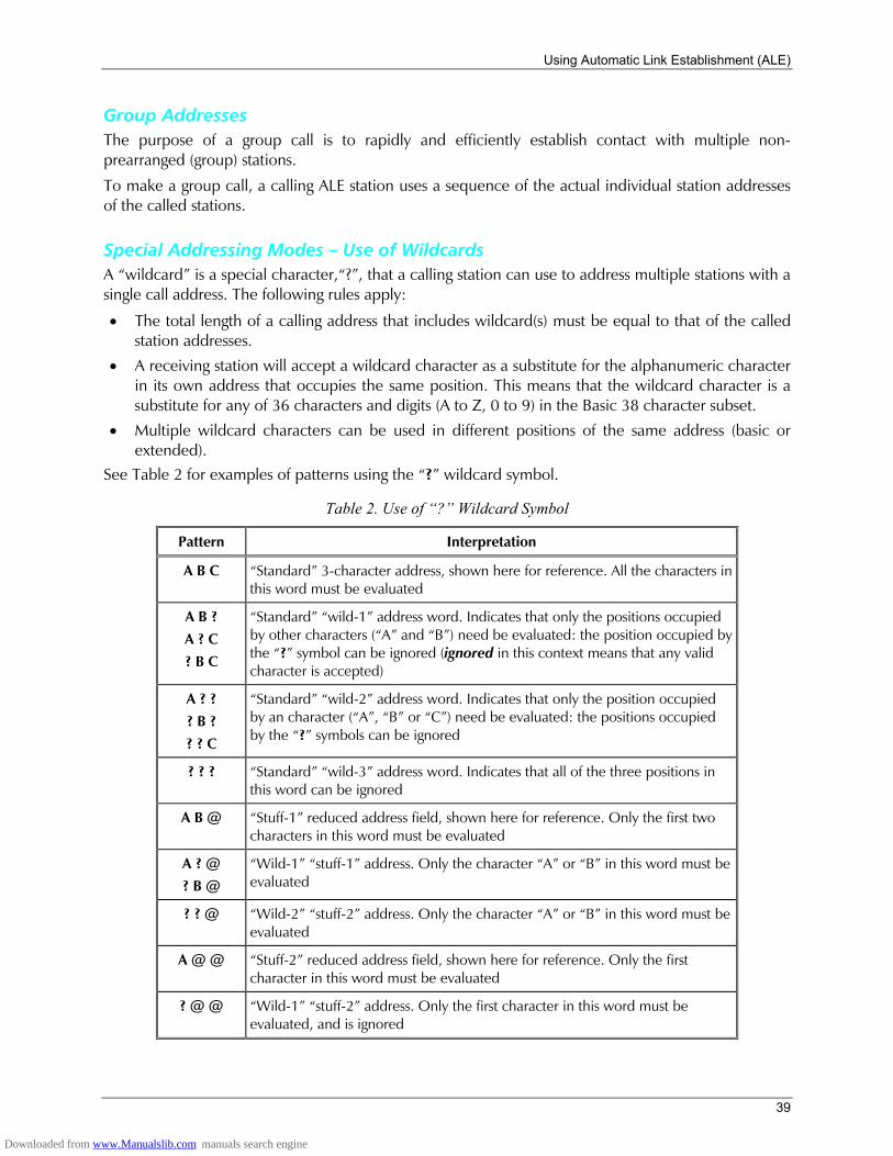
Using Automatic Link Establishment (ALE)
39
Group Addresses The purpose of a group call is to rapidly and efficiently establish contact with multiple non-prearranged (group) stations.
To make a group call, a calling ALE station uses a sequence of the actual individual station addresses of the called stations.
Special Addressing Modes Use of Wildcards A wildcard is a special character,?, that a calling station can use to address multiple stations with a single call address. The following rules apply:
• The total length of a calling address that includes wildcard(s) must be equal to that of the called station addresses.
• A receiving station will accept a wildcard character as a substitute for the alphanumeric character in its own address that occupies the same position. This means that the wildcard character is a substitute for any of 36 characters and digits (A to Z, 0 to 9) in the Basic 38 character subset.
• Multiple wildcard characters can be used in different positions of the same address (basic or extended).
See Table 2 for examples of patterns using the ? wildcard symbol.
Table 2. Use of ? Wildcard Symbol
Pattern Interpretation
A B C Standard 3-character address, shown here for reference. All the characters in this word must be evaluated
A B ? A ? C ? B C
Standard wild-1 address word. Indicates that only the positions occupied by other characters (A and B) need be evaluated: the position occupied by the ? symbol can be ignored (ignored in this context means that any valid character is accepted)
A ? ? ? B ? ? ? C
Standard wild-2 address word. Indicates that only the position occupied by an character (A, B or C) need be evaluated: the positions occupied by the ? symbols can be ignored
? ? ? Standard wild-3 address word. Indicates that all of the three positions in this word can be ignored
A B @ Stuff-1 reduced address field, shown here for reference. Only the first two characters in this word must be evaluated
A ? @ ? B @
Wild-1 stuff-1 address. Only the character A or B in this word must be evaluated
? ? @ Wild-2 stuff-2 address. Only the character A or B in this word must be evaluated
A @ @ Stuff-2 reduced address field, shown here for reference. Only the first character in this word must be evaluated
? @ @ Wild-1 stuff-2 address. Only the first character in this word must be evaluated, and is ignored
Downloaded from www.Manualslib.com manuals search engine
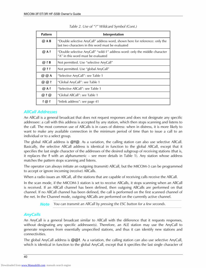
MICOM-3F/3T/3R HF-SSB Owners Guide
40
Table 2. Use of ? Wildcard Symbol (Cont.)
Pattern Interpretation
@ A B Double selective AnyCall address word, shown here for reference: only the last two characters in this word must be evaluated
@ A ? Double selective AnyCall wild-1 address word: only the middle character A in this word must be evaluated
@ ? B Not permitted. Use selective AnyCall
@ ? ? Not permitted. Use global AnyCall
@ @ A Selective AnyCall: see Table 1
@ @ ? Global AnyCall: see Table 1
@ A ? Selective AllCall: see Table 1
@ ? @ Global AllCall: see Table 1
? @ ? Inlink address: see page 41
AllCall Addresses An AllCall is a general broadcast that does not request responses and does not designate any specific addressee: a call with this address is accepted by any station, which then stops scanning and listens to the call. The most common use of AllCalls is in cases of distress: when in distress, it is more likely to want to make any available connection in the minimum period of time than to issue a call to an individual or to a select group.
The global AllCall address is @?@. As a variation, the calling station can also use selective AllCall. Basically, the selective AllCall address is identical in function to the global AllCall, except that it specifies the last single character of the addresses of the desired subgroup of receiving stations (that is, it replaces the ? with an alphanumeric see more details in Table 1). Any station whose address matches the pattern stops scanning and listens.
The operator can always initiate an outgoing (transmit) AllCall, but the MICOM-3 can be programmed to accept or ignore incoming (receive) AllCalls.
When a radio issues an AllCall, all the stations that are capable of receiving calls receive the AllCall.
In the scan mode, if the MICOM-3 station is set to receive AllCalls, it stops scanning when an AllCall is received. If an AllCall channel has been defined, then outgoing AllCalls are performed on that channel. If no AllCall channel has been defined, the call is performed on the first scanned channel of the net. In the Channel mode, outgoing AllCalls are performed on the currently active channel.
Note You can transmit an AllCall by pressing the ESC button for a few seconds.
AnyCalls An AnyCall is a general broadcast similar to AllCall with the difference that it requests responses, without designating any specific addressee(s). Therefore, an ALE station may use the AnyCall to generate responses from essentially unspecified stations, and thus it can identify new stations and connectivities.
The global AnyCall address is @@?. As a variation, the calling station can also use selective AnyCall, which is identical in function to the global AnyCall, except that it specifies the last single character of
Downloaded from www.Manualslib.com manuals search engine
Using Automatic Link Establishment (ALE)
41
the addresses of the desired subset of receiving stations (that is, it replaces the ? with an alphanumeric see more details in Table 1). If even narrower acceptance and response criteria are required, double selective AnyCall may be used: this is identical to selective AnyCall, except that its special address (@AB) specifies the last two characters that the desired subset of receiving stations.
The operator can always initiate an outgoing (transmit) AnyCall, but the MICOM-3 can be programmed to accept or ignore incoming (receive) AnyCalls.
Any station accepting an AnyCall stops scanning, and then initiates a response in a randomly selected timeslot.
Self Addresses Stations can also use their own self addresses when making calls. This may be useful for self-test and maintenance purposes, etc.
The self address may be used only in specifically-addressed calls including a group call, but not in an AllCall or AnyCall.
Null Address The null address is a special type of address that is not directed to, accepted by, or responded to by any station.
This address is intended for test and maintenance purposes, and to provide buffer time: for example, if a null address appears in a group call, no station will respond in the associated timeslot.
Inlink Address The inlink address, ?@?, is used to instruct all the stations participating in an already established link to accept and act upon the information sent with the inlink address. For example, any station can use the inlink address to send an AMD message that all the linked stations would present to their user.
The inlink address is recognized only after a link is established between two or more stations.
Using the MultiNet Feature Normally, a radio operating in the ALE mode receives and transmits only in its currently selected net. However, there are operational scenarios in which it is beneficial to enable radios to use the ALE functions while still being aware of what is going on in additional nets (for example, firefighters and paramedics must often respond to the same emergency), and be able of answering a call in another net. For this purpose, MICOM-3 radios offer the MultiNet feature.
When the MultiNet feature is enabled, a MICOM-3 radio can operate on multiple nets (up to 20). The operating characteristics then change as follows:
• Channels: each net has a group of assigned (receiving and associated transmitting) frequencies. The radio scans the channels in one net after the other, until all the nets have been scanned.
• Station addresses (the self-address and the net address used when responding to calls): the radio responds according to the self-address assigned to the station in its currently selected net (for a total of up to 20 self-addresses).
• Sounding: each radio sends soundings only within the currently selected net. Each radio scans all the channels in the currently selected net, one by one. Sounding is started 10 minutes after the unit is switched on. The sounding group interval is determined according to the programmed Sounding Auto Time.
Downloaded from www.Manualslib.com manuals search engine
MICOM-3F/3T/3R HF-SSB Owners Guide
42
During operation, the MICOM radio scans all the frequencies included in the defined nets:
• When the radio receives a call, it responds with the self-address that is programmed in the radio for that net.
• When initiating a call, you select the net you want to transmit to, and then select an address (a specific station, or any other type of address you wish to use). The radio then looks up the frequencies that are associated with the station you call and uses only those frequencies to call that station.
• LQA exchanges and sounding use only frequencies associated with the currently selected net. Note that the time needed to scan multiple nets may be rather long, even when using the rather fast 5 channels/second scan rate. Moreover, the duration of a call set up request must also be long enough to ensure that your call reaches all the relevant nets. You can use the MaxScanCh parameter (an ALE programming option) to change the duration: the default, when AUTO is selected, is about 7 seconds; however you can select a different value, in the range of 1 to 59 seconds. Make sure to use the minimum value that ensures all the nets will hear your call set up request, because long durations are very disruptive.
Messages The ALE enables you to create, send or receive alphanumeric messages (paging messages) in accordance with the AMD (Automatic Display Message) definition in Federal Standard FS-1045.
The messages are displayed on the receiving station LCD display, and can be up to 90 characters long. Messages can be added to any type of call, whether individual, group, net, AllCall, AnyCall, bidirectional handshake, etc. You can create up to 12 messages, and can edit or erase any of the messages at any time.
Using the Caller Stack The caller stack is an internal memory that stores a list of unanswered calls. Each stack entry contains the self address of the calling station and a message (AMD) if any was sent. You can view the list, return a call and view any message sent with any call.
The stack can contain up to 10 calls. The radio records an address in the stack only once even if the same caller makes repeated unanswered calls. However, if the same caller sent calls with different messages, all such calls will be saved in the stack. Each stack entry is referred to as a Page.
The appearance of the word STAK next to one of the function buttons of the LCD display indicates that there is at least one call in the stack. The STAK indicator is automatically turned off when all pages in the stack have been erased.
The stack is arranged in FIFO order, that is, the first address that enters the stack is also the first that you see on the display. If the stack is full and a new call is received, the oldest call in the stack is automatically erased.
For convenience, addresses appearing in the stack can be easily added to the ALE address directory.
Quick Call During a call, the radio saves the latest destination information as the quick call information. When the user presses the PTT of the microphone or handset twice in rapid sequence, the radio automatically directs the call to that address.
In the ALE mode, channel information is also retained and used for quick calls.
Downloaded from www.Manualslib.com manuals search engine
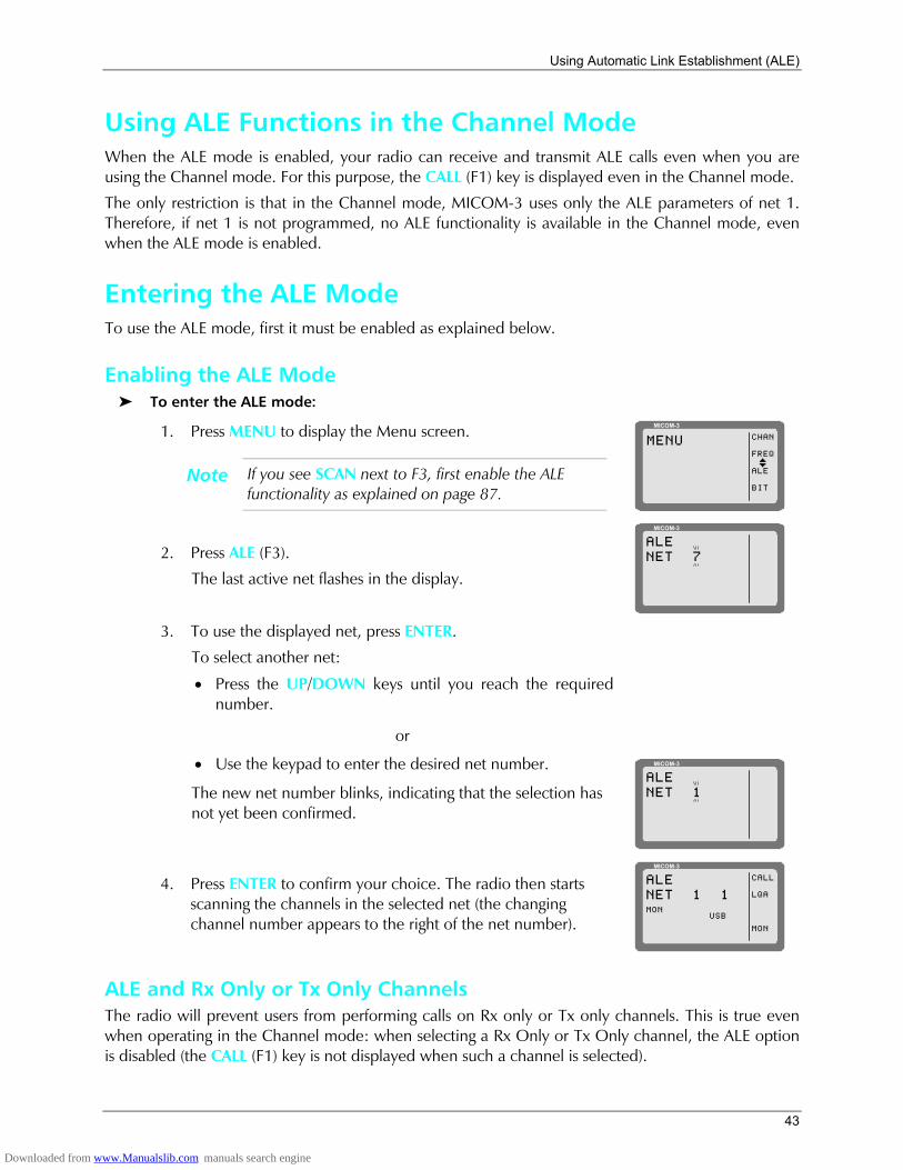
Using Automatic Link Establishment (ALE)
43
Using ALE Functions in the Channel Mode When the ALE mode is enabled, your radio can receive and transmit ALE calls even when you are using the Channel mode. For this purpose, the CALL (F1) key is displayed even in the Channel mode.
The only restriction is that in the Channel mode, MICOM-3 uses only the ALE parameters of net 1. Therefore, if net 1 is not programmed, no ALE functionality is available in the Channel mode, even when the ALE mode is enabled.
Entering the ALE Mode To use the ALE mode, first it must be enabled as explained below.
Enabling the ALE Mode To enter the ALE mode:
1. Press MENU to display the Menu screen.
Note If you see SCAN next to F3, first enable the ALE functionality as explained on page 87.
MICOM-3
CHAN
FREQ
ALE
BIT
MENU
I
2. Press ALE (F3).
The last active net flashes in the display.
MICOM-3
ALENET 7
3. To use the displayed net, press ENTER.
To select another net:
• Press the UP/DOWN keys until you reach the required number.
or
• Use the keypad to enter the desired net number.
The new net number blinks, indicating that the selection has not yet been confirmed.
MICOM-3
ALENET 1
4. Press ENTER to confirm your choice. The radio then starts scanning the channels in the selected net (the changing channel number appears to the right of the net number).
MICOM-3
CALL
LQA
MON
ALENET 1 1
USBMON
ALE and Rx Only or Tx Only Channels The radio will prevent users from performing calls on Rx only or Tx only channels. This is true even when operating in the Channel mode: when selecting a Rx Only or Tx Only channel, the ALE option is disabled (the CALL (F1) key is not displayed when such a channel is selected).
Downloaded from www.Manualslib.com manuals search engine
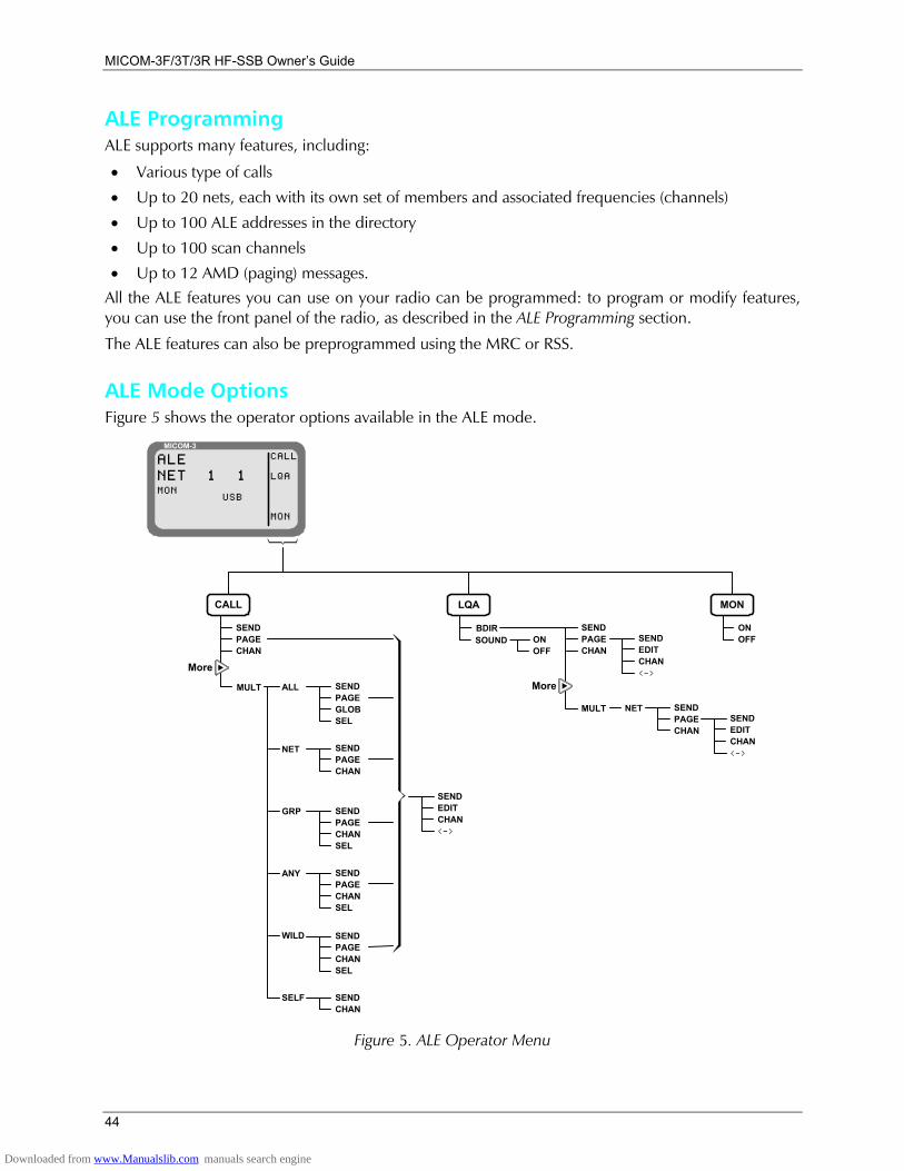
MICOM-3F/3T/3R HF-SSB Owners Guide
44
ALE Programming ALE supports many features, including:
• Various type of calls
• Up to 20 nets, each with its own set of members and associated frequencies (channels)
• Up to 100 ALE addresses in the directory
• Up to 100 scan channels
• Up to 12 AMD (paging) messages. All the ALE features you can use on your radio can be programmed: to program or modify features, you can use the front panel of the radio, as described in the ALE Programming section.
The ALE features can also be preprogrammed using the MRC or RSS.
ALE Mode Options Figure 5 shows the operator options available in the ALE mode.
MICOM-3CALL
LQA
MON
ALENET 1 1
USBMON
CALL
SENDPAGECHAN
More
ALL
NET
GRP
ANY
WILD
SELF
LQA
ONOFF
SENDPAGECHAN
MULT
More
NET SENDPAGECHAN
MON
ONOFFSEND
EDITCHAN<->
SENDEDITCHAN<->
MULT SENDPAGEGLOBSEL
SENDPAGECHAN
SENDPAGECHANSEL
SENDPAGECHANSEL
SENDPAGECHANSEL
SENDCHAN
SOUNDBDIR
SENDEDITCHAN<->
Figure 5. ALE Operator Menu
Downloaded from www.Manualslib.com manuals search engine
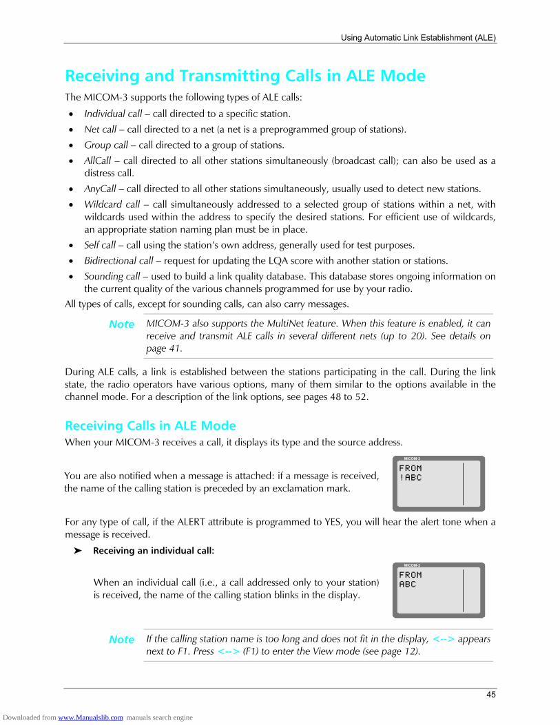
Using Automatic Link Establishment (ALE)
45
Receiving and Transmitting Calls in ALE Mode The MICOM-3 supports the following types of ALE calls:
• Individual call call directed to a specific station.
• Net call call directed to a net (a net is a preprogrammed group of stations).
• Group call call directed to a group of stations.
• AllCall call directed to all other stations simultaneously (broadcast call); can also be used as a distress call.
• AnyCall call directed to all other stations simultaneously, usually used to detect new stations.
• Wildcard call call simultaneously addressed to a selected group of stations within a net, with wildcards used within the address to specify the desired stations. For efficient use of wildcards, an appropriate station naming plan must be in place.
• Self call call using the stations own address, generally used for test purposes.
• Bidirectional call request for updating the LQA score with another station or stations.
• Sounding call used to build a link quality database. This database stores ongoing information on the current quality of the various channels programmed for use by your radio.
All types of calls, except for sounding calls, can also carry messages.
Note MICOM-3 also supports the MultiNet feature. When this feature is enabled, it can receive and transmit ALE calls in several different nets (up to 20). See details on page 41.
During ALE calls, a link is established between the stations participating in the call. During the link state, the radio operators have various options, many of them similar to the options available in the channel mode. For a description of the link options, see pages 48 to 52.
Receiving Calls in ALE Mode When your MICOM-3 receives a call, it displays its type and the source address.
You are also notified when a message is attached: if a message is received, the name of the calling station is preceded by an exclamation mark.
MICOM-3
FROM!ABC
For any type of call, if the ALERT attribute is programmed to YES, you will hear the alert tone when a message is received.
Receiving an individual call:
When an individual call (i.e., a call addressed only to your station) is received, the name of the calling station blinks in the display.
MICOM-3
FROMABC
Note If the calling station name is too long and does not fit in the display, <--> appears next to F1. Press <--> (F1) to enter the View mode (see page 12).
Downloaded from www.Manualslib.com manuals search engine
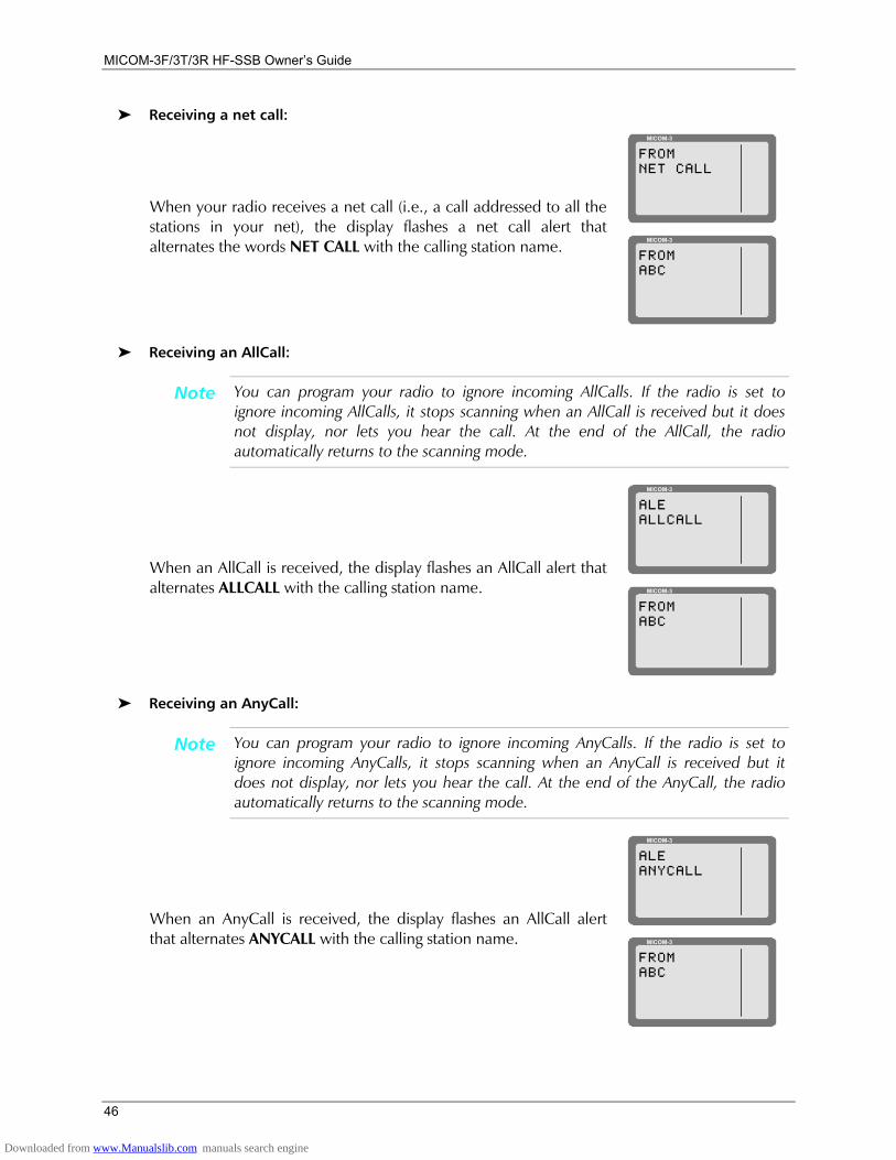
MICOM-3F/3T/3R HF-SSB Owners Guide
46
Receiving a net call:
When your radio receives a net call (i.e., a call addressed to all the stations in your net), the display flashes a net call alert that alternates the words NET CALL with the calling station name.
MICOM-3
FROMNET CALL
MICOM-3
FROMABC
Receiving an AllCall:
Note You can program your radio to ignore incoming AllCalls. If the radio is set to ignore incoming AllCalls, it stops scanning when an AllCall is received but it does not display, nor lets you hear the call. At the end of the AllCall, the radio automatically returns to the scanning mode.
When an AllCall is received, the display flashes an AllCall alert that alternates ALLCALL with the calling station name.
MICOM-3
ALEALLCALL
MICOM-3
FROMABC
Receiving an AnyCall:
Note You can program your radio to ignore incoming AnyCalls. If the radio is set to ignore incoming AnyCalls, it stops scanning when an AnyCall is received but it does not display, nor lets you hear the call. At the end of the AnyCall, the radio automatically returns to the scanning mode.
When an AnyCall is received, the display flashes an AllCall alert that alternates ANYCALL with the calling station name.
MICOM-3
ALEANYCALL
MICOM-3
FROMABC
Downloaded from www.Manualslib.com manuals search engine
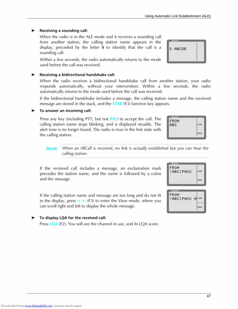
Using Automatic Link Establishment (ALE)
47
Receiving a sounding call:
When the radio is in the ALE mode and it receives a sounding call from another station, the calling station name appears in the display, preceded by the letter S to identify that the call is a sounding call.
Within a few seconds, the radio automatically returns to the mode used before the call was received.
MICOM-3
S ABCDE
Receiving a bidirectional handshake call:
When the radio receives a bidirectional handshake call from another station, your radio responds automatically, without your intervention. Within a few seconds, the radio automatically returns to the mode used before the call was received.
If the bidirectional handshake includes a message, the calling station name and the received message are stored in the stack, and the STAK (F3) function key appears.
To answer an incoming call:
Press any key (including PTT, but not ESC) to accept the call. The calling station name stops blinking, and is displayed steadily. The alert tone is no longer heard. The radio is now in the link state with the calling station.
MICOM-3
LQA
MON
FROMABC
Note When an AllCall is received, no link is actually established but you can hear the calling station.
If the received call includes a message, an exclamation mark precedes the station name, and the name is followed by a colon and the message.
MICOM-3
LQA
MON
FROM!ABC:PACK
If the calling station name and message are too long and do not fit in the display, press <-> (F3) to enter the View mode, where you can scroll right and left to display the whole message.
MICOM-3
LQA
<-->
MON
FROM!ABC:PACK A
To display LQA for the received call:
Press LQA (F2). You will see the channel in use, and its LQA score.
Downloaded from www.Manualslib.com manuals search engine
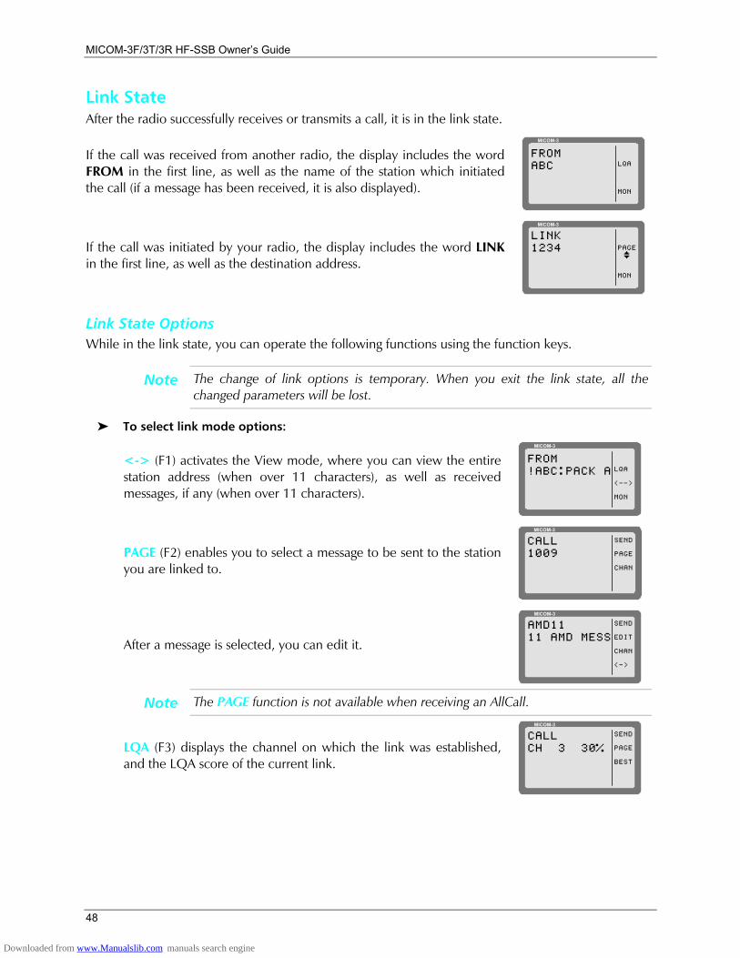
MICOM-3F/3T/3R HF-SSB Owners Guide
48
Link State After the radio successfully receives or transmits a call, it is in the link state.
If the call was received from another radio, the display includes the word FROM in the first line, as well as the name of the station which initiated the call (if a message has been received, it is also displayed).
MICOM-3
LQA
MON
FROMABC
If the call was initiated by your radio, the display includes the word LINK in the first line, as well as the destination address.
MICOM-3
PAGE
MON
LINK1234
I
Link State Options While in the link state, you can operate the following functions using the function keys.
Note The change of link options is temporary. When you exit the link state, all the changed parameters will be lost.
To select link mode options:
<-> (F1) activates the View mode, where you can view the entire station address (when over 11 characters), as well as received messages, if any (when over 11 characters).
MICOM-3
LQA
<-->
MON
FROM!ABC:PACK A
PAGE (F2) enables you to select a message to be sent to the station you are linked to.
MICOM-3
SEND
PAGE
CHAN
CALL1009
After a message is selected, you can edit it.
MICOM-3
SEND
EDIT
CHAN
<->
AMD1111 AMD MESS
Note The PAGE function is not available when receiving an AllCall.
LQA (F3) displays the channel on which the link was established, and the LQA score of the current link.
MICOM-3
SEND
PAGE
BEST
CALLCH 3 30%
Downloaded from www.Manualslib.com manuals search engine
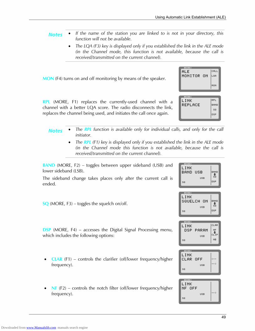
Using Automatic Link Establishment (ALE)
49
Notes • If the name of the station you are linked to is not in your directory, this function will not be available.
• The LQA (F3) key is displayed only if you established the link in the ALE mode (in the Channel mode, this function is not available, because the call is received/transmitted on the current channel).
MON (F4) turns on and off monitoring by means of the speaker.
MICOM-3
CALL
LQA
MON
ALEMONITOR ON
RPL (MORE, F1) replaces the currently-used channel with a channel with a better LQA score. The radio disconnects the link, replaces the channel being used, and initiates the call once again.
MICOM-3
RPL
BAND
SQ
DSP
LINKREPLACE
Notes • The RPL function is available only for individual calls, and only for the call initiator.
• The RPL (F1) key is displayed only if you established the link in the ALE mode (in the Channel mode this function is not available, because the call is received/transmitted on the current channel).
BAND (MORE, F2) toggles between upper sideband (USB) and lower sideband (LSB).
The sideband change takes places only after the current call is ended.
MICOM-3
BAND
SQ
DSP
LINKBAND USB
USBI
SQ
SQ (MORE, F3) toggles the squelch on/off.
MICOM-3
BAND
SQ
DSP
LINKSQUELCH ON
USBI
SQ
DSP (MORE, F4) accesses the Digital Signal Processing menu, which includes the following options:
MICOM-3
CLAR
NF
CLIP
NB
LINK DSP PARAM
USBI
SQ
• CLAR (F1) controls the clarifier (off/lower frequency/higher frequency).
MICOM-3
<--
-->
LINKCLAR OFF
USB
SQ
• NF (F2) controls the notch filter (off/lower frequency/higher frequency).
MICOM-3
-->
LINKNF OFF
USB
SQ
Downloaded from www.Manualslib.com manuals search engine
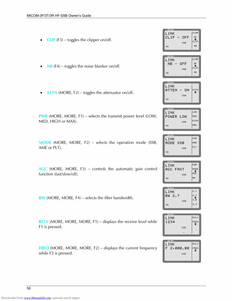
MICOM-3F/3T/3R HF-SSB Owners Guide
50
• CLIP (F3) toggles the clipper on/off.
MICOM-3
CLAR
NF
CLIP
NB
LINKCLIP - OFF
USBI
SQ
• NB (F4) toggles the noise blanker on/off.
MICOM-3
CLAR
NF
CLIP
NB
LINK NB - OFF
USBI
SQ
• ATTN (MORE, F2) toggles the attenuator on/off.
MICOM-3
ATTNLINKATTEN - ON
USBI
SQ
PWR (MORE, MORE, F1) selects the transmit power level (LOW, MED, HIGH or MAX).
MICOM-3
LOW
MED
HIGH
MAX
LINKPOWER LOW
USB
SQ
MODE (MORE, MORE, F2) selects the operation mode (SSB, AME or PLT).
MICOM-3
SSB
AME
PLT
LINKMODE SSB
USB
SQ
AGC (MORE, MORE, F3) controls the automatic gain control function (fast/slow/off).
MICOM-3
PWR
MODE
AGC
BW
LINKAGC FAST
USBI
SQ
BW (MORE, MORE, F4) selects the filter bandwidth.
MICOM-3
2.1
2.7
3.0
3.3
LINKBW 2.7
USBI
SQ
RCLV (MORE, MORE, MORE, F1) displays the receive level while F1 is pressed.
MICOM-3
RCLV
FREQ
LINK1234
IUSB
-
FREQ (MORE, MORE, MORE, F2) displays the current frequency while F2 is pressed.
MICOM-3
RCLV
FREQ
LINKF 2,000.00
IUSB
Downloaded from www.Manualslib.com manuals search engine
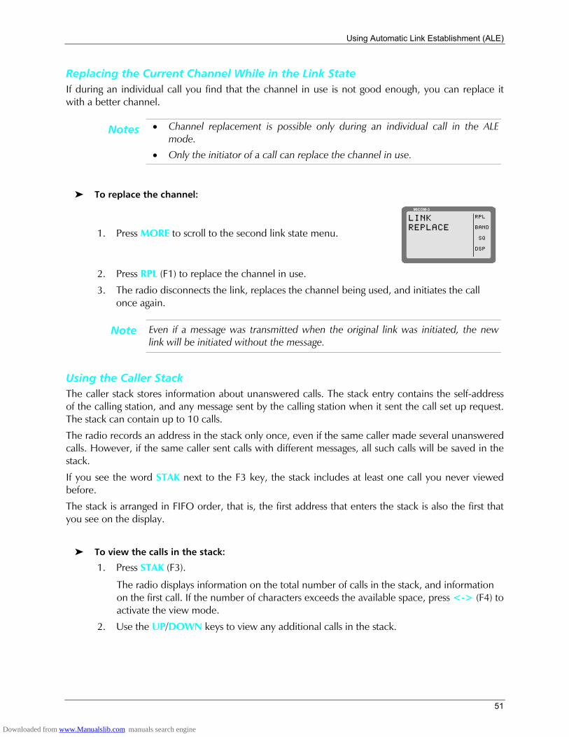
Using Automatic Link Establishment (ALE)
51
Replacing the Current Channel While in the Link State If during an individual call you find that the channel in use is not good enough, you can replace it with a better channel.
Notes • Channel replacement is possible only during an individual call in the ALE mode.
• Only the initiator of a call can replace the channel in use.
To replace the channel:
1. Press MORE to scroll to the second link state menu.
MICOM-3
RPL
BAND
SQ
DSP
LINKREPLACE
2. Press RPL (F1) to replace the channel in use.
3. The radio disconnects the link, replaces the channel being used, and initiates the call once again.
Note Even if a message was transmitted when the original link was initiated, the new link will be initiated without the message.
Using the Caller Stack The caller stack stores information about unanswered calls. The stack entry contains the self-address of the calling station, and any message sent by the calling station when it sent the call set up request. The stack can contain up to 10 calls.
The radio records an address in the stack only once, even if the same caller made several unanswered calls. However, if the same caller sent calls with different messages, all such calls will be saved in the stack.
If you see the word STAK next to the F3 key, the stack includes at least one call you never viewed before.
The stack is arranged in FIFO order, that is, the first address that enters the stack is also the first that you see on the display.
To view the calls in the stack:
1. Press STAK (F3). The radio displays information on the total number of calls in the stack, and information on the first call. If the number of characters exceeds the available space, press <-> (F4) to activate the view mode.
2. Use the UP/DOWN keys to view any additional calls in the stack.
Downloaded from www.Manualslib.com manuals search engine
MICOM-3F/3T/3R HF-SSB Owners Guide
52
To return a call to a station registered in the stack:
1. Press STAK (F3).
2. Use the UP/DOWN keys to scroll to the required call.
3. Press CALL (F1). 4. Press PAGE (F2) if you want to attach a message when you reply to the call.
5. Press CHAN (F3) if you want the call to be initiated on a specific channel in the currently used net.
Note The CHAN (F3) key is displayed only if the radio is in the ALE mode.
6. Press SEND (F1) or ENTER to initiate the call.
Note After initiating a call to a station, its page in the stack is automatically deleted, together with all other calls from the same address.
To remove an address from the stack:
The radio automatically removes an address from the stack in the following cases:
• When the operator calls a station registered in the caller stack, all stack calls containing that address are erased from the stack, regardless of whether the call was returned from within the stack or during an individual call.
• The stack can contain up to ten addresses. When the stack is full and a new address comes in, the new address replaces the oldest address in the stack.
In addition, you can manually remove an address from the stack as follows:
1. Press STAK (F3).
2. Use the UP/DOWN keys to scroll to the required call.
3. Press ERAS (F2).
4. Press YES (F1) to confirm or, NO (F2) to cancel the deletion.
Downloaded from www.Manualslib.com manuals search engine
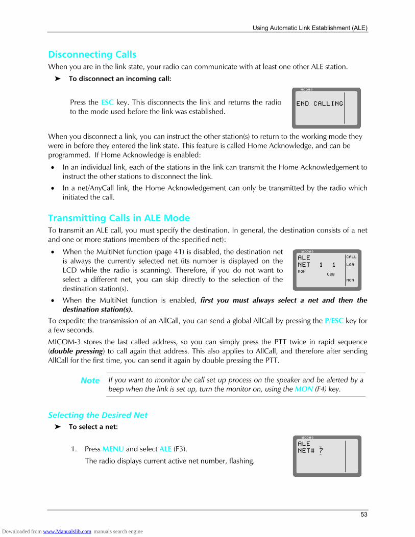
Using Automatic Link Establishment (ALE)
53
Disconnecting Calls When you are in the link state, your radio can communicate with at least one other ALE station.
To disconnect an incoming call:
Press the ESC key. This disconnects the link and returns the radio to the mode used before the link was established.
MICOM-3
END CALLING
When you disconnect a link, you can instruct the other station(s) to return to the working mode they were in before they entered the link state. This feature is called Home Acknowledge, and can be programmed. If Home Acknowledge is enabled:
• In an individual link, each of the stations in the link can transmit the Home Acknowledgement to instruct the other stations to disconnect the link.
• In a net/AnyCall link, the Home Acknowledgement can only be transmitted by the radio which initiated the call.
Transmitting Calls in ALE Mode To transmit an ALE call, you must specify the destination. In general, the destination consists of a net and one or more stations (members of the specified net):
• When the MultiNet function (page 41) is disabled, the destination net is always the currently selected net (its number is displayed on the LCD while the radio is scanning). Therefore, if you do not want to select a different net, you can skip directly to the selection of the destination station(s).
MICOM-3
CALL
LQA
MON
ALENET 1 1
USBMON
• When the MultiNet function is enabled, first you must always select a net and then the
destination station(s). To expedite the transmission of an AllCall, you can send a global AllCall by pressing the P/ESC key for a few seconds.
MICOM-3 stores the last called address, so you can simply press the PTT twice in rapid sequence (double pressing) to call again that address. This also applies to AllCall, and therefore after sending AllCall for the first time, you can send it again by double pressing the PTT.
Note If you want to monitor the call set up process on the speaker and be alerted by a beep when the link is set up, turn the monitor on, using the MON (F4) key.
Selecting the Desired Net To select a net:
1. Press MENU and select ALE (F3).
The radio displays current active net number, flashing.
MICOM-3
ALENET# 7
Downloaded from www.Manualslib.com manuals search engine
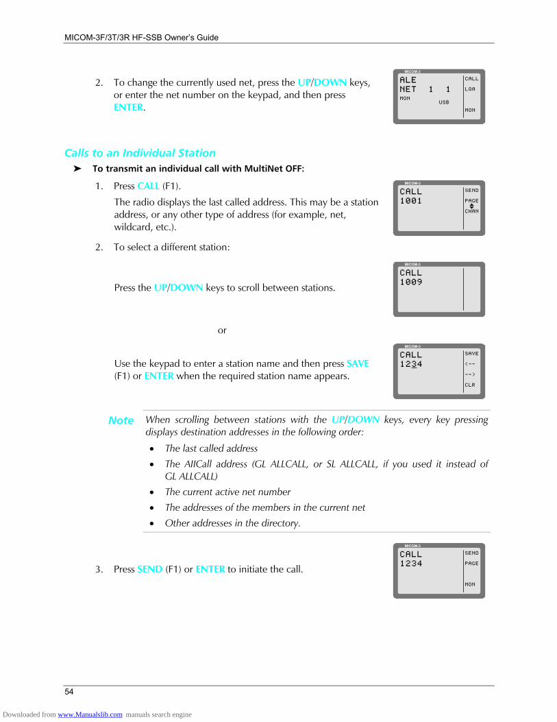
MICOM-3F/3T/3R HF-SSB Owners Guide
54
2. To change the currently used net, press the UP/DOWN keys, or enter the net number on the keypad, and then press ENTER.
MICOM-3
CALL
LQA
MON
ALENET 1 1
USBMON
Calls to an Individual Station To transmit an individual call with MultiNet OFF:
1. Press CALL (F1).
The radio displays the last called address. This may be a station address, or any other type of address (for example, net, wildcard, etc.).
MICOM-3
SEND
PAGE
CHAN
CALL1001
I
2. To select a different station:
Press the UP/DOWN keys to scroll between stations.
MICOM-3
CALL1009
or
Use the keypad to enter a station name and then press SAVE (F1) or ENTER when the required station name appears.
MICOM-3
SAVE
<--
-->
CLR
CALL1234
Note When scrolling between stations with the UP/DOWN keys, every key pressing displays destination addresses in the following order:
• The last called address
• The AIICall address (GL ALLCALL, or SL ALLCALL, if you used it instead of GL ALLCALL)
• The current active net number
• The addresses of the members in the current net
• Other addresses in the directory.
3. Press SEND (F1) or ENTER to initiate the call.
MICOM-3
SEND
PAGE
MON
CALL1234
Downloaded from www.Manualslib.com manuals search engine

Using Automatic Link Establishment (ALE)
55
4. The radio now starts the link set up process. During this process, you will see TO alternating with the number of the channel on which the set up request is being sent (the channel may change, if the called station does not answer on the first channel(s)).
Note While the radio is initializing the link, you can press STOP (F1) or ESC to abort the entire process.
MICOM-3
STOPTO1234
MICOM-3
STOPCH 21234
5. After the link is established, you will see a LINK message. Now you may press the PTT and start talking.
MICOM-3
PAGE
MON
LINK1234
I
Note If the link with the selected station cannot be set up, you will see for a few seconds a flashing NO LINK message.
6. To disconnect the link, press the ESC key (see page 48).
Note If you want to call again the same station, double-press the PTT to use the quick-call feature (see page 57).
To transmit an individual call with MultiNet ON:
1. Press CALL (F1).
The radio displays the current net number, flashing. If you wish to change the currently used net, press the UP/DOWN keys or enter the net number on the keypad.
MICOM-3
ALENET# 7
2. Press ENTER to confirm the net number.
3. The radio displays the last called station.
MICOM-3
SEND
PAGE
CHAN
CALL1001
I
Press the UP/DOWN keys to scroll between stations, or use the keypad to enter a station name and then press SAVE (F1) or ENTER when the required station name appears.
MICOM-3
SEND
PAGE
CHAN
CALL1009
I
4. Press SEND (F1) or ENTER to initiate the call.
5. The radio now starts the link set up process. During this process, you will see TO alternating with the number of the channel the set up request is being sent (the channel may change, if the called station does not answer on the first channel(s)).
Downloaded from www.Manualslib.com manuals search engine

MICOM-3F/3T/3R HF-SSB Owners Guide
56
Note While the radio is initializing the link, you can press STOP (F1) or ESC to abort the entire process.
6. After the link is established, you will see a LINK message. Now you may press the PTT and start talking.
7. To disconnect the link, press the ESC key (see page 48).
To transmit on a specific channel:
1. Initiate a call as explained above (page 54 or 55) and select the desired station.
MICOM-3
SEND
PAGE
CHAN
CALL1009
I
2. Press CHAN (F3) to select a specific channel.
The channel with the best LQA score is displayed. The speaker is unmuted to enable you to check the channel quality by listening to it.
MICOM-3
SEND
PAGE
BEST
CALLCH 3 30%
Note If the name of the called station has been edited and the new station name is not in the directory, no LQA score is displayed.
3. Press BEST (F3) to select the channel with the best LQA score ...
Note If the name of the called station has been edited and the new station name is not in the directory, the channel displayed after pressing BEST (F3) is the first scanned channel of the net.
or
Press the UP/DOWN keys to scroll to the channel of your choice.
Note You can use this option to transmit a call to a station operating in the Channel mode. If the other station is in the Channel mode, your radio switches to the Channel mode for the duration of the call, and then returns to the ALE mode after the link to that station is disconnected.
4. Press SEND (F1) or ENTER to initiate the call.
5. The radio now starts the link set up process. During this process, you will see TO alternating with the number of the channel on which the set up request is being sent (the channel may change, if the called station does not answer on the first channel(s)).
Note While the radio is initializing the link, you can press STOP (F1) or ESC to abort the entire process.
6. After the link is established, you will see a LINK message. Now you may press the PTT and start talking.
7. To disconnect the link, press the ESC key (see page 48).
Downloaded from www.Manualslib.com manuals search engine
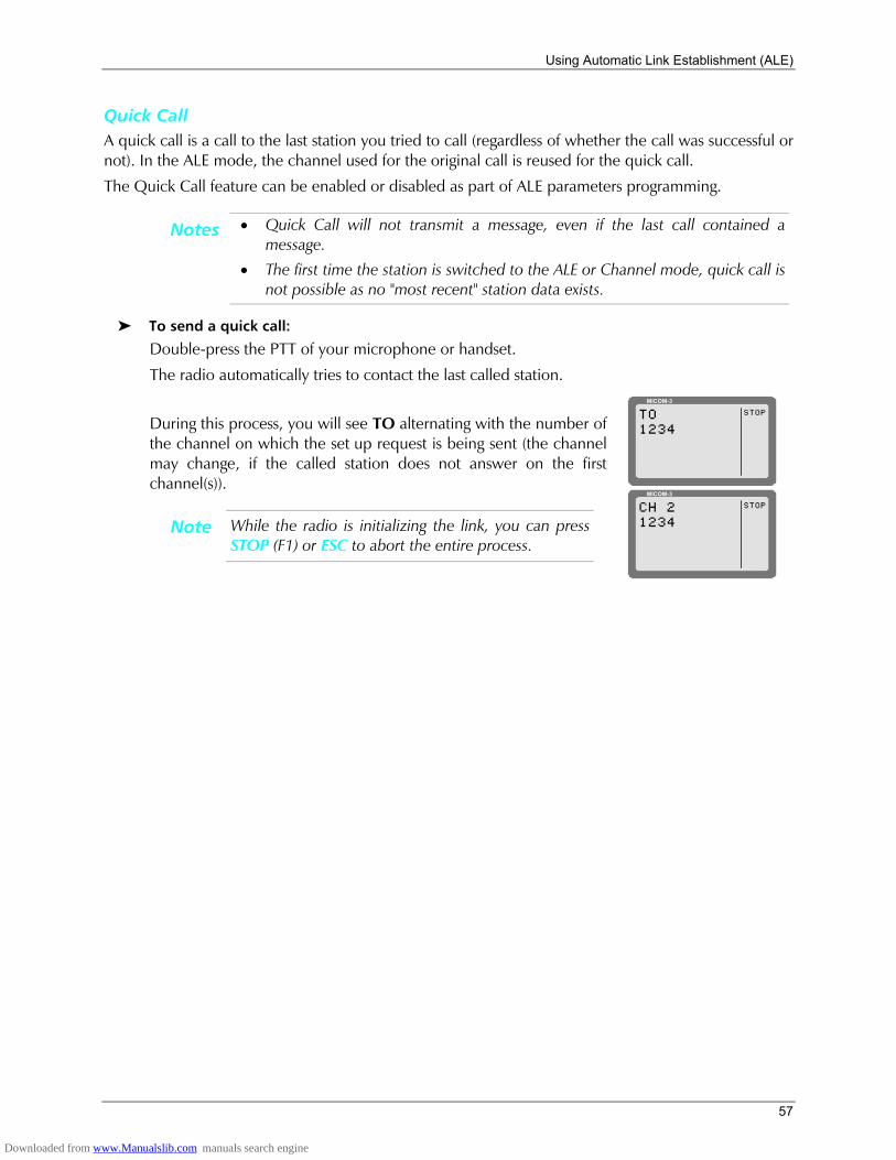
Using Automatic Link Establishment (ALE)
57
Quick Call A quick call is a call to the last station you tried to call (regardless of whether the call was successful or not). In the ALE mode, the channel used for the original call is reused for the quick call.
The Quick Call feature can be enabled or disabled as part of ALE parameters programming.
Notes • Quick Call will not transmit a message, even if the last call contained a message.
• The first time the station is switched to the ALE or Channel mode, quick call is not possible as no "most recent" station data exists.
To send a quick call:
Double-press the PTT of your microphone or handset.
The radio automatically tries to contact the last called station.
During this process, you will see TO alternating with the number of the channel on which the set up request is being sent (the channel may change, if the called station does not answer on the first channel(s)).
Note While the radio is initializing the link, you can press STOP (F1) or ESC to abort the entire process.
MICOM-3
STOPTO1234
MICOM-3
STOPCH 21234
Downloaded from www.Manualslib.com manuals search engine
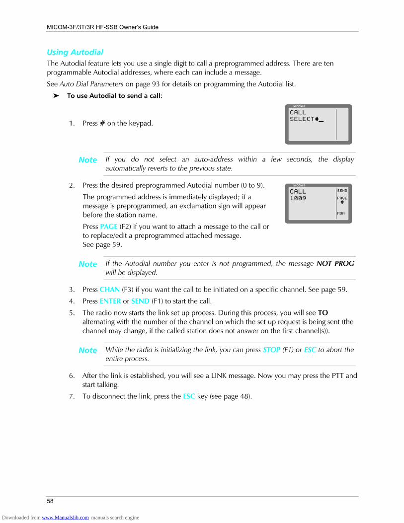
MICOM-3F/3T/3R HF-SSB Owners Guide
58
Using Autodial The Autodial feature lets you use a single digit to call a preprogrammed address. There are ten programmable Autodial addresses, where each can include a message.
See Auto Dial Parameters on page 93 for details on programming the Autodial list.
To use Autodial to send a call:
1. Press # on the keypad.
MICOM-3
CALLSELECT#_
Note If you do not select an auto-address within a few seconds, the display automatically reverts to the previous state.
2. Press the desired preprogrammed Autodial number (0 to 9).
The programmed address is immediately displayed; if a message is preprogrammed, an exclamation sign will appear before the station name.
Press PAGE (F2) if you want to attach a message to the call or to replace/edit a preprogrammed attached message. See page 59.
MICOM-3
SEND
PAGE
MON
CALL1009
I
Note If the Autodial number you enter is not programmed, the message NOT PROG will be displayed.
3. Press CHAN (F3) if you want the call to be initiated on a specific channel. See page 59.
4. Press ENTER or SEND (F1) to start the call.
5. The radio now starts the link set up process. During this process, you will see TO alternating with the number of the channel on which the set up request is being sent (the channel may change, if the called station does not answer on the first channel(s)).
Note While the radio is initializing the link, you can press STOP (F1) or ESC to abort the entire process.
6. After the link is established, you will see a LINK message. Now you may press the PTT and start talking.
7. To disconnect the link, press the ESC key (see page 48).
Downloaded from www.Manualslib.com manuals search engine
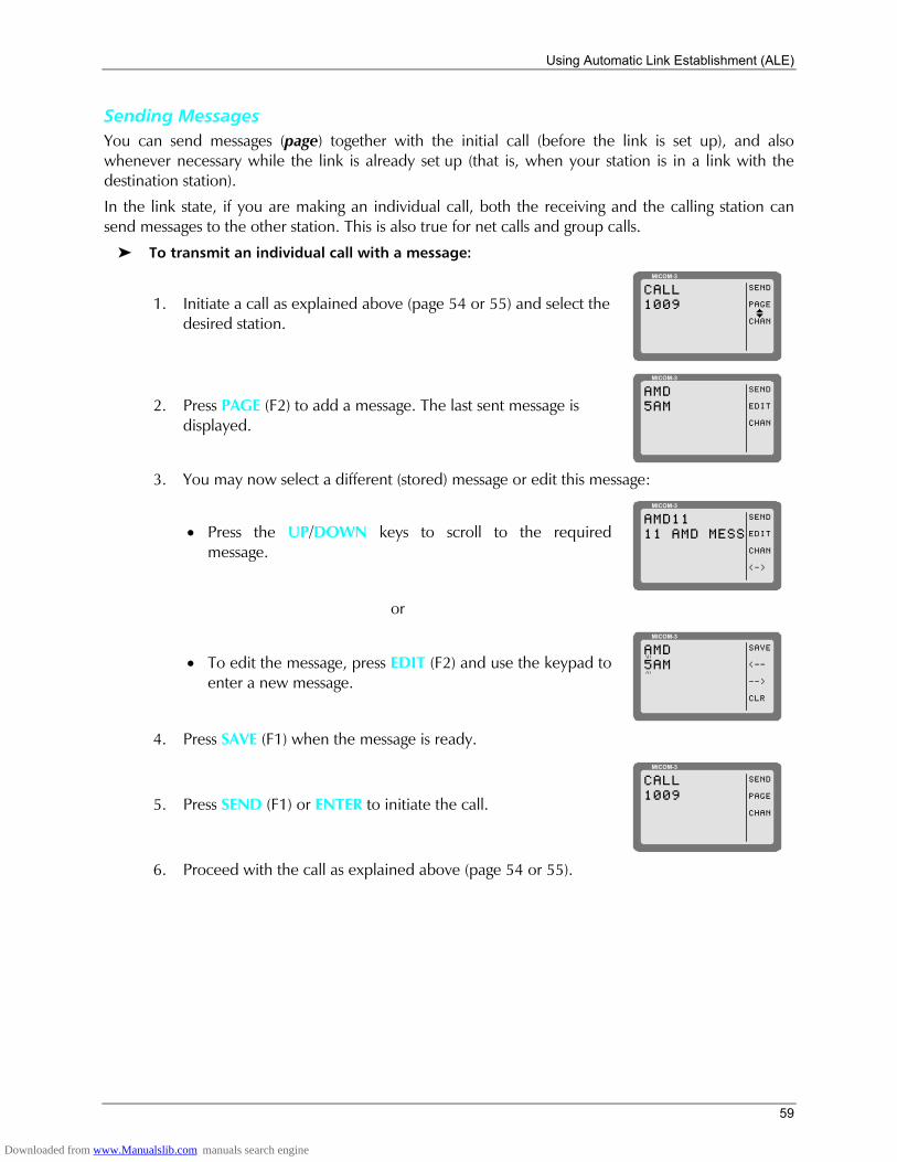
Using Automatic Link Establishment (ALE)
59
Sending Messages You can send messages (page) together with the initial call (before the link is set up), and also whenever necessary while the link is already set up (that is, when your station is in a link with the destination station).
In the link state, if you are making an individual call, both the receiving and the calling station can send messages to the other station. This is also true for net calls and group calls.
To transmit an individual call with a message:
1. Initiate a call as explained above (page 54 or 55) and select the desired station.
MICOM-3
SEND
PAGE
CHAN
CALL1009
I
2. Press PAGE (F2) to add a message. The last sent message is displayed.
MICOM-3
SEND
EDIT
CHAN
AMD5AM
3. You may now select a different (stored) message or edit this message:
• Press the UP/DOWN keys to scroll to the required message.
MICOM-3
SEND
EDIT
CHAN
<->
AMD1111 AMD MESS
or
• To edit the message, press EDIT (F2) and use the keypad to enter a new message.
MICOM-3
SAVE
<--
-->
CLR
AMD5AM
4. Press SAVE (F1) when the message is ready.
5. Press SEND (F1) or ENTER to initiate the call.
MICOM-3
SEND
PAGE
CHAN
CALL1009
6. Proceed with the call as explained above (page 54 or 55).
Downloaded from www.Manualslib.com manuals search engine
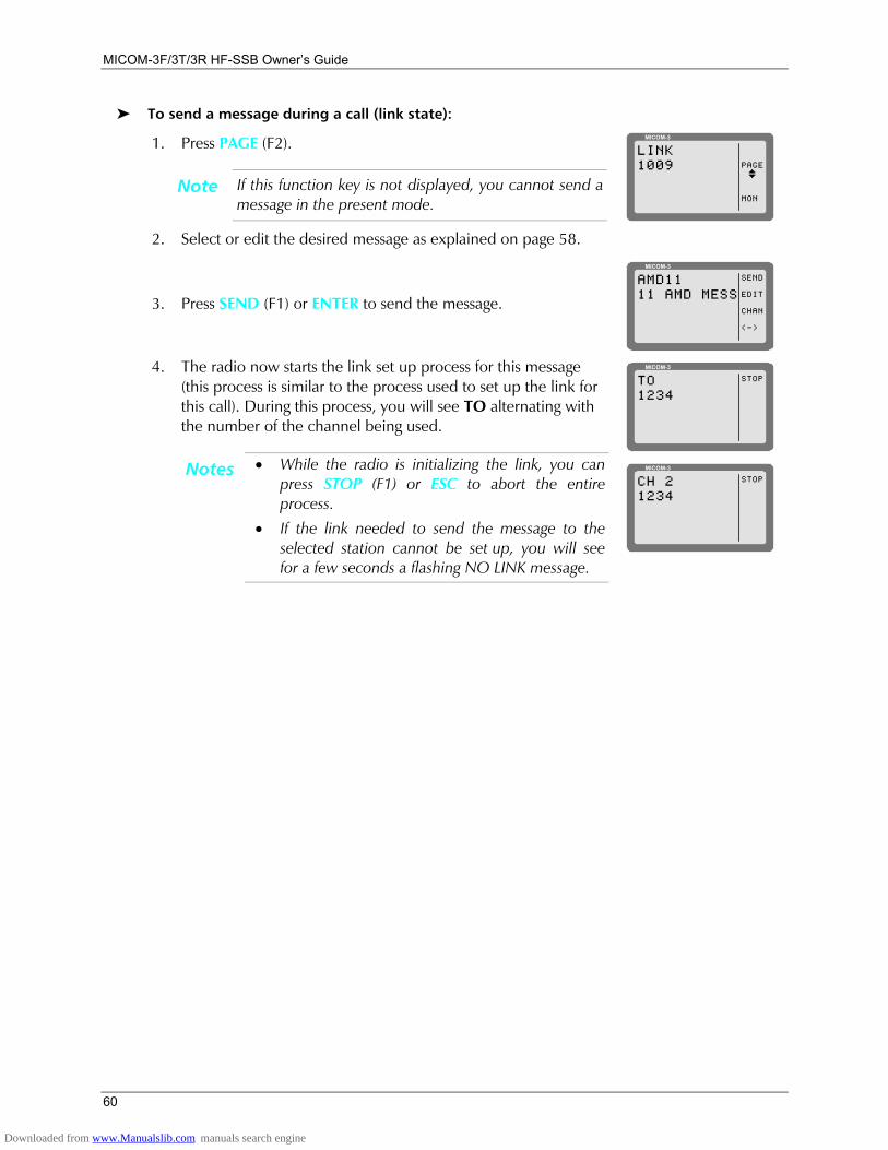
MICOM-3F/3T/3R HF-SSB Owners Guide
60
To send a message during a call (link state):
1. Press PAGE (F2).
Note If this function key is not displayed, you cannot send a message in the present mode.
MICOM-3
PAGE
MON
LINK1009
I
2. Select or edit the desired message as explained on page 58.
3. Press SEND (F1) or ENTER to send the message.
MICOM-3
SEND
EDIT
CHAN
<->
AMD1111 AMD MESS
4. The radio now starts the link set up process for this message
(this process is similar to the process used to set up the link for this call). During this process, you will see TO alternating with the number of the channel being used.
Notes • While the radio is initializing the link, you can press STOP (F1) or ESC to abort the entire process.
• If the link needed to send the message to the selected station cannot be set up, you will see for a few seconds a flashing NO LINK message.
MICOM-3
STOPTO1234
MICOM-3
STOPCH 21234
Downloaded from www.Manualslib.com manuals search engine
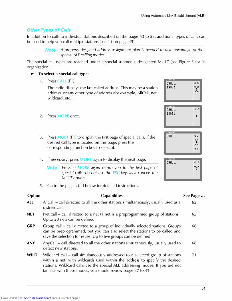
Using Automatic Link Establishment (ALE)
61
Other Types of Calls In addition to calls to individual stations described on the pages 53 to 59, additional types of calls can be used to help you call multiple stations (see list on page 45).
Note A properly designed address assignment plan is needed to take advantage of the special ALE calling modes.
The special call types are reached under a special submenu, designated MULT (see Figure 5 for its organization).
To select a special call type:
1. Press CALL (F1).
The radio displays the last called address. This may be a station address, or any other type of address (for example, AllCall, net, wildcard, etc.).
MICOM-3
SEND
PAGE
CHAN
CALL1001
I
2. Press MORE once.
MICOM-3
MULTCALL1001
I
3. Press MULT (F1) to display the first page of special calls. If the desired call type is located on this page, press the corresponding function key to select it.
MICOM-3
ALL
NET
GRP
ANY
CALL
I
4. If necessary, press MORE again to display the next page.
Note Pressing MORE again return you to the first page of special calls: do not use the ESC key, as it cancels the MULT option.
MICOM-3
WILD
SELF
CALL
I
5. Go to the page listed below for detailed instructions.
Option Capabilities See Page
ALL AllCall call directed to all the other stations simultaneously; usually used as a distress call.
62
NET Net call call directed to a net (a net is a preprogrammed group of stations). Up to 20 nets can be defined.
65
GRP Group call call directed to a group of individually selected stations. Groups can be preprogrammed, but you can also select the stations to be called and save the selection for reuse. Up to five groups can be defined.
66
ANY AnyCall call directed to all the other stations simultaneously, usually used to detect new stations.
68
WILD Wildcard call call simultaneously addressed to a selected group of stations within a net, with wildcards used within the address to specify the desired stations. Wildcard calls use the special ALE addressing modes. If you are not familiar with these modes, you should review pages 37 to 41.
71
Downloaded from www.Manualslib.com manuals search engine
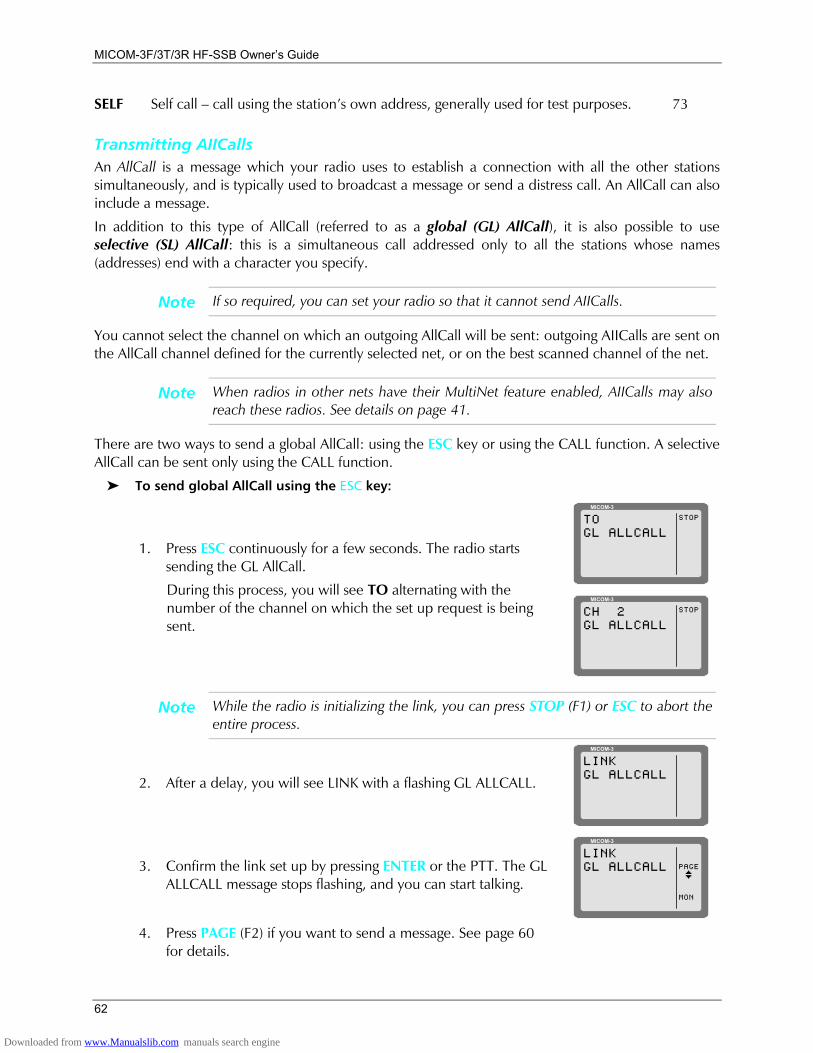
MICOM-3F/3T/3R HF-SSB Owners Guide
62
SELF Self call call using the stations own address, generally used for test purposes. 73
Transmitting AIICalls An AllCall is a message which your radio uses to establish a connection with all the other stations simultaneously, and is typically used to broadcast a message or send a distress call. An AllCall can also include a message.
In addition to this type of AllCall (referred to as a global (GL) AllCall), it is also possible to use selective (SL) AllCall: this is a simultaneous call addressed only to all the stations whose names (addresses) end with a character you specify.
Note If so required, you can set your radio so that it cannot send AIICalls.
You cannot select the channel on which an outgoing AllCall will be sent: outgoing AIICalls are sent on the AllCall channel defined for the currently selected net, or on the best scanned channel of the net.
Note When radios in other nets have their MultiNet feature enabled, AIICalls may also reach these radios. See details on page 41.
There are two ways to send a global AllCall: using the ESC key or using the CALL function. A selective AllCall can be sent only using the CALL function.
To send global AllCall using the ESC key:
1. Press ESC continuously for a few seconds. The radio starts sending the GL AllCall.
During this process, you will see TO alternating with the number of the channel on which the set up request is being sent.
MICOM-3
STOPTOGL ALLCALL
MICOM-3
STOPCH 2GL ALLCALL
Note While the radio is initializing the link, you can press STOP (F1) or ESC to abort the entire process.
2. After a delay, you will see LINK with a flashing GL ALLCALL.
MICOM-3
LINKGL ALLCALL
3. Confirm the link set up by pressing ENTER or the PTT. The GL ALLCALL message stops flashing, and you can start talking.
MICOM-3
PAGE
MON
LINKGL ALLCALL
I
4. Press PAGE (F2) if you want to send a message. See page 60
for details.
Downloaded from www.Manualslib.com manuals search engine
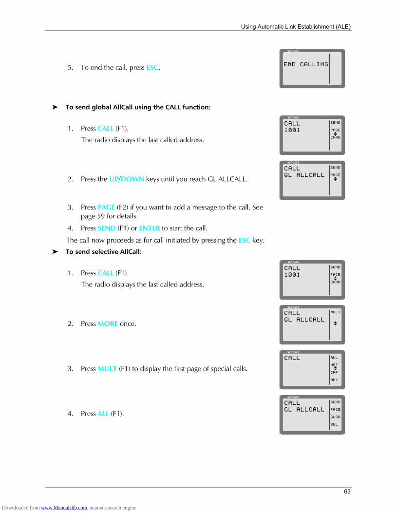
Using Automatic Link Establishment (ALE)
63
5. To end the call, press ESC.
MICOM-3
END CALLING
To send global AllCall using the CALL function:
1. Press CALL (F1).
The radio displays the last called address.
MICOM-3
SEND
PAGE
CHAN
CALL1001
I
2. Press the UP/DOWN keys until you reach GL ALLCALL.
MICOM-3
SEND
PAGE
CALLGL ALLCALL
I
3. Press PAGE (F2) if you want to add a message to the call. See
page 59 for details.
4. Press SEND (F1) or ENTER to start the call. The call now proceeds as for call initiated by pressing the ESC key.
To send selective AllCall:
1. Press CALL (F1).
The radio displays the last called address.
MICOM-3
SEND
PAGE
CHAN
CALL1001
I
2. Press MORE once.
MICOM-3
MULTCALLGL ALLCALL
I
3. Press MULT (F1) to display the first page of special calls.
MICOM-3
ALL
NET
GRP
ANY
CALL
I
4. Press ALL (F1).
MICOM-3
SEND
PAGE
GLOB
SEL
CALLGL ALLCALL
Downloaded from www.Manualslib.com manuals search engine
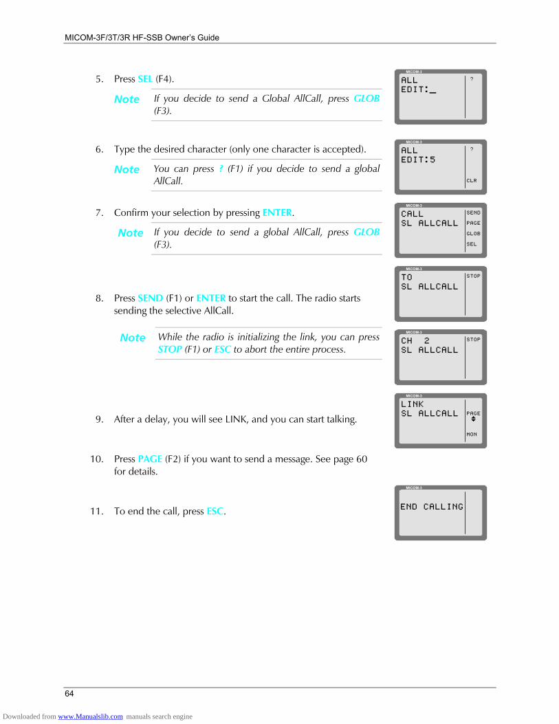
MICOM-3F/3T/3R HF-SSB Owners Guide
64
5. Press SEL (F4).
Note If you decide to send a Global AllCall, press GLOB (F3).
MICOM-3
?ALLEDIT:_
6. Type the desired character (only one character is accepted).
Note You can press ? (F1) if you decide to send a global AllCall.
MICOM-3
?
CLR
ALLEDIT:5
7. Confirm your selection by pressing ENTER.
Note If you decide to send a global AllCall, press GLOB (F3).
MICOM-3
SEND
PAGE
GLOB
SEL
CALLSL ALLCALL
8. Press SEND (F1) or ENTER to start the call. The radio starts sending the selective AllCall.
Note While the radio is initializing the link, you can press STOP (F1) or ESC to abort the entire process.
MICOM-3
STOPTOSL ALLCALL
MICOM-3
STOPCH 2SL ALLCALL
9. After a delay, you will see LINK, and you can start talking.
MICOM-3
PAGE
MON
LINKSL ALLCALL
I
10. Press PAGE (F2) if you want to send a message. See page 60
for details.
11. To end the call, press ESC.
MICOM-3
END CALLING
Downloaded from www.Manualslib.com manuals search engine
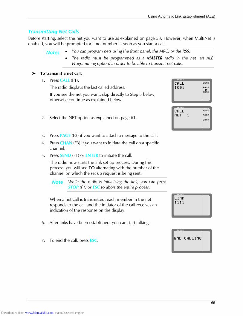
Using Automatic Link Establishment (ALE)
65
Transmitting Net Calls Before starting, select the net you want to use as explained on page 53. However, when MultiNet is enabled, you will be prompted for a net number as soon as you start a call.
Notes • You can program nets using the front panel, the MRC, or the RSS.
• The radio must be programmed as a MASTER radio in the net (an ALE Programming option) in order to be able to transmit net calls.
To transmit a net call:
1. Press CALL (F1).
The radio displays the last called address.
If you see the net you want, skip directly to Step 5 below, otherwise continue as explained below.
MICOM-3
SEND
PAGE
CHAN
CALL1001
I
2. Select the NET option as explained on page 61.
MICOM-3
SEND
PAGE
CHAN
CALLNET 1
3. Press PAGE (F2) if you want to attach a message to the call. 4. Press CHAN (F3) if you want to initiate the call on a specific
channel.
5. Press SEND (F1) or ENTER to initiate the call.
The radio now starts the link set up process. During this process, you will see TO alternating with the number of the channel on which the set up request is being sent.
Note While the radio is initializing the link, you can press STOP (F1) or ESC to abort the entire process.
When a net call is transmitted, each member in the net responds to the call and the initiator of the call receives an indication of the response on the display.
MICOM-3
LINK1111
6. After links have been established, you can start talking.
7. To end the call, press ESC.
MICOM-3
END CALLING
Downloaded from www.Manualslib.com manuals search engine
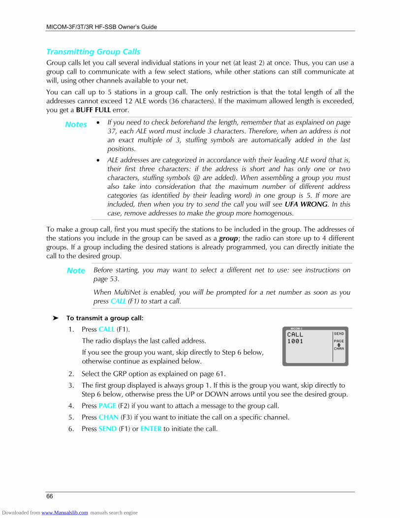
MICOM-3F/3T/3R HF-SSB Owners Guide
66
Transmitting Group Calls Group calls let you call several individual stations in your net (at least 2) at once. Thus, you can use a group call to communicate with a few select stations, while other stations can still communicate at will, using other channels available to your net.
You can call up to 5 stations in a group call. The only restriction is that the total length of all the addresses cannot exceed 12 ALE words (36 characters). If the maximum allowed length is exceeded, you get a BUFF FULL error.
Notes • If you need to check beforehand the length, remember that as explained on page 37, each ALE word must include 3 characters. Therefore, when an address is not an exact multiple of 3, stuffing symbols are automatically added in the last positions.
• ALE addresses are categorized in accordance with their leading ALE word (that is, their first three characters: if the address is short and has only one or two characters, stuffing symbols @ are added). When assembling a group you must also take into consideration that the maximum number of different address categories (as identified by their leading word) in one group is 5. If more are included, then when you try to send the call you will see UFA WRONG. In this case, remove addresses to make the group more homogenous.
To make a group call, first you must specify the stations to be included in the group. The addresses of the stations you include in the group can be saved as a group; the radio can store up to 4 different groups. If a group including the desired stations is already programmed, you can directly initiate the call to the desired group.
Note Before starting, you may want to select a different net to use: see instructions on page 53.
When MultiNet is enabled, you will be prompted for a net number as soon as you press CALL (F1) to start a call.
To transmit a group call:
1. Press CALL (F1).
The radio displays the last called address.
If you see the group you want, skip directly to Step 6 below, otherwise continue as explained below.
MICOM-3
SEND
PAGE
CHAN
CALL1001
I
2. Select the GRP option as explained on page 61.
3. The first group displayed is always group 1. If this is the group you want, skip directly to Step 6 below, otherwise press the UP or DOWN arrows until you see the desired group.
4. Press PAGE (F2) if you want to attach a message to the group call.
5. Press CHAN (F3) if you want to initiate the call on a specific channel.
6. Press SEND (F1) or ENTER to initiate the call.
Downloaded from www.Manualslib.com manuals search engine
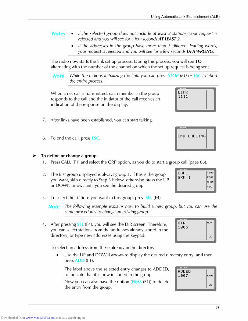
Using Automatic Link Establishment (ALE)
67
Notes • If the selected group does not include at least 2 stations, your request is rejected and you will see for a few seconds AT LEAST 2.
• If the addresses in the group have more than 5 different leading words, your request is rejected and you will see for a few seconds UFA WRONG.
The radio now starts the link set up process. During this process, you will see TO alternating with the number of the channel on which the set up request is being sent.
Note While the radio is initializing the link, you can press STOP (F1) or ESC to abort the entire process.
When a net call is transmitted, each member in the group responds to the call and the initiator of the call receives an indication of the response on the display.
MICOM-3
LINK1111
7. After links have been established, you can start talking.
8. To end the call, press ESC.
MICOM-3
END CALLING
To define or change a group:
1. Press CALL (F1) and select the GRP option, as you do to start a group call (page 66).
2. The first group displayed is always group 1. If this is the group you want, skip directly to Step 3 below, otherwise press the UP or DOWN arrows until you see the desired group.
MICOM-3
SEND
PAGE
CHAN
SEL
CALLGRP 1
3. To select the stations you want in this group, press SEL (F4).
Note The following example explains how to build a new group, but you can use the same procedures to change an existing group.
4. After pressing SEL (F4), you will see the DIR screen. Therefore, you can select stations from the addresses already stored in the directory, or type new addresses using the keypad.
MICOM-3
ADD
OK
DIR1005
To select an address from these already in the directory:
• Use the UP and DOWN arrows to display the desired directory entry, and then press ADD (F1).
The label above the selected entry changes to ADDED, to indicate that it is now included in the group.
Now you can also have the option (ERAS (F1)) to delete the entry from the group.
MICOM-3
ERAS
OK
ADDED1007
Downloaded from www.Manualslib.com manuals search engine
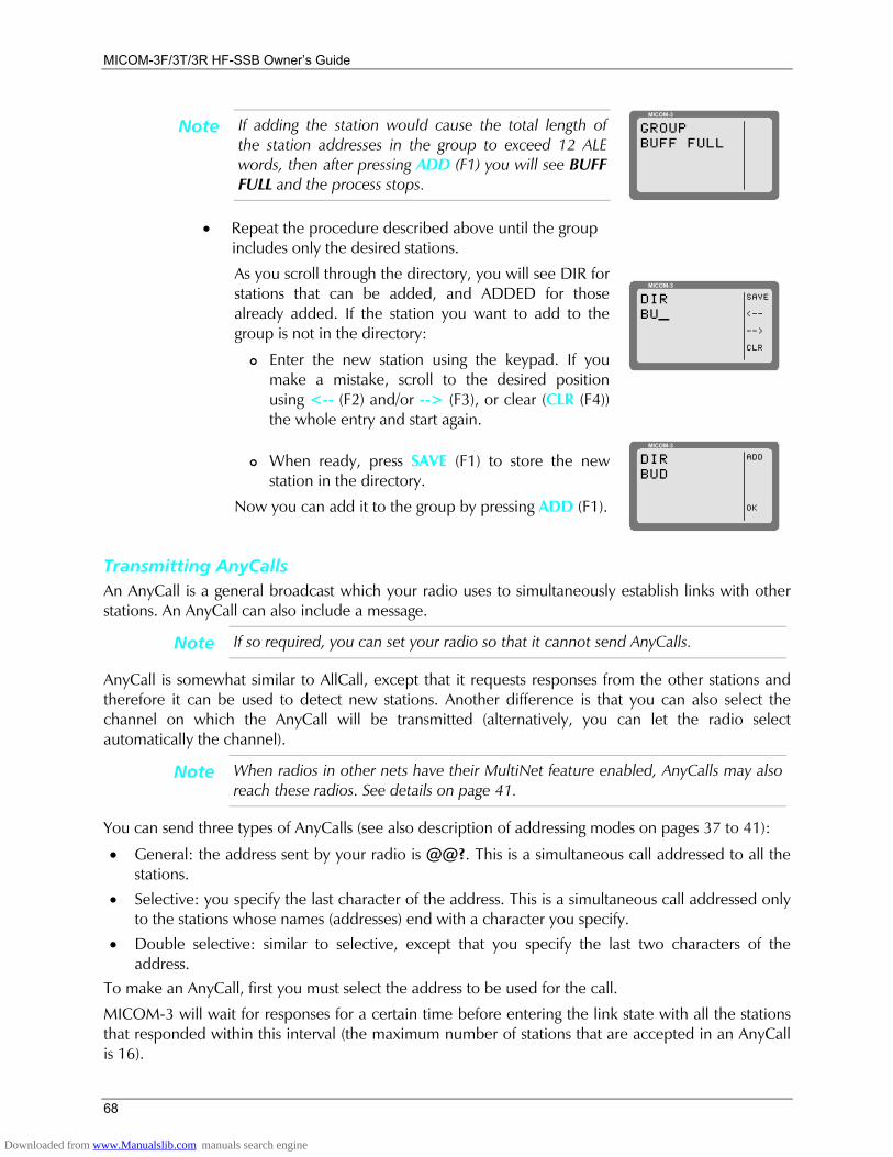
MICOM-3F/3T/3R HF-SSB Owners Guide
68
Note If adding the station would cause the total length of the station addresses in the group to exceed 12 ALE words, then after pressing ADD (F1) you will see BUFF FULL and the process stops.
MICOM-3
GROUPBUFF FULL
• Repeat the procedure described above until the group includes only the desired stations.
As you scroll through the directory, you will see DIR for stations that can be added, and ADDED for those already added. If the station you want to add to the group is not in the directory:
!"Enter the new station using the keypad. If you make a mistake, scroll to the desired position using <-- (F2) and/or --> (F3), or clear (CLR (F4)) the whole entry and start again.
MICOM-3
SAVE
<--
-->
CLR
DIRBU_
!"When ready, press SAVE (F1) to store the new station in the directory.
Now you can add it to the group by pressing ADD (F1).
MICOM-3
ADD
OK
DIRBUD
Transmitting AnyCalls An AnyCall is a general broadcast which your radio uses to simultaneously establish links with other stations. An AnyCall can also include a message.
Note If so required, you can set your radio so that it cannot send AnyCalls.
AnyCall is somewhat similar to AllCall, except that it requests responses from the other stations and therefore it can be used to detect new stations. Another difference is that you can also select the channel on which the AnyCall will be transmitted (alternatively, you can let the radio select automatically the channel).
Note When radios in other nets have their MultiNet feature enabled, AnyCalls may also reach these radios. See details on page 41.
You can send three types of AnyCalls (see also description of addressing modes on pages 37 to 41):
• General: the address sent by your radio is @@?. This is a simultaneous call addressed to all the stations.
• Selective: you specify the last character of the address. This is a simultaneous call addressed only to the stations whose names (addresses) end with a character you specify.
• Double selective: similar to selective, except that you specify the last two characters of the address.
To make an AnyCall, first you must select the address to be used for the call.
MICOM-3 will wait for responses for a certain time before entering the link state with all the stations that responded within this interval (the maximum number of stations that are accepted in an AnyCall is 16).
Downloaded from www.Manualslib.com manuals search engine
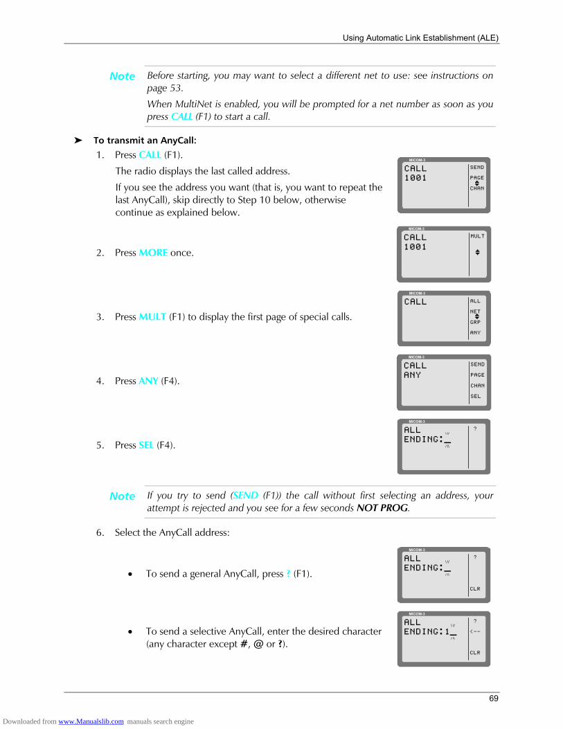
Using Automatic Link Establishment (ALE)
69
Note Before starting, you may want to select a different net to use: see instructions on page 53.
When MultiNet is enabled, you will be prompted for a net number as soon as you press CALL (F1) to start a call.
To transmit an AnyCall:
1. Press CALL (F1).
The radio displays the last called address.
If you see the address you want (that is, you want to repeat the last AnyCall), skip directly to Step 10 below, otherwise continue as explained below.
MICOM-3
SEND
PAGE
CHAN
CALL1001
I
2. Press MORE once.
MICOM-3
MULTCALL1001
I
3. Press MULT (F1) to display the first page of special calls.
MICOM-3
ALL
NET
GRP
ANY
CALL
I
4. Press ANY (F4).
MICOM-3
SEND
PAGE
CHAN
SEL
CALLANY
5. Press SEL (F4).
MICOM-3
?ALLENDING:_
Note If you try to send (SEND (F1)) the call without first selecting an address, your attempt is rejected and you see for a few seconds NOT PROG.
6. Select the AnyCall address:
• To send a general AnyCall, press ? (F1).
MICOM-3
?
CLR
ALLENDING:_
• To send a selective AnyCall, enter the desired character (any character except #, @ or ?).
MICOM-3
?
<--
CLR
ALLENDING:1_
Downloaded from www.Manualslib.com manuals search engine
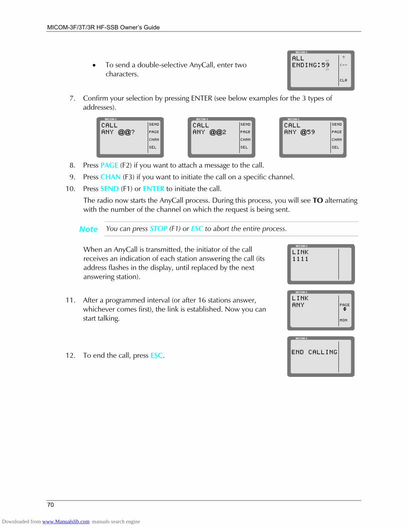
MICOM-3F/3T/3R HF-SSB Owners Guide
70
• To send a double-selective AnyCall, enter two characters.
MICOM-3
?
<--
CLR
ALLENDING:59
7. Confirm your selection by pressing ENTER (see below examples for the 3 types of
addresses). MICOM-3
SEND
PAGE
CHAN
SEL
CALLANY @@?
MICOM-3
SEND
PAGE
CHAN
SEL
CALLANY @@2
MICOM-3
SEND
PAGE
CHAN
SEL
CALLANY @59
8. Press PAGE (F2) if you want to attach a message to the call.
9. Press CHAN (F3) if you want to initiate the call on a specific channel.
10. Press SEND (F1) or ENTER to initiate the call.
The radio now starts the AnyCall process. During this process, you will see TO alternating with the number of the channel on which the request is being sent.
Note You can press STOP (F1) or ESC to abort the entire process.
When an AnyCall is transmitted, the initiator of the call receives an indication of each station answering the call (its address flashes in the display, until replaced by the next answering station).
MICOM-3
LINK1111
11. After a programmed interval (or after 16 stations answer, whichever comes first), the link is established. Now you can start talking.
MICOM-3
PAGE
MON
LINKANY
I
12. To end the call, press ESC.
MICOM-3
END CALLING
Downloaded from www.Manualslib.com manuals search engine
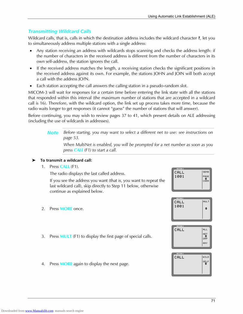
Using Automatic Link Establishment (ALE)
71
Transmitting Wildcard Calls Wildcard calls, that is, calls in which the destination address includes the wildcard character ?, let you to simultaneously address multiple stations with a single address:
• Any station receiving an address with wildcards stops scanning and checks the address length: if the number of characters in the received address is different from the number of characters in its own self-address, the station ignores the call.
• If the received address matches the length, a receiving station checks the significant positions in the received address against its own. For example, the stations JOHN and JOIN will both accept a call with the address JO?N.
• Each station accepting the call answers the calling station in a pseudo-random slot. MICOM-3 will wait for responses for a certain time before entering the link state with all the stations that responded within this interval (the maximum number of stations that are accepted in a wildcard call is 16). Therefore, with the wildcard option, the link set up process takes more time, because the radio waits longer to get responses (it cannot guess the number of stations that will answer).
Before continuing, you may wish to review pages 37 to 41, which present details on ALE addressing (including the use of wildcards in addresses).
Note Before starting, you may want to select a different net to use: see instructions on page 53.
When MultiNet is enabled, you will be prompted for a net number as soon as you press CALL (F1) to start a call.
To transmit a wildcard call:
1. Press CALL (F1).
The radio displays the last called address.
If you see the address you want (that is, you want to repeat the last wildcard call), skip directly to Step 11 below, otherwise continue as explained below.
MICOM-3
SEND
PAGE
CHAN
CALL1001
I
2. Press MORE once.
MICOM-3
MULTCALL1001
I
3. Press MULT (F1) to display the first page of special calls.
MICOM-3
ALL
NET
GRP
ANY
CALL
I
4. Press MORE again to display the next page.
MICOM-3
WILD
SELF
CALL
I
Downloaded from www.Manualslib.com manuals search engine
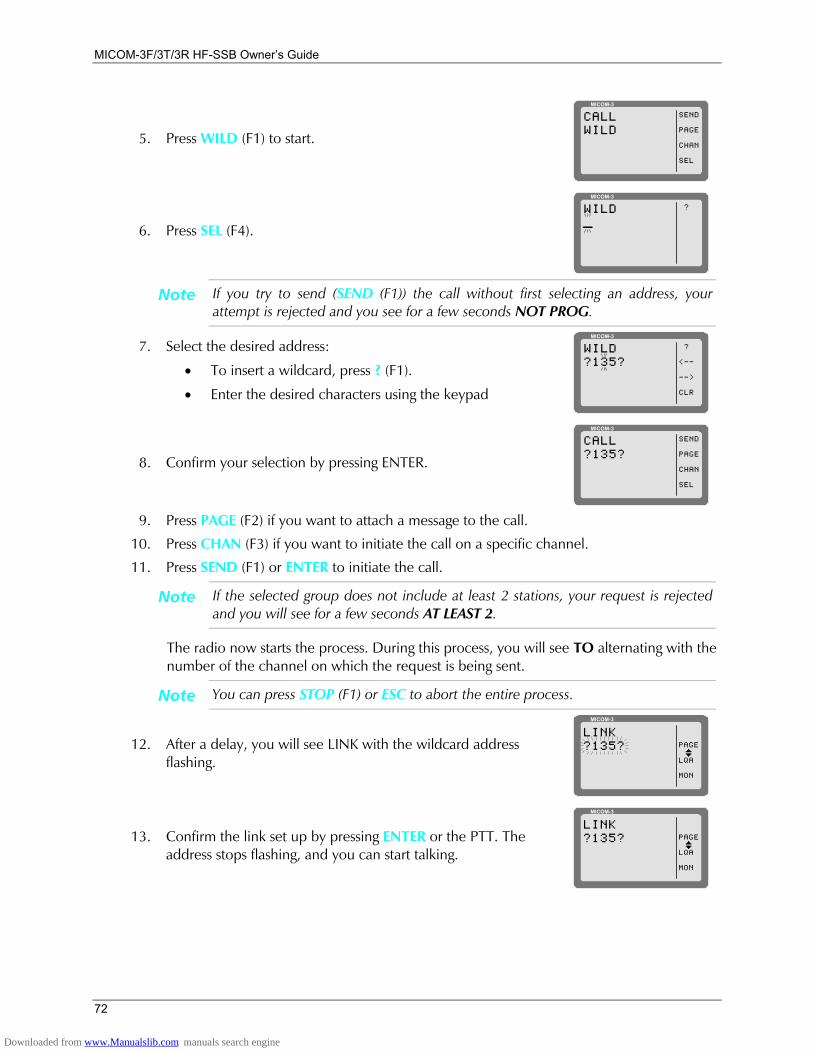
MICOM-3F/3T/3R HF-SSB Owners Guide
72
5. Press WILD (F1) to start.
MICOM-3
SEND
PAGE
CHAN
SEL
CALLWILD
6. Press SEL (F4).
MICOM-3
?WILD_
Note If you try to send (SEND (F1)) the call without first selecting an address, your attempt is rejected and you see for a few seconds NOT PROG.
7. Select the desired address:
• To insert a wildcard, press ? (F1).
• Enter the desired characters using the keypad
MICOM-3
?
<--
-->
CLR
WILD?135?
8. Confirm your selection by pressing ENTER.
MICOM-3
SEND
PAGE
CHAN
SEL
CALL?135?
9. Press PAGE (F2) if you want to attach a message to the call.
10. Press CHAN (F3) if you want to initiate the call on a specific channel.
11. Press SEND (F1) or ENTER to initiate the call.
Note If the selected group does not include at least 2 stations, your request is rejected and you will see for a few seconds AT LEAST 2.
The radio now starts the process. During this process, you will see TO alternating with the number of the channel on which the request is being sent.
Note You can press STOP (F1) or ESC to abort the entire process.
12. After a delay, you will see LINK with the wildcard address flashing.
MICOM-3
PAGE
LQA
MON
LINK?135?
I
13. Confirm the link set up by pressing ENTER or the PTT. The address stops flashing, and you can start talking.
MICOM-3
PAGE
LQA
MON
LINK?135?
I
Downloaded from www.Manualslib.com manuals search engine
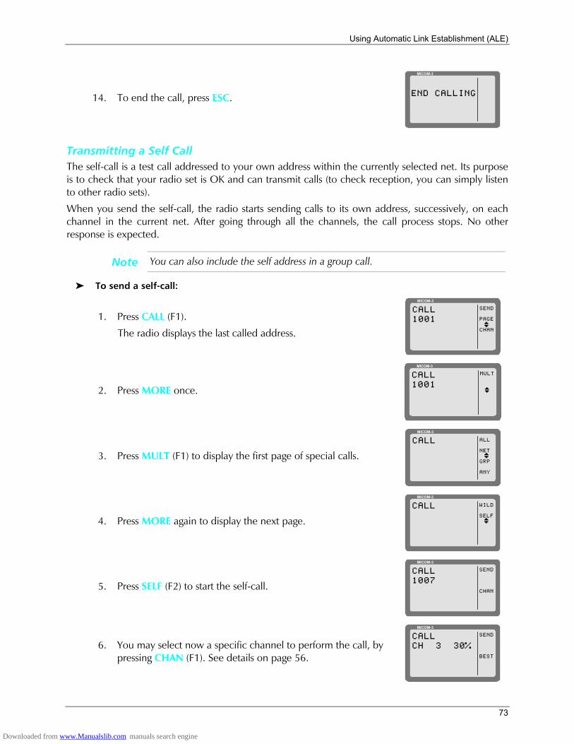
Using Automatic Link Establishment (ALE)
73
14. To end the call, press ESC.
MICOM-3
END CALLING
Transmitting a Self Call The self-call is a test call addressed to your own address within the currently selected net. Its purpose is to check that your radio set is OK and can transmit calls (to check reception, you can simply listen to other radio sets).
When you send the self-call, the radio starts sending calls to its own address, successively, on each channel in the current net. After going through all the channels, the call process stops. No other response is expected.
Note You can also include the self address in a group call.
To send a self-call:
1. Press CALL (F1).
The radio displays the last called address.
MICOM-3
SEND
PAGE
CHAN
CALL1001
I
2. Press MORE once.
MICOM-3
MULTCALL1001
I
3. Press MULT (F1) to display the first page of special calls.
MICOM-3
ALL
NET
GRP
ANY
CALL
I
4. Press MORE again to display the next page.
MICOM-3
WILD
SELF
CALL
I
5. Press SELF (F2) to start the self-call.
MICOM-3
SEND
CHAN
CALL1007
6. You may select now a specific channel to perform the call, by pressing CHAN (F1). See details on page 56.
MICOM-3
SEND
BEST
CALLCH 3 30%
Downloaded from www.Manualslib.com manuals search engine

MICOM-3F/3T/3R HF-SSB Owners Guide
74
7. When ready, press SEND (F1) to start transmitting. The display alternates between your self-address and the channel used for the call is sent. If you did not select a specific channel, the channel number changes as the radio sends the call on each channel assigned to the selected net.
After all the channels have been used, the call automatically stops.
You can press STOP (F1) at any time to end the call sooner.
MICOM-3
STOPTO1007
MICOM-3
STOPCH 31007
Bidirectional Handshake The bidirectional handshake is used to exchange LQA scores with other stations without establishing a link.
Note The MICOM-3 can also be programmed to automatically initiate the call to the station after finishing the bidirectional handshake (using the BDLK parameter reached under the ALE programming options).
A bidirectional handshake can be carried out with a single station or with all stations in the net. It can be carried out either on a single channel, or on all the net channels. When required, a message can also be added to the procedure.
After a bidirectional handshake with a single station, the LQA matrices of both radios are updated. The operator can then initiate a call to that station and obtain the best channel automatically.
When the bidirectional handshake procedure is performed with a net, all the stations in the net update their LQA tables.
MICOM-3 will wait for responses for a certain time before entering the link state with all the stations that responded within this interval (the maximum number of stations that are accepted in a bidirectional handshake is 16).
Note Before starting, you may want to select a different net to use: see instructions on page 53.
When MultiNet is enabled, you will be prompted for a net number as soon as you press CALL (F1) to start a call.
To execute a bidirectional handshake with an individual station:
1. Press LQA (F2) to enter the LQA menu.
MICOM-3
BIDR
SOND
LQA
2. Press BIDR (F1).
The last called address is displayed. If this is the address you want, skip directly to Step 6 below.
MICOM-3
SEND
PAGE
CHAN
BIDR1001
I
Downloaded from www.Manualslib.com manuals search engine

Using Automatic Link Establishment (ALE)
75
3. To select a different address, use the UP/DOWN keys to scroll to the required address in the directory, and then press ENTER to confirm your selection.
or
If the station you want to add to the group is not in the directory:
• Enter the new station using the keypad. If you make a mistake, scroll to the desired position using <-- (F2) and/or --> (F3), or clear (CLR (F4)) the whole entry and start again.
MICOM-3
SAVE
<--
-->
CLR
BIDRBU_
• When ready, press SAVE (F1) to store the new station in the directory.
MICOM-3
SEND
PAGE
CHAN
DIRBUD
I
4. Press PAGE (F2) if you wish to attach a message to the bidirectional handshake process.
After confirming the message, exclamation mark precedes the name of the called station, indicating that a message has been attached.
5. Press CHAN (F3) if you wish to execute a bidirectional handshake process on a specific channel.
6. Press SEND (F1) or ENTER in order to initiate the bidirectional handshake process. During this process, you will see TO alternating with the number of the channel on which the set up request is being sent.
Note During the bidirectional handshake process, you can press STOP (F1) or ESC to abort the entire process.
To execute a bidirectional handshake with a net:
1. Press LQA (F2) to enter the LQA menu.
MICOM-3
BIDR
SOND
LQA
2. Press BIDR (F1).
The last called address is displayed. If this is the net you want, skip directly to Step 8 below.
MICOM-3
SEND
PAGE
CHAN
BIDR1001
I
3. Press MORE.
MICOM-3
MULTBDIR1001
I
Downloaded from www.Manualslib.com manuals search engine
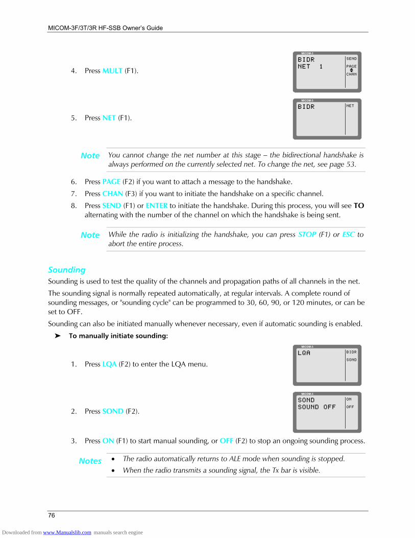
MICOM-3F/3T/3R HF-SSB Owners Guide
76
4. Press MULT (F1).
MICOM-3
SEND
PAGE
CHAN
BIDRNET 1
I
5. Press NET (F1).
MICOM-3
NETBIDR
Note You cannot change the net number at this stage the bidirectional handshake is always performed on the currently selected net. To change the net, see page 53.
6. Press PAGE (F2) if you want to attach a message to the handshake.
7. Press CHAN (F3) if you want to initiate the handshake on a specific channel.
8. Press SEND (F1) or ENTER to initiate the handshake. During this process, you will see TO alternating with the number of the channel on which the handshake is being sent.
Note While the radio is initializing the handshake, you can press STOP (F1) or ESC to abort the entire process.
Sounding Sounding is used to test the quality of the channels and propagation paths of all channels in the net.
The sounding signal is normally repeated automatically, at regular intervals. A complete round of sounding messages, or "sounding cycle" can be programmed to 30, 60, 90, or 120 minutes, or can be set to OFF.
Sounding can also be initiated manually whenever necessary, even if automatic sounding is enabled.
To manually initiate sounding:
1. Press LQA (F2) to enter the LQA menu.
MICOM-3
BIDR
SOND
LQA
2. Press SOND (F2).
MICOM-3
ON
OFF
SONDSOUND OFF
3. Press ON (F1) to start manual sounding, or OFF (F2) to stop an ongoing sounding process.
Notes • The radio automatically returns to ALE mode when sounding is stopped.
• When the radio transmits a sounding signal, the Tx bar is visible.
Downloaded from www.Manualslib.com manuals search engine
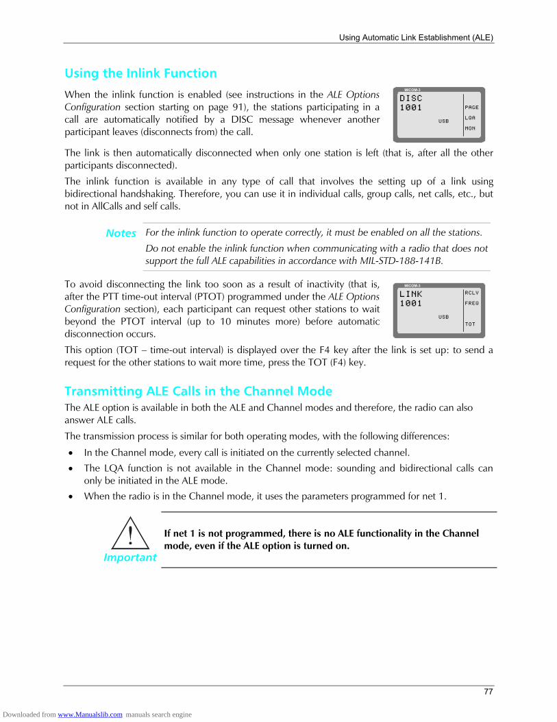
Using Automatic Link Establishment (ALE)
77
Using the Inlink Function
When the inlink function is enabled (see instructions in the ALE Options Configuration section starting on page 91), the stations participating in a call are automatically notified by a DISC message whenever another participant leaves (disconnects from) the call.
MICOM-3
PAGE
LQA
MON
DISC1001
USB
The link is then automatically disconnected when only one station is left (that is, after all the other participants disconnected).
The inlink function is available in any type of call that involves the setting up of a link using bidirectional handshaking. Therefore, you can use it in individual calls, group calls, net calls, etc., but not in AllCalls and self calls.
Notes For the inlink function to operate correctly, it must be enabled on all the stations.
Do not enable the inlink function when communicating with a radio that does not support the full ALE capabilities in accordance with MIL-STD-188-141B.
To avoid disconnecting the link too soon as a result of inactivity (that is, after the PTT time-out interval (PTOT) programmed under the ALE Options Configuration section), each participant can request other stations to wait beyond the PTOT interval (up to 10 minutes more) before automatic disconnection occurs.
MICOM-3
RCLV
FREQ
TOT
LINK1001
USB
This option (TOT time-out interval) is displayed over the F4 key after the link is set up: to send a request for the other stations to wait more time, press the TOT (F4) key.
Transmitting ALE Calls in the Channel Mode The ALE option is available in both the ALE and Channel modes and therefore, the radio can also answer ALE calls.
The transmission process is similar for both operating modes, with the following differences:
• In the Channel mode, every call is initiated on the currently selected channel.
• The LQA function is not available in the Channel mode: sounding and bidirectional calls can only be initiated in the ALE mode.
• When the radio is in the Channel mode, it uses the parameters programmed for net 1.
Important
If net 1 is not programmed, there is no ALE functionality in the Channel mode, even if the ALE option is turned on.
Downloaded from www.Manualslib.com manuals search engine
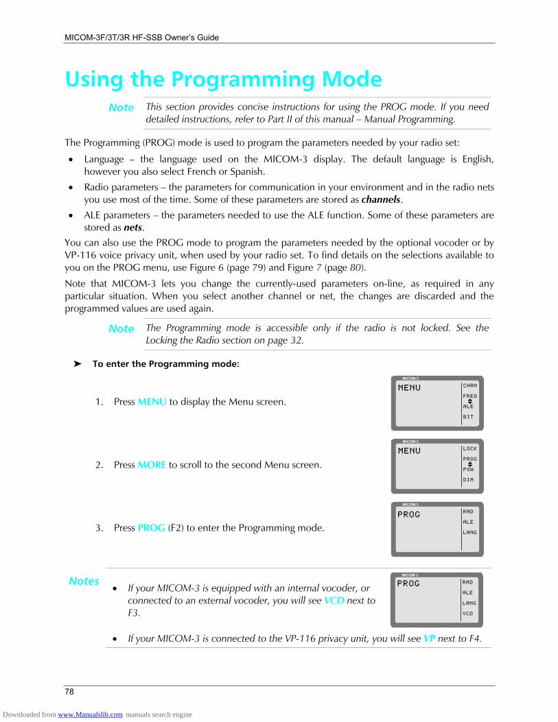
MICOM-3F/3T/3R HF-SSB Owners Guide
78
Using the Programming Mode Note This section provides concise instructions for using the PROG mode. If you need
detailed instructions, refer to Part II of this manual Manual Programming.
The Programming (PROG) mode is used to program the parameters needed by your radio set:
• Language the language used on the MICOM-3 display. The default language is English, however you also select French or Spanish.
• Radio parameters the parameters for communication in your environment and in the radio nets you use most of the time. Some of these parameters are stored as channels.
• ALE parameters the parameters needed to use the ALE function. Some of these parameters are stored as nets.
You can also use the PROG mode to program the parameters needed by the optional vocoder or by VP-116 voice privacy unit, when used by your radio set. To find details on the selections available to you on the PROG menu, use Figure 6 (page 79) and Figure 7 (page 80).
Note that MICOM-3 lets you change the currently-used parameters on-line, as required in any particular situation. When you select another channel or net, the changes are discarded and the programmed values are used again.
Note The Programming mode is accessible only if the radio is not locked. See the Locking the Radio section on page 32.
To enter the Programming mode:
1. Press MENU to display the Menu screen.
MICOM-3
CHAN
FREQ
ALE
BIT
MENU
I
2. Press MORE to scroll to the second Menu screen.
MICOM-3
LOCK
PROG
PSW
DIM
MENU
I
3. Press PROG (F2) to enter the Programming mode.
MICOM-3
RAD
ALE
LANG
PROG
• If your MICOM-3 is equipped with an internal vocoder, or connected to an external vocoder, you will see VCD next to F3.
MICOM-3
PROG RAD
ALE
LANG
VCD
Notes
• If your MICOM-3 is connected to the VP-116 privacy unit, you will see VP next to F4.
Downloaded from www.Manualslib.com manuals search engine
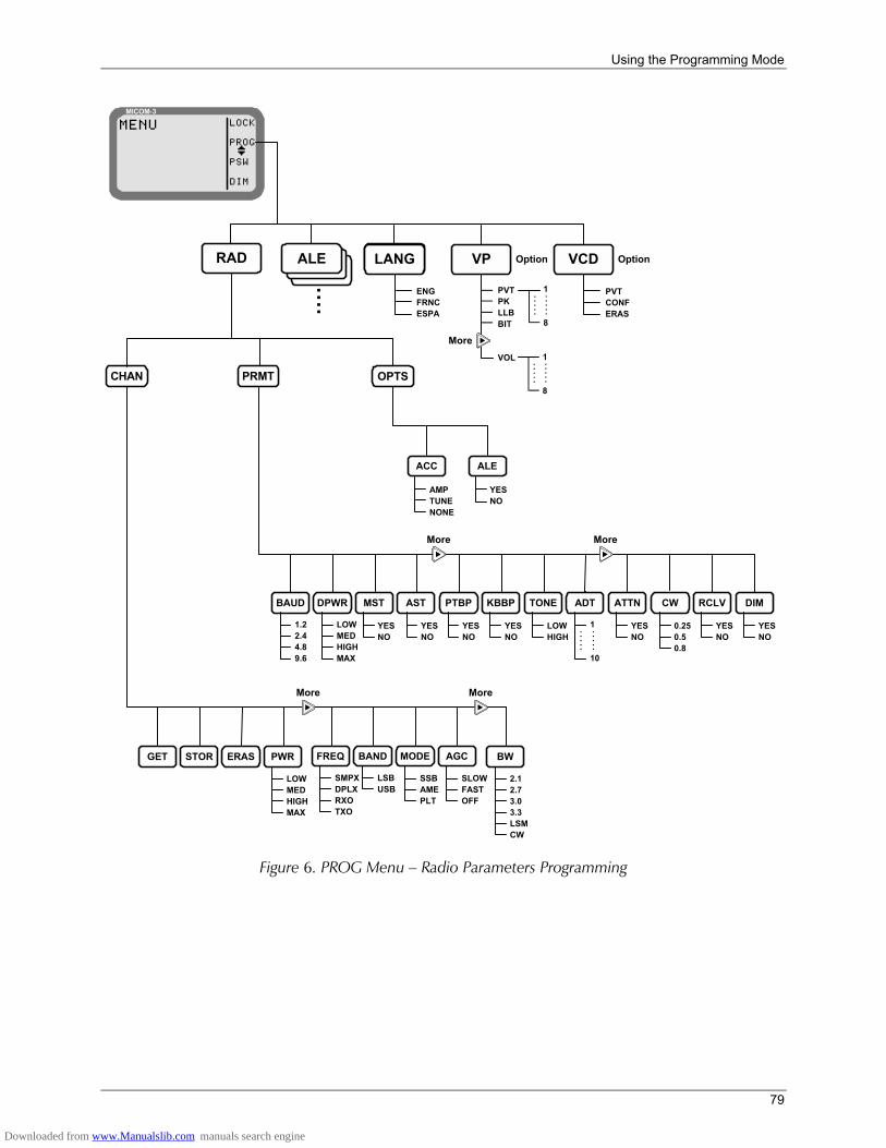
Using the Programming Mode
79
CHAN
ALERAD LANG
PRMT OPTS
YESNO
ACC ALE
AMPTUNENONE
DPWRBAUD MST AST PTBP KBBP TONE ATTNADT CW DIMRCLV
More More
MICOM-3
MENU
I
LOCK
PROG
PSW
DIM
YESNO
STORGET ERAS PWR FREQ BAND MODE BWAGC
YESNO
YESNO
YESNO
LOWHIGH
YESNO
0.250.50.8
YESNO
YESNO
LOWMEDHIGHMAX
1.22.44.89.6
LOWMEDHIGHMAX
SMPXDPLXRXOTXO
LSBUSB
SSBAMEPLT
SLOWFASTOFF
2.12.73.03.3LSMCW
MoreMore
1
10
.....
.....
....
LANG VP VCDOption Option
ENGFRNCESPA
PVTCONFERAS
More
PVTPKLLBBIT
VOL 1
8
.....
.....
1
8
.....
.....
Figure 6. PROG Menu Radio Parameters Programming
Downloaded from www.Manualslib.com manuals search engine
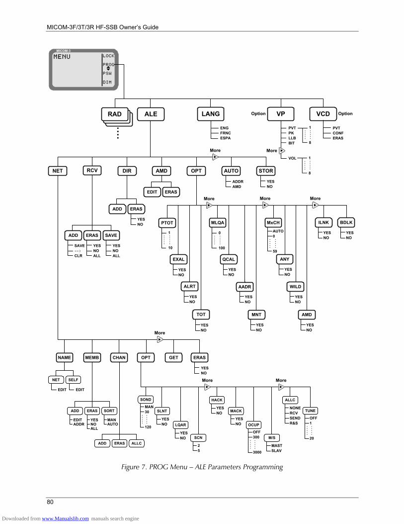
MICOM-3F/3T/3R HF-SSB Owners Guide
80
MASTSLAV
25
YESNO
MEMBNAME CHAN OPT GET ERAS
NET SELF
ADD ERAS ALLC
ADD ERAS SORT
SOND
SLNT
LQAR
SCN
HACK
MACK
OCUP
M/S
ALLC
TUNE
More
More More
YESNO
YESNO
YESNO
YESNO
MAN30
120
.....
.....
OFF300
3000
.....
.....
NONERCVSENDR&S
OFF1
20
.....
.....
EDITADDR
MANAUTO
YESNOALL
NET DIR OPT AUTO STOR
ADDRAMD
YESNO
More
YESNO
ADD ERAS
AMD
EDIT ERAS
ALE LANG
MICOM-3
MENU
I
LOCK
PROG
PSW
DIM
RAD
....
MxCH
AUTO0
59
.....
.....
More More
YESNO
EXAL
YESNO
ALRT
YESNO
TOT
MLQA
0
100
.....
.....
YESNO
QCAL
YESNO
AADR
YESNO
MNT
YESNO
ANY
YESNO
WILD
YESNO
AMD
YESNO
ILNK
More
1
10
.....
.....
PTOT
ENGFRNCESPA
RCV
ADD ERAS SAVE
YESNOALL
YESNOALL
SAVE-->
CLR
YESNO
BDLK
EDIT EDIT
VP VCD
PVTCONFERAS
Option Option
More
PVTPKLLBBIT
VOL 1
8
.....
.....
1
8
.....
.....
Figure 7. PROG Menu ALE Parameters Programming
Downloaded from www.Manualslib.com manuals search engine
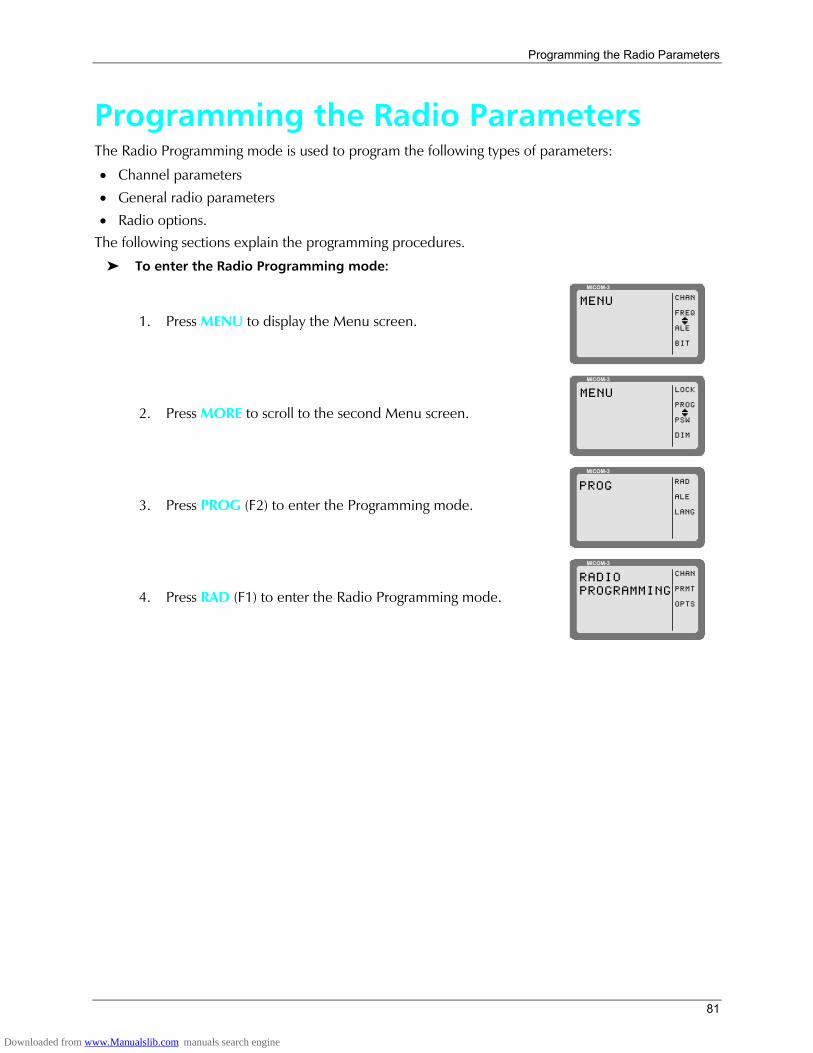
Programming the Radio Parameters
81
Programming the Radio Parameters The Radio Programming mode is used to program the following types of parameters:
• Channel parameters
• General radio parameters
• Radio options. The following sections explain the programming procedures.
To enter the Radio Programming mode:
1. Press MENU to display the Menu screen.
MICOM-3
CHAN
FREQ
ALE
BIT
MENU
I
2. Press MORE to scroll to the second Menu screen.
MICOM-3
LOCK
PROG
PSW
DIM
MENU
I
3. Press PROG (F2) to enter the Programming mode.
MICOM-3
RAD
ALE
LANG
PROG
4. Press RAD (F1) to enter the Radio Programming mode.
MICOM-3
RADIOPROGRAMMING
CHAN
PRMT
OPTS
Downloaded from www.Manualslib.com manuals search engine
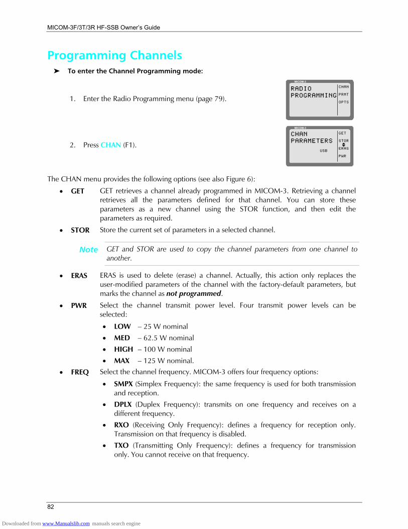
MICOM-3F/3T/3R HF-SSB Owners Guide
82
Programming Channels To enter the Channel Programming mode:
1. Enter the Radio Programming menu (page 79).
MICOM-3
RADIOPROGRAMMING
CHAN
PRMT
OPTS
2. Press CHAN (F1).
MICOM-3
GET
STOR
ERAS
PWR
CHANPARAMETERS
USBI
The CHAN menu provides the following options (see also Figure 6):
• GET GET retrieves a channel already programmed in MICOM-3. Retrieving a channel retrieves all the parameters defined for that channel. You can store these parameters as a new channel using the STOR function, and then edit the parameters as required.
• STOR Store the current set of parameters in a selected channel.
Note GET and STOR are used to copy the channel parameters from one channel to another.
• ERAS ERAS is used to delete (erase) a channel. Actually, this action only replaces the user-modified parameters of the channel with the factory-default parameters, but marks the channel as not programmed.
• PWR Select the channel transmit power level. Four transmit power levels can be selected:
• LOW 25 W nominal
• MED 62.5 W nominal
• HIGH 100 W nominal
• MAX 125 W nominal.
• FREQ Select the channel frequency. MICOM-3 offers four frequency options:
• SMPX (Simplex Frequency): the same frequency is used for both transmission and reception.
• DPLX (Duplex Frequency): transmits on one frequency and receives on a different frequency.
• RXO (Receiving Only Frequency): defines a frequency for reception only. Transmission on that frequency is disabled.
• TXO (Transmitting Only Frequency): defines a frequency for transmission only. You cannot receive on that frequency.
Downloaded from www.Manualslib.com manuals search engine
Programming the Radio Parameters
83
Note The available frequency ranges are: • Reception: 100 kHz to 30 MHz.
• Transmission: 1.6 to 30 MHz.
• BAND Select the channel SSB mode:
• USB upper sideband mode
• LSB lower sideband mode.
• MODE Select the channel radio operating mode:
• SSB single sideband
• AME amplitude modulation equivalent
• PLT single sideband with pilot signal.
• AGC Select the channel Automatic Gain Control mode. MICOM-3 offers two AGC response speeds: SLOW and FAST. You can also turn the AGC OFF completely.
• BW Select the default channel filter bandwidth:
• 2.1 K
• 2.7 K
• 3.0 K
• 3.3 K
• LSM (Low Speed Modem)
• CW (Continuous Wave). The bandwidth used in this case is selected by MENU>PROG>RAD>PRMT>CW.
Note The factory-default parameter values are as follows:
• Rx Frequency 15.000.00 MHz
• Tx Frequency 15.000.00 MHz
• SSB Mode (Band) USB
• Bandwidth 2.7K
• Tx Power MAX
• AGC Type SSB
Downloaded from www.Manualslib.com manuals search engine
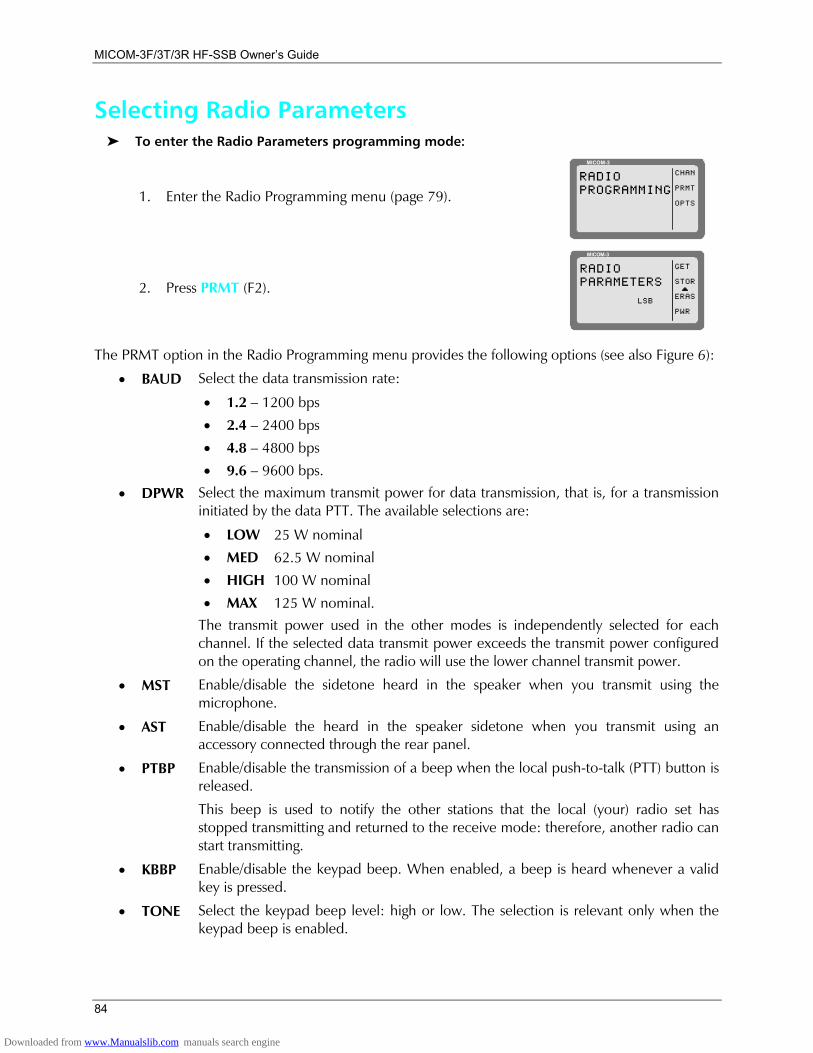
MICOM-3F/3T/3R HF-SSB Owners Guide
84
Selecting Radio Parameters To enter the Radio Parameters programming mode:
1. Enter the Radio Programming menu (page 79).
MICOM-3
RADIOPROGRAMMING
CHAN
PRMT
OPTS
2. Press PRMT (F2).
MICOM-3
GET
STOR
ERAS
PWR
RADIOPARAMETERS
LSBI
The PRMT option in the Radio Programming menu provides the following options (see also Figure 6):
• BAUD Select the data transmission rate:
• 1.2 1200 bps
• 2.4 2400 bps
• 4.8 4800 bps
• 9.6 9600 bps.
• DPWR Select the maximum transmit power for data transmission, that is, for a transmission initiated by the data PTT. The available selections are:
• LOW 25 W nominal
• MED 62.5 W nominal
• HIGH 100 W nominal
• MAX 125 W nominal. The transmit power used in the other modes is independently selected for each channel. If the selected data transmit power exceeds the transmit power configured on the operating channel, the radio will use the lower channel transmit power.
• MST Enable/disable the sidetone heard in the speaker when you transmit using the microphone.
• AST Enable/disable the heard in the speaker sidetone when you transmit using an accessory connected through the rear panel.
• PTBP Enable/disable the transmission of a beep when the local push-to-talk (PTT) button is released.
This beep is used to notify the other stations that the local (your) radio set has stopped transmitting and returned to the receive mode: therefore, another radio can start transmitting.
• KBBP Enable/disable the keypad beep. When enabled, a beep is heard whenever a valid key is pressed.
• TONE Select the keypad beep level: high or low. The selection is relevant only when the keypad beep is enabled.
Downloaded from www.Manualslib.com manuals search engine
Programming the Radio Parameters
85
• ADT Select the alternate display time-out, that is, the time after which a keypad sequence is automatically aborted in case no action is taken. In this case, the display returns to the previous screen.
The time-out interval can be selected in the range of 1 to 10 seconds.
• ATTN Enable/disable the use of the attenuator. The attenuator is used to reduce interference when your radio is located near strong transmitters.
• CW Select the channel filter bandwidth used in the CW mode:
• 0.25 250 Hz
• 0.5 500 Hz
• 0.8 800 Hz A lower value improves the reception but requires better frequency accuracy.
• RCLV Enable/disable the receive signal level display. If the receive signal indication is not enabled, you can temporarily enable it using one of the function keys.
• DIM Enable/disable automatic dimming of the display.
Usually, the display operates continuously. However, you can program the display to be normally off, and be automatically turned on when the transceiver detects any type of activity (keypad, PTT, incoming call, etc.). The ADT option selects the time before the display is again turned off when inactive.
Downloaded from www.Manualslib.com manuals search engine
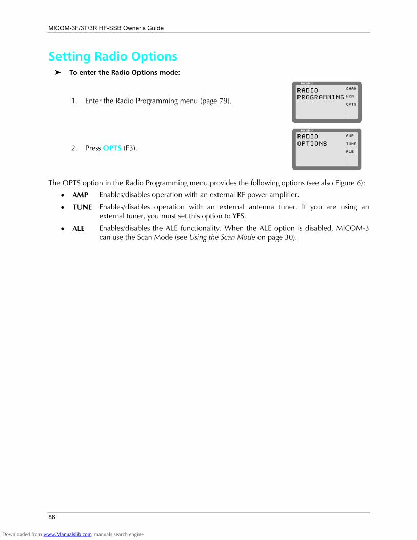
MICOM-3F/3T/3R HF-SSB Owners Guide
86
Setting Radio Options To enter the Radio Options mode:
1. Enter the Radio Programming menu (page 79).
MICOM-3
RADIOPROGRAMMING
CHAN
PRMT
OPTS
2. Press OPTS (F3).
MICOM-3
RADIOOPTIONS
AMP
TUNE
ALE
The OPTS option in the Radio Programming menu provides the following options (see also Figure 6):
• AMP Enables/disables operation with an external RF power amplifier.
• TUNE Enables/disables operation with an external antenna tuner. If you are using an external tuner, you must set this option to YES.
• ALE Enables/disables the ALE functionality. When the ALE option is disabled, MICOM-3 can use the Scan Mode (see Using the Scan Mode on page 30).
Downloaded from www.Manualslib.com manuals search engine
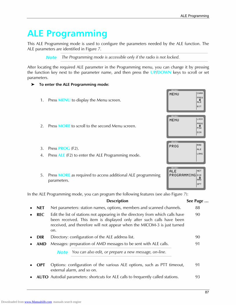
ALE Programming
87
ALE Programming This ALE Programming mode is used to configure the parameters needed by the ALE function. The ALE parameters are identified in Figure 7.
Note The Programming mode is accessible only if the radio is not locked.
After locating the required ALE parameter in the Programming menu, you can change it by pressing the function key next to the parameter name, and then press the UP/DOWN keys to scroll or set parameters.
To enter the ALE Programming mode:
1. Press MENU to display the Menu screen.
MICOM-3
CHAN
FREQ
ALE
BIT
MENU
I
2. Press MORE to scroll to the second Menu screen.
MICOM-3
LOCK
PROG
PSW
DIM
MENU
I
3. Press PROG (F2).
4. Press ALE (F2) to enter the ALE Programming mode.
MICOM-3
RAD
ALE
LANG
PROG
5. Press MORE as required to access additional ALE programming parameters.
MICOM-3
ALEPROGRAMMING
NET
DIR
AMD
OPT
I
In the ALE Programming mode, you can program the following features (see also Figure 7):
Description See Page
• NET Net parameters: station names, options, members and scanned channels. 88
• REC Edit the list of stations not appearing in the directory from which calls have been received. This item is displayed only after such calls have been received, and therefore will not appear when the MICOM-3 is just turned on.
90
• DIR Directory: configuration of the ALE address list. 90
• AMD Messages: preparation of AMD messages to be sent with ALE calls.
Note You can also edit, or prepare a new message, on-line.
91
• OPT Options: configuration of the various ALE options, such as PTT timeout, external alarm, and so on.
91
• AUTO Autodial parameters: shortcuts for ALE calls to frequently called stations. 93
Downloaded from www.Manualslib.com manuals search engine
MICOM-3F/3T/3R HF-SSB Owners Guide
88
• STOR Store the changes made in the ALE programming session. 93
The following sections explain the programming of these features. For detailed instructions, refer to Part II of this manual.
Important
• The ESC key is used to cancel a change you have made, if not yet confirmed. If you have already saved changes, the ESC key will only return to a previous screen of the ALE Programming menu.
• When you end ALE programming, you must store the parameters you defined. If you press the MENU key to exit the programming mode without first saving your changes, you will be prompted to store the ALE configuration changes. Press YES to store the configuration. If you press NO, the configuration will revert to the previous configuration, and any changes made in the current ALE programming session will be ignored.
Programming Nets When programming a net, you can set the net names, define the net members, add channels, configure various options, copy parameters from a defined net or erase an entire net.
Net Programming Overview The net programming mode enables you to view and edit the configuration of each net. The configuration includes the following menus:
• NAME Edit the net name and the self-address:
• NET: Define or edit the net names. It is not allowed to use a name already used as a self-address, nor an address already appearing in the address directory.
• SELF: Define or edit your self address (the identification of your station, to be used by other stations within the same net). It is not allowed to use a name already used as a net address, nor an address already appearing in the address directory.
A net name or self address can contain up to 15 characters. Valid characters are the letters A to Z and the numerals 0 to 9.
• MEMB Add or erase members (station addresses) from the list of net members. This list defines which stations can participate in a net call (a net can have up to 16 addresses).
The MEMB menu also enables you to sort the list of members: this determines the order in which members respond to a net call. You can arrange the order of the list of members manually, or instruct the radio to arrange them in alphanumeric order.
A member name can contain up to 15 characters. Valid characters are the letters A to Z and the numerals 0 to 9. It is not allowed to define a name already used as a net address, nor an address already appearing in the address directory. New member names will automatically be added to the directory list (unless the directory is full).
Downloaded from www.Manualslib.com manuals search engine
ALE Programming
89
• CHAN Add or remove channels to the list of scanned channels in a net, and to define the channel on which AllCalls are to be transmitted (the AllCall channel (ALLC)).
Notes • Each net can contain up to 100 scanned channels.
• All nets combined can contain up to 100 scanned channels. If you exceed this number, the message OVER 100 CH is displayed for one second, and then the display returns to the previous menu.
• If you enter a channel which is not programmed, a NOT PROG message is displayed for a second, and the display returns to the previous menu.
• OPT Configure net options, including: sounding, silent network, LQA request, scan rate, home acknowledgment, monitor acknowledgment, occupancy detection, master/slave definitions, AllCall options and tune time.
• GET Copy all parameters from one network to another. This function is useful if you are defining a new network and wish to base most of its parameters on an existing network, for instance if you need to use different frequencies/channels for day and night communication, but all other net information (such as stations and names) is identical.
• ERAS Erase an entire network from the ALE data base.
After preparing a set of parameters, your entries are checked and any errors are reported. If you do not correct the detected errors, MICOM-3 will offer to discard the new set of parameters.
Default Values Unless you define different values, each net uses the following factory-defaults:
• Net Name No default defined
• Self Address No default defined
• AllCall Send and receive enabled
• AllCall Channel No default defined
• Tune Time No tune time
• Silent No
• Home Acknowledgment Yes
• Monitor Acknowledgment No
• Master/Slave Master
• LQA Request Yes
• Sounding Manual
• Occupancy Check No
• Scanned Channels No default defined.
When programming a new network or other ALE parameters, you do not need to define all parameters change only those for which the default values are not suitable.
Downloaded from www.Manualslib.com manuals search engine
MICOM-3F/3T/3R HF-SSB Owners Guide
90
Setting the Net Options Use this menu to configure net options. The following sections explain the purpose of the net options. For detailed instructions, refer to Part II of this manual.
• SOND Sounding Parameters: define the interval (in minutes) at which automatic sounding is performed (30, 60, 90 or 120 minutes), or define sounding as a manual function. See Sounding on page 34 for a detailed explanation on the sounding process.
• SLNT Silent Mode: select whether the net is in the silent mode, which means that members in the net can initiate calls but not allowed to respond to an ALE transmission.
• LQAR LQA Reports: select whether your radio will ask the called station for a report on the quality of the communication every time a call is initiated.
• SCN Scan Rate: select the number of channels scanned each second when the radio is in ALE mode: can be set to 2 or 5 channels per second.
• HACK Home Acknowledgment: enable/disable home acknowledgment. When enabled, the radio transmits an end-of-call indication to the remote station.
• MACK Monitor Acknowledgment: enable/disable monitor acknowledgment. When enabled, the radio transmits an accept call indication to the station that initiated the call.
• OCUP Occupancy Check: enable/disable the occupancy check. The occupancy check defines whether the radio uses the speech detect mechanism to determine whether a channel on which a call is about to be made is occupied. If this option is ON, a call cannot be initiated on a channel determined to be occupied. This option can be operated in addition to the ALE signal detection mechanism.
You can select the interval at which occupancy checks are made (300 to 3000 msec, in 300-msec increments).
• M/S Master/Slave: select whether your radio serves as a master or slave in the current ALE network. Only a master station can initiate a Net Call.
• ALLC AIICall Settings: this option determines whether the ALE is able to receive and/or send AllCalls. An AIICall is an ALE broadcast transmission. All stations receiving an AIICall are linked to the sender, even if they do not recognize the senders address. If no AIICall channel is defined, the call will be made on the best channel in the net.
• TUNE Tune Time: select the tuning time. Tuning time is the maximum time the current ALE waits for the called station to tune (this is the tune-in time of the slowest tuner in the net). The tune time is added to the calculated response time. Tune time can be 1 to 20 seconds, or OFF (zero).
Directory Parameters This DIR option on the ALE Programming menu enables preparing the ALE address list. This list contains the names of stations to which the radio can address a private call using the ALE. You can add a new address, and edit an existing address.
A name can contain up to 15 characters. Valid characters are the letters A to Z and the numerals 0 to 9. You cannot add an address which is identical to the name of a programmed net, nor an address already used as a self address in a programmed net. The list can contain up to 100 addresses, and is automatically sorted in ascending alphanumeric order.
Downloaded from www.Manualslib.com manuals search engine
ALE Programming
91
AMD Message Configuration The AMD option of the ALE Programming menu is used to view, edit, add or erase messages intended for transmission. The characters you can enter in messages using the radio keypad are: A to Z, 0 to 9, space, * and #. See message preparation details on page 59.
Messages programmed using a remote PC with a standard keyboard can contain all the ASCII characters the range of 20 (hex) to 5F (hex).
The message list can contain up to 12 messages, numbered AMD 0 to AMD 11. Each message can contain up to 90 characters.
Note If no messages are stored, empty will appear in the second display line.
ALE Options Configuration This menu enables you to configure the following ALE options:
• PTOT PTT Timeout: the time (in minutes) which elapses between the moment you release the PTT button, until the ALE disconnects the link. The allowed range is 1 to 10 minutes.
• EXAL External Alarm: activate/deactivate the radio external alarm when a call is received.
• ALRT Alert tone: enable/disable the generation of an alert tone whenever a link is established.
• TOT Accept Link Time-out Time: the radio can be configured to disconnect the link automatically if neither the PTT, nor any other key is pressed within 30 seconds from the reception of a call. If Accept Link TOT is set to NO, the received call is accepted immediately and automatically.
• MLQA Minimum LQA Score: determines the minimum acceptable LQA (Link Quality Analysis) score allowed when trying to establish a link on a specific channel.
If the minimum score is not achieved when the radio attempts to establish a link in the ALE mode, the radio will try to establish a link on the scanned channel with the next best LQA score. At the end of this process, a link will be established on the scan channel with the best LQA score. If the call is made on a specific channel, the radio ignores the minimum LQA score check.
The allowed range of LQA scores is 0 to 100%. When selecting the minimum LQA score, remember that in accordance with the ALE standards, the maximum LQA score (assigned for receiving an optimum sounding is 70%), and the minimum score is 30%. The score given to a station that did not send any sounding or a station whose sounding has not been received is also 30%.
• QCAL Quick Call: enable/disable initiating a call to the last called address by pressing the MIC PTT button twice in rapid sequence (double pressing).
• AADR Automatic address: enable/disable automatically adding the source addresses of incoming calls to the ALE directory.
Note If the directory is full, new addresses will not be added.
Downloaded from www.Manualslib.com manuals search engine
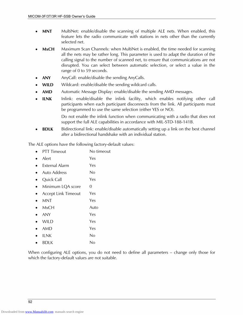
MICOM-3F/3T/3R HF-SSB Owners Guide
92
• MNT MultiNet: enable/disable the scanning of multiple ALE nets. When enabled, this feature lets the radio communicate with stations in nets other than the currently selected net.
• MxCH Maximum Scan Channels: when MultiNet is enabled, the time needed for scanning all the nets may be rather long. This parameter is used to adapt the duration of the calling signal to the number of scanned net, to ensure that communications are not disrupted. You can select between automatic selection, or select a value in the range of 0 to 59 seconds.
• ANY AnyCall: enable/disable the sending AnyCalls.
• WILD Wildcard: enable/disable the sending wildcard calls.
• AMD Automatic Message Display: enable/disable the sending AMD messages.
• ILNK Inlink: enable/disable the inlink facility, which enables notifying other call participants when each participant disconnects from the link. All participants must be programmed to use the same selection (either YES or NO).
Do not enable the inlink function when communicating with a radio that does not support the full ALE capabilities in accordance with MIL-STD-188-141B.
• BDLK Bidirectional link: enable/disable automatically setting up a link on the best channel after a bidirectional handshake with an individual station.
The ALE options have the following factory-default values:
• PTT Timeout No timeout
• Alert Yes
• External Alarm Yes
• Auto Address No
• Quick Call Yes
• Minimum LQA score 0
• Accept Link Timeout Yes • MNT Yes • MxCH Auto • ANY Yes • WILD Yes • AMD Yes • ILNK No • BDLK No
When configuring ALE options, you do not need to define all parameters change only those for which the factory-default values are not suitable.
Downloaded from www.Manualslib.com manuals search engine
ALE Programming
93
Auto Dial Parameters Auto Dial enables you to set shortcuts for calls to frequently called stations, with or without automatically attaching messages when a station is called:
• AUTO Used to configure up to 10 autodial codes, numbered AUTO 0 to AUTO 9. • AMD Used to prepare AMD messages for sending when an autodial code is used. See
message preparation details on page 59.
Note If a message is attached to the address, an exclamation mark precedes the address.
Storing ALE parameters Before exiting the ALE programming menu, you must store the parameters you have programmed.
Important
If you press the MENU or ESC key to exit programming mode without first saving your changes, you will be prompted to store the ALE configuration changes. Press YES to store the configuration.
If you press NO, the configuration will revert to the previous configuration, and any changes made in the ALE programming session will be ignored.
Downloaded from www.Manualslib.com manuals search engine
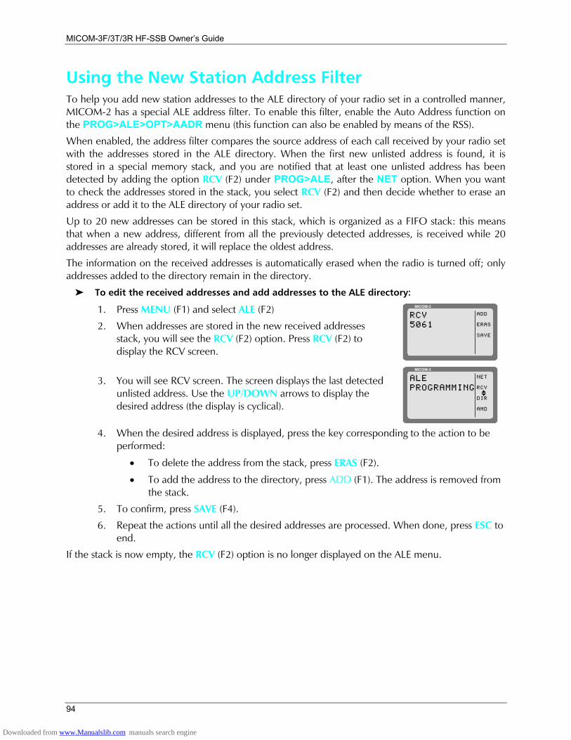
MICOM-3F/3T/3R HF-SSB Owners Guide
94
Using the New Station Address Filter To help you add new station addresses to the ALE directory of your radio set in a controlled manner, MICOM-2 has a special ALE address filter. To enable this filter, enable the Auto Address function on the PROG>ALE>OPT>AADR menu (this function can also be enabled by means of the RSS).
When enabled, the address filter compares the source address of each call received by your radio set with the addresses stored in the ALE directory. When the first new unlisted address is found, it is stored in a special memory stack, and you are notified that at least one unlisted address has been detected by adding the option RCV (F2) under PROG>ALE, after the NET option. When you want to check the addresses stored in the stack, you select RCV (F2) and then decide whether to erase an address or add it to the ALE directory of your radio set.
Up to 20 new addresses can be stored in this stack, which is organized as a FIFO stack: this means that when a new address, different from all the previously detected addresses, is received while 20 addresses are already stored, it will replace the oldest address.
The information on the received addresses is automatically erased when the radio is turned off; only addresses added to the directory remain in the directory.
To edit the received addresses and add addresses to the ALE directory:
1. Press MENU (F1) and select ALE (F2)
2. When addresses are stored in the new received addresses stack, you will see the RCV (F2) option. Press RCV (F2) to display the RCV screen.
MICOM-3
ADD
ERAS
SAVE
RCV5061
3. You will see RCV screen. The screen displays the last detected unlisted address. Use the UP/DOWN arrows to display the desired address (the display is cyclical).
MICOM-3
NET
RCV
DIR
AMD
ALEPROGRAMMING
I
4. When the desired address is displayed, press the key corresponding to the action to be
performed:
• To delete the address from the stack, press ERAS (F2).
• To add the address to the directory, press ADD (F1). The address is removed from the stack.
5. To confirm, press SAVE (F4).
6. Repeat the actions until all the desired addresses are processed. When done, press ESC to end.
If the stack is now empty, the RCV (F2) option is no longer displayed on the ALE menu.
Downloaded from www.Manualslib.com manuals search engine
Using the VP-116 Mini Voice Privacy Unit
95
Using the VP-116 Mini Voice Privacy Unit
Introduction The VP-116 Voice Privacy unit provides voice privacy at good voice quality. For information on the VP-116 unit, read the manual supplied with the unit.
You can order option G849 that enables the MICOM-3 to support the VP software, so that you can program the VP-116 unit directly from the radio.
Notes The VP menu appears on your MICOM-3 radio only if the radio is connected to the VP-116 before the radio is turned on.
Radio performance may be reduced when a VP unit is connected.
Specific Parameters for Privacy Operation When the radio is turned while the VP-116 is physically connected to the MICOM-3, the radio automatically starts using the specific parameters needed by the VP-116. For example, you can see that when the privacy function is used, the bandwidth is set to 3.3K, instead of 2.7K in the clear mode (operation without VP).
After you turn the radio off and disconnect the VP-116, the radio reverts to normal operation with a 2.7K filter bandwidth.
The parameter values used by the VP-116 are as follows:
• Volume: Level 6
• Squelch: Level 0
• Sidetone: Level 0.
• Squelch: OFF
• BW: 3.3K filter.
Connecting/Disconnecting the VP-116 Unit To connect the VP-116 to your MICOM-3:
1. Turn the radio off.
2. Connect the VP-116 to the 44-pin accessories connector at the back panel of your MICOM-3, using the supplied cable.
3. Turn the radio on.
To disconnect the VP-116 from your MICOM-3:
Important
If you do not turn the radio off before disconnecting the VP-116, the radio will continue working in the VP-116 mode, even though the unit is disconnected.
Downloaded from www.Manualslib.com manuals search engine

MICOM-3F/3T/3R HF-SSB Owners Guide
96
4. Turn the radio off.
5. Disconnect the VP-116 from the 44-pin accessories connector of your MICOM-3.
6. Turn the radio on.
Using the VP-116 Unit When operating the radio with the VP-116 unit in the Channel, Frequency or ALE mode, you can choose between the CLR and PVT (private) modes:
• PVT activates the VP-116 automatic voice privacy functions
• CLR reverts to regular radio activity.
Notes 1. There are eight preprogrammed PVT keys, PVT1 to PVT8, and one public key (PK). Program the key to be used as described in the Programming the VP-116 Unit from the MICOM-3 section starting on page 97. The currently-used key number appears on the screen.
2. In the PVT and PK modes, the VP controls whether you hear or not the received signals, and therefore the squelch option (SQ (F3)) is not displayed. The Squelch option (F3) appears only in the Clear (CLR) mode.
3. When the PTT is activated, a hold-off tone sounds. Wait for the hold-off tone to end before talking.
To use the VP-116 unit in the Channel mode:
1. Press PVT# (F1) whenever it is necessary to toggle between the PVT (Private) and CLR (Clear) modes.
MICOM-3
CLR
BAND
SQ
DSP
CH 6F 16,000.00
USBI
BW3.3K
Note When using the public key, you see PK (F1) instead of PVT#.
MICOM-3
PVT3
BAND
DSP
CH 6F 16,000.00
USBI
BW3.3K
To use the VP-116 unit in the Frequency mode:
1. When using the Frequency mode, press MORE twice to access the third screen.
MICOM-3
RCLV
STOR
VP
FREQF 16,000.00
USBI
BW3.3K
2. Press PVT# (F3) whenever it is necessary to toggle between the PVT (Private) and CLR
(Clear) modes.
To use the VP-116 unit in the ALE mode:
1. Enable the ALE mode, as described in Enabling the ALE Mode on page 43.
2. After a link has been set up, press PVT# (F1) whenever it is necessary to toggle between the PVT (Private) and CLR (Clear) modes.
Downloaded from www.Manualslib.com manuals search engine
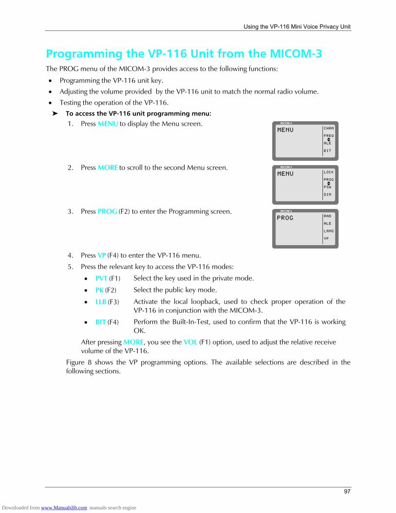
Using the VP-116 Mini Voice Privacy Unit
97
Programming the VP-116 Unit from the MICOM-3 The PROG menu of the MICOM-3 provides access to the following functions:
• Programming the VP-116 unit key.
• Adjusting the volume provided by the VP-116 unit to match the normal radio volume.
• Testing the operation of the VP-116. To access the VP-116 unit programming menu:
1. Press MENU to display the Menu screen. MICOM-3
CHAN
FREQ
ALE
BIT
MENU
I
2. Press MORE to scroll to the second Menu screen. MICOM-3
LOCK
PROG
PSW
DIM
MENU
I
3. Press PROG (F2) to enter the Programming screen. MICOM-3
RAD
ALE
LANG
VP
PROG
4. Press VP (F4) to enter the VP-116 menu. 5. Press the relevant key to access the VP-116 modes:
• PVT (F1) Select the key used in the private mode.
• PK (F2) Select the public key mode.
• LLB (F3) Activate the local loopback, used to check proper operation of the VP-116 in conjunction with the MICOM-3.
• BIT (F4) Perform the Built-In-Test, used to confirm that the VP-116 is working OK.
After pressing MORE, you see the VOL (F1) option, used to adjust the relative receive volume of the VP-116.
Figure 8 shows the VP programming options. The available selections are described in the following sections.
Downloaded from www.Manualslib.com manuals search engine
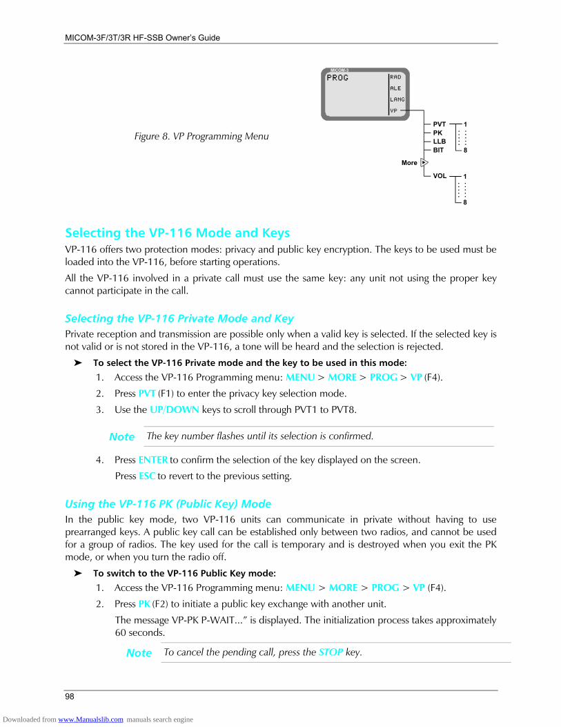
MICOM-3F/3T/3R HF-SSB Owners Guide
98
Figure 8. VP Programming Menu
MICOM-3RAD
ALE
LANG
VP
PROG
More
PVTPKLLBBIT
VOL 1
8
.....
.....
1
8
.....
.....
Selecting the VP-116 Mode and Keys VP-116 offers two protection modes: privacy and public key encryption. The keys to be used must be loaded into the VP-116, before starting operations.
All the VP-116 involved in a private call must use the same key: any unit not using the proper key cannot participate in the call.
Selecting the VP-116 Private Mode and Key Private reception and transmission are possible only when a valid key is selected. If the selected key is not valid or is not stored in the VP-116, a tone will be heard and the selection is rejected.
To select the VP-116 Private mode and the key to be used in this mode:
1. Access the VP-116 Programming menu: MENU > MORE > PROG > VP (F4).
2. Press PVT (F1) to enter the privacy key selection mode.
3. Use the UP/DOWN keys to scroll through PVT1 to PVT8.
Note The key number flashes until its selection is confirmed.
4. Press ENTER to confirm the selection of the key displayed on the screen.
Press ESC to revert to the previous setting.
Using the VP-116 PK (Public Key) Mode In the public key mode, two VP-116 units can communicate in private without having to use prearranged keys. A public key call can be established only between two radios, and cannot be used for a group of radios. The key used for the call is temporary and is destroyed when you exit the PK mode, or when you turn the radio off.
To switch to the VP-116 Public Key mode:
1. Access the VP-116 Programming menu: MENU > MORE > PROG > VP (F4).
2. Press PK (F2) to initiate a public key exchange with another unit.
The message VP-PK P-WAIT... is displayed. The initialization process takes approximately 60 seconds.
Note To cancel the pending call, press the STOP key.
Downloaded from www.Manualslib.com manuals search engine
Using the VP-116 Mini Voice Privacy Unit
99
When the other unit responds, you will see PVT-P.
3. Press PTT to start talking in the PK mode.
To cancel the call, both parties must press ESC.
If after 120 seconds there is no response from the other station, or the radio identifies a communication error, the message ERR RESPONSE is displayed.
Press STOP (F1) to end the call.
To respond to a VP-116 public key call:
When a public key call is sent to you, the message VP-PK P-WAIT is displayed on your radio.
• Press RESP (F2) to answer the PK request.
• Press STOP (F1) to cancel the PK request. After approximately 60 seconds, the message PVT-P is displayed:
• Press PTT to start talking in the PK mode.
• Press ESC to cancel the call.
VP-116 LLB (Local Loopback) Mode The Local Loopback (LLB) mode tests the local audio circuits by closing a loopback from the microphone input to the speaker output; this loopback remains connected until the ESC key is pressed.
Note No signal is actually transmitted by the radio.
To perform the VP-116 Local Loopback test:
1. Access the VP-116 Programming menu: MENU > MORE > PROG > VP (F4).
2. Press LLB (F3) to enter the LLB mode.
3. Press the PTT and talk. When everything is OK, you will hear your own signal during the test.
4. Press ESC to end the LLB test.
VP-116 BIT (Built-In-Test) Mode The BIT mode enables checking the proper operation of the VP-116 unit.
To perform the VP-116 Built-In-Test:
1. Access the VP-116 Programming menu: MENU > MORE > PROG > VP (F4).
2. Press BIT (F4) to start the BIT test.
3. During the test, the message IN TEST... is displayed. The number of periods indicates the progress of the test.
• If the test is successful, VP BIT-PASS is displayed.
• A malfunction is detected in the VP-116, you will see VP BIT-ERR. In this case, repeat the BIT test. If the test fails again, your VP-116 must be serviced.
4. Press ESC to end the BIT mode.
Downloaded from www.Manualslib.com manuals search engine
MICOM-3F/3T/3R HF-SSB Owners Guide
100
Using the Vocoder
Introduction A vocoder option can be ordered for the MICOM-3. The vocoder provides voice privacy at good voice quality, using digital signal processing techniques.
The vocoder supports the following protection modes:
• Privacy (PVT) mode, compatible with the VP-116 Mini Voice Privacy Unit. The vocoder can store up to 8 private keys for use in this mode.
• Digital (DIG) encryption mode. You can select the desired protection mode, or switch to the clear (CLR) mode. To support protected communication, the radio bandwidth is automatically switched to 3.3K.
The vocoder can be used in all the modes (Channel, Frequency and ALE).
Note When using the DIG mode with ALE, the radio scans in the Clear mode. When a vocoder call is detected, the radio automatically switches to the protected DIG mode after the link is established, and returns to scan in the Clear mode after the link is disconnected.
Using the Vocoder When operating the radio with the vocoder in the Channel, Frequency or ALE mode, you can choose between the CLR, DIG, and PVT (private) modes:
• PVT activates the automatic voice privacy functions
• DIG activates the vocoder digital encryption function
• CLR reverts to regular radio activity.
Notes 1. There are eight preprogrammed PVT keys, PVT1 to PVT8, and one digital encryption key (DIG). Program the key to be used as described in the Programming the Vocoder section starting on page 102. The currently-used key number appears on the screen.
2. In the PVT and DIG modes, the vocoder controls whether you hear or not the received signals, and therefore the squelch option (SQ (F3)) is not displayed. The Squelch option (F3) appears only in the Clear (CLR) mode.
3. When the PTT is activated, a hold-off tone sounds. Wait for the hold-off tone to end before talking.
Downloaded from www.Manualslib.com manuals search engine
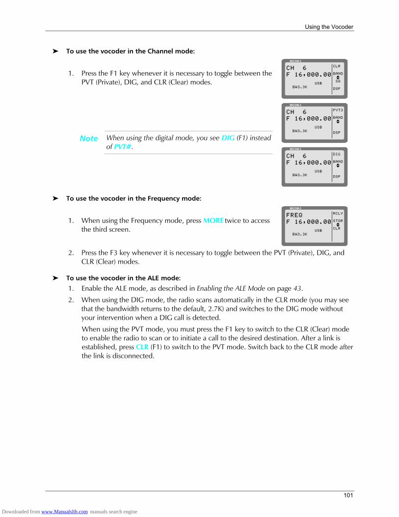
Using the Vocoder
101
To use the vocoder in the Channel mode:
1. Press the F1 key whenever it is necessary to toggle between the PVT (Private), DIG, and CLR (Clear) modes.
MICOM-3
CLR
BAND
SQ
DSP
CH 6F 16,000.00
USBI
BW3.3K
Note When using the digital mode, you see DIG (F1) instead of PVT#.
MICOM-3
PVT3
BAND
DSP
CH 6F 16,000.00
USBI
BW3.3K
MICOM-3
DIG
BAND
DSP
CH 6F 16,000.00
USBI
BW3.3K
To use the vocoder in the Frequency mode:
1. When using the Frequency mode, press MORE twice to access the third screen.
MICOM-3
RCLV
STOR
CLR
FREQF 16,000.00
USBI
BW3.3K
2. Press the F3 key whenever it is necessary to toggle between the PVT (Private), DIG, and
CLR (Clear) modes.
To use the vocoder in the ALE mode:
1. Enable the ALE mode, as described in Enabling the ALE Mode on page 43.
2. When using the DIG mode, the radio scans automatically in the CLR mode (you may see that the bandwidth returns to the default, 2.7K) and switches to the DIG mode without your intervention when a DIG call is detected.
When using the PVT mode, you must press the F1 key to switch to the CLR (Clear) mode to enable the radio to scan or to initiate a call to the desired destination. After a link is established, press CLR (F1) to switch to the PVT mode. Switch back to the CLR mode after the link is disconnected.
Downloaded from www.Manualslib.com manuals search engine
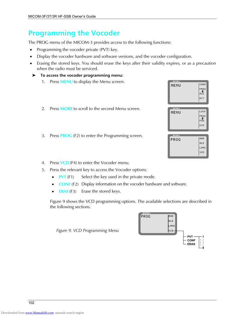
MICOM-3F/3T/3R HF-SSB Owners Guide
102
Programming the Vocoder The PROG menu of the MICOM-3 provides access to the following functions:
• Programming the vocoder private (PVT) key.
• Display the vocoder hardware and software versions, and the vocoder configuration.
• Erasing the stored keys. You should erase the keys after their validity expires, or as a precaution when the radio must be serviced.
To access the vocoder programming menu:
1. Press MENU to display the Menu screen. MICOM-3
CHAN
FREQ
ALE
BIT
MENU
I
2. Press MORE to scroll to the second Menu screen. MICOM-3
LOCK
PROG
PSW
DIM
MENU
I
3. Press PROG (F2) to enter the Programming screen. MICOM-3
RAD
ALE
LANG
VCD
PROG
4. Press VCD (F4) to enter the Vocoder menu. 5. Press the relevant key to access the Vocoder options:
• PVT (F1) Select the key used in the private mode.
• CONF (F2) Display information on the vocoder hardware and software.
• ERAS (F3) Erase the stored keys.
Figure 9 shows the VCD programming options. The available selections are described in the following sections.
Figure 9. VCD Programming Menu
MICOM-3RAD
ALE
LANG
VCD
PROG
PVTCONFERAS
1
8
.....
.....
Downloaded from www.Manualslib.com manuals search engine
Using the Vocoder
103
Selecting the Vocoder Mode and Keys Vocoder offers two protection modes: privacy and public key encryption. The keys to be used must be loaded into the vocoder, before starting operations.
Selecting the Vocoder Private Key Private reception and transmission are possible only when a valid key is selected. If the selected key is not valid or is not stored in the vocoder, a tone will be heard and the selection is rejected.
To select the vocoder private key to be used in this mode:
1. Access the Vocoder Programming menu: MENU > MORE > PROG > VCD (F4).
2. Press PVT (F1) to enter the privacy key selection mode.
3. Use the UP/DOWN keys to scroll through PVT1 to PVT8.
Note The displayed key number flashes until its selection is confirmed.
4. Press ENTER to confirm the selection of the key displayed on the screen.
Press ESC to revert to the previous setting.
Display of Vocoder Information 1. Access the Vocoder Programming menu: MENU > MORE > PROG > VCD (F4).
2. Press CONF (F2).
3. The screen changes to display the vocoder host version, and the function of key F1 changes: it now enables you to scroll cyclically through the information items displayed on the screen.
Note If you need additional details on the displayed information, contact [email protected].
4. To end the display, press ESC.
Erasing the Stored Keys 1. Access the Vocoder Programming menu: MENU > MORE > PROG > VCD (F4).
2. Press ERAS (F3).
3. You are requested to confirm: press YES (F1), or cancel the task by pressing NO (F2).
Downloaded from www.Manualslib.com manuals search engine

MICOM-3F/3T/3R HF-SSB Owners Guide
104
Using the MICOM-3 GPS Receiver
Introduction This section provides you with the information needed to use the GPS receiver option.
Note MICOM-3 transceivers that support the internal GPS receiver option have a connector for the GPS antenna on their rear cover. The GPS receiver itself is installed only upon specific order.
GPS Receiver Functions The GPS receiver is an integral part of the MICOM-3 transceiver and can be used whenever the GPS antenna supplied together with the MICOM-3 transceiver is properly connected and installed.
The GPS receiver provides accurate time and navigation data. The navigation data includes the geographical coordinates (position data) and the altitude. When the MICOM-3 transceiver is moving, you can also see the speed and direction (heading).
The information collected by the GPS receiver can be displayed on the MICOM-3 display when using the CH and FREQ modes. In the ALE mode, the position data can be reported by means of AMD messages; it can also be automatically reported in response to position queries (also sent by AMD messages).
Format of GPS Information The format of the navigation data can be selected in accordance with your needs:
• LLA format: Latitude, longitude and altitude (LLA). The latitude and longitude are displayed in degrees, with a precision of hundredths of arc minutes (1/100 min); the altitude is reported in meters, relative to the mean sea level (MSL). Velocity is reported as the change in the East, North, and Up coordinates, presented in meter/sec with a precision of 0.001 meter/sec.
• ECEF format: Earth-Centered, Earth-Fixed format for position and velocity. Provides your position and velocity in a Cartesian (X, Y, Z) coordinate frame with its center at the Earth's center, the Z-axis through the North Pole, and the X-axis through 0 degrees longitude, 0 degrees latitude. The position is reported in meters. Velocity for each axis (that is, is the change in the X, Y and Z coordinate) is displayed in meter/sec, with a precision up to 0.001 meter/sec.
The time is always presented on basis of the UTC (Universal Time Coordinated).
How to Get the Best Results from your MICOM-3 GPS Receiver The GPS receiver extracts the information it needs by analyzing the signals received from GPS satellites. These satellite periodically transmit navigation messages, where the transmission of each complete message requires almost 15 minutes. To calculate all the data your GPS receiver is capable of providing, it must receive and decode navigation messages from at least 4 GPS satellites (the GPS receiver can use as many as 8 satellites to improve accuracy).
Downloaded from www.Manualslib.com manuals search engine
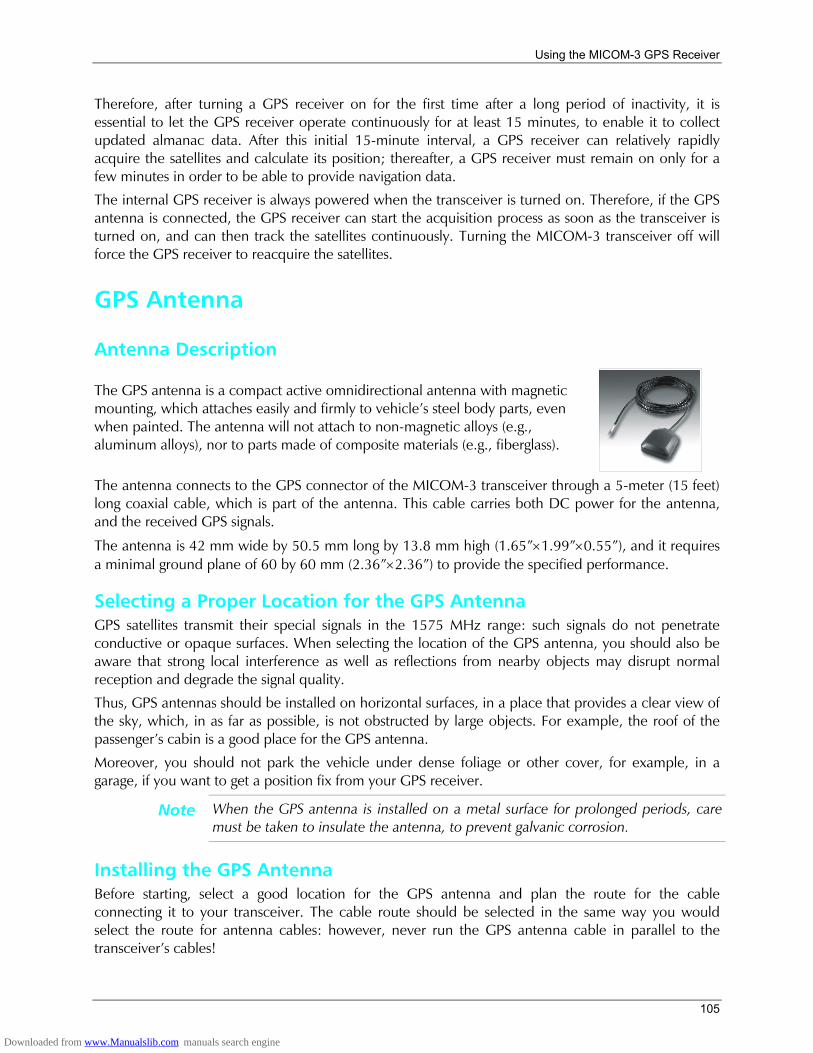
Using the MICOM-3 GPS Receiver
105
Therefore, after turning a GPS receiver on for the first time after a long period of inactivity, it is essential to let the GPS receiver operate continuously for at least 15 minutes, to enable it to collect updated almanac data. After this initial 15-minute interval, a GPS receiver can relatively rapidly acquire the satellites and calculate its position; thereafter, a GPS receiver must remain on only for a few minutes in order to be able to provide navigation data.
The internal GPS receiver is always powered when the transceiver is turned on. Therefore, if the GPS antenna is connected, the GPS receiver can start the acquisition process as soon as the transceiver is turned on, and can then track the satellites continuously. Turning the MICOM-3 transceiver off will force the GPS receiver to reacquire the satellites.
GPS Antenna
Antenna Description
The GPS antenna is a compact active omnidirectional antenna with magnetic mounting, which attaches easily and firmly to vehicles steel body parts, even when painted. The antenna will not attach to non-magnetic alloys (e.g., aluminum alloys), nor to parts made of composite materials (e.g., fiberglass).
The antenna connects to the GPS connector of the MICOM-3 transceiver through a 5-meter (15 feet) long coaxial cable, which is part of the antenna. This cable carries both DC power for the antenna, and the received GPS signals.
The antenna is 42 mm wide by 50.5 mm long by 13.8 mm high (1.65×1.99×0.55), and it requires a minimal ground plane of 60 by 60 mm (2.36×2.36) to provide the specified performance.
Selecting a Proper Location for the GPS Antenna GPS satellites transmit their special signals in the 1575 MHz range: such signals do not penetrate conductive or opaque surfaces. When selecting the location of the GPS antenna, you should also be aware that strong local interference as well as reflections from nearby objects may disrupt normal reception and degrade the signal quality.
Thus, GPS antennas should be installed on horizontal surfaces, in a place that provides a clear view of the sky, which, in as far as possible, is not obstructed by large objects. For example, the roof of the passengers cabin is a good place for the GPS antenna.
Moreover, you should not park the vehicle under dense foliage or other cover, for example, in a garage, if you want to get a position fix from your GPS receiver.
Note When the GPS antenna is installed on a metal surface for prolonged periods, care must be taken to insulate the antenna, to prevent galvanic corrosion.
Installing the GPS Antenna Before starting, select a good location for the GPS antenna and plan the route for the cable connecting it to your transceiver. The cable route should be selected in the same way you would select the route for antenna cables: however, never run the GPS antenna cable in parallel to the transceivers cables!
Downloaded from www.Manualslib.com manuals search engine
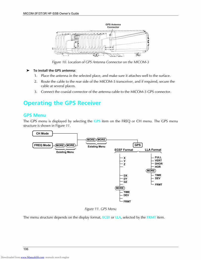
MICOM-3F/3T/3R HF-SSB Owners Guide
106
GPS AntennaConnector
Figure 10. Location of GPS Antenna Connector on the MICOM-3
To install the GPS antenna:
1. Place the antenna in the selected place, and make sure it attaches well to the surface.
2. Route the cable to the rear side of the MICOM-3 transceiver, and if required, secure the cable at several places.
3. Connect the coaxial connector of the antenna cable to the MICOM-3 GPS connector.
Operating the GPS Receiver
GPS Menu The GPS menu is displayed by selecting the GPS item on the FREQ or CH menu. The GPS menu structure is shown in Figure 11.
CH Mode
FREQ Mode Existing MenuMORE
Existing Menu
MORE
MORE MORE
GPSLLA FormatECEF Format
FULLVERTDHORHOR
TIMEDEV
FRMT
XYZ
DXDYDZ
TIMEDEV
FRMT
MORE
MORE
Figure 11. GPS Menu
The menu structure depends on the display format, ECEF or LLA, selected by the FRMT item.
Downloaded from www.Manualslib.com manuals search engine
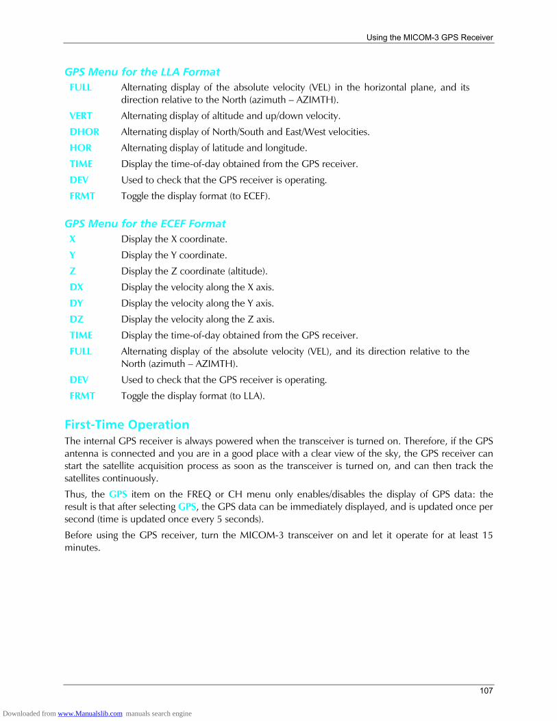
Using the MICOM-3 GPS Receiver
107
GPS Menu for the LLA Format FULL Alternating display of the absolute velocity (VEL) in the horizontal plane, and its
direction relative to the North (azimuth AZIMTH).
VERT Alternating display of altitude and up/down velocity.
DHOR Alternating display of North/South and East/West velocities.
HOR Alternating display of latitude and longitude.
TIME Display the time-of-day obtained from the GPS receiver.
DEV Used to check that the GPS receiver is operating.
FRMT Toggle the display format (to ECEF).
GPS Menu for the ECEF Format X Display the X coordinate.
Y Display the Y coordinate.
Z Display the Z coordinate (altitude).
DX Display the velocity along the X axis.
DY Display the velocity along the Y axis.
DZ Display the velocity along the Z axis.
TIME Display the time-of-day obtained from the GPS receiver.
FULL Alternating display of the absolute velocity (VEL), and its direction relative to the North (azimuth AZIMTH).
DEV Used to check that the GPS receiver is operating.
FRMT Toggle the display format (to LLA).
First-Time Operation The internal GPS receiver is always powered when the transceiver is turned on. Therefore, if the GPS antenna is connected and you are in a good place with a clear view of the sky, the GPS receiver can start the satellite acquisition process as soon as the transceiver is turned on, and can then track the satellites continuously.
Thus, the GPS item on the FREQ or CH menu only enables/disables the display of GPS data: the result is that after selecting GPS, the GPS data can be immediately displayed, and is updated once per second (time is updated once every 5 seconds).
Before using the GPS receiver, turn the MICOM-3 transceiver on and let it operate for at least 15 minutes.
Downloaded from www.Manualslib.com manuals search engine
MICOM-3F/3T/3R HF-SSB Owners Guide
108
Operating Instructions
Switching to the GPS Display
Note You cannot switch to the GPS display if you are using the ALE mode.
1. Select the GPS item by scrolling with the MORE key on the FREQ or CH menu, and then pressing F2. You will see a message that indicates the current display format, GPS LLA or GPS ECEF.
2. If necessary, switch to the alternate display format: press MORE as required to see FRMT, and then press the key next to FRMT (F4).
3. If the GPS receiver operates normally and is ready, you will see the information selected the last time the receiver has been used.
Selecting what to Display 1. Press the key next to the type of information you want to see: use Figure 11 to find the key.
2. The displayed information appears on the display and is automatically updated every second. The time is updated every 5 seconds.
3. To change the display of GPS information, scroll to the desired item.
4. To cancel the display of GPS information, select any other menu except GPS.
Sending Your Position/GPS Position Requests You can use the ALE AMD service to:
1. Send your position to any another destination (including one-to-many).
2. Request the position of another MICOM-3 transceiver equipped with the optional GPS receiver. You can make this type of request only when you call an individual station:
• If the request is made in the CALL mode (that is, before a link has been set up between the two stations), a link will be set up and then the other station will automatically return an AMD message with its latitude and longitude.
• If the request is made while in the LINK mode, the other station displays WHERE ARE YOU?. In this case, the operator can manually send its position as explained below.
Note that the operations described above automatically set up a link between the two stations and therefore it is necessary to disconnect the link when it is no longer needed. For this purpose, it is recommended to enable HOME acknowledge, and/or enable the PTT time-out function.
Note AMD messages with the GPS position do not enter the stack (the information such message carries is good only at the time you got it): if you do not read the message in time, you can no longer retrieve the message at a later time.
Thus, you must allow sufficient time for the destination station to read the position message before when link is disconnected. This is particularly important when HOME acknowledge is enabled: the message will disappear as soon as you disconnect the link.
Downloaded from www.Manualslib.com manuals search engine
Using the MICOM-3 GPS Receiver
109
To send your position report to other station(s):
1. Select the CALL mode (either from the ALE mode or the CHAN mode).
2. Select the destination address and/or the call type.
3. Select the PAGE selection mode.
4. Scroll until you see the I AM AT message, and then send the message.
5. Your station sends the AMD message with your latitude and longitude.
To automatically get the position of another station:
1. Select the CALL mode (either from the ALE mode or the CHAN mode).
2. Select the destination address (you can make only an individual call).
3. Select the PAGE selection mode.
4. Scroll until you see the RMT POS message, and then send the message.
5. Your station starts the link set up to the selected station; after the link is set up, you will see the response AMD of the called station, which includes its latitude and longitude.
6. You may now continue with voice communication, or disconnect the link to the called station.
To send a position request to the station you are linked to:
1. While in the LINK mode, select the PAGE selection mode.
2. Scroll until you see the RMT POS message, and then send the message.
3. The called station displays WHERE ARE YOU?:
• To send an automatic response, the called operator select the PAGE selection mode, and then sends the I AM AT message as explained above.
• Alternatively, the called operator may answer with a voice message.
What to do if 1. If the GPS display mode, GPS LLA or GPS ECEF, does not appear when switching to the GPS
display, scroll to the DEV item. You should see the GPS receiver type.
• If you see UNKNOWN, turn the MICOM-3 transceiver off and after a few minutes turn it back on. If the problem persists, the GPS receiver must be serviced.
• If you see NONE, your MICOM-3 transceiver does not include the optional GPS receiver.
2. If the requested information does not appear within 15 minutes, but the check in Step 1 above is successful, check for proper connection of the GPS antenna cable to the rear GPS antenna connector of the transceiver.
3. After checking that the antenna is properly connected, check that the GPS antenna did not shift from its intended position, and has a clear view of the sky. Try to improve your location: avoid locations near trees, high buildings, or steep hills.
Downloaded from www.Manualslib.com manuals search engine
MICOM-3F/3T/3R HF-SSB Owners Guide
110
Installation
General This section describes the installation of the radio in a mobile or fixed station configuration.
The following paragraphs contain general installation procedures for both types of configuration.
Government Regulations Read carefully the Licensing and Safety Information given in the front matter of this manual. Be sure that all your radio operations comply with these guidelines.
Inspection Carefully inspect the radio immediately upon receipt, and notify the shipper of any damage incurred in transit.
Radio Installation Planning Select the mounting location for convenience of access to electrical connections and for maintenance. The selected location should be clean, dry and well ventilated. Do not mount the unit in close proximity to strong electrical fields produced by brush motors and generators, welders, etc.
The antenna, antenna tuner and associated cable kits are provided separately. These should be installed before the radio is installed. Follow the instructions included with the units and kits.
The radio may be placed on any sturdy, flat surface. An accessory mounting tray (included in the Mobile Mounting Kit, FLN2272) allows the radio to be mounted in any position.
Before installing the radio, read the entire installation procedure detailed in this section. Follow the instructions carefully.
No preliminary internal wiring connections are required before installing the radio.
Downloaded from www.Manualslib.com manuals search engine
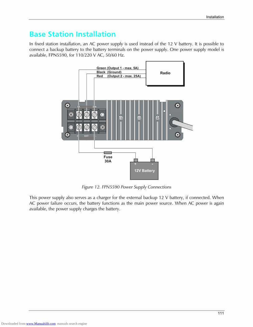
Installation
111
Base Station Installation In fixed station installation, an AC power supply is used instead of the 12 V battery. It is possible to connect a backup battery to the battery terminals on the power supply. One power supply model is available, FPN5590, for 110/220 V AC, 50/60 Hz.
12V Battery
Fuse30A
Green (Output 1 - max. 5A)Black (Ground)Red (Output 2 - max. 25A)
Radio
5A GND 25A5A - 25A
Figure 12. FPN5590 Power Supply Connections
This power supply also serves as a charger for the external backup 12 V battery, if connected. When AC power failure occurs, the battery functions as the main power source. When AC power is again available, the power supply charges the battery.
Downloaded from www.Manualslib.com manuals search engine
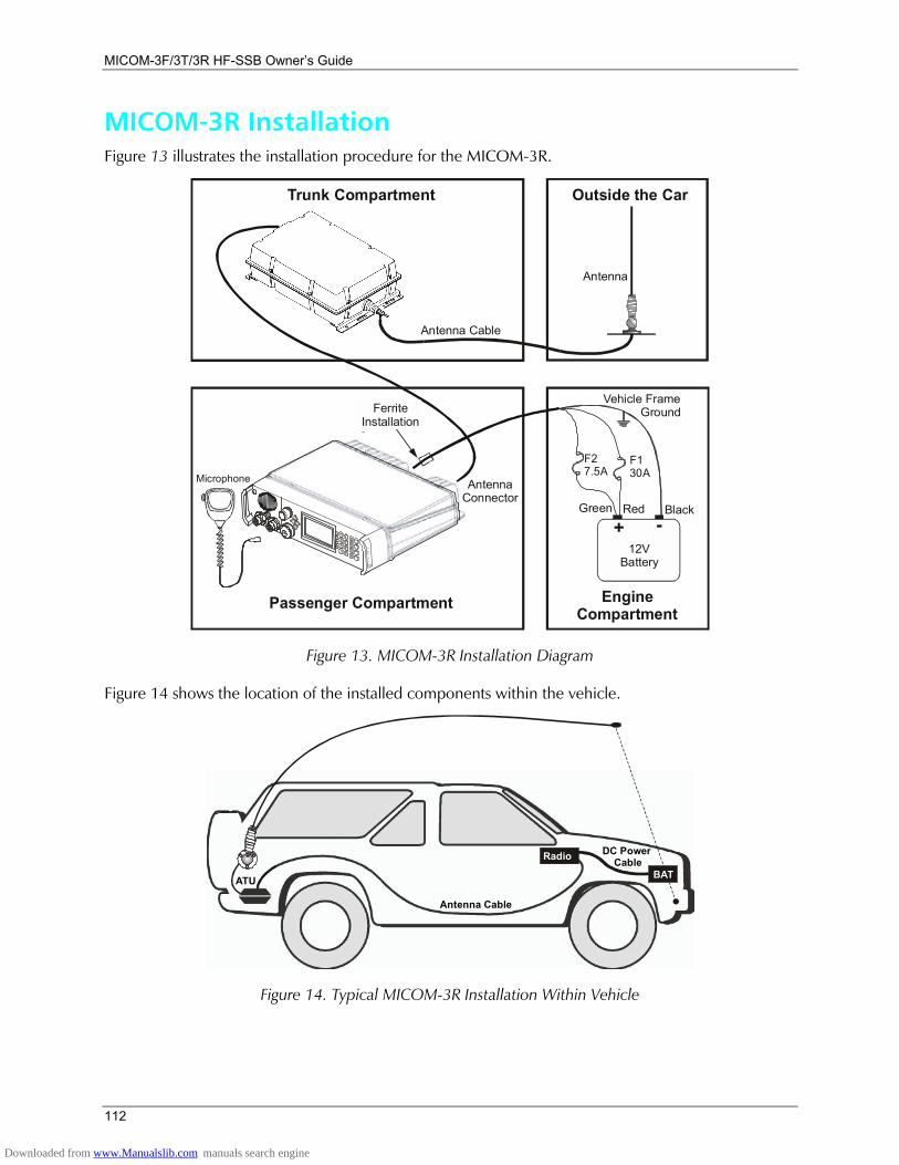
MICOM-3F/3T/3R HF-SSB Owners Guide
112
MICOM-3R Installation Figure 13 illustrates the installation procedure for the MICOM-3R.
+ -
F130A
Antenna Cable
Green Red Black
Vehicle Frame Ground
12VBattery
F27.5A
Trunk Compartment
Passenger Compartment Engine Compartment
Outside the Car
Antenna
FerriteInstallation
AntennaConnector
Microphone
Figure 13. MICOM-3R Installation Diagram
Figure 14 shows the location of the installed components within the vehicle.
Radio
ATU
Antenna Cable
DC Power Cable
BAT
Figure 14. Typical MICOM-3R Installation Within Vehicle
Downloaded from www.Manualslib.com manuals search engine

Installation
113
The radio is installed on the dashboard of the vehicle inside the passenger compartment. The other components connect to the power source, the battery, and to the antenna, which enables the radio to transmit and receive.
If the battery is located in the rear section of the vehicle, the power cable extends to the battery location in the rear.
Note To achieve maximum operating range, the antenna should be mounted as high on the vehicle body as possible without striking overhead obstructions in the normal service area of the vehicle. Select a mounting location on a flat portion of the vehicle body, compatible with the maximum allowable high voltage lead-in cable length.
MICOM-3F Installation The procedure shown above for the MICOM-3R is also used to install the MICOM-3F.
MICOM-3T Installation For MICOM-3T, only the control head, the speaker, and the microphone are installed in the passenger compartment of the vehicle. The radio transceiver is installed in the trunk of the vehicle together with the antenna tuner.
Figure 15 illustrates the installation procedure for the MICOM-3T.
FerriteInstallation
FerriteInstallation
Antenna Connector
Antenna Cable
Power Cable Control Head Cable
Control Head
PowerConnector
Transceiver
Trunk Compartment
Passenger Compartment
Outside the Car
Antenna
Green Red Black
Vehicle FrameGround
EngineCompartment
+ -12V
Battery
F27.5A
F130A
MicrophoneSpeaker
SpeakerConnector
AntennaTuner
Figure 15. MICOM-3T Installation Diagram
Downloaded from www.Manualslib.com manuals search engine

MICOM-3F/3T/3R HF-SSB Owners Guide
114
Figure 16 shows the location of the installed components within the vehicle.
ATU
DC Power Cable
BAT
ControlHead
RadioRadio
1
2Control Head
Cable
Figure 16. Typical MICOM-3T Installation Within Vehicle
The MICOM-3T model requires the connection of two cables across the length of the vehicle because the radio transceiver is located in the trunk. If the battery is located in the rear section of the vehicle, the power cable extends to the battery location.
Notes 1. The upper installation (number 1 in Figure 16), is recommended over the front installation (number 2 in Figure 16) because of the covering that protects the control head from direct sunlight.
2. To achieve maximum operating range, the antenna should be mounted as high on the vehicle body as possible without striking overhead obstructions in the normal service area of the vehicle. Select a mounting location on a flat portion of the vehicle body, compatible with the maximum allowable high voltage lead-in cable length.
Downloaded from www.Manualslib.com manuals search engine
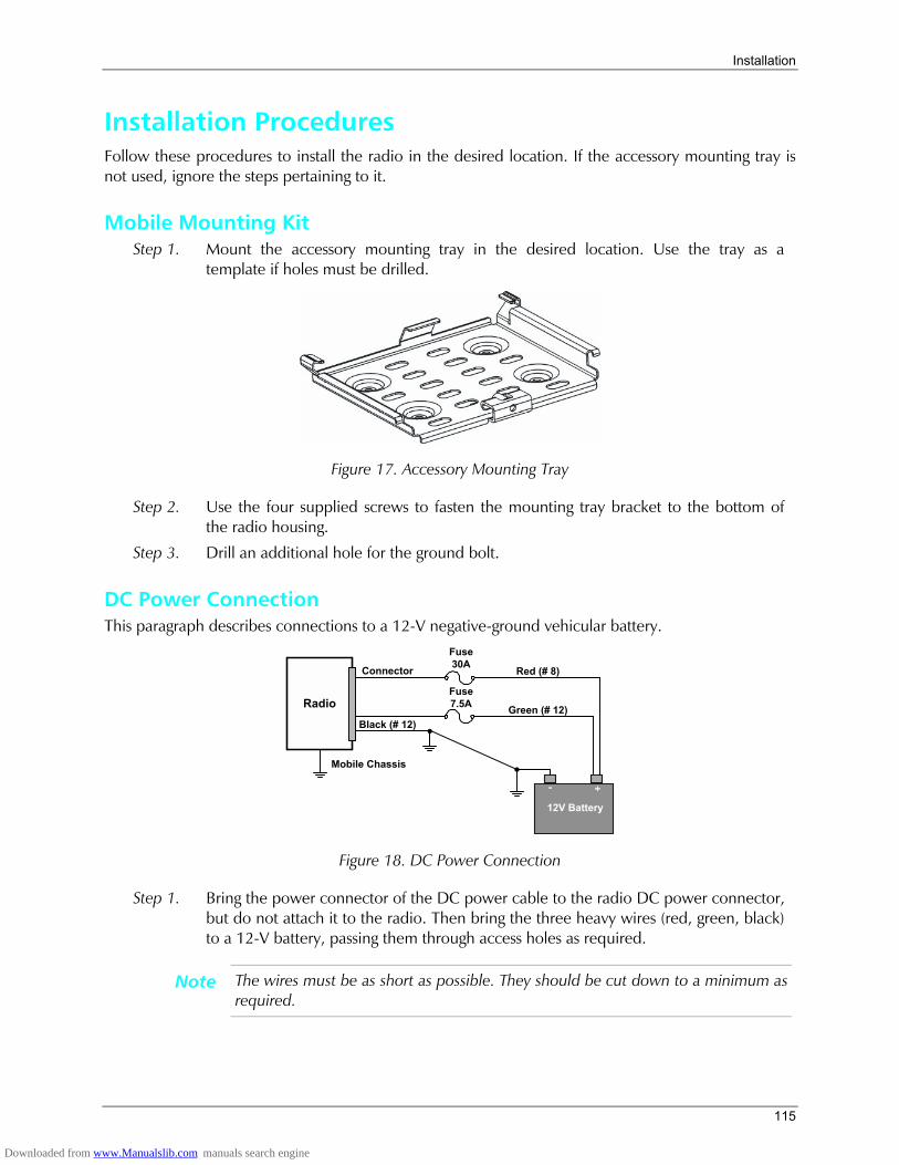
Installation
115
Installation Procedures Follow these procedures to install the radio in the desired location. If the accessory mounting tray is not used, ignore the steps pertaining to it.
Mobile Mounting Kit Step 1. Mount the accessory mounting tray in the desired location. Use the tray as a
template if holes must be drilled.
Figure 17. Accessory Mounting Tray
Step 2. Use the four supplied screws to fasten the mounting tray bracket to the bottom of the radio housing.
Step 3. Drill an additional hole for the ground bolt.
DC Power Connection This paragraph describes connections to a 12-V negative-ground vehicular battery.
12V Battery
Radio Green (# 12)
Red (# 8)
Black (# 12)
Fuse30A
Fuse7.5A
Connector
Mobile Chassis
Figure 18. DC Power Connection
Step 1. Bring the power connector of the DC power cable to the radio DC power connector, but do not attach it to the radio. Then bring the three heavy wires (red, green, black) to a 12-V battery, passing them through access holes as required.
Note The wires must be as short as possible. They should be cut down to a minimum as required.
Downloaded from www.Manualslib.com manuals search engine
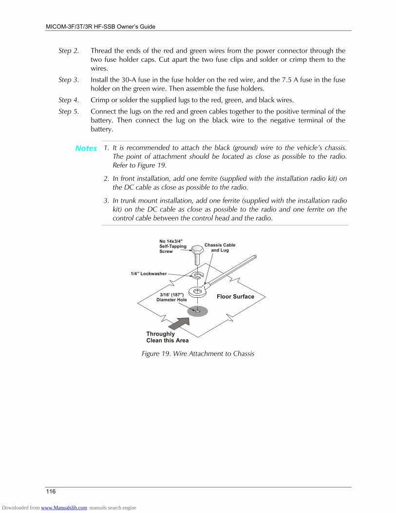
MICOM-3F/3T/3R HF-SSB Owners Guide
116
Step 2. Thread the ends of the red and green wires from the power connector through the two fuse holder caps. Cut apart the two fuse clips and solder or crimp them to the wires.
Step 3. Install the 30-A fuse in the fuse holder on the red wire, and the 7.5 A fuse in the fuse holder on the green wire. Then assemble the fuse holders.
Step 4. Crimp or solder the supplied lugs to the red, green, and black wires.
Step 5. Connect the lugs on the red and green cables together to the positive terminal of the battery. Then connect the lug on the black wire to the negative terminal of the battery.
Notes 1. It is recommended to attach the black (ground) wire to the vehicles chassis. The point of attachment should be located as close as possible to the radio. Refer to Figure 19.
2. In front installation, add one ferrite (supplied with the installation radio kit) on the DC cable as close as possible to the radio.
3. In trunk mount installation, add one ferrite (supplied with the installation radio kit) on the DC cable as close as possible to the radio and one ferrite on the control cable between the control head and the radio.
1/4 Lockwasher
ThroughlyClean this Area
Chassis Cableand Lug
Floor Surface
No 14x3/4"Self-TappingScrew
3/16' (187")Diameter Hole
Figure 19. Wire Attachment to Chassis
Downloaded from www.Manualslib.com manuals search engine
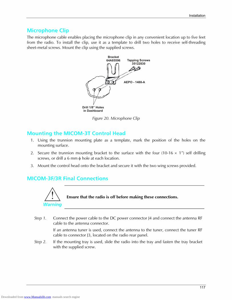
Installation
117
Microphone Clip The microphone cable enables placing the microphone clip in any convenient location up to five feet from the radio. To install the clip, use it as a template to drill two holes to receive self-threading sheet-metal screws. Mount the clip using the supplied screws.
Drill 1/8 Holesin Dashboard
Tapping Screws35122830
AEPO - 1488-A
Bracket64A85596
Figure 20. Microphone Clip
Mounting the MICOM-3T Control Head 1. Using the trunnion mounting plate as a template, mark the position of the holes on the
mounting surface.
2. Secure the trunnion mounting bracket to the surface with the four (10-16 × 1) self drilling screws, or drill a 6 mm φ hole at each location.
3. Mount the control head onto the bracket and secure it with the two wing screws provided.
MICOM-3F/3R Final Connections
Warning
Ensure that the radio is off before making these connections.
Step 1. Connect the power cable to the DC power connector J4 and connect the antenna RF cable to the antenna connector.
If an antenna tuner is used, connect the antenna to the tuner, connect the tuner RF cable to connector J3, located on the radio rear panel.
Step 2. If the mounting tray is used, slide the radio into the tray and fasten the tray bracket with the supplied screw.
Downloaded from www.Manualslib.com manuals search engine

MICOM-3F/3T/3R HF-SSB Owners Guide
118
Figure 21. Fitting Radio onto Mounting Tray
Step 3. Use the tie straps included with Cable Kit to tie loose cables out of the way.
Step 4. Connect a ground lead from the GND screw on the radio body to the mobile chassis.
Important
Special attention should be given to locating a good vehicle ground. Optimum radio performance can only be achieved with a ground connection having a very low resistance. The vehicle frame makes the best ground, but body structural reinforcement members are also suitable for grounding purposes. The ground lead should be as short as possible.
Step 5. If desired, plug an external speaker into the accessories connector. Any speaker with an impedance greater than 8 ohms can be used.
External Speaker Installation for MICOM-3F Connect the external speaker (8Ω, 8W) to the accessories connector (pins 1, 3). The external speaker is connected in parallel to the internal speaker.
To disconnect the internal speaker, perform the following steps:
Step 1. Insert a small, flat-blade screwdriver in the slotted area on the right hand-side panel of the radio and press the screwdriver towards you, to release the control head.
Figure 22. Opening the MICOM-3F Control Head
Step 2. Disconnect the internal speaker from the board.
Downloaded from www.Manualslib.com manuals search engine

Installation
119
Step 3. Return the top cover to its original position by applying pressure on both sides of the cover. Observe that the seal is correctly located.
MICOM-3T Final Connections
Warning
Ensure that the radio is off before making these connections.
1. Connect the power cable to DC power connector and connect the antenna RF cable to the antenna connector.
In an antenna tuner is used, connect the antenna to the tuner, connect the tuner RF cable to the RF connector located on the radio rear panel.
2. If a mounting tray is used, slide the radio with bracket into the tray and fasten the bracket to the tray with the supplied screw (see Figure 21 on page 118).
3. Use the tie straps included with the cable kit to tie loose cables out of the way.
4. Connect a ground lead from the GND screw on the radio body to the chassis of the vehicle.
5. Connect the control head cable to the connector in the front panel of the radio and to control head.
Important
Special attention should be given to locating a good vehicle ground. Optimum radio performance can only be achieved with a ground connection having a very low resistance.
The vehicle frame makes the best ground, but body structural reinforcement members are also suitable for grounding purposes.
The ground lead should be as short as possible.
Operational Checks When installation is complete, carefully check all operating functions (refer to the Operation section). In case of malfunctioning, refer to Troubleshooting section in this manual.
Downloaded from www.Manualslib.com manuals search engine
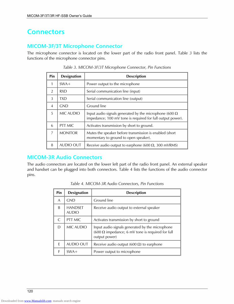
MICOM-3F/3T/3R HF-SSB Owners Guide
120
Connectors
MICOM-3F/3T Microphone Connector The microphone connector is located on the lower part of the radio front panel. Table 3 lists the functions of the microphone connector pins.
Table 3. MICOM-3F/3T Microphone Connector, Pin Functions
Pin Designation Description
1 SWA+ Power output to the microphone
2 RXD Serial communication line (input)
3 TXD Serial communication line (output)
4 GND Ground line
5 MIC AUDIO Input audio signals generated by the microphone (600 Ω impedance; 100 mV tone is required for full output power).
6 PTT MIC Activates transmission by short to ground.
7 MONITOR Mutes the speaker before transmission is enabled (short momentary to ground to open speaker).
8 AUDIO OUT Receive audio output to earphone (600 Ω, 300 mVRMS)
MICOM-3R Audio Connectors The audio connectors are located on the lower left part of the radio front panel. An external speaker and handset can be plugged into both connectors. Table 4 lists the functions of the audio connector pins.
Table 4. MICOM-3R Audio Connectors, Pin Functions
Pin Designation Description
A GND Ground line
B HANDSET AUDIO
Receive audio output to external speaker
C PTT MIC Activates transmission by short to ground
D MIC AUDIO Input audio signals generated by the microphone (600 Ω impedance; 6 mV tone is required for full output power)
E AUDIO OUT Receive audio output (600 Ω) to earphone
F SWA+ Power output to microphone
Downloaded from www.Manualslib.com manuals search engine
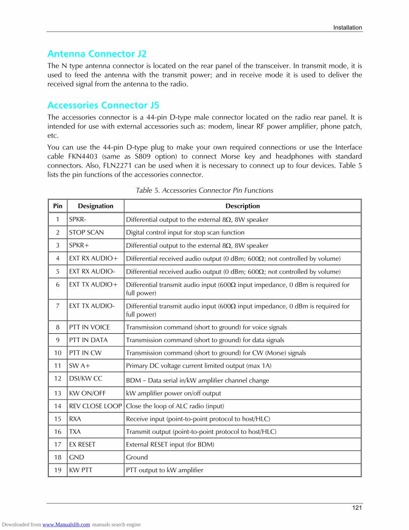
Installation
121
Antenna Connector J2 The N type antenna connector is located on the rear panel of the transceiver. In transmit mode, it is used to feed the antenna with the transmit power; and in receive mode it is used to deliver the received signal from the antenna to the radio.
Accessories Connector J5 The accessories connector is a 44-pin D-type male connector located on the radio rear panel. It is intended for use with external accessories such as: modem, linear RF power amplifier, phone patch, etc.
You can use the 44-pin D-type plug to make your own required connections or use the Interface cable FKN4403 (same as S809 option) to connect Morse key and headphones with standard connectors. Also, FLN2271 can be used when it is necessary to connect up to four devices. Table 5 lists the pin functions of the accessories connector.
Table 5. Accessories Connector Pin Functions
Pin Designation Description
1 SPKR- Differential output to the external 8Ω, 8W speaker
2 STOP SCAN Digital control input for stop scan function
3 SPKR+ Differential output to the external 8Ω, 8W speaker
4 EXT RX AUDIO+ Differential received audio output (0 dBm; 600Ω; not controlled by volume)
5 EXT RX AUDIO- Differential received audio output (0 dBm; 600Ω; not controlled by volume)
6 EXT TX AUDIO+ Differential transmit audio input (600Ω input impedance, 0 dBm is required for full power)
7 EXT TX AUDIO- Differential transmit audio input (600Ω input impedance, 0 dBm is required for full power)
8 PTT IN VOICE Transmission command (short to ground) for voice signals
9 PTT IN DATA Transmission command (short to ground) for data signals
10 PTT IN CW Transmission command (short to ground) for CW (Morse) signals
11 SW A+ Primary DC voltage current limited output (max 1A)
12 DSI/KW CC BDM Data serial in/kW amplifier channel change
13 KW ON/OFF kW amplifier power on/off output
14 REV CLOSE LOOP Close the loop of ALC radio (input)
15 RXA Receive input (point-to-point protocol to host/HLC)
16 TXA Transmit output (point-to-point protocol to host/HLC)
17 EX RESET External RESET input (for BDM)
18 GND Ground
19 KW PTT PTT output to kW amplifier
Downloaded from www.Manualslib.com manuals search engine
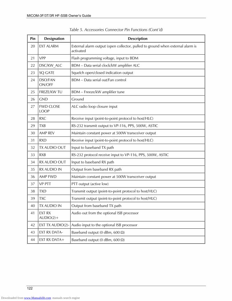
MICOM-3F/3T/3R HF-SSB Owners Guide
122
Table 5. Accessories Connector Pin Functions (Contd)
Pin Designation Description
20 EXT ALARM External alarm output (open collector, pulled to ground when external alarm is activated
21 VPP Flash programming voltage, input to BDM
22 DSC/KW_ALC BDM Data serial clock/kW amplifier ALC
23 SQ GATE Squelch open/closed indication output
24 DSO/FAN ON/OFF
BDM Data serial out/Fan control
25 FREZE/KW TU BDM Freeze/kW amplifier tune
26 GND Ground
27 FWD CLOSE LOOP
ALC radio loop closure input
28 RXC Receive input (point-to-point protocol to host/HLC)
29 TXB RS-232 transmit output to VP-116, PPS, 500W, ASTIC
30 AMP REV Maintain constant power at 500W transceiver output
31 RXD Receive input (point-to-point protocol to host/HLC)
32 TX AUDIO OUT Input to baseband TX path
33 RXB RS-232 protocol receive input to VP-116, PPS, 500W, ASTIC
34 RX AUDIO OUT Input to baseband RX path
35 RX AUDIO IN Output from baseband RX path
36 AMP FWD Maintain constant power at 500W transceiver output
37 VP PTT PTT output (active low)
38 TXD Transmit output (point-to-point protocol to host/HLC)
39 TXC Transmit output (point-to-point protocol to host/HLC)
40 TX AUDIO IN Output from baseband TX path
41 EXT RX AUDIO(2)+
Audio out from the optional ISB processor
42 EXT TX AUDIO(2)- Audio input to the optional ISB processor
43 EXT RX DATA- Baseband output (0 dBm, 600 Ω)
44 EXT RX DATA+ Baseband output (0 dBm, 600 Ω)
Downloaded from www.Manualslib.com manuals search engine
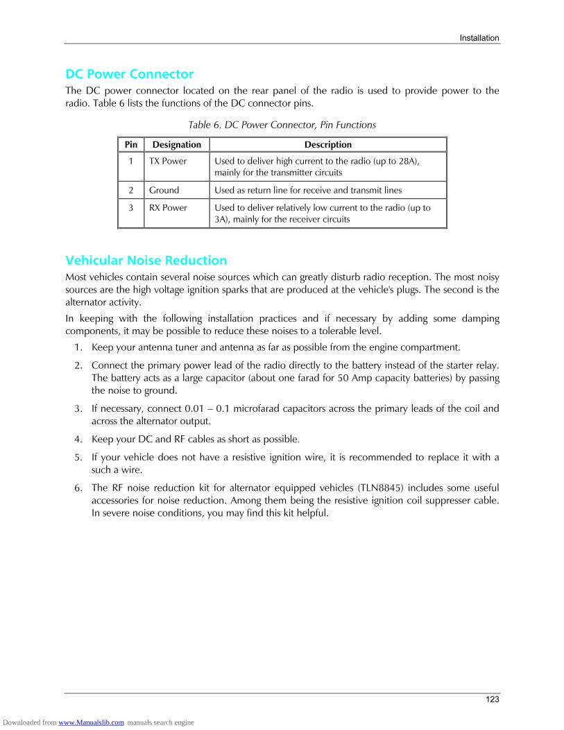
Installation
123
DC Power Connector The DC power connector located on the rear panel of the radio is used to provide power to the radio. Table 6 lists the functions of the DC connector pins.
Table 6. DC Power Connector, Pin Functions
Pin Designation Description
1 TX Power Used to deliver high current to the radio (up to 28A), mainly for the transmitter circuits
2 Ground Used as return line for receive and transmit lines
3 RX Power Used to deliver relatively low current to the radio (up to 3A), mainly for the receiver circuits
Vehicular Noise Reduction Most vehicles contain several noise sources which can greatly disturb radio reception. The most noisy sources are the high voltage ignition sparks that are produced at the vehicle's plugs. The second is the alternator activity.
In keeping with the following installation practices and if necessary by adding some damping components, it may be possible to reduce these noises to a tolerable level.
1. Keep your antenna tuner and antenna as far as possible from the engine compartment.
2. Connect the primary power lead of the radio directly to the battery instead of the starter relay. The battery acts as a large capacitor (about one farad for 50 Amp capacity batteries) by passing the noise to ground.
3. If necessary, connect 0.01 0.1 microfarad capacitors across the primary leads of the coil and across the alternator output.
4. Keep your DC and RF cables as short as possible.
5. If your vehicle does not have a resistive ignition wire, it is recommended to replace it with a such a wire.
6. The RF noise reduction kit for alternator equipped vehicles (TLN8845) includes some useful accessories for noise reduction. Among them being the resistive ignition coil suppresser cable. In severe noise conditions, you may find this kit helpful.
Downloaded from www.Manualslib.com manuals search engine

MICOM-3F/3T/3R HF-SSB Owners Guide
124
Maintenance
Introduction This section provides maintenance information for the user of the MICOM-3 radio. By carrying out the installation procedures correctly and following the maintenance instructions properly, you ensure continuous operation of your radio set.
When an internal problem appears or is suspected, the MICOM-3 internal BITE (built-in test equipment) will assist you in locating the source of this possible problem to inform the service representative accordingly.
Preventative Maintenance
System Integrity Periodically check the integrity of your system: check the power source, cables including coax cables, connectors, antenna tuner (if used) and antenna.
Carefully check that no damage has been caused to your cables; pay extra attention to runway through holes and bent cables.
Periodic Calibration To keep the frequency accuracy of your radio, it is required to calibrate its internal frequency source after 3, 6 and 12 months of operation during the first year, and once a year thereafter. Please ensure that your radio is calibrated on time.
Downloaded from www.Manualslib.com manuals search engine
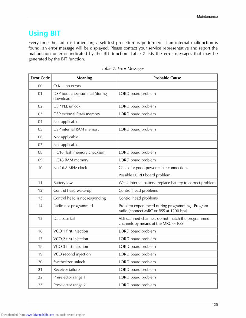
Maintenance
125
Using BIT Every time the radio is turned on, a self-test procedure is performed. If an internal malfunction is found, an error message will be displayed. Please contact your service representative and report the malfunction or error indicated by the BIT function. Table 7 lists the error messages that may be generated by the BIT function.
Table 7. Error Messages
Error Code Meaning Probable Cause
00 O.K. no errors
01 DSP boot checksum fail (during download)
LORD board problem
02 DSP PLL unlock LORD board problem
03 DSP external RAM memory LORD board problem
04 Not applicable
05 DSP internal RAM memory LORD board problem
06 Not applicable
07 Not applicable
08 HC16 flash memory checksum LORD board problem
09 HC16 RAM memory LORD board problem
10 No 16.8 MHz clock Check for good power cable connection.
Possible LORD board problem
11 Battery low Weak internal battery: replace battery to correct problem
12 Control head wake-up Control head problems
13 Control head is not responding Control head problems
14 Radio not programmed Problem experienced during programming. Program radio (connect MRC or RSS at 1200 bps)
15 Database fail ALE scanned channels do not match the programmed channels by means of the MRC or RSS
16 VCO 1 first injection LORD board problem
17 VCO 2 first injection LORD board problem
18 VCO 3 first injection LORD board problem
19 VCO second injection LORD board problem
20 Synthesizer unlock LORD board problem
21 Receiver failure LORD board problem
22 Preselector range 1 LORD board problem
23 Preselector range 2 LORD board problem
Downloaded from www.Manualslib.com manuals search engine
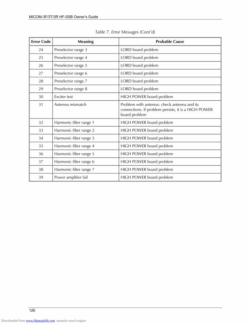
MICOM-3F/3T/3R HF-SSB Owners Guide
126
Table 7. Error Messages (Contd)
Error Code Meaning Probable Cause
24 Preselector range 3 LORD board problem
25 Preselector range 4 LORD board problem
26 Preselector range 5 LORD board problem
27 Preselector range 6 LORD board problem
28 Preselector range 7 LORD board problem
29 Preselector range 8 LORD board problem
30 Exciter test HIGH POWER board problem
31 Antenna mismatch Problem with antenna: check antenna and its connections. If problem persists, it is a HIGH POWER board problem
32 Harmonic filter range 1 HIGH POWER board problem
33 Harmonic filter range 2 HIGH POWER board problem
34 Harmonic filter range 3 HIGH POWER board problem
35 Harmonic filter range 4 HIGH POWER board problem
36 Harmonic filter range 5 HIGH POWER board problem
37 Harmonic filter range 6 HIGH POWER board problem
38 Harmonic filter range 7 HIGH POWER board problem
39 Power amplifier fail HIGH POWER board problem
Downloaded from www.Manualslib.com manuals search engine
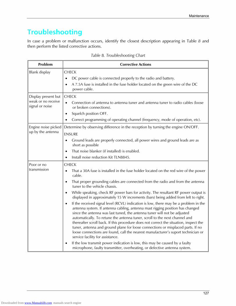
Maintenance
127
Troubleshooting In case a problem or malfunction occurs, identify the closest description appearing in Table 8 and then perform the listed corrective actions.
Table 8. Troubleshooting Chart
Problem Corrective Actions
Blank display CHECK
• DC power cable is connected properly to the radio and battery.
• A 7.5A fuse is installed in the fuse holder located on the green wire of the DC power cable.
Display present but weak or no receive signal or noise
CHECK
• Connection of antenna to antenna tuner and antenna tuner to radio cables (loose or broken connections).
• Squelch position OFF.
• Correct programming of operating channel (frequency, mode of operation, etc).
Engine noise picked up by the antenna
Determine by observing difference in the reception by turning the engine ON/OFF.
ENSURE
• Ground leads are properly connected, all power wires and ground leads are as short as possible
• That noise blanker (if installed) is enabled.
• Install noise reduction Kit TLN8845.
Poor or no transmission
CHECK
• That a 30A fuse is installed in the fuse holder located on the red wire of the power cable.
• That proper grounding cables are connected from the radio and from the antenna tuner to the vehicle chassis.
• While speaking, check RF power bars for activity. The resultant RF power output is displayed in approximately 15 W increments (bars) being added from left to right.
• If the received signal level (RCVL) indication is low, there may be a problem in the antenna system. If antenna cabling, antenna mast rigging position has changed since the antenna was last tuned, the antenna tuner will not be adjusted automatically. To retune the antenna tuner, scroll to the next channel and thereafter scroll back. If this procedure does not correct the situation, inspect the tuner, antenna and ground plane for loose connections or misplaced parts. If no loose connections are found, call the nearest manufacturers suport technician or service facility for assistance.
• If the low transmit power indication is low, this may be caused by a faulty microphone, faulty transmitter, overheating, or defective antenna system.
Downloaded from www.Manualslib.com manuals search engine
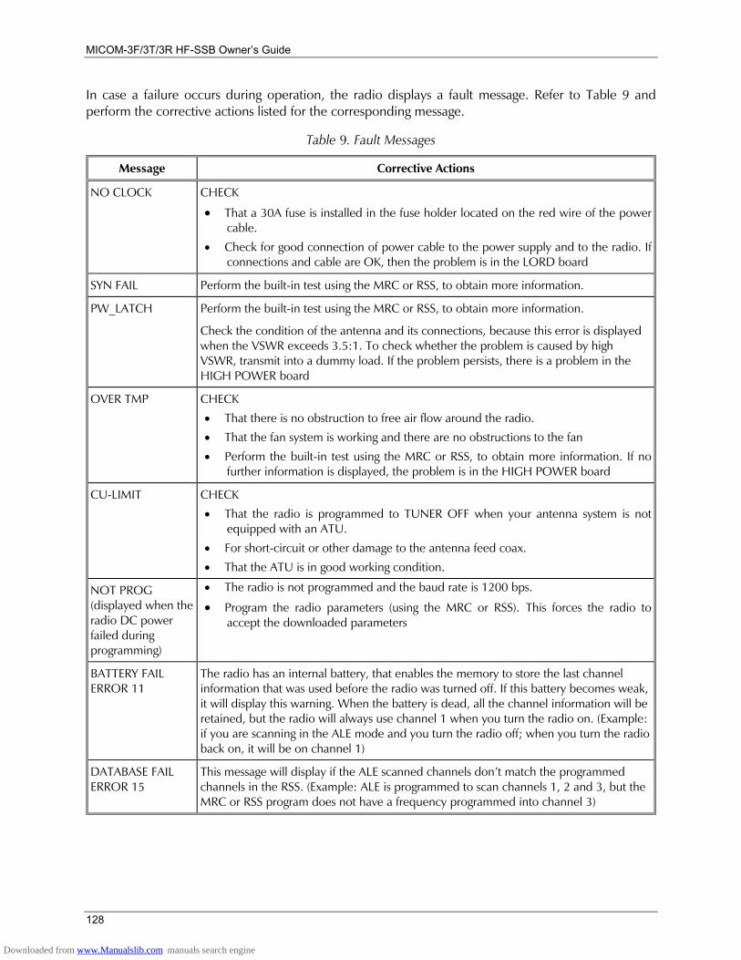
MICOM-3F/3T/3R HF-SSB Owners Guide
128
In case a failure occurs during operation, the radio displays a fault message. Refer to Table 9 and perform the corrective actions listed for the corresponding message.
Table 9. Fault Messages
Message Corrective Actions
NO CLOCK CHECK
• That a 30A fuse is installed in the fuse holder located on the red wire of the power cable.
• Check for good connection of power cable to the power supply and to the radio. If connections and cable are OK, then the problem is in the LORD board
SYN FAIL Perform the built-in test using the MRC or RSS, to obtain more information.
PW_LATCH Perform the built-in test using the MRC or RSS, to obtain more information.
Check the condition of the antenna and its connections, because this error is displayed when the VSWR exceeds 3.5:1. To check whether the problem is caused by high VSWR, transmit into a dummy load. If the problem persists, there is a problem in the HIGH POWER board
OVER TMP CHECK
• That there is no obstruction to free air flow around the radio. • That the fan system is working and there are no obstructions to the fan
• Perform the built-in test using the MRC or RSS, to obtain more information. If no further information is displayed, the problem is in the HIGH POWER board
CU-LIMIT CHECK
• That the radio is programmed to TUNER OFF when your antenna system is not equipped with an ATU.
• For short-circuit or other damage to the antenna feed coax.
• That the ATU is in good working condition.
NOT PROG (displayed when the radio DC power failed during programming)
• The radio is not programmed and the baud rate is 1200 bps.
• Program the radio parameters (using the MRC or RSS). This forces the radio to accept the downloaded parameters
BATTERY FAIL ERROR 11
The radio has an internal battery, that enables the memory to store the last channel information that was used before the radio was turned off. If this battery becomes weak, it will display this warning. When the battery is dead, all the channel information will be retained, but the radio will always use channel 1 when you turn the radio on. (Example: if you are scanning in the ALE mode and you turn the radio off; when you turn the radio back on, it will be on channel 1)
DATABASE FAIL ERROR 15
This message will display if the ALE scanned channels dont match the programmed channels in the RSS. (Example: ALE is programmed to scan channels 1, 2 and 3, but the MRC or RSS program does not have a frequency programmed into channel 3)
Downloaded from www.Manualslib.com manuals search engine
Maintenance
129
Service Proper repair and maintenance procedures will assure efficient operation and long life for this product. A maintenance agreement will provide expert service to keep this and all other communication equipment in perfect operating condition.
For a contract service agreement, please contact your nearest service representative, or sales representative at MOBAT USA, 1720 West Paul Dirac Drive, Tallahassee 32310 FL, USA ([email protected]).
Radio Checks If you suspect a radio problem, check the following items before requesting service.
• Be sure the radio is turned on.
• Replace or recharge the battery. The first time a new battery is used, it should be charged for at least 16 hours.
• The antenna must be screwed on properly, with its base flush against the top of the antenna base.
• Could your radio problem be caused by accessories improperly connected? Try operating the radio from several different locations, especially when using the radio inside buildings.
Downloaded from www.Manualslib.com manuals search engine
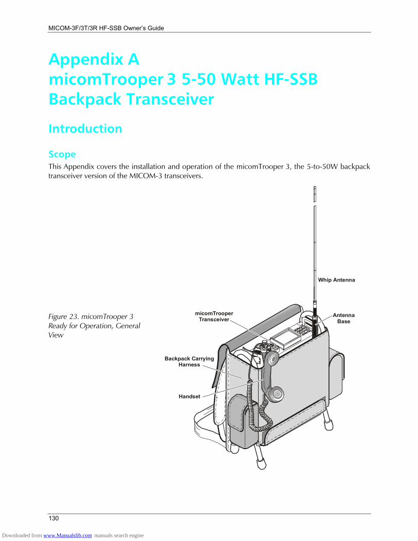
MICOM-3F/3T/3R HF-SSB Owners Guide
130
Appendix A micomTrooper 3 5-50 Watt HF-SSB Backpack Transceiver
Introduction
Scope This Appendix covers the installation and operation of the micomTrooper 3, the 5-to-50W backpack transceiver version of the MICOM-3 transceivers.
Figure 23. micomTrooper 3 Ready for Operation, General View
AntennaBase
Whip Antenna
micomTrooperTransceiver
Backpack CHarness
arrying
Handset
Downloaded from www.Manualslib.com manuals search engine
Appendix A micomTrooper 3 5-50 Watt HF-SSB Backpack Transceiver
131
micomTrooper 3 is part of the MICOM-3 family of HF-SSB radio sets; it has compatible characteristics and uses the same operating procedures as other MICOM-3 transceivers. Therefore, this manual covers only procedures specific to micomTrooper 3; the other procedures, which are common to the whole MICOM-3 product line, are described in the previous sections.
Purpose and Use micomTrooper 3 is a backpack version of the robust MICOM-3 mobile radio. For backpack operation, micomTrooper 3 is powered by a lightweight Lithium Ion rechargeable battery, has selectable power output of 5 to 20 W and high sensitivity, and uses a 1.5 meter (5 ft) flexible steel blade whip antenna matched by a built-in automatic antenna tuner unit. When necessary, micomTrooper 3 can be programmed to reach a power output of 50 W, and can also be used with dipole, long-wire and many other types of broadband antennas for static operation.
The micomTrooper 3 capabilities provide reliable long-range HF-SSB radio communications in a rugged yet lightweight backpack configuration. Designed to meet the needs of users who carry out on-foot operations in remote areas, it is built to withstand years of shock and vibration as well as severe weather conditions. micomTrooper 3 is certified for dependability and durability, and complies with US standard MIL-STD-810F.
micomTrooper 3 is equipped with a military-type handset, whip antenna, cables and connectors, delivering superior quality in a radio priced to fit the needs of a wide range of organizations. For backpack operations, micomTrooper 3 is carried in a convenient, lightweight harness that completely envelops the transceiver.
The durable aluminum frame of the harness protects against damage and allows placing the transceiver on ground for static operations.
Equipment Description
micomTrooper 3 Functional Description micomTrooper 3 is an advanced, highly backpack-portable HF-SSB transceiver that provides a complete solution to the communication requirements in the crowded HF band. micomTrooper 3 has an automatic antenna tuner, which supports a wide range of antennas, including a light-weight 1.5 meter (5 ft) whip for portable (backpack) operation. The whip antenna consists of a flexible steel blade that bends without damage when striking an obstacle, and can also be easily folded for storage. Dipole, long wire, and many other types of antennas can be used for static operation.
micomTrooper 3 provides voice, data, and telegraphy (CW) communication. Extensive use of digital signal processing ensures high performance and supports as a standard many advanced features, e.g., digital noise blanking, and offers as options features such as embedded vocoder, data modem and encryption. Moreover, new features and improvements can be easily added by software updating.
To ensure the best possible communication reliability and quality, micomTrooper 3 uses automatic frequency management and automatic link establishment (ALE), and is JITC-certified to FED-1045 and MIL-STD-188-141B. In addition, the ALE function also provides Automatic Message Display (AMD), that enables operators to exchange preprogrammed messages while establishing a link.
The transmit output power is operator-selectable (5, 10 or 20 W). When used in a backpack configuration, the operator can reduce the transmit power and thus increase battery life when the communication conditions do not require the maximum transmit power (20 W).
Downloaded from www.Manualslib.com manuals search engine
MICOM-3F/3T/3R HF-SSB Owners Guide
132
Under bad propagation conditions or in an emergency, the operator can rapidly switch to static operation by simply placing the self-supporting micomTrooper 3 harness on ground, and increasing the transmit power to 50 W.
Under static operating conditions, the operator can easily connecting a dipole or another long wire antenna instead of the whip, further increasing communication efficiency.
micomTrooper 3 is powered by a 16V, 12Ah rechargeable Lithium Ion battery, type ML1416-L. Spare batteries can be carried in the backpack harness.
Main micomTrooper 3 Operational Features This section presents a concise list of the main operational features of the micomTrooper 3 transceiver. For a complete description of all the capabilities and features of MICOM transceivers, see the Performance Specifications section.
Fast and simple radio link establishing:
• Automatic Link Establishment (ALE) per FED-1045 and MIL-STD-188-141B, JITC certified.
• ISB (Independent Sideband) ready.
• Full interoperability with other manufacturers' radios complying with the same ALE standards.
Loud and clear voice communication:
• Built-in voice quality system with proprietary DSP algorithms that filter out background noises and elevates sound bytes, providing exceptional communication clarity.
• Selectable bandwidth, for fine tuning and optimal voice reception.
• Unmatched combination of high power (up to 50 W) and high sensitivity (0.3 µV) for outstanding communication coverage.
• Voice-activated digital squelch. User-friendly operation:
• Large alphanumeric front panel display and keyboard for programming and set-up.
• Large LCD, full-dot matrix digital display and an enhanced keyboard for programming and set-up.
• Radio can be operated using any standard USB keyboard (requires USB option).
• Support for multiple languages.
• Transceiver can be controlled using PC and programming application. Years of trouble-free, advanced communications.
• Upgrading to future technologies is easily made by installing new software into the transceiver's DSP unit.
• Easily replaceable digital components ensure cost-effective maintenance and repair.
• Very high MTBF, as with all MICOM radios.
• Unique Built-In Self Test system that provides exceptional diagnostic capability. Comprehensive communication and networking services
• Office-quality communication services integrating fax, e-mail and data transmission and reception.
Downloaded from www.Manualslib.com manuals search engine
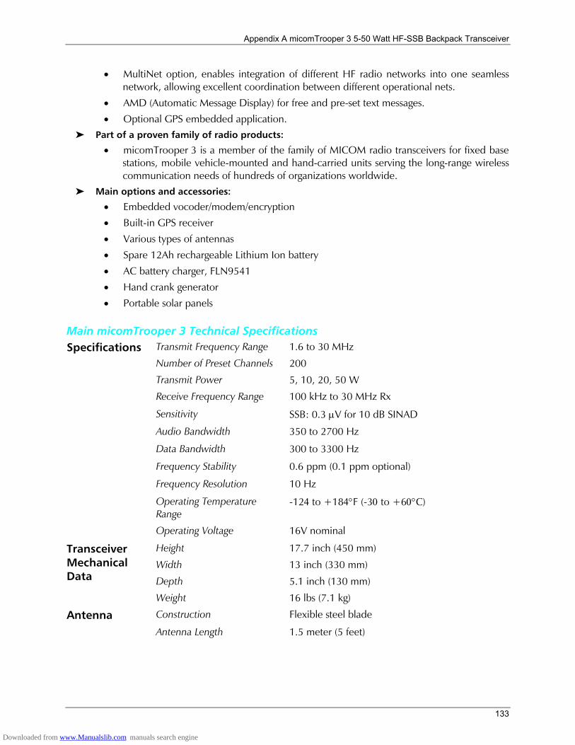
Appendix A micomTrooper 3 5-50 Watt HF-SSB Backpack Transceiver
133
• MultiNet option, enables integration of different HF radio networks into one seamless network, allowing excellent coordination between different operational nets.
• AMD (Automatic Message Display) for free and pre-set text messages.
• Optional GPS embedded application. Part of a proven family of radio products:
• micomTrooper 3 is a member of the family of MICOM radio transceivers for fixed base stations, mobile vehicle-mounted and hand-carried units serving the long-range wireless communication needs of hundreds of organizations worldwide.
Main options and accessories:
• Embedded vocoder/modem/encryption
• Built-in GPS receiver
• Various types of antennas
• Spare 12Ah rechargeable Lithium Ion battery
• AC battery charger, FLN9541
• Hand crank generator
• Portable solar panels
Main micomTrooper 3 Technical Specifications Transmit Frequency Range 1.6 to 30 MHz
Number of Preset Channels 200 Specifications
Transmit Power 5, 10, 20, 50 W
Receive Frequency Range 100 kHz to 30 MHz Rx
Sensitivity SSB: 0.3 µV for 10 dB SINAD
Audio Bandwidth 350 to 2700 Hz
Data Bandwidth 300 to 3300 Hz
Frequency Stability 0.6 ppm (0.1 ppm optional)
Frequency Resolution 10 Hz
Operating Temperature Range
-124 to +184°F (-30 to +60°C)
Operating Voltage 16V nominal
Height 17.7 inch (450 mm)
Width 13 inch (330 mm)
Depth 5.1 inch (130 mm)
Transceiver Mechanical Data
Weight 16 lbs (7.1 kg)
Antenna Construction Flexible steel blade
Antenna Length 1.5 meter (5 feet)
Downloaded from www.Manualslib.com manuals search engine
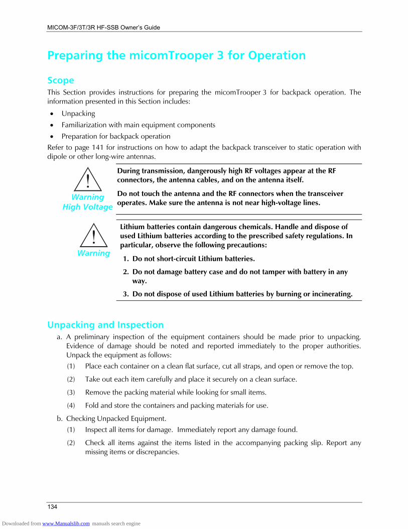
MICOM-3F/3T/3R HF-SSB Owners Guide
134
Preparing the micomTrooper 3 for Operation
Scope This Section provides instructions for preparing the micomTrooper 3 for backpack operation. The information presented in this Section includes:
• Unpacking
• Familiarization with main equipment components
• Preparation for backpack operation Refer to page 141 for instructions on how to adapt the backpack transceiver to static operation with dipole or other long-wire antennas.
Warning
High Voltage
During transmission, dangerously high RF voltages appear at the RF connectors, the antenna cables, and on the antenna itself.
Do not touch the antenna and the RF connectors when the transceiver operates. Make sure the antenna is not near high-voltage lines.
Warning
Lithium batteries contain dangerous chemicals. Handle and dispose of used Lithium batteries according to the prescribed safety regulations. In particular, observe the following precautions:
1. Do not short-circuit Lithium batteries.
2. Do not damage battery case and do not tamper with battery in any way.
3. Do not dispose of used Lithium batteries by burning or incinerating.
Unpacking and Inspection a. A preliminary inspection of the equipment containers should be made prior to unpacking.
Evidence of damage should be noted and reported immediately to the proper authorities. Unpack the equipment as follows: (1) Place each container on a clean flat surface, cut all straps, and open or remove the top.
(2) Take out each item carefully and place it securely on a clean surface.
(3) Remove the packing material while looking for small items.
(4) Fold and store the containers and packing materials for use.
b. Checking Unpacked Equipment. (1) Inspect all items for damage. Immediately report any damage found.
(2) Check all items against the items listed in the accompanying packing slip. Report any missing items or discrepancies.
Downloaded from www.Manualslib.com manuals search engine
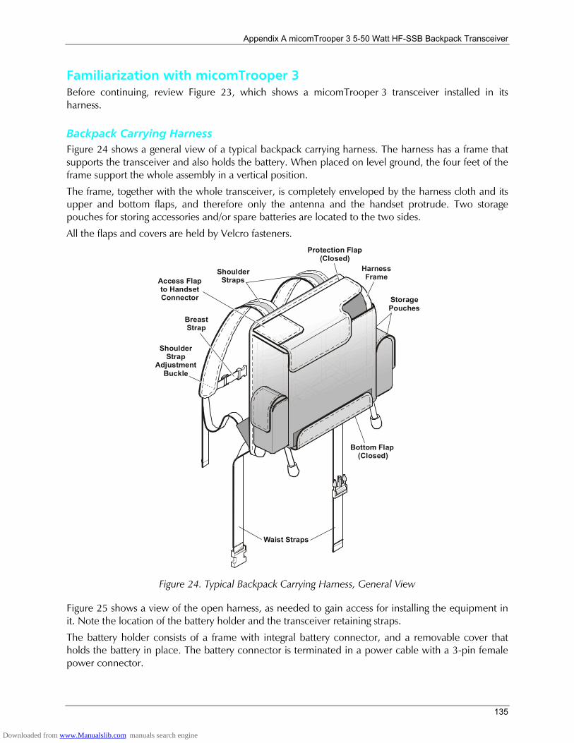
Appendix A micomTrooper 3 5-50 Watt HF-SSB Backpack Transceiver
135
Familiarization with micomTrooper 3 Before continuing, review Figure 23, which shows a micomTrooper 3 transceiver installed in its harness.
Backpack Carrying Harness Figure 24 shows a general view of a typical backpack carrying harness. The harness has a frame that supports the transceiver and also holds the battery. When placed on level ground, the four feet of the frame support the whole assembly in a vertical position.
The frame, together with the whole transceiver, is completely enveloped by the harness cloth and its upper and bottom flaps, and therefore only the antenna and the handset protrude. Two storage pouches for storing accessories and/or spare batteries are located to the two sides.
All the flaps and covers are held by Velcro fasteners.
Shoulder Strap
AdjustmentBuckle
Bottom Flap (Closed)
StoragePouches
ShoulderStrapsAccess Flap
to HandsetConnector
BreastStrap
Protection Flap(Closed)
Waist Straps
HarnessFrame
Figure 24. Typical Backpack Carrying Harness, General View
Figure 25 shows a view of the open harness, as needed to gain access for installing the equipment in it. Note the location of the battery holder and the transceiver retaining straps.
The battery holder consists of a frame with integral battery connector, and a removable cover that holds the battery in place. The battery connector is terminated in a power cable with a 3-pin female power connector.
Downloaded from www.Manualslib.com manuals search engine
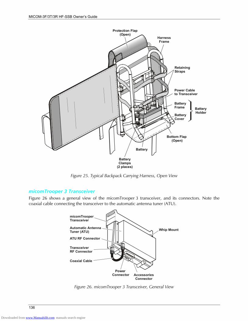
MICOM-3F/3T/3R HF-SSB Owners Guide
136
Bottom Flap (Open)
BatteryCover
BatteryHolder
BatteryClamps
(2 places)
Battery
Protection Flap(Open)
HarnessFrame
RetainingStraps
BatteryFrame
Power Cableto Transceiver
Figure 25. Typical Backpack Carrying Harness, Open View
micomTrooper 3 Transceiver Figure 26 shows a general view of the micomTrooper 3 transceiver, and its connectors. Note the coaxial cable connecting the transceiver to the automatic antenna tuner (ATU).
micomTrooperTransceiver
Automatic AntennaTuner (ATU)
ATU RF Connector
TransceiverRF Connector
Power Connector Accessories
Connector
Coaxial Cable
Whip Mount
Figure 26. micomTrooper 3 Transceiver, General View
Downloaded from www.Manualslib.com manuals search engine

Appendix A micomTrooper 3 5-50 Watt HF-SSB Backpack Transceiver
137
Preparing micomTrooper 3 for Backpack Operation To prepare the micomTrooper 3 for static operation, refer to page 141.
Outline of Preparation Procedures The preparation of a micomTrooper 3 transceiver for operation includes:
1. Installation of transceiver in carrying harness.
2. Installation of battery.
3. Installation of antenna and audio accessories.
4. When ready to go − wearing the backpack carrying harness.
Installation of micomTrooper 3 in Carrying Harness
Warning
Before starting, make sure that the transceiver is off by turning the volume control fully counterclockwise beyond the detent (you should hear a click).
1. Place the carrying harness on a level surface, with the metal braces facing upward.
2. If necessary, open the harness protection flap.
Note For clarity, the figure at the right does not show the harness.
3. Place the micomTrooper 3 on the top of the carrying harness, with its front panel upwards and its rear resting on the carrying harness (see figure). Note position of audio connectors: they must be on the left.
4. Connect the three-pin D-type power connector of the power cable to the micomTrooper 3 power connector. Fasten securely the two connector screws.
5. Push the transceiver down, toward the battery, until it is stopped by the aluminum frame.
Battery
Transceiver
PowerConnector
PowerCable
Downloaded from www.Manualslib.com manuals search engine
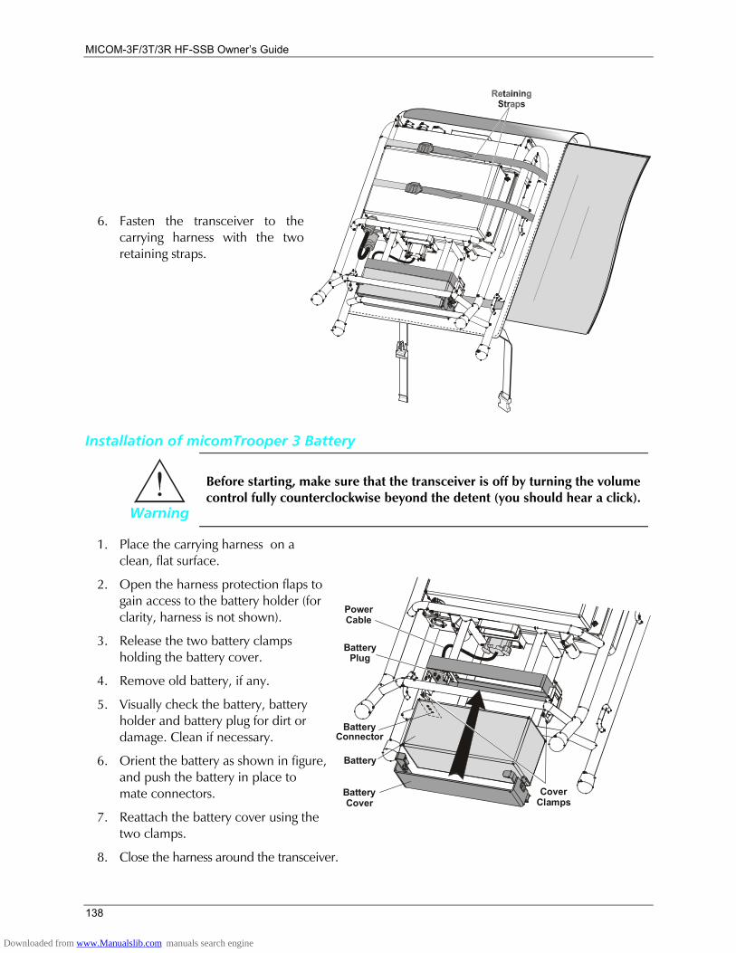
MICOM-3F/3T/3R HF-SSB Owners Guide
138
6. Fasten the transceiver to the carrying harness with the two retaining straps.
Installation of micomTrooper 3 Battery
Warning
Before starting, make sure that the transceiver is off by turning the volume control fully counterclockwise beyond the detent (you should hear a click).
1. Place the carrying harness on a clean, flat surface.
2. Open the harness protection flaps to gain access to the battery holder (for clarity, harness is not shown).
3. Release the two battery clamps holding the battery cover.
4. Remove old battery, if any.
5. Visually check the battery, battery holder and battery plug for dirt or damage. Clean if necessary.
6. Orient the battery as shown in figure, and push the battery in place to mate connectors.
7. Reattach the battery cover using the two clamps.
BatteryCover
Battery
BatteryPlug
BatteryConnector
PowerCable
CoverClamps
8. Close the harness around the transceiver.
Downloaded from www.Manualslib.com manuals search engine
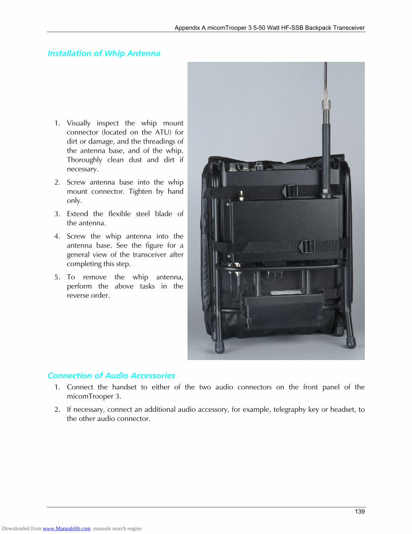
Appendix A micomTrooper 3 5-50 Watt HF-SSB Backpack Transceiver
139
Installation of Whip Antenna
1. Visually inspect the whip mount connector (located on the ATU) for dirt or damage, and the threadings of the antenna base, and of the whip. Thoroughly clean dust and dirt if necessary.
2. Screw antenna base into the whip mount connector. Tighten by hand only.
3. Extend the flexible steel blade of the antenna.
4. Screw the whip antenna into the antenna base. See the figure for a general view of the transceiver after completing this step.
5. To remove the whip antenna, perform the above tasks in the reverse order.
Connection of Audio Accessories 1. Connect the handset to either of the two audio connectors on the front panel of the
micomTrooper 3.
2. If necessary, connect an additional audio accessory, for example, telegraphy key or headset, to the other audio connector.
Downloaded from www.Manualslib.com manuals search engine

MICOM-3F/3T/3R HF-SSB Owners Guide
140
Wearing the Backpack Carrying Harness
To wear the backpack:
1. Put harness on your back by inserting arms through shoulder straps.
2. Tighten shoulder straps.
3. Buckle waist straps to belt and adjust to size.
4. Adjust the breast strap length and then attach the strap.
At this stage, the micomTrooper 3 is ready for use as a backpack radio set.
Shoulder Strap
AdjustmentBuckle
Bottom Flap (Closed)
ShoulderStraps
BreastStrap
Protection Flap(Closed)
WaistStrap
Operating Instructions
Note When using the micomTrooper 3 with its whip antenna, make sure to select YES for the TUNER option (MENU>MORE>PROG>RAD>OPTS).
When using the micomTrooper 3 with a dipole or long wire antenna (static operation as described on page 141), make sure to select NO for the TUNER option.
1. Turn the micomTrooper 3 ON/OFF switch and volume control clockwise, and adjust for a comfortable listening level.
2. You are now ready to start using the micomTrooper 3. For operating procedures, use the information appearing in the previous Chapters.
3. To turn the micomTrooper 3 off, turn its ON/OFF switch and volume control fully counterclockwise, beyond the detent position.
Downloaded from www.Manualslib.com manuals search engine
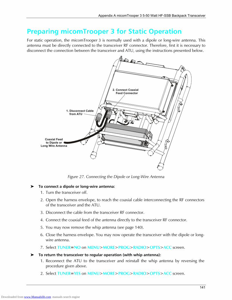
Appendix A micomTrooper 3 5-50 Watt HF-SSB Backpack Transceiver
141
Preparing micomTrooper 3 for Static Operation For static operation, the micomTrooper 3 is normally used with a dipole or long-wire antenna. This antenna must be directly connected to the transceiver RF connector. Therefore, first it is necessary to disconnect the connection between the transceiver and ATU, using the instructions presented below.
Coaxial Feedto Dipole or
Long Wire Antenna
2. Connect Coaxial Feed Connector
1. Disconnect Cable from ATU
Figure 27. Connecting the Dipole or Long-Wire Antenna
To connect a dipole or long-wire antenna:
1. Turn the transceiver off.
2. Open the harness envelope, to reach the coaxial cable interconnecting the RF connectors of the transceiver and the ATU.
3. Disconnect the cable from the transceiver RF connector.
4. Connect the coaxial feed of the antenna directly to the transceiver RF connector.
5. You may now remove the whip antenna (see page 140).
6. Close the harness envelope. You may now operate the transceiver with the dipole or long-wire antenna.
7. Select TUNER=NO on MENU>MORE>PROG>RADIO>OPTS>ACC screen.
To return the transceiver to regular operation (with whip antenna):
1. Reconnect the ATU to the transceiver and reinstall the whip antenna by reversing the procedure given above.
2. Select TUNER=YES on MENU>MORE>PROG>RADIO>OPTS>ACC screen.
Downloaded from www.Manualslib.com manuals search engine
MICOM-3F/3T/3R HF-SSB Owners Guide
142
Using the micomTrooper 3 Battery Charger, FLN9541
Purpose and Use FLN9541 is an AC-powered battery charger designed to charge 16V, 12Ah Lithium Ion rechargeable batteries of the type used by micomTrooper 3 (ML1416-L).
FLN9541 is simple to operate and does not require operator attendance during operation. Yet it provides advanced features, such as fully automatic charging and automatic turn-off after battery charging is completed. Three indicators display the operating state, and sounds are used to signal proper connection of battery, end of charge, etc.
FLN9541 has only two controls:
• POWER on/off switch. When the FLN9541 is turned on, a green indicator, UDC, lights to indicate that the charger is OK.
• CHARGE pushbutton (red): after connecting the battery to be charged, press the pushbutton to start charging. While charging, a yellow CHARGE indicator lights. The end of charge is indicated by the flashing of a green FINISH CHARGE indicator.
The battery charger is a compact unit, intended for use in rooms, shelters, etc. Do not expose the battery charger to direct sun radiation or excessive temperatures, rain, snow, or high humidity. Keep charger battery contacts clean and avoid accidental short-circuits by turning the charger on only after a battery is installed on the charger.
FLN9541 Operating Instructions 1. Place the battery charger on a flat surface, protected from sun and rain.
2. Insert the charger power cable plug into an AC outlet.
3. Connect the battery to be charged to the battery charger: place the battery socket over the charger pins and press firmly to mate (the connectors will mate only if battery is placed with the correct orientation). Beeps must be heard, to indicate proper contact with the charger.
Note Beeps must be heard, to indicate proper contact with the charger.
If no beeps are heard, remove and then reconnect the battery. Also check that the charger pins are clean. If no beeps are heard after the battery is reconnected, the battery is probably bad and cannot be recharged.
4. Turn the charger on by setting its front panel POWER switch to ON:
• The green UDC indicator will light
• The green FINISH CHARGE starts flashing, and a tone is heard. 5. Start the charging by pressing the red CHARGE pushbutton. The yellow CHARGE indicator will
turn on and the tone stops.
Note If the battery is faulty or makes bad contact with the battery charger, the CHARGE indicator will not turn on after pressing the CHARGE pushbutton, and no charge current is supplied to the battery.
6. The charger now operates automatically.
Downloaded from www.Manualslib.com manuals search engine
Appendix A micomTrooper 3 5-50 Watt HF-SSB Backpack Transceiver
143
Note If a power source failure occurs while the battery is being charged, the FINISH CHARGE starts flashing, and an alarm tone is heard. To resume charging after power returns, press again the red CHARGE pushbutton.
7. You will be notified when the battery is fully charged: the FINISH CHARGE indicator will start flashing and the tone is heard again.
8. At this stage, set the POWER switch to OFF, and remove the battery from the charger.
9. Disconnect the charger power cable from the AC outlet.
Main FLN9541 Technical Specifications Input voltage 90 to 265 VAC, 20 to 60 Hz
Charged battery voltage 16.8 ±0.2 V
Charging current 3.6 A
Dimensions 220 × 165 × 50 mm
Weight 1.25 kg
Downloaded from www.Manualslib.com manuals search engine
MICOM-3F/3T/3R HF-SSB Owners Guide
144
List of Procedures This section presents a list of the main activities explained in this manual and a reference to the location of the procedure in the manual.
What you want to do Go to page
To display the menu:.......................................................................................................... 14 To exit the menu and return to the previous working mode (e.g., CHAN or FREQ):............ 14 To turn the radio on: ..........................................................................................................16 To turn the radio off: .......................................................................................................... 16 To transmit a voice message: .............................................................................................. 17 To receive calls:.................................................................................................................. 17 To enter the Channel mode: .............................................................................................. 18 To select Channel mode options: ....................................................................................... 19 To choose a channel: ......................................................................................................... 21 To enter the frequency mode: ............................................................................................ 23 To change the current frequency/frequencies: .................................................................... 23 To operate the VFO function:............................................................................................. 25 To return to the regular Frequency mode: .......................................................................... 26 To select frequency mode options: ..................................................................................... 27 To store a frequency in a channel:...................................................................................... 29 To enter the Scan mode: .................................................................................................... 30 To enter the BIT mode: ...................................................................................................... 31 To lock the radio: ............................................................................................................... 32 To unlock the radio: ........................................................................................................... 32 To enter the Password mode: ............................................................................................. 33 To enter the ALE mode: ..................................................................................................... 43 Receiving an individual call: ............................................................................................... 45 Receiving a net call:............................................................................................................ 46 Receiving an AllCall:........................................................................................................... 46 Receiving an AnyCall:......................................................................................................... 46 Receiving a sounding call:................................................................................................... 47 Receiving a bidirectional handshake call:............................................................................ 47 To answer an incoming call: ............................................................................................... 47 To display LQA for the received call: .................................................................................. 47 To select link mode options:............................................................................................... 48 To replace the channel:...................................................................................................... 51
Downloaded from www.Manualslib.com manuals search engine
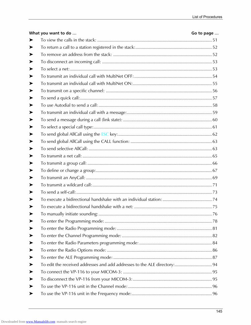
List of Procedures
145
What you want to do Go to page
To view the calls in the stack: ............................................................................................. 51 To return a call to a station registered in the stack:.............................................................. 52 To remove an address from the stack: ................................................................................ 52 To disconnect an incoming call: ......................................................................................... 53 To select a net: ................................................................................................................... 53 To transmit an individual call with MultiNet OFF:............................................................... 54 To transmit an individual call with MultiNet ON:................................................................ 55 To transmit on a specific channel: ...................................................................................... 56 To send a quick call:........................................................................................................... 57 To use Autodial to send a call: ............................................................................................ 58 To transmit an individual call with a message:..................................................................... 59 To send a message during a call (link state): ........................................................................ 60 To select a special call type:................................................................................................ 61 To send global AllCall using the ESC key:............................................................................ 62 To send global AllCall using the CALL function: .................................................................. 63 To send selective AllCall: .................................................................................................... 63 To transmit a net call: ......................................................................................................... 65 To transmit a group call: ..................................................................................................... 66 To define or change a group:.............................................................................................. 67 To transmit an AnyCall: ...................................................................................................... 69 To transmit a wildcard call:................................................................................................. 71 To send a self-call:.............................................................................................................. 73 To execute a bidirectional handshake with an individual station: ........................................ 74 To execute a bidirectional handshake with a net: ............................................................... 75 To manually initiate sounding:............................................................................................ 76 To enter the Programming mode:....................................................................................... 78 To enter the Radio Programming mode: ............................................................................. 81 To enter the Channel Programming mode: ......................................................................... 82 To enter the Radio Parameters programming mode:........................................................... 84 To enter the Radio Options mode: ..................................................................................... 86 To enter the ALE Programming mode: ................................................................................ 87 To edit the received addresses and add addresses to the ALE directory:.............................. 94 To connect the VP-116 to your MICOM-3: ........................................................................ 95 To disconnect the VP-116 from your MICOM-3:................................................................ 95 To use the VP-116 unit in the Channel mode:.................................................................... 96 To use the VP-116 unit in the Frequency mode:................................................................. 96
Downloaded from www.Manualslib.com manuals search engine
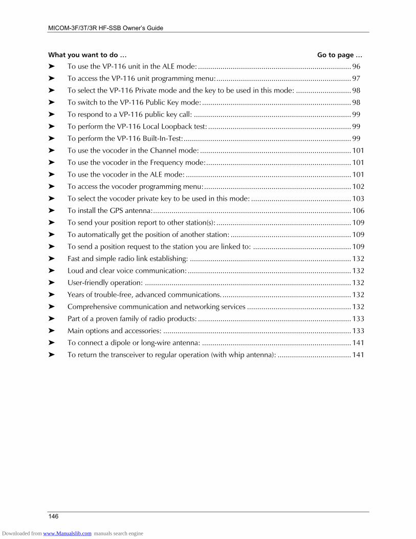
MICOM-3F/3T/3R HF-SSB Owners Guide
146
What you want to do Go to page
To use the VP-116 unit in the ALE mode:........................................................................... 96 To access the VP-116 unit programming menu:.................................................................. 97 To select the VP-116 Private mode and the key to be used in this mode: ........................... 98 To switch to the VP-116 Public Key mode:......................................................................... 98 To respond to a VP-116 public key call: ............................................................................. 99 To perform the VP-116 Local Loopback test: ...................................................................... 99 To perform the VP-116 Built-In-Test:.................................................................................. 99 To use the vocoder in the Channel mode: .......................................................................... 101 To use the vocoder in the Frequency mode:....................................................................... 101 To use the vocoder in the ALE mode: ................................................................................. 101 To access the vocoder programming menu:........................................................................ 102 To select the vocoder private key to be used in this mode: ................................................. 103 To install the GPS antenna:................................................................................................. 106 To send your position report to other station(s):.................................................................. 109 To automatically get the position of another station: ........................................................... 109 To send a position request to the station you are linked to: ................................................ 109 Fast and simple radio link establishing: ............................................................................... 132 Loud and clear voice communication: ................................................................................ 132 User-friendly operation: ..................................................................................................... 132 Years of trouble-free, advanced communications................................................................ 132 Comprehensive communication and networking services ................................................... 132 Part of a proven family of radio products: ........................................................................... 133 Main options and accessories: ............................................................................................ 133 To connect a dipole or long-wire antenna: ......................................................................... 141 To return the transceiver to regular operation (with whip antenna): .................................... 141
Downloaded from www.Manualslib.com manuals search engine