michigan wisconsin pipe line company - bsee · pdf filemichigan wisconsin pipe line company...
TRANSCRIPT
. , A
O N E W O O D W A R D A V E r D E T R O I T , M I C H I G A N - 4 3 9 2 6
J O H N F. C O T A . V I C E P R E S I D E N T
E N G I N E E R I N G A N D C O N S T R U C T I O N A D M I N I S T R A T I O N
MICHIGAN WISCONSIN PIPE LINE COMPANY M E M B E R D F T H E A M E R I C A N N A T U R A L R E S O U R C E S S Y S T E M
June 7, 1979
H-2502-B MW-0S-1A.2
Mr. John L. Rankin, Manager New Orleans OCS Office Bureau of Land Management Hale Boggs Federal Building 500 Camp Street, Suite 841 New Orleans, LA 70130
RE: Application f o r Right of Way of a Proposed 24-Inch p i p e l i n e Located From Block 137 South Marsh Island Area, South Addition to Block 397, Vermilion Area, South Addition, Offshore Louisiana, Gulf of Mexico
Dear Mr. Rankin:
Pursuant to the aut h o r i t y granted i n Section 5(c) of the Outer Continental Shelf Lands Act of August 7, 1953 (67 Stat. 462), as amended hy Public Law 95-372 e f f e c t i v e September 18, 1978, and i n compliance w i t h the regulations contained i n T i t l e 43, Subpart 2883, Section 2883.1, T i t l e 30, Subpart 250, Section 250.19 and the requirements, contained i n OCS Orders 8 and 9 issued January, 1977, Michigan Wisconsin Pipe Line Company hereby applies, i n t r i p l i c a t e , f o r the i n s t a l l a t i o n of a 24-inch natural gas p i p e l i n e as shown on the f o l l o w i n g drawings:
Hazard Survey Report
V i c i n i t y , Route, P r o f i l e and Cathodic Protection Drawing No. 625-32-1
Safety Schematic Drawing No. PL-625-32-1
The 2A-inch p i p e l i n e w i l l be used to transport natural gas from the Block 397 platform. Vermilion Area, South Addition to a subsea t i e - i n located i n Block 137, South Marsh Island Area, South Addition, Gulf of Mexico.

Mr. John L. Rankin June 7, 1979 Page 2
I n accordance w i t h applicable regulations, the applicant agrees i t w i l l m a il to each lessee or r i g h t of way holder whose lease or r i g h t of way i s affec t e d by t h i s a p p l i c a t i o n , by registered mail, return receipt requested, a copy of the a p p l i c a t i o n and the maps attached hereto. A l i s t of such lessees and r i g h t of way holders i s attached and copies of the r e t u r n r e c e i p t s showing service upon such lessees and r i g h t of way holders w i l l be forwarded t o your o f f i c e when received.
As set f o r t h i n the February 13, 1978 guidelines and amendments thereto, the applicant agrees to the following:
1. The 24-inch pip e l i n e w i l l not require b u r i a l inasmuch as the e n t i r e l i n e i s i n water depths greater than 200 fee t .
2. The proposed pipeline w i l l cross the following e x i s t i n g p i p e l i n e s :
1. Shell 6-inch pipeline 2. Marathon 8-inch pipeline 3. F l o r i d a Gas 10-inch pipeline
3. A l l valves and f i t t i n g s on the submerged p i p e l i n e w i l l be buried t o a minimum of one (1) foot below the mud l i n e .
4. Sensing devices and f a i l close valves w i l l be i n s t a l l e d as shown on the enclosed Schematic Drawing No. PL-625-32-1.
5. Three (3) copies of the Hazard Survey Report prepared by .John: IChance and Associates, Inc. and approved f o r our use are enclosed.
6. A l l changes, additions or deletions to any equipment on the p i p e l i n e w i l l be made only a f t e r f i r s t securing the expressed w r i t t e n approval of your o f f i c e .
7. Your o f f i c e w i l l be n o t i f i e d at least f i v e (5) days p r i o r to commencing construction and w i l l be advised of construction date, approximate s t a r t i n g time, s t a r t i n g point, name of contractor and barge, a v a i l a b i l i t y of h e l i p o r t f a c i l i t i e s and approximate completion date.
8. Your o f f i c e w i l l be n o t i f i e d f o r t y - e i g h t hours i n advance of the hydrostatic test and w i l l be advised of the l o c a t i o n of the pressure recorder and approximate s t a r t i n g time of the t e s t . Hydrostatic t e s t data, including procedure, hold time and r e s u l t s w i l l be furnished your o f f i c e w i t h i n ninety (90) days following the t e s t .
9
Mr. John L. Rankin June 7, 1979 Page 3
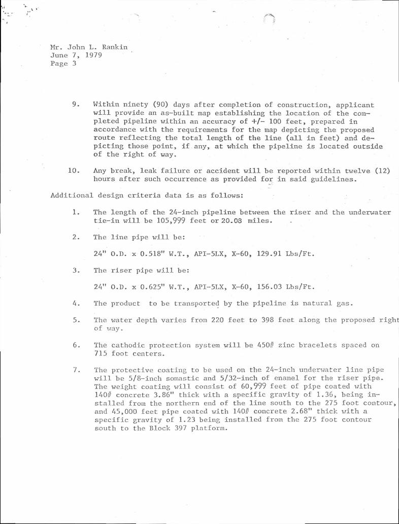
9. Within ninety (90) days a f t e r completion of construction, applicant w i l l provide an a s - b u i l t map establishing the l o c a t i o n of the completed pipeline w i t h i n an accuracy of +/- 100 f e e t , prepared i n accordance with the requirements f o r the map depicting the proposed route r e f l e c t i n g the t o t a l length of the l i n e ( a l l i n f e e t ) and dep i c t i n g those point, i f any, at which the pipeline i s located outside of the r i g h t of way.
10. Any break, leak f a i l u r e or accident w i l l be reported w i t h i n twelve (12) hours a f t e r such occurrence as provided f o r i n said guidelines.
A d d i t i o n a l design c r i t e r i a data i s as follows:
1. The length of the 24-inch pipeline between the r i s e r and the underwater t i e - i n w i l l be 105,999 feet or 20.03 miles.
2. The l i n e pipe w i l l be:
24" O.D. x 0.518" W.T., API-5LX, X-60, 129.91 Lbs/Ft.
3. The r i s e r pipe w i l l be:
24" O.D. x 0.625" W.T., API-5LX, X-60, 156.03 Lbs/Ft.
4. The product to be transported by the pipeline i s natural gas.
5. The water depth varies from 220 feet to 398 feet along the proposed r i g h t o f way.
6. The cathodic protection system w i l l be 450// zinc bracelets spaced on 715 foot centers.
7. The protective coating to be used on the 24-inch underwater l i n e pipe w i l l be 5/8-inch somastic and 5/32-inch of enamel f o r the r i s e r pipe. The weight coating w i l l consist of 60,999 feet of pipe coated w i t h 140// concrete 3.86" thick w i t h a specific g r a v i t y of 1.36, being i n s t a l l e d from the northern end of the l i n e south to the 275 f o o t contour, and 45,000 feet pipe coated with 140/! concrete 2.68" t h i c k w i t h a s p e c i f i c gravity of 1.23 being i n s t a l l e d from the 275 foot contour south to the Block 397 platform.

Mr. John L. Rankin June 7, 1979 Page A
8. The 30-inch casing pipe used on the r i s e r section w i l l be coated w i t h Endcor 750 Primer and 772 top coat.
9. The bulk s p e c i f i c gravity of the empty pipe i n seawater i s 1.36 f o r ' 60,999 feet of pipe w i t h 3.86 inches of concrete and 1.23 s p e c i f i c
g r a v i t y f o r the 45,000 feet of pipe with 2.68 inches of concrete.
10. The an t i c i p a t e d specific gravity of the natural gas i s 0.60.
11. The operating pressure of the 24-inch pip e l i n e w i l l be 1300 psig.
Maximum Allowable Operating Pressure w i l l be 1440 psig.
Maximum Allowable Operating Pressure based on l i n e pipe i s .
MAOP = 2 ST x F x E x T D
MAOP = 2(60,000) x 0.518" x 0.72 x 1.0 x 1.0 = 1864 psig (24)
Maximum Allowable Operating Pressure based on the' r i s e r piping i s :
MAOP = 2(60,000) x 0.625" x 0.50 x 1.0 x 1.0 = 1562 psig (24)
12. The design capacity of the 24-inch p i p e l i n e i s 120 MMCFD.
13. The 24-inch pipeline w i l l be h y d r o s t a t i c a l l y tested at pressures ranging from 2460 psig to 2455 psig and held f o r 24 hours. The r i s e r section w i l l be pretested p r i o r to i n s t a l l a t i o n to 2800 psig f o r 24 hours.
14. A l l pi p i n g , f i t t i n g s , r i s e r s and components of the p i p e l i n e are designed i n compliance with 49 CFR 192. F i t t i n g s are 600// ANSI or greater.
15. Construction information:
Estimated S t a r t i n g Date: September 1, 1979 Method of Construction: Lay Barge Method of B u r i a l : Bury Barge f o r Valves and Risers O Estimated Time Required to Lay and Bury Pipe: 60 days Estimated Time to Complete Project: 60 days.
Mr. John L. Rankin June 7, 1979 Page 5
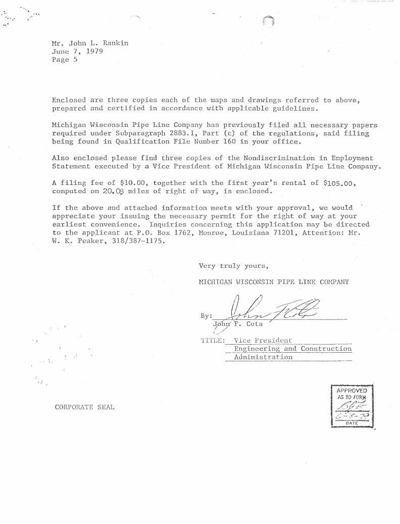
Enclosed are three copies each of the maps and drawings referred to above, prepared and c e r t i f i e d i n accordance with applicable guidelines.
Michigan Wisconsin Pipe Line Company has previously f i l e d a l l necessary papers required under Subparagraph 2883.1, Part (c) of the regulations, said f i l i n g being found i n Q u a l i f i c a t i o n F i l e Number 160 i n your o f f i c e .
Also enclosed please f i n d three copies of the Nondiscrimination i n Employment Statement executed by a Vice President of Michigan Wisconsin Pipe Line Company,
A f i l i n g fee of $10.00, together w i t h the f i r s t year's r e n t a l of $105.00, computed on 20,Cg miles of r i g h t of way, i s enclosed.
I f the above and attached information meets with your approval, we would appreciate your issuing the necessary permit f o r the r i g h t of way at your e a r l i e s t convenience. I n q u i r i e s concerning t h i s a p p l i c a t i o n may be directed to the applicant at P.O. Box 1762, Monroe, Louisiana 71201, A t t e n t i o n : Mr. W. K. Peaker, 318/387-1175.
Very t r u l y yours,
MICHIGAN WISCONSIN PIPE LINE COMPANY
TITLE: Vice President Engineering and Construction Administration
CORPORATE SEAL
APPROVED AS TO FORM
DATE
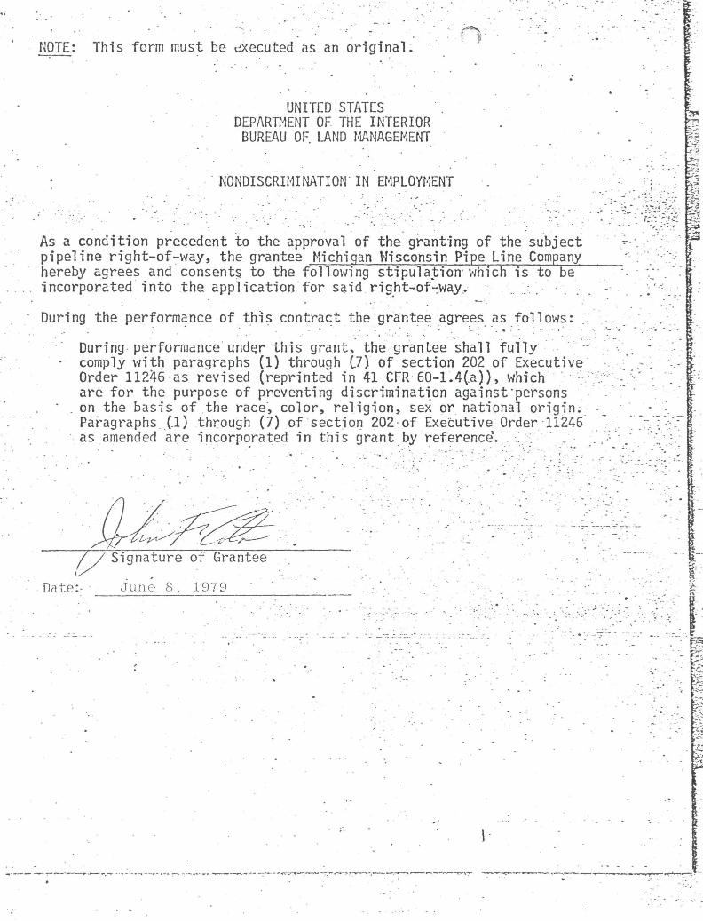
NOTE: This form must be executed as an original.
UNITED STATES DEPARTMENT OF THE INTERIOR BUREAU OF LAND MANAGEMENT
NONDISCRIMINATION IN EMPLOYMENT
As a condition precedent to the approval of the granting of the subject pipeline right-of-way, the grantee Michigan Wisconsin Pipe Line Company hereby agrees and consents to the following stipulation which is to be incorporated into the application for said right-of-way.. ..• .-
During the performance of this contract the grantee agrees as follows:
During performance undqr this grant* the grantee shall fully • • comply with paragraphs (1) through (7) of section 202 of Executive
Order 11245 as revised (reprinted in 41 CFR 60-1.4ta)), which are for the purpose of preventing discrimination against persons
" . on the basis of the race, color, religion, sex or national origin. Paragraphs (1) through (7) of section 202 of Executive Order 11245 as amended are incorporated in this grant by reference'. • '.
5*
1 i
Signature of Grantee
Date:- June 8, 1979
-•-'v .
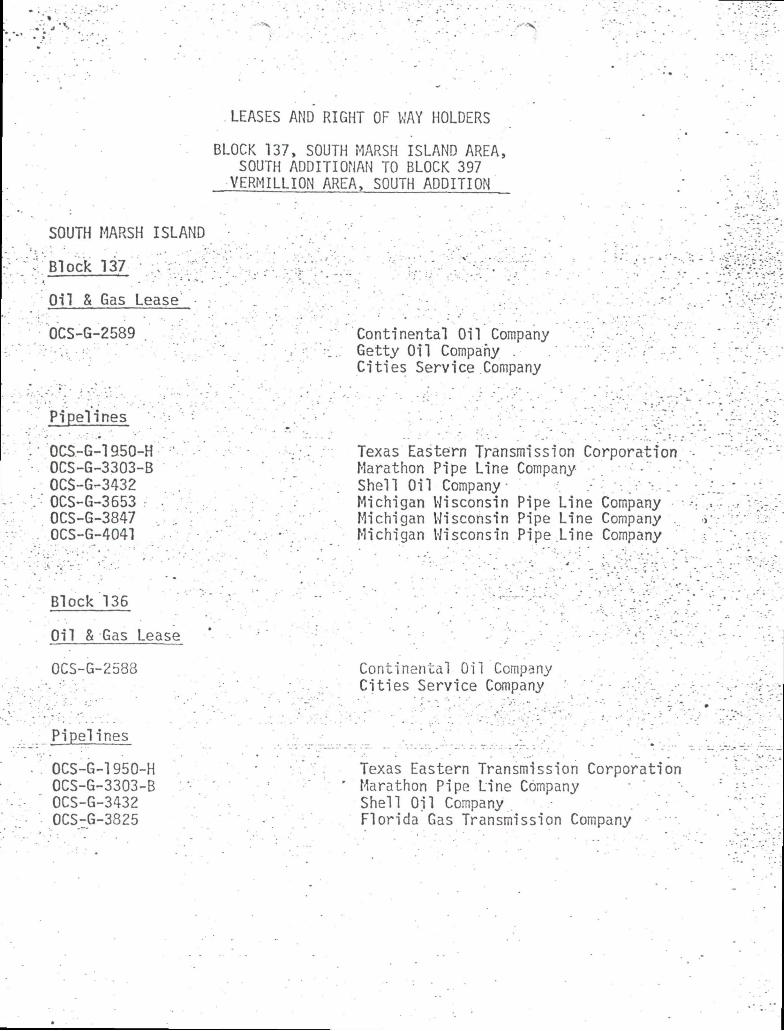
LEASES AND RIGHT OF WAY HOLDERS
BLOCK 137, SOUTH MARSH ISLAND AREA, SOUTH ADDITIONAN TO BLOCK 397 VERMILLION AREA, SOUTH ADDITION
SOUTH MARSH ISLAND
Block 137 V:
Oil & Gas Lease ;
OCS-G-2589 . Continental Oil Company Getty Oil Company . Cities Service Company
Pipelines
0CS-G-1950-H 0CS-G-3303-B 0C$-G-3432 0CS-G-3553 : OCS-G-3847 0CS-G-4041
Texas Eastern Transmission Corporation Marathon Pipe Line Company-Shell Oil Company • Michigan Wisconsin Pipe Line Company Michigan Wisconsin Pipe Line Company ... Michigan Wisconsin Pipe.Line Company
Block 135
Oil & Gas Lease
OCS-G-2588 Continental Oil Company Cities Service Company
Pipelines
OCS-G-1950-H 0CS-G-3303-B OCS-G-3432 OCS-G-3825
Texas Eastern Transmission Corporation Marathon Pipe Line Company Shell Oil Company Florida Gas Transmission Company
• . - -
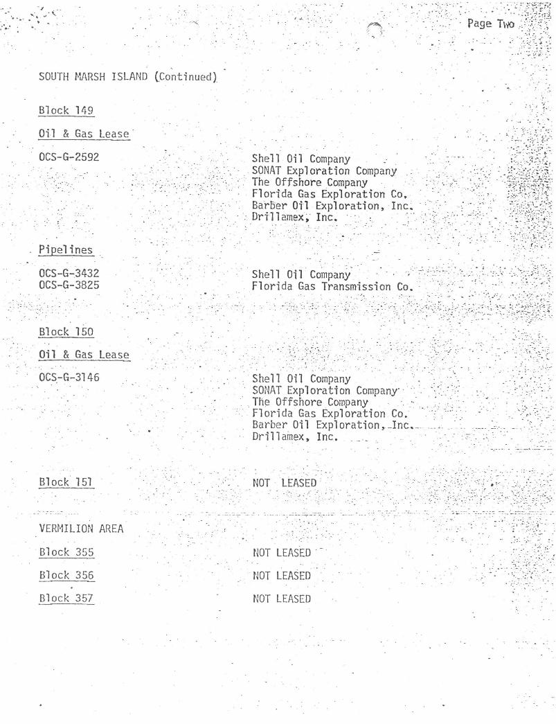
SOUTH MARSH ISLAND CContinued)
Page Two
•'• •* * -Block 149
Oil & Gas Lease
OCS-G-2592
Pipelines
OCS-G-3432 OCS-G-3825
Block 150
Oil S Gas Lease
0CS-G-3145
Shell Oil Company SONAT Exploration Company :. The Offshore Company Florida Gas Exploration Co, Barber Oil Exploration, Inc. Drillamex, Inc. • :
Shell Oil Company . • Florida Gas Transmission Co.
Shell Oil Company SONAT Exploration Company ' The Offshore Company ••' Florida Gas Exploration Co. Barber Oil Exploration,-Inc. Drillamex, Inc. ...
Block 151 NOT LEASED •
VERMILION AREA
Block 355
Block 355
Block 357
NOT LEASED
NOT LEASED
NOT LEASED
-1 .
' •^ . •1: i 'V -
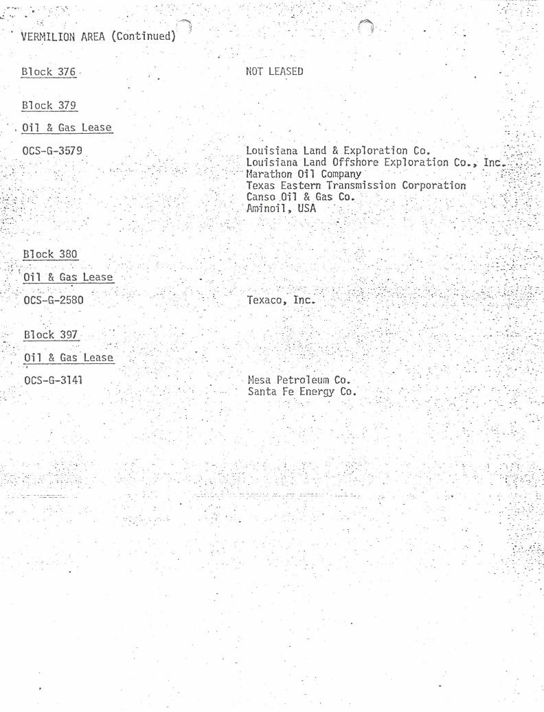
* VERMILION AREA (Continued)
Block 376 NOT LEASED
Block 379
Oil & Gas Lease
0C5-G-3579 Louisiana Land & Exploration Co. '."i/l---Louisiana Land Offshore Exploration Co., Inc^-%^>: Marathon Oil Company \ •• .^Wi--Texas Eastern Transmission Corporation v -v̂ .-. Canso Oil & Gas Co. •.• ̂ ; Ami noil, USA : ^ '[••'-•}:•
Block 380
Oil & Gas Lease
: OCS-G-2580 Texaco, Inc.
Block 397
Oil & Gas Lease
OCS-G-3141 Mesa Petroleum Co. Santa Fe Energy Co.
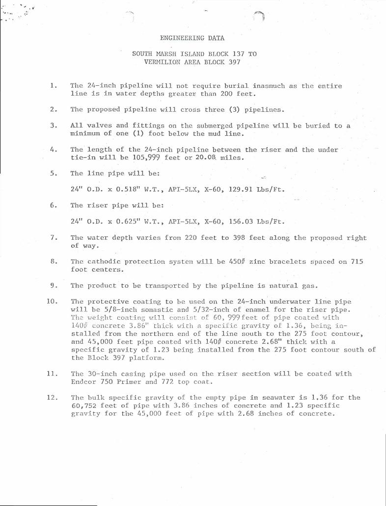
ENGINEERING DATA
SOUTH MARSH ISLAND BLOCK 137 TO VERMILION AREA BLOCK 397
1. The 24-inch pipeline w i l l not require b u r i a l inasmuch as the e n t i r e l i n e i s i n water depths greater than 200 fee t .
2. The proposed pipeline w i l l cross three (3) pipelines.
3. A l l valves and f i t t i n g s on the submerged pipe l i n e w i l l be buried to a minimum of one (1) foot below the mud l i n e .
4. The length of the 24-inch pipeline between the r i s e r and the under t i e - i n w i l l be 105,999 feet or 20.08. miles.
5. The l i n e pipe w i l l be:
24" O.D. x 0.518" W.T., API-5LX, X-60, 129.91 Lbs/Ft.
6. The r i s e r pipe w i l l be:
24" O.D. x 0.625" W.T., API-5LX, X-60, 156.03 Lbs/Ft.
7. The water depth varies from 220 feet to 398 feet along the proposed r i g h t of way.
8. The cathodic protection system w i l l be 450# zinc bracelets spaced on 715 foot centers.
9. The product to be transported by the pipeline i s n a t u r a l gas.
10. The p r o t e c t i v e coating to be used on the 24-inch underwater l i n e pipe w i l l be 5/8-inch somastic and 5/32-inch of enamel f o r the r i s e r pipe. The weight coating w i l l consist of 60, 999 feet of pipe coated with 140// concrete 3.86" thick with a speci f i c g r a v i t y of 1.36, being i n s t a l l e d from the northern end of the l i n e south to the 275 foot contour, and 45,000 feet pipe coated xjith 140// concrete 2.68" t h i c k w i t h a s p e c i f i c g r a v i t y of 1.23 being i n s t a l l e d from the 275 foot contour south of the Block 397 platform.
11. The 30-inch casing pipe used on the r i s e r section w i l l be coated w i t h Endcor 750 Primer and 772 top coat.
12. The bulk s p e c i f i c g r a v i t y of the empty pipe i n seawater i s 1,36 f o r the 60,752 feet of pipe with 3.86 inches of concrete and 1.23 sp e c i f i c g r a v i t y f o r the 45,000 feet of pipe with 2.68 inches of concrete.
ENGINEERING DATA BK. 137, SOUTH MARSH TO BK. 397, VER. AREA (Continued) Page 2
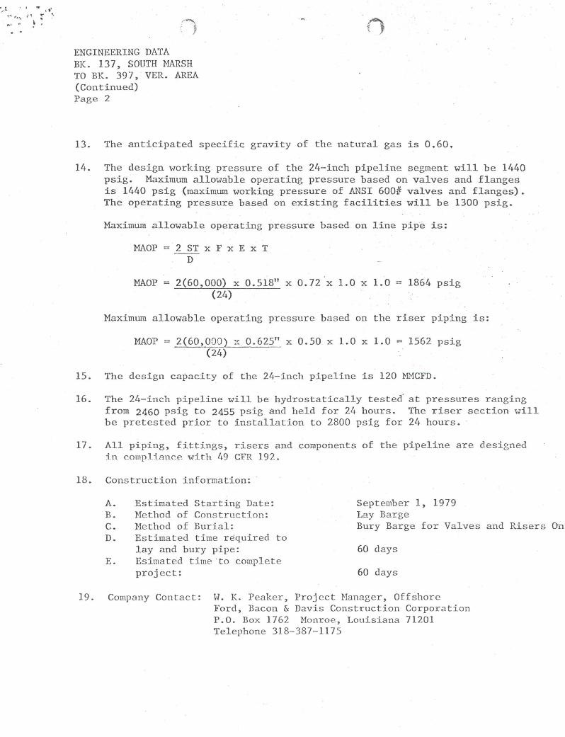
13. The anticipated s p e c i f i c g r a v i t y of the natural gas i s 0.60,
14. The design working pressure of the 24-inch pip e l i n e segment w i l l be 1440 psig. Maximum allowable operating pressure based on valves and flanges i s 1440 psig (maximum working pressure of ANSI 600# valves and flanges) . The operating pressure based on e x i s t i n g f a c i l i t i e s w i l l be 1300 psig.
Maximum allowable operating pressure based on l i n e pipe i s :
MAOP = 2 ST x F x E x T D
MAOP = 2(60,000) x 0.518" x 0.72 x 1.0 x 1.0 = 1864 psig (24)
Maximum allowable operating pressure based on the r i s e r piping i s :
MAOP = 2(60,000) x 0.625" x 0.50 x 1.0 x 1.0 = 1562 psig (24)
15. The design capacity of the 24-inch pipeline i s 120 MMCFD.
16. The 24-inch pip e l i n e w i l l be h y d r o s t a t i c a l l y tested at pressures ranging from 2460 psig to 2455 psig and held f o r 24 hours. The r i s e r section w i l l be pretested p r i o r to i n s t a l l a t i o n to 2800 psig f o r 24 hours.
17. A l l pi p i n g , f i t t i n g s , r i s e r s and components of the p i p e l i n e are designed i n compliance w i t h 49 CFR 192.
18. Construction information:
A. Estimated Starting Date: September 1, 1979 B. Method of Construction: Lay Barge C. Method of B u r i a l : Bury Barge f o r Valves and Risers On D. Estimated time required to
lay and bury pipe: 60 days E. Esimated time to complete
p r o j e c t : 60 days
19. Company Contact: W. K. Peaker, Project Manager, Offshore Ford, Bacon & Davis Construction Corporation P.O. Box 1762 Monroe, Louisiana 71201 Telephone 318-387-1175