michigan department of transportation · specifications, 2012 (aashto design), aashto’s lrfd...
TRANSCRIPT

Field Manual for Structural Bolting
Prepared By
Bridges and Structures Research Center of
Excellence
MDOT
Bridge Field Services
Michigan Department of Transportation

1st Edition - April 2014
Table of Contents Glossary .............................................................................................................. 3
Equivalent ASTM and AASHTO Standard Specifications ..................................... 5
Acknowledgement .............................................................................................. 6
Introduction and Purpose ................................................................................... 7
Governing Specifications .................................................................................... 7
Part I - High Strength Bolt (HSB) Connections ...................................................... 9
General Considerations for HSB Connections..................................................... 9
Bolt Assembly ................................................................................................ 9
Types of HSB Joints ........................................................................................ 9
ASTM Bolt Types .......................................................................................... 11
Washers ....................................................................................................... 12
Nuts ............................................................................................................. 12
Bolt Holes ..................................................................................................... 13
Faying Surface for Slip-Critical Connections ................................................. 13
Installation Considerations and Techniques ..................................................... 14
Snug Tight Bolt Installation .......................................................................... 14
Turn of the Nut Installation .......................................................................... 15
Calibrated Wrench Method .......................................................................... 15
Direct Tension Indicators ............................................................................. 15
Installation Procedures .................................................................................... 21
Shipping of Fasteners ................................................................................... 21
Storage of Fasteners .................................................................................... 21
Fastener Paperwork ..................................................................................... 21
MDOT Specific Certification Documentation ................................................ 22
Tagging and Marking Material Status ........................................................... 23
Field Manual for Structural Bolting 1

Pre-Test Documentation .............................................................................. 24
MDOT Material Acceptance Requirements .................................................. 24
Pre-Bolting Inspection .................................................................................. 24
Rotational-Capacity Test .............................................................................. 25
Rotational-Capacity Test Procedure ............................................................. 26
General Installation Requirements ............................................................... 29
Inspection Tasks during and after Bolting .................................................... 30
Part 2 – Anchor Bolt (AB) Connections .............................................................. 32
Types of AB Connections .................................................................................. 32
Anchor Bolt Materials ...................................................................................... 33
Cantilever and Truss Sign Supports, Light Standards, Dynamic Message Sign Structures and CCTV Poles, Tower Lighting Units and Mast Signal Arm Supports ....................................................................................................... 34
Traffic Signal Strain Poles ............................................................................. 35
Other Purposes ............................................................................................ 36
Base Plate and Anchor Bolt Holes .................................................................... 36
General Installation Requirements................................................................... 37
Anchor Bolt Pretensioning ............................................................................... 37
Common Deficiencies ...................................................................................... 40
MDOT Bridge Field Services – Contact Information ........................................... 45
Field Manual for Structural Bolting 2

Glossary Coated Faying Surface. A faying surface that has been primed, primed and painted, or protected against corrosion, except by hot-dip galvanizing.
Connection. An assembly of one or more joints that is used to transmit forces between two or more members.
Direct Tension Indicators. Direct tension indicators (DTIs) are special washers with raised protrusions on one face which compress when the bolt is tightened. They are used for verifying proper tensioning without relying on turn of the nut markings.
Faying Surface. The plane of contact between two plies of a joint.
Firm Contact. The condition that exists on a faying surface when the plies are solidly seated against each other, but not necessarily in continuous contact.
Galvanized Faying Surface. A faying surface that has been hot-dip galvanized.
Grip. The total thickness of the plies of a joint through which the bolt passes, exclusive of washers or direct-tension indicators.
High-Strength Bolt. An ASTM A325, A449, or A490 bolt, an ASTM F1852 or F2280 twistoff-type tension-control bolt or an alternative-design fastener.
Joint. A bolted assembly with or without collateral materials that is used to join two structural elements.
Pretensioned Joint. A joint that transmits shear and/or tensile loads in which the bolts have been installed to provide a pretension in the installed bolt.
Rotational-Capacity Test. Rotational-capacity tests are intended to document the relationship between torque and pretension and ensure that the bolts can develop the necessary pretension without undergoing failure. They are performed by the bolt manufacturer and MDOT Metals Lab prior to incorporation and are carried out in accordance with ASTM A325. These tests are conducted in a Skidmore-Wilhelm Bolt Tension Calibrator.
Field Manual for Structural Bolting 3
Shear/Bearing Joint. A snug-tightened joint or pretensioned joint with bolts that transmit shear loads and for which the design criteria are based upon the shear strength of the bolts and the bearing strength of the connected materials.
Skidmore-Wilhelm Bolt Tension Calibrator. Commonly known as a Skidmore, it is the device for developing torque-tension relationships. It should be calibrated annually by a certified lab.
Slip-Critical Joint. A joint that transmits shear loads or shear loads in combination with tensile loads in which the bolts have been installed to provide a pretension in the installed bolt (clamping force on the faying surfaces), and with faying surfaces that have been prepared to provide a calculable resistance against slip.
Snug Tight. Snug tight condition is defined as the full effort of a typical person as applied using an ordinary spud wrench. A bolt in snug tight condition will carry no less than 10% of its pretension load. Snug tight conditions can also be achieved with a few impacts of an impact wrench.
Standoff Distance. Standoff distance of anchor bolts in structural supports for highway signs, luminaires, and traffic signals refers to the clearance between the bottom of the leveling nuts and the top of the concrete foundation. The maximum allowable standoff distance is one inch.
Tension Calibrator. A calibrated tension-indicating device that is used to verify the acceptability of the pretensioning method when a pretensioned joint or slip-critical joint is specified.
Turn-of-Nut. A technique for ensuring that the minimum pretensioning has been achieved. Turn-of-nut pretensioning involves holding one end of the bolt assembly (head or nut) and rotating the other end to achieve a specified rotation, which varies by bolt diameter and length.
Uncoated Faying Surface. A faying surface that has neither been primed, painted, nor galvanized and is free of loose scale, dirt and other foreign material.
Verification Testing. Prior to fastener installation, a representative sample of bolt assemblies must be checked in a device that indicates bolt tension. These tests should demonstrate that controlling the required turns from a snug tight
Field Manual for Structural Bolting 4

condition develops a tension no less than 5% greater than the required tension shown in Table 707-4 of the MDOT SSC.
Equivalent ASTM and AASHTO Standard Specifications The following are some common ASTM standard specifications and their AASHTO equivalents.
ASTM Title AASHTO Equivalent
A123
Standard Specification for Zinc (Hot-Dip Galvanized) Coatings on Iron and Steel Products
M111
A153
Standard Specification for Zinc Coating (Hot-Dip) on Iron and Steel Hardware
M232
A194 Standard Specification for Carbon and Alloy Steel Nuts for Bolts for High Pressure or High Temperature Service, or Both
M292
A325
Standard Specification for Structural Bolts, Steel, Heat Treated, 120/105 ksi Minimum Tensile Strength
M164 (discontinued)
A490
Standard Specification for Structural Bolts, Alloy Steel, Heat Treated, 150 ksi Minimum Tensile Strength
M253 (discontinued)
A563
Standard Specification for Carbon and Alloy Steel Nuts
M291 (discontinued)
F436
Standard Specification for Hardened Steel Washers
M293 (discontinued)
F1554
Standard Specification for Anchor Bolts, Steel, 36, 55, and 105-ksi Yield Strength
M314
Field Manual for Structural Bolting 5

Acknowledgement The material presented herein was put together by Sherif El-Tawil and Jason McCormick of the Department of Civil and Environmental Engineering at the University of Michigan (UM) under the auspices of the Michigan Department of Transportation (MDOT) funded UM Bridges and Structures Research Center of Excellence. The UM Center is directed by Sherif El-Tawil and managed by MDOT’s Steve Kahl and Michael Townley. Matt Filcek, Peter Jansson, Brion Klopf and Jeff Weiler, who are members of MDOT’s Bridge Field Services team, provided content and reviewed the material.
Content was taken from several sources including AASHTO’s LRFD Bridge Design Specifications, 2012 (AASHTO Design), AASHTO’s LRFD Bridge Construction Specifications, 2010 (AASHTO Construction), Michigan Department of Transportation’s Bridge Design Manual, 2012 (MDOT BDM), MDOT’s Standard Specifications for Construction, 2012 (MDOT SSC), the Specification for Structural Steel Joints using High Strength Steel Bolts by the Research Council on Structural Connection, 2009 (RCSC) and AASHTO’s Standard Specifications for Structural Supports for Highway Signs, Luminaires, and Traffic Signals, 2013 (AASHTO Signs).
Additional content was adapted from the Transportation Curriculum Coordination Council (TCCC) Bolted Connections course offered by the National Highway Institute (Course Number FHWA-NHI-134074) and American Institute of Steel Construction’s (AISC) Bolting and Welding Course (https://www.aisc.org/WorkArea/showcontent.aspx?id=37216).
Field Manual for Structural Bolting 6

Introduction and Purpose The purpose of this Field Manual for Structural Bolting is to summarize basic definitions, concepts and procedures for bolted connections. The Manual addresses general considerations for bolting, installation preparation, installation techniques and inspection procedures. The intent of the Manual is to assist engineers, inspectors and construction workers to design, install and inspect bolted connections to meet current specifications. The primary function of bolted connections is to join or anchor structural members and safely transmit loads from one member to the other or to a foundation. As such, bolted connections are critical components of any structure. For many types of structural systems, failure of a bolted connection could lead to collapse or extensive system-wide damage. Therefore, current design specifications and construction procedures impose rigorous design, installation and inspection practices to ensure that such connections are able to perform their function safely. Structural connections may be subjected to multiple types of forces including flexure, shear, axial, torsional, or a combination of these forces. Bolts can transmit shear, axial or combined shear/axial loads. Therefore, bolted connections, regardless of how they are loaded, are configured and designed such that bolts are loaded to resist shear and axial loads.
Governing Specifications The design of highway bridges in Michigan is based on AASHTO Design. The construction and fabrication of highway bridges is based on the published AASHTO Construction. The design of supports for road side hardware is governed by AASHTO Signs. In some cases, the AASHTO specifications are vague or leave a decision to the judgment of the Engineer. Guidelines in the MDOT BDM are provided as clarification and thus supplement the AASHTO provisions. Some minimum requirements in the AASHTO specifications have been found through experience to be insufficient. In these instances, the MDOT BDM supersedes AASHTO with more rigorous controls. The Research Council on Structural Connections prepares specifications and documents related to structural connections. RCSC is a widely used specification
Field Manual for Structural Bolting 7

which discusses joints, fasteners, limit states, installation, and inspections. AASHTO adopts (with modifications) some of the RCSC recommendations. The MDOT SSC is the standard for basic requirements governing materials, equipment and methods used in construction contracts administered by MDOT. MBDM will primarily reference AASHTO specifications. SSC is for construction and does not reference the MBDM. Any references within SSC usually pertain to ASTM or AASHTO material specs, and other subsections within itself. Figure 1 shows the various standards mentioned.
Figure 1: Standards used for preparation of this Manual.
Michigan Department of Transportation
AASHTO LRFD Bridge Design Specifications
(AASHTO Design)
MDOT’s Michigan Bridge Design
Manual(MDOT BDM)
MDOT’s Standard Specifications for
Construction(MDOT SSC)
Research Council on Structural Connections
(RCSC)
Standard Specifications for Structural Supports for
Highway Signs, Luminaires, and Traffic
Signals (AASHTO Signs)
AASHTO LRFD Bridge Construction
Specifications(AASHTO
Construction)
Field Manual for Structural Bolting 8

Part I - High Strength Bolt (HSB) Connections
General Considerations for HSB Connections
Bolt Assembly Figure 2 shows the main parts of the bolt assembly. Grip is the distance from behind the bolt head to the back of the nut or washer. It is the sum of the thicknesses of all the parts being joined exclusive of washers. Thread length is the threaded portion of the bolt. Bolt length is the distance from behind the bolt head to the end of the bolt.
Figure 2: Bolt assembly components.
Types of HSB Joints There are two basic load transfer mechanisms in bolted joints: bearing and slip critical.
Bearing Joints: Load is transferred between components by bearing on the bolts. This can be seen in Figure 3, where the two bolted plates bear against the shank (and threads) of the bolt, which then transmits load between them. Note that MDOT does not permit bolted connections with threads included unless explicitly called out in the contract plans.
HeadShank
WasherNutWasher
Face
Grip
Thread
Length
Field Manual for Structural Bolting 9

Slip-critical Joints: Load is transferred between components by friction between the bolted components (Figure 4). The bolts are fully pretensioned to cause a clamping force between the connected components, which allows frictional resistance to develop between them. The frictional resistance prevents the connected components from slipping into bearing against the body of the bolt. However, the bolts must still be designed for bearing for strength loads since slip-critical joints are only designed for service conditions. To ensure successful performance, the faying surfaces in slip-critical joints require special preparation. The vast majority of MDOT’s bolted bridge connections are slip critical.
Figure 3: Load transmission in a bearing-type connection.
Figure 4: Load transmission in a slip critical-type connection (bolt pretension prevents slip into bearing for service loads).
Bearing forces
Friction forces
Faying surface
Bolt pretension
Bolt pretension
Field Manual for Structural Bolting 10

ASTM Bolt Types There are two types of high strength bolts, A325 and A490, defined as follows.
A325 Bolts [also known as M164 Bolts]. These bolts have a tensile strength of 90 ksi on up. They are made of heat treated, medium carbon steel and are the most common bolts used by MDOT. The minimum tensile strength is 120 ksi for diameters 0.5 through 1.0 in and 105 ksi for diameters 1.125 through 1.5 in.
A490 Bolts [also known as M253 Bolts]. These bolts are made of high-strength, heat treated steel with a minimum tensile strength of 150 ksi. A490 bolts cannot be hot-dip galvanized due to hydrogen embrittlement; therefore, they are not used for bridges or other highway structures and are not permitted by MDOT.
ASTM designation is indicated on the head of the bolts as shown in Figure 5.
A325 bolts are available in diameters ranging from 1/2” to 1-1/2”. However, all structural bolts must be at least 0.625” in diameter. The most common sizes are 3/4”, 7/8”, and 1”. High-strength bolts are commonly available in incremental lengths up to 8”.
Figure 5: ASTM designation on bolt heads.
Field Manual for Structural Bolting 11

Washers Hardened steel washers (Figure 6) are used to spread pressure from the bolt tightening process over a larger area. They may also be used to cover an oversized or slotted hole. ASTM F436 Flat washers are most commonly used. Tapered washers (Figure 7) are used when the surface being bolted has a sloped surface, such as the flange of a channel or an S shape or out-of-plumb anchor bolts.
Figure 6: Washers. Figure 7: Tapered washers.
For pretensioned joints, A325 bolts require a washer under the element (head or nut) being turned to tighten the bolt. For pretensioned joints with specified base metal yield strength less than 40ksi, A490 and F2280 bolts require a washer under both the head and nut.
High-strength washers for structural joints must meet the requirements of AASHTO M 293 Type 1 for circular, beveled, clipped circular, and clipped beveled washers. Washers must be hot dip galvanized in accordance with AASHTO M 232.
Hardened washers should be installed over oversize and short-slotted holes in an outer ply. Structural plate washers are required to completely cover long-slotted holes (see Figure 8).
Washer use is encouraged by MDOT even if not required by specifications.
Nuts High-strength nuts for structural joints must meet the requirements of AASHTO M 291 Grade DH or AASHTO M 292 Grade 2H.
Field Manual for Structural Bolting 12

Nuts must be hot dip galvanized in accordance with AASHTO M 232. Galvanized nuts must be tapped oversize in accordance with AASHTO M 291 and must be coated with a lubricant containing a visible dye.
Bolt Holes There are four types of holes: standard (STD), oversize (OVS), short Slot (SSL) and long Slot (LSL) – see Figure 8. Unless otherwise specified, only STD holes should be used in bridge construction in Michigan, unless explicitly approved by the Engineer.
Allowed tolerances for hole diameter are 1/32”. Burrs which prevent solid seating of connected parts in the snug-tight condition must be removed by reaming or light grinding. Note that recoating is required after grinding. Connections with holes exceeding the specified tolerances must be replaced unless approved by the Engineer.
Figure 8: Bolt hole types.
Faying Surface for Slip-Critical Connections Faying surfaces are surfaces placed in contact during bolting operations (see Figure 4) and include the surfaces beneath the bolt head, nut and/washer. All joint surfaces (including surfaces adjacent to the bolt head and nut) must be: 1) non compressible material, 2) free of scale except tight mill scale, and 3) free of dirt and foreign material. Joint surfaces should be inspected prior to lifting the
Bolt Shank
STD OVS
SSL LSL
Field Manual for Structural Bolting 13

steel component into its final location. As shown in Figure 9, there are 3 classes of faying surfaces depending on preparation.
Class A Class B Class C • Least amount of
friction resistance. • Unpainted, clean
mill scale. • Blast cleaned
surface with Class A coating.
• Slip coefficient = 0.33.
• This type of faying surface is not permitted by MDOT.
• Unpainted, blast cleaned surfaces
• Blast cleaned surface with Class B coating
• Slip coefficient = 0.50
• Hot dipped galvanized surface
• Roughened by wire brushing (not power wire brush) after galvanizing
• Slip coefficient = 0.33 per AASHTO (= 0.35 per RCSC)
• This type of faying surface is not permitted by MDOT.
Figure 9: Types of faying surfaces and their characteristics.
Installation Considerations and Techniques
Snug Tight Bolt Installation Snug tight condition is defined as the full effort of a typical person as applied using an ordinary spud wrench (Figure 10). A bolt in snug tight condition will carry no less than 10% of its pretension load. Snug tight conditions can also be achieved with a few impacts of an impact wrench.
Figure 10: Spud wrenches.
Field Manual for Structural Bolting 14

Turn of the Nut Installation Installation beyond snug-tight is called pretensioning. Prior to fastener installation, a representative sample of not less than three bolt, nut and washer assemblies of each diameter and bolt length specified in Table 707-5 of the MDOT SSC must be checked in a device that indicates bolt tension. These tests should demonstrate that controlling the required turns from a snug tight condition develops a tension no less than 5% greater than the required tension shown in Table 707-4 of the MDOT SSC. This is known as bolt verification testing.
Turn-of-nut pretensioning involves the following steps:
• Ensure that tight iron has been achieved. • The bolt is snug-tightened. • Match marks are placed on each nut, bolt, and steel surface in a straight
line (Figure 11). • The part not turned by the wrench is prevented from turning. • The bolt is tightened with a prescribed rotation past the snug-tight
condition. • The specified rotation varies by diameter and length (between 1/3 and 1
full turn).
Calibrated Wrench Method This technique is not permitted by MDOT.
Direct Tension Indicators Direct tension indicators (DTIs) are special washers with raised protrusions (Figure 12) on one face which compress when the bolt is tightened. They are a method for verifying proper tensioning without relying on turn of the nut markings. They are identified by material specification and manufacturer.
Verification tension is 105% of the pretension for the bolt. Three verification tests are required for each:
• Rotational-Capacity lot • DTI log • DTI position within the assembly
Field Manual for Structural Bolting 15

Figure 11: Turn of the nut procedure.
Field Manual for Structural Bolting 16

Figure 12: A direct tension indicator washer.
Tests are performed in a calibrated bolt tension measuring device (Skidmore-Wilhelm). DTIs pass verification testing when the requisite number of gaps refuse a 0.005 in. feeler gage (Figure 13). DTIs have to be placed in certain locations as shown in Figure 14.
Installation of DTIs occur in two stages after all plies of the connections are in firm contact.
Stage 1 – Snug Tight
• Snug connection with bolts installed in all holes. • Tension sufficiently so that all plies of the connection are in firm contact. • Ensure refusals with a 0.005 in. feeler gage meet the Maximum Refusal
requirements during verification testing (Table 1). • If exceed maximum value then remove and replace DTI.
Stage 2- Pretension
• For coated DTI (only type permitted by MDOT) under a stationary element, tension the bolt until the number of refusals with a 0.005 in. feeler gage is equal to or greater than the Minimum Installation Refusals outlined in Table 2.
• For coated DTI (only type permitted by MDOT) under a turned element, a 0.005 in. feeler gage should be refused in all spaces (Table 2).
• If there is no visible gap, remove and replace the bolt and DTI.
Failure at any stage requires removal and replacement of DTI. A visible gap should remain (See Figure 15).
Field Manual for Structural Bolting 17

Figure 13: Feeler gage.
Table 1: Maximum verification refusals for DTIs.
Bolt Diameter
(in.)
DTI Spaces
Maximum Verification Refusals (DTI under Stationary
Element)
Maximum Verification Refusals (DTI under Turned
Element) ASTM A325
ASTM A490
ASTM A325
ASTM A490
ASTM A325
ASTM A490
5/8 4 5 1 2 3 4 3/4 5 6 2 2 4 5 7/8 5 6 2 2 4 5 1 6 7 2 3 5 6
1-1/8 6 7 2 3 5 6 1-1/4 7 8 3 3 6 7 1-3/8 7 8 3 3 6 7 1-1/2 8 9 3 4 7 8
Test gap = 0.005”
Field Manual for Structural Bolting 18

Table 2: Minimum Installation Refusals for DTIs
Bolt Diameter
(in.)
DTI Spaces
Minimum Installation Refusals
(DTI under Stationary Element)
Minimum Installation Refusals
(DTI under Turned Element)
ASTM A325
ASTM A490
ASTM A325
ASTM A490
ASTM A325
ASTM A490
5/8 4 5 2 3 4 5 3/4 5 6 3 3 5 6 7/8 5 6 3 3 5 6 1 6 7 3 4 6 7
1-1/8 6 7 3 4 6 7 1-1/4 7 8 4 4 7 8 1-3/8 7 8 4 4 7 8 1-1/2 8 9 4 5 8 9
Figure 14: Location of DTI in bolt assembly.
Field Manual for Structural Bolting 19

Note: Nut is the turned element.
Figure 14 (continued): Location of DTI in bolt assembly.
Figure 15: Visible gap at DTI remains after tensioning.
Field Manual for Structural Bolting 20

Installation Procedures
Shipping of Fasteners Bolts, loose nuts, and washers of each length, diameter, or size should be packed separately. Storage and shipping should be done in moisture proof boxes, crates, kegs, or barrels. The gross weight of each package is limited to 300 lbs. Contents should be labeled on the outside of the shipping container. Supply 5% more high strength bolts of each size and length than required for the job
Nuts of galvanized fasteners must be lubricated with a clean and dry material to the touch (wax) that contains a visible dye.
Storage of Fasteners Fastener components must be protected from dirt and moisture in closed containers (Figure 16). Only the number of fasteners required to be installed and tightened during a working shift should be removed from storage. Unused fasteners should be returned to protected storage at the end of a shift. Lubricant should not be removed.
Visible corrosion is a cause for rejection.
Figure 16: Storage of fasteners.
Fastener Paperwork Documents with each bolt shipment become part of the construction record. These include: packing list with each shipment of bolts, other documents, and test
Field Manual for Structural Bolting 21

reports [mill test report (MTR), manufacturer certified test report (MCTR), distributor certified test report (DCTR)].
Paperwork for any lot of bolts, nuts and washers should be maintained. Container information should be checked to ensure it matches the provided paperwork (see Figure 17). The packing list should contain the following information:
• Verification of Buy America provisions • Detailed list of all fastener assemblies • Manufacturer’s and Supplier’s Name • Shipment item • Bolt size and grade • Bolt, nut and washer lot number • Coating data • Quantity
Important: Mixing bolts and nuts from different production lots is not permitted.
Figure 17: Type of information found on container.
MDOT Specific Certification Documentation General Certification Documents must include all of the following:
• List of all applicable specifications (ASTM, AASHTO, MDOT, etc.) that the material is certified to meet
Field Manual for Structural Bolting 22
• Any specification modifiers (class, grade, type, etc.) • Signed statement by representative of the manufacturer or supplier that
material meets all MDOT listed specification requirements • Manufacturer’s name on certification if certified by supplier • Contract number (Control Section/Job Number)
• Date of Shipment
• Name of Contractor
• Name of Material (MDOT designation Spec No. – High Strength Bolts 906.07)
• Identification markings on shipment
• Quantity of material represented by the certification
Test Data Certification Documents must include:
• Laboratory test reports for samples obtained from the lot(s) of material represented by the certification and tested according to applicable specifications (ASTM, AASHTO, MDOT, etc.)
Tagging and Marking Material Status Methods for informing the status of sampling and/or testing of bolts in storage include:
• Numbered Tags
– Metallic locking type tags “deer tags”
– Indicate samples have been taken but does not mean they have been approved
• Sampled Tags (or Stickers)
– Yellowish-green colored wire-on tags
– Yellowish-green pressure sensitive tags without the wire tie
• Approval Tags (or Stickers)
Field Manual for Structural Bolting 23

– Red wire-on tags with the word approved and space for the sampler’s name or initial, date, and project number
– Red pressure sensitive tags without the wire tie
• MDOT Approval stamp, “M” Hammer Mark, Orange “M”
Pre-Test Documentation Material Source List (MDOT Form 501)
• Required project documentation
• Not a substitute for other required quality control and quality assurance documentation
• Responsibility of the prime contractor to submit at or prior to the preconstruction meeting
MDOT Material Acceptance Requirements Testing is required as follows: 1 per diameter per length per heat per project. The sample size is 3 each of bolt, nut and washer.
Bolt, nut and washer Test Data Certification must identify the manufacturer and must be attached to the Sample ID (MDOT Form 1923).
Pre-Bolting Inspection Pre-bolting inspection ensures minimum requirements for quality control and quality assurance.
Observation is the primary method used to confirm that the materials, procedures and workmanship are in conformance with the construction documents and specifications. Table 3 shows typical tasks considered.
Field Manual for Structural Bolting 24
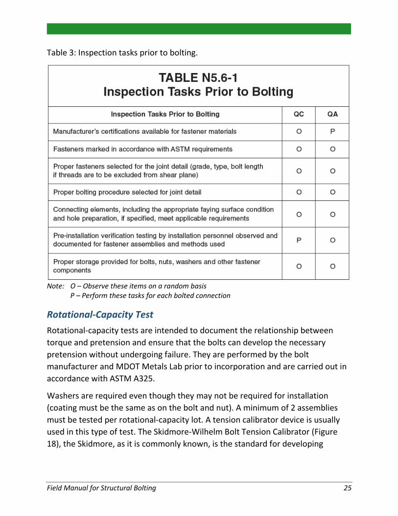
Table 3: Inspection tasks prior to bolting.
Note: O – Observe these items on a random basis
P – Perform these tasks for each bolted connection
Rotational-Capacity Test Rotational-capacity tests are intended to document the relationship between torque and pretension and ensure that the bolts can develop the necessary pretension without undergoing failure. They are performed by the bolt manufacturer and MDOT Metals Lab prior to incorporation and are carried out in accordance with ASTM A325.
Washers are required even though they may not be required for installation (coating must be the same as on the bolt and nut). A minimum of 2 assemblies must be tested per rotational-capacity lot. A tension calibrator device is usually used in this type of test. The Skidmore-Wilhelm Bolt Tension Calibrator (Figure 18), the Skidmore, as it is commonly known, is the standard for developing
Field Manual for Structural Bolting 25

torque-tension relationships and should be on any jobsite. It should be calibrated annually by a certified lab.
Rotational-Capacity Test Procedure A rotational-capacity test is conducted as follows:
• Select 2 bolt, nut and washer assemblies for each rotational-capacity lot • Install bolt, nut and washer with additional face plates and shims to achieve
3-5 threads in grip (Figure 19) • Initially tighten the nut to not less than 10% of the minimum required
tension (snug-tight) • After initial tightening, the nut position shall be marked relative to the bolt,
and the rotation shown in Figure 20 shall be applied. The nut can be tightened with a torque wrench or air wrench. During rotation, the bolt head shall be restrained from turning.
• Rotation values will be 2 times the values used during turn of the nut. Minimum tension in the bolt at the specified rotation shall be equal to or greater than 1.15 times the minimum required installation tension.
• Indicated rotations shall not cause stripping or failure (Figures 21 and 22) • Record one reading of tension and torque after exceeding the minimum
required installation tension. Torque shall not exceed:
• Remove and examine the bolt and nut (Figures 21 and 22) for:
o Thread stripping
o Shearing of threads
o Torsional failure
• Check to see if the nut still turns freely • Elongation of the bolt in the threads is not classified as failure
Max Allowable Torque(ft.-lbs)
Measured Bolt Tension(lbs.)
Bolt Diameter (ft.)
Field Manual for Structural Bolting 26
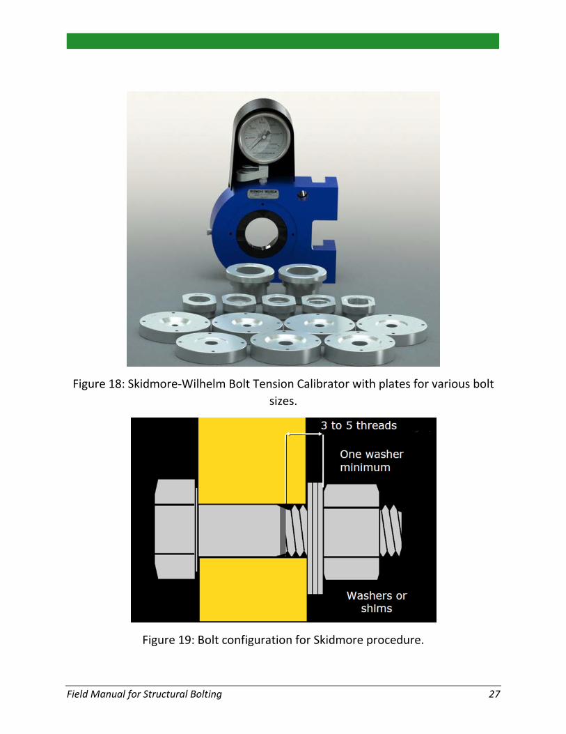
Figure 18: Skidmore-Wilhelm Bolt Tension Calibrator with plates for various bolt sizes.
Figure 19: Bolt configuration for Skidmore procedure.
Field Manual for Structural Bolting 27

Figure 20: Rotation for Skidmore procedure (D=bolt diameter, L=bolt length)
Figure 21: Failure modes to look for after Skidmore procedure.
(a) Torsional Failure (b) Tension Failure
Figure 22: Bolt failure in torsion versus tension.
Field Manual for Structural Bolting 28
General Installation Requirements Fastener assemblies must be protected from dirt and moisture. Components should not be cleaned of lubricant as received. Galvanized nuts should have visible lubricant. Moreover, if fastener condition changes (corrosion or removal of lubricant), rotation-capacity tests need to be redone. Also, faying surfaces must be properly treated.
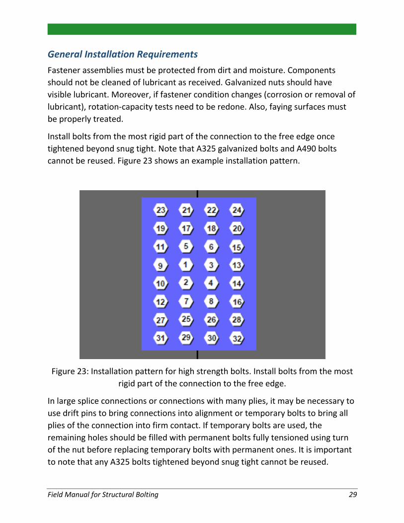
Install bolts from the most rigid part of the connection to the free edge once tightened beyond snug tight. Note that A325 galvanized bolts and A490 bolts cannot be reused. Figure 23 shows an example installation pattern.
Figure 23: Installation pattern for high strength bolts. Install bolts from the most rigid part of the connection to the free edge.
In large splice connections or connections with many plies, it may be necessary to use drift pins to bring connections into alignment or temporary bolts to bring all plies of the connection into firm contact. If temporary bolts are used, the remaining holes should be filled with permanent bolts fully tensioned using turn of the nut before replacing temporary bolts with permanent ones. It is important to note that any A325 bolts tightened beyond snug tight cannot be reused.
Field Manual for Structural Bolting 29
Inspection Tasks during and after Bolting Snug-tightened joints require visual inspection for firm contact and proper use of washers. Pretensioned joints require pre-installation verification and routine observation of proper application. Slip-critical joints require inspection of the faying surfaces in addition to the above inspections. There are several bolted connection inspections that can be performed:
• Look at the bolt stick-out (Figure 24)
• Stick-out is the amount the bolt extends beyond the outside surface of the nut
• Positive or zero stick-out is acceptable • Negative stick-out, where the end of the bolt is inside the nut
is not acceptable • Stick-out on bottom flange field splices must be on top of
bottom flange (bolt head on bottom side of bottom flange)
• Inspect the turn-of-nut match marks to ensure the bolts have been pretensioned (Figure 25)
• Note that corrosion is cause for rejection
Field Manual for Structural Bolting 30

Figure 24: Acceptable bolt stick out.
Figure 25: Inspect the turn-of-nut match marks to ensure the bolts have been properly pretensioned.
Field Manual for Structural Bolting 31

Part 2 – Anchor Bolt (AB) Connections
Types of AB Connections AB connections are designed to transmit tension, bearing and shear forces, associated with highway structures, into a concrete support or foundation. These types of connections use cast-in-place anchor bolts in new construction. Although the anchor bolts may be headed, hooked or deformed reinforcing bars, headed are generally preferred. There are two types of AB connections: single-nut and double-nut connections.
Figure 26 shows a single nut AB connection. These types of joints are also known as threaded-shear–uplift joints. In such connections, the base plate rests directly on a concrete or grout pad. The anchor bolts transmit shear and tension, while the concrete carries all compression forces. Therefore, the grout support must achieve full strength prior to pretensioning. The connection does not require leveling nuts or shim plates. This type of connection has some structural disadvantages and is not permitted by MDOT.
Figure 26: Typical single-nut AB connection (not permitted by MDOT).
Field Manual for Structural Bolting 32

Figure 27 shows a double-nut AB connection. In these connections, pretension exists between the upper nuts and corresponding leveling nuts. MDOT does not allow grout to be placed below the base plate of double-nut connections. AASHTO requires a minimum of six anchor bolts for highway structures with the exception of a minimum of eight anchor bolts required for high mast luminaires.
Figure 27: Typical double-nut AB connection.
Anchor Bolt Materials Headed and hooked anchor bolts (Figure 28) provide anchorage to concrete. Note that MDOT prefers the use of headed anchor bolts and highway structure designs are being revised to reflect this. Unless otherwise stated, anchor bolt material must meet the requirements of ASTM F1554. Hooked smooth bars require a maximum yield strength of 55 ksi, whereas headed anchor bolts utilize 36, 55 and 105 ksi material.
The supplier must provide test data certification for anchor bolts with a reference to heat number of steel. The test results should include yield strength, tensile strength, elongation, reduction of area and Charpy V-notch.
STANDOFF DISTANCE
Field Manual for Structural Bolting 33

Cantilever and Truss Sign Supports, Light Standards, Dynamic Message Sign Structures and CCTV Poles, Tower Lighting Units and Mast Signal Arm Supports Anchor bolts must be medium carbon hot rolled steel bar that meets the requirements of ASTM F1554 Gr. 55. Notch toughness tests must be performed in accordance with Test Frequency (P) Piece Testing of AASHTO T243. The exposed threaded ends of anchor bolts must be hot-dipped galvanized a minimum of 20 in in accordance with ASTM A 153. Anchor bolt threads must meet the requirements of ANSI B1.1, for 8UN series, Class 2A tolerances prior to coating. After coating, the maximum limit of pitch and major diameter for bolts may exceed the Class 2A limit by no greater than 0.021 in. (bolt diameter ≤ 1 in.) and 0.031 in. (bolt diameter > 1 in.).
Nuts for anchor bolts must meet ASTM A563 requirements for Grade DH or ASTM A 194 for Grade 2H heavy hex. Nut threads must meet the requirements of ANSI B1.1, for 8UN series, Class 2B tolerances. After coating, nuts should be tap oversized no greater than the dimensions given for coated anchor bolts above. The nuts should be lubricated as discussed previously.
Washers must meet the requirements of AASHTO M293 (ASTM F 463) for circular washers.
Figure 28: Headed anchor bolts.
Field Manual for Structural Bolting 34

Table 4: Anchor bolt specifications for medium carbon, hot rolled steel bar anchor bolts that meet ASTM F1554 Gr. 36, 55 or 105.
Anchor Bolt Specifications Characteristics Specification Yield Strength 55 ksi
Ultimate Strength 75 – 95 ksi Elongation (2 in. gauge) ≥ 21% (a)
Reduction in Area ≥ 30% (b) Longitudinal Charpy V-Notch ≥ 15 ft-lb at 40oF
a. Elongation (8 in. gauge), min 18% for bolts tested full section b. Bolts over 2 in. to 2.5 in., 22% min; over 2.5 in. to 3 in., 20% min
Traffic Signal Strain Poles Base connections should have a minimum of six high strength anchor bolts meeting the mechanical requirements of ASTM F1554 Gr. 105 (1-1/2 in. or 1-3/4 in. diameter) per MDOT document SIG-153-A. Strain pole anchor bolts are not tensioned using the turn of the nut process, and therefore require the full compression of a lock washer to ensure nuts do not loosen over time. They must meet sign supports and light standards requirements listed above with the following exceptions and additions:
1) Longitudinal Charpy V-Notch requirements do not apply 2) Coarse pitch threads are acceptable (must meet required tolerances –
06 UNC 2A for 1-1/2 in. diameter or 05 UNC 2A for 1-3/4 in. diameter) 3) Anchor bolts shall be headed, 72 in. long, and threaded at least 9 in. at
the upper and lower ends 4) 1-1/2 in. (18 in. bolt circle) or 1-3/4 in. (21 in. bolt circle) diameter bolts
for 30 ft. long poles 5) 1-3/4 in. diameter bolts for poles 36 ft. and longer with threads
extending at least 9 in. at the upper end 6) Galvanize all exposed nuts, bolts (at least 20 in. of exposed end), and
washers according to ASTM F2329 7) Each anchor bolt must have one lock washer, two flat washers, and two
heavy hexagon series hex nuts that meet ASTM A194 Gr. 2H or ASTM A563 Gr. DH
Field Manual for Structural Bolting 35

Other Purposes For other applications, such as bridge railing attachments or bridge beam anchorages, the anchor bolts must meet ASTM F1554 Gr. 36. Heavy hexagon series nuts must be used (see page 12). The nuts, washers and a minimum of 20 in. of the exposed threaded ends of anchor bolts must be hot-dipped galvanized in accordance with ASTM A 153. After coating, the maximum limit of pitch and major diameter for bolts may exceed the Class 2A limit by no greater than 0.021 in. (bolt diameter ≤ 1 in.) and 0.031 in. (bolt diameter > 1 in.). Nuts also should be tap oversized after coating no greater than these dimensions. The nuts should be lubricated as discussed previously.
Base Plate and Anchor Bolt Holes Base plates should be at least as thick as the anchor bolt diameter to evenly distribute load and minimize prying forces. The minimum distance from the center of the anchor bolt hole to the edge of the base plate should be 2 times the nominal anchor bolt diameter. The maximum nominal anchor bolt hole diameter is specified in Table 5.
Table 5: Maximum nominal anchor bolt hole diameter.
Maximum Nominal Anchor Hole Dimensions
Anchor Bolt Diameter, db
(in.)
Maximum Permitted Nominal Anchor Bolt Hole Dimensions, (in.)
Shear Hole Diameter
Normal Hole Diameter
5/8 13/16 1-3/16 3/4 15/16 1-5/16 7/8 1-1/16 1-9/16 1 1-1/4 1-13/16
1-1/4 1-9/16 2-1/16 1-1/2 1-13/16 2-5/16 1-3/4 2-1/16 2-3/4
2 5/16 + db 1-1/4 + db Upper tolerance on the tabulated nominal dimensions shall not exceed 1/16 in. Slightly conical holes from proper punching are acceptable
Field Manual for Structural Bolting 36

General Installation Requirements To ensure a 50 year design life given an anchor bolt’s susceptibility to corrosion and fatigue, the following should be observed:
• A minimum of 8 anchor bolts are required to connect high level (pole type) luminaire supports
• A minimum of 6 anchor bolts are required for base plates of cantilever structures
• A minimum of 6 anchor bolts are needed for foundations of overhead non-cantilevered bridge structures
In addition, hot-dip galvanizing shall conform to AASHTO M232 (ASTM A153) requirements. Essentially, exposed parts shall be zinc coated and the coating should extend at least 4 in. into the concrete.
Anchor Bolt Pretensioning Anchor bolts should be properly tightened so that the connection does not loosen under service loads, which is a fatigue concern. This is achieved using the Turn-of-Nut Method. For the double-nut connection, follow this process:
• Ensure a clean work area prior to beginning connection to prevent dirt from contaminating lubricated nuts, washers and anchor bolts. Contaminants will cause friction between the anchor bolt and nut and provide a false snug-tight torque reading. Put another way, the snug-tight process won’t achieve the same nut rotation as a connection free of contaminants. The resulting Turn-of-Nut process (1/3 turn from where snug-tight ends) would not pretension the bolt to the minimum tensile force as designed.
• Verify that the nuts can be turned onto the bolts past the elevation corresponding to the bottom of each in-place leveling nut and be backed off by the effort of one person on an ordinary wrench (no pipe extension).
• Clean and lubricate exposed threads of all anchor bolts and the threads and bearing surface of all leveling nuts. Remember to reapply lubricate if anchor bolts are exposed to the environment for more than 24 hours since previous lubrication will no longer be effective if they have become wet.
• Turn the leveling nuts onto anchor bolt and align leveling nuts to the same elevation such that the standoff distance is less than 1 inch. Place structural
Field Manual for Structural Bolting 37

washer on top of the leveling nut (one washer for each anchor bolt) then install base plate atop the leveling nuts.
• Place structural washers on top of the base plate and turn the top nut onto the anchor bolts (one washer for each anchor bolt).
• Tighten top nuts to snug tight condition in a star pattern. Snug tight is attained by the full effort of a person using a wrench with a length 14 times the diameter of the anchor bolt and at least 18 in. long.
• Tighten leveling nuts to a snug tight condition in a star pattern. • Verify the snug tightness of both the top and leveling nuts in the presence
of the Engineer, after completing nut snugging, but before applying a hydraulic wrench. Ensure snugged nuts meet the torque required in Table 6.
• Mark reference position on each top nut and bolt in a snug tight condition with a corresponding required nut rotation mark on the base plate at each bolt.
• Use a hydraulic wrench to incrementally rotate the top nuts to the required nut rotation shown in Table 7, using a star pattern in at least two separate tightening passes.
• After at least 48 hours, and after any cantilevered attachments have been installed, verify the torque in the presence of MDOT personnel. Minimum torque is provided in Table 8.
Table 6: Anchor Bolt Snug Tight Required Torque
Anchor Bolt Snug Tight Required Torque Bolt Diameter
(in) Torque (ft.-lbs.)
Minimum Maximum 1 100 200
1-1/4 200 400 1-1/2 300 600 1-3/4 400 600
2 500 700 2-1/4 700 900 2-1/2 800 1,000
Field Manual for Structural Bolting 38

Table 7: Top nut rotation for turn-of-nut pretensioning for double-nut moment connections
Top Nut Rotation for Turn-of-Nut Pretensioning Double-Nut Moment Connections
Anchor Bolt Diameter, db (in.)
Top Nut Rotation Beyond Snug Tight 8 UN Series Anchor Bolts
1 to 2-1/2 1/3 turn
Table 8: Minimum required torque at 48 hr. relaxation check.
Anchor Bolt Final Turn Required Torque Anchor Bolt Diameter, db
(in.)
Minimum Torque (ft.-lbs.)
1 300 1-1/4 630 1-1/2 1120 1-3/4 1820
2 2770 2-1/4 4010 2-1/2 5550
Torque should not be used to tension the anchor bolts other than to verify initial snug tight prior to turn of the nut and to verify that excessive relaxation did not occur after turn of the nut. Torque is used as the best estimation in these applications; it is not permitted as a method for fully pretensioning the anchor bolts. The turn of the nut process must be used.
If, during checking torque after 48 hours the nut moves when the hydraulic wrench is set to the minimum torque, the Engineer will determine if removal, disassembly, or re-erection of the structure is necessary. The most common occurrences of the nut moving when the relaxation check is conducted are due to out of specification bolts or nuts, improper snug tightening, out of plumb anchor bolts, or warped base plates. If nuts move during the relaxation check verify these conditions do not exist or contact Bridge Field Services for assistance. Do not
Field Manual for Structural Bolting 39

automatically tighten the nuts to the minimum torque and assume the full pretensioning of the anchor bolts has been attained, as this is usually a sign of a step in the process not being conducted properly, or out of specification hardware.
Note that unlike high strength bolts, anchor bolts for Cantilever and Truss Sign Supports, Light Standards, Dynamic Message Sign Structures and CCTV Poles, Tower Lighting Units and Mast Signal Arm Supports, can be loosened and re-tensioned without replacement.
Common Deficiencies The situations shown in Figure 29 should be rejected.
Washer too big
Field Manual for Structural Bolting 40

Damaged threads
Damaged threads
Field Manual for Structural Bolting 41

Too many washers and insufficient anchor bolt projection
Misaligned anchor bolts (requires beveled washers)
Field Manual for Structural Bolting 42

Misaligned anchor bolts (requires beveled washers)
Bolt hole/washer incompatibility
Field Manual for Structural Bolting 43

Insufficient anchor bolt projection
Excessive standoff distance (greater than 1 inch)
Figure 29: Unacceptable anchor bolt situations.
Field Manual for Structural Bolting 44

MDOT Bridge Field Services – Contact Information Brion Klopf: Cell 517-204-6701
Matt Filcek: Office 517-322-5709, Cell 517-282-9137
Jeff Weiler: Office 517-322-1235, Cell 517-204-2106
Peter Jansson: Office 517-636-6265, Cell 517-899-0246
Field Manual for Structural Bolting 45