michael wood - loader electric shocks, a case study
TRANSCRIPT

Staying Connected Through Safety Loader Electric Shocks – A Case Study
Mike Wood, Senior Electrical Engineer, Northparkes Mines

Introduction
2
• Underground block cave copper and gold mine
• Joint Venture Operation – 80% China Molybdenum Co., Ltd 20% Sumitomo Group (Japan)
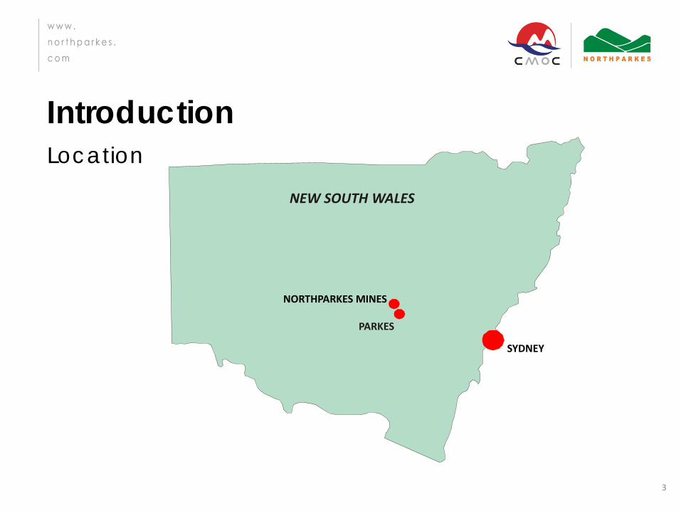
Introduction Location
3
PARKES
SYDNEY
NEW SOUTH WALES
NORTHPARKES MINES

Introduction
4
LIFT 1
E48
LIFT 2
LOADING STATION
CRUSHER
0 200 400
600
800
1000 m
E26
EXTRACTION LEVEL
HOIST
Introduction
5

Introduction
6
Introduction
7
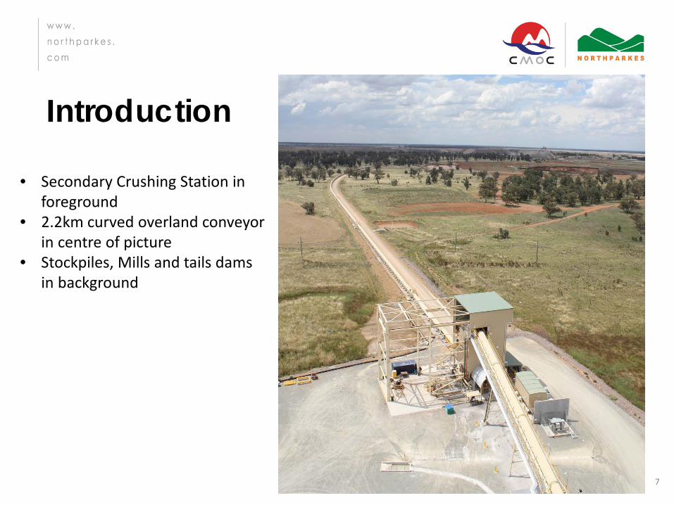
• Secondary Crushing Station in foreground
• 2.2km curved overland conveyor in centre of picture
• Stockpiles, Mills and tails dams in background

Introduction
Dual module processing plant 8

Our Challenge!
9
• 3 Electric Shocks experienced from LHD’s within 6 months (including 2 in 5 days)
• Levels of shock received not clearly understood
• To continue to operate safely without putting our people at risk

10
Incident Shock Description Findings Actions
Cable snapped while operating cable reeler (10/13) (X2)
1. Similar to electric fence
2. Cow kicked me in the chest & back
Snapped at previous join EC tripped Level of shock received not clear.
Understand level of shock received & determine course of action
Shock received while unplugging cable in workshop (4/14)
Pain in arm and tingling sensation on tongue
Isolator was on. Level of shock received not clear.
Understand level of shock received & determine course of action
Our Equipment
11
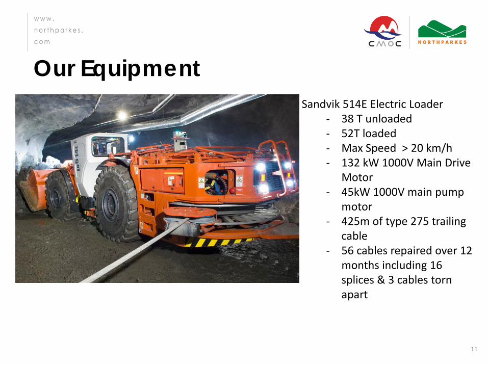
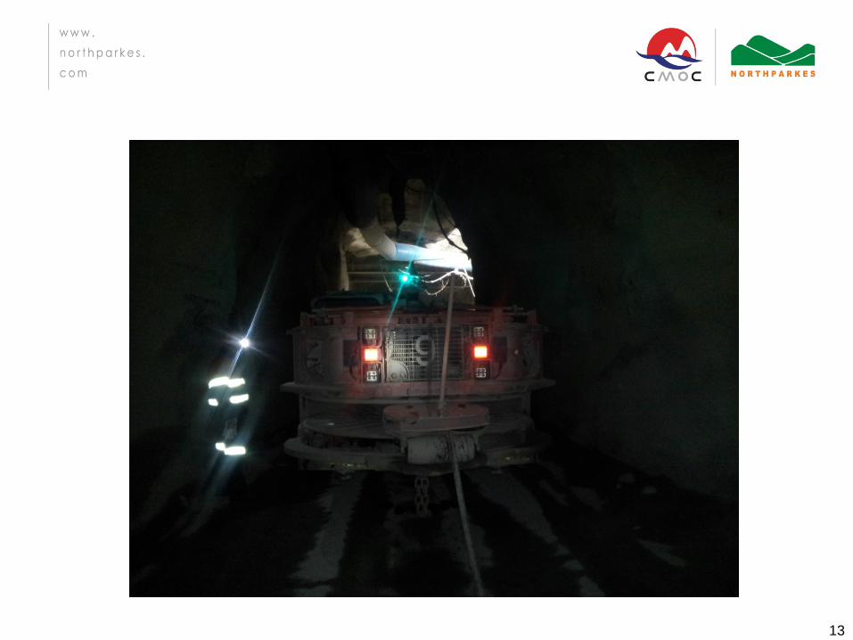
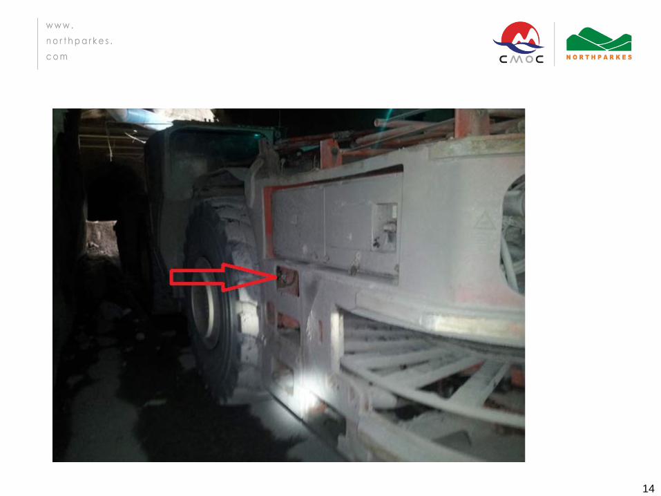
Sandvik 514E Electric Loader - 38 T unloaded - 52T loaded - Max Speed > 20 km/h - 132 kW 1000V Main Drive
Motor - 45kW 1000V main pump
motor - 425m of type 275 trailing
cable - 56 cables repaired over 12
months including 16 splices & 3 cables torn apart
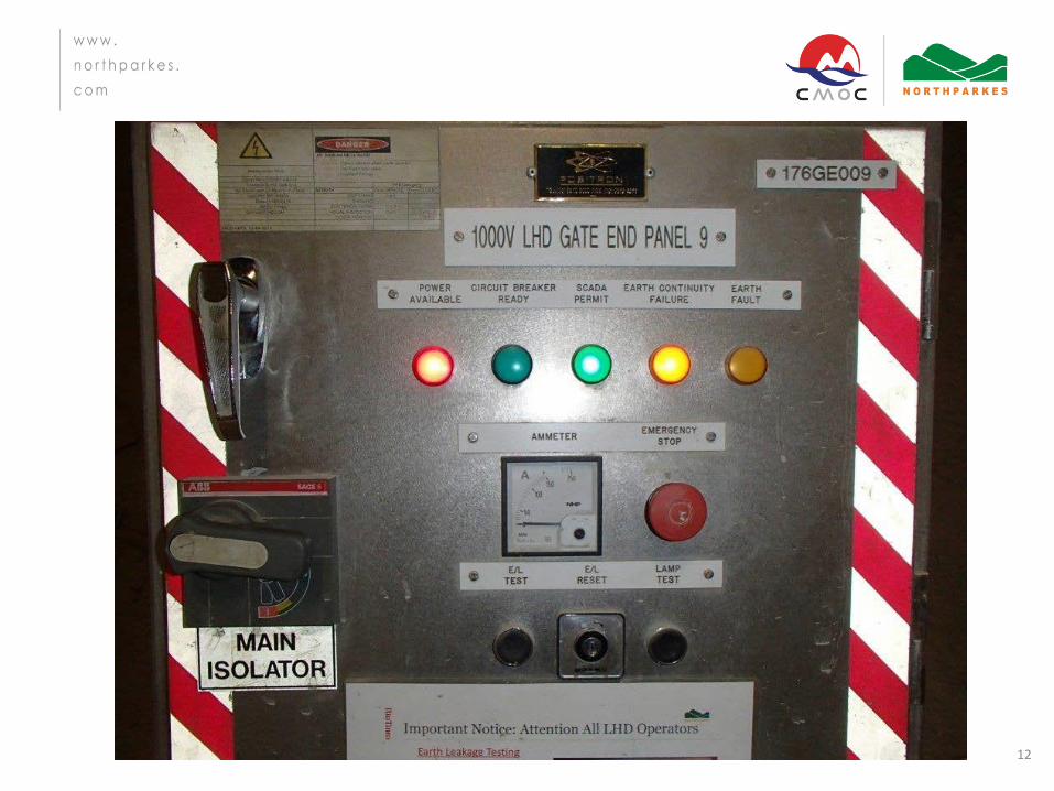
12
13
14

15

16

17
18
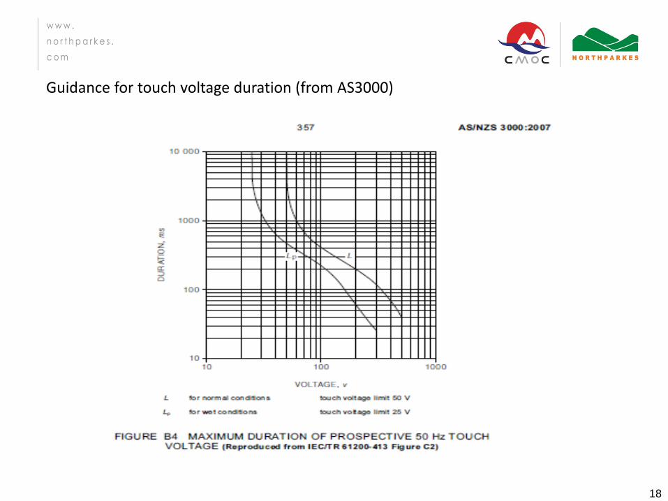
Guidance for touch voltage duration (from AS3000)
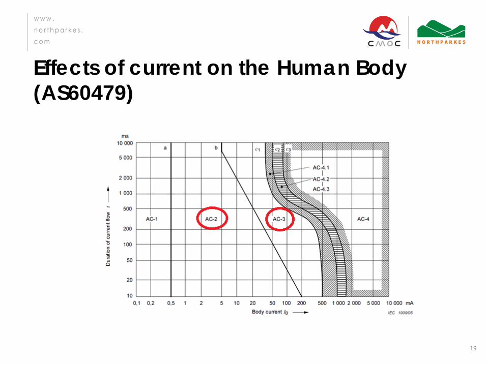
Effects of current on the Human Body (AS60479)
19
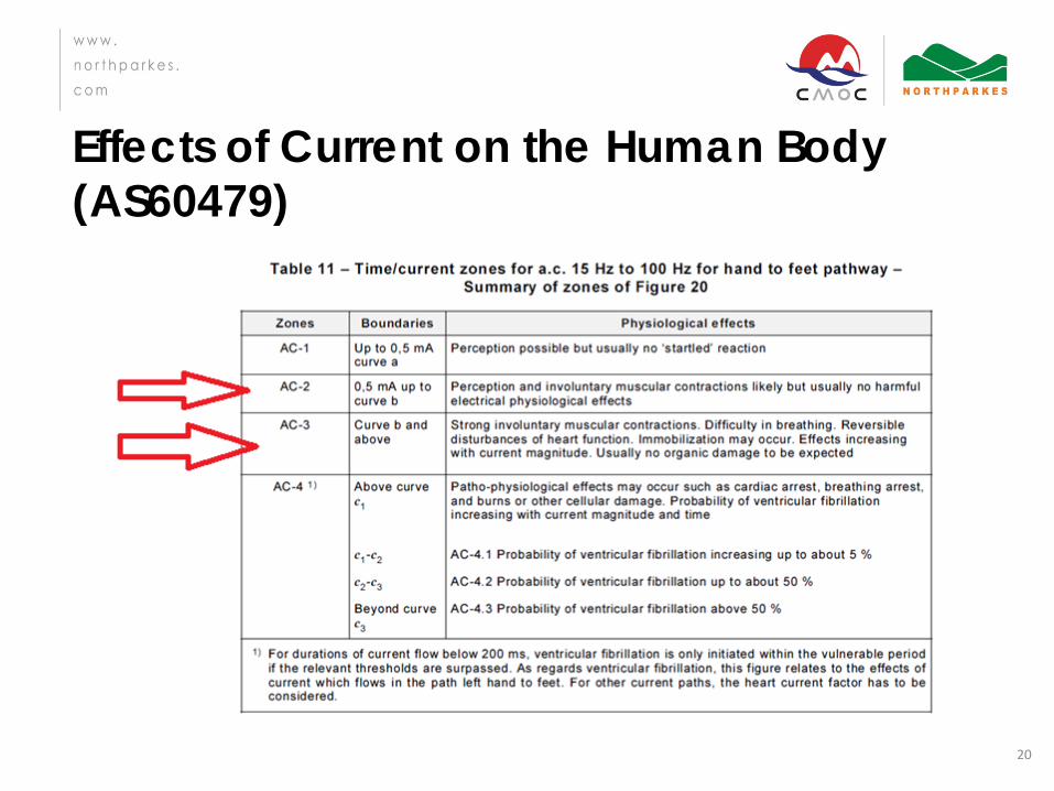
Effects of Current on the Human Body (AS60479)
20
Modelling Process
21
• External consultant (Restech) engaged to model last 3 incidents to determine root cause of shock and likely level of shock received
• Initial engagement actually made at this seminar last year
• Panel inspected & sent offsite for testing • Traditional pilot EC protection not used in this
application
EC System
22
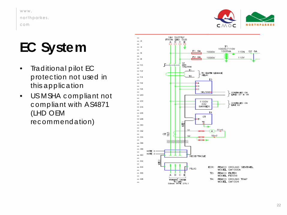
• Traditional pilot EC protection not used in this application
• US MSHA compliant not compliant with AS4871 (LHD OEM recommendation)
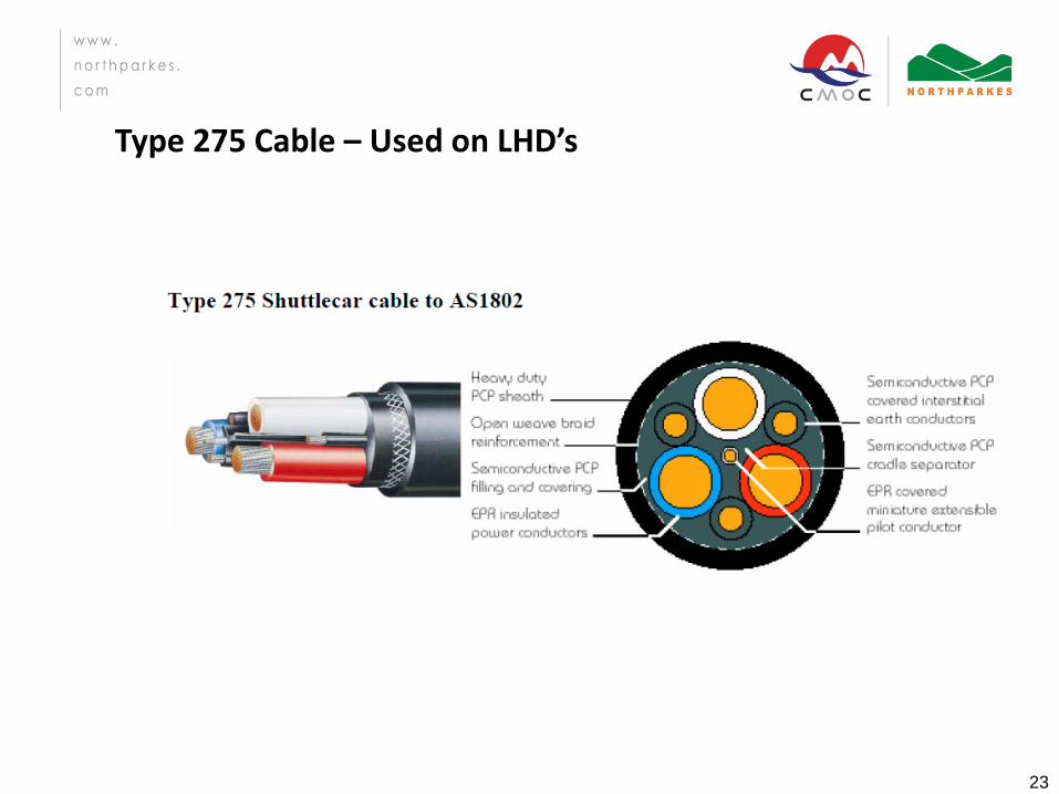
23
Type 275 Cable – Used on LHD’s

Outcomes from modelling & testing (cable breakages)
24
• 7 Cable breakage scenarios modelled – Saturation of Arc Trap in EC circuit contributes to
increased touch potentials under certain failure conditions as does parallel interaction of arc traps
– Most likely breakage scenario of the earths breaking followed by all 3 phases breaking would result in a painful electric shock but would be unlikely to cause ventricular fibrillation. (180 V rms, short duration transient voltage)
– Likely that the voltage would be removed from the cable breaking before the protection operated
– AS4871 requirements met except for EC – C/B on GEB Panel 9 found to be faulty under S/C
conditions

Preventative Actions (cable breakages)
25
• Cut off for cable condition raised from 2 to 5 (AS1747) • Cable management plan implemented • Tested for voltage rise on earth on machine start-up • CB’s replaced (cheaper than testing SC trip function) • New GEB panels manufactured compliant with AS4871 &
AS2081 (using pilot EC protection). Installation Q4 2014 • Interim control to use voltage rated gloves where cables are
under tension • Cable repairs inspected & found to be of a high standard to
AS1747 • EC tested & some adjusted • 10A NER replaced with 5A

26
27
Outcomes from modelling & testing (cable unplugging)
28
– Cable was energised when plug was removed – As plug removed phases make & break creating a phase
imbalance and a transient earth current on reconnection
– Modelling showed the effect of this imbalance and transient earth current was further impacted by the behaviour of the EC circuit contributing to a greater shock potential

Preventative Actions (cable plugging)
29
• Clearly label isolation points including On / Off • Visual indication of a live receptacle • Use of pilot earth system

Key Take Away’s • Don’t assume everything has been commissioned
correctly • Ensure installations and equipment comply with the
relevant Australian Standards. • Continue investigations until the root cause is well
understood and engage external expertise (OEM’s, Consultants) to help understand the issue.
• Foster a work culture where reporting of faults is encouraged and supported.
• Ensure the cookie cutter approach to engineering design & projects is coupled with a design & standards review for new installations.
30