mic1-440 - cctv · pdf filemic1-440 explosion proof cctv ... introduction 3 safety...
TRANSCRIPT

MIC1-440 Explosion Proof CCTV Camera System
Instruction Manual
All Rights Reserved. No part of this document may be reproduced or stored in a retrieval system, or transmitted in any form or by any means, electronic, mechanical, photocopying, recording or otherwise without the prior written permission of Forward Vision CCTV Ltd.
Neither Forward Vision CCTV Ltd nor its affiliates shall be liable to the purchaser of this product or third parties for damages, losses, cost, or expenses incurred by the purchaser or
third parties as a result of: accident, misuse, or abuse of this product or unauthorised modifications, repairs or alterations to this product, or failure to strictly comply with Forward
Vision CCTV Ltd operating and maintenance instructions.
Unit 1, Taplins Court Church Lane, Hartley Wintney
Hants, RG27 8XU Tel:+44-(0)-870 011 3131 Fax:+44-(0)-870 011 3132
www.fvcctv.co.uk
MIC1-440 Instruction Manual Page 1 of 43 Issue 2
CONTENTS
Introduction 3 Safety Instructions 3 Installation 5 Unpacking the camera 6 Installation in workshop 6 Electrical connections 7 Installation on site 7 Earthing the camera. 8 Lightning protection. 8 Connecting with FV CCTV camera terminal box 8 Connection between the camera and the terminal box. 9 Telemetry Connections 10 Power connections outputs 10 Mains connection input 10 Video connection 10 Terminal box indicators. 10 Commissioning the camera using camset 11 Camera preset commands 20 Maintenance 21 Technical Specifications 21 Appendix A. Connecting Mic1- 440 for testing purposes 22 Appendix B. Types of telemetry connection 24 Appendix C Special preset codes 26 Appendix D List of approved repair centres 37 Appendix E Installation Diagrams 38 Drawings 41
Revision record
Issue Date Clause No.
Revision Details Author
1 15/11/2005 First Issue PJE 2 18/01/2007 App. E Armoured Cable Drawing added.
Gland Type No Completed PJE
MIC1-440 Instruction Manual Page 2 of 43 Issue 2

INTRODUCTION The MIC-440 is a complete camera head system specifically designed for use in hazardous areas and is rated up to IIC T6 classification. The robust construction in aluminium or stainless steel makes it ideally suitable for the petrochemicals industry and other demanding environments. The unit is designed to be plug and play making it easy to install, giving considerable reductions in installation and maintenance costs. Safety Instructions This product is designed for use with flammable gases and vapors covered by apparatus groups IIA, IIB and IIC and with temperature classes T1 to T6. The product is certified for use within the ambient temperature range of -20C to +60º C and must not be used outside this range. This product must only be installed by suitably trained personnel in accordance with the relevant code of practice (e.g. EN60097-14:1997). These instructions are intended for their sole use. All installation work should be carried out in accordance with the relevant local and national standards. There are no user serviceable parts and on line maintenance is not required for this product. Inspection and maintenance of this equipment must be carried out by suitably trained personnel in accordance with the applicable code of practice e.g. EN 60079-17. Repair of this equipment must be carried out by suitably trained personnel in accordance with the applicable code of practice e.g. EN 60079-19. NO REPAIRS REQUIRING OPENING THE PRODUCT CASING WHILST IN A HAZARDOUS AREA ARE ALLOWED. Failure to observe this will void the certification and the warranty. Only approved components must be incorporated into or used as replacement parts of this equipment and shall be fitted by suitably trained personnel in accordance EN60079-19. See appendix D for list of approved repair centres. To bring the unit into service, use only assembling, and adjustment equipment as described in the text and diagrams contained in this instruction manual. The certification of this equipment depends upon the maintenance of the flamepaths (see note and table) and the use of the following materials in the construction.
MIC1-440 Instruction Manual Page 3 of 43 Issue 2
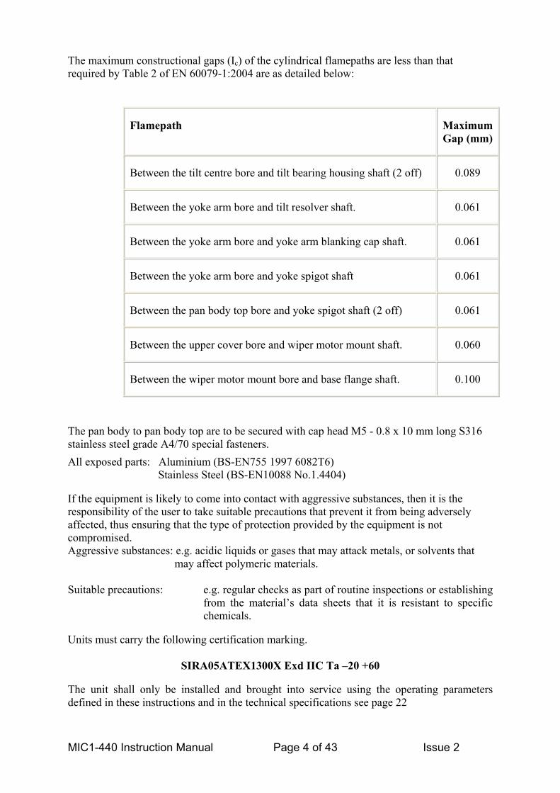
The maximum constructional gaps (Ic) of the cylindrical flamepaths are less than that required by Table 2 of EN 60079-1:2004 are as detailed below:
Flamepath Maximum Gap (mm)
Between the tilt centre bore and tilt bearing housing shaft (2 off) 0.089
Between the yoke arm bore and tilt resolver shaft. 0.061
Between the yoke arm bore and yoke arm blanking cap shaft. 0.061
Between the yoke arm bore and yoke spigot shaft 0.061
Between the pan body top bore and yoke spigot shaft (2 off) 0.061
Between the upper cover bore and wiper motor mount shaft. 0.060
Between the wiper motor mount bore and base flange shaft. 0.100
The pan body to pan body top are to be secured with cap head M5 - 0.8 x 10 mm long S316 stainless steel grade A4/70 special fasteners. All exposed parts: Aluminium (BS-EN755 1997 6082T6) Stainless Steel (BS-EN10088 No.1.4404)
If the equipment is likely to come into contact with aggressive substances, then it is the responsibility of the user to take suitable precautions that prevent it from being adversely affected, thus ensuring that the type of protection provided by the equipment is not compromised. Aggressive substances: e.g. acidic liquids or gases that may attack metals, or solvents that
may affect polymeric materials.
Suitable precautions: e.g. regular checks as part of routine inspections or establishing from the material’s data sheets that it is resistant to specific chemicals.
Units must carry the following certification marking.
SIRA05ATEX1300X Exd IIC Ta –20 +60 The unit shall only be installed and brought into service using the operating parameters defined in these instructions and in the technical specifications see page 22
MIC1-440 Instruction Manual Page 4 of 43 Issue 2

This equipment must be accompanied by a translation of the instructions in the language or languages of the country in which the equipment is to be used and by the instructions in the original language before being put into service. It is important that only cables of suitable types are used and that all fuses or overload protection devices are of suitable rating. It is important to take adequate safety precautions when installing or working on the unit to ensure accident or injuries do not occur due to falling machinery or tools. In situations where there could be a risk of injury, should any part of the assembly become detached for any reason and fall, normal common sense safety precautions should be employed. A strong safety chain between the camera pan shaft and the mounting surface is recommended. Before mounting the unit ensure that the mounting area is capable of supporting the unit under all weather conditions. Ensure that the mounting point and fixings positions are suitable to ensure the unit can be securely mounted. Ensure that all fastenings are secure before leaving installation. Use only the power sources indicated in this user guide. Ensure that the product case is properly earthed and that earth-bonding connections are made correctly to the mounting base of the unit.
To minimise the risk of an electrical hazard ensure that all electrical power is disconnected before working on the unit. It is important to make sure that all electrical power is disconnected at the source end. Do not back drive the pan or tilt axis of the MIC-440 as this will damage the motor drive gear chain and will invalidate the warranty.
Installation The product contains no user serviceable parts and the should not be opened on site as this will invalidate the certification The installation method will depend on the site conditions and installation preferences but the MIC-440 can work up to 25 meters from its power supply. This means that if the power supply can be placed within a non-hazardous area within 25 meters of the MIC unit a standard power supply can be used (see Fig 1).
FIG 1
MIC1-440 Instruction Manual Page 5 of 43 Issue 2

If it is not possible to fit the power supply in a non-hazardous area within 25 meters of the MIC unit the Power supply will be fitted in a suitably rated EExd junction box (see fig 2).
The MIC-440 connecting cab See Appendixuse.
Unpacking
Take carworking surface ( Check that theMIC-440 12 Way cable EExd Barrier GC.D. Containin
InstallationThe unit is supmatch the comExamples of gFor FV StandaFor FV ArmouThe cable is reThis compositAWG) and one
MIC1-440 Ins
Hawke 501/453 UNIV Size 0 for armoured Cable Hawke 501/421 Size 0 for Non- armoured Cable
is designed as a plug and play unit and it is highly recommended that the le be fitted to the unit before installing the unit on site.
E for more detailed installation diagrams defining cables and glands to
the camera.
e when removing the unit from the packaging to ensure that the unit does not roll off the on to your feet!).
packaging included the following parts:
connector. land of correct size and rating to match cable selected.. g installation instruction manual and CAMSET software
in workshop plied with its internal connector and a suitable sized EExd barrier gland to posite cable dia. lands : rd 8mm Dia Cable a Hawke 501/421 Size 0 provided. red Cable 16mm Dia a Hawke 501/453 UNIV Size 0. quired to connect the MIC-440 to its power source, control data and video. e cable consists of two pairs (24AWG) plus 4 cores (22 AWG), 2 Cores (24 coax cable for the video signal.
truction Manual Page 6 of 43 Issue 2

It is recommended that the cable and connector should be made up, connected to the unit and sealed with the EExd barrier gland in a workshop before taking for mounting on site. All connections to the unit are made via the single 12 way connector mounted in the base connector box. Remove the 4 x M8 Hexagon bolts holding the base connector box to the MIC unit and remove the base connector box. . Fit the cable through the EExd barrier gland Fit the cable through the threaded gland hole in the base connection box and allow approx 100mm of free cable on the inside to connect to the 12 way cable connector. Screw the EExd barrier gland into the base connector box and maintain approx 100mm of cable on the inside of the box to enable the cable connector to be freely inserted into the MIC unit base connector. Fit the 12 way connector and make the connections as designated in the table below. Connect the 12 way cable connector into the matching connector in the base of the MIC unit. Make sure the connector is fitted home properly in the camera integral plug (requires approx. two and a half turns of the socket threaded ring to fasten the two halves of the connectors together properly). Fit the base connector box back to the MIC unit and fasten using the 4 x M8 hexagon bolts Ensure that there are no trapped cables. Ensure there is some slack cable in the connector box then tighten up and seal the EExd barrier gland as per the instructions included with the gland.. The unit with the cable tail is now ready for on site installation
Electrical connections The connector pin allocations are as follows: Connector Pin
Signal Name Description. Cable Wire Type
A Video Output. Video Signal output to control room Coax core B Video Return. Video Signal Ref output to control room Coax screen C Tamper Switch. Connection C to D will provide an alarm to the control 24 AWG core D Tamper Switch return. room via telemetry. 24 AWG core E Washer drive return. TTL ref output can be used to drive external relay for
wash operation option. 22 AWG core
F Washer drive. TTL output can be used to drive external relay for wash operation option.
22 AWG core
G Full Duplex Tx A. Telemetry Output RS 485. Pair 1 H Full Duplex Tx B. Telemetry Output.RS485. Pair 1 J Full Duplex Rx A.
Half Duplex Tx/Rx A. Telemetry I/O to RS485. Pair 2
K Full Duplex Rx B. Half Duplex Tx/Rx B.
Telemetry I/O to RS485. Pair 2
L Power input 1. Low volt AC or DC power input 15 Volts AC or DC. 22 AWG core M Power input 2. Low volt AC or DC power input 15 Volts AC or DC. 22 AWG core Video output signal conforms to CCIR PAL 1V Composite format. (NTSC format is available on request). Telemetry signals all conform to the RS485 / RS422 standard. The unit continuously monitors incoming telemetry whether in full or half duplex mode.
MIC1-440 Instruction Manual Page 7 of 43 Issue 2

In full duplex mode, the Tx pins are tri-state except during transmission times. This may cause problems when interfacing to some Fibre Optical converter units. Check out the Commissioning notes for ways of overcoming these problems. Appendix B. In 2 wire Half Duplex mode (RS485), the Rx Pins are used to transmit data to the MIC unit. The washer connections can be used to operate a relay in the power supply unit, which in turn can activate a pump.
INSTALLATION ON SITE
Mounting the unit The MIC-440 can be mounted either way up i.e. with the camera ball up or down. During commissioning the unit can be driven in tilt to ensure the picture is the correct way up. Note: There are no internal adjustments required to set the picture the correct way up.
The unit is supplied with an industrial standard 4” (101.6mm) PCB mounting base and can be mounted on standard CCTV mounting brackets or on tailor made mounting brackets. Forward Vision CCTV. Can supply suitable brackets if required. M8 Stainless steel nuts, bolts and washers should be used to secure the base of the MIC unit to the selected mounting bracket. Ensure the bolts are tight Earthing the camera. The camera and camera housing are electrically isolated so it is important to make sure that a good safety earth is connected. This safety earth should be a bonding connection to the camera’s outside case. Lightning protection. The MIC-440 unit construction is capable of coping with secondary lightning strikes but in installations likely to be exposed to electrical storms it is recommended that external lightning protection units should be fitted. A good earth bonding connection to the case itself will provide protection against damage from secondary strikes. Where there is a risk of a primary strike hitting the camera housing directly it is recommended that a separate lightning conductor be fitted within 0.5 Meters of the camera and at least 1.5 Meters higher than the camera.
CONNECTING WITH FV CCTV CAMERA TERMINAL BOX. For Non-hazardous areas the following terminal boxes can be used. Product No 703/240D for 240v AC input. 703/115D for 115v AC input. 702/24D for 24v AC input. 702/12D for 12v or 24v DC input for battery operation. This terminal box (shown in figure 5). Provides all the support functions for connecting the camera to third party equipment. It comprises of:
MIC1-440 Instruction Manual Page 8 of 43 Issue 2

A weather resistant (IP55) plastic box fitted with four cable glands. A power supply for the MIC1- 440 camera. A second isolated power supply for driving various option cards. E.g. Washer drive card, 8-channel alarm input card (which includes the washer drive circuit). Screw termination of all cables into and out of the box. Correct video termination for the camera coaxial cable. Earth isolation and termination within the unit to correctly control Video earthing and thus prevent Earth loop. For installation in hazardous areas the following terminal boxes can be used. Product No Exd 703/240D for 240v AC input. Exd 703/115D for 115v AC input. Exd 702/24D for 24v AC input. Exd 702/12D for 12v or 24v DC input for battery operation. An Exd IIC or Exd IIB T6 ATEX approved junction box fitted with four cable glands containing: One of the above power supply units for the MIC1- 440 camera. A second isolated power supply for driving various option cards. E.g. Washer drive card, 8-channel alarm input card (which includes the washer drive circuit). Screw termination of all cables into and out of the box. Correct video termination for the camera coaxial cable. Earth isolation and termination within the unit to correctly control Video earthing and thus prevent Earth loop. The terminal box schematic is shown in figure 6. Connection between the camera and the terminal box. Via the composite cable is as per the table below:
MIC1- 440 base connector pin
Numbers.
MIC1- 440 Composite cable
Wire colour
Function Terminal Box Connector
Terminal box ID marking.
L Red AC supply HD3-1 15v AC M Green AC supply return HD3-2 15v AC K White Rx B HD3-3 RXB J Yellow Rx A HD3-4 RXA B Drain Wire Gnd HD3-5 GND G Blue Tx A HD3-6 TXA H Violet Tx B HD3-7 TXB A Coax Core Video HD3-8 VIDEO B Coax Screen Video Return HD3-9 GND C Black Tamper Switch HD3-10 Tamp Sw F Orange Wash HD3-11 Wash
D Brown 0v rtn Tamp Sw HD6-1 0v E Grey 0v rtn Wash HD6-2 0v
MIC1-440 Instruction Manual Page 9 of 43 Issue 2

Telemetry Connections The terminal box can be used as a distribution point for telemetry connections and HD5 and HD4 are connected directly to HD3 on the PCB. This allows connections from the camera cable to be fed back to the control room through a number of different types of connection. HD5 allows connection of the site telemetry cable to be terminated via screw terminal connections. HD4 allows the site cable to be terminated in crimp joints and then be connected to the crimp header connector. HD4 is particularly useful for use during commissioning the camera as it allows rapid connection and disconnection of a test cable connected to a PC running the camera set up and commissioning programme CamSet HD3 is the connector for the camera composite cable.
Telemetry Signal Name HD3 HD4 HD5 RXB Pin 3 Pin 1 Pin 1 RXA Pin 4 Pin 2 Pin 2 GND Pin 5 Pin 3 Pin 3 TXA Pin 6 Pin 4 Pin 4 TXB Pin 7 Pin 5 Pin 5
Power connections outputs 15vAC power is available from the camera terminal box via HD3 pins 1 and 2 identified as 15V AC. This is specifically to drive a single MIC1- 440 camera unit. 12v DC power is generated by a second Power supply on the PCB which is fed to CN2 to drive the ancillary cards that can be fitted to the power supply, e.g. washer drive card and 8 channel alarm card. Max current is limited to approx. 600mA.
Mains connection input. Mains to the terminal box should be connected to HD1 as follows:
Live HD1-1 Neutral HD1-2 Earth HD1-3
If there are no other connections of the camera 0v to earth, via a locally connected fibre interface unit or via a video Opto transmission system or some other third party equipment, then the EARTH LINK situated between HD1 and FS3 should be left intact. If there are other paths between 0v and mains earth then the earth link on the power supply should be cut.
Video connection. Video from the camera coax cable should be terminated on HD3 at pin 8 for Video and pin 9 for Video screen. The tin copper wire VIDEO LINK is fitted during manufacture and should always be in place.
Terminal box indicators. LED1 and LED2 when lit show that 15v AC is available from the power supply. There is no indication of the operation of the Telemetry lines, as this would increase the load on these lines reducing the number of cameras that can be driven by a single telemetry drive.
MIC1-440 Instruction Manual Page 10 of 43 Issue 2
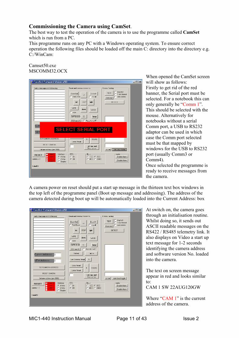
Commissioning the Camera using CamSet. The best way to test the operation of the camera is to use the programme called CamSet which is run from a PC. This programme runs on any PC with a Windows operating system. To ensure correct operation the following files should be loaded off the main C: directory into the directory e.g. C:/WinCam: Camset50.exe MSCOMM32.OCX
When opened the CamSet screen will show as follows: Firstly to get rid of the red banner, the Serial port must be selected. For a notebook this can only generally be “Comm 1”. This should be selected with the mouse. Alternatively for notebooks without a serial Comm port, a USB to RS232 adaptor can be used in which case the Comm port selected must be that mapped by windows for the USB to RS232 port (usually Comm3 or Comm4). Once selected the programme is ready to receive messages from the camera.
A camera power on reset should put a start up message in the thirteen text box windows in the top left of the programme panel (Boot up message and addressing). The address of the camera detected during boot up will be automatically loaded into the Current Address: box
At switch on, the camera goes through an initialisation routine. Whilst doing so, it sends out ASCII readable messages on the RS422 / RS485 telemetry link. It also displays on Video a start up text message for 1-2 seconds identifying the camera address and software version No. loaded into the camera. The text on screen message appear in red and looks similar to: CAM 1 SW 22AUG120GW Where “CAM 1” is the current address of the camera.
MIC1-440 Instruction Manual Page 11 of 43 Issue 2

The message sent out via telemetry looks as follows and will appear in the thirteen text windows in the top left of the CamSet programme screen (called Boot up message and Addressing): ID is:1 Serial No 1160 MIC 440 Model 5A Date 15/02/3 Software Version: 22AUG120GW Multi alarms Sector captions Privacy Camera Initialised Camera OK Where = any character (these are binary characters and will not be understood by the ASCII reader). ID = Camera address. Serial No = control card serial No. Model = build standard of control card. Date = programming date of control card. Receiving the above message shows that out bound telemetry from the camera has correctly reached the telemetry point being monitored and also allows the camera address to be checked. CamSet will automatically set the camera address in the “Current Address” box. Once an address appears in this box then camera commands may be sent out via CamSet to that camera. All “Preset and camera commands” function boxes on the CamSet programme should be self-explanatory. To make the camera move the “SPEED” box is preset to a value of 50 (Max speed = 255 min speed =1). Using the “long test” tick box will send 10,000 test messages, this will take several minutes to complete. Use the “1 sec timeout” box when telemetry is switched through a multi-channel hub and channel switching times are required to allow the hub to correctly switch to the correct channel. If there is doubt about communications with the Sony FCB 480 camera inside the MIC1- 440 then ticking the “cam comms” box will send through test messages to the FCB camera module itself inside the MIC1- 440. Use the “DETECT” button to map all cameras currently connected to the CamSet programme. This process will also list the software version at each camera address loaded into the camera. If non-ASCII characters are seen for the software version No, this indicates that there is a duplication of the camera address on the network with the address that produces the corrupted response.
MIC1-440 Instruction Manual Page 12 of 43 Issue 2

To Change the address of a camera on the network, firstly ensure that either the address being changed from is unique or ensure that the camera whose address is being changed is the only one connected to the CamSet programme. Set in the “NEW Address” window the address to which the camera is to be changed. Then select the “Set Camera Address” button. To check that the camera address has indeed changed, either power down and re-power the camera or change the “Current Address” window to the address just selected and select the “RESET CAMERA” button. Either action should result in a new start up message and a new 1-2 sec ID message on the Video picture reflecting the new address just set into the camera. (For cameras built before the year 2000 the set new address pre2000 button must be used to change camera address). Pot Test button.(FV protocol only) This allows the operation of the camera to be tested in real time. This function only works if the camera is used in Duplex mode. Selecting Pot test will generate a graph as shown below:
The red trace represents the Pan position and is driven by the readout for PAN 3304 under the Pan Left button. The green trace represents the power drawn by the Pan axis servo to make the motor move at the required speed. The actual power being shown by the Pan PWM 53. The blue trace represents the Tilt position and is driven by the readout for TILT 2789 under the
Tilt Up button. The Violet trace represents the power drawn by the Tilt axis servo to make the motor move at the required speed. The actual power being shown by the Tilt PWM 32. The Pot Checker is useful for looking at the servo performance of the camera both for manual move commands and for presets (1 and 2 only are made available on this screen).
Exec Camera Preset allows any one of the preloaded camera module preset to be executed. These presets are mapped to presets 240 to 249 as per page 19 where the use of the SonySet
programme is explained.
Goto and Learn presets are allowed for only on presets 1 to 10 for this test software. Clicking the numeric button to the right of the goto and learn buttons will sequentially select the next preset mode. The blank window under the Learn Preset button allows any
Learn Preset or Goto Preset command to be executed. Simply load the preset number required in the blank window then select the appropriate preset button. This mechanism allows any of the special function presets to be executed. See Appendix C for a complete list of special preset codes.
MIC1-440 Instruction Manual Page 13 of 43 Issue 2

Pressing the TOURS button produces the sub screen to the left. This allows simple tours to be set up from CamSet. Dwell time is in seconds. Don’t forget to store the tour to transfer the details of the tour to the camera Flash memory. Auto tour on/off allows the tour to start if no manual move commands for this camera are received over a 5 minute period. Pressing the SoftStops and Dwell zones button produces the red sub-screen, on the left: Softstop defines a rectangular area beyond which the camera cannot go in either pan or tilt. Dwell Zone defines a rectangular area in which the camera cannot come to rest but continues to move in the direction last selected until the boundary is reached. If for any reason a soft stop or non dwell zone gets partly set the result will be that the camera can only move in one direction. For example left, but not right. Or up, but not down. If this happens clearing the softstops and dwell zone will resolve this problem.
Using the Setups Button. When the Setups button is selected the sub window shown on the left is opened. This provides access to a number of features that can be switched on or off by telemetry. WashWipe On/Off. If selected to On, a wash preset position can be learned by pointing the camera at the washer nozzle and setting Wash position. When the Wash button is pressed the camera remembers its current position, moves to the washer nozzle position and starts the washer and wiper. Whilst the washer button remains depressed, the washer and wiper continue to run. On release of the wash button the washer stops and the camera returns to its previous view. After a further two wipes the wiper stops too.
Auto Alarm On/Off. Operates as per the Wash Wipe On/Off. On all Mic1- 4000s a single tamper switch input is supported. With Auto Alarm selected on and an alarm position learned, the camera will move to the alarm position when the tamper switch is operated. If the Auto Alarm is selected to off, the camera still reports the status of the alarm bit to the control system but the camera does nothing else in response to the tamper switch input. Multi Alarm On/Off. The Multi Alarm facility is used in conjunction with the Multi Alarm Setup window and can only be used if the 8 or 10 channel alarm scan card is fitted to the power supply box. Normally Set to Multi Alarm off to prevent inconsistent operation of the camera.
MIC1-440 Instruction Manual Page 14 of 43 Issue 2

The numeric buttons 1 to 12 allow for the learning of alarm presets positions for each of the alarm channels, normally 1 to 8 but 9 to 12 have been included for future designs. To make the camera go to these presets when the alarm is activated, both the Auto Alarm On and Multi Alarm On must be selected. The alarm scan card fitted in the power supply has on it two relays for alarm status output and additionally a relay to drive a washer pump. The relay operation is controlled as follows:
Any alarm activates
relay √ Only alarms shown activate
relay Relay closes on alarm √ Relay opens on alarm
The relay alarm re-arm time is controlled by the four radio buttons. Times shown are in seconds.
Once the relay operation has been defined, as above the Set relays box must be selected to load the relay status into the MIC1- 440 camera. Other functions:
Digital Zoom On/Off sets the availability of Digital zoom permanently. This function can only be changed from this point. Auto Flip On/Off allows the camera to pan 180 degrees when mounted ball down and the target being tracked passes directly under the camera. Note: It does take 2 seconds for the camera to slew 180 degrees
so be aware of this time delay during the operation of this function. Auto Home. This function allows the camera either to go to preset 1 or to restart a tour (sequence) if the camera receives no commands to move from the operator for a period of 5 mins. Min Int Spd. This parameter limits the camera to a minimum frame integration (shutter speed) rate
Min Int Spd value
actual minimum frame rate.
06 50 05 25 04 12 03 6 02 3 01 2 00 1
regardless of lighting conditions. This prevents the camera going down to a frame rate that is too low for the application the camera is being used in. Values set in the box represent the following settings:
MIC1-440 Instruction Manual Page 15 of 43 Issue 2

Max Gain Lvl. This parameter sets the maximum gain the camera reaches before frame integration (lower shutter) speed starts to apply
Min Gain Lvl value
Actual minimum gain level.
0F 28 db 0E 26 db 0D 24 db 0C 22 db 0B 20 db 0A 18 db 09 16 db 08 14 db
AutoLowlight On/Off. Under low light conditions the camera will automatically go into frame integration mode if this is set to On. Under these conditions the camera will return the best picture it can for the lighting conditions prevailing. But if light levels are very low then the frame rate can be as low as 3 frames a second. This makes movement through the cameras field of view very jerky. Default Presets. The 64 off Pan/Tilt/Zoom presets can be set to default mid range values should the camera be found to be responding erratically to preset positions. This can happen if a preset position has been loaded by the control system that is outside the normal preset working range. The two numeric boxes can be used to set the lower and upper limits of the preset range that is defaulted if not all 64 presets need to be reset. Other sub-screen:
These three buttons open up further sub screens with additional functions.
780 setup.
This sub screen was set up to help with the Sony FCB-EX780 camera module when fitted to the Mic1- 440 camera. As with hand held video cameras this module has a lens stabilisation system Anti shake ON/OFF, which can be activated by telemetry. It is particularly good at knocking out high frequency vibrations. Auto IR ON/OFF and Auto Integration ON/OFF These commands go directly to the 780 module unlike the functions under Setups. Which correctly adjusts the 480 camera module and control card operation. LENS RECALIBRATION. Is not used on this unit.
MIC1-440 Instruction Manual Page 16 of 43 Issue 2

Captions.
The operation of this sub-screen is self explanatory. Only a single line of text can be input and a maximum of 20 characters can be input. The Set/Clear Captions toggles the appearance of captions on the camera video. It is not possible to tell which way the toggle is set except by inspecting for on screen text. Typing in text in the top window followed by selecting the Set Caption button will upload the test to the camera. The 8 off radio buttons select where the caption appears on the Video picture. Bottom Right is not allowed. Set All Preset Captions will set what ever text is set for the base camera and will then add the preset number to each caption so that each preset has a different caption associated with it.
Blank Preset Captions blanks all captions for all 64 preset positions. NOTE: Warning:
The cam baud toggle button causes the camera to change from its default operating baud rate of 9600 to 4800. Having selected this
button, all comms to the camera will be lost until CamSet is reset to 4800 baud. Then communications will be re-established. The cam baud toggle button can then be selected again to return the camera to 9600 baud. CamSet must also be returned to 9600 baud to allow operation to continue. Interface control.
In conjunction with an appropriate RS232 to RS485 / RS422 adaptor these radio buttons control the way CamSet communicates with the camera. The changes are active directly
on selection. See Appendix A, Connecting CamSet to set up different adaptors for operation with the CamSet Programme. Forward Vision CCTV Ltd also provide their own front-end control system for use with this camera. The software runs on an IBM compatible PC and is called WinCam. Further details on this product are available on request.
MIC1-440 Instruction Manual Page 17 of 43 Issue 2
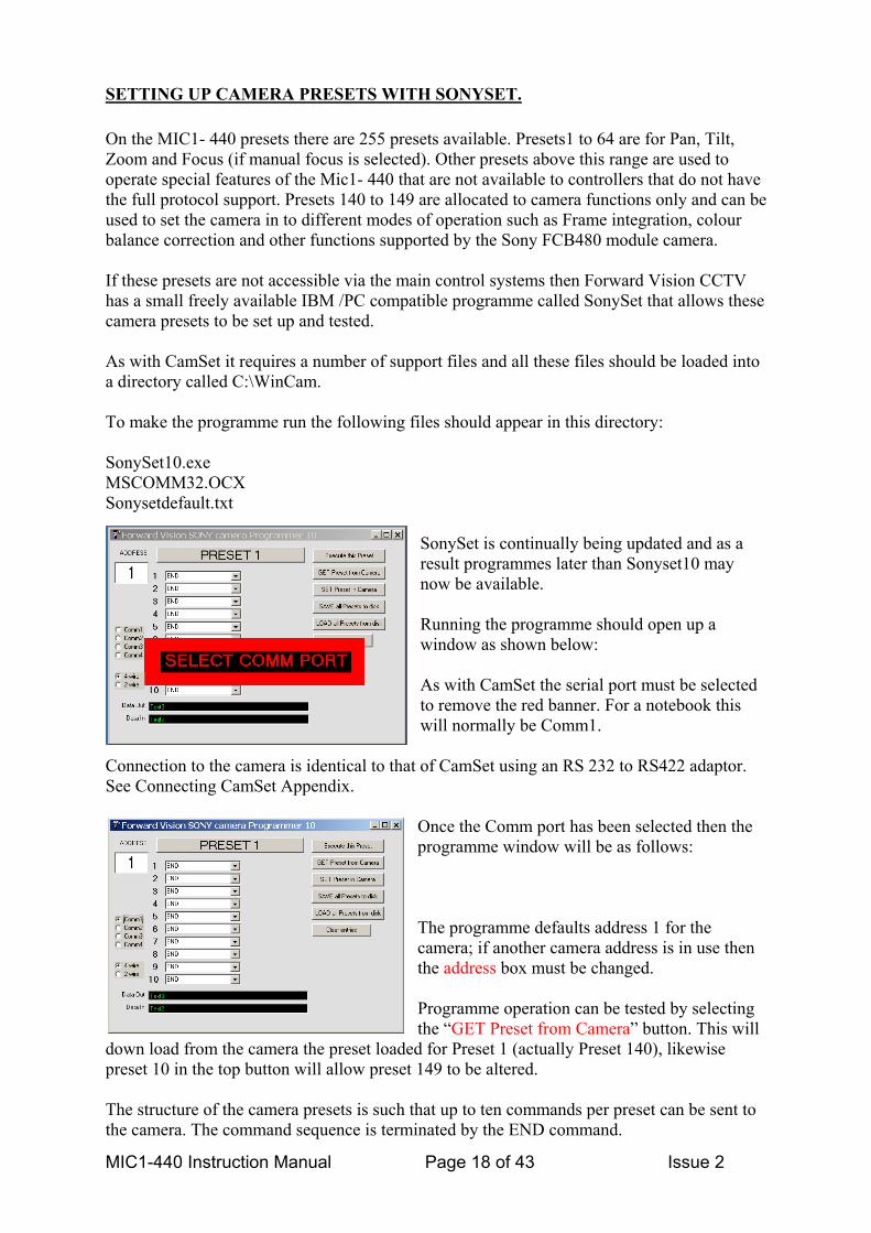
SETTING UP CAMERA PRESETS WITH SONYSET. On the MIC1- 440 presets there are 255 presets available. Presets1 to 64 are for Pan, Tilt, Zoom and Focus (if manual focus is selected). Other presets above this range are used to operate special features of the Mic1- 440 that are not available to controllers that do not have the full protocol support. Presets 140 to 149 are allocated to camera functions only and can be used to set the camera in to different modes of operation such as Frame integration, colour balance correction and other functions supported by the Sony FCB480 module camera. If these presets are not accessible via the main control systems then Forward Vision CCTV has a small freely available IBM /PC compatible programme called SonySet that allows these camera presets to be set up and tested. As with CamSet it requires a number of support files and all these files should be loaded into a directory called C:\WinCam. To make the programme run the following files should appear in this directory: SonySet10.exe MSCOMM32.OCX Sonysetdefault.txt
SonySet is continually being updated and as a result programmes later than Sonyset10 may now be available. Running the programme should open up a window as shown below: As with CamSet the serial port must be selected to remove the red banner. For a notebook this will normally be Comm1.
Connection to the camera is identical to that of CamSet using an RS 232 to RS422 adaptor. See Connecting CamSet Appendix.
Once the Comm port has been selected then the programme window will be as follows: The programme defaults address 1 for the camera; if another camera address is in use then the address box must be changed. Programme operation can be tested by selecting the “GET Preset from Camera” button. This will
down load from the camera the preset loaded for Preset 1 (actually Preset 140), likewise preset 10 in the top button will allow preset 149 to be altered. The structure of the camera presets is such that up to ten commands per preset can be sent to the camera. The command sequence is terminated by the END command.
MIC1-440 Instruction Manual Page 18 of 43 Issue 2

The total number of commands available to the camera is 122. The commands available can be seen by opening up the command window using the arrow key to the right of the window, thus:
Any one of the commands can then be selected into that command window. Each command window can be set up to a different command if required. There is no validity testing of this process so it is possible to set up inappropriate command sequences. Care should be exercised when modifying the command structures. Command structure can then be tested using the ”Execute this preset” button. Modified commands must be stored to the camera
before they take effect using the “Set preset in camera” button. Once a camera has been set up with presets, all presets loaded can be saved to disk for reloading into other cameras if required. If things get out of control then the defaultsetup.txt setting can be reloaded into the MIC1- 440 using the “Load all presets from Disk” button.
At manufacture the camera is preloaded with the defaultsetup.txt Camera presets:
These provide the following camera functions: Preset 1, (240) Back light compensation on. Preset 2, (241) Back light compensation off. Preset 3, (242) White balance Manual, Red gain set: 64, blue gain: set 192. Attempts to correct for sodium lighting. Preset 4, (243) White balance outdoor. Preset 5, (244) exposure: shutter priority, shutter: set 3 Frame integration mode 25 f / s Preset 6, (245) exposure: shutter priority, shutter: set 2 Frame integration mode 12 f / s. Preset 7, (246) exposure: shutter priority, shutter: set 1 Frame integration mode 6 f / s. Preset 8, (247) exposure: shutter priority, shutter: set 0 Frame integration mode 3 f /s. Preset 9, (248) exposure: auto Preset 10, (249) on screen data: off, exposure: auto, White balance: outdoor, Backlight: off General camera reset (puts everything back to normal). This is a list of all the possible commands. You can arrange 10 presets with 10 of the following commands in each. Presets are recalled with standard Goto Preset commands. Camera preset 1 is preset 240; camera preset 2 is preset 241 etc, etc.
MIC1-440 Instruction Manual Page 19 of 43 Issue 2

CAMERA PRESET COMMANDS: cam power: on cam power: off cam zoom digital zoom: on digital zoom: off focus autofocus manual focus focus one push trigger focus force infinity AF sensitivity: high AF sensitivity: low focus near limit set white balance: auto white balance: indoor white balance: outdoor white balance: one push white balance: auto tracing white balance: manual white balance: one push trigger red gain: reset red gain: +1 red gain: -1 red gain: set blue gain: reset blue gain: +1 blue gain: -1 blue gain: set exposure: auto exposure: manual exposure: shutter priority (frame int) exposure: iris priority exposure: gain priority exposure: bright exposure: shutter auto exposure: iris auto exposure: gain auto slow shutter: auto slow shutter: manual shutter: reset shutter: +1 shutter: -1 shutter: set iris: reset iris: +1 iris: -1 iris: set gain: reset gain: +1 gain: -1 gain: set bright: reset bright: +1 bright: -1 bright: set exposure comp: reset exposure comp: +1 exposure comp: -1 exposure comp: set exposure comp: on exposure comp: off
backlight: on backlight: off aperture: reset aperture: +1 aperture: -1 aperture: set low lux: on low lux: off ir leds: on ir leds: off left/right reverse: on left/right reverse: off freeze frame: on freeze frame: off effect: off effect: pastel effect: negative effect: sepia effect: black and white effect: solarize effect: mosaic effect: slim effect: stretch digital effect: off digital effect: still digital effect: flash digital effect: lumi digital effect: trail digital effect: level camera memory: reset camera memory: set camera memory: recall on screen data: on on screen data: off date display: on date display: off time display: on time display: off caption display: on caption display: off
MIC1-440 Instruction Manual Page 20 of 43 Issue 2
Maintenance The unit contains no maintainable parts and in the event of failure should be removed from site for repair. Maintenance and repair of this equipment shall only be carried out by suitably trained personnel in accordance with the applicable code of practice (e.g. EN60097-19) To maintain the validity of the certification only components supplied by FVCCTV Ltd shall be used. On site Inspection It is recommended that the equipment be inspected on site every six months to check mounting bolts for tightness, security and any signs of physical damage. Inspection of this equipment shall only be carried out by suitably trained personnel in accordance with the applicable code of practice (e.g. EN60097-17)
Technical Specifications Physical Characteristics Housing: Ruggedised metal housing with environmental protection to IP68. Certified Explosion Proof rated to EExD IIC T6. & ATEX 94/9/EC Annex III Fitted with 12mm tempered glass window. Weight: < 15 kg. Height: < 55 cm. Width : < 30 cm, Depth: < 20 cm Power Supply Power Requirement: Less than 20W Max, 10W nominal at 18V ac/dc input. Environmental Temperature Range: -20°C to +60°C.
Accessories: Built in wiper mechanism. Built in Telemetry Receiver. Camera: 18X Optical zoom. 48° to 2.7° angle of view. 12X Digital zoom.
Resolution :- 460TVL. Colour/Mono with switchable IR cut Filter. Auto/Manual Focus. Auto/Manual Iris with slow shutter (Integration) modes. Minimum illumination 0.7Lux in colour at 50fps.
Telemetry Receiver: Continuous Rotation
64 Presets, accurate to less than 0.1°. 6 tours each with up to 32 presets. Variable speed from 48° per second to 0.2° in pan. Speed control linked to zoom position. 10 Camera setup presets. Simplex, half and full duplex operation. Up to 10 external alarms and 2 output relays (optional). External washer pump drive (optional). Compatible with many proprietary protocols (see protocol list).
MIC1-440 Instruction Manual Page 21 of 43 Issue 2

APPENDIX A.
CONNECTING CAMSET OR SONYSET TO A MIC1- 440 FOR TESTING PURPOSES. THIS PROCEDURE MUST BE CARRIED OUT IN A NON- HAZARDOUS AREA (Unless the pc and RS232/RS485 adaptor are certified for use in the hazardous area) Connecting the Greenwich RS232 to RS422 adaptor unit. The PC should be connected to an RS232 to RS422 adaptor unit via the PC’s serial port. If it is a notebook this will generally be Comm. port 1. A suitable adaptor unit is the Farnell 778-758. To connect the adaptor to the PC you will also need a 9 pin D female to 25 pin D male RS232 compatible adaptor cable. Suitable cable is Farnell 960-573.. The adaptor should be set to DCE mode and it’s power supply connected up. Connections from the adaptor to the Mic1- 440 power supply are as follows:
Adaptor Connections House wire HD4 F 778-758. Colours. Connection. DATA OUT 6-3+ White RXB DATA OUT 5-4- Yellow RXA Screen 0v DATA IN 4-5- Blue TXA DATA IN 3-6+ Violet TXB
The connections can be tested by selecting the DETECT button in CamSet and checking to see if the window below this button displays the address and software version No of the camera being tested. Should problems be encountered then the MIC1- 440 screen or 0v point should be connected via a separate wire to the PC chassis or case to ensure 0v continuity. Connecting the KK systems K2-ADE RS232 to RS485 / RS422 adaptor unit. This unit is self-powered and so does not need external power to make it operate. This only works providing all connections on the RS232 to PC side are made as follows:
RS232 Pin No. Signal 2 Rx 3 Tx 4 DTR 5 Gnd 7 RTS
Alternatively the adaptor can be plugged directly into the back of the PC. If the RS485 / RS422 twisted pair cable between the adaptor and the MIC1- 440 being controlled is in excess of 200mtrs then +9vDC power can be fed to pin 9 of the RS232 side of the KK adaptor (0v to pin 5). Care should be taken to ensure that +9v does not get to pin 9 of the PC comm port connector.
MIC1-440 Instruction Manual Page 22 of 43 Issue 2

RS 485 2 wire mode. RS485 connections and DIP switch settings for 2-wire mode should be made as follows: Adaptor Connections House wire HD4 DIP
switch Setting
K2-ADE. RS485 Colours. Connection. Sw 1 ON Pin 3 White RXB Sw 2 OFF Pin 8 Yellow RXA Sw 3 OFF Pin 5 Screen 0v Sw 4 ON Not required Blue TXA Sw 5 OFF Not required Violet TXB Sw 6 ON
RS422 4 wire mode. RS422 connections and DIP switch settings for 4-wire mode should be made as follows: Adaptor Connections House wire HD4 DIP
switch Setting
K2-ADE. RS422 Colours. Connection. Sw 1 OFF Pin 3 White RXB Sw 2 OFF Pin 8 Yellow RXA Sw 3 OFF Pin 5 Screen 0v Sw 4 ON Pin 2 Blue TXA Sw 5 OFF Pin 7 Violet TXB Sw 6 ON
With all of the above in place and the CamSet program running on a notebook with a Serial Comm port, set up to:
CamSet Tabs 2 Wire RS485 4 wire RS422 Comm 1 Selected Selected Interface 2 Wire 4 wire RTS Off On Baud 9600 9600
If the Notebook does not have a serial Comm port then the USB port can be used and a USB to RS232 adaptor installed. Usually this will be mapped to Comm 3 or Comm 4 by the USB driver software.
MIC1-440 Instruction Manual Page 23 of 43 Issue 2
APPENDIX B.
Types of telemetry connection. Telemetry can be transported to and from the camera via a number of different media: Direct Copper twisted pair connection. Fibre optic transmission system (private or via third party e.g. British Telecom.) Radio or microwave system.
DESCRIPTION OF THE RS422 / 485 DATA LINK VIA CABLE CONNECTION. The details provided below are for a cable connected system. In such a system cable lengths are restricted to the maximum capable of being driven by the cable drivers. Typically this will be of the order of 1Km, but will depend very much on the cable’s core to core and core to screen capacitance. In general terms the greater the diameter of the cable the smaller the cable capacitance per metre length. The telemetry link used on the camera complies with RS422 and RS485 specifications. Via telemetry the unit can be configured to operate in four wire full duplex, two wire half duplex and two wire simplex mode. In simplex mode there is no return telemetry from the camera and many of the advanced featured available to the camera will not be available. RS422 four wire full duplex operation. In this mode of operation four wires are required between the control room and the camera to carry telemetry. One twisted pair carry telemetry data from the control room to the camera and a separate twisted pair is used to carry return data from the camera to the control room. A typical multi camera system is shown in Fig 1. To ensure the best performance out of the system the twisted pair cable should be terminated at both extreme ends. Typical termination resistances of 120 Ohms should be used. No other resistance or terminations should be placed across the twisted pair along any of its length. The camera to control room twisted pair consists of a multiple of transmitters all feeding a single receiver at the control room. To prevent all the transmitters trying to use the twisted pair at the same time the telemetry protocol ensures that cameras cannot transmit unsolicited data back to the control room. To ensure correct operation of the link in this direction each transmitter is held in a tri-state condition so as not to load up the telemetry line when another transmitter is using it. When the line is not in use i.e. no transmitter switched on then in accordance with the RS422 spec. the link takes up an undefined state. This condition may cause problems to some RS422 receivers in the control room. To prevent this, a line bias can be provided by the control room RS422 receiver. Commonly called the ‘Failsafe’ termination this will provide very low Bit Error Rates and ensure minimum data reflections on the line. Figure 1 illustrates the best failsafe termination at the control room. This type of connection is most suitable for connection to a fibre interface unit for long distance transmission to the control station. Four wire connections are generally preferred by third party microwave and radio interface equipment too. RS485 two wire half duplex operation.
MIC1-440 Instruction Manual Page 24 of 43 Issue 2

This type of connection for an all cable system is shown in figure 2. The twisted pair cable should be terminated at each extreme end with a termination resistance of typically 120 Ohms. All bus conflicts and tri-state conditions on the line are controlled by the camera and third party equipment at the control room. In general this is the preferred link configuration for a cable connection to the control room. Cable routing is not particularly fussy and either a star or a daisy chain connected configuration may be used. The total cable length of the entire network will be restricted by the twisted pair cable capacitance and in general terms will be approx. 1000 mtrs. Star spur lengths wherever practical should be kept to a minimum. For small system networks where there may be less than 64 cameras on the copper network and no more than two or three operators using the cameras at the same time there should be no apparent performance degradation over a four wire full duplex system. RS485 two wire simplex operation. This is the simplest connection that can be made to the camera. In this mode the camera simply accepts and obeys commands received. There is no return telemetry and therefore no confirmation to the control equipment that the telemetry command got through. As a result there cannot be any message retry capability. Some camera functionality will be lost. Such as: Return Software version No. Return Current camera position. Return camera status. Return camera health. Command retry, correction of bad comms. Connection of a typical simplex connected system is shown in figure 3. The twisted pair line should be terminated at each extreme end with a resistance of typically 120 Ohms. No other termination should be fitted at any other point on the cable. Cable routing is not particularly fussy and either a star or a daisy chain connected configuration may be used. The total cable length of the entire network will be restricted by the twisted pair cable capacitance and in general terms will be approx.1000 mtrs. Star spur lengths where ever practical should be kept to a minimum. This type of link might typically be used where the reduction in functionality is not an issue and telemetry is transmitted in simplex form over the copper video cable as an FSK sub-carrier by third party FSK system manufacturers.
MIC1-440 Instruction Manual Page 25 of 43 Issue 2

APPENDIX C
SPECIAL PRESET CODES FOR WINCAM BASE LINE PROTOCOL. PAN_REVERSE_ON_PRESET Learn preset 194 PAN_REVERSE_OFF_PRESET Learn preset 195 AUTO_IR_ON_PRESET Learn preset 196 AUTO_IR_OFF_PRESET Learn preset 197 INTERMITANT_WIPE_ON_PRESET Learn preset 198 INTERMITANT_WIPE_OFF_PRESET Learn preset 199 SOFTLIMIT_TOP_LEFT_PRESET Learn preset 200 SOFTLIMIT_BOTTOM_RIGHT_PRESET Learn preset 201 NONDWELL_TOP_LEFT_PRESET Learn preset 202 NONDWELL_BOTTOM_RIGHT_PRESET Learn preset 203 AUTOHOME_PRESET1_PRESET Learn preset 204 AUTOHOME_SEQUENCE_PRESET Learn preset 205 AUTOHOME_OFF_PRESET Learn preset 206 MULTI_ALARM_ON_PRESET Learn preset 207 MULTI_ALARM_OFF_PRESET Learn preset 208 NOTE: Set this AND AUTO_ALARM on to activate MULTI ALARM 1 goes to preset 53 MULTI ALARM 8 goes to preset 61 DIGITAL_ZOOM_DISABLE Learn preset 209 DIGITAL_ZOOM_ENABLE Learn preset 210 SET_TOUR1_PRESET Learn preset 211 SET_TOUR6_PRESET Learn preset 216 AUTOFLIP_ON_PRESET Learn preset 217 AUTOFLIP_OFF_PRESET Learn preset 218 WASHWIPE_ON_PRESET Learn preset 219 WASHWIPE_OFF_PRESET Learn preset 220 Auto wash-wipe Go to preset 62* AUTO_ALARM_ON_PRESET Learn preset 236 AUTO_ALARM_OFF_PRESET Learn preset 237 Auto alarm goes to preset position 63
MIC1-440 Instruction Manual Page 26 of 43 Issue 2

AUTO_LOWLIGHT_ON_PRESET Learn preset 238 AUTO_LOWLIGHT_OFF_PRESET Learn preset 239 CAMERA_COMMAND_PRESET1 go to preset 240 default: backlight on CAMERA_COMMAND_PRESET2 go to preset 241 default: backlight off CAMERA_COMMAND_PRESET3 go to preset 242 default: manual white balance, blue boost CAMERA_COMMAND_PRESET4 go to preset 243 default: outdoor white balance CAMERA_COMMAND_PRESET5 go to preset 244 default: frame integration 24 fps CAMERA_COMMAND_PRESET6 go to preset 245 default: frame integration 12 fps CAMERA_COMMAND_PRESET7 go to preset 246 default: frame integration 6 fps CAMERA_COMMAND_PRESET8 go to preset 247 default: frame integration 3 fps CAMERA_COMMAND_PRESET9 go to preset 248 default: frame integration off CAMERA_COMMAND_PRESET10 go to preset 249 default: normal settings These can be changed with SonySet CAMERA MODULE RESET Learn PRESET 251* ON SCREEN MENU (Toggle on/off) Learn preset 254
MIC1-440 Instruction Manual Page 27 of 43 Issue 2

SPECIAL PRESET CODES FOR OTHER PROTOCOLS Philips protocol control codes 11/1/02 Address change: Set aux 14 on, 21 on, 21 off, aux N on or off. where N is the new address OR Goto preset 76, goto preset 90, goto preset 91 the learn preset n where n is the new address. Set non-dwell zone: Learn preset 97 for top left, 98 for bottom right Set Softstop: Learn 95 for top left and 96 for bottom right. Aux: 1 manual focus 2 digital zoom 3 manual exposure 4 auto low light 5 wiper 6 washer 7 scaled ptz 8 low lux 9 camera power 10 backlight 11 b&w 12 on screen data 13 frame int 6 fps 14 re program 1 15 pan reverse 16 auto alarm goto preset 49 on alarm open 17 on start sequence 17 off program short fast seq. 1 to 5 every 5 seconds 18 on program short med seq. 1 to 5 every 15 seconds 18 off program short slow seq. 1 to 5 every 60 seconds 19 on program long fast seq. 1 to 10 every 5 seconds 19 off program long med seq. 1 to 10 every 15 seconds 20 on program long slow seq. 1 to 10 every 60 seconds 21 on re-program 2 21 off re program 3 22 on auto home after 5 minutes got preset 48 22 off 23 on Auto white balance 23 off Outdoor white balance Goto Preset: 50 manual focus on 51 off 52 digital zoom on 53 off 54 manual exposure on 55 off 56 auto low light on 57 off 58 wiper on 59 off
MIC1-440 Instruction Manual Page 28 of 43 Issue 2

60 washer on 61 off 62 scaled ptz on 63 off 64 low lux. on 65 off 66 camera power on 67 off 68 backlight on 69 off 70 b&w on 71 off (colour) 72 on screen data on 73 off 74 frame int. 6 fps on 75 off 76 re program 1 77 78 pan reverse on 79 off 80 auto alarm on 81 off 82 start seq 83 short fast 84 short med 85 short slow 86 long fast 87 long med 88 long slow 89 90 re program 2 91 re program 3 92 auto home on 93 auto home off 94 Auto white balance 95 Outdoor white balance
MIC1-440 Instruction Manual Page 29 of 43 Issue 2
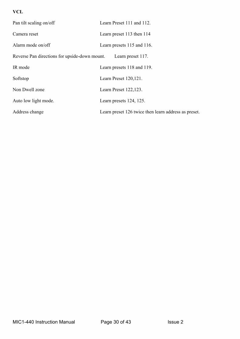
VCL Pan tilt scaling on/off Learn Preset 111 and 112. Camera reset Learn preset 113 then 114 Alarm mode on/off Learn presets 115 and 116. Reverse Pan directions for upside-down mount. Learn preset 117. IR mode Learn presets 118 and 119. Softstop Learn Preset 120,121. Non Dwell zone Learn Preset 122,123. Auto low light mode. Learn presets 124, 125. Address change Learn preset 126 twice then learn address as preset.
MIC1-440 Instruction Manual Page 30 of 43 Issue 2
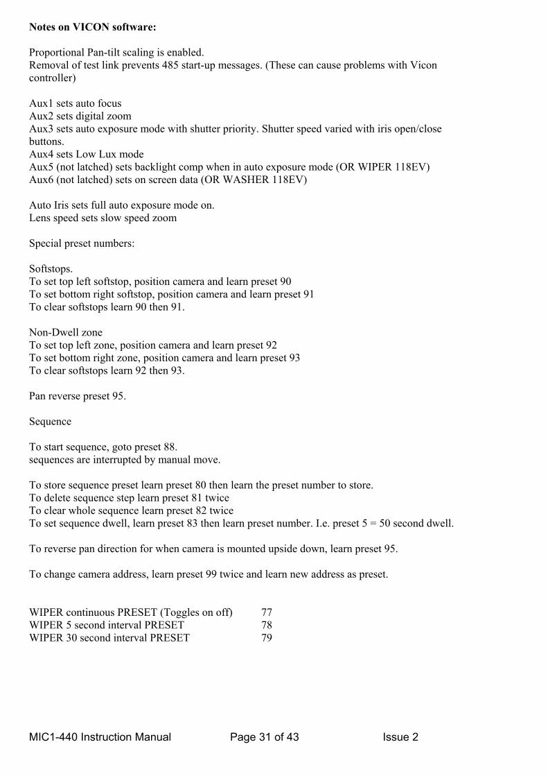
Notes on VICON software: Proportional Pan-tilt scaling is enabled. Removal of test link prevents 485 start-up messages. (These can cause problems with Vicon controller) Aux1 sets auto focus Aux2 sets digital zoom Aux3 sets auto exposure mode with shutter priority. Shutter speed varied with iris open/close buttons. Aux4 sets Low Lux mode Aux5 (not latched) sets backlight comp when in auto exposure mode (OR WIPER 118EV) Aux6 (not latched) sets on screen data (OR WASHER 118EV) Auto Iris sets full auto exposure mode on. Lens speed sets slow speed zoom Special preset numbers: Softstops. To set top left softstop, position camera and learn preset 90 To set bottom right softstop, position camera and learn preset 91 To clear softstops learn 90 then 91. Non-Dwell zone To set top left zone, position camera and learn preset 92 To set bottom right zone, position camera and learn preset 93 To clear softstops learn 92 then 93. Pan reverse preset 95. Sequence To start sequence, goto preset 88. sequences are interrupted by manual move. To store sequence preset learn preset 80 then learn the preset number to store. To delete sequence step learn preset 81 twice To clear whole sequence learn preset 82 twice To set sequence dwell, learn preset 83 then learn preset number. I.e. preset 5 = 50 second dwell. To reverse pan direction for when camera is mounted upside down, learn preset 95. To change camera address, learn preset 99 twice and learn new address as preset. WIPER continuous PRESET (Toggles on off) 77 WIPER 5 second interval PRESET 78 WIPER 30 second interval PRESET 79
MIC1-440 Instruction Manual Page 31 of 43 Issue 2
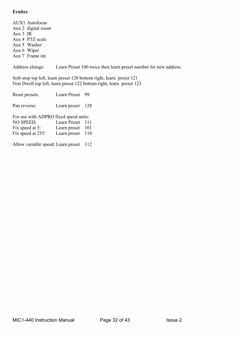
Ernitec AUX1 Autofocus Aux 2 digital zoom Aux 3 IR Aux 4 PTZ scale Aux 5 Washer Aux 6 Wiper Aux 7 Frame int. Address change. Learn Preset 100 twice then learn preset number for new address. Soft-stop top left, learn preset 120 bottom right, learn preset 121 Non Dwell top left, learn preset 122 bottom right, learn preset 123 Reset presets. Learn Preset 99 Pan reverse: Learn preset 128 For use with ADPRO fixed speed units: NO SPEED. Learn Preset 111 Fix speed at 5: Learn preset 101 Fix speed at 255: Learn preset 110 Allow variable speed: Learn preset 112
MIC1-440 Instruction Manual Page 32 of 43 Issue 2

Molynx Visilynx NOTE: Presets 1 to 30 are used as normal presets. DO NOT ATTEMPT TO USE PRESETS ABOVE 40. These are reserved for the following functions. Preset 32 is where the dome moves to in wash wipe mode. Program this preset to look at the washer nozzle. Preset 33 is where the dome moves when the tamper alarm is operated provided the dome is in auto alarm mode. Learn/Program/Store these preset numbers to activate special features. SOFTLIMIT_TOP_LEFT_PRESET 40 SOFTLIMIT_BOTTOM_RIGHT_PRESET 41 NOTE: If the dome only moves in one direction in pan, clear the softstops. To clear softstops, learn preset 40 then 41 without moving the dome. NONDWELL_TOP_LEFT_PRESET 42 NONDWELL_BOTTOM_RIGHT_PRESET 43 To clear the dwell zone, learn presets 42 then 43 without moving the dome. There are six independent tours. Switch the current tour by learning presets 51 to 56 SET_TOUR1_PRESET 51 SET_TOUR2_PRESET 52 SET_TOUR3_PRESET 53 SET_TOUR4_PRESET 54 SET_TOUR5_PRESET 55 SET_TOUR6_PRESET 56 AUTOFLIP_ON_PRESET 57 AUTOFLIP_OFF_PRESET 58 WASHWIPE_ON_PRESET 59 WASHWIPE_OFF_PRESET 60 PRIVACY_PRESET_START 61 PRIVACY_PRESET_END 75 PRIVACY_SET_WHOLE 75 PRIVACY_CLEAR_WHOLE 74 PRIVACY_UNCOVER_ALL 73 PRIVACY_REPLACE_ALL 72 PRIVACY_SHOW_STYLE 71 PRIVACY_HIDE_STYLE 70 PRIVACY_SET_STYLE 69 PRIVACY_SET_CENTRAL 68 PRIVACY_CLEAR_CENTRAL 67 PRIVACY_SHOW_CURSOR 66 PRIVACY_HIDE_CURSOR 65 PRIVACY_SAVE_PARAMETER 64 PRIVACY_LOAD_PARAMETER 63
MIC1-440 Instruction Manual Page 33 of 43 Issue 2
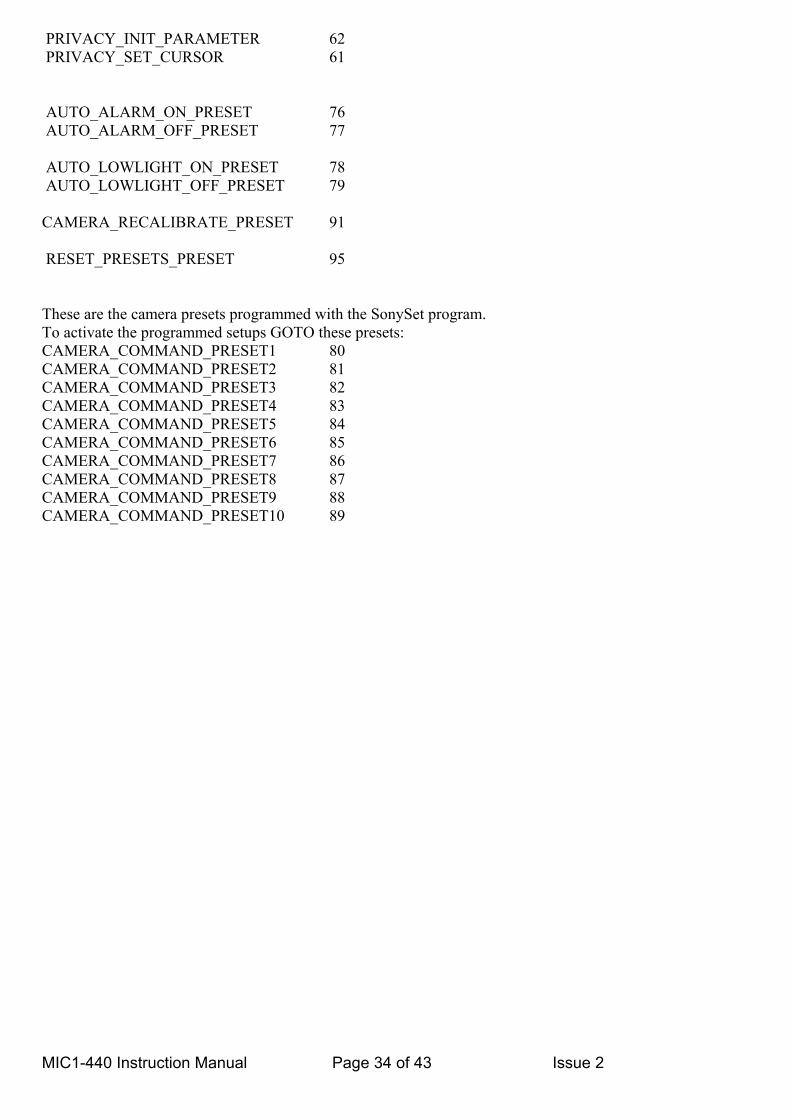
PRIVACY_INIT_PARAMETER 62 PRIVACY_SET_CURSOR 61 AUTO_ALARM_ON_PRESET 76 AUTO_ALARM_OFF_PRESET 77 AUTO_LOWLIGHT_ON_PRESET 78 AUTO_LOWLIGHT_OFF_PRESET 79 CAMERA_RECALIBRATE_PRESET 91 RESET_PRESETS_PRESET 95 These are the camera presets programmed with the SonySet program. To activate the programmed setups GOTO these presets: CAMERA_COMMAND_PRESET1 80 CAMERA_COMMAND_PRESET2 81 CAMERA_COMMAND_PRESET3 82 CAMERA_COMMAND_PRESET4 83 CAMERA_COMMAND_PRESET5 84 CAMERA_COMMAND_PRESET6 85 CAMERA_COMMAND_PRESET7 86 CAMERA_COMMAND_PRESET8 87 CAMERA_COMMAND_PRESET9 88 CAMERA_COMMAND_PRESET10 89
MIC1-440 Instruction Manual Page 34 of 43 Issue 2
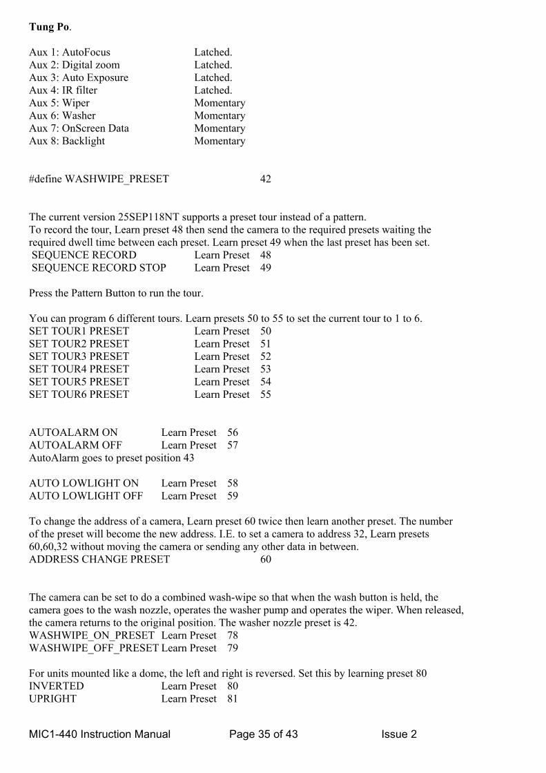
Tung Po. Aux 1: AutoFocus Latched. Aux 2: Digital zoom Latched. Aux 3: Auto Exposure Latched. Aux 4: IR filter Latched. Aux 5: Wiper Momentary Aux 6: Washer Momentary Aux 7: OnScreen Data Momentary Aux 8: Backlight Momentary #define WASHWIPE_PRESET 42 The current version 25SEP118NT supports a preset tour instead of a pattern. To record the tour, Learn preset 48 then send the camera to the required presets waiting the required dwell time between each preset. Learn preset 49 when the last preset has been set. SEQUENCE RECORD Learn Preset 48 SEQUENCE RECORD STOP Learn Preset 49 Press the Pattern Button to run the tour. You can program 6 different tours. Learn presets 50 to 55 to set the current tour to 1 to 6. SET TOUR1 PRESET Learn Preset 50 SET TOUR2 PRESET Learn Preset 51 SET TOUR3 PRESET Learn Preset 52 SET TOUR4 PRESET Learn Preset 53 SET TOUR5 PRESET Learn Preset 54 SET TOUR6 PRESET Learn Preset 55 AUTOALARM ON Learn Preset 56 AUTOALARM OFF Learn Preset 57 AutoAlarm goes to preset position 43 AUTO LOWLIGHT ON Learn Preset 58 AUTO LOWLIGHT OFF Learn Preset 59 To change the address of a camera, Learn preset 60 twice then learn another preset. The number of the preset will become the new address. I.E. to set a camera to address 32, Learn presets 60,60,32 without moving the camera or sending any other data in between. ADDRESS CHANGE PRESET 60 The camera can be set to do a combined wash-wipe so that when the wash button is held, the camera goes to the wash nozzle, operates the washer pump and operates the wiper. When released, the camera returns to the original position. The washer nozzle preset is 42. WASHWIPE_ON_PRESET Learn Preset 78 WASHWIPE_OFF_PRESET Learn Preset 79 For units mounted like a dome, the left and right is reversed. Set this by learning preset 80 INVERTED Learn Preset 80 UPRIGHT Learn Preset 81
MIC1-440 Instruction Manual Page 35 of 43 Issue 2

Digital zoom (Aux 2) can be disabled by learning preset 84. DIGITAL ZOOM DISABLE Learn Preset 84 DIGITAL ZOOM ENABLE Learn Preset 85 The pan and tilt speed can be scaled with zoom by learning preset 86. PTZ SCALE ON Learn Preset 86 PTZ SCALE OFF Learn Preset 87 SOFTLIMIT TOP LEFT Learn Preset 88 SOFTLIMIT BOTTOM RIGHT Learn Preset 89 NONDWELL TOP LEFT Learn Preset 90 NONDWELL BOTTOM RIGHT Learn Preset 91 SCAN LIMIT LEFT Learn Preset 92 SCAN LIMIT RIGHT Learn Preset 93 If the camera shows loss of focus, recalibrate it by learning preset 94. CAMERA RECALIBRATE Learn Preset 94 To change the scan speed, learn preset 95 followed by another preset. The second preset is the scan speed. The speed range is 1 to 40 SCAN SPEED SET Learn Preset 95 To start a scan GOTO preset 99. To start a frame scan (5 sec dwell at each end) GOTO preset 98. To stop a scan, Goto preset 96 or move the joystick. These preset codes are reserved for the Hi. Res. Privacy overlay card. #define PRIVACY_SET_WHOLE 75 #define PRIVACY_CLEAR_WHOLE 74 #define PRIVACY_UNCOVER_ALL 73 #define PRIVACY_REPLACE_ALL 72 #define PRIVACY_SHOW_STYLE 71 #define PRIVACY_HIDE_STYLE 70 #define PRIVACY_SET_STYLE 69 #define PRIVACY_SET_CENTRAL 68 #define PRIVACY_CLEAR_CENTRAL 67 #define PRIVACY_SHOW_CURSOR 66 #define PRIVACY_HIDE_CURSOR 65 #define PRIVACY_SAVE_PARAMETER 64 #define PRIVACY_LOAD_PARAMETER 63 #define PRIVACY_INIT_PARAMETER 62 #define PRIVACY_SET_CURSOR 61
MIC1-440 Instruction Manual Page 36 of 43 Issue 2

APPENDIX D
LIST OF APPROVED REPAIR CENTRES
REPAIR CENTRE ADDRESS TELEPHONE E-MAIL ADDRESS
FV CCTV LTD
Unit 1, Taplins Court Church Lane Hartley Wintney Hants RG27 8XU
0870 0113131 [email protected]
MIC1-440 Instruction Manual Page 37 of 43 Issue 2

APPENDIX E Installation Methods
MICI 440 Series CCTV Camera Head Exd IIC T6 ATEX approved. Installation using FVCCTV Non –armoured composite cable.
Item1 Camera Head Unit Exd IIC Ta –20 to 60ْ C P/no MIC 1-440 Item 02 Exd Cable Gland Hawke type 501/421/0/M20 P/no G1 Exd Size O (Supplied loose) Item 03 Composite Cable (Length to be specified) P/no FVCC Item 04 Exd Cable Gland Hawke type 501/421/0/M20 P/no G1 Exd Size O (Supplied loose) Item 05 Junction Box Exd (supplied loose) P/No JB EExd Item 06 Exd Barrier Glands (not supplied) P/no To be selected by installer to match incoming cables. Item 07 Mounting Bracket Heavy Duty (Not supplied) P/no FVMB
4
3 Length of cable to be specified by customer up to 20 meters maximum
6
1
2
7
PSU & Interface
5
EExd Junction Box
6
MIC1-440 Instruction Manual Page 38 of 43 Issue 2

MIC1-440 In
MICI 440 Series CCTV Camera Head Exd IIC T6 ATEX approved. Installation using FVCCTV Armoured composite cable.
1
4
3 Length of cable to be specified by customer up to 20 meters maximum
2
5
7
6
EExd Junction Box
PSU & Interface
Item1 Camera Head Unit Exd IIC Ta –20 to 60ْ C P/no MIC 1-440 Item 02 Exd Cable Gland Hawke type 501/453/RAC/0/M20 P/no G2 Exd Size O (Supplied loose) Item 03 Composite Cable (Length to be specified) P/no FVACC Item 04 Exd Cable Gland Hawke type 501/453/RAC/0/M20 P/no G2 Exd Size O (Supplied loose) Item 05 Junction Box Exd (supplied loose) P/No JB EExd Item 06 Exd Barrier Glands (not supplied) P/no To be selected by installer to match incoming cables. Item 07 Mounting Bracket Heavy Duty (Not supplied) P/no FVMB
struction Manual
Page 36
9 of 43 Issue 2

MICI 440 Series CCTV Camera Head Exd IIC T6 ATEX approved. Installation using Flexible Conduit.
Item1 Camera Head Unit Exd IIC Ta –20 to 60ْ C P/no MIC 1-440 Item 02 Exd Cable Gland KOPEX type HAM 0404 P/no G3 Exd (Supplied loose) Item 03 Flexible conduit KOPEX type FLT04 P/no FVFC04 Item 04 Exd Cable Gland KOPEX type HAM 0404 P/no G3 Exd (Supplied loose) Item 05 Junction Box Exd (supplied loose) P/No JB EExd Item 06 Exd Barrier Glands (not supplied) P/no To be selected by installer to match incoming cables. Item 07 Mounting Bracket Heavy Duty (Not supplied) P/no FVMB
4
3 Length of conduit to be specified by customer up to 20 meters maximum
6
1
2
7
PSU & Interface
5
EExd Junction Box
6
MIC1-440 Instruction Manual Page 40 of 43 Issue 2

DRAWINGS Fig 1. Four wire full duplex RS422 operation.
Fig 2. Two wire half duplex RS485 operation.
Fig 3. Two wire simplex RS485 operation
MIC1-440 Instruction Manual Page 41 of 43 Issue 2
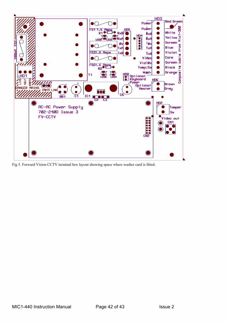
Fig 5. Forward Vision CCTV terminal box layout showing space where washer card is fitted.
MIC1-440 Instruction Manual Page 42 of 43 Issue 2
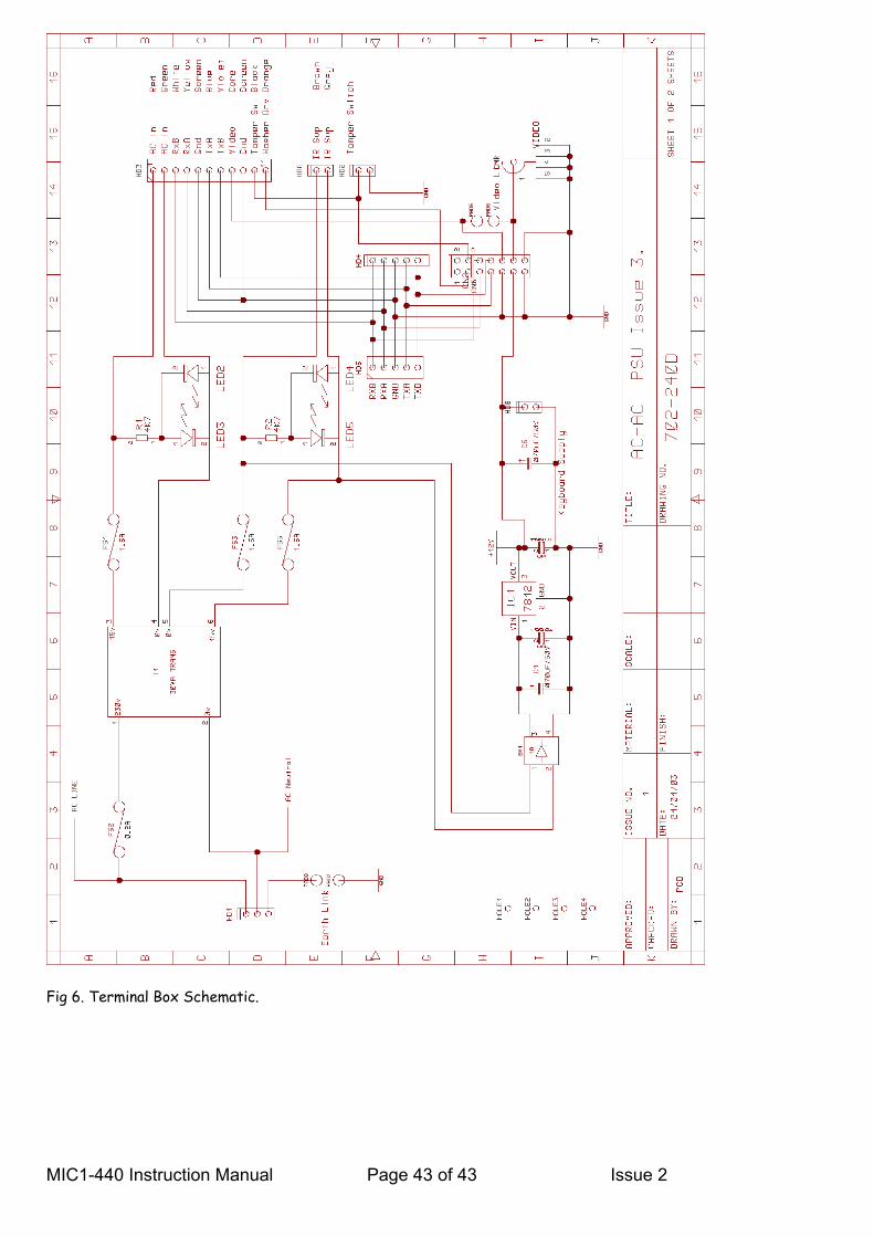
Fig 6. Terminal Box Schematic.
MIC1-440 Instruction Manual Page 43 of 43 Issue 2