mgra user guide - ontario user guide: a guide to using the ... standards development branch ......
TRANSCRIPT

MGRA User Guide: A Guide to Using the
“Approved Model” (November, 2016) When Submitting a
Modified Generic Risk Assessment (MGRA)
Standards Development Branch
Ministry of the Environment and Climate Change
PIBS # 8450e
«Cette publication hautement spécialisée n’est disponible qu’en anglais en vertu du règlement 441/97, qui en exempte
l’application de la Loi sur les services en français. Pour obtenir de l’aide en français, veuillez communiquer avec le
ministère de l’Environnement au 416-327-6949>.»

i
Disclaimer:
It should be noted that any description of the legislative and regulatory requirements given in this
Guide is for convenience only. A copy of the relevant legislation and regulations should be
obtained to determine the exact requirements, and a lawyer should be consulted on questions about
the application or interpretation of them.
Prepared by:
Ontario Ministry of the Environment and Climate Change Standards Development Branch
Toronto, Ontario, Canada
Original Publication Date: April 2011
Last Updated: November 2016
For more information:
Ministry of the Environment and Climate Change
Standards Development Branch
7th floor, 40 St. Clair Avenue West
Toronto, Ontario, M4V 1M2
www.ontario.ca/environment
PIBS 8450e
© Queen’s Printer for Ontario, 2016
ii
Table of Contents
1 Introduction to Modified Generic Risk Assessment ...................................................................... 1
2 Introduction to the User Guide for the Approved Model .............................................................. 1
2.1 New Features Introduced in Version 2 .................................................................................... 1 2.2 New MGRA Report Template Introduced in Version 2 .......................................................... 8 2.2.1 MGRA Report Template Organization ......................................................................... 8 2.2.2 Printing of the RA Report and Supporting Documentation .......................................... 9
2.3 Amending the Approved Model .............................................................................................. 9
3 Downloading and Setting up the Model ........................................................................................ 9
4 Running the Model and Selecting Model Options ....................................................................... 10
4.1 Entering Site Descriptors for Determining Table of Standards ............................................. 10 4.2 Entering Site Specific Input Parameters ................................................................................ 11 4.3 Viewing Modeling Results and Comparing with Site Concentrations .................................. 12 4.4 Adding Risk Management Measures and other Pathway Modifiers ..................................... 13
5 Consideration of Off-Site Receptors ............................................................................................ 17
6 Combining Risk Management Measures and other Pathway Modifiers Options in the Model:
Guidelines and Restrictions ......................................................................................................... 17
7 Calculating Soil Vapour Screening Levels .................................................................................. 22
8 Using Updated TRVs Published by the Ministry ........................................................................ 24
9 COCs with Hazard Quotient (HQ) other than 0.2 ........................................................................ 24
9.1 Trichloroethylene (TCE) at Non-Potable Sites ...................................................................... 25
9.2 Petroleum Hydrocarbons (PHC) ............................................................................................ 25
10 Using the Approved Model in a Tier 3 Risk Assessment ............................................................ 25
11 Risk Characterization ................................................................................................................... 25
12 Limitations of the Approved Model ............................................................................................ 28
12.1 Limitations Related to Generic Assumptions: ................................................................. 28 12.2 Limitations Related to MGRA Conceptual Site Model (CSM) ...................................... 29
13 Submitting the MGRA ................................................................................................................. 29
Appendices
Appendix 1 Determination of Soil Type
Appendix 2 Maps Showing “Number of Frozen Ground Days Per Year”
Appendix 3
Chart to identify which Tier 2 input parameters affect which pathways (subsurface
transport components)
Appendix 4 Tier 2 Option: Modified Ecological Protection (MEP)
Appendix 5 Modified Subsurface Worker Protection
Appendix 6 Process for Modifying the Solubility Component Value for Petroleum
Hydrocarbons (PHCs) F1 and F2 in the Modified Generic Risk Assessment
(MGRA) Approved Model
Appendix 7 Vapour Attenuation Multiplier Ceilings Applied to Storage Garages Considered
As Vapour Intrusion Risk Management Measures (RMMs) within the Modified

iii
Generic Risk Assessment (MGRA) Approved Model
Appendix 8a Soil Vapour Intrusion Mitigation Systems (SVIMS) Considered As Vapour
Intrusion RMMs within the Modified Generic Risk Assessment (MGRA)
Approved Model
Appendix 8b
Guide to Performance Verification and Monitoring of Soil Vapour Intrusion
Mitigation Systems (SVIMS)
Appendix 9 MGRA Risk Management Measures

1
Modified Generic Risk Assessment (MGRA) User Guide: A Guide to
Using the “Approved Model” When Submitting an MGRA
1 Introduction to Modified Generic Risk Assessment
The Modified Generic Risk Assessment (MGRA; also referred to as “Tier 2”) provides a
streamlined approach for developing property specific standards (PSS) under Ontario Regulation
153/04 (Records of Site Condition (RSC) – Part XV.1 of the Act), made under the Environmental
Protection Act (the Regulation). This streamlined process uses the “Approved Model,” which is
based on the model (a system of interconnected Excel spreadsheets) that was used to develop the
generic site condition standards (Soil, Ground Water and Sediment Standards for Use Under Part
XV.1 of the Environmental Protection Act - dated April 15, 2011).
The Approved Model enables a Qualified Person (QP) entitled to prepare or supervise a risk
assessment (QPRA, as described in section 6 of the Regulation) to develop PSS quickly and easily.
The Approved Model permits users a limited ability to modify physical site characteristics (e.g.,
distance to surface water body), modify certain pathways (e.g., ½ solubility and S3 for subsurface
workers) supported by analytical results/data and opt into risk management measures (RMMs)
(e.g., surface capping), which are developed by the Ministry of the Environment and Climate
Change (ministry). For these reasons, the ministry provides a streamlined process for acceptance of
PSS that are developed in risk assessments (RAs) that rely solely on the Approved Model.
2 Introduction to the User Guide for the Approved Model
The following is a suggested step-by-step guide for using the Approved Model when submitting an
MGRA to the ministry for review. The updated Approved Model is available on the ministry’s
website, and is dated (November 2016).
Although the Approved Model is relatively user friendly, there are some aspects for which
guidance may assist the user considerably in generating the appropriate PSSs.
This User Guide assumes that a QP has already conducted or supervised and completed the phase
one and two environmental site assessments (ESAs) in accordance with the requirements of the
Regulation. Any work needed to modify an assumption within the model must be done in
accordance with the Regulation (i.e., sections 41, 42 and Table 4 of Schedule E), and must be
completed before the MGRA is submitted. The Approved Model may be used at various stages of
an RA for other purposes, such as project planning.
2.1 New Features Introduced in Version 2
The Approved Model was first published for use in RAs in July, 2011. Users could modify 11 site
specific parameters (e.g. distance to down-gradient surface water body, depth to highest annual
water table, fraction of organic carbon, etc.). Specific phase two ESA work must be carried out
(Schedule E, Table 4) to support modifying these parameters from the default values. Users could

2
also opt into six (6) RMMs [three (3) caps and three (3) building restrictions] in order to develop
higher PSSs, which would still provide the same protection for human health and the environment
as the generic site condition standards (generic standards). Two (2) pathway modifiers (modified
ecological protection and soil vapour screening levels) were also available in the original Approved
Model.
In the years since the Approved Model was first published, the ministry has worked closely with a
technical advisory body made up of experienced environmental professionals and industry
representatives in order to develop new model features to promote more efficient brownfield
redevelopment while maintaining the protection of the environment and human health. Version 2
is designed to allow a greater number of sites across the province to qualify for this streamlined RA
process. These changes provide a greater number of options for modifying component values, make
the model more user friendly, correct errors in the model discovered since the model was first
published, and update the model to reflect current science while continuing to provide the same
level of environment and human health protection.
For a summary of the effects of all Approved Model options now available, please see the
following table.

3
Name of RMM or
Pathway Modifier
Effect of Pathway Modifier/RMM on
Component Values
Requirements &
Precluding Conditions
Applicability
I/C/C R/P/I
(General)
Modified Ecological
Protection (MEP)
Pathway Modifier
Uses industrial values x 1.9 for plants and soil
organisms (PSO) and 1000x for mammals and birds
(M&B)
Need to include
statement in RSC that
MEP is being used.
Yes Yes
Shallow Soil Cap
Barrier RMM (>50cm)
Uses industrial values x 1.9 for PSO and 1000x for
M&B;
S3 (subsurface contact) replaces S1/S2 (direct
contact with surface soil);
Eliminates S-Nose
Limited to I/C/C sites
only Yes No
Fill/Hard Cap Barrier
(1.0 metre or specified
greater thickness)
RMM
Uses industrial values x 1000 for PSO & 1000X
M&B;
S3 (subsurface contact) replaces S1/S2 (direct
contact with surface soil);
Eliminates S-Nose
None Yes Yes
Modified Subsurface
Worker Protection
Pathway Modifier
Multiplies S3 by 100x
(if leachate comparisons meet criteria for any
inorganic contaminant of concern (COCs))
Cap must have a
thickness of 1.5m.
Complete the relevant
part of the MGRA
section in the RA Pre-
Submission Form;
For inorganic COCs:
requires leachate testing
for some COCs
Must have HASP
Yes Yes
Building with Storage
Garage (intermittent 3.9
L/sec/m2) RMM
1 -
R/P/I Property Use (Developmental COC):
Multiplies S-IA and GW2 by 12x for
Trichloroethylene (TCE) and by 2x for other
developmental COC
Complete the relevant
part of the MGRA
section in the RA Pre-
Submission Form (re:
modifying GW2)
No Yes
R/P/I Property Use (Non-Developmental COCs): No Yes
1 To see the rationale for the multiplier ceilings shown for the “Building with a Storage Garage” RMM, please see Appendix 7. Please also note that “intermittent
ventilation” is the default scenario assumed in the Ontario Building Code. More information is included in Appendix 7.

4
Name of RMM or
Pathway Modifier
Effect of Pathway Modifier/RMM on
Component Values
Requirements &
Precluding Conditions
Applicability
I/C/C R/P/I
(General)
Multiplies S-IA and GW2 by 200x
If there is a Storage
Garage occupying the
First Storey of the
building, it cannot be
double counted as both a
“Building with No First
Storey R/P/I Use RMM”
and a “Storage Garage
RMM”
I/C/C Property or First Storey Use (Developmental
COC):
Multiplies S-IA and GW2 by 6x for TCE
Yes No
I/C/C Property or First Storey Use (Non-
Developmental COC):
Multiplies S-IA and GW2 by 50x
Yes No
Building with Storage
Garage (continuous 3.9
L/Sec/m2) RMM -
R/P/I Property Use (Developmental COC):
Multiplies S-IA and GW2 by 200x for TCE and by
30x for other developmental COCs
No Yes
R/P/I Property Use (Non-Developmental COCs):
Multiplies S-IA and GW2 by 200x No Yes
I/C/C Property or First Storey Use (Developmental
COC):
Multiplies S-IA and GW2 by 30x for TCE and by
7x for other developmental COCs
Yes No
I/C/C Property or First Storey Use (Non-
Developmental COC):
Multiplies S-IA and GW2 by 100x
Yes No
Building with Storage
Garage (continuous 10
L/sec/m2) RMM-
R/P/I Property Use (Developmental COC):
Multiplies S-IA and GW2 by 200x for TCE and by
70x for other developmental COCs
No Yes
R/P/I Property Use (Non-Developmental COCs):
Multiplies S-IA and GW2 by 200x No Yes
I/C/C Property or First Storey Use (Developmental
COC):
Multiplies S-IA and GW2 by 70x for TCE and by
15x for other developmental COCs
Yes No
I/C/C Property or First Storey Use (Non-
Developmental COC):
Multiplies S-IA and GW2 by 200x
Yes No
Building Prohibition
RMM
Effectively S-OA replaces S-IA;
Multiplies GW2 by 200x
Cannot be combined
with other building
related RMMs;
Yes Yes

5
Name of RMM or
Pathway Modifier
Effect of Pathway Modifier/RMM on
Component Values
Requirements &
Precluding Conditions
Applicability
I/C/C R/P/I
(General)
Complete the relevant
part of the MGRA
section in the RA Pre-
Submission Form (re:
modifying GW2)
Passive Soil Vapour
Intrusion Mitigation
System (SVIMS)
RMM2
Multiplies S-IA and GW2 by 100x
Limited to I/C/C with
slab on grade built form;
Complete the relevant
part of the MGRA
section in the RA Pre-
Submission Form (re:
modifying GW2)
Yes No
Active Soil Vapour
Intrusion Mitigation
System (SVIMS) RMM
Multiplies S-IA and GW2 by 200x
Limited to R/P/I (with
Property Management
Oversight), and to I/C/C;
Complete the relevant
part of the MGRA
section in the RA Pre-
Submission Form (re:
modifying GW2)
Yes
Only with
Property
Management
Oversight as
defined by the
CPU
Building with No First
Storey Residential,
Institutional or
Parkland Use RMM
Uses I/C/C S-IA and GW2 values
No R/P/I property use
on first storey of
building;
No Industrial property
use at the site;
If the building also
includes a basement or
storage garage, the depth
to ground water used in
the model should reflect
post-development
Yes Yes
2 To see the rationale for the multiplier ceilings shown for the SVIMS RMMs, and to see guidance on monitoring performance, please see Appendix 8

6
Name of RMM or
Pathway Modifier
Effect of Pathway Modifier/RMM on
Component Values
Requirements &
Precluding Conditions
Applicability
I/C/C R/P/I
(General)
conditions;
Complete the relevant
part of the MGRA
section in the RA Pre-
Submission Form (re:
modifying GW2)
Soil Vapour Screening
Level (met for soil
source) Pathway
Modifier
Multiplies S-IA by 1000x
Table 4 Sch. E
requirements for
Environmental Site
Assessment (ESA)
Yes Yes
Soil Vapour Screening
Level (met for ground
water source) Pathway
Modifier
Multiplies GW2 by 200x
Table 4 Sch. E
requirements for ESA;
Complete the relevant
part of the MGRA
section in the RA Pre-
Submission Form (re:
modifying GW2)
Yes Yes
Building with
Minimum First Storey
Ceiling Height
Requirement RMM
Based on height of first storey, dilution factor for
building (proportional to ceiling height);
Multiplies S-IA and GW2 up to 2X
Limited to I/C/C Yes No
No Ground Water Use
RMM
Uses non-potable component values (CVs);
Example : Table 3 (non-potable) CVs replace Table
2 (potable) CVs
Complete the relevant
part of the MGRA
section in the RA Pre-
Submission Form
(requires pre-consult
with District Office)
Yes Yes
Modify Solubility
Pathway Modifier
PHC F2 Solubility CV: 150 µg/L --> 2,500 µg/L
PHC F1 Solubility CV: 1,900 µg/L --> 27,000 µg/L.
Complete the relevant
part of the MGRA
section in the RA Pre-
Submission Form;
See guidance in
Appendix 6
Yes Yes

7
Note: Where the RA includes use of the Passive SVIMS or the Active SVIMS RMM, as applicable, the RA should include a statement
indicating that a Licenced Professional Engineer knowledgeable in the design and operation of such soil vapour intrusion mitigation
systems has reviewed the requirements of these RMMs in the context of the conditions of the Property and agrees that the SVIMS RMM
to be used can be properly implemented at the Property.

8
2.2 New MGRA Report Template Introduced in Version 2
A new MGRA Report Template has been added into the Approved Model (Excel spreadsheet) for
Version 2. Adding the template tabs directly into the Approved Model means that many of the
tables summarizing model inputs and outputs are now auto-populated by the model, once the QP
has selected COCs, inserted site specific characteristics, RMMs and pathway modifiers. This new
template was created in order to streamline reporting by the QP and reviewing by the ministry. To
visually locate the tabs more easily, the tabs are highlighted blue.
2.2.1 MGRA Report Template Organization
The new MGRA Report Template is broken up into several tabs (identified by blue shading):
1. “MGRA Report Template” tab contains most of the fixed text previously included in
the Word version of the template. There are several instances of bright green shaded
cells meant for QP input (e.g., Checklist of Mandatory Appendices and Supporting
Documents; current property use field). This tab maintains section numbering that
corresponds to the headings and requirements contained in Schedule C, Table 1
(Mandatory Requirements for RA Reports).
2. Certifications tab for printing and signing by the QP.
3. Property Specific Standards tab through to RMM tab: these tabs include numbered
tables corresponding to the sections in the “MGRA Report Template” tab. Wherever
possible, the values in these tables are populated automatically by the model. There
are also bright green shaded cells that are for direct user input, and paler green shaded
cells that have pull down menus that pop up when the arrow on the right side of the
box is clicked.

9
2.2.2 Printing of the RA Report and Supporting Documentation
Now that the MGRA Report Template has been incorporated into the Approved Model, there is no
need to print out the Tier 2 Input tab as part of the MGRA submission.
The proponent should provide, as part of the RA submission, the following items electronically:
Approved Model (including all site specific inputs and MGRA Report Template tabs
completed by the QP).
RA Pre-Submission Form.
The proponent should provide, as part of the RA submission, the following items in hard copy (4
copies):
Report cover page.
Phase two conceptual site model (CSM).
RA Pre-Submission Form signature page(s).
MGRA Report Template certifications tab (with QP signatures).
The complete MGRA submission should be mailed to the ministry.
2.3 Amending the Approved Model
The amended version of the Approved Model came into effect November 2016 [method: Decision
Notice Posted on the Environmental Registry]. The original version of the model will remain
publicly available to view, but not to use.
3 Downloading and Setting up the Model
The “Approved Model” can be downloaded from the following website. The model is designed to
work on Microsoft Excel 2003 (or later). Note that the print screen from this user guide is based on
the Microsoft Excel 2010 version. The ministry cannot assure users that results from its use on
other programs will be the same as those produced by Excel.
www.ontario.ca/environment-and-energy/brownfields-redevelopment
** Be sure that “Analysis Tool Pak” and “Solver Add -in” are installed in Excel
- Go to File>Options>Add-Ins (or in earlier versions of Excel: Tools>Add-Ins), then
check the appropriate boxes, and click OK
** Also be sure to click the “Enable Content” box in the yellow security warning band at the top of
the workbook when it opens.

10
4 Running the Model and Selecting Model Options In the following sections you will find a sequence of steps that follows a progression from less to
more complex MGRAs. For example, the least complex MGRAs change only measurable
parameters such as the distance to the nearest surface water body, and do not require RMMs and
are discussed first. More complex MGRAs can combine changes in site specific parameters,
RMMs, and additional site investigation to support pathway modifiers. Once you are familiar with
the model, you likely wouldn’t use the model in this step-wise fashion, but when you are learning
the model’s features, it’s helpful to add layers of complexity in a logical way.
4.1 Entering Site Descriptors for Determining Table of Standards
Step 1. Open “Approved Model” and click on the “Tier 2 Input “ tab
The cells that are highlighted in green are cells where the user can input information. The
bright green shaded cells are for direct numeric user input, and the paler green shaded cells
have pull down menus that pop up when the arrow on the right side of the box is clicked.
Check Site Descriptors in cells B3-B8 to be sure that the descriptions match the RA
property. These fields are used to select the applicable table of site condition standards
(SCS). To change a description, click on the appropriate cell, then click on the down arrow
on the right end of the box and choose the description that is appropriate for the site.
Explanations of these site descriptors are available in the document “Records of Site
Condition: A Guide on Site Assessment, the Cleanup of Brownfield Sites and the Filing of
Records of Site Condition“, which can be found at www.ontario.ca/environment-and-
energy/brownfields-redevelopment
(4728e)

11
4.2 Entering Site Specific Input Parameters
Step 2. Once the appropriate site descriptors are selected, start entering the relevant site data in cells
B12 – B26. If the data entered is outside of the acceptable range (cells in yellow, F12-G26),
the warning “INVALID” will be displayed and the cell will be highlighted in red. The Tier
1 (SCS) default values are given in cells I12 to J26 (also in yellow highlight). Once a value
changes from the default, so long as it is within the acceptable range, it is displayed in
italics.
* If there are site properties described in cells A12 –A26 of the Tier 2 Input tab for which
no measurements have been conducted, you may wish to check Appendix 3 to determine if
you can benefit from measuring them and using them in the Tier 2 process. The possibility
of producing a less stringent Tier 2 number exists if there is a check mark in Appendix 3
against the measured parameter for the particular driver that is driving your PSS.
For sites where the overall soil texture is medium/fine, be sure to enter the appropriate data
in Cells C16 – C20 (rather than B16 – B17 and B19 – B20, which are for coarse texture
soils). Note that cells B19-C20 and B21 are changed using the pull down menus to choose
the appropriate soil type or frozen days. For determination of the Soil Type, use the
measured sand, silt and clay contents from the site in conjunction with the information in
Appendix 1 of this document. If your goal is to develop PSS (as opposed to calculating soil
vapour screening levels) be sure to enter the appropriate value for the “Property Soil Type”,
as opposed to “Area Soil Type”. For determination of which value to use for Frozen
Ground Days, follow the requirements set out in sections. 41, 42 and Table 4, Schedule E of
the Regulation, and round it to the nearest tens or use the maps included in Appendix 2 of

12
this document. When using Appendix 2, if it is uncertain as to which of two zones your site
falls, use the higher (more conservative) of the two numerical values.
*Note that none of the four cells (B19-C20) for Soil Type can include either of the terms
“Generic Coarse” or “Generic Medium/Fine” if you want the soil vapour screening levels
(SVSLs) to be calculated. These two Soil Types are not options for Tier 2 when SVSLs are
being generated. There should be a reasonable correspondence between the Soil Types and
the Site Soil Texture, or the QP should have a full understanding and explanation as to the
reasons why they do not correspond reasonably well. All Phase Two ESAs upon which
MGRA are based should follow sections 41, 42 and Table 4 of Schedule E of the
Regulation.
*Note that if the Area Soil Type for the SVSL is considered “fine/medium” textured soil
based on grain size analysis, the QP will need to ensure that the “Site Soil Texture” in Cell
B4 is changed to correspond to “medium/fine” texture for property SVSL calculations.
4.3 Viewing Modeling Results and Comparing with Site Concentrations
Step 3. After all of the available Tier 2 inputs have been populated, you can review the results that
the spreadsheet has generated and compare them with the maximum concentrations
measured on the site3. To do this, click on Cell A77 and then click on the down arrow at the
right end of the cell and choose a chemical identified as a COC at the site. Repeat in cells
A78 to A101 for all COCs on site.
Note 1 – This spreadsheet allows for 25 COCs. If there are more than 25 COCs at the site,
you should consider whether an MGRA approach is appropriate given the potential
complexity of the site. If needed, you can run the model again for the remainder of the
COCs, saving with a different file name.
Note 2 – rather than entering all COCs manually using the drop-down menu, you may prefer
to try these tips to help populate your COC list more quickly:
Tip 1: enter a space before AND after the COC name, e.g. _benzene_, and make
sure you type the same name as indicated in the MGRA, e.g. “Dichlorobenzene, 1,2-
” NOT “1,2, Dichlorobenzene”
Tip 2: just copy and paste the COC name from the other tab, e.g. “ Phys_chem
&Tox”
The initial soil and ground water criteria generated by the spreadsheet will appear in cells
B77-G101.
3 If your property is both shallow soil (typically Table 6/7) and within 30 metres of the nearest water body (Table 8/9),
you may be wondering how the PSS are calculated. They are based on the lower of the Table 6/7 and 8/9 component
values. Please see the tables labelled 10/11 in the “Primary Tables of Standards” tab for a summary of results.

13
Step 4. Your actual (measured) site concentrations for soil and groundwater are added to the
spreadsheet in cells I77-K96, and your calculated reasonable estimate of the site maximum
(REM) are inputted into Cells L77-N101. Note that the estimate of the site max cannot
exceed 1.2 times the actual measured site max in an MGRA (a warning will pop up if it
does). Also note that delineation for all COCs must be complete before the MGRA is
submitted. If all COC REM concentrations are numerically lower than the respective values
calculated by the spreadsheet (B77-G101), then your site meets the Tier 2 PSSs, and you
may submit the RA to the ministry for review. The PSSs that you can use for submitting the
RA are displayed in Cells B108-D132. These values account for the REM.
4.4 Adding Risk Management Measures and other Pathway Modifiers
Step 5. If your site doesn’t meet the Tier 2 standards, then you may wish to take a look at the
Tables of Drivers (see screen shot below) to determine which component value is limiting
the PSS value4. To do this, at the bottom of the spreadsheet find the appropriate “Table of
Drivers” tab (soil or water (meaning ground water)), click on it, and then find the
appropriate Table of Standards, Soil Texture, and Land Use (Soils only) in rows 1 and 2.
Scroll down to the COC of interest, and determine which component is highlighted. The
highlighted cell indicates the driving component (note that if this component is below the
reporting limit or the background concentration they are also highlighted, and the criterion
is bumped up to the higher value). You may wish to note both the driving component and
the next lowest component value (the second driver) and compare both with your COC
concentration. Short descriptions of all the components are given at the end of Appendix 3.
4 For more information about the component values, and how they are used to develop standards, please see the
document “Rationale for the Development of Soil and Groundwater Standards for Use at Contaminated Sites in Ontario
(MOE 2011)” available at http://www.ontario.ca/environment-and-energy/brownfields-redevelopment

14
No Possibility of Change in Tier 2:
Solubility (with the exception of PHC F1 and F2, for which there is now site
characterization work that the QP can complete to modify this component value. This site
characterization work is described in Appendix 6).
Change from Measured Parameters (see Appendix 3)
S-IA, S-Odour, S-GW1, S-GW3, S-OA, GW2, GW2-Odour, GW3, Free Phase
Threshold
Note that meeting the Soil Vapour Screening Level (SVSL) generated for soil and
ground water could affect S-IA and GW2
Change from Pathway Modification (step 11)
Modified Ecological Protection: Plants and Soil Invertebrates, Mammals and Birds
Modify Solubility Component Values (PHC F1 and F2): solubility
Soil Vapour Screening Levels: S-IA, GW2 (described below)
Modified Subsurface Worker Protection: for addressing S3
Change from Risk Management; CPU typically issued (Appendices 5 to 8)
S-IA, S-IA (Odour), S1, S2, S-Odour, Plants and Soil Invertebrates, Mammals and
Birds, S3, GW1, GW2, GW-Odour.
Step 6. If the driving component is “Mammals and Birds” or “Plants and Soil Organisms”, then you
may wish to consider whether it would be appropriate for your site to use the “Modified
Ecological Protection” (MEP) option (by picking “Y” from the pull-down menu in cell
B30). This option will generate a higher number for the “Plants and Soil Organisms”

15
component, and effectively eliminate the “Mammals and Birds” component. An
acknowledgement that the option has been chosen must be placed on the RSC. For a full
description of this option, read Appendix 4 of this document.
Step 7. If your measured concentrations (for PHC F1 and F2) in ground water still exceed the Tier 2
PSS, and the driver is the solubility component value, then you may wish to opt into the
“Modify Solubility Component Values” (cell B40). Note: please see Appendix 6 for
guidance to assist proponents in conducting site characterization that is effective in
demonstrating that there is no evidence of free product, so that the solubility CV can be
modified in the MGRA. You may then answer the questions related to this option that are
found in the MGRA section of the RA Pre-Submission Form and provide supporting
documentation as part of the MGRA submission.
Note: To this point, none of the options chosen would typically result in the issuance of a
Certificate of Property Use (CPU), so if your property meets the Tier 2 PSSs at this stage and the
ministry accepts the RA, then a RSC could generally be filed without a CPU. However, all other
Tier 2 options (with the exception of Soil Vapour Screening Levels) described from the next step-on
would typically be associated with a CPU.
Step 8. If your site soil still doesn’t meet the Tier 2 standards and the driving component is any of
“Mammals and Birds”, “Plants and Soil Organisms”, S1, or S2, then you may wish to
consider the use of either a “Shallow Soil Cap (Cell B31)” (for industrial/commercial sites)
or a “Fill Cap” or “Hard Cap” (Cell B32). These RMMs (RMMs) are described on the
“RMM Descriptions” tab of the Approved Model (Excel). In the “Tier 2 Input”
spreadsheet, clicking on one of the RMMs hyperlinked in blue (A31-A43) will take you to
the appropriate description. Choose the option appropriate for your site by picking “Y” on
the pull down menu in Cells B31-B37 & B41- B43 of the Tier 2 Input spreadsheet.
Step 9. If your measured concentrations still exceed the Tier 2 PSS, and the driver is either S-IA or
GW2, then you may wish to consider:
“Building with Storage Garage” (i.e. ventilated parking garage) (cells B33);
“Building Prohibition” (if no enclosed buildings will be constructed at the site) (choose
cell B34 for either);
“Passive Soil Vapour Intrusion Mitigation System” (cell B35);
“Active Soil Vapour Intrusion Mitigation System” (cell B36);
“Building with no First Storey Residential, Institutional or Parkland Use5” (cell B37); or
“Building with Minimum First Storey Height Requirement” (cell B41).
Soil Vapour Screening Levels (not an RMM; described below)
Please see the summary table in Section 2.1 to see requirements and precluding conditions
for these options.
5 If the building also includes a basement or storage garage, the depth to groundwater used in the model should reflect
post-development conditions.

16
Step 10. If your measured concentrations still exceed the Tier 2 PSSs, and the driver is GW1
(for potable ground water site conditions), then you may wish to consider the “No Ground
Water Use” RMM (cell B42). Note however, that in order to check the “Y”, you must
answer the questions related to this RMM that are found in the MGRA section of the RA
Pre-Submission Form. Your responses to these questions should be used in pre-
consultation with the local District Office. Typically, answers to questions 2, 4 and 5 on
Page 26 of the RA Pre-Submission Form must be “yes” in order for this RMM to be used in
an MGRA. Note that when you select this option, you must return to cell B5 to change the
potability to “Non-potable”, which should now be the only option available in the dropdown
list. Please also note that one of the outcomes of the ministry’s review of the RA may still
be the conclusion that groundwater monitoring is warranted for the RA property, and that
the RA cannot, therefore, be classified as an MGRA, and may need to proceed as a
traditional “Tier 3” RA. The Approved Model can continue to be relied upon to develop
PSS, but the Director will review whether any selected RMMs are appropriate for the
property, as the RA is no longer considered an MGRA.
Step 11. If your measured concentrations still exceed the Tier 2 PSSs, and the driver is S3,
you may wish to opt into the “Modified Subsurface Worker Protection” pathway modifier
(cell B43). Note however that for inorganics (COCs without Koc values), in order to check
the “Y”, you must answer the questions related to this RMM that are found in the MGRA
section of the RA Pre-Submission Form, and should provide leachate testing results as part
of the MGRA. For details on the use of this pathway modifier, please refer to Appendix 5.
For inorganics, select the COCs from the drop down list in cells A62-A66. The
corresponding leachate criteria are generated in row B. Next, enter the leachate analysis
results in row C for comparison.

17
5 Consideration of Off-Site Receptors If you have used RMMs affecting the ground water for protection of drinking water pathway (GW1
pathway), or the ground water for protection of indoor air pathway (GW2 pathway) or soil vapour
screening for a ground water source, you should carefully consider the potential impact of ground
water travelling from the RA site to downgradient sites. The following MGRA options modify
GW1 and GW2:
Options that modify GW1:
o No Ground Water use RMM
Options that modify GW2:
o Building with Storage Garage RMMs
o Building Prohibition RMM
o Building with No First Storey Residential, Institutional or Parkland Use RMM
o Soil Vapour Intrusion Mitigation System RMMs
o Building with Minimum First Storey Ceiling Height Requirement RMM
o Soil Vapour Screening Level met for ground water source (pathway modifier)
Table 4-5 of the Human Health RA MGRA Report Template (Off-site – HH tab) is provided in
accordance with Mandatory Requirements for RA Reports (Schedule C, Table 1 of the Regulation)
and this section requires the QP to assess whether the proposed human health standards will likely
result in an exceedance of the applicable full depth Site Condition Standard at the nearest off-site
human receptor. You must also answer the questions related to options that modify GW1 and GW2
found in the MGRA section of the RA Pre-Submission Form, and should use these questions as a
basis to consult with the local District Office about your assessment of the likelihood of off-site
impacts.
6 Combining Risk Management Measurements and other Pathway
Modifiers Options in the Model: Guidelines and Restrictions Here are restrictions on how RMMs, Modified Ecological Protection (MEP) and Soil Vapour
Screening Levels (SVSLs) can be combined. In general, most options can be combined in the
model, but there is not always an advantage to combining them in terms of generating less stringent
standards. Please see the bullets and summary table below to see the effects of (and restrictions
for) combining options in the Approved Model.
MEP can be combined with anything, but would provide no extra benefit if a cap is
selected
SVSLs can be combined with anything. There is no numerical advantage in the
proposed PSS to doing so; however, the screening level that the measured soil vapour
concentration are compared to will be increased if soil vapour RMMs are selected
“Fill Cap Barrier” & “Hard Cap Barrier” can be combined with one another
If a “Shallow Soil Cap Barrier” is combined with other caps at a site, only the “Shallow
Soil Cap Barrier” multipliers can be used
“Shallow Soil Cap Barrier” can only be used if the intended and actual property use is
industrial/commercial/community

18
Caps can generally be combined with other RMMs such as the RMMs affecting the
vapour intrusion pathway (subject to the restriction for “Shallow Soil Cap” given above)
“Active Soil Vapour Intrusion Mitigation Systems (SVIMS)” can only be used if (a) the
intended and actual property use is industrial/commercial/community, OR (b) if the
intended and actual property use includes residential/parkland/institutional, the Building
must be multi-storey and multi-unit, and must have Property Management Oversight.
(For more information, please see the description of this RMM and the relevant
Definitions).
“Passive Soil Vapour Intrusion Mitigation System (SVIMS)” can only be used if
property use is industrial/commercial/community and the building type is slab on grade.
“Building Prohibition” cannot be used at sites that will have buildings, so it cannot be
combined with other building restrictions (e.g.: “Building with Storage Garage,”
“Building with no First Storey Residential, Institutional or Parkland Use,” “Building
with Minimum First Storey Ceiling Height Requirement.”)
Abbreviations used in the tables below
COC Contaminant of Concern
GW2 Ground water for the protection of Indoor Air
I/C/C Industrial / Commercial / Community (refers to least sensitive property use category)
M&B Mammals & Birds
PSF Pre-Submission Form
PSO Plants and Soil Organisms
R/P/I Residential / Parkland / Institutional (refers to a more sensitive property use category)
RSC Record of Site Condition
S-IA Soil for the protection of Indoor Air
S-OA Soil for the protection of Outdoor Air
SVIMS Soil Vapour Intrusion Mitigation System
SVSL Soil Vapour Screening Level

19
Effect on Multiplier Ceilings when MGRA Options are Combined
Options to address Ecological Pathways (PSO, M&B)
MEP Shallow Cap Hard/Fill Cap
Modified Ecological
Protection (MEP)
Uses industrial values x 1.9 for
PSO and 1000x M&B;
Need to include statement in RSC
that MEP option is used.
No value in combining MEP with
caps (but CPU typically required
for caps)
No value in combining MEP with
caps (but CPU typically required for
caps)
Shallow Soil Cap Barrier
RMM
No value in combining MEP with
caps (but CPU typically required
for caps)
Uses industrial values x 1.9 for
PSO and 1000x M&B;
Limited to I/C/C sites
Where shallow and hard/fill caps are
present on different areas of a
property, the shallow cap multiplier
ceilings are applied.
Hard/Fill Cap Barrier
RMM
No value in combining MEP with
caps (but CPU typically required
for caps)
Where shallow and hard/fill caps
are present on different areas of
the property, the shallow cap
multiplier ceilings are applied.
Uses industrial values x 1000 for
PSO & 1000 X M&B for R/P/I and
I/C/C
Options to address the Soil Contact Pathway (S1, S2, S3)
Shallow Cap Hard/Fill Cap MSWP
Shallow Soil Cap Barrier
RMM
S3 replaces S1/S2
Limited to I/C/C sites
Where shallow and hard/fill caps
are present on different areas of
the property, the shallow cap
multiplier ceilings are applied.
100x S3
Hard/Fill Cap Barrier
RMM
Where shallow and hard/fill caps
are present on different areas of the
property, the shallow cap multiplier
ceilings are applied.
S3 replaces S1/S2 100x S3
Modified Subsurface
Worker Protection
(MSWP)
N/A
1.5 m Fill/hard Cap RMM or
stratified standards must be in
place in order to use MSWP as
well as a HASP
100x S3
20
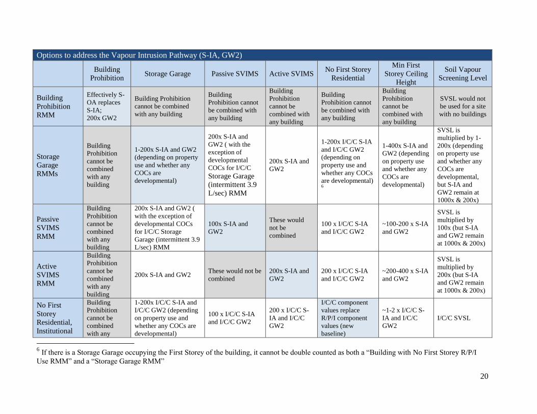
Options to address the Vapour Intrusion Pathway (S-IA, GW2)
Building
Prohibition Storage Garage Passive SVIMS Active SVIMS
No First Storey
Residential
Min First
Storey Ceiling
Height
Soil Vapour
Screening Level
Building
Prohibition
RMM
Effectively S-
OA replaces
S-IA;
200x GW2
Building Prohibition
cannot be combined
with any building
Building
Prohibition cannot
be combined with
any building
Building
Prohibition
cannot be
combined with
any building
Building
Prohibition cannot
be combined with
any building
Building
Prohibition
cannot be
combined with
any building
SVSL would not
be used for a site
with no buildings
Storage
Garage
RMMs
Building
Prohibition
cannot be
combined
with any
building
1-200x S-IA and GW2
(depending on property
use and whether any
COCs are
developmental)
200x S-IA and
GW2 ( with the
exception of
developmental
COCs for I/C/C
Storage Garage
(intermittent 3.9
L/sec) RMM
200x S-IA and
GW2
1-200x I/C/C S-IA
and I/C/C GW2
(depending on
property use and
whether any COCs
are developmental) 6
1-400x S-IA and
GW2 (depending
on property use
and whether any
COCs are
developmental)
SVSL is
multiplied by 1-
200x (depending
on property use
and whether any
COCs are
developmental,
but S-IA and
GW2 remain at
1000x & 200x)
Passive
SVIMS
RMM
Building
Prohibition
cannot be
combined
with any
building
200x S-IA and GW2 (
with the exception of
developmental COCs
for I/C/C Storage
Garage (intermittent 3.9
L/sec) RMM
100x S-IA and
GW2
These would
not be
combined
100 x I/C/C S-IA
and I/C/C GW2
~100-200 x S-IA
and GW2
SVSL is
multiplied by
100x (but S-IA
and GW2 remain
at 1000x & 200x)
Active
SVIMS
RMM
Building
Prohibition
cannot be
combined
with any
building
200x S-IA and GW2 These would not be
combined
200x S-IA and
GW2
200 x I/C/C S-IA
and I/C/C GW2
~200-400 x S-IA
and GW2
SVSL is
multiplied by
200x (but S-IA
and GW2 remain
at 1000x & 200x)
No First
Storey
Residential,
Institutional
Building
Prohibition
cannot be
combined
with any
1-200x I/C/C S-IA and
I/C/C GW2 (depending
on property use and
whether any COCs are
developmental)
100 x I/C/C S-IA
and I/C/C GW2
200 x I/C/C S-
IA and I/C/C
GW2
I/C/C component
values replace
R/P/I component
values (new
baseline)
~1-2 x I/C/C S-
IA and I/C/C
GW2
I/C/C SVSL
6 If there is a Storage Garage occupying the First Storey of the building, it cannot be double counted as both a “Building with No First Storey R/P/I
Use RMM” and a “Storage Garage RMM”

21
Options to address the Vapour Intrusion Pathway (S-IA, GW2)
Building
Prohibition Storage Garage Passive SVIMS Active SVIMS
No First Storey
Residential
Min First
Storey Ceiling
Height
Soil Vapour
Screening Level
or Parkland
Use RMM
building
Building with
Minimum
First Storey
Ceiling
Height RMM
Building
Prohibition
cannot be
combined
with any
building
1-200x ~1-2x S-IA and
GW2 (depending on
property use and
whether any COCs are
developmental)
~100-200 x S-IA
and GW2
~200-400 x S-
IA and GW2
~1-2 x I/C/C S-IA
and I/C/C GW2
~1-2 x S-IA and
GW2 [multiplier
is proportional to
ceiling height
(new baseline)]
SVSL is
multiplied by ~1-
2x;
~1-2 x S-IA and
GW2
Soil Vapour
Screening
Level (SVSL)
Would not be
used for a site
with no
buildings
SVSL is multiplied by
1-200x (depending on
property use and
whether any COCs are
developmental, but S-
IA and GW2 remain at
1000x & 200x)
SVSL is multiplied
by 100x (but S-IA
and GW2 remain at
1000x & 200x)
SVSL is
multiplied by
200x (but S-IA
and GW2
remain at 1000x
& 200x)
I/C/C SVSL
SVSL is
multiplied by ~1-
2x;
~1-2 x S-IA and
GW2
1000 x S-IA
200 x GW2
Options to address the Drinking Water Pathway (GW1)
No Ground Water Use (There are no other options for this pathway)
No Ground Water Use
RMM
Uses non-potable component
values (GW2 or GW3 rather
than GW1)

22
7 Calculating Soil Vapour Screening Levels This method offers an alternative approach to address exceedences of the S-IA and GW2 pathways
for volatile COCs. If any of the calculated reasonable estimate of the site maximum (REMs) (L77-
N101) for volatile chemicals exceed the respective values calculated by the spreadsheet (B77-
G101) and the driver is either S-IA or GW2, then you can calculate soil vapour screening levels and
compare them to your actual soil vapour measurements. Make sure that you have fulfilled all of the
requirements of the Regulation in relation to soil vapour sample collection, including the MGRA-
specific requirements found in Schedule E, Table 4. For general guidance on soil vapour
assessment, the QP should refer to the draft Technical Guidance: Soil Vapour Intrusion
Assessment, dated 2013 (or the most recent ministry guidance available).
Step 1. Begin by entering the names of the volatile chemicals for which soil vapour
measurements are available into cells A52-A57, and entering the depth to soil vapour
measurement (B26) and the corresponding Area Soil Type – vadose zone (B19 or C19) for
one of the soil vapour sampling locations on the site where soil vapour measurements were
made. The soil vapour screening levels, appropriate for the soil vapour sampling location at
a given depth to soil vapour measurement and to the site inputs currently in the spreadsheet,
will then appear in row B (that is, if the Area Soil Type cells (B19-C20) do not contain
either of the two generic Soil Types). These soil vapour criteria are specific to the
particular soil vapour sampling location and depth from which the soil vapour samples were
taken, and which is represented by the current Tier 2 input data that you have entered in the
spreadsheet. Be sure to separate areas that are ground water source areas from those that are
soil source areas such that you can properly later choose the appropriate measures in cells
B38 or B39. Repeat this process as many times as needed. You must develop soil vapour
screening levels for each sampling location and depth to soil vapour measurement (as
specified in Table 4, Schedule E of the Regulation) in which soil vapour measurements
were taken at the RA property.
*Note that if the Area Soil Type for the SVSL is considered “fine/medium” textured soil
based on grain size analysis, the QP will need to ensure that the “Site Soil Texture” in Cell
B4 is changed to correspond to “medium/fine” texture for property SVSL calculations.
Step 2. Check to be sure that the input parameters (especially soil type and depth below soil
surface to soil vapour measurement (B26)) are correct for that specific soil vapour sampling
location. You can consult Appendix 1 of this guide for determination of soil type. Within
the scope of MGRA, the depth below soil surface to soil vapour measurement should meet
the following:
To minimize the influence of atmospheric short-circuiting, the minimum depth
below soil surface to soil vapour measurement is 150 cm, as per Table 4 of Schedule
E; and,
To ensure that the collected soil vapour measurements are appropriate to assess the
vapour intrusion pathway for both existing building(s) (if present) and future
building(s) (e.g. with respect to vapour accumulation and increased advection
near/below the building foundation), soil vapour samples should be collected at least
100 cm below the base of the building foundation. For example, if the depth of the
subsurface structure (e.g. basement) is similar to the R/P/I default value (158 cm

23
below soil surface), soil vapour should be collected at 258 cm below soil surface or
deeper.
For future building(s), if the built form is unknown, it is unlikely that reliance on
soil vapour measurements is appropriate to support modification of vapour intrusion
component values.
If depths that are shallower than those noted above are entered, the cell (B26) will be
shaded red and the message “INVALID” will be shown.
Step 3. For the first sampling location (Area 1), copy the soil vapour screening level (Cells
B52-B57) to Cells D52 to D57 (highlight cells to be copied, right click, choose copy, move
pointer to D52, right click, choose “Paste Special”, then “Values”( this last part is critical,
otherwise you will get formulae rather than numbers, or you may alter the formatting).
Step 4. Now enter the maximum soil vapour measurement recorded for that specific soil
vapour sampling location and depth for the appropriate chemical in cells E52-E57. If a
maximum measured concentration exceeds the soil vapour screening level, it will be
highlighted in red.
Step 5. For the next sampling locations (Area 2 to 6), revise the Soil Type – vadose zone and
the depth to soil vapour measurement fields to match the identified characteristics at the soil
vapour sampling location and depth where soil vapour samples were taken and repeat the
previous steps, putting the results in the section of the spreadsheet for appropriate sampling
location (e.g., “Area 2”). Then repeat for other sampling locations. (This spreadsheet
allows for up to 4 sampling locations at a time)
Step 6. If, for a given COC, all soil vapour measurements, at all the required sampling
locations and depths, meet the appropriate calculated soil vapour screening levels, then you

24
may change the value in cells B38 and/or B39 (“soil vapour screening levels are met”), as
appropriate for the source of the soil vapours (soil source or ground water source), to a “Y”
(on the pull down menu). In most cases this effectively allows for the removal of the S-IA
and the GW2 pathways from the Tier 2 PSSs.
**You will have to keep track as to which COCs meet the soil vapour screening levels, and
be sure to use the results from checking “Y” in B38 or B39 only for those COCs that meet
all the soil vapour screening levels. You would need to uncheck the “Y” to derive the PSS
for those COCs which do NOT meet the soil vapour screening level.
** Before determining your PSSs, you must now go back and re-enter the “Property-wide
Soil Types”. If at this point all your REMs at the site meet the calculated criteria in cells
B77-G101, then your site meets the appropriate Tier 2 PSSs, and you may submit the RA to
the ministry for review. The “Proposed Property Specific Standards” that you can use for
submitting the RA are displayed in Cells B108-D132.
8 Using Updated TRVs Provided by the Ministry This option allows QPs to use ministry-provided toxicity reference values (TRVs) in an MGRA, as
soon as they are updated and available. Only TRVs provided by the ministry may be used in place
of the existing TRV. The ministry will make new TRVs available to QPRAs.
Step 1. Check for the new ministry TRV.
Step 2. Change the TRV and its reference in the appropriate cells in the TRV tab (columns C to V)
of the model. The changes will be highlighted in red.
Step 3. Go back to the Tier 2 Input tab, which will be displaying an error that notes the number of
changes that have been made in the TRV table. Change cell B69 to “Yes” from the pull
down menu to indicate that you have intentionally changed a TRV, at which point the error
note disappears.
Step 4. You can now view the updated PSS, which take into account the updated TRV.
9 COCs with Hazard Quotient (HQ) other than 0.2 Source allocation is applied in the derivation of human health component values (HHCVs) in order
to account for exposures to the same substance via multiple pathways of exposure. The use of
source allocation helps to prevent potential exposure from exceeding a tolerable daily intake (TDI)
or tolerable concentration (TC). A default Source Allocation Factor (SAF) of 0.2 is applied in the
derivation of most HHCVs for non-cancer. This means that one-fifth of the TDI or TC was
allocated for most component values, which translates to a target HQ of 0.2. There are some
exceptions, however, for which the target risk levels for HQ are set at different levels or applied in
a different way.

25
9.1 Trichloroethylene (TCE) at Non-Potable Sites
Trichlorethylene (TCE) is now recognized as having developmental effects, as well as carcinogenic
effects, and this is reflected in updated TRVs in Version 2 of the Approved Model. PSSs generated
based on the updated TRVs are lower than those generated using Version 1 of the Approved
Model. For this reason, the ministry undertook a review of assumptions, (specifically the potential
for concurrent exposure from multiple pathways) used in calculating CVs for TCE. The review
examined multimedia intakes of TCE for an adult and led to the conclusion that TCE intake from
ingestion of food, ingestion of ground water, and ingestion and dermal contact with soil are
negligible at non-potable sites when compared to TCE exposure via inhalation of indoor air (and
possibly also outdoor air). Given that the background indoor air concentration is estimated at
approximately half the inhalation TRV (e.g. 2.0 µg/m3), the use of an HQ of 0.5 is considered
appropriate for calculating vapour intrusion CVs for non-potable sites.
The updated HQ of 0.5 applies only at sites where a non-potable ground water condition is applied
(i.e. site ground water is not used as drinking water), or for sites using the “No Ground Water Use”
RMM. This is because the drinking water pathway is a significant pathway for potable drinking
water sites, and an HQ of 0.2 is still applied for S-IA and GW2 at potable drinking water sites.
9.2 Petroleum Hydrocarbons (PHC)
An HQ of 0.5 is used for all PHC fractions. This has not changed since Version 1 of the Approved
Model. For more information, please see the ministry’s Rationale for the Development of Soil and
Ground Water Standards For Use At Contaminated Sites in Ontario dated April 2011, Section 2.4.
10 Using the Approved Model in a Tier 3 Risk Assessment
Where there is a need to go beyond the approaches permitted within the Approved Model, a Tier 3
RA approach can be used to supplement the Tier 2 PSS. A proponent will be required to complete
and submit a Tier 3 RA to the ministry for review as per the traditional process. The Tier 3 RA can
utilize the PSS generated by the Approved Model, including the methodology and/or RMM’s relied
upon to develop the PSS by appending the Tier 2 RA report to the Tier 3 submission when
submitting to the ministry for review.
11 Risk Characterization
When an RMM has been used, it is necessary to report what the risk level would be if the RMM
were to fail. These risk levels are calculated in the Tier 2 spreadsheet in cells P77-BA101. Please
note that they no longer need to be calculated with all the RMMs turned off (set at N), unlike in
Version 1. Cells B36 and B37 can be set to Y for the risk calculations only if all of the Soil Vapour
Screening Levels were met for all soil vapour samples. The screenshot below shows the user input
area (note the invalid entry where a reasonable estimate of the site maximum entered is higher than
1.2 times the actual measured value) and the first part of the risk calculations. Determine the risk
level by looking under the appropriate risk management measure in Row 72. The cancer risk level

26
is given for carcinogens and the Hazard Quotient from each particular exposure component (e.g.
soil contact) for non-carcinogens.
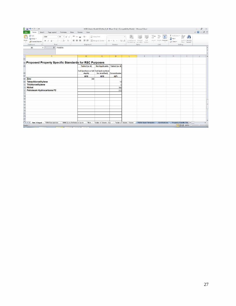
The next screenshot shows the area of the Tier 2 Input spreadsheet that displays the
final Proposed PSSs. There is also an area (cells B108-B132) that gives a quick reference
comparison for some common contaminants such that you can quickly see the effects of
your Tier 2 changes in comparison to the Generic Table 2 Residential coarse soil standards.
27

28
12 Limitations of the Approved Model
12.1 Limitations Related to Generic Assumptions
Any of the conditions for which the generic assumptions may not hold would result in a violation
of the assumptions behind the Approved Model as well. These conditions are reproduced from the
introduction to the Soil, Ground Water and Sediment Standards for Use under Part XV.1 of the
Environmental Protection Act, dated April 15, 2011 below.
Conditions can exist at a site for which the assumptions used to develop the generic criteria may
not be valid. The QP must ascertain that the site conditions are appropriate for use of the generic
standards such that he/she can be comfortable with signing the certifications on the RSC. To assist
the QP in recognizing the types of conditions that may be important in this respect the following
examples are given:
a) if the contaminated zone has a volume larger than 340 m3 or a source length or width greater
than 13 metres then all pathways which employ source depletion or ground water transport
(Soil to Nose, S-GW1, S-IA, S-GW3 and GW3 components of the standards) may be affected.
b) if a high permeability zone is present in the vadose zone which provides a direct preferential
pathway to the building then the soil properties assumed in the generic J&E modelling to
determine the S-IA and GW2 components of the standard may change.
c) if the annual average of the capillary fringe of the water table is < 0.8 metres from the outer
edge of the gravel crush of the building foundation or when there is less than one (1) meter of
between the top of the water table or soil contamination and the gravel crush layer, then the 10
x biodegradation factor assumed in the GW2 pathway for some VOCs may be non-
conservative.
d) if the average Organic Carbon content (foc) of soil above the water table is < 0.002 then
more contaminant may be in the water and gas phases than assumed in the generic standards.
f) if there is a continuous source of the contaminant then the pathways which assume a
depleting source (i.e., S-IA, S-GW1, and Soil to Nose) might be non-conservative.
g) if there is a surface water body that could be affected by the property from contaminant
migration via ground water, and the surface water has total hardness less than 70 mg/L (as
CaCO3) and/or has pH less than 6.7, the aquatic protection values for some metals and
pentachlorophenol may be non-conservative. In such cases, the QP may need to consider
whether a site-specific estimate of hardness and pH resulting from mixing of ground water and
surface water is needed to estimate an appropriate aquatic protection value for this site.
The existence of any of the above conditions does not necessarily indicate that the Tier 2 PSSs
are not valid for a given site. There are many interrelated parameters and factors that were used
in the development of the generic standards, and in many cases one factor, such as any of those
above, can be outweighed by differences in other factors in a manner that, overall, there is
sufficient natural protection provided by the site. In addition, it must also be considered that the
component that drives the standard may not be affected by the particular limiting condition
described above (e.g. a terrestrial ecological driver, but there are high permeable zones in the
29
vadose zone). The QP should consider these types of factors in assessing the appropriateness of
the use of the Tier 2 PSSs.
12.2 Limitations Related to MGRA Conceptual Site Model (CSM)
1. The Approved Model does not include a “ground water to plants and soil invertebrates”
pathway. When you have selected pathway modifiers that multiply ground water component
values (GW2 and GW3), consider whether the CSM used to develop the generic SCS is
appropriate. The generic GW3 value is a considered to be a reasonable surrogate for protection
of plant roots from ground water impacts. At greater distances to the nearest surface water
body, the GW3 can increase significantly in relation to the generic GW3 value.
2. The Approved Model does not include a vapour inhalation pathway for ground dwelling
mammals (such as groundhogs) or soil dwelling organisms (such as earthworms). When using
RMMs with large multipliers for S-IA (such as the “Building Prohibition” RMM), the QP
should consider whether or not ground dwelling mammals or soil dwelling organisms could be
adversely affected by the concentrations of volatiles substances remaining in the soil. The
ecological component values in the CSM used to develop the generic SCS do not have a
specific mechanism of protection for this pathway, and the assumption that the human health
vapour exposure pathways are adequate for ecological receptors is less likely to be valid at
higher multiples of the S-IA and GW2 component values.
13 Submitting the MGRA
Once you have completed the above steps and are satisfied with the RA you can submit it to the
ministry. Please see Section 2.2 regarding the MGRA report template.
For more information on Tier 2, contact the Streamlined Risk Assessment Coordinator at Standards
Development Branch of the Ontario Ministry of the Environment and Climate Change (E-mail:
[email protected]; Phone 416-327-5519).
30
Appendix 1 Determination of Soil Type
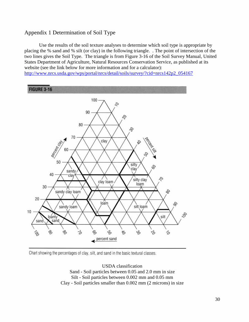
Use the results of the soil texture analyses to determine which soil type is appropriate by
placing the % sand and % silt (or clay) in the following triangle. . The point of intersection of the
two lines gives the Soil Type. The triangle is from Figure 3-16 of the Soil Survey Manual, United
States Department of Agriculture, Natural Resources Conservation Service, as published at its
website (see the link below for more information and for a calculator):
http://www.nrcs.usda.gov/wps/portal/nrcs/detail/soils/survey/?cid=nrcs142p2_054167
USDA classification
Sand - Soil particles between 0.05 and 2.0 mm in size
Silt - Soil particles between 0.002 mm and 0.05 mm
Clay - Soil particles smaller than 0.002 mm (2 microns) in size

31
Appendix 2 Maps Showing “Number of Frozen Ground Days Per Year”
A1 – Southern Ontario

32
A2 – Greater Toronto Area

33
B – Central Ontario

34
C – Northern Ontario

35
Appendix 3 Chart to identify which Tier 2 input parameters affect which pathways
(subsurface transport components)
Pathway\
Tier2 Input
Parameters
S-IA* S-
Odour
S-GW1 S-GW3 S-OA GW1 GW2 GW2-
Odour
GW3 Free Phase
Threshold
Distance to
surface water NA NA NA
NA NA NA NA
NA
Soil FOC –
water table to
soil surface
NA
NA NA NA NA
Soil FOC –
upper 0.5m NA
NA NA NA NA NA NA NA NA
Depth to
water table NA NA NA NA NA NA
NA NA
Property Soil
Type – vadose
zone
NA
NA
Property Soil
Type –
capillary
fringe
NA NA NA NA NA NA
NA NA
# Frozen Days NA
NA NA NA NA NA NA NA NA
Aquifer
horizontal
hydraulic
conductivity
NA NA NA
NA NA NA NA
NA
Aquifer
horizontal
hydraulic
gradient
NA NA NA
NA NA NA NA
NA
Aquifer dry
bulk density NA NA NA
NA NA NA NA
NA
Aquifer FOC NA NA NA
NA NA NA NA
NA
* Best method to do Tier 2 on S-IA pathway is using soil vapour screening methods as
described in the body of this document or by selection RMMs that mitigate the vapour
intrusion pathway.
NA = not applicable for pathway; = applicable for
pathway

36
Descriptions of all Components
GW1 – Ground water for drinking water purposes
GW2 – Ground water for protection from movement to indoor air
GW2-Odour – Ground water for protection from excessive odours
GW3 – Ground water for protection of aquatic life
S1 – Soil for protection of a residential receptor from direct contact with surface soil
S2 – Soil for protection from direct soil contact for a lower frequency and intensity exposure than
residential surface soil, such as for commercial or industrial scenarios where children are
not frequently present.
S3 – Soil for direct soil contact for a low-frequency, high-intensity, human health exposure
scenario without children present that is protective of a worker digging in the soil.
S-IA – Soil for protection of movement to indoor air and human exposure.
S- OA – Soil for protection of movement to outdoor air and human exposure
S-Odour – Soil for protection from excessive odours
S-GW1 – Soil for protection from movement to ground water for drinking water purposes
S-GW3 – Soil for protection from movement to ground water and then to aquatic life
Plants and Soil Organisms – Soil for protection against adverse effects to plants and soil dwelling
organisms
Mammals and Birds – Soil for protection against adverse effects through direct soil and food
ingestion to mammals and birds

37
Appendix 4 Tier 2 Option: Modified Ecological Protection (MEP)
1) What is the Tier 2 modified ecological protection (MEP) option?
In order to allow the development and application of less stringent PSS, current practice in
Ontario may be to remove ecological habitat to ensure no ecological species are present or exposed
to contamination. This practice results in the removal of habitat which, although degraded, could
and often does support a variety of ecological species. While redevelopment needs may drive the
removal of habitat, the ministry’s intent is to provide another option that will allow for greater
preservation of ecological habitat. The ministry has developed a “modified ecological protection
(MEP)” option within the Approved Model, which is intended to both promote brownfield
redevelopment and preserve existing and potential future ecological habitat. This means getting
more brownfield properties developed and providing developers a greener alternative to paving
over ecological habitat. The ministry will continue to look at new ways of promoting ecological
habitat preservation as part of brownfield redevelopment.
MEP is an option available to risk assessors within the MGRA process in Ontario that uses
less stringent ecotoxicity values to develop PSS. The use of the MEP option will allow for the
maintenance or establishment of natural habitat; habitat that is not comparable in quality to habitat
in an uncontaminated setting, but instead is habitat comprising of assemblages of species that are
adapted or less sensitive to the contaminants of concern at the property. Use of the MEP option
may result in impacts to some plants, soil organisms and wildlife that might reside in or frequent
the site. The MEP option does provide the same degree of protection to humans as the Tier 1
generic standards.
Under the MEP option, ecotoxicity values for mammals and birds are removed from the
modified generic model for both residential/parkland and commercial/industrial land uses.
Therefore no protection is provided for those ecological receptors under the MEP option. For
plants and soil invertebrates under both residential/parkland and commercial/industrial land uses,
the Tier 2 MEP option utilizes a multiplier (1.9 x industrial component value) that is equivalent to
the 75th
percentile value for each dose-response data set (developed for generic model values using
the CCME protocol weight-of-evidence procedure where resulting No Observable Effect
Concentration (NOEC) and Lowest Observed Effect Concentration (LOEC) data are ranked and
ranked percentiles are determined for each data point).
2) What is the purpose of the MEP option?
The ministry recognizes that maintaining natural environments on remediated brownfield
sites should be encouraged wherever possible. Soil standards at a brownfield site can often be
driven by ecological risks to soil-dwelling invertebrates, plants and wildlife; therefore, “paving” a
site as a means of removing potential ecological risks is one option that is exercised by property
owners. However, paving a site provides no opportunity for any current or future natural habitat to
exist on a property.
The MEP option in MGRA will provide the property owner with a viable alternative to
RMMs such as “paving”. The MEP option will allow the property owner to use ecotoxicity values

38
that will yield less stringent PSS values that can support a natural but relatively degraded
environment; however it also may result in adverse effects to some plants and soil organisms. As a
result, some species may not thrive as they would have at a site that is uncontaminated or which
meets the more stringent generic site condition standards. However, more robust species will have
the opportunity to populate this habitat which provides a more ecologically sustainable alternative
to paving a site and promotes the redevelopment of brownfield properties.
3) Degree of protection provided by the MEP option
It is important to note that unlike other options for modifying the generic assumptions in the
Approved Model (i.e. through the input of site-specific parameters into model inputs or the use of
standardized RMMs) use of the MEP option does not provide the same degree of ecological
protection that is provided by the Tier 1 generic standards. Instead a lower degree of ecological
protection is permitted under the MEP option and impacts to some portions of ecological receptor
populations may be anticipated in many cases. However, the MEP option does provide the same
degree of protection to humans as the Tier 1 generic standards.
The ministry acknowledges that at some sites the higher soil concentrations allowed under
the MEP option might not cause adverse ecological impacts due to ameliorating site-specific
conditions (e.g., decreased bioavailability due to soil physicochemical characteristics or due to the
site-specific speciation of the contaminant(s), differential sensitivity of species at a site relative to
those used to generate ecotoxicity values, plasticity or adaptation of the species at the site, etc.).
Therefore, use of the MEP option may not result in adverse ecological impacts. Should a property
owner need to demonstrate that no adverse ecological impacts have resulted from leaving
concentrations of contaminants using the MEP option a Tier 3 RA could be utilized.
Note on human health exposure pathway through ingestion of plants
The Tier 2 MEP option is available for all land uses except agriculture. The model under
the Tier 2 MEP option incorporates all of the same assumptions and exposure pathways for soil
contaminants for the protection of human health as the Tier 1 generic model. Therefore, the MEP
option provides the same degree of protection to humans as the Tier 1 generic standards. However,
the Tier 1 model (and therefore the Tier 2 spreadsheet) does not incorporate the soil-to-plant
uptake-to-human ingestion pathway. This is because the current state of the science is very
uncertain and excessive conservatism may be required in order to cover all uncertainties, especially
with respect to modelling soil-to-plant uptake values in a scientifically defensible manner. There is
an enormous amount of variability in the rate of bioaccumulation of individual contaminants in
plants in the scientific literature. Uptake factors can vary by orders of magnitude among species
and even within subspecies and varieties. Under the Tier 2 MEP option, soil concentrations at the
75th
percentile are not in a range anticipated to cause significant phytotoxicity. Therefore, plants
grown at these concentrations would likely survive and have the potential to be used as a food item
(the same is true for plants grown in soil under generic Tier 1 conditions). Because there is a
potential that plants that might be ingested by humans accumulate higher concentrations of
contaminants under the Tier 2 MEP option compared to plants grown in soil with contaminant
concentrations at the Tier 1 generic standards, the Tier 2 MEP option is not permitted under
agricultural land uses. It is also not permitted for agricultural land uses because decreased
protection of plant life is incompatible with agricultural land use. The exclusion of the soil-to-plant
uptake-to-human ingestion exposure pathway in the generic model is an acknowledged gap and
39
will be re-evaluated at a future date once the scientific data supporting the development of this
pathway into the generic model becomes available.
4) How is the MEP option used within Tier 2?
MEP is an option available to the QPRA in a similar fashion as the Tier 2 adjustable input
parameters and RMMs options. If a QPRA wishes to invoke the MEP option for a site, they simply
select the “Modified Ecological Protection” option in the Tier 2 spreadsheet. The Tier 2
spreadsheet then recalculates the PSS based on the modified ecological values under the MEP (as
well as any other changes in the model if other Tier 2 adjustable parameters have been modified by
the QPRA).
5) How is the MEP option reported?
Any RSC that utilizes standards that were developed with the MEP option will state such on
the RSC itself, which will be posted on the Brownfields Environmental Site Registry for public
viewing.

40
Appendix 5 Modified Subsurface Worker Protection
This option offers a proponent the ability to modify the subsurface worker exposure scenario. The
Approved Model includes protection from direct soil contact for a worker exposed to contaminants
in the subsurface (known as the “S3 pathway”). The proponent, as part of the MGRA process, may
choose to modify the subsurface worker protection S3 value. Selecting this approach results in S3
being multiplied by 100x, effectively removing the protection provided by the S3 pathway.
Selecting this approach will also mean that the Hard/Fill Cap RMM will be included as a
requirement at the property, and that hard/fill cap must be a depth of at least 1.5 m (see Hard and
Fill Cap RMM descriptions and definitions). Selecting this approach will also mean that a Health
and Safety Plan (HASP) will be required for the property (see HASP description). The HASP
ensures appropriate protection is in place if a subsurface worker carries out intrusive work in the
soil below the 1.5 m cap. The development of the HASP should take into account the presence of
the site specific contaminants of concern and consider direct exposure through dermal contact, soil
and ground water ingestion, and inhalation of soil particles or vapours. The combination of a
hard/fill cap and a HASP, is intended to ensure that subsurface workers are protected where the
Modified Subsurface Worker Protection approach has been utilized to develop PSS.
Requirement for a Leachate Test for Inorganics
In order to opt into the Modified Subsurface Worker Protection and get the associated relief for S3
with respect to an inorganic (no Koc value) contaminant of concern in soil that remains at the RA
property, an acceptable leachate test result should be submitted as part of the RA. Please see the
questions for this option in the MGRA section of the RA Pre-Submission Form.
It is expected that the soil sample(s) collected for the leachate testing will be from the area where
the highest concentrations of the contaminant(s) of concern are found. At sites where the
distribution of contaminants is across the entire site, the QP should use their best judgement to
determine the number of samples that should be collected; the expectation, however, is that in this
scenario more than one (1) sample will be collected and sent for leachate testing. To support the
use of this pathway modifier, the QP should provide a rationale, in the form of a sampling analysis
plan, to justify the number of samples collected and their locations.
Multiplying the S3 component value by up to 100 allows higher soil concentrations to be left at the
RA property. For most contaminants, the concentrations remaining at the RA property pose no
additional risk to people, plants or animals, due to the RMMs in place. In the case of metals,
however, the Approved Model does not model how metals may move from soil into ground water,
as this pathway is too site-specific to include in a generic or MGRA. The unmodified S3 value
provides an upper bound. If the S3 pathway is to be modified, assurance is needed that the ground
water will be protected from contamination by these inorganic contaminant(s) of concern.
A leachate test is carried out to provide this assurance. A leachate test mimics how metals in soil
are carried into the ground water through rainfall. The leachate test is to be performed by an
accredited laboratory (as defined in Section 47(1)(c)(i) or (ii) of the Regulation), and the results
would be entered into the Approved Model for comparison with appropriately protective ground
water component values. For sites at which potable ground water site condition standards apply,
the leachate results would need to be less than both the GW1 (drinking water protection value) and

41
GW3 (aquatic protection value). For sites at which non-potable ground water site condition
standards apply, the leachate results would need to be less than both GW3 and 100 x GW1 (as 100
times the Ontario Drinking Water Standards has been used to characterize leachate as being
hazardous). If this comparison test is passed, then the Modified Subsurface Protection option could
be used to yield relief for metal contaminants of concern in soil at the RA property.
The leachate test to be used for this comparison is the Synthetic Precipitation Leaching Procedure
(SPLP; Method 1312 in the United States Environmental Protection Agency (US EPA) publication
SW-846 entitled “Test Methods for Evaluating Solid Waste, Physical/Chemical Methods”).
Some proponents may already need to carry out a similar test called the Toxicity Characteristic
Leaching Procedure (TCLP; Method 1311 in US EPA SW-846) to characterize waste materials. In
order to avoid duplication of testing, and since the TCLP is generally more conservative, a
proponent may use either the SPLP or the TCLP.
The flow diagram below (Figure 1) is intended to help the reader understand the process for
modifying the subsurface component in the Approved Model.

42
Figure 1 - Process for Developing Property Specific Standards (PSS) using the Modified Subsurface Protection
43
Appendix 6 Process for Modifying the Solubility Component Value for Petroleum
Hydrocarbons (PHCs) F1 and F2 in the Modified Generic Risk Assessment (MGRA)
Approved Model
1 Why Modify the Solubility Component Values for PHCs F1 and F2?
The solubility of PHC fractions F1 and F2 is one of the parameters used in the Approved Model to
develop ground water standards. These generic solubility component values (CVs) are estimated
values and are intended to be an indicator that free product may be present at a RA property. The
Approved Model is not appropriate for use at sites where free product is present. In some situations,
it is possible that site-specific ground water sampling finds no evidence of free product, even
though the solubility CV for PHC F1 and/or F2 is exceeded. In these cases, it may be appropriate to
modify the solubility CV within the Approved Model to reflect the fact that site-specific
information does not indicate the presence of free product on site. In effect, the absence of
evidence of free product on site supersedes the prediction that free product may exist based on the
generic solubility estimates.
2 Who is this Guidance for?
This guidance is for proponents of brownfield redevelopment projects at properties with PHC
contamination. The ability to modify the solubility CV by demonstrating that there is no evidence
of free product on site will permit the development of numerically higher PSS for PHC F1 and F2,
thereby offering proponents greater ability to use the streamlined Tier 2 RA process for such
properties.
3 When Does this Guidance Apply?
This guidance applies in relation to former gasoline (or associated product) outlets and properties
where gasoline and associated products have been stored in fixed tanks. The solubility CV can
only be modified when site characterization demonstrates that there is no evidence of free product
at the RA property (i.e., no visible petroleum hydrocarbon film or sheen in ground water samples).
This guidance contains steps to assist proponents in conducting site characterizations that are
effective in demonstrating that there is no evidence of free product, so that the solubility CV can be
modified in the MGRA.
4 Prerequisites
1. The RA property is one at which all fixed tanks and associated infrastructure (such as piping
and pumps) have been removed, and the site has been decommissioned in accordance with
applicable law.
2. A phase one and phase two environmental site assessment (ESA) for the RA property has
been completed in accordance with Part XV.1 of the EPA and the Regulation.

44
3. There must be no evidence of visible petroleum hydrocarbon film or sheen in the ground
water at any monitoring wells at the RA property. If PHC film/sheen is observed in any of
the samples within any of the monitoring wells, the solubility CV cannot be modified in the
Approved Model.
5 Modified Solubility CVs
The solubility CVs for PHC F1 and F2 can both be modified in the Approved Model Version 2
(November 2016), up to the maximum values shown in the table below. The maximum modified
solubility CVs are based on the effective solubilities of PHC F1 and F2 calculated using Raoult’s
Law for a range of PHC compositions. However, the recommended PSS must still be based on a
reasonable estimate of the maximum concentration found on site after any PHC remediation has
been carried out. For example, if the final concentration of PHC F2 is found to be 1,000 µg/L, the
recommended PSS would be 1,200 µg/L, so long as other CVs were higher.
Fraction Generic Solubility CV Maximum Modified Solubility CV
PHC F1 1,900 µg/L 27,000 µg/L
PHC F2 150 µg/L 2,500 µg/L
6 Demonstrating “No Evidence of Free Product” for an MGRA
Demonstrating “no evidence of free product” for an MGRA is site-specific but needs to consider
the following aspects of site investigation:
Minimum requirements for conducting the investigation as set out in the Regulation
(Section 1).
Additional site investigation activities to be conducted and documented in section 11 of the
RA pre-submission form (Section 2).
1. Minimum Regulatory Requirements
The following provisions of the Regulation are highlighted here, as they are particularly relevant to
PHC sites and site investigation required to support the modification of solubility CVs.
Reference Topic Relationship to this guidance
Parts VII and VIII;
Schedules D and E
Phase one environmental site
assessments & Phase two
environmental site
assessments
Must be met for all RA and RSC sites
Part IX, Section 49 Meeting PHC standards
Qualified person’s determination that
there is no evidence of free product,
including any “visible petroleum

45
hydrocarbon film or sheen”, is a
minimum requirement relied on in this
guidance.
Schedule E, Part II Planning site investigation
The selection of sampling locations as
documented in the “sampling and
analysis plan” is relied on in this
guidance.
Schedule E, Sections
7 & 16
Lateral and vertical
delineation
This guidance depends on complete
delineation of PHCs (extent in lateral
and vertical directions, as well as
identification of areas of highest
concentrations).
Schedule E, Section
8
Ground water sampling
methods
Note that for PHCs, “screened intervals
of monitoring wells, shall be positioned
to intersect the water table”.
Schedule E, Section
9
Requirements where sampling
is being undertaken to
demonstrate the meeting of
standards
Requirements for carrying out ground
water sampling
Schedule E, Sections
22 and 23
Variation in ground water
level & ground water flow
directions
The determination of up-gradient, down-
gradient, and cross-gradient directions.
Carrying out delineation depends on the
assessment of ground water flow
direction. In s. 23 (2), testing each
monitoring well with an interface probe
is required for PHC sites.
Schedule E, Section
25
Monitoring wells and test
holes, finalized field logs
This guidance refers to finalized field
logs
Schedule E, Sections
37-40
Remediation and
confirmatory sampling
These requirements must be met when
soil has been excavated at the RA
property in order to reduce
concentrations of PHC F1 and F2
(“Situation 1”, described below).
Schedule E, Table 1,
Report Section 9 (b)
Contaminants of concern
(COCs) in areas of potential
environmental concern
(APECs)
Every APEC must be investigated
(delineation of the lateral and vertical
extent of COCs for each APEC). Note
that Schedule D provides details on how
to identify APECs. Relevant examples
for PHC sites include historical tank
nests, pump islands and other site
infrastructure which has the potential for
PHC releases.
Schedule E, Section
43
Review and evaluation of
information
The phase two conceptual site model is
relied on in the review of RAs.
46
2. Additional Activities
2.1 Ground Water Sampling Methods
In addition to the regulatory requirements referenced above, site investigation at every RA property
with PHC-impacted soil should include the following elements if the proponent wishes to modify
the solubility CV in an MGRA:
Ground water sampling should be carried out using a low flow sampling technique.
Ground water samples should be collected ensuring that the intake is placed within the layer
where the free product is likely to be found (usually, no deeper than 30 cm below the water
table; however, if ground water recovery is slow and insufficient for ground water samples,
the QP may lower the low-flow sampling device to obtain the required amount for analysis).
2.2 Ground Water Sampling Locations
The recommended density of ground water sampling locations depends on whether soil has been
excavated at the RA property in order to meet the applicable standards for PHC F1 and F2.
Situation 1: PHC Impacted Soil at the RA property has been excavated in order to remediate7 PHC
F1 and F2
Where PHC-impacted soil at the RA property has been excavated following decommissioning and
removal of on-property PHC source infrastructure, and phase one and two ESAs (including the
required delineation and confirmation sampling) have been completed in accordance with the
Regulation, no additional guidance on sampling locations is provided. Please complete Section 11
of the RA pre-submission form.
The following clarification is provided:
1. The excavation of “PHC impacted soil” applies to all soil containing PHCs at
concentrations above the PSS developed using the Approved Model. Excavation to generic
site condition standards is not required.
2. Confirmatory sampling refers to both soil and ground water, and must be carried out in
accordance with regulatory requirements (Schedule E, Section 40 “Requirements for
confirmation sampling and analysis”). Documentation of confirmatory sampling (analytical
results and figures) is included in the Phase Two CSM that accompanies the MGRA
submission. If confirmatory sampling has not been carried out, Situation 2 applies.
7 “Remediation” is a term commonly used by contaminated site professionals. Please note that the Regulation uses the
phrase “actions taken to reduce the concentrations of contaminants.”
47
Situation 2: PHC Impacted Soil at the RA property has NOT been excavated in order to remediate
PHC F1 and F2
Where PHC impacted soil at the RA property has not been excavated, proponents wishing to
modify the solubility CV in an MGRA should apply the following guidance regarding additional
ground water sampling locations (see bold text for activities not specified in Regulation). The
reason for this guidance is that the ministry is looking for additional verification that there is no
evidence of free product, where concentrations of PHC F1 and F2 in ground water do not meet the
applicable site condition standards, and no excavation has been carried out to reduce the
concentration of contaminants. The steps are set out below:
1. Undertake ground water monitoring in accordance with the Regulation.
2. Complete delineation as per Sections 7 and 16 of Schedule E of the Regulation (i.e.,
stepping out both down and cross-gradient of the exceedance, as well as vertically
delineating).
3. Install additional monitoring wells down and cross-gradient of ground water exceedences of
PHC F1 and F2 to reduce the maximum spacing between wells to approximately three (3)
meters. The 3 m spacing is required to protect the vapour intrusion pathway8.
4. When selecting the locations of additional monitoring wells down and cross-gradient of
PHC F1 and F2 exceedences, if ground water flow direction is not supported by at least two
(2) years of data collected at least quarterly, or one year of data collected at least monthly,
the qualified person (QP) is expected to account for potential variations in ground water
flow direction of 30º.
5. Should additional PHC F1 or F2 exceedances above the applicable site condition standard
SCS be found after the first set of additional down-gradient/cross-gradient monitoring wells
is sampled, an additional step out may be necessary to achieve the 3 m spacing down-
gradient of the PHC F1 and F2 exceedences. After the second set of “step outs”, the 3 m
maximum spacing is no longer recommended (see figures).
6. Once the QP has determined that there is no evidence of visible petroleum hydrocarbon film
or sheen in any of the monitoring wells as per Section 2.1 above, the solubility CV can be
modified.
7. Complete Section 11 of the RA pre-submission form.
Figures illustrating recommended monitoring well selection for situations where the PHC-impacted
soil at the RA property has NOT been excavated.
8 This spacing was selected in order to protect the vapour intrusion pathway. If a PHC non-aqueous phase liquid were
present between two adjacent sampling locations, the source size would not pose an unacceptable risk to indoor air.

48
Pump Island Tank Nest
Property Boundary Not to scale
1. Monitoring wells that are shown in red exceed applicable SCS but no visible
petroleum hydrocarbon film or sheen observed.
2. Blue arrows show ground water flow direction based on Phase two ESA
3. In the situation above, additional monitoring wells would be located similar to
the figure below.
3 m
Pump Island Tank Nest
Property Boundary Not to scale
1. Monitoring wells that are shown in yellow are installed to further investigate the
plume.
2. If these wells still show exceedances above SCS, spacing for down-gradient
wells would also be approximately three (3) meters. Note: if all the additional
monitoring wells installed meet the applicable SCS, then no further wells would
be installed. The following figure depicts a scenario where one of the three
additional monitoring wells (i.e., the one in the middle) installed still exceeds the
applicable SCS.

49
Property Boundary 3m
Pump Island Tank Nest
Not to scale
1. Monitoring wells that are shown in orange are installed to further investigate the
plume.
2. If these wells still show exceedances above SCS, and there is sufficient distance
to the property boundary to install additional wells, the three (3) meter spacing
for down-gradient wells is no longer recommended.

50
Appendix 7 – Vapour Attenuation Multiplier Ceilings Applied to Storage Garages
Considered As Vapour Intrusion Risk Management Measures (RMMs) within the
Modified Generic Risk Assessment (MGRA) Approved Model
This appendix provides a summary of the Storage Garage Risk Management Measure (RMM) and
the options within that RMM. “Storage Garages” must meet the requirements of O.Reg. 332/12,
made under the Building Code Act, 1992, S.O. 1992, c.23 (the Ontario Building Code) that specify
potentially higher air exchange rates or air change per hour (ACH) than those in residential or
commercial units. Storage Garages will often take the form of a typical parking garage under a
condominium type development. The existence of lower floor parking garages is a common
occurrence in high density urban areas and makes them a logical choice as a vapour intrusion RMM
within the MGRA or Tier 2 Approved Model. As a result of the higher ACH, the soil to indoor air
(S-IA) and ground water to indoor air (GW2) pathways within the Approved Model can be
modified when parking garages are present across the entire footprint of the building. The option of
a storage garage can be considered for both residential/parkland/institutional (R/P/I) property use
and industrial/commercial/community (I/C/C) property use sites.
For human receptors that live/work in the overlying units, the ventilated storage garage below can
provide additional vapour attenuation due to the presence of higher ACH, for example, and the
100x multiplier ceiling in the Approved Model published in 2011, is considered reasonably
conservative. However the evaluation of exposure risk to receptors who use the storage garage
(even for a short period of time), including the pregnant receptor who spends time inside the
storage garage (parking car, shuttling groceries, visiting storage locker, etc.) may be less
conservative at 100x. This is especially true at sites impacted with volatile compounds of concern
(VCOCs) with developmental toxicity (e.g., trichloroethylene (TCE)), as a single exposure may be
sufficient to elicit an adverse developmental effect.
A detailed evaluation of these risks and storage garage scenarios was completed to inform the
appropriate level of risk reduction attributed to each storage garage scenario available in the
Approved Model. The following provides a summary of evaluated storage garage scenarios and
their associated multiplier ceilings
1. Key Assumptions Used for Storage Garage Scenarios
This section presents different storage garage scenarios based on ventilation rates and a summary of
key assumptions that deviate from those used in the generic settings presented in the ministry’s
Rationale for the Development of Soil and Ground Water Standards For Use At Contaminated Sites
in Ontario, dated April 15, 2011.
1.1. Storage Garage Scenarios
Three (3) storage garage scenarios are available in the Approved Model.
Intermittent ventilation (at 3.9 L/s/m2): Mechanical ventilation systems should be in
conformance with the requirements of Article 6.2.2.3 of Division B of the Ontario Building
Code. The systems shall provide, during operating hours, a continuous supply of outdoor air

51
at a rate of not less than 3.9 L/s or be activated on an as-needed basis by carbon monoxide
or nitrogen dioxide monitoring devices, which may result in intermittent ventilation and an
estimated ACH of 3.0 with the consideration of a 3.0 m high garage and potential natural
ventilation For compounds with developmental effects, continuous ventilation is required to
ensure that appropriate indoor air mixing is provided during the entire period of exposure.
This is because a single exposure to these compounds may be sufficient to elicit an adverse
developmental effect. Given that, within the scope of this scenario, default ACH (1.0 and
0.3
for I/C/C and R/P/I property uses, respectively) are used for the assessment of
compounds with developmental effects.
Continuous ventilation (at 3.9 L/s/m2): Mechanical ventilation systems must meet the
requirements of Clause (1)(c) of Article 6.2.2.3 of Division B of the Ontario Building Code.
The systems shall provide at all times a continuous supply of outdoor air at a rate of not less
than 3.9 L/s, resulting in an estimated ACH of 6.0 with the consideration of a 3.0 m high
garage and potential natural ventilation.
Continuous ventilation (at 10.0 L/s/m2): Mechanical ventilation systems shall provide at all
times a continuous supply of outdoor air at a rate of not less than 10 L/s for each square
metre of floor area, resulting in an estimated ACH of 13 with the consideration of a 3.0 m
high garage and potential natural ventilation
1.2. Storage Garage Parameters
A 20 m by 30 m storage garage is assumed along with the vapour mixing height (similar to the
ceiling height) of 3.0 m. This is considered to be a relatively small garage (e.g., equivalent to a
typical garage that can accommodate approximately 15 to 25 cars), and therefore would provide
reasonable but conservative results.
Review of the limited literature available on the potential penetration of volatile compounds from a
storage garage to overlying units (e.g., through ceiling, stairwells, or elevator shaft), indicated a 2%
to 5% leakage rate into the overlying units from garage. For the purpose of informing the
appropriate level of risk reduction attributed to each storage garage scenario, a leakage rate of 2%
has been selected.
1.3. Exposure Frequency in Storage Garage Scenarios
It is recommended that exposure scenarios involving storage garages use the exposure frequency
(EF) of 30 minutes per day. This value is based on the 90th
percentile of 30 minutes/day for all
combined categories of the U.S. population in the survey reported in US EPA’s Exposure Factors
Handbook, dated November 2011.
It is noted that prorating for exposure frequency is not assumed for compounds with developmental
effects (the ministry 2011) with the exception of trichloroethylene (TCE) (see Section 1.4).

52
1.4. TCE Exposure Frequency in Storage Garage Scenarios
The ministry generally does not prorate exposures for contaminants causing developmental effects
based on concerns about elevated short-term exposures that may cause an effect. However, on a
case-by-case basis, the ministry may consider prorating if sufficient information about the effects of
the contaminant is known, and if the prorated value can be confirmed to be protective against the
developmental effect.
As TCE is a common VCOC that occurs at many contaminated sites in Ontario, the ministry
conducted a closer assessment of some key assumptions behind the multipliers developed for TCE
exposure in storage garage scenarios, including the maximum acceptable indoor air concentration
in storage garage scenarios for the purpose of calculating vapour intrusion component values (e.g.
soil to indoor air (S-IA) and groundwater to indoor air (GW2)). The assessment has led to the
conclusion that daily exposures of up to 10 µg/m3 TCE are considered acceptable for short- term
exposures, such as in the 30 minute garage scenario.
Considering an acceptable indoor air concentration of 10 µg/m3 and the use of SAFs of 0.2 and 0.5
for potable and non-potable sites (See Section 9.1), the calculated acceptable indoor air
concentrations that are used in deriving the vapour intrusion component values are 2.0 µg/m3 and
5.0 µg/m3 respectively
2. Assessment Summary and Multiplier Ceilings
Based on the assessment of different exposure scenarios, a storage garage will provide different
reduction levels (multiplier ceilings) depending on whether a COC has developmental or non-
developmental effects, land use and ventilation requirements. Higher reduction in levels can be
achieved when higher ventilation rates are maintained. While some scenarios evaluated suggested
multipliers greater than 200X may be achieved, a multiplier ceiling of 200X was selected within the
scope of MGRA. A larger multiplier generally represents a higher potential of risk; therefore it
usually requires additional investigation and review and is considered more appropriate outside the
MGRA process.
In summary, the use of storage garages as RMM would result in S-IA (soil to indoor air) and GW2
(ground water to indoor air) component values and soil vapour screening levels (SVSLs) being
multiplied by different ceiling values, as stipulated in summary table below.

53
Property Use
Storage Garage Scenarios
Multiplier Ceilings *
R/P/I I/C/C**
VCOC with Non-Developmental
Effects
Trichloroethylene (TCE) VCOC with
Developmental Effects***
VCOC with Non-
Developmental Effects
Trichloroethylene (TCE) VCOC with
Developmental Effects***
Intermittent Ventilation
200◊ 12 2.0 50 6 1.0
Continuous Ventilation (3.9 L/s/m
2)
200◊ 200
◊30 100 30 7.0
Continuous Ventilation (10 L/s/m
2)
200◊ 200
◊70 200
◊ 70 15
* Values rounded to nearest whole number when value is less than 20 or nearest multiple of 10 when values are greater than 20. * Several of these multiplier ceilings are less than the 100x published in Version 1 of the Approved model. Where a multiplier ceiling is needed that is greater than the multiplier ceilings available for
ventilated storage garages alone, additional RMMs (such as the MGRA “Soil Vapour Intrusion Mitigation System”) can be selected.
** I/C/C Property Use sites include sites that have selected the MGRA “No First Storey Residential Use” RMM.
*** For other VCOC with developmental effects other than TCE.◊: Capped at 200

54
3. Applicability of Multiplier Ceiling for Different Storage Garage Scenarios
The multiplier ceilings were developed based on modelling outcomes, using the Johnson and
Ettinger (1991) model (and/or a semi-analytical model) and a number of key assumptions and input
parameters. Therefore the application of the above noted multipliers may not be protective for sites
with conditions that are not consistent with one or more assumptions that are used in the model (as
presented in Section 1 of this Appendix). Additional limitations (or precluding conditions) for using
the site condition standards are also listed in Sub-section 7.3.3.1 of the ministry’s Rationale for the
Development of Soil and Ground Water Standards For Use At Contaminated Sites in Ontario dated
April 2011.
Some considerations that can be taken into account when assessing and confirming the applicability
of model assumptions to site-specific conditions include, but are not limited to, the following:
Once the Heating, Ventilation and Air Conditioning (HVAC) and/or other air exchange
systems are installed and implemented at a storage garage undergoing vapour intrusion
mitigation, the air exchange rates can be monitored and evaluated to ensure that the installed
system can provide sufficient mixing, considering garage size, traffic patterns, and system
layout. If the monitoring results indicate insufficient mixing (e.g. when estimated air exchange
rates are lower than the values used in modelling storage garage scenarios (presented in
Section 1 of this document), corrective action and/or additional line(s) of evidence may be
warranted to ensure the installed system is performing effectively, as intended.
For the intermittent ventilation scenario, the ventilation system may be activated on an as-
needed basis by carbon monoxide or nitrogen dioxide monitoring devices; however, soil
vapour intrusion and accumulation can occur at any time. Therefore, the degree of vapour
intrusion risk anticipated in the garage following periods when the ventilation system is
unlikely to be activated (e.g. overnight and weekends), and the persistence of that risk after the
ventilation system is activated, should be assessed to evaluate whether the ventilation system
needs to operate continuously.
For storage garages that are constructed fully or partially below grade, primary entry points for
vapors might be through the sidewalls (as opposed to from below the slab), especially, where
there is a shallow source, resulting in a higher susceptibility to vapour intrusion. In this case,
corrective action and/or additional line(s) of evidence may be warranted to ensure the installed
system is performing effectively, as intended.
55
Appendix 8a – Soil Vapour Intrusion Mitigation Systems (SVIMS) Considered As
Vapour Intrusion Risk Management Measures (RMMs) within the Modified Generic
Risk Assessment (MGRA) Approved Model
This appendix provides a summary of the Soil Vapour Intrusion Mitigation Systems (SVIMS) Risk
Management Measure (RMM) options within the Approved Model. A SVIMS is a venting system
combined with a vapour barrier. Both vapour barriers and venting systems are engineered vapour
intrusion (VI) RMMs designed to control or eliminate the VI pathway. The overall mitigation
performance objective is to control or eliminate the potential for volatile contaminants of concern
(VCOC) beneath a structure from entering indoor air.
A detailed evaluation on the effectiveness of both passive and active SVIMS was completed to
inform the appropriate level of risk reduction attributed to each SVIMS scenario available in the
Approved Model. The following provides a summary of evaluated SVIM scenarios and their
associated multiplier ceilings.
Note that where the RA includes use of the passive SVIMS or the active SVIMS risk management
measure the RA should include a statement indicating that a Licenced Professional Engineer
knowledgeable in the design and operation of such SVIMS has reviewed the requirements of the
applicable RMM in the context of the conditions of the Property and agrees that the SVIMS RMM
to be used can be properly implemented at the Property

56
1. SVIMS Scenarios
A SVIMS acts as a pressure relief/reduction, collection, and venting system that dilutes and vents
vapours away from the foundation of the building. Soil vapour is collected and conveyed away
from the building footprint and vented to the atmosphere primarily as a result of diffusion or
pressure-induced vapour flow. The SVIMS can operate in either (1) a passive manner which
generally relies on natural phenomena (e.g., thermal and wind effects) to develop suction in the
venting stack or (2) an active manner which uses motorized fans to create and maintain a lower
pressure underneath the building floor relative to the pressure within the overlying building.
2. Assessment Summary and Multiplier Ceilings and Requirements
Both literature review and modeling results suggest that active systems are a reliable and
effective vapour mitigation approach, although a wide range of reduction factors (from 10x up to
1000x) can be expected, depending on the system design and site conditions (e.g. geologic
characteristics).
Passive systems are generally not as effective as active ones; however, when combined with (1)
a reasonable sealing of significant infiltration points, (2) proper installation of membrane
barriers, and (3) a wind-driven or solar powered turbine at the top of the stack, passive systems
may be sufficient to mitigate the vapor intrusion pathway to the extent necessary. The
uncertainty in potential performance of passive system can be addressed through monitoring and
the provision to easily convert to an active system.
Given the above, the use of a SVIMS as an RMM would result in S-IA (soil to indoor air) and
GW2 (ground water to indoor air) component values and soil vapour screening levels (SVSLs)
being multiplied by different ceiling values, as stipulated in the summary table below.
RMM Multiplier
Ceilings
Additional Requirements
& Limitations
I/C/C
Additional Requirements &
Limitations
R/P/I
Passive SVIMS 100x Buildings must be slab
on grade. Not permitted
Active SVIMS 200x
No restrictions on
building form or
management.
Building must be a multi-
storey, multi-unit building
with separately owned or
occupied units on different
storeys of the building and
there is ongoing Property
Management Oversight of the
Property and Building.

57
3. Applicability of Multiplier Ceilings for Different SVIMS and Property Use
The applicability of above noted multipliers is based on the type of SVIMS to be implemented at
the RA property and the property use. A summary of building restrictions, if present, is presented
in the above table. Details on the system design and maintenance, inspection, and monitoring
programs are available in RMM 5.1 and RMM 5.2 (presented in Tab “RMM Descriptions” of the
Approved Model). Additional guidance on SVIMS Performance Verification and Monitoring is
provided in Appendix 8b.
It should be also noted that since a high water table will significantly decrease the efficiency of
passive/active depressurization systems, these systems may not be appropriate for sites with
shallow ground water. The Qualified Person (QP) should ensure that there is sufficient separation
distance between ground water and the venting layer for the proposed system to be effective.

58
Appendix 8b – Guide to Performance Verification and Monitoring of Soil Vapour
Intrusion Mitigation Systems (SVIMS)
A Soil Vapour Intrusion Mitigation System (SVIMS) is an engineered vapour intrusion (VI) risk
management measure (RMM) designed to control the vapour intrusion pathway. Once a SVIMS
is installed and implemented, performance verification/monitoring is required to confirm that the
system is operating effectively as intended (for example meeting performance objectives).
Monitoring of on-going system effectiveness is also required along with routine maintenance and
inspection, for as long as the system is operational. Requirements for preparing and
implementing maintenance, inspection, and monitoring (MIM) programs are available in RMM
5.1 and RMM 5.2 (presented in Tab “RMM Descriptions” of the Approved Model).
The SVIMS RMM requires a monitoring program prepared by a Licenced Professional Engineer
in consultation with a Qualified Person (QP) and to be retained by the Property Owner. In
general, design of the monitoring program should be commensurate with the level of risk being
mitigated.
Following a review of similar guidance and supporting documents (from other jurisdictions) and
considering the ministry current experience, the following guidance was developed to assist the
QP in designing a monitoring plan that will help to enhance confidence that the SVIMS, within
the scope of a MGRA, is achieving the desired risk reduction and will provide recommendations
on (1) performance objectives and monitoring of a SVIMS and (2) additional lines of evidence to
be considered when the performance objective(s) cannot be achieved and trigger a reassessment
and/or system modification(s).
1. Performance Objective and Verification
As part of the Approved Model, a SVIMS is considered an engineered VI RMM that can operate
in either (1) a passive manner which generally relies on natural phenomena to develop suction in
the stack with the aid of a wind turbine or solar powered wind turbine on each vent riser or (2) an
active manner which uses motorized fan(s), to create and maintain a lower pressure underneath a
building floor relative to the pressure within the overlying building. Within the scope of MGRA,
the overall performance objective is to reduce the potential for volatile contaminants of concern
(VCOC) beneath a structure from entering indoor air by a factor (or a multiplier to component
values) of up to 200x, depending on the type of SVIMS employed as specified in Appendix 8a.
Generally, a SVIMS should decrease pressures in the sub-slab layer and generate a negative
pressure field beneath the slab which should reduce the entry of soil vapour into the building,
thereby reducing VCOC concentrations in indoor air. To confirm the negative pressure condition
across the slab, sub-slab deferential pressure and/or vacuum measurements are obtained from the
monitoring devices advanced in the target areas and/or suction points, where appropriate.

59
The number and locations of the monitoring devices installed below the foundation floor slab for
measurement of the sub-slab differential pressure, relative to the indoor air pressure within the
building should be determined by the Licenced Professional Engineer in consultation with the
QP, taking into account site-specific factors, such as the building area and the design and
configuration of the building foundation.
Vacuum testing should be completed prior to building occupancy to demonstrate the pressure
integrity of the soil vapour venting layer and system and to measure the potential extent of the
suction field. These tests can indicate whether the SVIMS is viable and may also support the
selection of an appropriate number and locations of suction points and/or monitoring devices.
Vacuum testing should also be conducted as considered appropriate by the Licenced Professional
Engineer after occupancy has commenced.
Generally, to indicate that a passive SVIMS is operating as intended within the scope of MGRA,
collecting pressure data to demonstrate the presence of a negative pressure field across the
foundation slab (e.g., the air pressure below the slab is lower than the indoor air pressure within
the building) is considered adequate. For an active SVIMS, the objective is to achieve a pressure
differential of at least - 6 Pascal across at least 90% of the building footprint during all seasons.
Not achieving this objective at all times or locations; however, does not mean the active SVIMS
is not operating effectively, but the Licenced Professional Engineer should assess the SVIMS
further and make improvements or repairs of any deficiencies as appropriate or consider
collecting additional lines of evidence (see Section 2 of this Appendix). It is recommended that
sub-slab differential pressure monitoring be implemented under normal building operating
conditions (e.g. ventilation). Also, while measurement of sub-slab differential pressure is
generally considered an adequate performance measure of satisfactory system operation, the QP
should, based on professional judgement and the best knowledge of site conditions at the time of
assessment, consider whether additional performance measures (e.g., vapour sampling) are
warranted.
Requirements on the minimum frequency and timing of monitoring events to demonstrate
continued effectiveness will depend on the type of SVIMS, and are specified in RMM 5.1 and
RMM 5.2. It is recommended that site-specific considerations be taken into account when
developing the actual monitoring program. Considerations that may indicate the need for
additional monitoring (e.g., beyond the required minimum) include, but are not limited to: (1) the
degree of vapour intrusion risk being mitigated, (2) initial/previous post-installation monitoring
results indicating wide variations in system performance (e.g., wind turbine(s) or solar powered
wind turbine(s) not working due to accumulation of snow or ice or lack of wind) and/or marginal
effectiveness, (3) the nature and extent of subsurface contamination, and (4) future site work that
may alter subsurface conditions and/or enhance the vapour intrusion pathway. For example, in
the event that future activities (e.g. change in building use or intrusive work) are undertaken at
the site, it is necessary to confirm whether the post-activity site conditions are likely to have an
impact on vapour intrusion and the system performance and whether additional corrective
action(s) are required to ensure the intended effectiveness. Cautions about intrusive work are
included in RMM 5.1 and RMM 5.2.

60
2. Considerations for Re-Assessment of System Performance
If pressure monitoring results indicate that the performance objectives referred to in Section 1 are
not being achieved, additional operational testing and inspections should be done, and if
appropriate, additional lines of evidence, (e.g. vapour sampling) can be used to assess whether
the observed pressure deferential is adequate to reduce concentrations of VCOCs in indoor air to
below the Health Based Indoor Air Criteria (HBIAC). The following provides general guidance
on vapour sampling as an additional line of evidence to re-evaluate system performance. Vapour
sampling refers herein to collecting either sub-slab soil vapour or indoor air samples (or both).
The QP is referred to RMM 5.1 and RMM 5.2 for requirements for preparing and implementing
a contingency plan, in the event the system modification is necessary (e.g. a passive SVIMS
needs to be converted to operation as an active SVIMS) and/or deficiencies related to system
performances cannot be repaired promptly.
2.1. Collection of Vapour Samples
In cases where vapour sampling appears to be necessary to re-evaluate the performance of the
SVIMS, it should be conducted in conjunction with sub-slab differential pressure monitoring.
Confirmatory indoor air and/or sub-slab soil vapour samples below the selected target levels,
coupled with the measured pressure differentials across the slab, can be used to confirm that the
SVIMS is operating as intended. When a consistent correlation between the pressure differentials
and vapour concentrations in indoor air and/or sub-slab soil vapour can be established, the
pressure differential observed at the time it was demonstrated that the vapour concentrations are
acceptable can be set as a new pressure differential performance objective and used to monitor
the SVIMS effectiveness.
Collection of sub-slab soil vapour samples is generally selected over the collection of indoor air
samples when sources other than sub-surface soil vapour may be contributing to indoor air
concentrations (e.g. background sources). The concentrations of VCOC in sub-slab samples can
be compared to the sub-slab soil vapour screening levels (SVSLs) provided in the Approved
Model. However, indoor air samples are still often collected as they can provide direct
confirmation that concentrations of VCOCs in indoor air are below the HBIAC. HBIAC can be
found under the “Human Health” Tab of the Approved Model.
Indoor air sampling is recommended as part of the monitoring program if (1) pre-mitigation
indoor air and/or sub-slab soil vapour samples exceeded the selected target levels, (2) post-
mitigation sub-slab soil vapour samples, exceeded the selected target levels, and (3) site
conditions (e.g., preferential pathways) are present that may potentially negate or limit the use of
sub-slab soil vapour data. If background sources are of concern, indoor air sampling events
should be completed in conjunction with collection of sub-slab soil vapour samples and/or other
lines of evidence to support the evaluation of background sources.
While detailed steps and key considerations for the design of sub-slab soil vapour and indoor air
sampling programs can be found in the draft Technical Guidance: Soil Vapour Intrusion
Assessment, and dated 2013 (or updated version once available), the recommended minimum

61
number of samples to be collected based on the building footprint area when evaluating sub-slab
soil vapour and indoor air are presented in Tables 8b.1 and 8b.2, respectively. It is recommended
that samples be collected biased towards worst case locations identified during previous
sampling events and/or using professional judgment (for example, collecting indoor air samples
within the lowest levels of buildings). In addition, the vapour sampling program should be
developed and implemented on a case by case basis to reflect site specific considerations.
Considerations that may warrant additional monitoring include, but are not limited to, the
following:
Internal building partitions;
Heating, Ventilation and Air Conditioning (HVAC) layout (e.g., different zones or systems);
Contaminant distribution in the subsurface;
Potential soil gas entry points (e.g., sumps or drains, utilities, etc.); and,
Any other conditions that may impact the vapour intrusion pathway.
Table 8b.1: Recommended Minimum Number of Sub-slab Soil Vapour Samples
Building Area (m2) Density over Building Area Minimum number
of samples*
up to 500
one per 100 m2 3
> 500 to 2,000 one additional per every 500 m2 over 500 5
> 2,000 to 5,000 one additional per every 1,000 m2 over 2000 8
> 5,000 one additional per every 2,000 m2 over 5,000 11
* The number of samples calculated by density is rounded to the nearest whole number.
Table 8b.2: Recommended Minimum Number of Indoor Air Samples
Square Meter of Open Space (m2)
Minimum Number of Samples*
Up to 500 2
˃ 500 to 1000 3
˃ 1000 1 additional sample for every 1000 m2 over 1000*
* The number of samples calculated by density is rounded to the nearest whole number.

62
2.2. Supporting Lines of Evidence
If the results of any monitoring event indicate that the measured concentrations VCOC in indoor
air and/or sub-slab soil vapour potentially exceed the selected target levels, collection of
additional lines of evidence may be warranted, based on professional judgement and the best
knowledge of site conditions at the time of assessment. Examples include further evaluation of
vapour sampling with additional operational measurements to reconfirm the effectiveness of the
implemented system and/or implementation of corrective action(s). For example, if measured
indoor air data exceed the selected HBIAC, the data can be further evaluated with other lines of
evidence that are collected within the same event (e.g., sub-slab vacuum readings, ambient air
data and sub-slab soil vapour data, if available) to determine whether indoor air exceedances are
solely attributed to background sources. If the further evaluation does not clearly demonstrate
that the exceedances come from a source other than sub-surface contamination, it is
recommended that the installed system be modified, or another corrective action implemented as
specified in the contingency plan, followed by a re-evaluation of the effectiveness of the
corrected system, as appropriate.

63
APPENDIX 9 - MGRA Risk Management Measures
The following are the Risk Management Measures that are housed within the Approved Model,
and are provided here for information purposes.
DEFINITIONS FOR USE IN RISK MANAGEMENT MEASURES AND CERTIFICATE OF
PROPERTY USE FOR MODIFIED GENERIC RISK ASSESSMENTS
The definitions for use in risk management measures and a Certificate of Property Use for a
Modified Generic Risk Assessment are set out below.
The bracketed portions in the definitions apply for purposes of issuing a Certificate of Property
Use.
---------------------------------------------------------------------------------------------------------------------
DEFINITIONS
“Act” means the Environmental Protection Act, R.S.O. 1990, c. E.19.
“Active SVIMS” means a soil vapour intrusion mitigation system designed and operated to
collect and remove soil vapour from below a Building and convey the soil vapour through
vent risers to the outside air by means of one or more electrical fan powered vents drawing air
from below the Building.
“Approved Model” has the same meaning as in subsection 1 (1) of Schedule C of O. Reg.
153/04, namely, the data file entitled “Modified Generic Risk Assessment Model” and dated
October 19, 2009 as amended from time to time, that is maintained by the Ministry as part of
its Brownfield initiative and is available on the Internet and may be available in such other
manner as the Minister considers appropriate.
“ASTM” means the American Society for Testing and Materials.
“Barrier” means a Fill Cap Barrier, Hard Cap Barrier or Shallow Soil Cap Barrier.
“Building” means an enclosed structure occupying an area greater than ten square metres
consisting of a wall or walls, roof and floor.
“Building Area” means the horizontal area of a Building at Grade within the outside surface of
the exterior wall or walls.
“Building Code” means Ontario Regulation 332/12 (Building Code) as amended to January 1,
2015, made under the Building Code Act, 1992, S.O. 1992, c. 23.
“Capping Soil” means,
(a) soil found on, in or under the Property in which no Property Specific Contaminants of
Concern are present, or

64
(b) soil that meets the applicable site condition standards for the Property, and does not
contain any contaminant for which no applicable site condition standard for soil is
prescribed under Part IX (Site Condition Standards and Risk Assessment) and which is
associated with any potentially contaminating activity described in the Risk Assessment.
“Certificate of Property Use” or “CPU” means the certificate of property use [FOR PURPOSES
OF THE MGRA CPU, INSERT “bearing the number {INSERT DOCUMENT NUMBER}”]
issued for the Property by the Director under section 168.6 of the Act, as it may be amended
from time to time.
“Competent Person” has the same meaning as in the Occupational Health and Safety Act, R.S.O.
1990, c. O.1.
“Contaminants of Concern” has the same meaning as in O. Reg. 153/04, which, for the Property,
means one or more contaminants found on, in or under the Property at a concentration that
exceeds the applicable site condition standards for the Property, as specified in section 3 of
the Risk Assessment report [FOR PURPOSES OF THE MGRA CPU, INSERT “and in Table 1
of the CPU”].
“Director” means a person in the Ministry appointed as a director for the purpose of issuing a
Certificate Of Property Use under section 168.6 of the Act.
“Fill Cap Barrier” means cover, above the Property Specific Contaminants of Concern, that,
(a) is at least,
(i) 1.0 metre thick, or any greater thickness than 1.0 metre, as specified in section 7
of the Risk Assessment report, or
(ii) 1.5 metres thick, where the option to modify the S3 component value in the
Approved Model for protection of subsurface workers from direct soil contact has
been used in the Risk Assessment, as specified in section 7 of the Risk
Assessment report,
whichever is applicable, and,
(b) consists of at least 0.5 metres thickness of Capping Soil, and above this, cover consisting
of additional Capping Soil or non-soil surface treatment such as asphalt, concrete or
concrete pavers, stone pavers, brick or aggregate.
“First Storey” has the same meaning as in the Building Code.
“Grade” has the same meaning as in the Building Code.
“Hard Cap Barrier” means an asphalt or concrete cover layer, above the Property Specific
Contaminants of Concern, that is at least 225 millimetres thick, and consists of at least 75
millimetres thickness of hot mix asphalt or poured concrete underlain by Granular “A”

65
aggregate or equivalent material, and includes a building slab or building foundation and floor
slab meeting these specifications.
“Intrusive Activities” means any intrusive activity undertaken at the Property, such as
excavating or drilling into soil or ground water, which may disturb or expose Property
Specific Contaminants of Concern at the Property.
“Licenced Professional Engineer” means a person who holds a licence, limited licence or
temporary licence under the Professional Engineers Act, R.S.O. 1990, c. P.28.
“Minister” means the Minister of the Ministry.
“Ministry” means the Ministry of the Environment and Climate Change.
“O. Reg. 153/04” means Ontario Regulation 153/04 (Record of Site Condition – Part XV.1 of the
Act), as amended, made under the Act.
“Owner” means the owner(s) of the Property, beginning with the person(s) to whom the
Certificate of Property Use for the Property is first issued by the Director under section 168.6
of the Act based on the Risk Assessment, and any subsequent owner of the Property.
“Passive SVIMS” means a soil vapour intrusion mitigation system designed and operated to
collect and remove soil vapour from below a Building and convey the soil vapour through
vent risers to the outside air by means of natural forces and one or more wind turbine, or solar
powered wind turbine operated vents drawing air from below the Building.
“Property” means the property that is the subject of the Risk Assessment.
“Property Management Oversight” means management, on an ongoing basis, of all structural,
mechanical, electrical, ventilation and other Building and Property services that relate to an
installed Passive SVIMS or Active SVIMS, [FOR PURPOSES OF THE MGRA CPU,
REPLACE “an installed Passive SVIMS or Active SVIMS,” WITH “the installed Passive
SVIMS,” OR “the installed Active SVIMS,” AS APPLICABLE FOR THE PROPERTY, AS
SET OUT IN SECTION 7 OF THE RISK ASSESSMENT REPORT] including oversight of
operation, inspection, monitoring, maintenance and repair activities, and of operational and
reserve funding for these activities, by a property manager or management company engaged
by the Owner or, in the case of collective ownership, by an authorized representative or
representatives of the collective ownership of the Building and Property, such as a
condominium board.
“Property Specific Contaminants of Concern” means one or more contaminants found on, in or
under the Property at a concentration that exceeds the applicable site condition standards for
the Property and any higher standards for the contaminant or contaminants as generated by the
Approved Model without incorporation of risk management measures, and as specified in
section 3 of the Risk Assessment report [FOR PURPOSES OF THE MGRA CPU, INSERT
“and in Table 1 of the CPU”].

66
“Property Specific Standards” means the standards established as the maximum allowable
concentrations for the Property Specific Contaminants of Concern at the Property, as
generated by the Approved Model with incorporation of risk management measures, as
specified in section 6 of the Risk Assessment report [FOR PURPOSES OF THE MGRA CPU,
INSERT “and in Table 1 of the CPU”].
“Provincial Officer” has the same meaning as in the Act, namely, a person who is designated by
the Minister as a provincial officer for the purposes of the Act and the regulations.
“Qualified Person” means a person who meets the qualifications set out in subsection 5. (2) of O.
Reg. 153/04.
“MGRA Director” means a person in the Ministry appointed as a director for the purpose of
responding to a risk assessment submitted under section 168.5 of the Act.
“Risk Assessment” and “MGRA” means the modified generic risk assessment [FOR PURPOSES
OF THE MGRA CPU, INSERT “number {INSERT MGRA DOCUMENT NUMBER}”]
submitted with respect to the Property and accepted by the MGRA Director [FOR
PURPOSES OF THE MGRA CPU, INSERT “on {INSERT DATE ACCEPTED} and set out
in the following documents: {INSERT DOCUMENT TITLE(S), AND DATES AND
COMPANY/PERSON NAMES PREPARED BY}”].
“Storage Garage” has the same meaning as in the Building Code.
“Shallow Soil Cap Barrier” means cover, above the Property Specific Contaminants of Concern,
that is at least 0.5 metres thick, and consists of Capping Soil.
67
1. SHALLOW SOIL CAP BARRIER RISK MANAGEMENT MEASURE
The Shallow Soil Cap Barrier risk assessment measure may be used where the intended and
actual use of the Property is industrial use, commercial use, or community use, as defined in O.
Reg. 153/04, or a combination thereof.
The Shallow Soil Cap Barrier risk management measure is set out below.
---------------------------------------------------------------------------------------------------------------------
SHALLOW SOIL CAP BARRIER RISK MANAGEMENT MEASURE (RMM)
a. Covering of all areas of the Property where Property Specific Contaminants of Concern
are present at or within 0.5 metres below the soil surface, such that a Shallow Soil Cap
Barrier, or Hard Cap Barrier or Fill Cap Barrier, is in place in these areas, so as to prevent
exposure to the Property Specific Contaminants of Concern at the Property, in
conjunction with any existing Barriers in any other areas of the Property where Property
Specific Contaminants of Concern are present below the soil surface;
b. Before commencing development of all or any part of the Property, installing fencing and
implementing dust control measures for any part of the Property requiring covering but
which has not been covered, so as to restrict access to the part fenced and prevent
exposure to the Property Specific Contaminants of Concern at the Property, with the
fencing and dust control measures to be maintained until covering of the part fenced is
complete;
c. Preparing and implementing a written inspection and maintenance program, prepared by
a Qualified Person and to be retained by the Owner, and be available for inspection upon
request by a Provincial Officer, so as to ensure the continuing integrity of each Barrier at
the Property so long as the Property Specific Contaminants of Concern are present at the
Property, including, at a minimum:
i. procedures and timing for implementing the program;
ii. semi-annual inspections, in spring and fall, of the Barrier;
iii. noting any deficiencies in the Barrier observed during the inspections, or at any
other time;
iv. repairing promptly any such deficiencies, to the original design specifications,
with written confirmation by a Licenced Professional Engineer that the Barrier
has been properly repaired, to be retained by the Owner and be available for
inspection upon request by a Provincial Officer;
v. contingency measures, such as fencing, to be implemented if cracks, breaches or
any loss of integrity of the Barrier cannot be repaired or addressed in a timely

68
manner, to prevent exposure to the Property Specific Contaminants of Concern in
that area of the Property; and
vi. recording, in writing, all inspections, deficiencies, repairs and implementation of
contingency measures, to be retained by the Owner and be available for
inspection upon request by a Provincial Officer;
and which is,
vii. delivered to the Owner before use of all or any part of the Property begins, or
within 90 days following completion of covering of all or any part of the
Property, whichever is earlier; and
viii. updated and delivered to the Owner within 30 days following making any
alteration to the program;
d. Preparing a site plan of the entire Property, prepared by a Licenced Professional Engineer
and to be retained by the Owner, and be available for inspection upon request by a
Provincial Officer, showing the Property, any fencing, and the location, type and design
of each Barrier at the Property, including cross-sectional drawings of the Barrier showing
its design and vertical and lateral extent;
and which is,
i. delivered to the Owner before use of all or any part of the Property begins, or
within 90 days following completion of covering of all or any part of the
Property, whichever is earlier; and
ii. updated and delivered to the Owner within 30 days following making any
alteration to the location, design or extent of the Barrier, or other relevant feature
shown on the site plan; and
e. Preparing and implementing written procedures, prepared by a Qualified Person and to be
retained by the Owner, and be available for inspection upon request by a Provincial
Officer, for written and oral communication to all persons who may be involved in
Intrusive Activities at the Property that may disturb a Barrier at the Property, so as to
ensure the persons are made aware of the presence and significance of the Barrier and the
Property Specific Contaminants of Concern at the Property and the precautions to be
taken to ensure the continued integrity of the Barrier when undertaking the Intrusive
Activities, and if damaged, to ensure that the Barrier is repaired promptly to the original
design specifications, or, if it cannot be repaired promptly, to ensure that the contingency
measures are implemented, and records kept, as specified in the inspection and
maintenance program;

69
and which are,
i. delivered to the Owner before any Intrusive Activities are undertaken at the
Property; and
ii. updated and delivered to the Owner within 30 days following making any
alteration to the procedures.
70
2.1 HARD CAP OR FILL CAP BARRIER (1.0 METRE OR SPECIFIED GREATER
THICKNESS) RISK MANAGEMENT MEASURE (RMM)
The Hard Cap or Fill Cap Barrier (1.0 Metre or Specified Greater Thickness) risk management
measure is set out below.
---------------------------------------------------------------------------------------------------------------------
HARD CAP OR FILL CAP BARRIER (1.0 METRE OR SPECIFIED GREATER
THICKNESS) RISK MANAGEMENT MEASURE (RMM)
a. Covering of all areas of the Property where Property Specific Contaminants of Concern
are present at or within [INSERT {NUMBER} WHICH IS “1.0”, OR THE SPECIFIED
GREATER FILL CAP BARRIER THICKNESS AND DEPTH BELOW THE SOIL
SURFACE, THAN 1.0 METRE, IF CHOSEN BY THE OWNER, AS SPECIFIED IN
SECTION 7 OF THE RISK ASSESSMENT REPORT] metre(s) below the soil surface
such that a Hard Cap Barrier or Fill Cap Barrier is in place in these areas, so as to prevent
exposure to the Property Specific Contaminants of Concern at the Property, in
conjunction with any existing Barriers in any other areas of the Property where Property
Specific Contaminants of Concern are present below the soil surface;
b. Before commencing development of all or any part of the Property, installing fencing and
implementing dust control measures for any part of the Property requiring covering but
which has not been covered, so as to restrict access to the part fenced and prevent
exposure to the Property Specific Contaminants of Concern at the Property, with the
fencing and dust control measures to be maintained until covering of the part fenced is
complete;
c. Preparing and implementing a written inspection and maintenance program, prepared by
a Qualified Person and to be retained by the Owner, and be available for inspection upon
request by a Provincial Officer, so as to ensure the continuing integrity of each Barrier at
the Property so long as the Property Specific Contaminants of Concern are present at the
Property, including, at a minimum:
i. procedures and timing for implementing the program;
ii. semi-annual inspections, in spring and fall, of the Barrier;
iii. noting any deficiencies in the Barrier observed during the inspections, or at any
other time;
iv. repairing promptly any such deficiencies, to the original design specifications,
with written confirmation by a Licenced Professional Engineer that the Barrier
has been properly repaired, to be retained by the Owner and be available for
inspection upon request by a Provincial Officer;

71
v. contingency measures, such as fencing, to be implemented if cracks, breaches or
any loss of integrity of the Barrier cannot be repaired or addressed in a timely
manner, to prevent exposure to the Property Specific Contaminants of Concern in
that area of the Property; and
vi. recording, in writing, all inspections, deficiencies, repairs and implementation of
contingency measures, to be retained by the Owner and be available for
inspection upon request by a Provincial Officer;
and which is,
vii. delivered to the Owner before use of all or any part of the Property begins, or
within 90 days following completion of covering of all or any part of the
Property, whichever is earlier; and
viii. updated and delivered to the Owner within 30 days following making any
alteration to the program;
d. Preparing a site plan of the entire Property, prepared by a Licenced Professional Engineer
and to be retained by the Owner, and be available for inspection upon request by a
Provincial Officer, showing the Property, any fencing, and the location, type and design
of each Barrier at the Property, including cross-sectional drawings of the Barrier showing
its design and vertical and lateral extent;
and which is,
i. delivered to the Owner before use of all or any part of the Property begins, or
within 90 days following completion of covering of all or any part of the
Property, whichever is earlier; and
ii. updated and delivered to the Owner within 30 days following making any
alteration to the location, design or extent of the Barrier, or other relevant feature
shown on the site plan; and
e. Preparing and implementing written procedures, prepared by Qualified Person and to be
retained by the Owner, and be available for inspection upon request by a Provincial
Officer, for written and oral communication to all persons who may be involved in
Intrusive Activities at the Property that may disturb a Barrier at the Property, so as to
ensure the persons are made aware of the presence and significance of the Barrier and the
Property Specific Contaminants of Concern at the Property and the precautions to be
taken to ensure the continued integrity of the Barrier when undertaking the Intrusive
Activities, and if damaged, to ensure that the Barrier is repaired promptly to the original

72
design specifications, or, if it cannot be repaired promptly, to ensure that the contingency
measures are implemented, and records kept, as specified in the inspection and
maintenance program;
and which are,
i. delivered to the Owner before any Intrusive Activities are undertaken at the
Property; and
ii. updated and delivered to the Owner within 30 days following making any
alteration to the procedures.

73
2.2 HARD CAP OR FILL CAP BARRIER (MODIFIED S3 SOIL COMPONENT
VALUE) RISK MANAGEMENT MEASURE (RMM)
The Hard Cap or Fill Cap Barrier (Modified S3 Soil Component Value) risk management
measure must be used where the Risk Assessment uses the modified S3 component value
associated with protection of subsurface workers from direct soil contact in the Approved Model.
The Hard Cap or Fill Cap Barrier (Modified S3 Soil Component Value) risk management
measure is set out below.
---------------------------------------------------------------------------------------------------------------------
HARD CAP OR FILL CAP BARRIER (MODIFIED S3 SOIL COMPONENT VALUE) RISK
MANAGEMENT MEASURE (RMM)
a. Covering of all areas of the Property where Property Specific Contaminants of Concern
are present at or within 1.5 metres below the soil surface such that a Hard Cap Barrier or
Fill Cap Barrier is in place in these areas, so as to prevent exposure to the Property
Specific Contaminants of Concern at the Property, in conjunction with any existing
Barriers in any other areas of the Property where Property Specific Contaminants of
Concern are present below the soil surface;
b. Before commencing development of all or any part of the Property, installing fencing and
implementing dust control measures for any part of the Property requiring covering but
which has not been covered, so as to restrict access to the part fenced and prevent
exposure to the Property Specific Contaminants of Concern at the Property, with the
fencing and dust control measures to be maintained until covering of the part fenced is
complete;
c. Preparing and implementing a written inspection and maintenance program, prepared by
a Qualified Person and to be retained by the Owner, and be available for inspection upon
request by a Provincial Officer, so as to ensure the continuing integrity of each Barrier at
the Property so long as the Property Specific Contaminants of Concern are present at the
Property, including, at a minimum:
i. procedures and timing for implementing the program;
ii. semi-annual inspections, in spring and fall, of the Barrier;
iii. noting any deficiencies in the Barrier observed during the inspections, or at any
other time;
iv. repairing promptly any such deficiencies, to the original design specifications,
with written confirmation by a Licenced Professional Engineer that the Barrier
has been properly repaired, to be retained by the Owner and be available for
inspection upon request by a Provincial Officer;

74
v. contingency measures, such as fencing, to be implemented if cracks, breaches or
any loss of integrity of the Barrier cannot be repaired or addressed in a timely
manner, to prevent exposure to the Property Specific Contaminants of Concern
in that area of the Property; and
vi. recording, in writing, all inspections, deficiencies, repairs and implementation
of contingency measures, to be retained by the Owner and be available for
inspection upon request by a Provincial Officer;
and which is,
vii. delivered to the Owner before use of all or any part of the Property begins, or
within 90 days following completion of covering of all or any part of the
Property, whichever is earlier; and
viii. updated and delivered to the Owner within 30 days following making any
alteration to the program;
d. Preparing a site plan of the entire Property, prepared by a Licenced Professional Engineer
and to be retained by the Owner, and be available for inspection upon request by a
Provincial Officer, showing the Property, any fencing, and the location, type and design
of each Barrier at the Property, including cross-sectional drawings of the Barrier showing
its design and vertical and lateral extent;
and which is,
i. delivered to the Owner before use of all or any part of the Property begins, or
within 90 days following completion of covering of all or any part of the
Property, whichever is earlier; and
ii. updated and delivered to the Owner within 30 days following making any
alteration to the location, design or extent of the Barrier, or other relevant
feature shown on the site plan; and
e. Preparing and implementing written procedures, prepared by Qualified Person and to be
retained by the Owner, and be available for inspection upon request by a Provincial
Officer, for written and oral communication to all persons who may be involved in
Intrusive Activities at the Property that may disturb a Barrier at the Property, so as to
ensure the persons are made aware of the presence and significance of the Barrier and the
Property Specific Contaminants of Concern at the Property and the precautions to be
taken to ensure the continued integrity of the Barrier when undertaking the Intrusive
Activities, and if damaged, to ensure that the Barrier is repaired promptly to the original

75
design specifications, or if it cannot be repaired promptly, to ensure that the contingency
measures are implemented, and records kept, as specified in the inspection and
maintenance program;
and which are:
i. delivered to the Owner before any Intrusive Activities are undertaken at the
Property; and
ii. updated and delivered to the Owner within 30 days following making any
alteration to the procedures.

76
3.1 BUILDING WITH STORAGE GARAGE (INTERMITTENT 3.9 L/SEC) RISK
MANAGEMENT MEASURE (RMM)
The Building with Storage Garage (Intermittent 3.9 L/sec) risk management measure may be
used where the Risk Assessment uses component values associated with soil vapour in the
Approved Model that are based on the Storage Garage meeting, but not being required to exceed,
the mechanical ventilation requirements and all other applicable requirements of the Building
Code.
The Building with Storage Garage (Intermittent 3.9 L/sec) risk management measure is set out
below.
---------------------------------------------------------------------------------------------------------------------
BUILDING WITH STORAGE GARAGE (INTERMITTENT 3.9 L/SEC) RISK
MANAGEMENT MEASURE (RMM)
Not constructing any Building on the Property unless the Building includes a Storage Garage,
and:
a. The Storage Garage is constructed at or below the Grade of the Building;
b. The Storage Garage area covers the entire Building Area at Grade; and
c. The Storage Garage complies with all applicable requirements of the Building Code, such
as the provisions governing:
i. design of a mechanical ventilation system as set out in Division B, Article 6.2.2.3.
(Ventilation of Storage and Repair Garages) of the Building Code;
ii. interconnection of air duct systems as set out in Division B, Sentence (2) of
Article 6.2.3.9. (Interconnection of Systems) of the Building Code; and
iii. air leakage as set out in Division B, Section 5.4. (Air Leakage) of the Building
Code.

77
3.2 BUILDING WITH STORAGE GARAGE (CONTINUOUS 3.9 L/SEC) RISK
MANAGEMENT MEASURE (RMM)
The Building with Storage Garage (Continuous 3.9 L/sec) risk management measure may be
used where the Risk Assessment uses component values associated with soil vapour in the
Approved Model that are based on enhanced mechanical ventilation of the Storage Garage which
provides at all times a continuous supply of outdoor air at a rate of not less than 3.9 litres per
second for each square metre of floor area, in addition to the Storage Garage meeting the
mechanical ventilation requirements and all other applicable requirements of the Building Code.
The Building with Storage Garage (Continuous 3.9 L/sec) risk management measure is set out
below.
---------------------------------------------------------------------------------------------------------------------
BUILDING WITH STORAGE GARAGE (CONTINUOUS 3.9 L/SEC) RISK MANAGEMENT
MEASURE (RMM)
Not constructing any Building on the Property unless the Building includes a Storage Garage,
and:
a. The Storage Garage is constructed at or below the Grade of the Building;
b. The Storage Garage area covers the entire Building Area at Grade;
c. The Storage Garage complies with all applicable requirements of the Building Code, such
as the provisions governing:
i. design of a mechanical ventilation system as set out in Division B, Article 6.2.2.3.
(Ventilation of Storage and Repair Garages) of the Building Code;
ii. interconnection of air duct systems as set out in Division B, Sentence (2) of
Article 6.2.3.9. (Interconnection of Systems) of the Building Code; and
iii. air leakage as set out in Division B, Section 5.4. (Air Leakage) of the Building
Code; and
d. The mechanical ventilation system for the Storage Garage is designed to provide, and
provides at all times, a continuous supply of outdoor air at a rate of not less than 3.9 litres
per second for each square metre of floor area, as set out in section 7 of the Risk
Assessment report.

78
3.3 BUILDING WITH STORAGE GARAGE (CONTINUOUS 10.0 L/SEC) RISK
MANAGEMENT MEASURE (RMM)
The Building with Storage Garage (Continuous 10.0 L/sec) risk management measure may be
used where the Risk Assessment uses component values associated with soil vapour in the
Approved Model that are based on enhanced mechanical ventilation of the Storage Garage which
provides at all times a continuous supply of outdoor air at a rate of not less than 10.0 litres per
second for each square metre of floor area, in addition to the Storage Garage meeting the
mechanical ventilation requirements and all other applicable requirements of the Building Code.
The Building with Storage Garage (Continuous 10.0 L/sec) risk management measure is set out
below.
---------------------------------------------------------------------------------------------------------------------
BUILDING WITH STORAGE GARAGE (CONTINUOUS 10.0 L/SEC) RISK
MANAGEMENT MEASURE (RMM)
Not constructing any Building on the Property unless the Building includes a Storage Garage,
and:
a. The Storage Garage is constructed at or below the Grade of the Building;
b. The Storage Garage area covers the entire Building Area at Grade;
c. The Storage Garage complies with all applicable requirements of the Building Code, such
as the provisions governing:
i. design of a mechanical ventilation system as set out in Division B, Article 6.2.2.3.
(Ventilation of Storage and Repair Garages) of the Building Code;
ii. interconnection of air duct systems as set out in Division B, Sentence (2) of
Article 6.2.3.9. (Interconnection of Systems) of the Building Code; and
iii. air leakage as set out in Division B, Section 5.4. (Air Leakage) of the Building
Code; and
d. The mechanical ventilation system for the Storage Garage is designed to provide, and
provides at all times, a continuous supply of outdoor air at a rate of not less than 10.0
litres per second for each square metre of floor area, as set out in section 7 of the Risk
Assessment report.

79
4. BUILDING PROHIBITION RISK MANAGEMENT MEASURE (RMM)
The Building Prohibition risk management measure is set out below.
---------------------------------------------------------------------------------------------------------------------
BUILDING PROHIBITION RISK MANAGEMENT MEASURE (RMM)
Not constructing any Building on the Property.

80
5.1 PASSIVE SOIL VAPOUR INTRUSION MITIGATION SYSTEM (SVIMS) RISK
MANAGEMENT MEASURE (RMM)
The Passive Soil Vapour Intrusion Mitigation System risk management measure may be used
where,
INDUSTRIAL, COMMERCIAL OR COMMUNITY USE
i. the intended and actual use of the Property is industrial use, commercial use or
community use, as defined in O. Reg. 153/04, or a combination thereof, and
ii. all Buildings on the Property are constructed as slab-on-grade.
The Passive Soil Vapour Intrusion Mitigation System risk management measure is set out
below.
---------------------------------------------------------------------------------------------------------------------
PASSIVE SOIL VAPOUR INTRUSION MITIGATION SYSTEM (SVIMS) RISK
MANAGEMENT MEASURE (RMM)
Not constructing any Building on the Property unless the Building is constructed as slab-on-
grade and includes a Passive SVIMS, and the Passive SVIMS meets the following requirements:
DESIGN, INSTALLATION AND OPERATION
a. Designing, installing and operating a Passive SVIMS for the Building, designed by a
Licenced Professional Engineer in consultation with a Qualified Person and installed by a
person acceptable to and under the supervision of a Licenced Professional Engineer, so as
to remove soil vapour from below the Building and prevent soil vapour containing the
Property Specific Contaminants of Concern from entering the Building air, including the
following requirements and components for the Passive SVIMS:
SYSTEM REQUIREMENTS
i. the Passive SVIMS is to:
(a) be designed, installed and operated with the objective of achieving during
all seasons a lower air pressure differential below the foundation floor
slab, relative to the indoor air pressure within the Building, across at least
90% of the Building Area;
(b) be able to be readily converted to operation as an Active SVIMS, if
necessary, to ensure soil vapour is being sufficiently removed from below
the Building, including making provision to readily allow installation and
operation of an electrical powered fan on each vent riser, with the
objective of achieving during all seasons at least a 6 Pascal lower air
81
pressure differential below the foundation floor slab, relative to the indoor
air pressure within the Building, across at least 90% of the Building Area,
and making provision for an automated monitoring system of electrical fan
operation which remotely detects and indicates system malfunctions; and
(c) have in place or be able to easily put in place, measures, as appropriate
based on an assessment carried out in accordance with ASTM E1998, to
prevent potential depressurization induced back drafting and spillage of
combustion products from vented combustion appliances that may be in
the Building, in the event conversion to operation as an Active SVIMS is
necessary;
SUB-SLAB FOUNDATION LAYER
ii. throughout the Building Area below the foundation floor slab, a sub-slab
foundation layer, above soil containing the Property Specific Contaminants of
Concern, designed by a Licenced Professional Engineer for the Building
constructor in consultation with the Licenced Professional Engineer for the
Passive SVIMS;
SOIL VAPOUR VENTING LAYER
iii. throughout the Building Area below the foundation floor slab and above the sub-
slab foundation layer, a soil vapour venting layer designed for collection and
venting of soil vapour from below the floor slab to vent risers for venting to the
outdoor air, with the soil vapour venting layer consisting of:
(a) perforated collection pipes or geocomposite strips of sufficient size or
diameter, frequency and locations to promote efficient collection and
venting, embedded in granular materials of sufficient air permeability and
depth;
or,
other soil vapour collection and venting products used to construct a soil
vapour venting layer with continuous open void space, such as an aerated
sub-floor below the floor slab and around the exterior walls, which
provides similar or greater air permeability and collection and venting
efficiency;
(b) for a Building with isolated soil vapour venting layer areas caused by
interior grade beams or areas of thickened slabs, ventilation pipes to
connect the isolated areas or a soil vapour venting layer that extends below
these elements of the Building foundation; and
(c) clean-outs, drains or openings to ensure drainage and removal of
condensate or water, including any entrained dust, that may enter

82
collection pipes, geocomposite strips or vent risers, and, if required, to
ensure drainage or dewatering of the soil vapour venting layer in Property
areas with a shallow ground water table;
SOIL VAPOUR BARRIER MEMBRANE
iv. throughout the Building Area, a continuous leak free soil vapour barrier
membrane, such as a sheet geomembrane or spray applied membrane, below the
foundation floor slab and above the soil vapour venting layer, and below and
along the walls of any subsurface structures such as a sump, and which:
(a) is of appropriate thickness and meets the appropriate gas permeability and
chemical resistance specifications to be considered substantially
impermeable to the soil vapour, in accordance with the appropriate ASTM
standards such as D412 and D543, as applicable; and
(b) has a suitable protective geotextile, or other suitable protective material,
such as a sand layer, immediately below or above the soil vapour barrier
membrane, as considered appropriate by the Licenced Professional
Engineer;
VENT RISERS
v. vent risers of sufficient size or diameter, frequency and locations to promote
efficient venting and that terminate above the roof of the Building, to convey soil
vapour from the soil vapour venting layer to the outdoor air above the roof of the
Building and that discharge at an appropriate distance, consistent with the
separation provisions in ASTM E2121 but modified as appropriate for the
characteristics of the soil vapour and Building, from Building air intakes and
openable windows, doors and other openings through which exhausted vapours
could be entrained in Building air, including:
(a) at least one vent riser per isolated section of the soil vapour venting layer
caused by interior grade beams or thickened slabs, unless analysis or
testing indicates a lesser number of vent risers is required;
(b) vent pipe riser diameter that is greater than the collection pipe diameter, to
promote efficient venting;
(c) vent risers located within the Building, where appropriate, to promote
temperature induced convective venting during colder weather; and
(d) a wind turbine or solar powered wind turbine on each vent riser;

83
MONITORING DEVICES
vi. monitoring devices installed below the foundation floor slab across the Building
Area for measurement of the (lower) air pressure differential, relative to the
indoor air pressure within the Building, being achieved by the soil vapour venting
layer, with the number and locations of the monitoring devices installed being as
considered appropriate by the Licenced Professional Engineer in consultation with
the Qualified Person, taking into account factors such as the Building Area and
the design and configuration of the Building foundation;
LABELING OF EQUIPMENT
vii. labeling of equipment for the Passive SVIMS, including information such as the
installer’s name, date of installation and identification of all visible piping,
consistent with the labeling provisions in ASTM E1465 but modified as
appropriate for the characteristics of the soil vapour and Building; and
UTILITY SEALING
viii. where utilities or subsurface Building penetrations are a potential conduit for soil
vapour migration,
(a) utility trench dams, consisting of a soil-bentonite mixture, sand-cement
slurry or other appropriate material, installed as a precautionary measure
to reduce the potential for soil vapour to migrate beneath the Building
through relatively permeable trench backfill; and
(b) conduit seals constructed of closed cell polyurethane foam, or other inert
gas-impermeable material at the termination of all utility conduits and at
subsurface Building penetrations, such as sumps, to reduce the potential
for vapour migration along the conduit to the interior of the Building;
QUALITY ASSURANCE / QUALITY CONTROL
b. Preparing and implementing a quality assurance and quality control program, prepared by
a Licenced Professional Engineer and to be retained by the Owner, and be available for
inspection upon request by a Provincial Officer, so as to ensure that the Passive SVIMS is
being and has been properly installed and the installation documented, including
inspections, verification testing and documenting of the installation as it is carried out,
including at a minimum:
i. procedures and timing for implementing the program, by a person acceptable to
and under the supervision of a Licenced Professional Engineer;

84
ii. daily inspections of the installation of the Passive SVIMS, including of the quality
assurance and quality control measures and procedures undertaken by the
installer;
iii. undertaking, at a minimum, the following quality control measures and
verification testing of the soil vapour barrier membrane:
(a) daily inspection reports noting any deficiencies and corrective actions
taken;
(b) smoke testing of the soil vapour barrier membrane, or equivalent
alternative testing method that provides comparable results;
(c) verification of the type and thickness of the soil vapour barrier membrane
through testing of representative samples of materials used, including
destructive testing and repair of portions of the membranes to be
conducted in a manner and at a frequency that meets or exceeds
manufacturer’s recommendations;
(d) verification of field seams of sheet geomembranes as being continuous
and leak free through vacuum or pressure testing, geophysical testing or
other appropriate means; and
(e) verification that appropriate measures to prevent post-construction damage
or degradation to the soil vapour barrier membrane have been taken,
including at a minimum, appropriate preparation of the sub-slab
foundation layer, placement of a protective geotextile, or other suitable
protective material, below or above the soil vapour barrier membrane, if
included in the design, and work practices to prevent post-construction
damage;
iv. noting any deficiencies in the materials or installation of the Passive SVIMS;
v. ensuring the prompt repair of any deficiencies, to the design specifications;
vi. preparing a written report of all inspections, quality control measures and
verification testing undertaken, and any deficiencies and repairs, prepared by the
Licenced Professional Engineer and to be retained by the Owner, and be available
for inspection upon request by a Provincial Officer;
and which is,
vii. delivered to the Owner before installation of the Passive SVIMS begins; and

85
viii. updated and delivered to the Owner within 30 days of making any alteration to
the program;
AS CONSTRUCTED PLANS
c. Preparing as constructed plans of the Passive SVIMS, prepared by a Licenced
Professional Engineer and to be retained by the Owner, and be available for inspection
upon request by a Provincial Officer, showing the location of the Building and the
location and specifications of the installed Passive SVIMS, including cross-sectional
drawings specifying the design and the vertical and lateral extent of the Passive SVIMS
relative to the Building and the ground surface, and which is:
i. delivered to the Owner before use of all or any part of the Building begins, or
within 90 days following completion of installation of the Passive SVIMS,
whichever is earlier; and
ii. updated, and delivered to the Owner within 30 days following making any
alteration to the Passive SVIMS, or other relevant feature shown on the plans;
INSPECTION AND MAINTENANCE
d. Preparing and implementing a written inspection and maintenance program, prepared by
a Licenced Professional Engineer and to be retained by the Owner, and be available for
inspection upon request by a Provincial Officer, to ensure the continued integrity and
effectiveness of the Passive SVIMS, including, at a minimum:
i. procedures and timing for implementing the program, by a person meeting the
qualifications as set out in the program;
ii. maintenance and calibration of operational, monitoring and other equipment, as
appropriate;
iii. inspections of the Passive SVIMS, including:
(a) semi-annual inspections, in spring and fall, of the visible areas of the
foundation floor slab or subsurface walls in contact with soil to identify any
cracks, breaches or other deficiencies that may allow soil vapour to enter the
Building;
(b) semi-annual inspections, in spring and fall, of the visible components of the
Passive SVIMS to identify any cracks, breaches or other deficiencies that
may hinder the collection or venting of soil vapour from below the Building;

86
(c) additional inspections, on a more frequent basis as appropriate, of the wind
turbine(s) or solar powered wind turbine(s) to determine whether they turn
freely, and
(d) additional inspections, during winter, as appropriate, to identify any
significant accumulation of snow or ice requiring removal;
iv. noting any deficiencies or concerns with the floor slab and Passive SVIMS
identified during any inspection, or at any other time;
v. repairing promptly any deficiencies, including under the supervision of a
Licenced Professional Engineer for a deficiency referred to in part iii. (b) above;
vi. factors and considerations for determining if additional inspections or
monitoring should be undertaken;
vii. a contingency plan to be implemented in the event the deficiencies cannot be
repaired promptly, including factors and considerations for determining if the
Passive SVIMS needs to be converted to operation as an Active SVIMS, and
including prompt notification of the Ministry if such deficiencies, along with
operational monitoring results and any additional lines of evidence suggest that
soil vapour intrusion into the Building may occur, as determined by a Licenced
Professional Engineer; and
viii. preparing a written report of all inspections, deficiencies, repairs and
maintenance, and of implementation of the contingency plan if necessary,
prepared by a Licenced Professional Engineer and to be retained by the Owner,
and be available for inspection upon request by a Provincial Officer;
and which is,
ix. delivered to the Owner before use of all or any part of the Building begins, or
within 90 days following completion of installation of the Passive SVIMS,
whichever is earlier; and
x. updated and delivered to the Owner within 30 days following making any
alteration to the program; and
OPERATIONAL MONITORING
e. Preparing and implementing a written program for monitoring of the operation of the
Passive SVIMS, prepared by a Licenced Professional Engineer in consultation with a
Qualified Person and to be retained by the Owner, and be available for inspection upon

87
request by a Provincial Officer, to ensure the continued integrity and effectiveness of the
Passive SVIMS, including, at a minimum:
ii. procedures and timing for implementing the program, by a person meeting the
qualifications as set out in the program;
iii. locations and description of the devices and equipment used, or tested, for each
monitoring event;
iv. procedures for undertaking the testing, measurement and evaluation during a
monitoring event, including calibration of operational, monitoring and other
equipment, as appropriate;
v. undertaking operational monitoring, including the recording of the monitoring
results, in accordance with the following:
(a) at least once before occupancy and as considered appropriate by the
Licenced Professional Engineer after occupancy has commenced, vacuum
testing of the soil vapour venting system by conducting pilot testing using
temporary electrically powered fan(s), including with respect to the soil
vapour venting layer being able to achieve, in the event conversion to
operation as an Active SVIMS is necessary, a 6 Pascal lower air pressure
differential objective below the foundation floor slab across the Building
Area, relative to the indoor air pressure within the Building; and
(b) at least once before occupancy, quarterly during the first two years after
occupancy has commenced and semi-annually thereafter, measuring of the
(lower) air pressure differential below the foundation floor slab across the
Building Area, relative to the indoor air pressure within the Building, being
achieved by the soil vapour venting layer, using all of the monitoring
devices, including those referred to in part vi. of section a. above;
v. for each year, undertaking an assessment and preparing a written monitoring
report, by a Licenced Professional Engineer in consultation with a Qualified
Person and to be retained by the Owner, and be available for inspection upon
request by a Provincial Officer, on the operational monitoring undertaken and its
results and findings with respect to the integrity and effectiveness of the installed
Passive SVIMS, including taking into account previous monitoring undertaken,
and with recommendations and any follow-up actions to be taken, such as:
(a) the need to repeat or undertake additional or follow-up operational
monitoring, and assessment, or additional inspections;

88
(b) changes to the frequency or nature of the monitoring;
(c) the need to make repairs or changes to the design or operation of the
Passive SVIMS; and
(d) if necessary, implementation of the contingency plan, including if the
Passive SVIMS needs to be converted to operation as an Active SVIMS, in
the event needed repairs or changes to the Passive SVIMS cannot be made
promptly, including notification of the Ministry if the operational
monitoring results, inspections and any additional lines of evidence
suggest that soil vapour intrusion into the Building may occur, as
determined by a Licenced Professional Engineer;
and which is,
vi. delivered to the Owner before use of all or any part of the Building begins, or
within 90 days following completion of installation of the Passive SVIMS,
whichever is earlier; and
vii. updated and delivered to the Owner within 30 days of following making any
alteration to the program;
INTRUSIVE ACTIVITIES CAUTION
f. Preparing and implementing written procedures, prepared by a Qualified Person and to be
retained by the Owner, and be available for inspection upon request by a Provincial
Officer, for written and oral communication to all persons who may be involved in
Intrusive Activities at the Property that may disturb an installed Passive SVIMS, so as to
ensure the persons are made aware of the presence and significance of the Passive
SVIMS and the Property Specific Contaminants of Concern at the Property and the
precautions to be taken to ensure the continued integrity of the Passive SVIMS when
undertaking the Intrusive Activities, and if damaged, to ensure the Passive SVIMS is
repaired promptly to the original design specifications, or if it cannot be repaired
promptly, to ensure the contingency measures are implemented, and records kept, as
specified in the inspection and maintenance program;
and which are,
i. delivered to the Owner before any Intrusive Activities are undertaken at the
Property; and
ii. updated and delivered to the Owner within 30 days following making any
alteration to the procedures; and
89
BUILDING CODE
g. The Building complies with all applicable requirements of the Building Code, such as the
provisions governing the following:
i. soil gas control as set out in Division B, subsection 9.13.4. (Soil Gas Control) of
the Building Code;
ii. protection against depressurization as set out in Division B, Article 9.32.3.8.
(Protection Against Depressurization) of the Building Code; and
iii. separation of air intakes and exhaust outlet openings and protection against
contamination of the ventilation air by the exhaust air as set out in Division B,
Article 9.32.3.12. (Outdoor Intake and Exhaust Openings) of the Building Code.

90
5.2 ACTIVE SOIL VAPOUR INTRUSION MITIGATION SYSTEM (SVIMS) RISK
MANAGEMENT MEASURE (RMM)
The Active Soil Vapour Intrusion Mitigation System risk management measure may be used
where,
INDUSTRIAL, COMMERCIAL OR COMMUNITY USE
i. the intended and actual use of the Property is industrial use, commercial use or
community use, as defined in O. Reg. 153/04, or a combination thereof,
or,
RESIDENTIAL, PARKLAND OR INSTITUTIONAL USE
ii. the intended and actual use of the Property is commercial use, community use,
residential use, parkland use or institutional use, as defined in O. Reg. 153/04, or
a combination thereof, and
iii. if the intended and actual use of the Property includes residential use, parkland
use or institutional use, or a combination thereof, the Building is a multi-storey,
multi-unit Building with separately owned or occupied units on different storeys
of the Building, and there is ongoing Property Management Oversight of the
Property and Building.
The Active Soil Vapour Intrusion Mitigation System risk management measure is set out
below.
---------------------------------------------------------------------------------------------------------------------
ACTIVE SOIL VAPOUR INTRUSION MITIGATION SYSTEM (SVIMS) RISK
MANAGEMENT MEASURE (RMM)
Not constructing any Building on the Property unless the Building includes an Active SVIMS
and the Active SVIMS meets the following requirements:
DESIGN, INSTALLATION AND OPERATION
a. Designing, installing and operating an Active SVIMS for the Building, designed by a
Licenced Professional Engineer in consultation with a Qualified Person and installed by a
person acceptable to and under the supervision of a Licenced Professional Engineer, so as to
remove soil vapour from below the Building and prevent soil vapour containing the Property
Specific Contaminants of Concern from entering the Building air, including the following
requirements and components for the Active SVIMS:
SYSTEM REQUIREMENTS
i. the Active SVIMS is to:

91
(a) be designed, installed and operated with the objective of achieving during
all seasons at least a 6 Pascal lower air pressure differential below the
foundation floor slab, relative to the indoor air pressure within the
Building, across at least 90% of the Building Area; and
(b) have in place, measures, as appropriate based on an assessment carried out
in accordance with ASTM E1998, to prevent potential depressurization
induced back drafting and spillage of combustion products from vented
combustion appliances that may be in the Building, due to the use of
electrical fan powered vents;
SUB-SLAB FOUNDATION LAYER
ii. throughout the Building Area below the foundation floor slab, a sub-slab
foundation layer, above soil containing the Property Specific Contaminants of
Concern, designed by a Licenced Professional Engineer for the Building
constructor in consultation with the Licenced Professional Engineer for the Active
SVIMS;
SOIL VAPOUR VENTING LAYER
iii. throughout the Building Area below the foundation floor slab and above the sub-
slab foundation layer, a soil vapour venting layer designed for collection and
venting of soil vapour from below the floor slab to vent risers for venting to the
outdoor air, with the soil vapour venting layer consisting of:
(a) perforated collection pipes or geocomposite strips of sufficient size or
diameter, frequency and locations to promote efficient collection and
venting , embedded in granular materials of sufficient air permeability and
depth;
or,
other soil vapour collection and venting products used to construct a soil
vapour venting layer with continuous open void space, such as an aerated
sub-floor below the floor slab and around the exterior walls, which
provides similar or greater air permeability and collection and venting
efficiency;
(b) for a Building with isolated soil vapour venting layer areas caused by
interior grade beams or areas of thickened slabs, ventilation pipes to
connect the isolated areas or a soil vapour venting layer that extends below
these elements of the Building foundation; and
(c) clean-outs, drains or openings to ensure drainage and removal of
condensate or water, including any entrained dust, that may enter

92
collection pipes, geocomposite strips or vent risers and, if required, to
ensure drainage or dewatering of the soil vapour venting layer in Property
areas with a shallow ground water table;
SOIL VAPOUR BARRIER MEMBRANE
iv. throughout the Building Area, a continuous leak free soil vapour barrier
membrane, such as a sheet geomembrane or spray applied membrane, below the
foundation floor slab and above the soil vapour venting layer, and below and
along the walls of any subsurface structures such as a sump, and which:
(a) is of appropriate thickness and meets the appropriate gas permeability and
chemical resistance specifications to be considered substantially
impermeable to the soil vapour, in accordance with the appropriate ASTM
standards such as D412 and D543, as applicable; and
(d) has a suitable protective geotextile, or other suitable protective material,
such as a sand layer, immediately below or above the soil vapour barrier
membrane, as considered appropriate by the Licenced Professional
Engineer;
VENT RISERS
v. vent risers of sufficient size or diameter, frequency and locations to promote
efficient venting and that terminate above the roof of the Building, to convey soil
vapour from the soil vapour venting layer to the outdoor air above the roof of the
Building and that discharge at an appropriate distance, consistent with the
separation provisions in ASTM E2121 but modified as appropriate for the
characteristics of the soil vapour and Building, from Building air intakes and
openable windows, doors and other openings through which exhausted vapours
could be entrained in Building air, including:
(a) at least one vent riser per isolated section of the soil vapour venting layer
caused by interior grade beams or thickened slabs, unless analysis or
testing indicates a lesser number of vent risers is required;
(b) vent pipe riser diameter that is greater than the collection pipe diameter, to
promote efficient venting;
(c) vent risers located within the Building, where appropriate, to promote
temperature induced convective venting during colder weather; and
(d) an electrical powered fan on each vent riser, and an automated monitoring
system of fan operation which remotely detects and indicates system
malfunctions;

93
MONITORING DEVICES
vi. monitoring devices installed below the foundation floor slab across the Building
Area for measurement of the (lower) air pressure differential, relative to the
indoor air pressure within the Building, being achieved by the soil vapour venting
layer, with the number and locations of the monitoring devices installed being as
considered appropriate by the Licenced Professional Engineer in consultation
with the Qualified Person, taking into account factors such as the Building Area
and the design and configuration of the Building foundation;
LABELING OF EQUIPMENT
vii. labeling of equipment for the Active SVIMS, including information such as the
installer’s name, date of installation and identification of all visible piping,
consistent with the labeling provisions in ASTM E1465 but modified as
appropriate for the characteristics of the soil vapour and Building; and
UTILITY SEALING
viii. where utilities or subsurface Building penetrations are a potential conduit for soil
vapour migration,
(a) utility trench dams consisting of soil-bentonite mixture, sand-cement slurry or
other appropriate material, installed as a precautionary measure to reduce the
potential for soil vapour to migrate beneath the Building through relatively
permeable trench backfill; and
(b) conduit seals constructed of closed cell polyurethane foam, or other inert gas-
impermeable material at the termination of all utility conduits and at subsurface
Building penetrations, such as sumps, to reduce the potential for vapour migration
along the conduit to the interior of the Building;
QUALITY ASSURANCE / QUALITY CONTROL
b. Preparing and implementing a quality assurance and quality control program, prepared by
a Licenced Professional Engineer and to be retained by the Owner, and be available for
inspection upon request by a Provincial Officer, so as to ensure that the Active SVIMS is
being, and has been, properly installed and the installation documented, including
inspections, verification testing and documenting of the installation as it is carried out,
including at a minimum:
i. procedures and timing for implementing the program, by a person acceptable to and
under the supervision of a Licenced Professional Engineer;
ii. daily inspections of the installation of the Active SVIMS, including of the quality
assurance and quality control measures and procedures undertaken by the installer;
94
iii. undertaking, at a minimum, the following quality control measures and
verification testing of the soil vapour barrier membrane:
(a) daily inspection reports noting any deficiencies and corrective actions
taken;
(b) smoke testing of the soil vapour barrier membrane, or equivalent
alternative testing method that provides comparable results;
(c) verification of the type and thickness of the soil vapour barrier membrane
through testing of representative samples of materials used, including
destructive testing and repair of portions of the membranes to be
conducted in a manner and at a frequency that meets or exceeds
manufacturer’s recommendations;
(d) verification of field seams of sheet geomembranes as being continuous
and leak free, through vacuum or pressure testing, geophysical testing or
other appropriate means; and
(e) verification that appropriate measures to prevent post-construction damage
or degradation to the soil vapour barrier membrane have been taken,
including at a minimum, appropriate preparation of the sub-slab
foundation layer, placement of a protective geotextile, or other suitable
protective material, below or above the soil vapour barrier membrane, if
included in the design, and work practices to prevent post-construction
damage;
iv. noting any deficiencies in the materials or installation of the Active SVIMS;
v. ensuring the prompt repair of any deficiencies, to the design specifications;
vi. preparing a written report of all inspections, quality control measures and
verification testing undertaken, and any deficiencies and repairs, prepared by the
Licenced Professional Engineer and to be retained by the Owner, and be available
for inspection upon request by a Provincial Officer;
and which is,
vii. delivered to the Owner before installation of the Active SVIMS begins; and
viii. updated and delivered to the Owner within 30 days of making any alteration to
the program;
95
AS CONSTRUCTED PLANS
c. Preparing as constructed plans of the Active SVIMS, prepared by a Licenced Professional
Engineer and to be retained by the Owner, and be available for inspection upon request by a
Provincial Officer, showing the location of the Building and the location and specifications
of the installed Active SVIMS, including cross-sectional drawings specifying the design and
the vertical and lateral extent of the Active SVIMS relative to the Building and the ground
surface, and which is:
i. delivered to the Owner before use of all or any part of the Building begins, or within
90 days following completion of installation of the Active SVIMS, whichever is
earlier; and
ii. updated and delivered to the Owner within 30 days following making any alteration
to the Active SVIMS, or other relevant feature shown on the plans;
INSPECTION AND MAINTENANCE
d. Preparing and implementing a written inspection and maintenance program, prepared by a
Licenced Professional Engineer and to be retained by the Owner, and be available for
inspection upon request by a Provincial Officer, to ensure the continued integrity and
effectiveness of the Active SVIMS, including, at a minimum:
i. procedures and timing for implementing the program, by a person meeting the
qualifications as set out in the program;
ii. maintenance and calibration of operational, monitoring and other equipment, as
appropriate;
iii. inspections of the Active SVIMS, including:
(a) semi-annual inspections, in spring and fall, of the visible areas of the
foundation floor slab or subsurface walls in contact with soil, to identify
any cracks, breaches or other deficiencies that may allow soil vapour to
enter the Building;
(b) semi-annual inspections, in spring and fall, the visible components of the
Active SVIMS, to identify any cracks, breaches or other deficiencies that
may hinder the collection or venting of soil vapour from below the
Building;
(c) additional inspections, on a more frequent basis as appropriate, of the
electrical powered fans to confirm they turn freely, to confirm the

96
automated monitoring system of fan operation is operational and to
confirm operational parameters such as amperage levels are within
appropriate ranges; and
(d) additional inspections during winter, as appropriate, to identify any
significant accumulation of snow or ice requiring removal;
iv. noting any deficiencies with the floor slab and Active SVIMS identified during any
inspection, or at any other time;
v. repairing promptly any deficiencies, including under the supervision of a Licenced
Professional Engineer for a deficiency referred to in part iii. (b);
vi. factors and considerations for determining if additional inspections or monitoring
should be undertaken;
vii. a contingency plan to be implemented in the event the deficiencies cannot be repaired
promptly, including prompt notification of the Ministry if such deficiencies, along
with operational monitoring results and any additional lines of evidence suggest that
soil vapour intrusion into the Building may occur, as determined by a Licenced
Professional Engineer; and
viii. preparing a written report of all inspections, deficiencies, repairs and maintenance,
and of implementation of the contingency plan if necessary, prepared by a Licenced
Professional Engineer and to be retained by the Owner, and be available for
inspection upon request by a Provincial Officer;
and which is,
ix. delivered to the Owner before use of all or any part of the Building begins, or within
90 days following completion of installation of the Active SVIMS, whichever is
earlier; and
x. updated and delivered to the Owner within 30 days following making any alteration
to the program;
OPERATIONAL MONITORING
e. Preparing and implementing a written program for monitoring of the operation of the
installed Active SVIMS, prepared by a Licenced Professional Engineer in consultation
with a Qualified Person and to be retained by the Owner, and be available for inspection
upon request by a Provincial Officer, to ensure the continued integrity and effectiveness
of the Active SVIMS, including, at a minimum:

97
i. procedures and timing for implementing the program, by a person meeting the
qualifications as set out in the program;
ii. locations and description of the devices and equipment used, or tested, for each
monitoring event;
iii. procedures for undertaking the testing, measurement and evaluation during a
monitoring event, including calibration of operational, monitoring and other
equipment, as appropriate;
iv. undertaking operational monitoring, including recording of the monitoring
results, in accordance with the following:
(a) at least once before occupancy and as considered appropriate by a
Licenced Professional Engineer after occupancy has commenced, vacuum
testing of the soil vapour venting system by conducting pilot testing using
the powered fan(s), including with respect to the soil vapour venting layer
being able to achieve a 6 Pascal lower air pressure differential objective
below the foundation floor slab across the Building Area, relative to the
indoor air pressure within the Building; and
(b) at least once before occupancy and semi-annually after occupancy has
commenced, measuring of the (lower) air pressure differential below the
foundation floor slab across the Building Area, relative to the indoor air
pressure within the Building, being achieved by the soil vapour venting
layer, using all of the monitoring devices, including those referred to in
part vi. of section a. above;
v. for each year, undertaking an assessment and preparing a written monitoring
report, by a Licenced Professional Engineer in consultation with a Qualified
Person and to be retained by the Owner, and be available for inspection upon
request by a Provincial Officer, on the operational monitoring undertaken and
its results and findings with respect to the integrity and effectiveness of the
installed Active SVIMS, including taking into account previous monitoring
undertaken, and with recommendations and any follow-up actions to be taken,
such as:
(a) the need to repeat or undertake additional or follow-up operational
monitoring and assessment, or additional inspections;
(b) changes to the frequency or nature of the monitoring;

98
(c) the need to make repairs or changes to the design or operation of the
Active SVIMS; and
(d) if necessary, implementation of the contingency plan in the event needed
repairs or changes to the Active SVIMS cannot be made promptly,
including notification of the Ministry if the operational monitoring results
and any additional lines of evidence suggest that soil vapour intrusion into
the Building may occur, as determined by a Licenced Professional
Engineer;
and which is,
vi. delivered to the Owner before use of all or any part of the Building begins, or
within 90 days following completion of installation of the Active SVIMS,
whichever is earlier; and
vii. updated and delivered to the Owner within 30 days of following making any
alteration to the program;
INTRUSIVE ACTIVITIES CAUTION
f. Preparing and implementing written procedures, prepared by a Qualified Person and to be
retained by the Owner, and be available for inspection upon request by a Provincial
Officer, for written and oral communication to all persons who may be involved in
Intrusive Activities at the Property that may disturb an installed Active SVIMS, so as to
ensure the persons are made aware of the presence and significance of the Active SVIMS
and the Property Specific Contaminants of Concern at the Property and the precautions to
be taken to ensure the continued integrity of the Active SVIMS when undertaking the
Intrusive Activities, and if damaged, to ensure the Active SVIMS is repaired promptly to
the original design specifications, or if it cannot be repaired promptly, to ensure the
contingency measures are implemented, and records kept, as specified in the inspection
and maintenance program;
and which are,
i. delivered to the Owner before any Intrusive Activities are undertaken at the
Property; and
ii. updated and delivered to the Owner within 30 days following making any
alteration to the procedures; and

99
BUILDING CODE
g. The Building complies with all applicable requirements of the Building Code, such as the
provisions governing the following:
i. soil gas control as set out in Division B, subsection 9.13.4. (Soil Gas Control)
of the Building Code;
ii. protection against depressurization as set out in Division B, Article 9.32.3.8.
(Protection Against Depressurization) of the Building Code; and
iii. separation of air intakes and exhaust outlet openings and protection against
contamination of the ventilation air by the exhaust air as set out in Division B,
Article 9.32.3.12. (Outdoor Intake and Exhaust Openings) of the Building
Code.

100
6. BUILDING WITH NO FIRST STOREY RESIDENTIAL, INSTITUTIONAL OR
PARKLAND USE RISK MANAGEMENT MEASURE (RMM)
The Building with No First Storey Residential, Institutional or Parkland Use risk management
measure is set out below.
---------------------------------------------------------------------------------------------------------------------
BUILDING WITH NO FIRST STOREY RESIDENTIAL, INSTITUTIONAL OR PARKLAND
USE RISK MANAGEMENT MEASURE (RMM)
Not constructing any Building on the Property, unless:
a. The intended and actual use of the Property is commercial use, community use,
residential use, parkland use or institutional use, as defined in O. Reg. 153/04, or a
combination thereof;
b. The intended and actual use of the Building on its First Storey and below Grade is not
residential use, parkland use or institutional use, or a combination thereof;
c. The ventilation and air duct systems serving the First Storey of the Building and any area
below this are separate systems from the ones serving all stories above the First Storey;
and
d. The Building complies with all applicable requirements of the Building Code, such as the
provisions governing:
i. interconnection of air duct systems as set out in Division B, Sentence (2) of
Article 6.2.3.9. (Interconnection of Systems) of the Building Code; and
ii. air leakage as set out in Division B, Section 5.4. (Air Leakage) of the Building
Code.

101
7. BUILDING WITH MINIMUM FIRST STOREY CEILING HEIGHT REQUIREMENT
RISK MANAGEMENT MEASURE (RMM)
The Building with Minimum First Storey Ceiling Height Requirement risk management measure
is set out below.
The bracketed portion in the risk management measure applies for purposes of issuing a
Certificate of Property Use.
---------------------------------------------------------------------------------------------------------------------
BUILDING WITH MINIMUM FIRST STOREY CEILING HEIGHT REQUIREMENT RISK
MANAGEMENT MEASURE (RMM)
Not constructing any Building on the Property, unless:
a. The intended and actual use of the Property is industrial use, commercial use or
community use, as defined in O. Reg. 153/04, or a combination thereof;
b. A minimum First Storey ceiling height in centimetres has been specified for the Building
in section 7 of the Risk Assessment;
c. The Building is constructed with the minimum First Storey ceiling height [FOR
PURPOSES OF THE MGRA CPU, INSERT “of {INSERT NUMBER} centimetres,”]
as specified in section 7 of the Risk Assessment report; and
d. The Building is designed, constructed and operated with a ventilation system for the First
Storey that provides an air exchange rate of a minimum of 1 air exchange per hour.
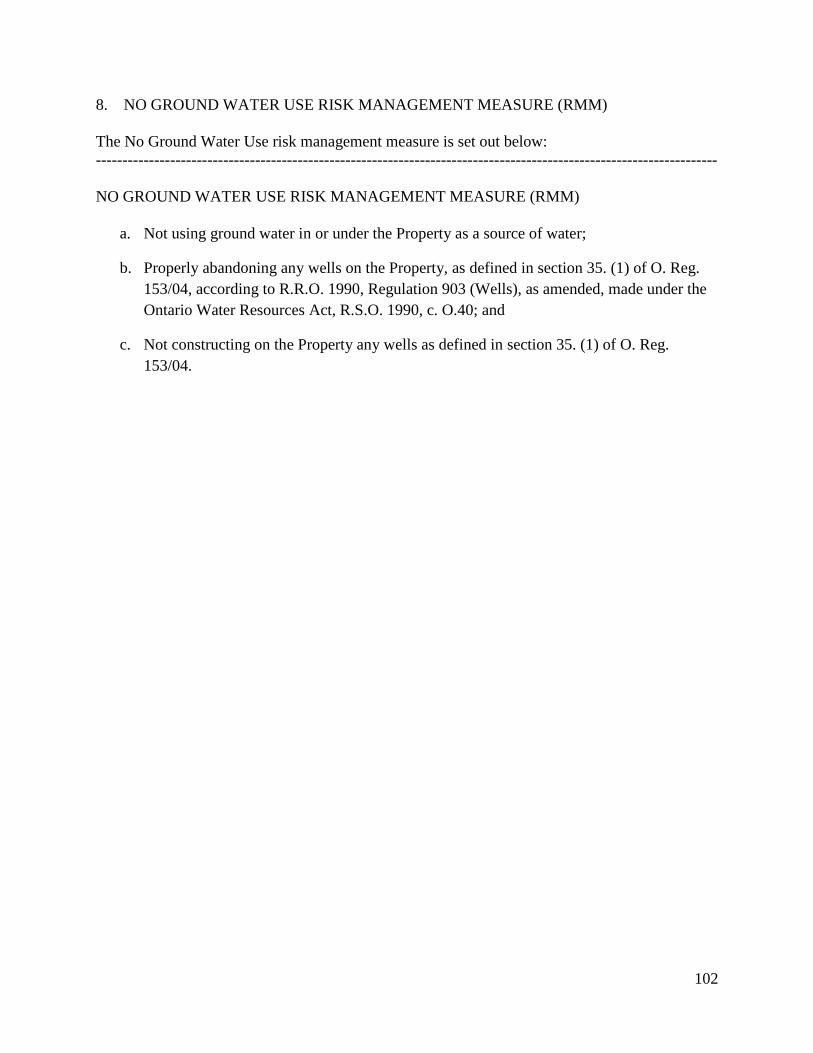
102
8. NO GROUND WATER USE RISK MANAGEMENT MEASURE (RMM)
The No Ground Water Use risk management measure is set out below:
---------------------------------------------------------------------------------------------------------------------
NO GROUND WATER USE RISK MANAGEMENT MEASURE (RMM)
a. Not using ground water in or under the Property as a source of water;
b. Properly abandoning any wells on the Property, as defined in section 35. (1) of O. Reg.
153/04, according to R.R.O. 1990, Regulation 903 (Wells), as amended, made under the
Ontario Water Resources Act, R.S.O. 1990, c. O.40; and
c. Not constructing on the Property any wells as defined in section 35. (1) of O. Reg.
153/04.

103
9. HEALTH AND SAFETY PLAN REQUIREMENT
The Health and Safety Plan requirement is set out below.
---------------------------------------------------------------------------------------------------------------------
HEALTH AND SAFETY PLAN REQUIREMENT
a. In addition to any requirements under the Occupational Health and Safety Act, R.S.O.
1990, c. O.1, preparing and implementing a written health and safety plan for the
Property, prepared by a Competent Person in consultation with a Qualified Person and to
be retained by the Owner, and be available for inspection upon request by a Provincial
Officer, that includes information concerning the potential hazards and safe work
measures and procedures with respect to the Property Specific Contaminants of Concern
at the Property and the communication of this information to all persons who may be
involved in Intrusive Activities at the Property, including, at a minimum:
i. the procedures and timing for implementing the plan, including the supervision of
persons implementing the plan;
ii. all relevant information concerning the presence of, human exposure to, and risk
posed by, the Property Specific Contaminants of Concern through dermal contact,
soil or ground water ingestion and inhalation of soil particles or vapour, and
concerning any biogenic gases such as methane that may be present at the
Property including information in the Risk Assessment,
iii. all relevant information, measures and procedures concerning protection of the
persons from exposure to the Property Specific Contaminants of Concern and the
precautions to be taken when undertaking Intrusive Activities, including the
supervision of workers, occupational hygiene requirements, use of personal
protective equipment, provision of air flow augmentation in excavations or other
areas or situations of minimal air ventilation, and other protective measures and
procedures as appropriate;
iv. all relevant information concerning the presence and significance of the risk
management measures and requirements which are being, or have been,
implemented at the Property,
v. the procedures and timing for implementing emergency response and contingency
measures and procedures, including contact information, in the event of a health
and safety incident; and
vi. the recording, in writing, of the implementation of the plan and any health and
safety incidents that occur, to be retained by the Owner and be available for
inspection upon request by a Provincial Officer;

104
and which is,
vii. delivered to the Owner before any Intrusive Activities are undertaken at the
Property; and
viii. updated and delivered to the Owner within 30 days following making any
alteration to the plan.
105
10. SOIL AND GROUND WATER MANAGEMENT PLAN REQUIREMENT
The Soil and Ground Water Management Plan requirement is set out below.
---------------------------------------------------------------------------------------------------------------------
SOIL AND GROUND WATER MANAGEMENT PLAN REQUIREMENT
a. Preparing and implementing a written soil and ground water management plan for the
Property, prepared by a Qualified Person and to be retained by the Owner, and be
available for inspection upon request by a Provincial Officer, for managing excavated
soil or soil brought to the Property, and, if any, ground water from dewatering during
Intrusive Activities at the Property, so as to prevent exposure to or uncontrolled
movement or discharge of the Property Specific Contaminants of Concern in soil or
ground water at the Property, including, at a minimum:
i. procedures and timing for implementing the plan, including the supervision of
persons implementing the plan;
ii. measures to control dust and prevent tracking of soil by vehicles and persons from
the Property, including the cleaning of equipment and vehicles;
iii. measures, in addition to any applicable measures specified in O. Reg. 153/04, to
manage soil excavated at the Property and any soil brought to or removed from
the Property, including:
(a) characterizing for contaminant quality all excavated soil and any soil
brought to the Property, including determining whether the soil:
1. is Capping Soil;
2. meets the Property Specific Standards; or
3. exceeds the Property Specific Standards;
(b) managing excavated soil separately from any soil brought to the Property,
including any excavated soil that is to be:
1. used as Capping Soil at the Property;
2. otherwise used as fill at the Property;
3. removed from the Property for off-site storage or processing but is
to be returned for use as fill at the Property; or
4. removed from the Property for off-site use as fill or disposal; and

106
(c) stockpiling of excavated soil and any soil brought to the Property in
separate designated areas that:
1. reflect the distinctions described in parts iii. (a) and (b);
2. have been lined and covered, as appropriate, to prevent
uncontrolled movement or discharge of the Property Specific
Contaminants of Concern;
3. have been bermed or fenced, as appropriate, to restrict access by
persons; and
4. have storm water runoff controls in place to minimize storm water
runoff contacting stockpiled soil, with provision for discharge of
storm water runoff to a sanitary sewer or to other approved
treatment if needed;
iv. measures to manage storm water and any ground water from dewatering at the
Property to prevent the movement of entrained soil and Property Specific
Contaminants of Concern within and away from the Property, including, in
addition to any applicable measures specified pursuant to other applicable law or
other instruments, measures such as silt fences, filter socks for catch-basins and
utility covers, and provision for discharge to a sanitary sewer or to other approved
treatment if needed; and
v. recording, in writing, the soil, storm water and any ground water management
measures undertaken, in addition to any applicable record keeping requirements
specified in O. Reg. 153/04 or pursuant to other applicable law or other
instruments, to be retained by the Owner, and be available for inspection upon
request by a Provincial Officer, including:
(a) dates and duration of the Intrusive Activities being undertaken;
(b) weather and site conditions during the Intrusive Activities;
(c) the location and depth of excavation activities, and dewatering activities, if
any;
(d) dust control and soil tracking control measures;
(e) characterization results for excavated soil and any soil brought to or
removed from the Property, and for any ground water from dewatering;

107
(f) soil management activities including soil quantities excavated and brought
to and removed from the Property, and stockpile management and storm
water runoff control;
(g) management activities for any ground water from dewatering;
(h) names and contact information for the Qualified Persons and on-site
contractors involved in the Intrusive Activities;
(i) names and contact information for any haulers and receiving sites for soil
and any ground water removed from the Property, and for haulers and
source sites of any soil brought to the Property; and
(j) any complaints received relating to the Intrusive Activities, including the
soil, storm water and any ground water management activities;
and which is,
vi. delivered to the Owner before any Intrusive Activities are undertaken at the
Property; and
vii. updated and delivered to the Owner within 30 days following making any
alteration to the plan.