mg bjj mg b parts of the engine, showing cylinder head, block and associated parts above, with...
TRANSCRIPT

Supplement to "Mo:or Trader," 30 September 1964
Mo-tor Trader SERVICE DATA NO. 429
MG B Manufacturers: B.M.C. Ltd., Cowley, Oxford.
❖❖❖❖❖❖❖❖❖❖❖❖❖❖❖❖❖❖❖❖❖❖❖❖❖❖❖❖ ❖ ❖❖ All righis reserved. Th is Service Data ❖❖ Sheel is compiled by the lechnical slaff of ❖ ❖ MOTOR TRADER, from iriformatio11 made ❖ 9 / ❖ ❖· available by ihe vehicle manufacturers arH ❖ ❖ from our own experience. It is the copyright ❖ ❖ of 1/tis journal, a11d may not be reproduced, ❖ ❖ h •:• ❖ in whole or in purt. wit out permission. ❖ -;• Tflhile care is taken to ensure accurac,, we ❖ ❖- do not accept responsibility for erro;s or ❖� ❖ (- om,ssions. ❖ ❖❖❖❖❖❖❖❖❖❖❖❖❖❖❖❖❖❖❖❖❖❖❖❖❖❖❖❖
INTRODUCED two years ago, the MG B
was seen to be a logical development of the then cuµent " A " model. From a
construction point of view, the "B" car was brought into line with other B.M.C. _produc�s, and opportunity taken to fit ma,.or un1ts which compare, basically at least, with those used on other models of the range. Ther(: are, of course, detail differen�es in �h� un_its as applied to the MG B, and smce ongmal introduction there have been several changes to specification. Where service procedure is affected, these are mentioned in the text matter of this article.
The car is powered by a 4-cylindered o.h.v. engine of some 1798cc. This,, unit is available in two compression ratid sdltes, and the higher of these is "standard." In basic construction, this engine is similar to the "B "-series units. Transmission of the drive is taken through an hydrauiically operated single dry plate clutch to a four-speed synchromesh gearbox controlled by centre remote type lever. Overdrive is an optional fitment, and when installed, compares in detail with that described in Service Supplement No. 262/CZ0. From the output shaft of the overdrive, or gearbox, the drive is taken via a short universally jointed propellor shaft to the hypoid bevel drive gear contained within the casing of the three-quarter floating rear axle.
Front suspension is of the coil spring and wishbone pattern, damped by hydraulic shock absorbers, and steering is effected through a rack and pinion layout. Suspension at the rear is by semi-elliptic leaf springs, damped by hydraulic piston type shock absorbers.
Identification of vehicles follows customary B.M.C. pattern, and consists of chassis (car) and engine serials. The car number is to be found stamped on a plate which is attached to the top left-hand side of the front bulkhead, and the engine number is to be found stamped on a plate which is secured to the right-hand side of the cylinder block. The engine number itself comprises a series of letters and numbers which present in code the capacity, make and type of the unit fitted, ancillaries fitted, and the type of compression ratio together with the serial number of the unit. Other major units, notably the gearbox, rear axle, etc., are also numbered in serial. It is essential that all these relevant numbers are quoted when corresponding with the vehicle manufacturers, or when ordering spare parts.
Special tools for use in speeding up certain repair operations are available from the manufacturers through their distribmivc network and a list of those considered the more es;ential is included in this article.
Threa<t• and hexagons are, in the main, ot the S.A.E. pattern and form.
DISTINGUISHING FEATURES. This model is easily recognizable from almost any standpoint, due to the revised styling treatment incorp�rating wrap around bumpers _front. and rear, recessed headl_amps at. the front, and flush fitting/tail lamps at rear. The fog lamps depicted tn the tllustrat,on are optional fittings
ENGINE Mounting
At front, mounting rubber blocks are bolted up to frame brackets which are in lllrn bolted up to engine plate flanges. Lower portion of each mounting bracket is bolted to crankcase side direct, and mounting plates are bolted to body side members.
At rear, tailcase of gearbox rests in cradle of mounting cross-member, which is bolted up between chassis frame members. Bonded rubber mounting blocks are bolted up to cradle mounting bracket abmments by one bo!t each, and to gearbox bosses by two bolts each. Additional stay rod bolted up to chassis frame member at one end, and clevis
bolted to gearbox extension at the other. Tighten all bolts and nuts fully. Removal
Engine may be removed with or without gearbox. If gearbox is to be serviced, complete power unit should be removed.
To remove complete unit proceed as follows: drain oil form engine and coolant from radiator, disconnect batteries. Remove bonnet after taking out hinge securing nuts, washers and screws, also stay rod. Detach safety catch and bracket, also bonnet lock cable control. Take out radiator matrix after removal of top and bottom water hoses and, if an oil cooler is not fitted, taking out top radiator/diaphragm screws to release stays,
INSTRUMENTS, CONTROLS, GEAR POSITIONS AND BONNET LOCK 1. Direction indicator switch. 11. Lightin,: switch 20, Panel light switch 2, Hom push 12. Ignition/starter switch 21. En,:ine r.p.m. indicator 3. Map lifbl 13. Choke 22. Fuel rau,:e 4. Map light switch 14. Oil pressure and water tempera- 23. Overdrive switch (optional) 5. Bonnet release lure gaure 24 A I t d 1 6. Ventilator 15. Windscreen washer control · cce era or pe a 7, Heater air control (optional)
16_ Speedometer 25. Brake pedal
a. J!eater temperature control (op-17_ Main-beam wamin• li•ht
26, Clutch pedal t,onal)
. d' • . • r hi t7, Handbrake
9. Blower motor switch 18. L.H. 1_n �cator wam!ng !g ,s. Gear lever . . 10. Windscreen wiper switch 19. R.H. 1nd1cator warning hght 29. Headlamp dip sw,tch Inset upper left; shows method of releasing bonnet safely catch. Below innor !ell: siting of the 1teerin1 column mounted controls and near left operative positions of the centre mounted 1-'' lever.

jj MG B
Parts of the engine, showing cylinder head, block and associated parts above, with crankshaft and other reciprocating parts below
Supp/emem to '' .Motor Trader," JO September 1964

Supplement to "Motor Trader," 30 September 1964
GENERAL DATA Wheelbase Track: front and rear (wire wheels)
front{. disc wheels
rear Turning circ e Ground clearance (min) Tyre size: front} rear Overall length Overall width Overall height (hood raised) Weight (dry)
SPECIAL TOOLS
Crankshaft gear and pully remover Engine front cover locating bush Valve sprinf compressor Oil pump release valve grinding-in Startin( dog nut spanner Camshaft liner remover and replacer Adaptors: front ·
centre rear
Camshaft liner reamer Cullers: front
rear
Reamer pilot: front centre rear
Impulse extractor (UNF) Adaptor GEARBOX Oil seal remover
(adaptor)
�:�:I ���·�·EAR AXLE Front and rear hub extractor
tool
(adaptor bolls ,\ in UNF) Pinion outer race utractor (basic tool) Dill. bearing cage remover (basic tool) (adaptor) Pinion bearin, pre-load gauge Rear axle setting fixture and gauge block Coil spring compressor Wire wheel bush remover
711 7in 411 1!in 4ft 1 in 4ft 1 ¼in
3211 Sin 5.60-14 1211 8!in 4ft 11 11 in 4ft 1 iin
1,920Ib
Part No.
1862 1863 18G 45 18G 69 18G 98 180 124A 18G 124F 18G 124C 18G 124B 18G 123A 18G 123E 18B 123B 18G 123L 18G 122AB 180 123AC 18G 284 18G 284A
18G 389 180 389B 18G 471
18G 304 18G 304B 180 264 18G 47C 18G 47T 18G 207 18G 191A 18G 693 18G 363
NUT TIGHTENING TORQUE DATA
lb. ft ENGINE Main bearing cap nuts 70 Flywheel set screws 40 Small end clamp bolls 25 Bii end bolls 35-40 Cl, inder head nuts 45-50 C utch/flywheel bolls 25-30
REAR AXLE Crown wheel/dill. carrier 55-60 Dill. bearini cap nuts 60-65 Pinion bearrng nut 135-140 Rear hub nuts 180
FRONT SUSPENSION Brake disc/hub 40-45 Brake caliper mounting 40-45 Bearing retaining nut 40-70
then removing screws securing each side of diaphragm to body. If oil cooler is fitted, its pipe connections must be parted before taking out radiator and diaphragm assembly. Disconnect and remove carburettors, together with associated controls and linkages. Disconnect and remove all pipes, wires and controls to engine. Undo exhaust pipe ar manifold flanges, remove heat shield. Take off coil, together with bracket from front engine mounting, remove oil filter and starter motor. Take weight of engine and support gearbox. Drain oil from gearbox, mark propeller shaft flanges for correct replacement, and remove shaft, also undo speedometer drive. Remove clutch slave cylinder from bellhousing and tic up out of way. Take out screws securing rear cross-member to chassis frame, and allow gearbox to rest on fixed body cross-member. Remove stay rod from
7� Diagram showing order of tii:htening cylinder head. See also table of" Nut Tightening Torque Data "
gearbox, and screws securing rear mountings to gearbox. Take out cross-member and stay rod. Remove gearlever from tower and rubber boot from tunnel. Remove screws and nuts securing front mounting brackets to frame brackets, and manoeuvre assembly forward until it is clear of cross-member, tilt assembly and lift out of car. Crankshaft Three main bearings, thin-wall. steelbacked, copper-lead lined shells loc-ated by tabs in bearing caps. End-float controlled by split thrust washers either side of centre main bearing, and lower halves retained by tabs in cap. Fit with oil grooves to crankshaft. No hand fitting permissible. Main bearings may be changed without removal of shaft. Flywheel spigot mounted and flange bolted to crankshaft by six bolts and nuts. Spigot bush, renewable, pressed mw crankshaft end, shrunk-on starter ring gear fitted. Timing sprocket keyed to front end of crankshaft by inner of two Woodruff keys, aligning shim abuts against inner boss of sprocket. Renewable oil seal pressed into timing case cover. Dynamo and water pump drive pulley keyed to crankshaft by outer of two Woodruff keys, retained by starter dog screw. Sump sealing effected by compos;tion gasket around flange, and two square section seals at rear, either :;ide of main bearing cap, which forms lower half of collecting ring around oil return thread on crankshaft. All bolts to be tightened to specified torque figures. Connecting Rods Big ends offset, thin-wall bearings, steel backed, copper-lead liners located by tabs in rod caps. No hand fitting permissible. "H "-section rods split diagonally, for removal through cylinder bores. Assemble rods with locating tabs mating, and oil bleed hole in longer side of rod shoulder away from camshaft. Gudgeon pins are boltclamped in split small ends, clamp bolts fitted towards camshaft. Pistons Aluminium alloy, dished crowns and solid skirt type. Pistons supplied for selective assembly and oversize dimensions are stamped in an ellipse, together with word " FRONT " on piston crowns. When reboring, ensure that oversize dimension of bores is stamped in prominent position on cylinder block face. Top piston ring (compressivn) plain, second and third rings are taper faced and marked "T" (top) for correct assembly. All rings, including scraper ring are litt�d above gudgeon pin. Oversize pistons available for service as in table of "Piston Data." Camshaft Double row roller endless chain dr:ve. Spring-loaded helix and neoprene slipper type tensioner bolted to crankcase. Chain slack is taken up by increase of spring pressure on slipper as helix unwinds. Chain wheel is keyed to front end of shaft and retained by lock tab and nut. Camshaft runs in three white metal-lined, steel-backed bearing shells which are pressl!d d' rect into block. End-float controlled on from bearing. Dot punch marks on both driving and driven wheels indicate correct nming and must be together, engine at TDC No. I cylinder on compression, when chain is fitted. Valves Overhead, non-interchangeable. Inlet larger than exhaust, split cone cotter fixings, retained by spring clips. Rubber sealing rings with retainers on valve st.:m;: below collars Valve guides plain, no shoulder, non-interchangeable, exhaust guides counterbored at bottom and both types countersunk
MG B iii
ENGINE DATA I GENERAL Type 180 and 18GA No. of cylinders 4 Bore x stroke: mm 80,26 X 89
in 3.16 X 3,50 Capacity: c.c. 1,798
cu. in. 109.8 Max. b.h.p. al r.p.m. 95 al 5400 Max. torque lb. ft. at r.p.m. 105 at 110 at Compression ratio
3,000 8 : 1
3,000 8.8 : 1
CRANKSHAFT AND CON. RODS
Main Bearings Crankpins Diameter 2. l26-2.127in 1.8759-1.8764in Length 1.125in .995-1.00Sin Running clearance: main bearings 1-001-.0021i11
big eods .001-.0021in End float: main bearings .002-.003in
big ends .008-.012in Undersizes .020-.040in Con. rod centres 6.50in No. of teeth on starter ring gear/
�inion 120/9
PISTONS AND RINGS
Clearance (skirt) top .0036-.0048in bottom .0018-.0024in
Oversiies .010, .020, .030, .040in
Gudgeon pin: diameter .750in fit in piston .0001-.00035in flt in con. rod .0001-.0006in
Compression Oil Control
No. of rings 3 1 Gap .012-.017in .012-.017in Side clearance in
grooves .0015-.0035in .0016-.0036in Width of rings .0615-.0625in .1552-.1662in
'---- -----
-- -�--------
CAMSHAFT -----
Bear ing journal: diameter(in)
Front I Centre
I-;;;-
-1.788 11.728 1.622 1.789 1.729 1.623 ---.------
Bear End Timi
ing clearance .001-.002in float .003-.�0Jin
.375in ng chain: pitch No. of links 52
------
VALVES -------
diameter diameter
Head Stem Face -angle
g length: •
Sprin ire fill al
ed load
lnl£1
1.562-1.567in .342in 451
0
Inner
1��in 1i',1in 28-321b
Exhaust
1.343-1.348in .341-.342in 45}0
Outer
2,l',in 1 ,-'}:-in 721b
at top. Exhaust guides are larger than inlet guides. When renewing, guides �hould be pressed or driven in from top until they project ½in. from machined surface of valve spring scat. Valve Guides Projected iin. before the following numbers: - 18GA-U-H 11927 18GA-RU- 11150 18GA-RU-L 9710 18GA-U-L 8313 After the above numbers, projected { in. except 18GA-U-H 12001 to 12175 inclusive. Tappets and Rockers Shouldered barrel type tappets sliding direct in crankcase. Access obtained through side openings in crankcase. Bushed rockers, all interchangeable, are mounted on shaft carried in four pillars on cylinder head. Shaft located by grubscrew and lockplate on top of No. 4 (rear) pillar, which is drilled for oil feed through drillings in head and .:ylinrlcr block. Pairs of rockers for each cylinder are positioned each side of each rocker pillar and are located by separating springs between rockers of adjacent cylinders. Pushrods may be removed after tappet adjusting screws have been slacker:cd right off. Inner r-x:kers may then be pulled a;ide

iv MG B
against separating springs. End rcckers must be taken off, after removal of split pin, plain washer and double coil spring washer. Lubrications
Eccentric type pump spigoted in recess at rear of cylinder block and driven by slotted shaft from skew gear at rear end of camshaft. Pump may be removed after taking off sump and pick-up strainer and three seeming nuts. Two pump body bolts must be undone, after removal of assembly from engine, to dismantle pump. Cylindrical gauze intake strainer in sump, flange bolted to suction pipe on pump body, strainer components retained by central set bolt. Normal running pressure between 30 and 8!) lb/sq in, engine hot,
Cooling System Pump and fan, thermostat loca�cd in water
outlet port in cylinder head. Pump spindle has renewable seal and runs in two ball bearing races. Adjust fan belt so that there is lin play either way in vertical rue of belt.
TRANSMISSION Clutch
Hydraulically operated, diaphragm spring type. Unit consists of driven plate, pressure plate, diaphragm spring and cover assembly. Hydraulic system consists of master cylinder coupled to slave cylinder operating releast, mechanism.
No provision for adjustment in service. Flywheel run-out not to exceed .003in., and alignment of thrust pad relative to its face and trunnions should be within .00Sin.
Access to clutch for service after removal of engine or gearbox. Gearbox
Supplement to "Motor Trader," 30 September 1964
lever control, remote control pattern. Pro- second. Remove gearbox front cover, noting pellor shaft sliding joint on mainshaft. shims between cover and front bearing. Un-
To remove gearbox-power unit should be screw retaining setscrew and remove reverse removed as detailed in engine section, after shaft and idler gear. Tap out layshaft, allow-which, gearbox may be paned from engine ing cluster to rest on bottom of box. With-at engine rear mounting plate, great care draw mainshaft assembly to rear, and with-being taken to ensure that no load or stress draw first motion shaft and drive gear from is placed upon clutch release plate drive front. Note 18 spigot needle rollers. Lift out straps. Gearbox, complete with bellhousing layshaft gear cluster and two thrust washers. and rear extension may not be removed To dismantle rear extension remove rear separately, without removal of engine. remote control rod selector arm and key.
To di&mantle mainshaft assembly, remove To Dismantle Gearbox items in following order: 3rd/4th speed baulk
Remove dipstick, drain plug and speedo- ring synchro sleeve and hub; second speed meter drive pinion. With Tool No. 18G 2 baulk ring. If and when synchro sleeve is remove· propellor shaft drive flange. Take removed from its hub, care should be taken off remote control tower, gearbox extension to preserve three locating baUs and springs. side cover, lift out interlock plate and Press down front thrust washer locating peg, bracket. Slacken locating screw on remote rotate splined washer to line up wi-th those control front selector lever, unscrew nuts and on shaft and remove washer. Take off 3rd screws securing extension to gearbox, and speed gear and bush, also thrust washer to take off extension. Preserve remote control release 2nd speed gear, bush and baulk ring. selector lever, which will be freed upon Remove thrust washer from splined shaft withdrawal of extension and withdraw shaft and take off 2nd speed gear and hub. Take and rear selector lever from rear extension. off'. rear retaining nut, washer and speedo Take selector lever off shaft, and withdraw dnve gear and key toge-ther with distance-split bush and circlip from selector. piece, from shaft. Take off bearing and its
Unscrew three countersunk setscrews and housing. Extract one circlip from Jaygear, seven hexagon head setscrews holding gear- push out bearing and distance cube box cover and remove cover. Remove two assemblies (three races, one distance tube). nuts and six setscrews securing extension to
To Assemble Gearbox gearbox, and pull off extension simultan-eously manreuvring remote control shaft To assemble gearbox.-Reverse procedure selector lever down and out from selectors. of dismantling, noting following points:-Cut locking wire and unscrew three change Layshaft: fit circlip to innermost groove in speed fork setscrews. Release three locknuts gear, hold shaft vertically in vice, assemble and slacken fork locating screws. Undo two a roller bearing on shaft against vice jaws and setscrews and remove shifter shaft locating slide gear over shaf,t and bearing with largest block, with shifter shafts. Note dowels in gear downwards. Remove shaft from vice block. If rods are withdrawn from locating and push bearing into gear against circlip. block preserve three selector balls and Fit end roller bearing assembly and circlip. springs. Withdraw forks from box in follow- Slide distance tube into other end of gear ing order: reverse, top, third, first and followed by other end bearing and circlip.
I .. � r @ n r ( ' (@t $i)ffi�- ;�--5 (@)�{Pi@ @�@c{ ====:::::i0©�@1f})(@) I.\
tJ
�,----�--::------,,-,;(".-�"'
Gearbox components, running gear and /oysha(t shown above, with detail of the gearcasing and selector mechanism centre and below
Supplement to "MoNr Trader," 30 September 1964
Mains haft
Press rear bearing into housing, and bearing on to shaft. Fit speedo gear drive to shaft, together with key. Fit 1st/2nd gear synchro assembly to shaft, followed by baulk ring and rear thrust washer. Fit 2nd speed gear bush to shaft, ensure that lugs face forward, and that oil hole in bush lines up with oil hole in shaft. Assemble 2nd speed gear and interlock washer so that the washer engages lugs on bush. Fit 3rd speed gear bush, lugs first; engage lugs with thrust washer and ensure that oil hole and cut-away in bush line up with holes in shaft. Place retaining pin spring and pin in shaft and 3rd speed gear on bush, cone frontwards. Position gear so that hole in cone is in line with retaining peg, depress peg with thin drift, fit thrust washer to shaft, turn washer to allow peg to lock in position. Check end-float of 2nd/3rd speed gear. Thrust washers available in four thicknesses, .OOlin tolerance from .1565-.1615in. Assemble 3rd/4th speed gear rear baulk ring, synchromesh and front baulk ring.
Refit front end cover to gearbox, clutch lever and release fork and fit selectors to shifter shaft rear ends. Both shifter shaft locating block to rear face of gearbox and insert shifter shafts. Inse11t selector forks; reverse, first and second, third and top in gearbox. Push shifter shafts into box and through forks; insert, tighten and wire up setscrews. Position selectors on rear end of shifter shafts, tighten and wire up setscrews. Assemble rear extension of gearbox locating control rod selector arm in shifter rod selectors. Fit interlock arm to rear extension and refit cover.
Propellor Shaft Hardy Spicer needle roller bearing uni
versal joints. Sliding joint behind front drive flange. Nipples provided for lubrication of joints.
Rear Axle B.M.C. "B "-type three-quarter floating,
hypoid bevel final drive. Rear cover welded to banjo-housing. Apar,t from attention to hubs and half-shafts, axle cannot be serviced without full range of tools. Replacement axles are available as units and should be used when possible. Axle components may be withdrawn wit'hout removing axle from vehicle.
Half-shafts (interchangeable) upset at outer ends ·to form flanges which register on wheel studs on hub flanges. Hubs for wire wheels fitted to splined half-shafts and retained by hub studs. Hubs run on ball bearings retained on axle tube ends by nuts with tabwashers. Lipped oil seal in hub behind bearing (lip to bearing), and spacer washer is fitted on outer side of bearing. If shaft is withdrawn, note paper gasket behind flange.
Bevel pinion shaft runs in tape-roller bearings. Outer races pressed into final drive housing. Distance-piece between inner races, which are nipped up by driving flange nut. Shims between distance-piece and front bearing (.004-.012in available) regulate preload on bearings, which should give 13-lSlb in. drag with oil seal fitted. No adjustment for pinion mesh without special tools and graded distance-pieces.
Crown wheel spigoted on one-piece differential cage and retained by six setscrews. Differential side bevel gears run directly in cage, planet pinions have spherical washers.
Differential assembly carried in semithrust ball bearings in split housings. Thrust side of bearings must face outwards. Shims between differential cage and inner races of bearings for mesh adjustment. Adjust so that the crown wheel is just free, without play, and backlash is as etched on crown wheel (usually .005-.0llin.), then add shims to offside bearing to give .002in. total preload. Differential assembly should then be light push fit in housing. Backlash must be not less than .00Sin.
To remove axle from car, proceed as follows: Raise rear of car, mark propellor shaft universal joints for correct replacement, undo coupling flanges and remove shaft. Remove check straps. Take out split pins and clevis pin securing brake cables to each operating lever. Remove small nut and Phillips recessed-head screw securing handbrake cable to axle casing. Remove brake balance lever from pivot on casing. Disconnect brake fluid pipe line at union, release flex pipe from battery box support bracket. Release exhaust pipe from manifold junction and support brackets, lower pipe assembly. Take out nut and spring washer from front anchor pin. Support axle casing, remove rear shackle plates, brackets and rubbers. Lower axle support until axle rests on road wheels. Remove front anchor pins, and roll axle from beneath car.
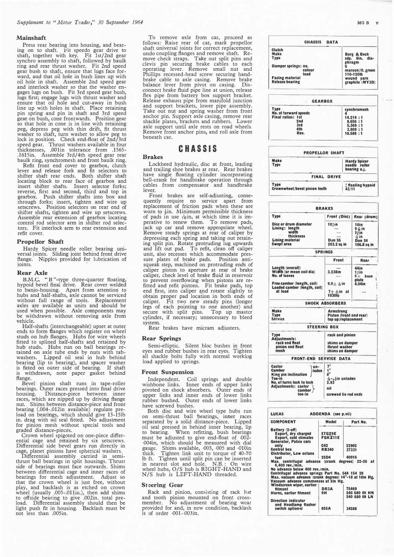
CHASSIS Brakes
Lockheed hydraulic, disc at front, leading and trailing shoe brakes at rear. Rear brakes have single floatini cylinder incorporating bell-crank for handbrake operation through cables from compensator and handbrake lever.
Front brakes are self-adjusting, consequently require no service apart from replacement of friction pads when these are worn to ¼in. Minimum permissible thickness of pads in use n-in, at which time it is imperative to renew them. To remove pads, jack up car and remove appropriate wheel. Remove steady springs at rear of caliper by depressing each spring and taking out retaining split pin. Rotate protruding Jug upwards and lift out pad. To refit, clean off calipf'r unit, also recesses which accommodate pressure plates of brake pads. Position antisqueak step, machined on protruding ends of caliper piston to aperture at rear of brake caliper, check level of brake fluid in reservoir to prevent overflowing- when pistons are refitted and refit pistons. Fit brake pads, top end first, into caliper :i_nd rotate slightly to obtain proper pad location in both ends of caliper. Fit two new steady pins (longer legs of each pointing to one another) and secure with split pins. Top up master cylinder, if necessary; unnecessary to bleed system.
Rear brakes have micram adjusters.
Rear Springs
Semi-elliptic. Silent bloc bushes in front eyes and rubber bushes in rear eyes. Tighten all shackle bolts fully with normal working load applied to springs.
Front Suspension
Independent. Coil springs and double wishbone links. Inner ends of upper links pivot-ed on shock absorbers. Outer ends of upper links and inner ends of lower links rubber bushed. Outer ends of lower links have screwed bushes.
Both disc and wire wheel type hubs run on semi-thrust ball bearings, inner races separated by a solid distance-piece. Lipped oil seal pressed in behind inner bearing, lip to bearing. When refitting, bush bearings must be adjusted to give end-float of •002-·004in, which should be measured with dial gauge. Shims available, ·003, ·005 and •0IOin thick. Tighten link unit to torque of 40-70 lb ft. Tighten until split pin can be insertedin nearest slot and hole. N.B. : On wire wheel hubs, O/S hub is RIGHT-HAND and N/S hub is LEFT-HAND threaded.
Steering Gear
Rack and pinion, cons1stmg of rack lnr and tooth pinion mounted on front crossmember. No adjustment of bearing wear provided for and, in new condition, backlash is of order ·001--003in.
MGB V
CHASSIS DATA
Clutch Make Borg &Beck Type sdp. Sin. dia-
Damper springs: no. phragm 6
colour maroon/It. r;rHn load
Facinc material 110-120Ib
Release bearing wound yarn graphite iMY3D)
Type No. of forward speeds Final ratios: 1st
2nd 3rd 4th Rev.
GEARBOX
synchromesh 4 14.214 : 1
8.656 : 1 5.369 : 1 3.909 : 1
18.588 : 1
PROPELLOR SHAFT
Make I
Hardy Spicer Type needle roller
bearing u.J.
FINAL DRIVE
Type I
¾ ftoating hypoid Crownwheel/bevel pinion teeth 43/11
BRAKES
Type Front (Disc) Rear (drum)
Disc or drum diameter 101in 10in Lining: len(lh - 9,'fin
width - 1�,n thickness - ,\in
Lininr; material Swept area
Don 55 Don 24 203.2 sq in 106,S sq in
SPRINGS
Front Rear
Lenr.h (overall) - 44in Wid h (or mean coil dia) 3,238in 1Jin No. nf leaves - s+ ba11
FrH camber (len(lh, coil) 9.9± ,';-in plate 4.04in
Loaded camber (len(lh, coil) at load 7± ,\,in at
1030Ib -
SHOCK ABSORBERS
Make [ Armstrong Type
I Piston (front nnd rear)
Service top up/replacement
STEERING BOX
Type Adjustments:
rack and pinion
rack end ftoat shims on damper pinion end float thrust washer mesh shims on damper
FRONT-END SERVICE
Castor }
un-Camber laden King pin inclination
7" 10 80
DATA
T0t-in ¼-,�in unladen No. of turns lock to lock 2.93 Adjustments: castor } camber nil
toe-in screwed lie rod ends
LUCAS ADDENDA (see p,vii)
COMPONENT Model
Battery (2-off) Export, dry charred STGZ9E Export, cold climates FGKZ11 E
Generator, Police cars
Part No.
only C42 22902 Control box RB340 37331 Distributor, Low octane
fuel 25D4 40916 Max. centrifugal advance (crank decrees) 22-26 at
4,400 rev./m1n. No advance below 400 rev./min. Centrifur;al advance sprinr;s Part No. 544 154 28 Max. vacuum advance (crank degrees) 14°-18 at 18in Hr;. Vacuum advance commences at 2in Hr;. Windscreen wiper, earlier
fltment DR3A 75469 Horns, earlier fitment 9H 540 680 08 HN
540 680 09 LN Direction indicator
and Headlamp flasher switch option�I 85SA 34588
I
I
:
y

Y MG B Supplement to "Motor Trader," 30 September /964
From top to bJttom, parts of the steering mechanism complete with column and universal jointing; the front suspension with <Jetai/ of component parts and the rear axle unit

Supplement to "Motor Trader," 30 September 1964 MG B vii
GENERATOR tGNITION WARNING LIGHT
CONTROL eo, :
NG
NY
·1-
2·6 VOLT BATTEAl[S
STAFITCA SOLEt.010 START(A
L.H, FOG 0A DRIVING LAMP
+----h---------.,,10-, RH. FOG OR DRIVING LAMP
� '
A.AOIO I u:..C
·1�----c:}----0,.0.- --
HOAN
HOflN
HORN PUSII
·11•-:i-c----'"""'----=--'""'-�
CIGAA LIGHTEA
L ___ --- - - --- - - - - -s---rJ.Nvvc-- ---f 1•
CtGAA LIGHTER ILLUMINATION
PANEL LIGHT
RW ,, PA/..[L LICHT
RW I•
' '
GP Lll STOP LAM?
SCA[[NWIP(A MOTOA & SWITCH
rt.ASHER
LC.N LGN
L H fAONT FLASHER
IC.ti1Tt011 DISTRIBUTOR
HG we
I•
cooc�
{5"'1 (CB)
flASH(.R ANO HEADLAMP ruci<.
SWITCH
•vtL PIJl,W
CA■LI COLOUII
(001
_c � l lLAfl
W Wi'OTI
T TU.LOW
All f�OtlT fLAS►t[A
II--�"<'--"--=,...;G::.:•'-,=
-c"-'•�-=--;;c�•- c.-.:c,:w:._<n--c�S':'---<�c"w'-=----"-..,.X,:>---i I· 'Lt+ AEAFI FLASH(R r ____ _!l_-0 �-------1 Rtl A[A(l l"L•Srt(A
•I G GA
: ·d----o <'�I· : •11--- __ .J.o. ___ --- - -- --0/9
MAIN BEAM WARNING LIGHT LIGfHIN G SWltCII
l.11,' I PAtl[L ucur ------ __ N --- ------- _J
cGe;W:....,,,,___r.;,., -a",;----,J•
_______ uw ________________ _ _________ ...J
• ))-
---<
Y'co--
"-'uw'--,
�HH[AOLAMP MA!N B[AM
•I • uw
Ui-H[A0LAMP MAIN BE.AM
•I • ""'
AH, HEADLAMP DIP BEAM
UR
LH �[AOUMP DIP BE.AM
UR
RH SIOELAMP
UR
'
: '
uw
PA','fl ,w �,. LIGHT
PANEL LIGHT Rl-,[OSTAT
.... -i:;-.J
,w �,. Ml'.P LIGHT MAP LIGHT
SWITCH
/�I• N'JM8EA PLATE !LL\JMIN,HION
,-c,----''----<>� I R NUMBER PLATE ILLVMINA.TlON
RH Voll. LAMP
I
ol)----<Y'c>----"---,=-""7"""-�-- L----"-------''7,-
-�----<>-"<�-j I,
U·t. SIOELAMP ' '
L H. TAtL LAMP
Model SG9E
I R I I I
�- ______________ uw ____________________ J
LUCAS EQUIPMENT *BATTERY (2-ofl) -
Firing order
LH.fLASH[A WA ANING LIGHT
LGP LCU LGlJ
LGP L GP
F"U(L GAUGE & TANI< UNIT
�:::::::7� I• HEATER SWITCH HFATER MOTOR
�----/� -�tl ___ ◊-� I •
LGY
Wiring diagram by permission of Joseph Lucas Ltd
-
TUNE-UP DATA
1-3-4-2 Model C40
Carlluretlor: make Tappet clearance• (cold): inlet .015in type
Model RB340 exhaust .015in Settings: choke
16° BTDC
LGY
----- ------OPTIONAL EXT-"AS
SNAP ---<=-- CONNECTOR$
[AATH CONNCCTIONS ----�l•MADE VIA CAIILE
o•
-----;1•VI� flXINC BOLTS
&.U, H.8.4 (twin)
*GENERATOR
lcoNTR&�rt
B�� 22700
I Part No. 37334 S'i'ARTING MOTOR
Valve timing: !•let or.:;ns mlet coses exhaust opens
�J��in main Jet 56° ABDC needles: standard No, 5 51° BBDC Model M418G I Part No. 25555
Dri•e 's-type ' Inboard *DISTRIBUTOR High Octane Fuel
Model 25D4 ) Part No. 40897 Max. centrifugal ad•ance (crank degrees) 18-22 at
3000 rev/min. No ad,ance below 400 r.p.m. Centrifugal ad,ance springs. Part No. 54415428 Max. vacuum adnnce (crank degrees) 18-22 at 20,n Hg. No adnnce below 2¼ in. Hg.
IGNITION COIL Model HA12 I Part No. 45102 Primary resislance 3.0-3.5 ohms Running current at 2,000 r.p.m. 1.4 amp.
*WINDSCREEN WIPER Model DR3A I Part No. 75442
Model 9H •HORN(S)
I Part No(s) 54068024H N
54068025 LN Type: Windtone Current consumptioFCAt�·UmJ'Nit" horn)
Model FLS I Fus/��1�
o. 35020
Model 54038033 Fuse ratings 35 amp 50 amp •see also Addenda p, v
SWITCHES Model Part No Ignition/starter 47SA 31973 starter solenoid 2ST 76464 LiChting 57SA 31837 Foglamp 65SA 31828 Long range driving lamp 65SA 31828 *Direction indicator 85SA 34518 Dip 21SA 31800 Stop liF,ht HL2 31802 Panel ,ghl 3R 78405 Wiper 57SA 34426 Steerinf column control CC5 33590
TRANSMISSION UNllS Model Part No.
LAYCOCK Control switch 65SA 31828 Transmission gear solenoid 11S 76522 Vacuum switch 60SA 34508
exhaust closes Standard ignition timing: H.C.
L.C. Location of timing mark
Plugs: make type size
gap
Lamps
*Head RHO dip left
Fog (optional) Long range drivinc (optional) Side/flasher
Stop tail &
Rear and flasher Number plate Panel bulbholder only
{Bulbholder
Map &r::: Gasket
lcnition warning bulbholder only Main beam warning bulbholder only Flasher warning bulbholder only
•see also Addenda.
ADDENDA
Lamps
Head LHD, dip right Head, Export Europe Head, Export France Head, Export Sweden Head, Export U.S.A. and Canada Side and flasher, Export N. America
Stop/tail and flasher, Export N. America
rich No. 6 21° ATDC weak 21 10° BTDC Piston spring colour red 8° BTDC Air cleaner: make Cooper c/shait pulley type paper element and poinltr Fuel pump: make 8.U. Champion type electric H.P. N•9Y min.flow 7 call/hr. 14mm (fin reach) *Set to .021in. for timinc. .024-.026in
Model Part No. BULB OR SEALED BEAM UNIT
Lucas No. Wallace Cap F700 58683 54521872 60/45 8BU WFT576 55189 323 48 BPF WLR576 55188 185 48 BPF 677 52551
{989 side 6 MCC
}382 flasher 21 sec 676 53915 380 stop/tail 6i21 SBC 382 flasher JI sec
54108 534 207 6 sec - 554734 987 2.2 MES - 554734 987 2,2 MES - 574825 - -- 573915 - - -- 573916 - - -- 319408 987 2.2 MES - 54944812 987 2,2 MES - 863511 987 2.2 MES
BULB OR SEALED BEAM UNIT Model Part No. Lucas No. Wattare Cap FT00 58687 415 50/40 Unified European FT00 58685 410 45/40 Unified European FT00 58686 411 45/40 Unified European F700 58688 410 45/40 Unified European FTOO 58684 -677 52552
{989 side 6 MCC
} 53916 382 flasher 21 sec 676 380 stop/tail 6/21 SBC 382 flasher 21 sec I

viii MG B
3
3
24 25
12 11 10 20
KEY TO MAINTENANCE DIAGRAM
DAILY 1. Radiator l check and top up 2. Engine sump J
WEEKLY 3. Tyre pressures-check
*4. Batteries-check and tap up
EVERY 3,000 MILES 5. -carburettor piston dampers } check and
*6. Brake and clutch fluid reservoirs top up 7. Handbrake cable
9. Propellor shaft sliding joint
8. Propellor shaft front and rear
}
universal joints
10. Front suspension & swivel pin :Jrense gun top bush
11, Front suspension swivel pin lower bueh
12. Front suspension swivel pin base 13. Carburettor air filters (dry type)-clean
EVERY 6,000 MILES 14. Engine sump-drain and refill 15. Engine oil filter element-renew 16. Gearbox/overdrive }check and top up 17. Rear axle
* 18. Engine val\'e rocker clearances-check and reset as necessary
RE.COMMENDED LUBRICANTS
CASTROL ESSO
15
Engine: All ttm�eralures Castro1ii.e• Extra Motor Oil above 0°F (-18°C), and Gearflox
Steering rack and Rear Axle (a)
Caslrol Hypoy Gear Oil Gr 90
Water pump and Grease points
Castrolease LM Mulli-purpose Grease H
Oil can, SU carb dashpots. Caslrolile• Extra Motor Oil
Upper cylinder lubricanl Castrollo Upper Cylinder Lubricant
Supplement io "Motor Trader," 30 September 1964
19 5 16 9
B
19. Distributor-check contacts setting, oil auto. advance mechanism, shaft bearing and contact breaker pivot, smear cam with grease
20. Dynamo-two drops engine oil to end bearing, check belt tension
*21. Sparking plugs-clean *22. Disc brake pads-examine for wear, replace if
necessary *23. Front wheel alignment-chec�<
EVERY 12,000 MILES (AS FOR 6,00) MILES PLUS FOLLOWING)
24. Water pum-lubricate sparingly with grease
7 3 17
=-\ 3
·-
FILL-UP DATA
Pints Lilres
Engine sump 7½ 4.26 Oil cooler (when fitted) ¾ .42 Gearbox 4I 2.56 Gearbox wilh overdrive 5 2.84 Rear axle 2} 1.28 Cooling syslem 9¼ 5.4 Cooling syslem wilh heater 10 5.7 Fuel tank 10 galls. 45.4 Tyre pressures:
•ironl and rear 181b/sq in 1.27kg/cm• tfront and rear 241b/sq in 1.69kg/cm 2
25. Steering rack-apply oil gun to nipple and give no more than 10 strokes •standard tyres, normal motoring including sustained
speeds up to 90 m.p.h. 26. Carburettor air clean:rs (dry type)-renew •-Noe shown on diagram tMaximum at speeds in excess ol 90 m.p.h.
B.P.
Energol Visco-Static
Energol SAE 90EP
Energrease L2
- Energol Visco-Static
Energol UCL
DRAINING POINTS
left: shows radiator matrix drain tap access from beneath. Right: cylinder block drain tap situated adjacent to the distributor unit
DUCKHAMS MOBIL SHELL
QSSOO Mobiloil x-100 Special Mulligrade
10W/30.
Hypoid 90 Mobilube GX 90 Spirax 90 EP
L.B. 1 O Groase �·
Mobilgrease M P Retinnx A
Q5500 Mobiloil Special x-100 Mulligrade 10W/30
Adcoid Li�uio U�pcrlube Upper Cylinder Lubricant
FILTRATE STERNOL
10W/30 Mulli�rade
Multiplic
Hypoid Ambroleum EP 90 Gear 90
Super Lithium Grease
Ambroline LHT
10W/30 Mulligrade
Multiplic
Pelroyle Magikoyl
(a) Rearaxleandsteerinc: Fortemperalurebelow 10°F use SAE 80 Hypoid lubricant. Hydraulic brakes and rlutch: Lockhee11 disc brake fluid (Series II) Shock absorbers: Armslrong Super (thin) Shock Absorber Fluid.
Nole: MULTIGRADE OILS. •For temperatures below 10°F (-12°C) use SAE 10W/30 oil .. Approval is also given to Duckhams Q.20-50, B.P. Visco-Stalic "Longlifa" oils and to Monograde or single viscosity oils supplied by the companies listed in this chart.
!'rinied in E,igJand by Cort11L'all Press Lid., Paris Garden, iondon-:-S:E.L
•