mf-7524 instruction manual - juki · to the instruction manual for motor. lower pulley 2) install...
TRANSCRIPT
1
INSTRUCTION MANUALMF-7524
i
CONTENTSⅠ . SPECIFICATIONS ..........................................................................................................1Ⅱ . CONFIGURATION OF THE MACHINE COMPONENTS ...............................................2Ⅲ . INSTALLATION ....................................................................................................................... 3
1. Installing the machine head onto the table ........................................................................................3 2. Selecting the motor pulley and the belt .............................................................................................5 3. Installing the motor ..............................................................................................................................5 4. Setting the belt .....................................................................................................................................6 5. Installing the belt cover .......................................................................................................................6 6. Installing the chain ...............................................................................................................................6 7. Installing the thread guide ...................................................................................................................7 8. Installing the needle bar thread take-up cover ..................................................................................7
Ⅳ . LUBRICATION AND OILING .........................................................................................8 1. Lubricating oil .......................................................................................................................................8 2. Oiling .....................................................................................................................................................8 3. Silicon oil lubricating unit ...................................................................................................................9
Ⅴ . OPERATION .................................................................................................................10 1. Needle ..................................................................................................................................................10 2. Attaching the needle ..........................................................................................................................10 3. Threading the machine head ............................................................................................................. 11 4. Adjusting the stitch length ................................................................................................................12 5. Adjusting the differential feed ratio ..................................................................................................13 6. Adjusting the presser foot pressure .........................................................................................................13 7. Adjusting the thread tension .............................................................................................................14
Ⅵ . ADJUSTING THE SEWING MACHINE .......................................................................15 1. Adjusting the silicon container thread guide ..................................................................................15 2. Adjusting the rocking thread take-up ...............................................................................................16 3. Adjusting the rocking thread take-up thread receiver ....................................................................17 4. Adjusting the rocking thread take-up thread receiver ....................................................................18 5. Adjusting the looper thread cam ......................................................................................................18 6. Adjusting the looper thread cam eyelet ...........................................................................................19 7. Adjusting the looper ...........................................................................................................................20 8. Adjusting the height of the needle ....................................................................................................21 9. Adjusting the rear needle guard .......................................................................................................2210. Relation between the rocking thread take-up timing and the needle thread loop ....................... 2311. Adjusting the height of the feed dog ................................................................................................2412. Installing position of the spreader ....................................................................................................2513. Adjusting the spreader thread guide and the needle clamp thread guide .................................... 2614. Adjusting the front needle guard ......................................................................................................2615. Adjusting the presser foot lift .............................................................................................................2716. Adjusting the micro-lifter ...................................................................................................................2717. Adjusting the feed locus ....................................................................................................................2818. Adjustment of the feed dog in longitudinal direction .....................................................................30
Ⅶ . MAINTENANCE ....................................................................................................................31 1. Cleaning the sewing machine ...........................................................................................................31 2. Replacing the lubricating oil .............................................................................................................31 3. Inspecing and replacing the oil filter ................................................................................................32
– 1 –
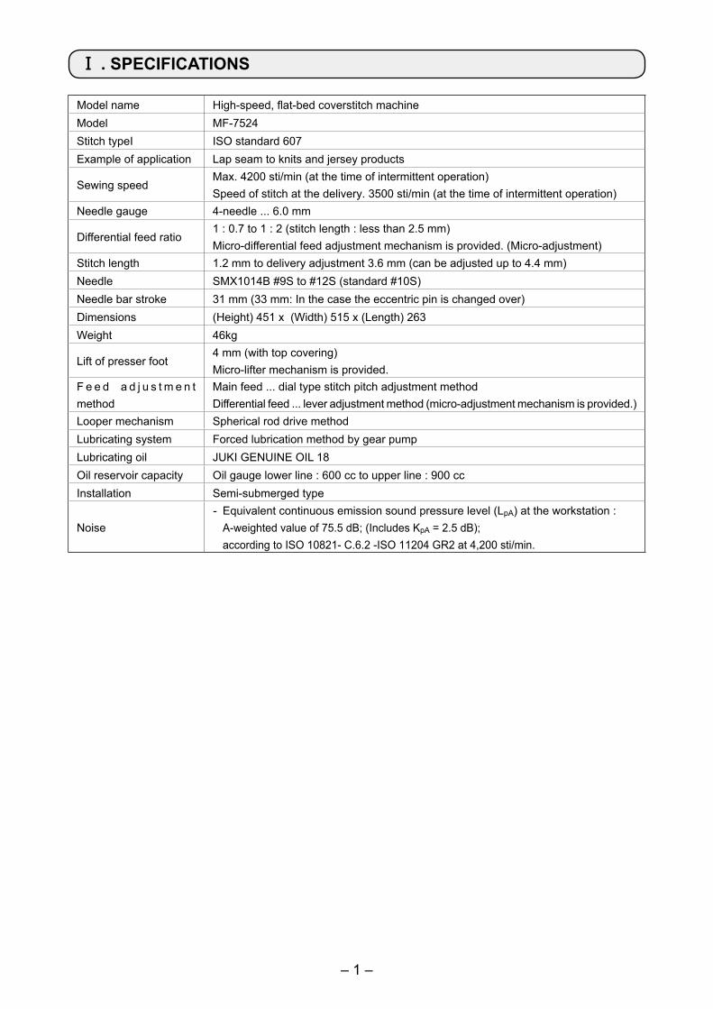
Model name High-speed, flat-bed coverstitch machineModel MF-7524Stitch typeI ISO standard 607Example of application Lap seam to knits and jersey products
Sewing speedMax. 4200 sti/min (at the time of intermittent operation)Speed of stitch at the delivery. 3500 sti/min (at the time of intermittent operation)
Needle gauge 4-needle ... 6.0 mm
Differential feed ratio1 : 0.7 to 1 : 2 (stitch length : less than 2.5 mm)Micro-differential feed adjustment mechanism is provided. (Micro-adjustment)
Stitch length 1.2 mm to delivery adjustment 3.6 mm (can be adjusted up to 4.4 mm)Needle SMX1014B #9S to #12S (standard #10S)Needle bar stroke 31 mm (33 mm: In the case the eccentric pin is changed over)Dimensions (Height) 451 x (Width) 515 x (Length) 263Weight 46kg
Lift of presser foot4 mm (with top covering)Micro-lifter mechanism is provided.
F e e d a d j u s t m e n t method
Main feed ... dial type stitch pitch adjustment methodDifferential feed ... lever adjustment method (micro-adjustment mechanism is provided.)
Looper mechanism Spherical rod drive methodLubricating system Forced lubrication method by gear pumpLubricating oil JUKI GENUINE OIL 18Oil reservoir capacity Oil gauge lower line : 600 cc to upper line : 900 ccInstallation Semi-submerged type
Noise- Equivalent continuous emission sound pressure level (LpA) at the workstation : A-weighted value of 75.5 dB; (Includes KpA = 2.5 dB);
according to ISO 10821- C.6.2 -ISO 11204 GR2 at 4,200 sti/min.
Ⅰ . SPECIFICATIONS
– 2 –
Ⅱ . CONFIGURATION OF THE MACHINE COMPONENTS
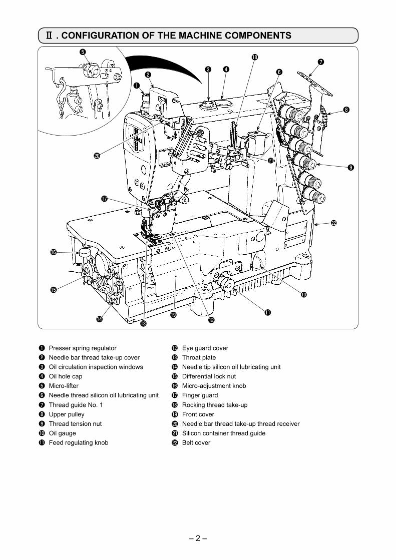
❶ Presser spring regulator � Eye guard cover❷ Needle bar thread take-up cover � Throat plate❸ Oil circulation inspection windows � Needle tip silicon oil lubricating unit❹ Oil hole cap � Differential lock nut❺ Micro-lifter � Micro-adjustment knob❻ Needle thread silicon oil lubricating unit � Finger guard ❼ Thread guide No. 1 � Rocking thread take-up❽ Upper pulley � Front cover❾ Thread tension nut � Needle bar thread take-up thread receiver� Oil gauge � Silicon container thread guide� Feed regulating knob � Belt cover
❶❷
❸ ❹
❺
❻❼
❽
❾
�
���
�
�
�
�
��
�
�
�

– 3 –
[For the V-belt type]Attach the supporting board and the rubber seats as shown in the illustration and properly install the sewing machine.
❶ Bolt ❷ Spacer ❸ Washer❹ Spring washer❺ Nut ❻ Supporting board❼ Spring pin❽ Rubber cushion (Black) × 3❾ Rubber cushion (Gray) × 1
1. Installing the machine head onto the table
Semi-submerged type
WARNING :Do not insert the power plug of the motor into the receptacle until all works have been completed. There is a danger of injury by being caught in the machine.
WARNING :The weight of the sewing machine is more than 46 kg. Be sure to perform the work with two persons or more in case of unpacking, transportation or installation.
Ⅲ . INSTALLATION
❶
❷
❸❹
❺❻
❼❽
❾
❶
A
❷❷
■ Installing the rubber cushion
Part No. Part name Q'ty
❶ 40072505Dust-proof rubber
(Gray)1
❷ 13155403Dust-proof rubber
(Black)3
Install the gray dust-proof rubber to section A only.[For the V-belt type]
– 4 –
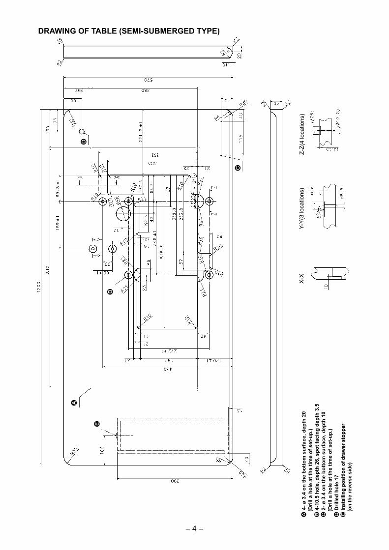
DRAWING OF TABLE (SEMI-SUBMERGED TYPE)
A 4
- ø 3
.4 o
n th
e bo
ttom
sur
face
, dep
th 2
0
(Dril
l a h
ole
at th
e tim
e of
set
-up.
)B
4-1
0.5
hole
, dep
th 2
6, s
pot f
acin
g de
pth
3.5
C 2
- ø 3
.4 o
n th
e bo
ttom
sur
face
, dep
th 1
0
(Dril
l a h
ole
at th
e tim
e of
set
-up.
) D
Dril
led
hole
17
E In
stal
ling
posi
tion
of d
raw
er s
topp
er
(on
the
reve
rse
side
)
Z-Z(
4 lo
catio
ns)
Y-Y
(3 lo
catio
ns)
X-X
A
B
C
D
E
– 5 –
Use a motor pulley which is adaptable to this sewing machine. The sewing speed exceeds the max. sewing speed of this sewing machine and machine trouble will be caused unless a motor pulley which is adaptable to this sewing machine is used.
When you use a new sewing machine, use the machine at a speed of 3,200 sti/min or less for the first 200 hours (approximately one month). A good result can be obtained in terms of the durability.
Motor pulley and belt
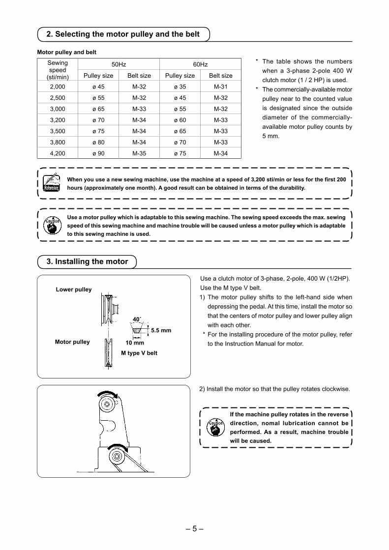
Motor pulley
40˚
5.5 mm
10 mm
M type V belt
Use a clutch motor of 3-phase, 2-pole, 400 W (1/2HP).Use the M type V belt.1) The motor pulley shifts to the left-hand side when
depressing the pedal. At this time, install the motor so that the centers of motor pulley and lower pulley align with each other.
* For the installing procedure of the motor pulley, refer to the Instruction Manual for motor.
Lower pulley
2) Install the motor so that the pulley rotates clockwise.
If the machine pulley rotates in the reverse direction, nomal lubrication cannot be performed. As a result, machine trouble will be caused.
* The table shows the numbers when a 3-phase 2-pole 400 W clutch motor (1 / 2 HP) is used.
* The commercially-available motor pulley near to the counted value is designated since the outside diameter of the commercially-available motor pulley counts by 5 mm.
Sewingspeed
(sti/min)
50Hz 60Hz
Pulley size Belt size Pulley size Belt size
2,000 ø 45 M-32 ø 35 M-31
2,500 ø 55 M-32 ø 45 M-32
3,000 ø 65 M-33 ø 55 M-32
3,200 ø 70 M-34 ø 60 M-33
3,500 ø 75 M-34 ø 65 M-33
3,800 ø 80 M-34 ø 70 M-33
4,200 ø 90 M-35 ø 75 M-34
2. Selecting the motor pulley and the belt
3. Installing the motor
– 6 –
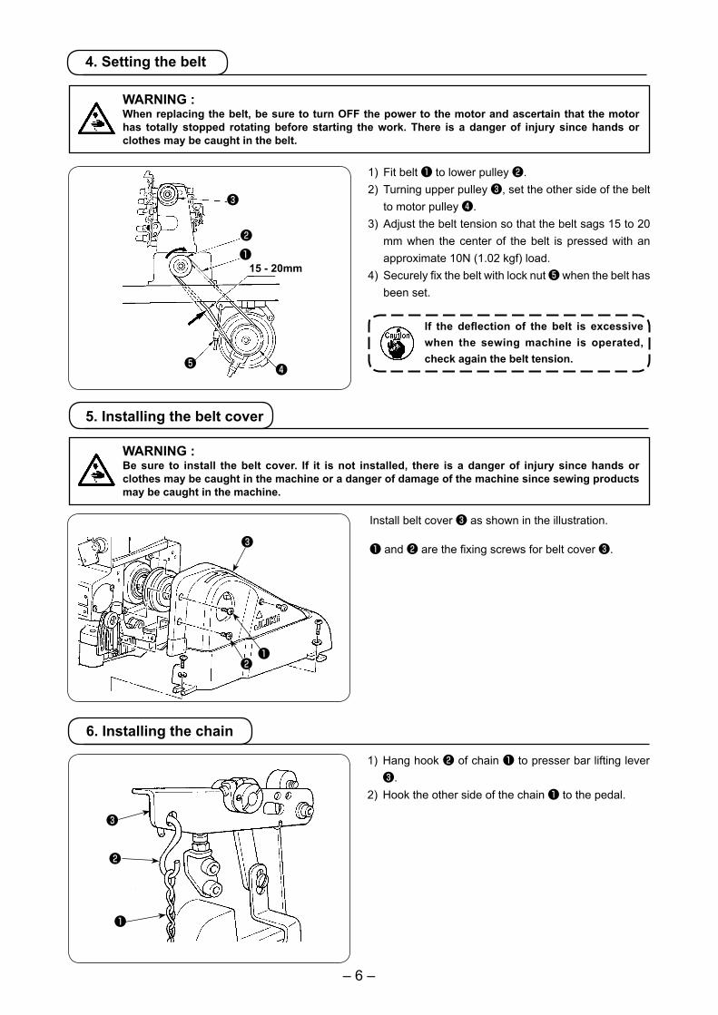
1) Fit belt ❶ to lower pulley ❷.2) Turning upper pulley ❸, set the other side of the belt
to motor pulley ❹.3) Adjust the belt tension so that the belt sags 15 to 20
mm when the center of the belt is pressed with an approximate 10N (1.02 kgf) load.
4) Securely fix the belt with lock nut ❺ when the belt has been set.
If the deflection of the belt is excessive when the sewing machine is operated, check again the belt tension.
❶
❸
❹❺
❷
15 - 20mm
WARNING :When replacing the belt, be sure to turn OFF the power to the motor and ascertain that the motor has totally stopped rotating before starting the work. There is a danger of injury since hands or clothes may be caught in the belt.
5. Installing the belt cover
WARNING :Be sure to install the belt cover. If it is not installed, there is a danger of injury since hands or clothes may be caught in the machine or a danger of damage of the machine since sewing products may be caught in the machine.
4. Setting the belt
Install belt cover ❸ as shown in the illustration.
❶ and ❷ are the fixing screws for belt cover ❸.
1) Hang hook ❷ of chain ❶ to presser bar lifting lever ❸.
2) Hook the other side of the chain ❶ to the pedal.
❸
❷
❶
6. Installing the chain
❶❷
❸
– 7 –
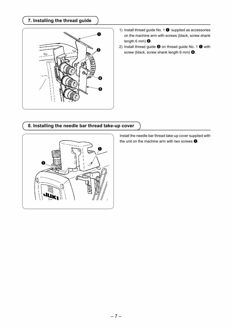
1) Install thread guide No. 1 ❶ supplied as accessories on the machine arm with screws (black, screw shank length 6 mm) ❷.
2) Install thread guide ❸ on thread guide No. 1 ❶ with screw (black, screw shank length 6 mm) ❹.
7. Installing the thread guide
❶
❷
❹
❸
8. Installing the needle bar thread take-up cover
❶
❶
Install the needle bar thread take-up cover supplied with the unit on the machine arm with two screws ❶.

– 8 –
<When using the sewing machine for the first time>Lubricating oil has been taken out at the time of delivery. Be sure to supply lubricating oil before using the sewing machine for the first time.• Oil used : JUKI GENUINE OIL 18
Do not use oil addition agent since deterio-ration of lubricating oil or machine trouble will be caused.
To add oil, remove first the oil inlet cap ❷ indicated as "OIL". Then, add oil from the oil inlet until the oil surface reaches the middle of the upper and lower marker lines on oil gauge ❶. <Checking before using the sewing machine>1) Check oil gauge ❶ and make sure that lubricating oil
level is between the upper and lower two lines. When lubricating oil level lowers below the lower line, supply lubricating oil.
2) Make sure that lubricating oil comes out from the nozzle of oil circulation identification window ❸ when rotating the sewing machine. When lubricating oil does not come out, perform “Ⅶ-3.Inspecting and replacing the oil filter”. (See page 32.)
1. Lubricating oil
Lubrication
Ⅳ . LUBRICATION AND OILING
When you operate the sewing machine for the first time or after an extended period of disuse, be sure to apply 2 to 3 drops of lubricating oil to needle bar ❹.For the lubricating oil, use JUKI GENUINE OIL 18.
2. Oiling
WARNING :To protect against possible personal injury due to abrupt start of the machine, be sure to start the follow-ing work after turning the power off and ascertaining that the motor is at rest.
❹
❶
❷❸
– 9 –
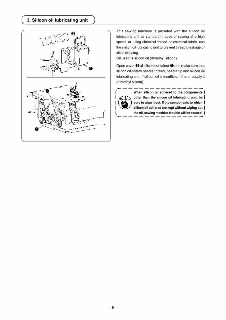
3. Silicon oil lubricating unit
This sewing machine is provided with the silicon oil lubricating unit as standard.In case of sewing at a high speed, or using chemical thread or chemical fabric, use the silicon oil lubricating unit to prevent thread breakage or stitch skipping. Oil used is silicon oil (dimethyl silicon).
Open cover ❷ of silicon container ❶ and make sure that silicon oil enters needle thread, needle tip and silicon oil lubricating unit. If silicon oil is insufficient there, supply it (dimethyl silicon).
When silicon oil adhered to the components other than the silicon oil lubricating unit, be sure to wipe it out. If the components to which silicon oil adhered are kept without wiping out the oil, sewing machine trouble will be caused.
❶
❶
❷
❷
– 10 –
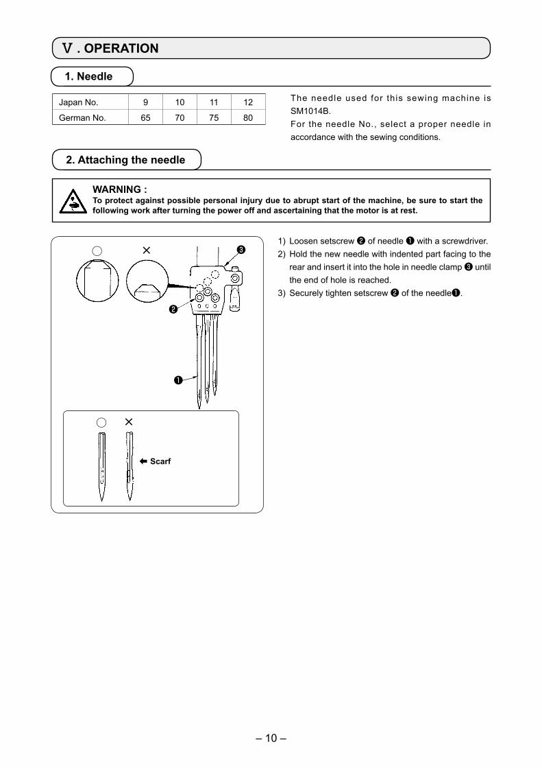
The needle used for this sewing machine is SM1014B.For the needle No., select a proper needle in accordance with the sewing conditions.
2. Attaching the needle
1) Loosen setscrew ❷ of needle ❶ with a screwdriver.2) Hold the new needle with indented part facing to the
rear and insert it into the hole in needle clamp ❸ until the end of hole is reached.
3) Securely tighten setscrew ❷ of the needle❶.
WARNING :To protect against possible personal injury due to abrupt start of the machine, be sure to start the following work after turning the power off and ascertaining that the motor is at rest.
1. Needle
Ⅴ . OPERATION
❶
❷
❸
➡ Scarf
○ ×
○ ×
Japan No. 9 10 11 12
German No. 65 70 75 80
– 11 –
❶
❸
B
C D
E
❷
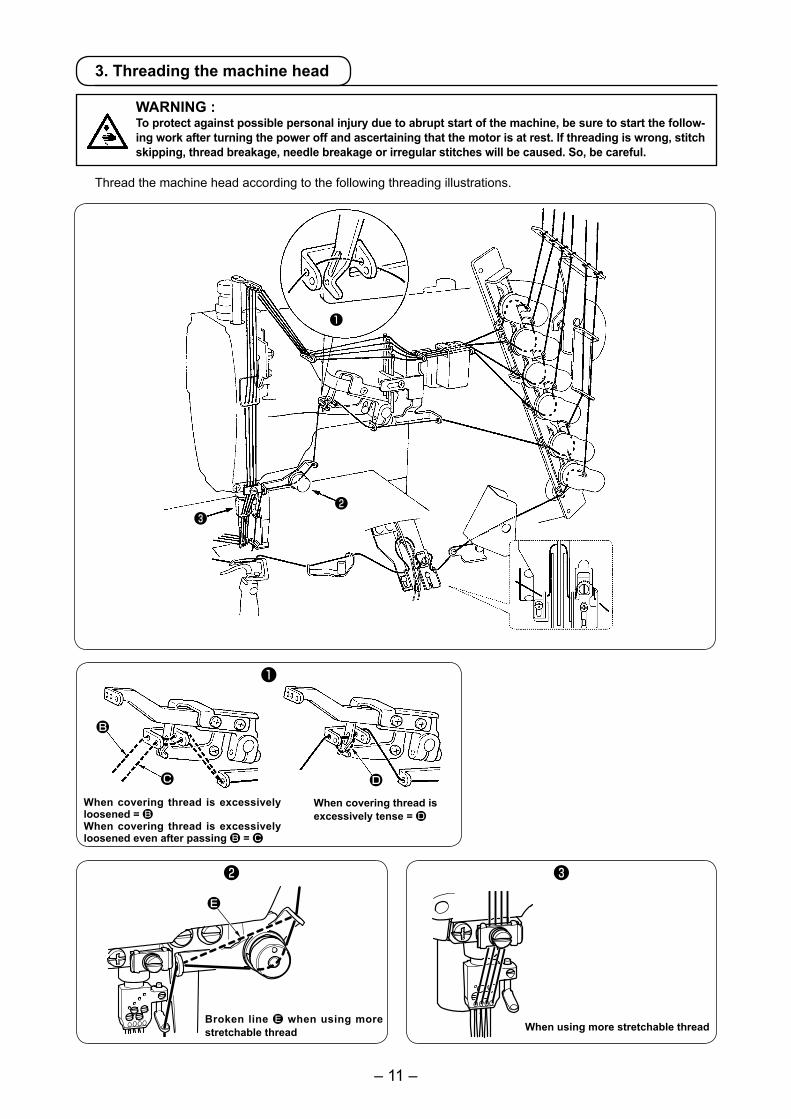
3. Threading the machine head
WARNING :To protect against possible personal injury due to abrupt start of the machine, be sure to start the follow-ing work after turning the power off and ascertaining that the motor is at rest. If threading is wrong, stitch skipping, thread breakage, needle breakage or irregular stitches will be caused. So, be careful.
When using more stretchable thread
When covering thread is excessively loosened = BWhen covering thread is excessively loosened even after passing B = C
When covering thread is excessively tense = D
Broken line E when using more stretchable thread
Thread the machine head according to the following threading illustrations.
❷
❶
❸
– 12 –
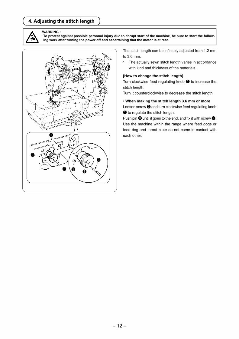
4. Adjusting the stitch length
WARNING :To protect against possible personal injury due to abrupt start of the machine, be sure to start the follow-ing work after turning the power off and ascertaining that the motor is at rest.
The stitch length can be infinitely adjusted from 1.2 mm to 3.6 mm.* The actually sewn stitch length varies in accordance
with kind and thickness of the materials.
[How to change the stitch length]Turn clockwise feed regulating knob ❶ to increase the stitch length.Turn it counterclockwise to decrease the stitch length.
• When making the stitch length 3.6 mm or moreLoosen screw ❷ and turn clockwise feed regulating knob ❶ to regulate the stitch length.Push pin ❸ until it goes to the end, and fix it with screw ❷.Use the machine within the range where feed dogs or feed dog and throat plate do not come in contact with each other.❶
❷
❷❸
❸
❶
– 13 –
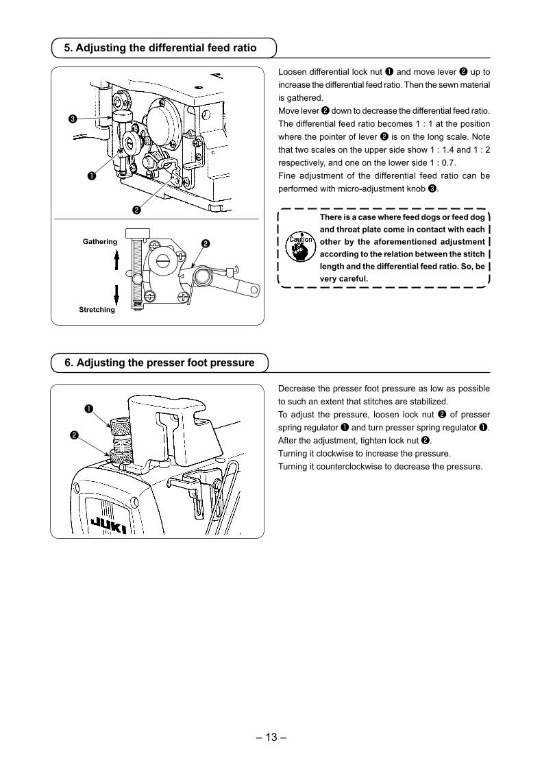
Loosen differential lock nut ❶ and move lever ❷ up to increase the differential feed ratio. Then the sewn material is gathered. Move lever ❷ down to decrease the differential feed ratio. The differential feed ratio becomes 1 : 1 at the position where the pointer of lever ❷ is on the long scale. Note that two scales on the upper side show 1 : 1.4 and 1 : 2 respectively, and one on the lower side 1 : 0.7.Fine adjustment of the differential feed ratio can be performed with micro-adjustment knob ❸.
There is a case where feed dogs or feed dog and throat plate come in contact with each other by the aforementioned adjustment according to the relation between the stitch length and the differential feed ratio. So, be very careful.
5. Adjusting the differential feed ratio
Gathering
Stretching
Decrease the presser foot pressure as low as possible to such an extent that stitches are stabilized.To adjust the pressure, loosen lock nut ❷ of presser spring regulator ❶ and turn presser spring regulator ❶. After the adjustment, tighten lock nut ❷.Turning it clockwise to increase the pressure.Turning it counterclockwise to decrease the pressure.
6. Adjusting the presser foot pressure
❶
❷
❸
❶
❷
❷
– 14 –
Decrease
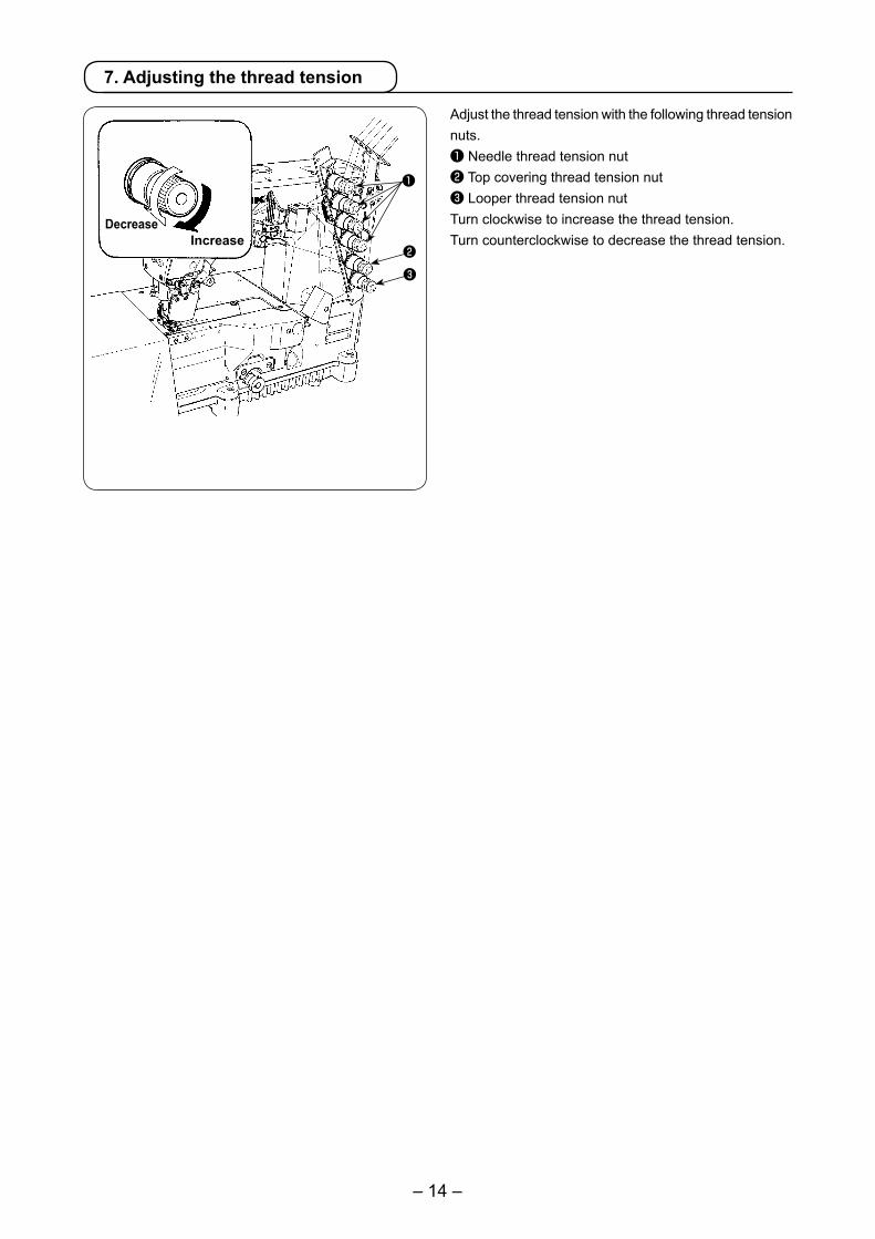
7. Adjusting the thread tension
Adjust the thread tension with the following thread tension nuts.❶ Needle thread tension nut❷ Top covering thread tension nut❸ Looper thread tension nutTurn clockwise to increase the thread tension.Turn counterclockwise to decrease the thread tension.Increase
❶
❷❸
– 15 –
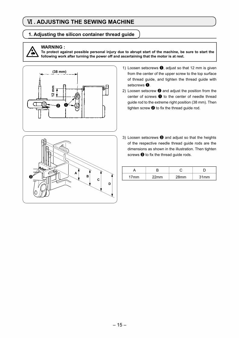
1) Loosen setscrews ❶, adjust so that 12 mm is given from the center of the upper screw to the top surface of thread guide, and tighten the thread guide with setscrews ❶.
2) Loosen setscrew ❷ and adjust the position from the center of screws ❶ to the center of needle thread guide rod to the extreme right position (38 mm). Then tighten screw ❷ to fix the thread guide rod.
A B C D
17mm 22mm 28mm 31mm
(38 mm)
12 m
m
❷ ❶
Ⅵ . ADJUSTING THE SEWING MACHINE
1. Adjusting the silicon container thread guide
WARNING :To protect against possible personal injury due to abrupt start of the machine, be sure to start the following work after turning the power off and ascertaining that the motor is at rest.
3) Loosen setscrews ❸ and adjust so that the heights of the respective needle thread guide rods are the dimensions as shown in the illustration. Then tighten screws ❸ to fix the thread guide rods.
AB
C❸
D
– 16 –
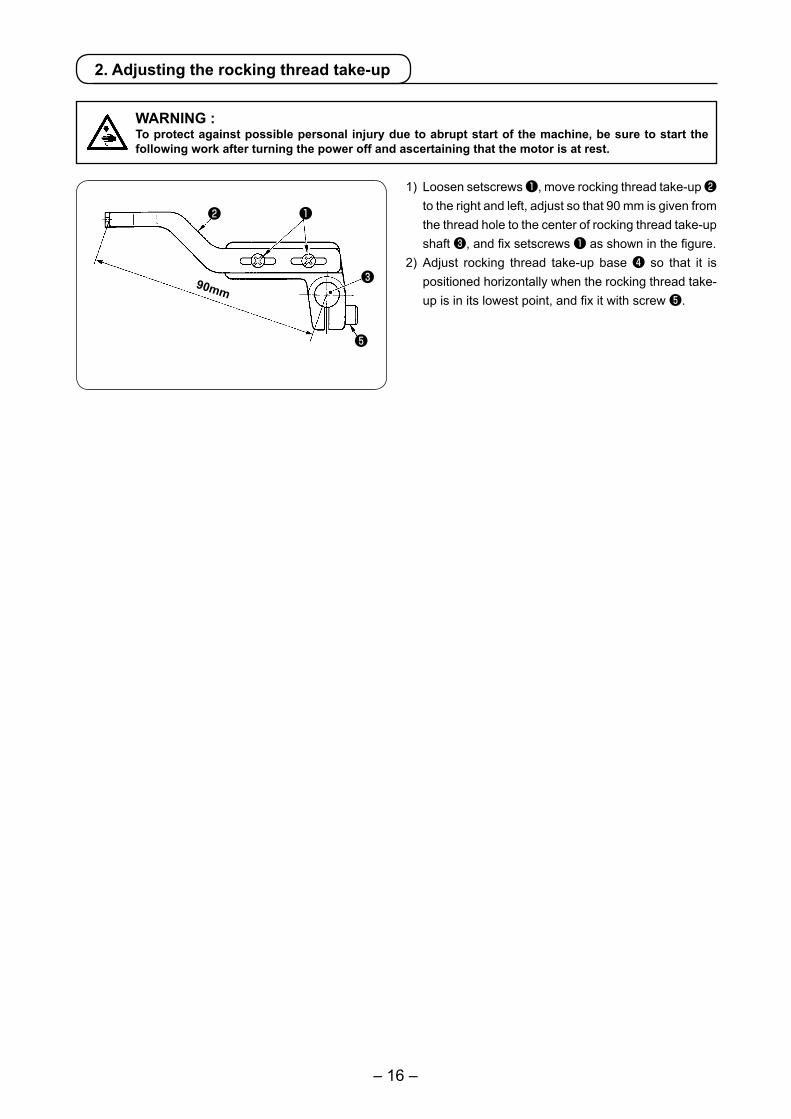
1) Loosen setscrews ❶, move rocking thread take-up ❷ to the right and left, adjust so that 90 mm is given from the thread hole to the center of rocking thread take-up shaft ❸, and fix setscrews ❶ as shown in the figure.
2) Adjust rocking thread take-up base ❹ so that it is positioned horizontally when the rocking thread take-up is in its lowest point, and fix it with screw ❺.
❶❷
❸
❺
90mm
WARNING :To protect against possible personal injury due to abrupt start of the machine, be sure to start the following work after turning the power off and ascertaining that the motor is at rest.
2. Adjusting the rocking thread take-up
– 17 –
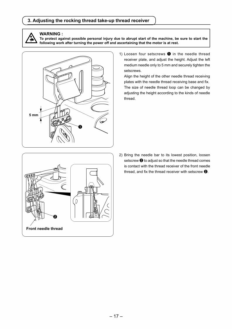
1) Loosen four setscrews ❶ in the needle thread receiver plate, and adjust the height. Adjust the left medium needle only to 5 mm and securely tighten the setscrews.
Align the height of the other needle thread receiving plates with the needle thread receiving base and fix.
The size of needle thread loop can be changed by adjusting the height according to the kinds of needle thread.
5 mm
❶
2) Bring the needle bar to its lowest position, loosen setscrew ❷ to adjust so that the needle thread comes is contact with the thread receiver of the front needle thread, and fix the thread receiver with setscrew ❷.
Front needle thread
❷
3. Adjusting the rocking thread take-up thread receiver
WARNING :To protect against possible personal injury due to abrupt start of the machine, be sure to start the following work after turning the power off and ascertaining that the motor is at rest.
– 18 –
❶
❷
❸
❹
❶
❷
❸
❹
❹
❷
❶
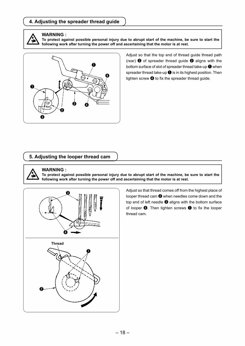
4. Adjusting the spreader thread guide
Adjust so that the top end of thread guide thread path (rear) ❸ of spreader thread guide ❷ aligns with the bottom surface of slot of spreader thread take-up ❶ when spreader thread take-up ❶ is in its highest position. Then tighten screw ❹ to fix the spreader thread guide.
WARNING :To protect against possible personal injury due to abrupt start of the machine, be sure to start the following work after turning the power off and ascertaining that the motor is at rest.
5. Adjusting the looper thread cam
Adjust so that thread comes off from the highest place of looper thread cam ❷ when needles come down and the top end of left needle ❸ aligns with the bottom surface of looper ❹. Then tighten screws ❶ to fix the looper thread cam.
Thread
WARNING :To protect against possible personal injury due to abrupt start of the machine, be sure to start the following work after turning the power off and ascertaining that the motor is at rest.
– 19 –
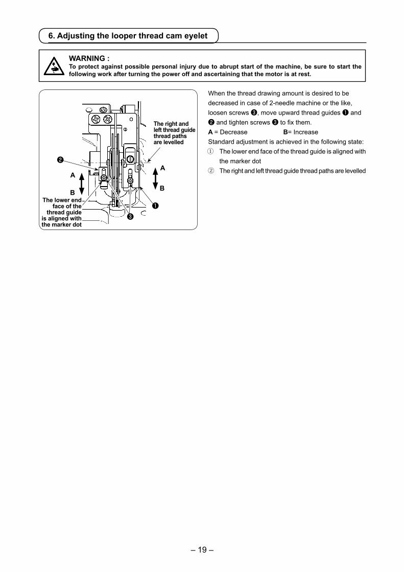
6. Adjusting the looper thread cam eyelet
When the thread drawing amount is desired to be decreased in case of 2-needle machine or the like, loosen screws ❸, move upward thread guides ❶ and ❷ and tighten screws ❸ to fix them.A = Decrease B= IncreaseStandard adjustment is achieved in the following state:① The lower end face of the thread guide is aligned with
the marker dot② The right and left thread guide thread paths are levelledA
❶
❷
❸
B
A
B
The right and left thread guide thread paths are levelled
The lower end face of the
thread guide is aligned with the marker dot
WARNING :To protect against possible personal injury due to abrupt start of the machine, be sure to start the following work after turning the power off and ascertaining that the motor is at rest.
– 20 –
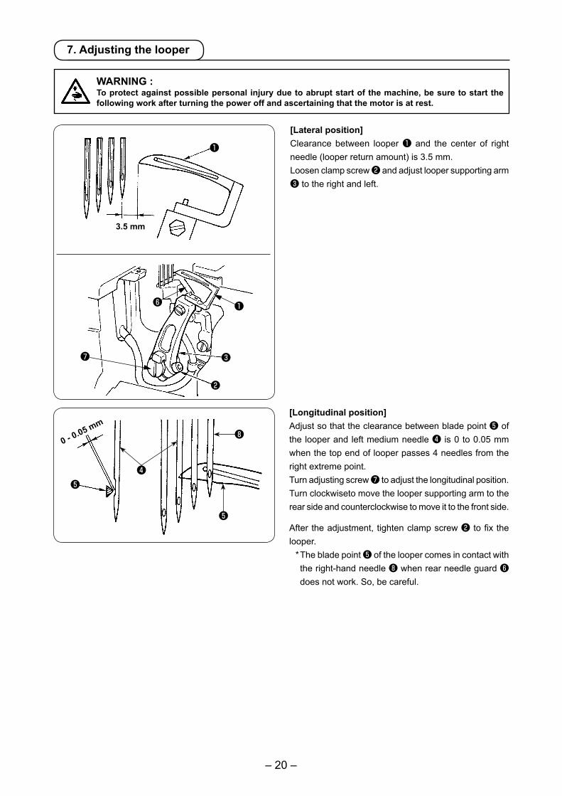
[Longitudinal position]Adjust so that the clearance between blade point ❺ of the looper and left medium needle ❹ is 0 to 0.05 mm when the top end of looper passes 4 needles from the right extreme point.Turn adjusting screw ❼ to adjust the longitudinal position.Turn clockwiseto move the looper supporting arm to the rear side and counterclockwise to move it to the front side.
After the adjustment, tighten clamp screw ❷ to fix the looper. * The blade point ❺ of the looper comes in contact with
the right-hand needle ❽ when rear needle guard ❻ does not work. So, be careful.
0 - 0.05 mm
❶
❷
❸
3.5 mm
❶❻
❼
7. Adjusting the looper
[Lateral position]Clearance between looper ❶ and the center of right needle (looper return amount) is 3.5 mm.Loosen clamp screw ❷ and adjust looper supporting arm ❸ to the right and left.
WARNING :To protect against possible personal injury due to abrupt start of the machine, be sure to start the following work after turning the power off and ascertaining that the motor is at rest.
❺❹
❺
❽
– 21 –
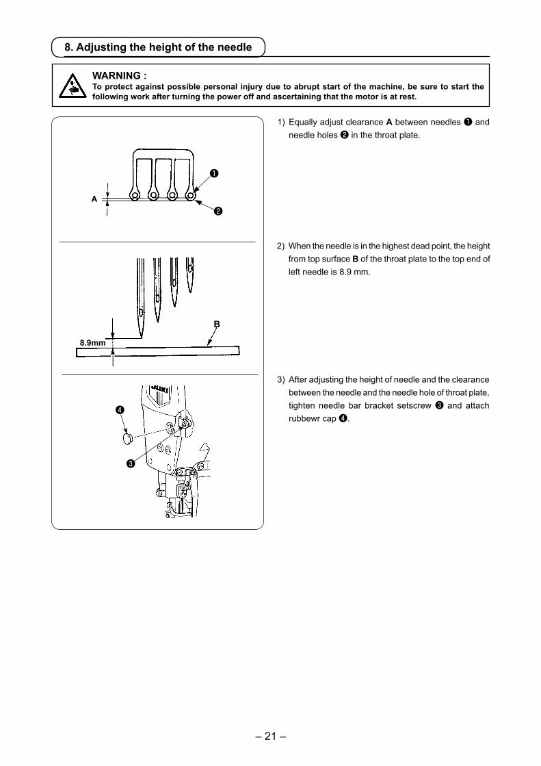
2) When the needle is in the highest dead point, the height from top surface B of the throat plate to the top end of left needle is 8.9 mm.
1) Equally adjust clearance A between needles ❶ and needle holes ❷ in the throat plate.
A
❶
❷
8.9mm
B
8. Adjusting the height of the needle
WARNING :To protect against possible personal injury due to abrupt start of the machine, be sure to start the following work after turning the power off and ascertaining that the motor is at rest.
❸
❹
3) After adjusting the height of needle and the clearance between the needle and the needle hole of throat plate, tighten needle bar bracket setscrew ❸ and attach rubbewr cap ❹.
– 22 –
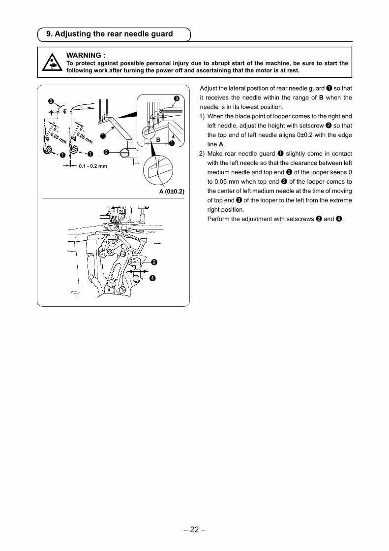
Adjust the lateral position of rear needle guard ❶ so that it receives the needle within the range of B when the needle is in its lowest position.1) When the blade point of looper comes to the right end
left needle, adjust the height with setscrew ❷ so that the top end of left needle aligns 0±0.2 with the edge line A.
2) Make rear needle guard ❶ slightly come in contact with the left needle so that the clearance between left medium needle and top end ❸ of the looper keeps 0 to 0.05 mm when top end ❸ of the looper comes to the center of left medium needle at the time of moving of top end ❸ of the looper to the left from the extreme right position.
Perform the adjustment with setscrews ❷ and ❹.
9. Adjusting the rear needle guard
WARNING :To protect against possible personal injury due to abrupt start of the machine, be sure to start the following work after turning the power off and ascertaining that the motor is at rest.
0 - 0.05 mm
0 -0.05 mm
0.1 - 0.2 mm
❷
❹
❶ ❶ ❷
❸
A (0±0.2)
B
❸
❶❶
– 23 –
10. Relation between the rocking thread take-up timing and the needle thread loop
❸❹
❷
❶
8 mm
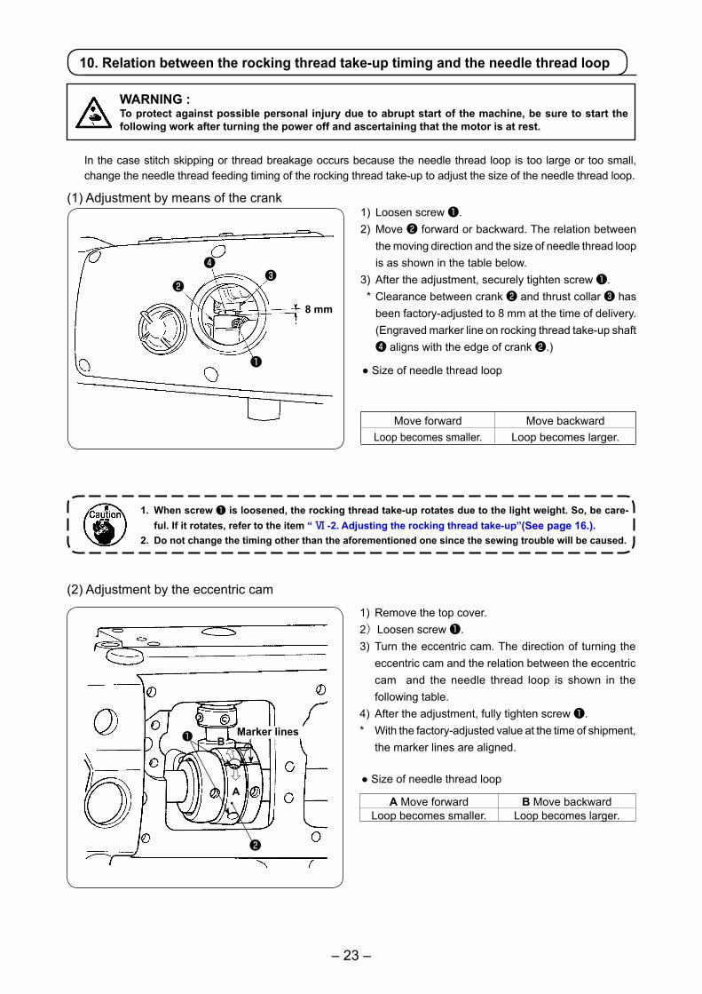
In the case stitch skipping or thread breakage occurs because the needle thread loop is too large or too small, change the needle thread feeding timing of the rocking thread take-up to adjust the size of the needle thread loop.
1) Loosen screw ❶.2) Move ❷ forward or backward. The relation between
the moving direction and the size of needle thread loop is as shown in the table below.
3) After the adjustment, securely tighten screw ❶. * Clearance between crank ❷ and thrust collar ❸ has
been factory-adjusted to 8 mm at the time of delivery. (Engraved marker line on rocking thread take-up shaft ❹ aligns with the edge of crank ❷.)
● Size of needle thread loop
1. When screw ❶ is loosened, the rocking thread take-up rotates due to the light weight. So, be care-ful. If it rotates, refer to the item “ Ⅵ -2. Adjusting the rocking thread take-up”(See page 16.).
2. Do not change the timing other than the aforementioned one since the sewing trouble will be caused.
Move forward Move backwardLoop becomes smaller. Loop becomes larger.
(2) Adjustment by the eccentric cam
1) Remove the top cover.2)Loosen screw ❶.3) Turn the eccentric cam. The direction of turning the
eccentric cam and the relation between the eccentric cam and the needle thread loop is shown in the following table.
4) After the adjustment, fully tighten screw ❶.* With the factory-adjusted value at the time of shipment,
the marker lines are aligned.
● Size of needle thread loop
A Move forward B Move backwardLoop becomes smaller. Loop becomes larger.
(1) Adjustment by means of the crank
❶ B
A
Marker lines
⇧⇩
WARNING :To protect against possible personal injury due to abrupt start of the machine, be sure to start the following work after turning the power off and ascertaining that the motor is at rest.
❷
– 24 –
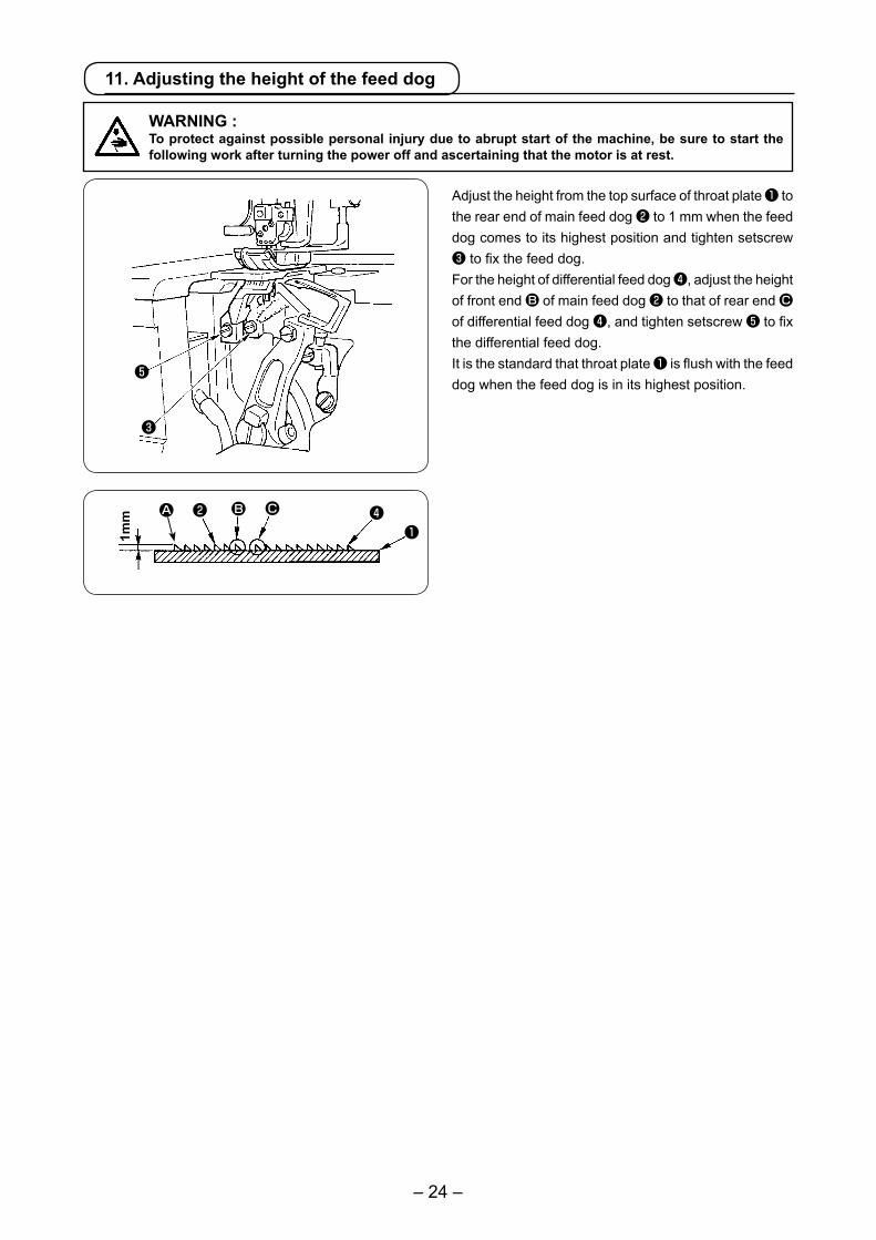
Adjust the height from the top surface of throat plate ❶ to the rear end of main feed dog ❷ to 1 mm when the feed dog comes to its highest position and tighten setscrew ❸ to fix the feed dog. For the height of differential feed dog ❹, adjust the height of front end B of main feed dog ❷ to that of rear end C of differential feed dog ❹, and tighten setscrew ❺ to fix the differential feed dog. It is the standard that throat plate ❶ is flush with the feed dog when the feed dog is in its highest position.
11. Adjusting the height of the feed dog
WARNING :To protect against possible personal injury due to abrupt start of the machine, be sure to start the following work after turning the power off and ascertaining that the motor is at rest.
❶❷
❸
❹B C
❺
1mm A
– 25 –
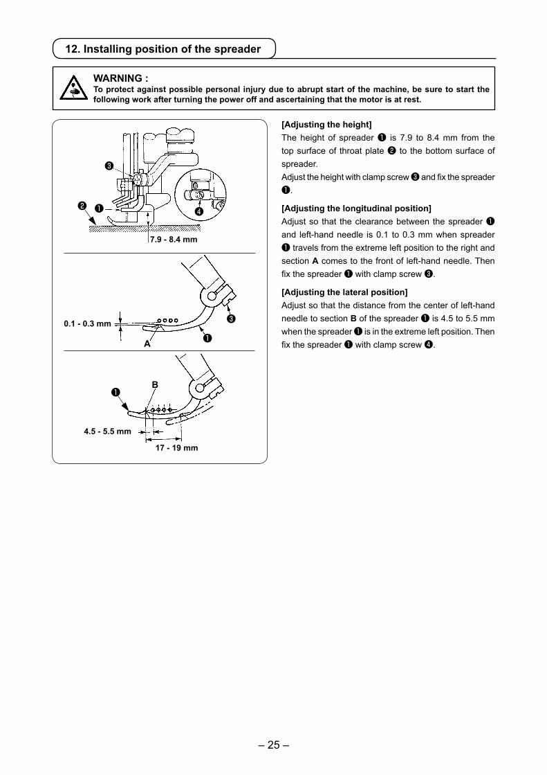
[Adjusting the height]The height of spreader ❶ is 7.9 to 8.4 mm from the top surface of throat plate ❷ to the bottom surface of spreader.Adjust the height with clamp screw ❸ and fix the spreader ❶.
[Adjusting the longitudinal position]Adjust so that the clearance between the spreader ❶ and left-hand needle is 0.1 to 0.3 mm when spreader ❶ travels from the extreme left position to the right and section A comes to the front of left-hand needle. Then fix the spreader ❶ with clamp screw ❸.
[Adjusting the lateral position]Adjust so that the distance from the center of left-hand needle to section B of the spreader ❶ is 4.5 to 5.5 mm when the spreader ❶ is in the extreme left position. Then fix the spreader ❶ with clamp screw ❹.
0.1 - 0.3 mm
4.5 - 5.5 mm
17 - 19 mm
7.9 - 8.4 mm
❶
❸
❹
B
❷
A ❶
❸
❶
12. Installing position of the spreader
WARNING :To protect against possible personal injury due to abrupt start of the machine, be sure to start the following work after turning the power off and ascertaining that the motor is at rest.

– 26 –
[Spreader thread guide]Adjust so that the clearance between spreader thread guide ❷ and spreader ❶ is 0.4 to 1.0 mm. Then fix the spreader thread guide with setscrews ❸. * Adjust so that the center of slot A of thread guide ❷
aligns with blade point B of spreader when spreader ❶ is in the extreme right position. In addition, allow the spreader thread guide ❷ to come near the needle clamp to such an extent that the spreader thread guide does not interfere with the needle clamp.
[Needle clamp thread guide]Adjust so that the center of thread hole of needle clamp thread guide ❹ and spreader thread guide ❷aligns with center C of slot A when the needle is in the lowest position. * At this time, adjust so that the clearance between
needle clamp thread guide ❹ and spreader thread guide ❷ is 0.8 to 1.2 mm. Then fix the needle clamp thread guide with setscrew ❺. 0.8 - 1.2 mm
0.4 - 1.0 mm
0.1
– 0.
3 m
m
❶
❷ ❸
13. Adjusting the spreader thread guide and the needle clamp thread guide
WARNING :To protect against possible personal injury due to abrupt start of the machine, be sure to start the following work after turning the power off and ascertaining that the motor is at rest.
14. Adjusting the front needle guard
Adjust so that the clearance between the needles and front needle guard ❷ is 0.1 to 0.3 mm when looper ❶ travels from the extreme right position to the left and passes the rear side of the respective needles. Then fix the front needle guard ❷ with setscrew ❸. * Allow front needle guard ❷ to come to the needle
as near as possible within the range where needle thread smoothly passes in accordance with the kind or thickness of thread.
WARNING :To protect against possible personal injury due to abrupt start of the machine, be sure to start the following work after turning the power off and ascertaining that the motor is at rest.
❶
❷
❸
❹❺
A
B
C
❷
❹❺
❶❷
– 27 –
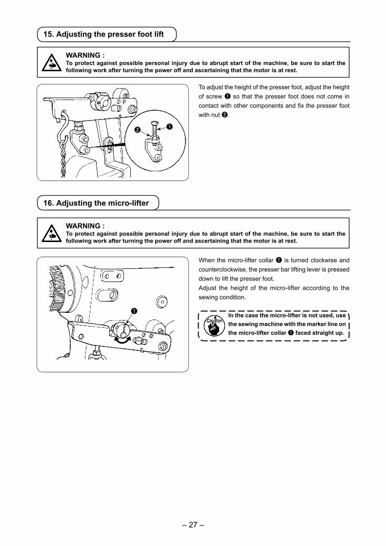
To adjust the height of the presser foot, adjust the height of screw ❶ so that the presser foot does not come in contact with other components and fix the presser foot with nut ❷.
15. Adjusting the presser foot lift
When the micro-lifter collar ❶ is turned clockwise and counterclockwise, the presser bar lifting lever is pressed down to lift the presser foot.Adjust the height of the micro-lifter according to the sewing condition.
In the case the micro-lifter is not used, use the sewing machine with the marker line on the micro-lifter collar ❶ faced straight up.
❶❷
❶
16. Adjusting the micro-lifter
WARNING :To protect against possible personal injury due to abrupt start of the machine, be sure to start the following work after turning the power off and ascertaining that the motor is at rest.
WARNING :To protect against possible personal injury due to abrupt start of the machine, be sure to start the following work after turning the power off and ascertaining that the motor is at rest.
– 28 –
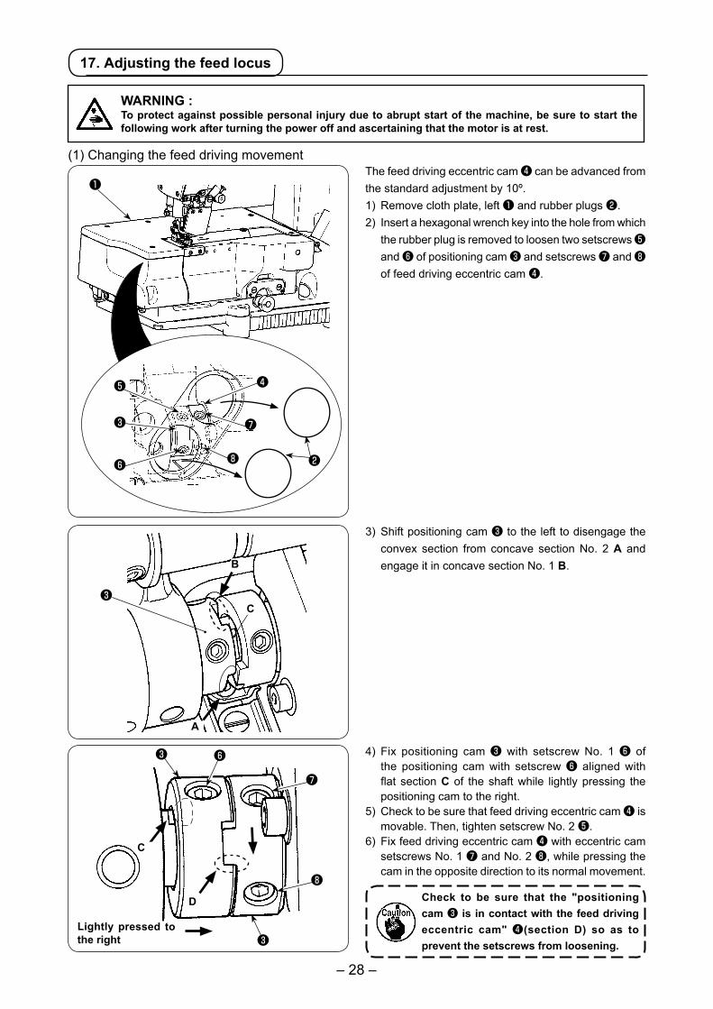
The feed driving eccentric cam ❹ can be advanced from the standard adjustment by 10º.1) Remove cloth plate, left ❶ and rubber plugs ❷.2) Insert a hexagonal wrench key into the hole from which
the rubber plug is removed to loosen two setscrews ❺ and ❻ of positioning cam ❸ and setscrews ❼ and ❽ of feed driving eccentric cam ❹.
4) Fix positioning cam ❸ with setscrew No. 1 ❻ of the positioning cam with setscrew ❻ aligned with flat section C of the shaft while lightly pressing the positioning cam to the right.
5) Check to be sure that feed driving eccentric cam ❹ is movable. Then, tighten setscrew No. 2 ❺.
6) Fix feed driving eccentric cam ❹ with eccentric cam setscrews No. 1 ❼ and No. 2 ❽, while pressing the cam in the opposite direction to its normal movement.
Check to be sure that the "positioning cam ❸ is in contact with the feed driving eccentric cam" ❹(section D) so as to prevent the setscrews from loosening.
❹
❻
Lightly pressed to the right
D
❼
❺
❻
❼
❽
❸
❽
C
❸
❸
❶
❷
(1) Changing the feed driving movement
3) Shift positioning cam ❸ to the left to disengage the convex section from concave section No. 2 A and engage it in concave section No. 1 B.
17. Adjusting the feed locus
❸
B
A
WARNING :To protect against possible personal injury due to abrupt start of the machine, be sure to start the following work after turning the power off and ascertaining that the motor is at rest.
C
– 29 –
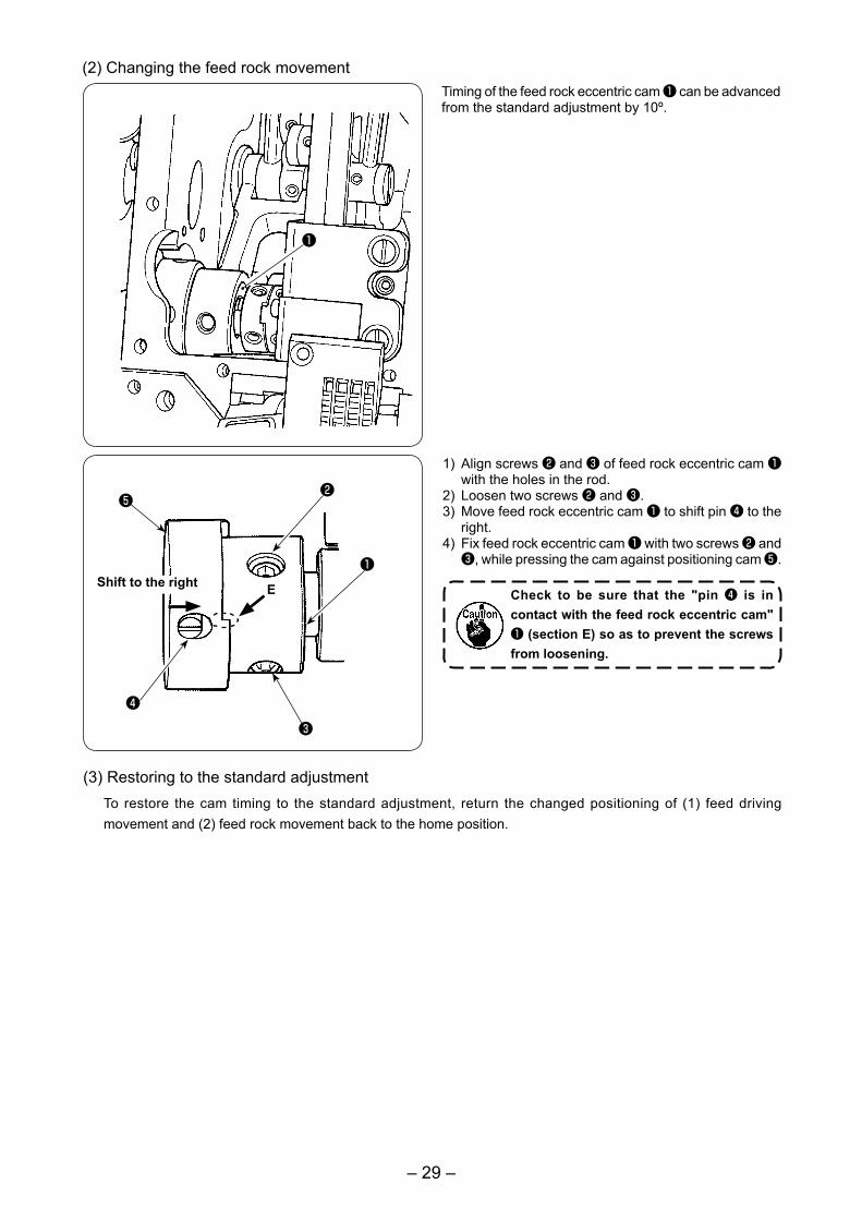
1) Align screws ❷ and ❸ of feed rock eccentric cam ❶ with the holes in the rod.
2) Loosen two screws ❷ and ❸.3) Move feed rock eccentric cam ❶ to shift pin ❹ to the
right.4) Fix feed rock eccentric cam ❶ with two screws ❷ and
❸, while pressing the cam against positioning cam ❺.
Check to be sure that the "pin ❹ is in contact with the feed rock eccentric cam" ❶ (section E) so as to prevent the screws from loosening.
❷
❸
Shift to the right❶
E
❹
❺
Timing of the feed rock eccentric cam ❶ can be advanced from the standard adjustment by 10º.
(2) Changing the feed rock movement
(3) Restoring to the standard adjustmentTo restore the cam timing to the standard adjustment, return the changed positioning of (1) feed driving movement and (2) feed rock movement back to the home position.
❶
– 30 –
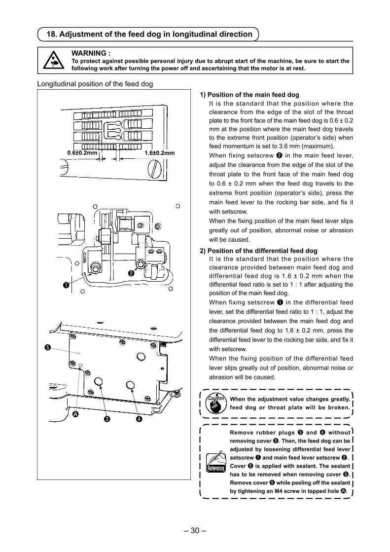
18. Adjustment of the feed dog in longitudinal direction
Longitudinal position of the feed dog1) Position of the main feed dog
It is the standard that the posit ion where the clearance from the edge of the slot of the throat plate to the front face of the main feed dog is 0.6 ± 0.2 mm at the position where the main feed dog travels to the extreme front position (operator’s side) when feed momentum is set to 3.6 mm (maximum).When fixing setscrew ❷ in the main feed lever, adjust the clearance from the edge of the slot of the throat plate to the front face of the main feed dog to 0.6 ± 0.2 mm when the feed dog travels to the extreme front position (operator’s side), press the main feed lever to the rocking bar side, and fix it with setscrew.When the fixing position of the main feed lever slips greatly out of position, abnormal noise or abrasion will be caused.
2) Position of the differential feed dogIt is the standard that the posit ion where the clearance provided between main feed dog and differential feed dog is 1.6 ± 0.2 mm when the differential feed ratio is set to 1 : 1 after adjusting the position of the main feed dog.When fixing setscrew ❶ in the differential feed lever, set the differential feed ratio to 1 : 1, adjust the clearance provided between the main feed dog and the differential feed dog to 1.6 ± 0.2 mm, press the differential feed lever to the rocking bar side, and fix it with setscrew.When the fixing position of the differential feed lever slips greatly out of position, abnormal noise or abrasion will be caused.
When the adjustment value changes greatly, feed dog or throat plate will be broken.
Remove rubber plugs ❸ and ❹ without removing cover ❺. Then, the feed dog can be adjusted by loosening differential feed lever setscrew ❶ and main feed lever setscrew ❷.Cover ❺ is applied with sealant. The sealant has to be removed when removing cover ❺. Remove cover ❺ while peeling off the sealant by tightening an M4 screw in tapped hole A.
WARNING :To protect against possible personal injury due to abrupt start of the machine, be sure to start the following work after turning the power off and ascertaining that the motor is at rest.
1.6±0.2mm0.6±0.2mm
❸ ❹
❶
❷
❺
A
– 31 –
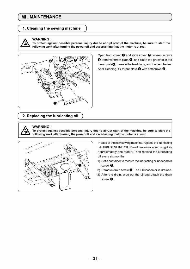
1. Cleaning the sewing machine
Open front cover ❶ and slide cover ❷, loosen screws ❸, remove throat plate ❹, and clean the grooves in the throat plate❹, those in the feed dogs, and the peripheries.After cleaning, fix throat plate ❹ with setscrews ❸.
2. Replacing the lubricating oil
In case of the new sewing machine, replace the lubricating oil (JUKI GENUINE OIL 18) with new one after using it for approximately one month. Then replace the lubricating oil every six months.1) Set a container to receive the lubricating oil under drain
screw ❶.2) Remove drain screw ❶. The lubrication oil is drained.3) After the drain, wipe out the oil and attach the drain
screw ❶.
❶
Ⅶ . MAINTENANCE
❶
❷
❸
❹
WARNING :To protect against possible personal injury due to abrupt start of the machine, be sure to start the following work after turning the power off and ascertaining that the motor is at rest.
WARNING :To protect against possible personal injury due to abrupt start of the machine, be sure to start the following work after turning the power off and ascertaining that the motor is at rest.

– 32 –
3. Inspecting and replacing the oil filter
❶
❷
❸
Normal lubrication cannot be performed if dust collects in oil filter ❶ . Inspect it every 6 months.
1) Remove oil filter cap ❷, and draw out oil filter ❶ to inspect it.
2) When oil filter ❶ is clogged with dust, replace it with a new one.
3) After the replacement, fix the filter cap ❷ with screws ❸.
When removing the oil filter cap, lubricating oil collected in the filter will leak out. So, be careful.
WARNING :To protect against possible personal injury due to abrupt start of the machine, be sure to start the following work after turning the power off and ascertaining that the motor is at rest.