meyer’s equipment mfg. corp.emcspreaders.com/pdf/twin_twister/vb750_meyers... · meyer’s...
TRANSCRIPT

Manufactured in DORCHESTER, WI by
MEYER’S EQUIPMENTMFG. CORP.
INSTRUCTION AND PARTS BOOK NO. 10-18-11
DO NOT operate this Spreader until you haveread this book
NEVER repair or clean this Spreader while PTOis engaged
HEAVY DUTY VERTICAL BEATER MANURE SPREADERSMODEL: VB750
INTRODUCTIONCongratulations on the purchase of your new Meyer’sManure Spreader. With its optional equipment this isthe simplest, most flexible system on the market today.With proper operation and preventative maintenance itwill last for years.
This SAFETY ALERT SYMBOL means AT-TENTION! BE CAREFUL! YOUR SAFETY IS IN-VOLVED! It stresses an attitude of HEADS UP FORSAFETY. When you see this symbol, be alert to thepossibility of PERSONAL INJURY and carefully readthe message that follows.
WARNING:NEVER OPERATE WITHOUT ALL COVERS,SHIELDS AND GUARDS IN PLACE. KEEP HANDS,FEET AND CLOTHING AWAY FROM MOVINGPARTS. SOME COVERS AND GUARDS HAVE BEENREMOVED FOR ILLUSTRATIVE PURPOSES ONLYIN THIS MANUAL. FAILURE TO HEED MAY RESULTIN SERIOUS PERSONAL INJURY OR DEATH.
At the front of this manual is a Product Registrationand Inspection Certificate. Be sure your dealer hascompleted this certificate and forwarded a copy to themanufacturer to validate the manufacturer’s warranty.
The product model and serial number are recorded onthis certificate for your convenience and for properidentification of your spreader by your dealer and themanufacturer when ordering repair parts.
The serial number plate is found on the front center ofthe spreader, just below the Implement PTO shaft. Forinformation on ordering repair parts, refer to the repairparts section of this manual. Orders must list the com-plete description, correct part number, and totalamount required.
All references to right hand and left hand apply to theproduct as viewed from the rear of the machine andfacing the direction of forward travel.
You are urged to study this manual and follow the in-structions carefully. Your efforts will be repaid in betteroperation and service as well as a savings in time andrepair expense. Failure to read this manual and under-stand the machine could lead to serious injury. If youdo not understand instructions in this manual, contacteither your dealer or Meyer’s Equipment Manufac-turing Corp. at Dorchester, WI 54425.
This supercedes all previous published instructions
MODEL: VB750 Page 2
TABLE OF CONTENTSINTRODUCTION . . . . . . . . . . . . . . . . . . . . . . . . . . . . . . . . . . . . . . . 2SAFETY. . . . . . . . . . . . . . . . . . . . . . . . . . . . . . . . . . . . . . . . . . . . 5SAFETY SIGNS . . . . . . . . . . . . . . . . . . . . . . . . . . . . . . . . . . . . . . . 7MANURE SPREADER SAFETY . . . . . . . . . . . . . . . . . . . . . . . . . . . . . . . 9MANDATORY SAFETY SHUTDOWN PROCEDURE. . . . . . . . . . . . . . . . . . . . 10PRE-OPERATION. . . . . . . . . . . . . . . . . . . . . . . . . . . . . . . . . . . . . . 11
General . . . . . . . . . . . . . . . . . . . . . . . . . . . . . . . . . . . . . . . . . 11Tractor Hitch And PTO Requirements . . . . . . . . . . . . . . . . . . . . . . . . . . 11
ADMA Recommendations: · · · · · · · · · · · · · · · · · · · · · · · · · · · · · · 11Tractor Size Requirements. . . . . . . . . . . . . . . . . . . . . . . . . . . . . . . . 12
Tractor Towing Size Requirements· · · · · · · · · · · · · · · · · · · · · · · · · · 12Material Estimated Weight Per Cubic Foot · · · · · · · · · · · · · · · · · · · · · · 12
Theory Of Operation . . . . . . . . . . . . . . . . . . . . . . . . . . . . . . . . . . . 12Hydraulic System . . . . . . . . . . . . . . . . . . . . . . . . . . . . . . . . . . . . 12
General · · · · · · · · · · · · · · · · · · · · · · · · · · · · · · · · · · · · · · · · 12Converting A Spreader From Closed Center To Open Center . . . . . . . . . . . . . . 13
To Convert Standard Non Flow Controlled Closed Center System To OpenCenter · · · · · · · · · · · · · · · · · · · · · · · · · · · · · · · · · · · · · · · 14
To Convert Optional On Board Flow Controlled Closed Center System ToOpen Center · · · · · · · · · · · · · · · · · · · · · · · · · · · · · · · · · · · 14
Electric Control Installation for Optional On Board Flow Controlled System . . . . . . . 15Transporting . . . . . . . . . . . . . . . . . . . . . . . . . . . . . . . . . . . . . . . 16
General · · · · · · · · · · · · · · · · · · · · · · · · · · · · · · · · · · · · · · · · 16Use Safety Chain· · · · · · · · · · · · · · · · · · · · · · · · · · · · · · · · · · · 16Use Lights · · · · · · · · · · · · · · · · · · · · · · · · · · · · · · · · · · · · · · 16
OPERATION . . . . . . . . . . . . . . . . . . . . . . . . . . . . . . . . . . . . . . . . 17Tractor Hookup . . . . . . . . . . . . . . . . . . . . . . . . . . . . . . . . . . . . . 17Loading . . . . . . . . . . . . . . . . . . . . . . . . . . . . . . . . . . . . . . . . . 17Unloading . . . . . . . . . . . . . . . . . . . . . . . . . . . . . . . . . . . . . . . . 17Mandatory Safety Shutdown Procedure . . . . . . . . . . . . . . . . . . . . . . . . . 18
MAINTENANCE, ADJUSTMENTS & LUBRICATION . . . . . . . . . . . . . . . . . . . . 19Wheel And Tire Maintenance And Repair . . . . . . . . . . . . . . . . . . . . . . . . 19Lock Ring Rim . . . . . . . . . . . . . . . . . . . . . . . . . . . . . . . . . . . . . . 19Rear-Automatic Over Running Clutch . . . . . . . . . . . . . . . . . . . . . . . . . . 19Mandatory Safety Shutdown Procedure. . . . . . . . . . . . . . . . . . . . . . . . . 19
Adjustments . . . . . . . . . . . . . . . . . . . . . . . . . . . . . . . . . . . . . . . 20Apron Chain · · · · · · · · · · · · · · · · · · · · · · · · · · · · · · · · · · · · · 20
Lubrication . . . . . . . . . . . . . . . . . . . . . . . . . . . . . . . . . . . . . . . . 20Cleaning And Storage . . . . . . . . . . . . . . . . . . . . . . . . . . . . . . . . . . 22
REPAIR PARTS . . . . . . . . . . . . . . . . . . . . . . . . . . . . . . . . . . . . . . . 24Main Frame & Box Parts · · · · · · · · · · · · · · · · · · · · · · · · · · · · · · · · · 24Hydraulic End Gate & Related Parts · · · · · · · · · · · · · · · · · · · · · · · · · · · 26Jack Assembly · · · · · · · · · · · · · · · · · · · · · · · · · · · · · · · · · · · · · · 28Axles, Wheels, Spindles And Related Parts · · · · · · · · · · · · · · · · · · · · · · · 30
Page 3 MODEL: VB750
1 3/4” Drive Train · · · · · · · · · · · · · · · · · · · · · · · · · · · · · · · · · · · · 32Apron & Related Parts · · · · · · · · · · · · · · · · · · · · · · · · · · · · · · · · · · 34Apron & Related Parts · · · · · · · · · · · · · · · · · · · · · · · · · · · · · · · · · · 36Lube Bank · · · · · · · · · · · · · · · · · · · · · · · · · · · · · · · · · · · · · · · · 3815mm Beater Head Assembly, Standard · · · · · · · · · · · · · · · · · · · · · · · · 40Vertical Beaters & Related Parts· · · · · · · · · · · · · · · · · · · · · · · · · · · · · 42Apron Drive Gearbox· · · · · · · · · · · · · · · · · · · · · · · · · · · · · · · · · · · 44Removable CV Telescoping Universal Joint Assembly With Guard, Trailer To Tractor · · · · 4635E Universal Joint, Telescoping Assembly w/ Guard - Rear With Over-Running Clutch · · · · 47Standard Highway Lighting With Amber Side Light · · · · · · · · · · · · · · · · · · · 48Hydraulic Assembly - Electric Flow Control - Closed Center· · · · · · · · · · · · · · · 50Hydraulic Assembly-No Electric Flow Control-Closed Center · · · · · · · · · · · · · · · 54Hydraulic Assembly - No Electric Flow Control - Open Center· · · · · · · · · · · · · · 56Weigh Scale · · · · · · · · · · · · · · · · · · · · · · · · · · · · · · · · · · · · · · · 58
LIMITED WARRANTY STATEMENT . . . . . . . . . . . . . . . . . . . . . . . . . . . . 60
MODEL: VB750 Page 4

SAFETY
Page 5 MODEL: VB750
A brief definition of signal words that may be used inthis manual:
DANGER: Indicates an imminently hazardous sit-uation that, if not avoided, will result in serious injury ordeath.
WARNING: Indicates a potentially hazardous sit-uation that, if not avoided, could result in death or seri-ous injury, and includes hazards that are exposed whenguards are removed.
CAUTION: Indicates a potentially hazardous situ-ation that, if not avoided, may result in minor or moder-ate injury.
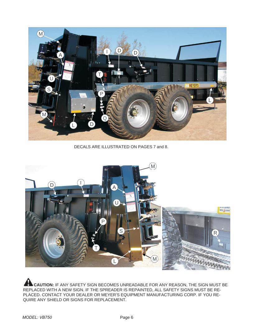
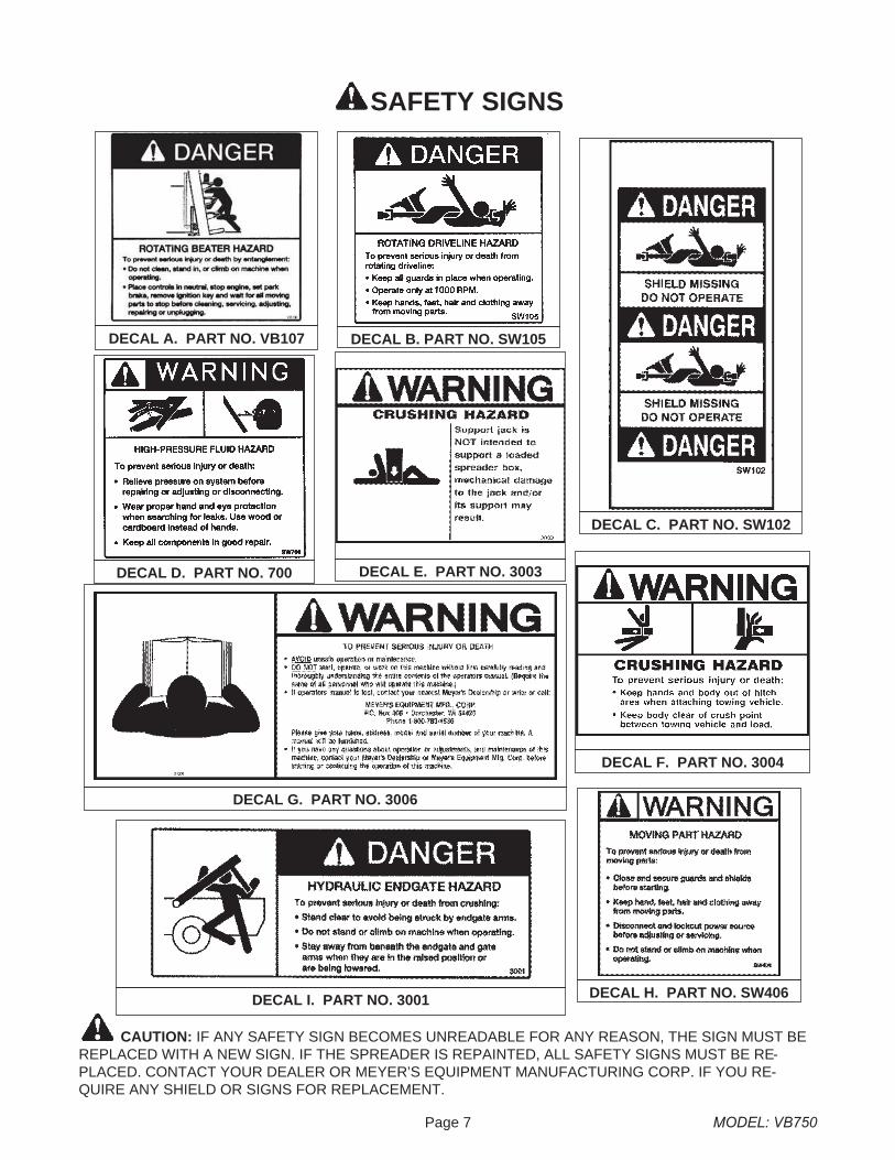
CAUTION: IF ANY SAFETY SIGN BECOMES UNREADABLE FOR ANY REASON, THE SIGN MUST BEREPLACED WITH A NEW SIGN. IF THE SPREADER IS REPAINTED, ALL SAFETY SIGNS MUST BE RE-PLACED. CONTACT YOUR DEALER OR MEYER’S EQUIPMENT MANUFACTURING CORP. IF YOU RE-QUIRE ANY SHIELD OR SIGNS FOR REPLACEMENT.
DECALS ARE ILLUSTRATED ON PAGES 7 and 8.
E
G
Also undershield
V
Located on DrivelineShields under spreader
H
F
B
B
Typical Illustration
D
ON PTO FRONTHALF
J K
C
MODEL: VB750 Page 6
CAUTION: IF ANY SAFETY SIGN BECOMES UNREADABLE FOR ANY REASON, THE SIGN MUST BEREPLACED WITH A NEW SIGN. IF THE SPREADER IS REPAINTED, ALL SAFETY SIGNS MUST BE RE-PLACED. CONTACT YOUR DEALER OR MEYER’S EQUIPMENT MANUFACTURING CORP. IF YOU RE-QUIRE ANY SHIELD OR SIGNS FOR REPLACEMENT.
R
A
U
ID
L M
S
M
T
P
I D
T
LQ
P
A
M
L
M
DECALS ARE ILLUSTRATED ON PAGES 7 and 8.
S
U
D
D
SAFETY SIGNS
Page 7 MODEL: VB750
DECAL A. PART NO. VB107 DECAL B. PART NO. SW105
DECAL C. PART NO. SW102
DECAL I. PART NO. 3001
DECAL D. PART NO. 700 DECAL E. PART NO. 3003
DECAL G. PART NO. 3006
CAUTION: IF ANY SAFETY SIGN BECOMES UNREADABLE FOR ANY REASON, THE SIGN MUST BEREPLACED WITH A NEW SIGN. IF THE SPREADER IS REPAINTED, ALL SAFETY SIGNS MUST BE RE-PLACED. CONTACT YOUR DEALER OR MEYER’S EQUIPMENT MANUFACTURING CORP. IF YOU RE-QUIRE ANY SHIELD OR SIGNS FOR REPLACEMENT.
DECAL F. PART NO. 3004
DECAL H. PART NO. SW406
MODEL: VB750 Page 8
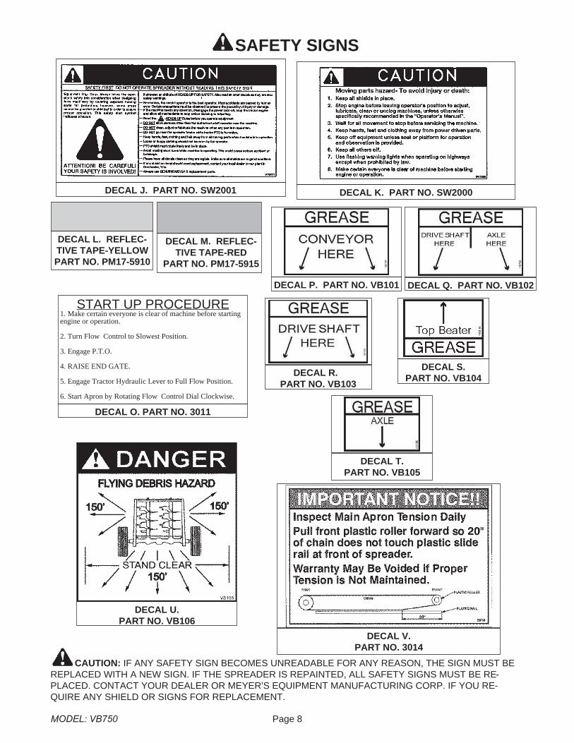
DECAL J. PART NO. SW2001 DECAL K. PART NO. SW2000
DECAL M. REFLEC-TIVE TAPE-RED
PART NO. PM17-5915
DECAL L. REFLEC-TIVE TAPE-YELLOWPART NO. PM17-5910
CAUTION: IF ANY SAFETY SIGN BECOMES UNREADABLE FOR ANY REASON, THE SIGN MUST BEREPLACED WITH A NEW SIGN. IF THE SPREADER IS REPAINTED, ALL SAFETY SIGNS MUST BE RE-PLACED. CONTACT YOUR DEALER OR MEYER’S EQUIPMENT MANUFACTURING CORP. IF YOU RE-QUIRE ANY SHIELD OR SIGNS FOR REPLACEMENT.
SAFETY SIGNS
START UP PROCEDURE1. Make certain everyone is clear of machine before startingengine or operation.
2. Turn Flow Control to Slowest Position.
3. Engage P.T.O.
4. RAISE END GATE.
5. Engage Tractor Hydraulic Lever to Full Flow Position.
6. Start Apron by Rotating Flow Control Dial Clockwise.
DECAL O. PART NO. 3011
DECAL T.PART NO. VB105
DECAL P. PART NO. VB101 DECAL Q. PART NO. VB102
DECAL R.PART NO. VB103
DECAL S.PART NO. VB104
DECAL U.PART NO. VB106
DECAL V.PART NO. 3014

Page 9 MODEL: VB750
MANURE SPREADER SAFETY
CAUTIONTHERE ARE INHERENT HAZARDS ASSOCIATED WITH THE OPERATION OF A MANURE SPREADER.FOR YOUR SAFETY:
� Never Enter Spreader Box While In Operation For Any Reason.
� Only Properly Instructed People Should Operate The Spreader. Do Not Allow Children Or Inexperienced Per-sons To Operate Spreader.
� Keep All Guards And Shields In Place. Moving Parts Can Crush And Dismember.
� Clear The Area Before Equipment Start Up.
� Keep Hands, Feet, And Loose Clothing Away From Moving Parts.
� Do Not Go Near The Spreader Beaters While Machine Is Operating.
� Make Sure The PTO Is Securely Locked To Both The Tractor And Spreader Before Operating The Unit.
� Do Not Operate The PTO At Speeds Higher Than The Manufacturers Recommendations.
� Highway Traffic Is Not To Exceed 20 Mph. The Tires Supplied Are For Farm Use Only And Are Not DesignedFor Use Above This Speed Unless Equipped With High Speed Highway/Offroad Farm Tires.
� Use Adequate Safety Chains When Towing The Spreader.
� The Use Of A Slow moving Vehicle Sign Is Required On All Public Roads Unless Equipped With FlashingHazard Lights. Obey All Applicable Highway Safety Laws And Rules.
� Always Use A Tractor Large Enough To Provide Sufficient Braking Assistance When Towing A LoadedSpreader.
� Use Caution When Traveling Over Uneven Terrain And When Approaching Stops.
� Do Not Load The Spreader Unless It Is Hitched To The Tractor.
� Do Not Unhitch A Loaded Spreader From The Tractor Leaving It Supported By Only The Jack.
� Park Your Spreader On Level Ground And Place Blocks Ahead Of And Behind The Wheels Before Un-hooking From Tractor To Avoid Unexpected Rolling When Separated From The Tractor.
� Do Not Allow Riders on Spreader.
FAILURE TO HEED MAY RESULT IN SERIOUS PERSONAL INJURY OR DEATH
CAUTIONTHERE ARE ADDITIONAL HAZARDS ASSOCIATED WITH THE SERVICE AND MAINTENANCE OF YOURSPREADER.
FOR YOUR SAFETY:
� Inspect When First Delivered And Regularly Thereafter; That All Connections And Bolts Are Tight And SecureBefore Operating.
� Retighten All Wheel Bolts After The First Hour Of Towing. Check Periodically Thereafter. See Maintenance, Wheels.
� Maintain Proper Tire Air Pressure At All Times. See Maintenance Chapter, Tires.
� Never Inflate Beyond Rim Or Tire Manufacturer’s Approved Psi Rating. While Inflating, Stay Out Of The Tra-jectory & Stand Clear Of Tire/Wheel Assembly. A Tire Blow Out Or Rim/Wheel Failure Can Cause Serious In-jury Or Death.
� If The Rim Lock Ring Should Blow Off, It And Other Parts Could Fly Off With Enough Force To Injure Or Kill APerson. Never Stand In The Potential Blow Out Area And Keep Others Away.
� Removing, Replacing And Repairing Industrial Tires And Rims With Lock Rings Can Be Dangerous WithoutProper Tools, Equipment And Training To Perform This Service. It Is Recommended That This Work Be Per-formed Only By A Qualified Tire Repair Shop.

MODEL: VB750 Page 10
Most farm accidents, like industrial, home and high-way accidents, are caused by the failure of someindividuals to observe simple and fundamentalsafety rules or precautions. For this reason farmaccidents, just as other types of accidents, can beprevented by recognizing the causes of accidentsand doing something about them before an acci-dent occurs.
Regardless of the care used in the design and con-struction of farm equipment, there are many pointsthat cannot be completely safe-guarded without in-terfering with accessibility and efficient operation.
A careful operator is the best insurance against anaccident.
The complete observance of one simple rule wouldprevent many thousand serious injuries each year.That rule is “NEVER ATTEMPT TO CLEAN, OIL,OR ADJUST A MACHINE WHILE IN MOTION”.
NATIONAL SAFETY COUNCIL
MANDATORY SAFETY SHUTDOWN PROCEDUREBEFORE unclogging, cleaning, adjusting, lubricating or servicing the unit:
1. Disengage the tractor PTO.
2. Shut off the tractor engine, remove the ignition key and take it with you.
3. Wait for all movement to stop.
4. Remove the Telescoping PTO Drive and ALL power connections from the tractor.
ONLY when you have taken these precautions can you be sure it is safe to proceed. Failure to follow the aboveprocedure could lead to death or serious bodily injury.
BEFORE ATTEMPTING TO OPERATE YOUR NEW SPREADER BE SURE TO READ THIS OWNERS MANUALAND FAMILIARIZE YOURSELF WITH THE MACHINE!! OBSERVE THE PRECAUTIONS IN THIS MANUALFOR SAFE OPERATION OF THIS MACHINE!!
� Always Wear Eye Protection When Operating Or Servicing Spreader.
� Be Sure All Movement Has Stopped, The PTO Is Disconnected, The Tractor Is Shut Off And The Ignition KeyIs Removed Before Servicing The Spreader Or Components.
� Escaping Hydraulic Fluid Under Pressure Can Penetrate The Skin And Cause Serious Injury. Relieve All Pres-sure From The Hydraulic System Before Connecting Or Disconnecting The Lines Or Making Repairs. CheckAll Hoses And Fittings Before Start-up And Periodically During Operation.
� Never Make Any Alterations Or Modifications To This Equipment.
FAILURE TO HEED MAY RESULT IN SERIOUS PERSONAL INJURY OR DEATH
PRE-OPERATION
GENERAL
Read the entire Owners Manual before attempting tooperate this manure spreader. Before attempting anymaintenance or repairs; always be sure all rotatingparts have stopped and that the tractor is shut off, dis-connect the PTO, relieve all hydraulic pressure anddisconnect hydraulic hoses.
WARNINGNEVER OPERATE SPREADER WITH ANY GUARDSOR SHIELDS REMOVED. FAILURE TO HEED MAYRESULT IN SERIOUS PERSONAL INJURY ORDEATH.
.1 Completely lubricate the unit as described in theLUBRICATION Section.
.2 Check and tighten the wheel lug nuts if required.
.3 Check and maintain the tire pressure according tothe manufacturer’s recommendation.
.4 Check the entire unit for loose bolts, damaged orloose hydraulic fittings and hoses or other dam-aged parts.
.5 The tractor half of the PTO drive shaft assemblymust be locked securely to the tractor output shaft.
TRACTOR HITCH AND PTOREQUIREMENTS
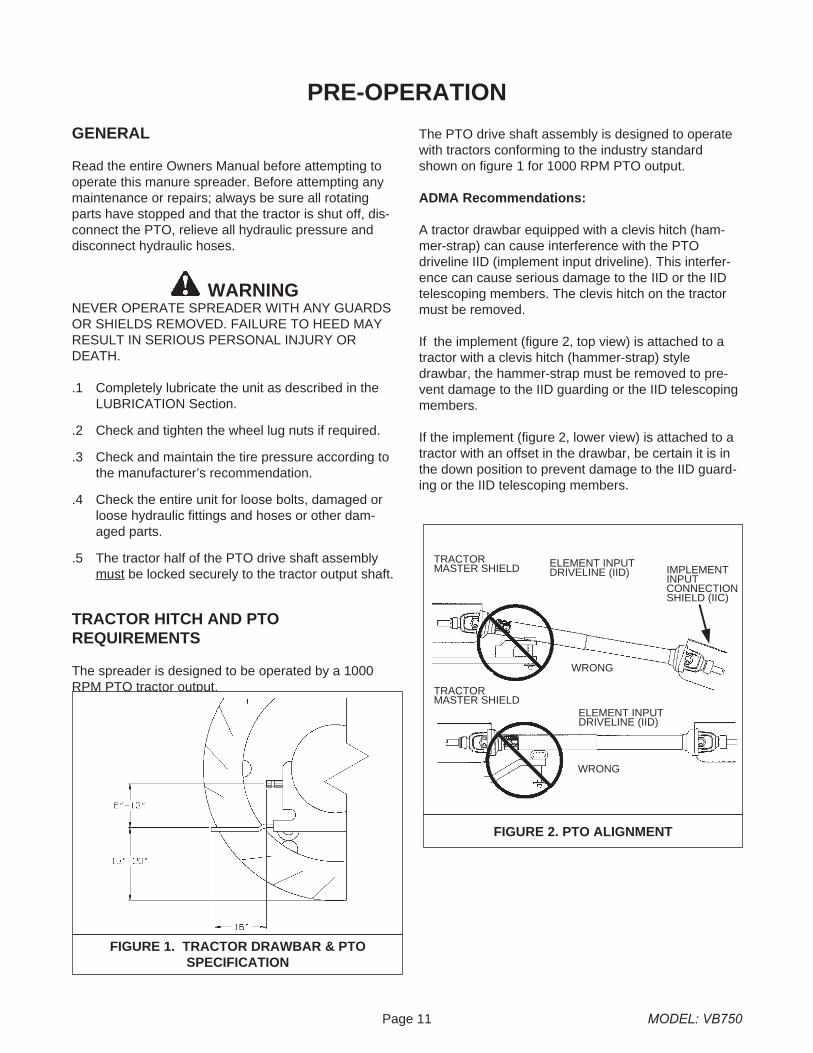
The spreader is designed to be operated by a 1000RPM PTO tractor output.
The PTO drive shaft assembly is designed to operatewith tractors conforming to the industry standardshown on figure 1 for 1000 RPM PTO output.
ADMA Recommendations:
A tractor drawbar equipped with a clevis hitch (ham-mer-strap) can cause interference with the PTOdriveline IID (implement input driveline). This interfer-ence can cause serious damage to the IID or the IIDtelescoping members. The clevis hitch on the tractormust be removed.
If the implement (figure 2, top view) is attached to atractor with a clevis hitch (hammer-strap) styledrawbar, the hammer-strap must be removed to pre-vent damage to the IID guarding or the IID telescopingmembers.
If the implement (figure 2, lower view) is attached to atractor with an offset in the drawbar, be certain it is inthe down position to prevent damage to the IID guard-ing or the IID telescoping members.
Page 11 MODEL: VB750
FIGURE 1. TRACTOR DRAWBAR & PTOSPECIFICATION
FIGURE 2. PTO ALIGNMENT
TRACTORMASTER SHIELD IMPLEMENT
INPUTCONNECTIONSHIELD (IIC)
WRONG
WRONG
TRACTORMASTER SHIELD
ELEMENT INPUTDRIVELINE (IID)
ELEMENT INPUTDRIVELINE (IID)
TRACTOR SIZE REQUIREMENTS
The spreader does not have brakes. Towing thespreader must be done safely. The ASAE (AmericanSociety of Agricultural Engineers) specifies that thetowing vehicle should weigh at least 2/3 as much asthe loaded implement to be reasonably safe towing atspeeds up to 20 mph. This (20 mph) is also the maxi-mum recommended towing speed for the spreader.
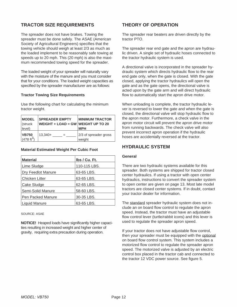
The loaded weight of your spreader will naturally varywith the moisture of the manure and you must considerthat for your conditions. The loaded weight capacities asspecified by the spreader manufacturer are as follows:
Tractor Towing Size Requirements
Use the following chart for calculating the minimumtractor weight.
MODEL(strucklevel)
SPREADER EMPTYWEIGHT + LOAD = GW
MINIMUM TRACTORWEIGHT UP TO 20MPH
VB750(478 ft3)
13,340+ _____ = _____ 2/3 of spreader grossweight
Material Estimated Weight Per Cubic Foot
Material lbs / Cu. Ft.
Lime Sludge 110-115 LBS.
Dry Feedlot Manure 63-65 LBS.
Chicken Litter 63-65 LBS.
Cake Sludge 62-65 LBS.
Semi-Solid Manure 58-60 LBS.
Pen Packed Manure 30-35 LBS.
Liquid Manure 63-65 LBS.
SOURCE: ASAE
NOTICE! Heaped loads have significantly higher capaci-ties resulting in increased weight and higher center ofgravity, requiring extra precaution during operation.
THEORY OF OPERATION
The spreader rear beaters are driven directly by thetractor PTO.
The spreader rear end gate and the apron are hydrau-lic driven. A single set of hydraulic hoses connected tothe tractor hydraulic system is used.
A directional valve is incorporated in the spreader hy-draulic system which directs hydraulic flow to the rearend gate only, when the gate is closed. With the gateclosed, applying the tractor hydraulics will open thegate and as the gate opens, the directional valve isacted upon by the gate arm and will direct hydraulicflow to automatically start the apron drive motor.
When unloading is complete, the tractor hydraulic le-ver is reversed to lower the gate and when the gate isclosed, the directional valve will stop hydraulic flow tothe apron motor. Furthermore, a check valve in theapron motor circuit will prevent the apron drive motorfrom running backwards. The check valve will alsoprevent incorrect apron operation if the hydraulichoses are accidentally reversed at the tractor.
HYDRAULIC SYSTEM
General
There are two hydraulic systems available for thisspreader. Both systems are shipped for tractor closedcenter hydraulics. If using a tractor with open centerhydraulics, instructions to convert the spreader systemto open center are given on page 13. Most late modeltractors are closed center systems. If in doubt, contactyour tractor dealer for information.
The standard spreader hydraulic system does not in-clude an on board flow control to regulate the apronspeed. Instead, the tractor must have an adjustableflow control lever (turtle/rabbit icons) and this lever isused to regulate the spreader apron speed.
If your tractor does not have adjustable flow control,then your spreader must be equipped with the optionalon board flow control system. This system includes amotorized flow control to regulate the spreader apronspeed. The motorized valve is adjusted by an electriccontrol box placed in the tractor cab and connected tothe tractor 12 VDC power source. See figure 5.
MODEL: VB750 Page 12
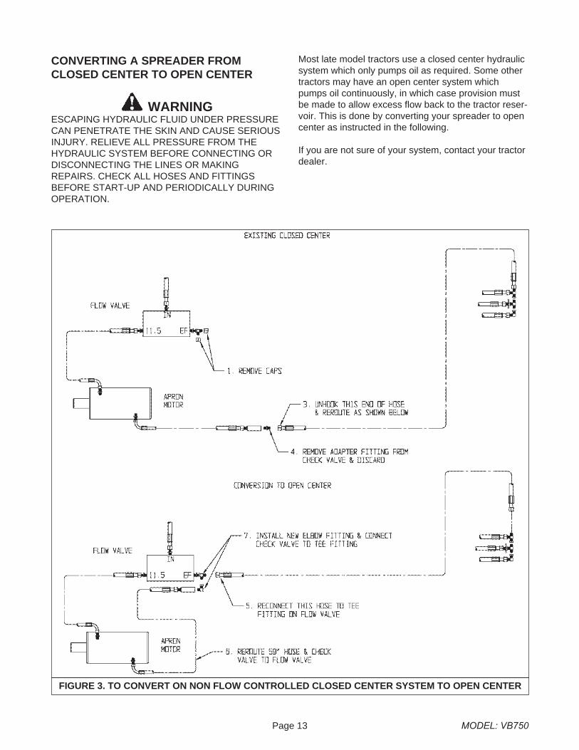
CONVERTING A SPREADER FROMCLOSED CENTER TO OPEN CENTER
WARNINGESCAPING HYDRAULIC FLUID UNDER PRESSURECAN PENETRATE THE SKIN AND CAUSE SERIOUSINJURY. RELIEVE ALL PRESSURE FROM THEHYDRAULIC SYSTEM BEFORE CONNECTING ORDISCONNECTING THE LINES OR MAKINGREPAIRS. CHECK ALL HOSES AND FITTINGSBEFORE START-UP AND PERIODICALLY DURINGOPERATION.
Most late model tractors use a closed center hydraulicsystem which only pumps oil as required. Some othertractors may have an open center system whichpumps oil continuously, in which case provision mustbe made to allow excess flow back to the tractor reser-voir. This is done by converting your spreader to opencenter as instructed in the following.
If you are not sure of your system, contact your tractordealer.
Page 13 MODEL: VB750
FIGURE 3. TO CONVERT ON NON FLOW CONTROLLED CLOSED CENTER SYSTEM TO OPEN CENTER
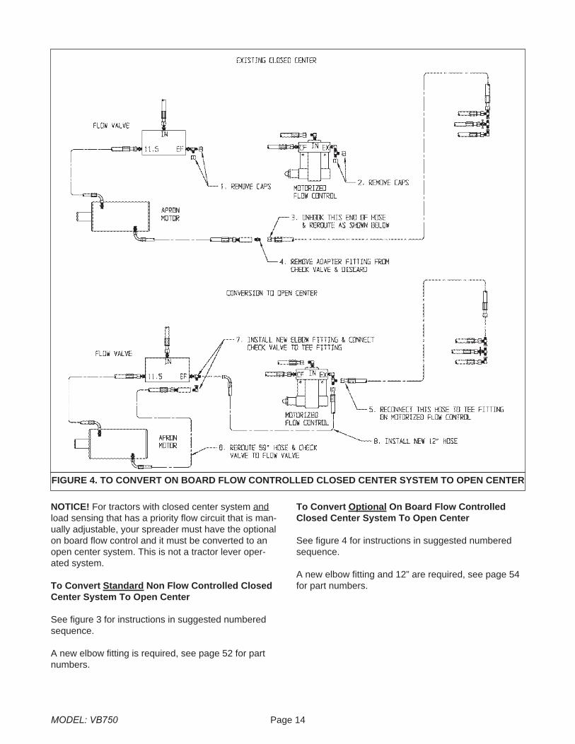
NOTICE! For tractors with closed center system andload sensing that has a priority flow circuit that is man-ually adjustable, your spreader must have the optionalon board flow control and it must be converted to anopen center system. This is not a tractor lever oper-ated system.
To Convert Standard Non Flow Controlled ClosedCenter System To Open Center
See figure 3 for instructions in suggested numberedsequence.
A new elbow fitting is required, see page 52 for partnumbers.
To Convert Optional On Board Flow ControlledClosed Center System To Open Center
See figure 4 for instructions in suggested numberedsequence.
A new elbow fitting and 12” are required, see page 54for part numbers.
MODEL: VB750 Page 14
FIGURE 4. TO CONVERT ON BOARD FLOW CONTROLLED CLOSED CENTER SYSTEM TO OPEN CENTER
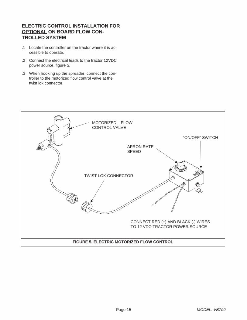
ELECTRIC CONTROL INSTALLATION FOROPTIONAL ON BOARD FLOW CON-TROLLED SYSTEM
.1 Locate the controller on the tractor where it is ac-cessible to operate.
.2 Connect the electrical leads to the tractor 12VDCpower source, figure 5.
.3 When hooking up the spreader, connect the con-troller to the motorized flow control valve at thetwist lok connector.
Page 15 MODEL: VB750
FIGURE 5. ELECTRIC MOTORIZED FLOW CONTROL
MOTORIZED FLOWCONTROL VALVE
APRON RATESPEED
“ON/OFF” SWITCH
TWIST LOK CONNECTOR
CONNECT RED (+) AND BLACK (-) WIRESTO 12 VDC TRACTOR POWER SOURCE
TRANSPORTING
General
Check for traffic constantly. Be sure you can see thatno one is attempting to pass you and that all traffic issufficiently clear from you before making any turns.
WARNINGBE SURE THE SLOW MOVING VEHICLE SIGN ISINSTALLED ON THE REAR OF THE SPREADERFOR TRANSPORTING ON ROADWAYS. KEEP THISSIGN AND ALL REFLECTIVE DECALS CLEAN. FAIL-URE TO HEED MAY RESULT IN SERIOUS PER-SONAL INJURY OR DEATH.
CAUTION:REGULARLY CLEAN OFF THE REFLECTIVE TAPEAT THE REAR AND SIDES OF THE SPREADERWHEN TRANSPORTING IT ON THE HIGHWAY.
WARNINGDO NOT TOW AT SPEEDS GREATER THAN 20MPH. FAILURE TO HEED MAY RESULT IN SERI-OUS PERSONAL INJURY OR DEATH.
Operating speed is dictated by the terrain over whichyou are traveling. Always use caution. Avoid travelingon slopes or hills that are unsafe. Also beware of slip-pery conditions such as traveling over areas previouslyspread with manure. If possible, avoid spreading overareas where manure has been previously applied.
If you will travel on public roadways and it is le-gal to do so, you must know all rules governingsuch operation. This will include lighting andbrake requirements in addition to traffic rules.You may also be required to install a safetychain on the spreader.
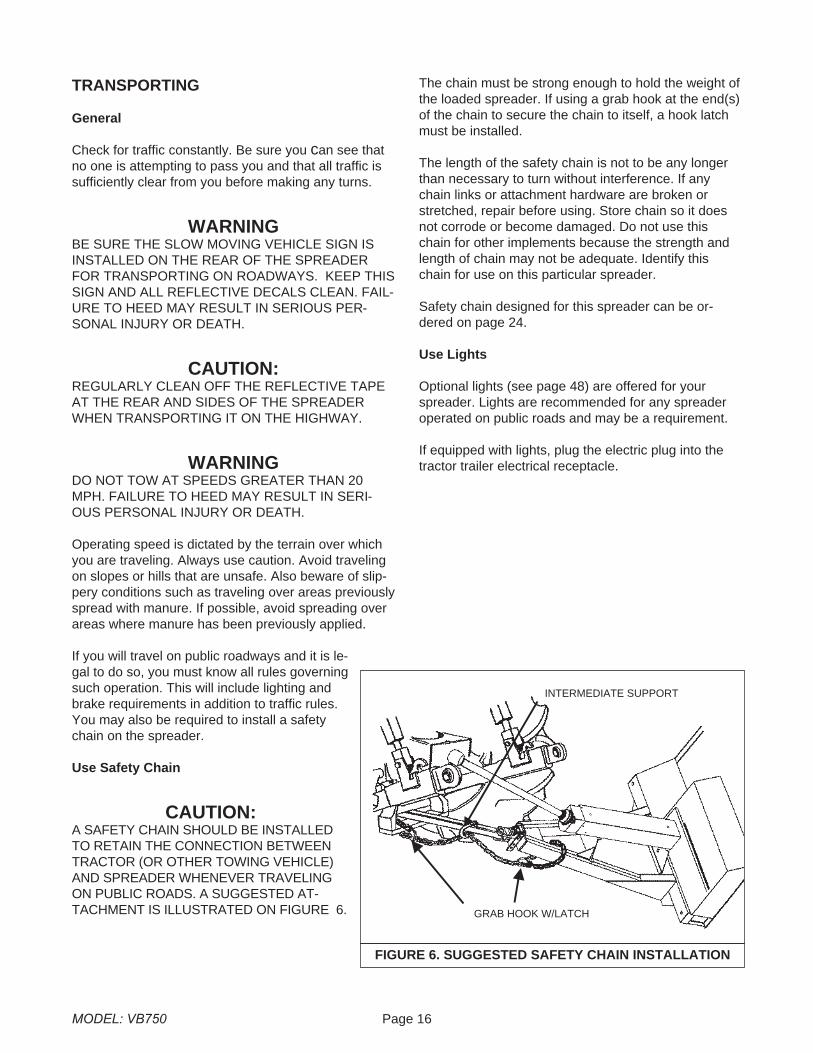
Use Safety Chain
CAUTION:A SAFETY CHAIN SHOULD BE INSTALLEDTO RETAIN THE CONNECTION BETWEENTRACTOR (OR OTHER TOWING VEHICLE)AND SPREADER WHENEVER TRAVELINGON PUBLIC ROADS. A SUGGESTED AT-TACHMENT IS ILLUSTRATED ON FIGURE 6.
The chain must be strong enough to hold the weight ofthe loaded spreader. If using a grab hook at the end(s)of the chain to secure the chain to itself, a hook latchmust be installed.
The length of the safety chain is not to be any longerthan necessary to turn without interference. If anychain links or attachment hardware are broken orstretched, repair before using. Store chain so it doesnot corrode or become damaged. Do not use thischain for other implements because the strength andlength of chain may not be adequate. Identify thischain for use on this particular spreader.
Safety chain designed for this spreader can be or-dered on page 24.
Use Lights
Optional lights (see page 48) are offered for yourspreader. Lights are recommended for any spreaderoperated on public roads and may be a requirement.
If equipped with lights, plug the electric plug into thetractor trailer electrical receptacle.
MODEL: VB750 Page 16
FIGURE 6. SUGGESTED SAFETY CHAIN INSTALLATION
GRAB HOOK W/LATCH
INTERMEDIATE SUPPORT
Page 17 MODEL: VB750
OPERATION
DANGERNEVER ENTER THE SPREADER BOX FOR ANYREASON WITHOUT FIRST DISCONNECTING PTOSHAFT FROM TRACTOR. DO NOT ALLOWOTHERS IN THE BOX. ROTATING BEATER CANDISMEMBER OR KILL.
TRACTOR HOOKUP
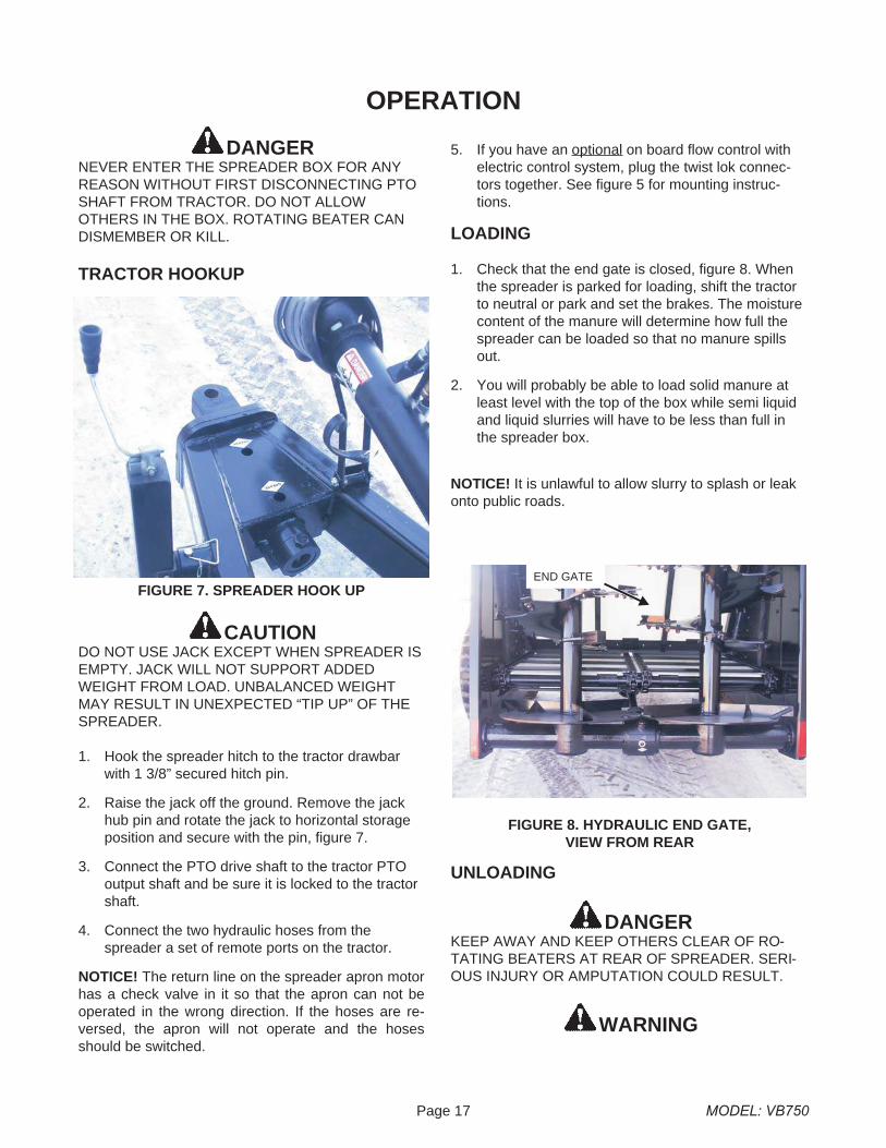
CAUTIONDO NOT USE JACK EXCEPT WHEN SPREADER ISEMPTY. JACK WILL NOT SUPPORT ADDEDWEIGHT FROM LOAD. UNBALANCED WEIGHTMAY RESULT IN UNEXPECTED “TIP UP” OF THESPREADER.
1. Hook the spreader hitch to the tractor drawbarwith 1 3/8” secured hitch pin.
2. Raise the jack off the ground. Remove the jackhub pin and rotate the jack to horizontal storageposition and secure with the pin, figure 7.
3. Connect the PTO drive shaft to the tractor PTOoutput shaft and be sure it is locked to the tractorshaft.
4. Connect the two hydraulic hoses from thespreader a set of remote ports on the tractor.
NOTICE! The return line on the spreader apron motorhas a check valve in it so that the apron can not beoperated in the wrong direction. If the hoses are re-versed, the apron will not operate and the hosesshould be switched.
5. If you have an optional on board flow control withelectric control system, plug the twist lok connec-tors together. See figure 5 for mounting instruc-tions.
LOADING
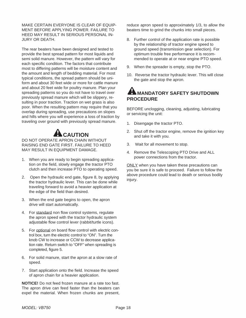
1. Check that the end gate is closed, figure 8. Whenthe spreader is parked for loading, shift the tractorto neutral or park and set the brakes. The moisturecontent of the manure will determine how full thespreader can be loaded so that no manure spillsout.
2. You will probably be able to load solid manure atleast level with the top of the box while semi liquidand liquid slurries will have to be less than full inthe spreader box.
NOTICE! It is unlawful to allow slurry to splash or leakonto public roads.
UNLOADING
DANGERKEEP AWAY AND KEEP OTHERS CLEAR OF RO-TATING BEATERS AT REAR OF SPREADER. SERI-OUS INJURY OR AMPUTATION COULD RESULT.
WARNING
FIGURE 7. SPREADER HOOK UP
FIGURE 8. HYDRAULIC END GATE,VIEW FROM REAR
END GATE
MAKE CERTAIN EVERYONE IS CLEAR OF EQUIP-MENT BEFORE APPLYING POWER. FAILURE TOHEED MAY RESULT IN SERIOUS PERSONAL IN-JURY OR DEATH.
The rear beaters have been designed and tested toprovide the best spread pattern for most liquids andsemi solid manure. However, the pattern will vary foreach specific condition. The factors that contributemost to differing patterns will be moisture content andthe amount and length of bedding material. For mosttypical conditions, the spread pattern should be uni-form and about 30 feet wide or more for cattle manureand about 20 feet wide for poultry manure. Plan yourspreading patterns so you do not have to travel overpreviously spread manure which will be slippery, re-sulting in poor traction. Traction on wet grass is alsopoor. When the resulting pattern may require that youoverlap during spreading, use precautions on slopesand hills where you will experience a loss of traction bytraveling over ground with previously spread manure.
CAUTIONDO NOT OPERATE APRON CHAIN WITHOUTRAISING END GATE FIRST. FAILURE TO HEEDMAY RESULT IN EQUIPMENT DAMAGE.
1. When you are ready to begin spreading applica-tion on the field, slowly engage the tractor PTOclutch and then increase PTO to operating speed.
2. Open the hydraulic end gate, figure 8, by applyingthe tractor hydraulic lever. This can be done whiletraveling forward to avoid a heavier application atthe edge of the field than desired.
3. When the end gate begins to open, the aprondrive will start automatically.
4. For standard non flow control systems, regulatethe apron speed with the tractor hydraulic systemadjustable flow control lever (rabbit/turtle icons).
5. For optional on board flow control with electric con-trol box, turn the electric control to “ON”. Turn theknob CW to increase or CCW to decrease applica-tion rate. Return switch to “OFF” when spreading iscompleted, figure 5.
6. For solid manure, start the apron at a slow rate ofspeed.
7. Start application onto the field. Increase the speedof apron chain for a heavier application.
NOTICE! Do not feed frozen manure at a rate too fast.The apron drive can feed faster than the beaters canexpel the material. When frozen chunks are present,
reduce apron speed to approximately 1/3, to allow thebeaters time to grind the chunks into small pieces.
8. Further control of the application rate is possibleby the relationship of tractor engine speed toground speed (transmission gear selection). Foroptimum trouble free performance it is recom-mended to operate at or near engine PTO speed.
9. When the spreader is empty, stop the PTO.
10. Reverse the tractor hydraulic lever. This will closethe gate and stop the apron.
MANDATORY SAFETY SHUTDOWNPROCEDURE
BEFORE unclogging, cleaning, adjusting, lubricatingor servicing the unit:
1. Disengage the tractor PTO.
2. Shut off the tractor engine, remove the ignition keyand take it with you.
3. Wait for all movement to stop.
4. Remove the Telescoping PTO Drive and ALLpower connections from the tractor.
ONLY when you have taken these precautions canyou be sure it is safe to proceed. Failure to follow theabove procedure could lead to death or serious bodilyinjury.
MODEL: VB750 Page 18
MAINTENANCE, ADJUSTMENTS & LUBRICATION
WARNINGDISCONNECT PTO DRIVE SHAFT AND HYDRAULICHOSES BEFORE CLEANING, ADJUSTING OR SER-VICING THIS MACHINE. FAILURE TO HEED MAY RE-SULT IN SERIOUS PERSONAL INJURY OR DEATH.
WARNINGAPRON STARTS AUTOMATICALLY WHEN GATEOPENS.
WHEEL AND TIRE MAINTENANCE ANDREPAIR
WHEELS: Check periodically. The wheel studs shouldbe torqued to 297 foot pounds.
VB750 TIRE PRESSURE:75 psi, recommended pressure, 77 psi max.
LOCK RING RIM
WARNINGNEVER INFLATE BEYOND RIM OR TIRE MANU-FACTURER’S APPROVED PSI RATING. WHILE IN-FLATING, STAY OUT OF THE TRAJECTORY &STAND CLEAR OF TIRE/WHEEL ASSEMBLY. ATIRE BLOW OUT OR RIM/WHEEL FAILURE CANCAUSE SERIOUS INJURY OR DEATH.
Removing, replacing and repairing industrial tires andrims with lock rings can be dangerous without propertools, equipment and training to perform this service. Itis recommended that this work be performed only by aqualified tire repair shop.
DANGERIF THE LOCK RING SHOULD BLOW OFF, IT ANDOTHER PARTS COULD FLY OFF WITH ENOUGHFORCE TO INJURE OR KILL A PERSON. NEVERSTAND IN THE POTENTIAL BLOW OUT AREA ANDKEEP OTHERS AWAY.
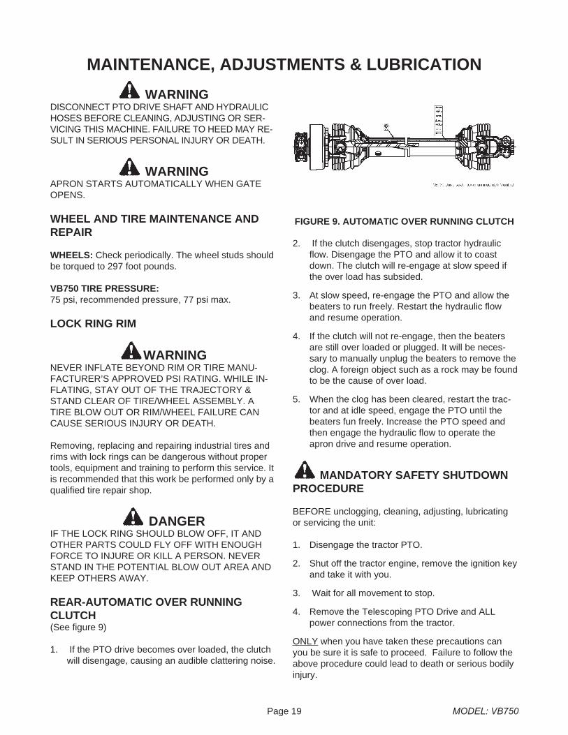
REAR-AUTOMATIC OVER RUNNINGCLUTCH(See figure 9)
1. If the PTO drive becomes over loaded, the clutchwill disengage, causing an audible clattering noise.
2. If the clutch disengages, stop tractor hydraulicflow. Disengage the PTO and allow it to coastdown. The clutch will re-engage at slow speed ifthe over load has subsided.
3. At slow speed, re-engage the PTO and allow thebeaters to run freely. Restart the hydraulic flowand resume operation.
4. If the clutch will not re-engage, then the beatersare still over loaded or plugged. It will be neces-sary to manually unplug the beaters to remove theclog. A foreign object such as a rock may be foundto be the cause of over load.
5. When the clog has been cleared, restart the trac-tor and at idle speed, engage the PTO until thebeaters fun freely. Increase the PTO speed andthen engage the hydraulic flow to operate theapron drive and resume operation.
MANDATORY SAFETY SHUTDOWNPROCEDURE
BEFORE unclogging, cleaning, adjusting, lubricatingor servicing the unit:
1. Disengage the tractor PTO.
2. Shut off the tractor engine, remove the ignition keyand take it with you.
3. Wait for all movement to stop.
4. Remove the Telescoping PTO Drive and ALLpower connections from the tractor.
ONLY when you have taken these precautions canyou be sure it is safe to proceed. Failure to follow theabove procedure could lead to death or serious bodilyinjury.
Page 19 MODEL: VB750
FIGURE 9. AUTOMATIC OVER RUNNING CLUTCH
ADJUSTMENTS
Apron Chain
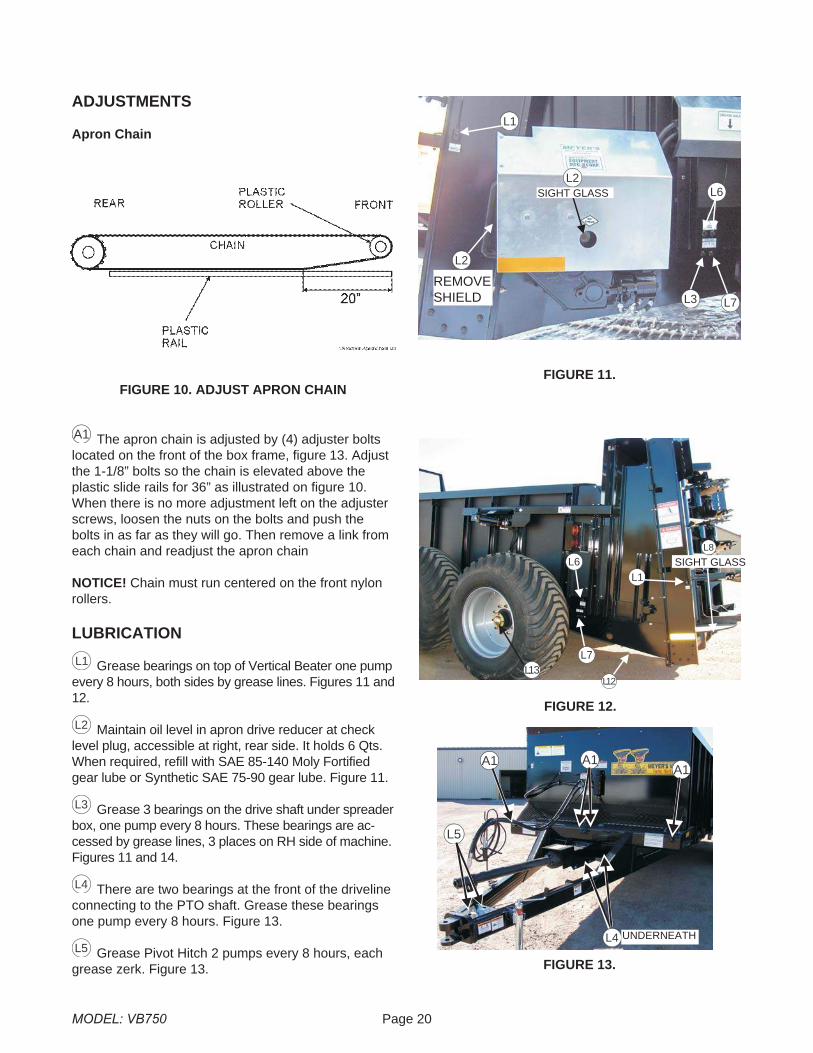
The apron chain is adjusted by (4) adjuster boltslocated on the front of the box frame, figure 13. Adjustthe 1-1/8” bolts so the chain is elevated above theplastic slide rails for 36” as illustrated on figure 10.When there is no more adjustment left on the adjusterscrews, loosen the nuts on the bolts and push thebolts in as far as they will go. Then remove a link fromeach chain and readjust the apron chain
NOTICE! Chain must run centered on the front nylonrollers.
LUBRICATION
Grease bearings on top of Vertical Beater one pumpevery 8 hours, both sides by grease lines. Figures 11 and12.
Maintain oil level in apron drive reducer at checklevel plug, accessible at right, rear side. It holds 6 Qts.When required, refill with SAE 85-140 Moly Fortifiedgear lube or Synthetic SAE 75-90 gear lube. Figure 11.
Grease 3 bearings on the drive shaft under spreaderbox, one pump every 8 hours. These bearings are ac-cessed by grease lines, 3 places on RH side of machine.Figures 11 and 14.
There are two bearings at the front of the drivelineconnecting to the PTO shaft. Grease these bearingsone pump every 8 hours. Figure 13.
Grease Pivot Hitch 2 pumps every 8 hours, eachgrease zerk. Figure 13.
MODEL: VB750 Page 20
FIGURE 10. ADJUST APRON CHAINFIGURE 11.
L1
L6
L7
L2
SIGHT GLASS
REMOVESHIELD L3
L2
FIGURE 12.
L6L1
L7
L8
SIGHT GLASS
L12L13
FIGURE 13.
UNDERNEATHL4
A1A1A1
L5
A1
L1
L2
L3
L4
L5
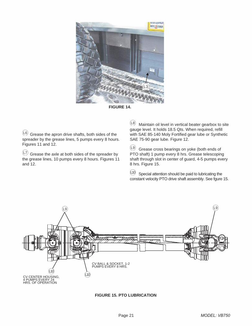
Grease the apron drive shafts, both sides of thespreader by the grease lines, 5 pumps every 8 hours.Figures 11 and 12.
Grease the axle at both sides of the spreader bythe grease lines, 10 pumps every 8 hours. Figures 11and 12.
Maintain oil level in vertical beater gearbox to sitegauge level. It holds 18.5 Qts. When required, refillwith SAE 85-140 Moly Fortified gear lube or SyntheticSAE 75-90 gear lube. Figure 12.
Grease cross bearings on yoke (both ends ofPTO shaft) 1 pump every 8 hrs. Grease telescopingshaft through slot in center of guard, 4-5 pumps every8 hrs. Figure 15.
Special attention should be paid to lubricating theconstant velocity PTO drive shaft assembly. See fgure 15.
Page 21 MODEL: VB750
FIGURE 14.
L3
L7
L8
L9
L5
FIGURE 15. PTO LUBRICATION
L10
L9 L9
L10CV CENTER HOUSING,4 PUMPS EVERY 24HRS. OF OPERATION
CV BALL & SOCKET, 1-2PUMPS EVERY 8 HRS.
L6
L10
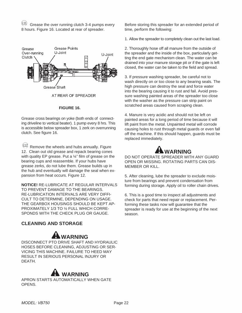
Grease the over running clutch 3-4 pumps every8 hours. Figure 16. Located at rear of spreader.
Grease cross bearings on yoke (both ends of connect-ing driveline to vertical beater). 1 pump every 8 hrs. Thisis accessible below spreader box, 1 zerk on overrunningclutch. See figure 16.
Remove the wheels and hubs annually. Figure12. Clean out old grease and repack bearing coneswith quality EP grease. Put a ¼” film of grease on thebearing cups and reassemble. If your hubs havegrease zerks, do not lube them. Grease builds up inthe hub and eventually will damage the seal when ex-pansion from heat occurs. Figure 12.
NOTICE! RE-LUBRICATE AT REGULAR INTERVALSTO PREVENT DAMAGE TO THE BEARINGS.RE-LUBRICATION INTERVALS ARE VERY DIFFI-CULT TO DETERMINE, DEPENDING ON USAGE.THE GEARBOX HOUSINGS SHOULD BE KEPT AP-PROXIMATELY 1/3 TO ½ FULL WHICH CORRE-SPONDS WITH THE CHECK PLUG OR GAUGE.
CLEANING AND STORAGE
WARNINGDISCONNECT PTO DRIVE SHAFT AND HYDRAULICHOSES BEFORE CLEANING, ADJUSTING OR SER-VICING THIS MACHINE. FAILURE TO HEED MAYRESULT IN SERIOUS PERSONAL INJURY ORDEATH.
WARNINGAPRON STARTS AUTOMATICALLY WHEN GATEOPENS.
Before storing this spreader for an extended period oftime, perform the following:
1. Allow the spreader to completely clean out the last load.
2. Thoroughly hose off all manure from the outside ofthe spreader and the inside of the box, particularly get-ting the end gate mechanism clean. The water can bedrained into your manure storage pit or if the gate is leftclosed, the water can be taken to the field and spread.
3. If pressure washing spreader, be careful not towash directly on or too close to any bearing seals. Thehigh pressure can destroy the seal and force waterinto the bearing causing it to rust and fail. Avoid pres-sure washing painted areas of the spreader too closewith the washer as the pressure can strip paint onscratched areas caused from scraping clean.
4. Manure is very acidic and should not be left onpainted areas for a long period of time because it willlift paint from the metal. Unpainted metal will corrodecausing holes to rust through metal guards or even falloff the machine. If this should happen, guards must bereplaced immediately.
WARNINGDO NOT OPERATE SPREADER WITH ANY GUARDOPEN OR MISSING. ROTATING PARTS CAN DIS-MEMBER OR KILL.
5. After cleaning, lube the spreader to exclude mois-ture from bearings and prevent condensation fromforming during storage. Apply oil to roller chain drives.
6. This is a good time to inspect all adjustments andcheck for parts that need repair or replacement. Per-forming these tasks now will guarantee that thespreader is ready for use at the beginning of the nextseason.
MODEL: VB750 Page 22
FIGURE 16.
L12
L11

Page 23 MODEL: VB750
This Page Intentionally Blank.
REPAIR PARTS
MODEL: VB750 Page 24
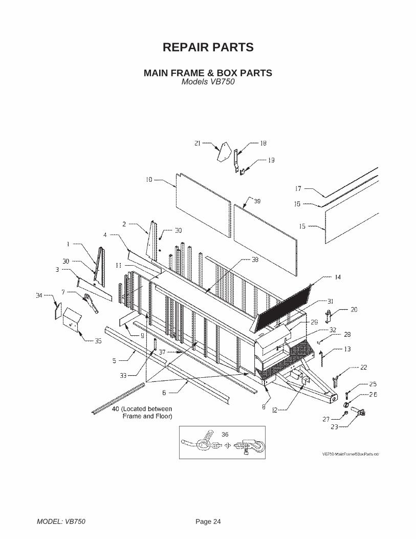
MAIN FRAME & BOX PARTSModels VB750
36

Page 25 MODEL: VB750
KEY PART NO. QTY DESCRIPTION1 VB-0001-09 1 VB-Bracket-RH2 VB-0001-09 1 VB-Bracket-LH3 VB-0004-09 1 VB Bottom Bracket-RH4 VB-0004-09 1 VB-Bottom Bracket-LH5 VB-00022 1 Hose Guard - Rear 1/26 VB-00023 1 Hose Guard - Front 1/27 VB-00016 1 Gearbox Torque Arm8 VB-00026 1 Frame, Main9 VB-00132 1 Belt Deflector10 E00010-11-R 2 Left and Right Rear Side Panel 46" x 101"11 E00019-550/700 1 Floor Complete, 78”x225"12 VB-00129-2-08 1 Shield, Front Drive Shaft w/ Hinge13 E00026 1 Hydraulic Hose Support14 VB-00024 1 Front Splash Pan/Rock Guard15 E20028 1 Front Gate Insert 1/4” x 39-3/4” x 81” Poly16 E00005-09 1 Belt, Bottom Front Gate (79.5")17 E00003 1 Bar, Bottom Front Gate18 E21648 1 SMV Spade Mounting19 E21649 1 SMV Socket Mounting20 E21650 1 Manual Holder w/ Decal21 PM10-11-05 1 SMV Sign22 E21658 1 PTO Stand w/Rubber Strap23 E21659-11 1 Inner Hitch Assembly2425 E21661 1 HHCS, 3/4-10 x 5, GR826 E21662-11 1 Collar27 E21663 1 Nut, 3/4-10, Nylon Lock28 1 Serial Number Plate29 E00303-00 1 Shield, Front30 VB-00025 4 Spacer31 E20942 2 Hinge, Shield32 E00016 1 Lock Assy33 E00007 2 Bar, Axle Retainer34 VB-00131 1 VB Back Gear Box Guard35 VB-00130 1 VB Top - Front Gearbox Guard36 1 Safety Chain, Towing, 40000 lb., Optional37 VB-00208 4 Apron Slide Rails, 208”38 E21664 2 Poly Floor Chain Spacer, 211”39 E00010-11-F 2 Left and Right Front Side Panel 46" x 101"40 3600-VB750-10 3 Floor Hold Down
MAIN FRAME & BOX PARTSModels VB750
MODEL: VB750 Page 26
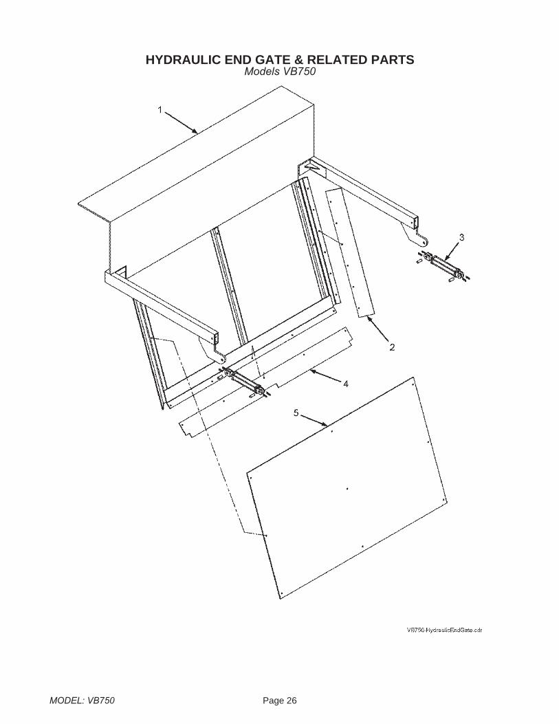
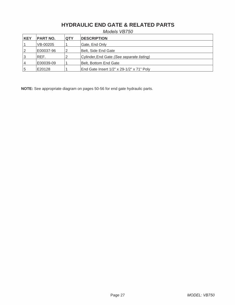
HYDRAULIC END GATE & RELATED PARTSModels VB750
Page 27 MODEL: VB750
KEY PART NO. QTY DESCRIPTION
1 VB-00205 1 Gate, End Only
2 E00037-96 2 Belt, Side End Gate
3 REF. 2 Cylinder,End Gate (See separate listing)
4 E00039-09 1 Belt, Bottom End Gate
5 E20128 1 End Gate Insert 1/2” x 29-1/2” x 71” Poly
NOTE: See appropriate diagram on pages 50-56 for end gate hydraulic parts.
HYDRAULIC END GATE & RELATED PARTSModels VB750
MODEL: VB750 Page 28
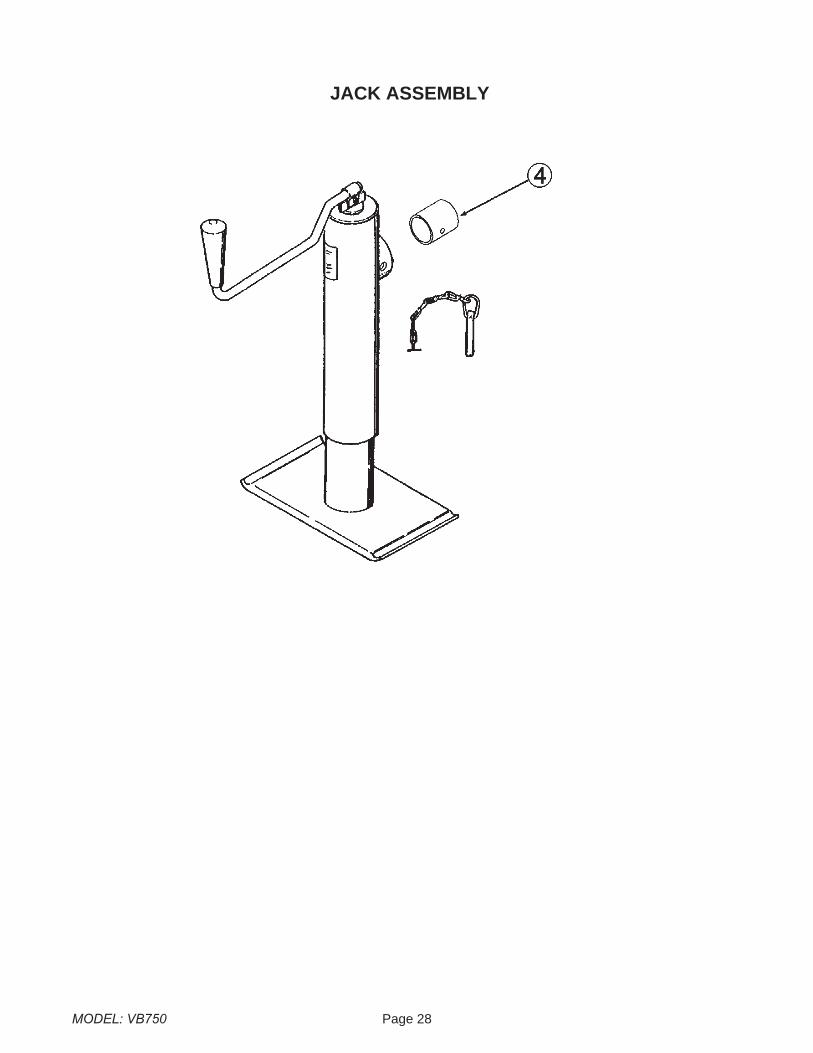
JACK ASSEMBLY

Page 29 MODEL: VB750
KEY PART NO. QTY DESCRIPTION
E00053 1 Jack Assembly
4 E00057 1 Weld on Mount
E20228
JACK ASSEMBLY
MODEL: VB750 Page 30
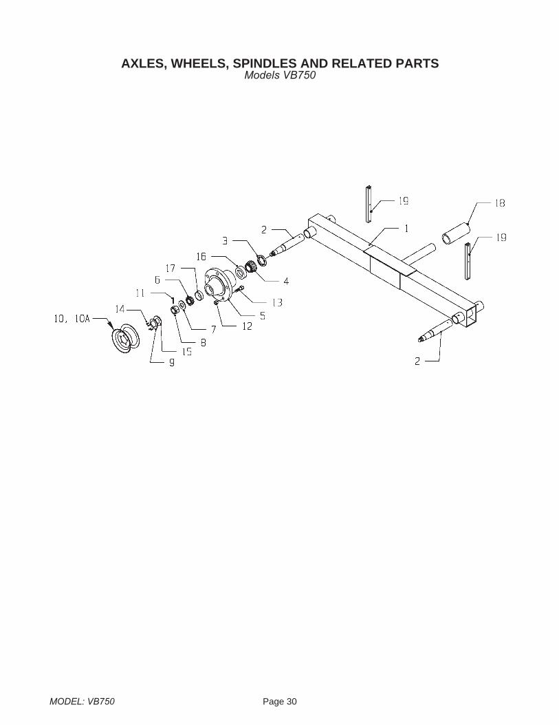
AXLES, WHEELS, SPINDLES AND RELATED PARTSModels VB750
Page 31 MODEL: VB750
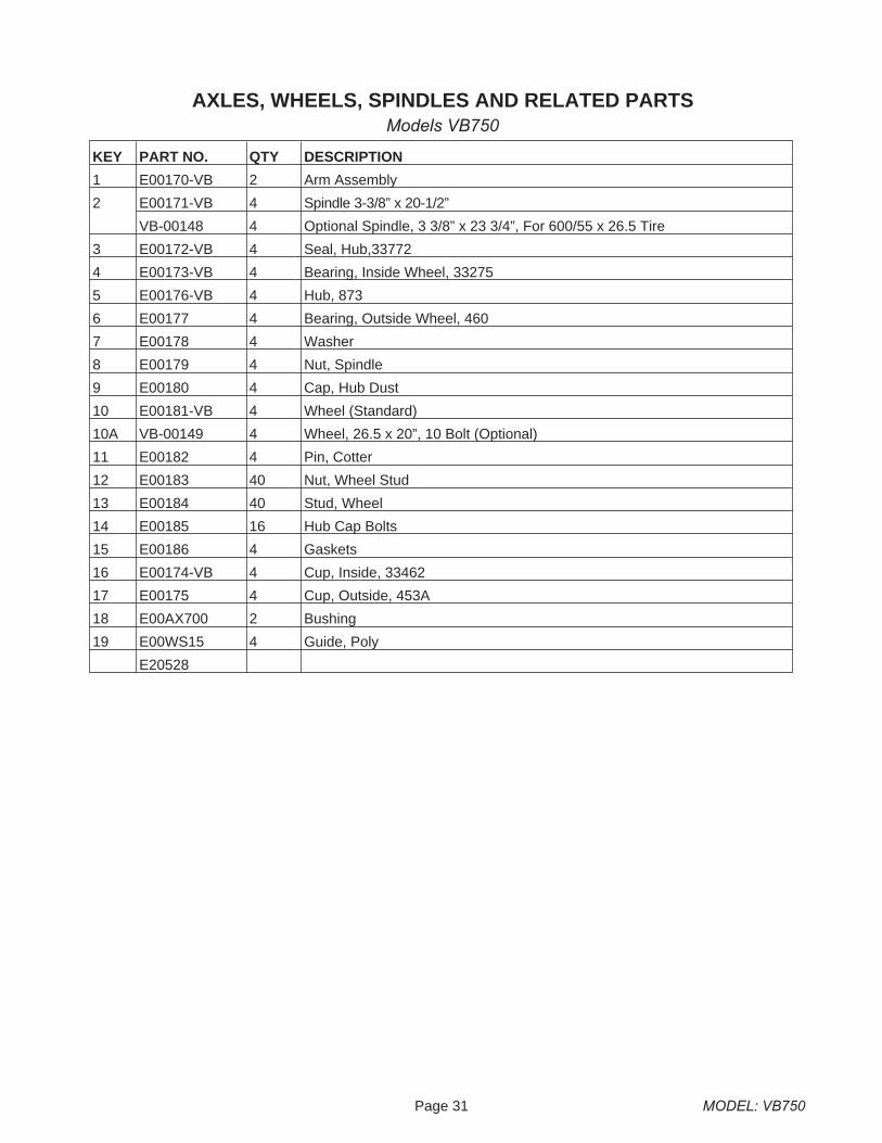
AXLES, WHEELS, SPINDLES AND RELATED PARTSModels VB750
KEY PART NO. QTY DESCRIPTION
1 E00170-VB 2 Arm Assembly
2 E00171-VB 4 Spindle 3-3/8” x 20-1/2”
VB-00148 4 Optional Spindle, 3 3/8” x 23 3/4”, For 600/55 x 26.5 Tire
3 E00172-VB 4 Seal, Hub,33772
4 E00173-VB 4 Bearing, Inside Wheel, 33275
5 E00176-VB 4 Hub, 873
6 E00177 4 Bearing, Outside Wheel, 460
7 E00178 4 Washer
8 E00179 4 Nut, Spindle
9 E00180 4 Cap, Hub Dust
10 E00181-VB 4 Wheel (Standard)
10A VB-00149 4 Wheel, 26.5 x 20”, 10 Bolt (Optional)
11 E00182 4 Pin, Cotter
12 E00183 40 Nut, Wheel Stud
13 E00184 40 Stud, Wheel
14 E00185 16 Hub Cap Bolts
15 E00186 4 Gaskets
16 E00174-VB 4 Cup, Inside, 33462
17 E00175 4 Cup, Outside, 453A
18 E00AX700 2 Bushing
19 E00WS15 4 Guide, Poly
E20528
MODEL: VB750 Page 32
1 3/4” DRIVE TRAINModels VB750
Page 33 MODEL: VB750
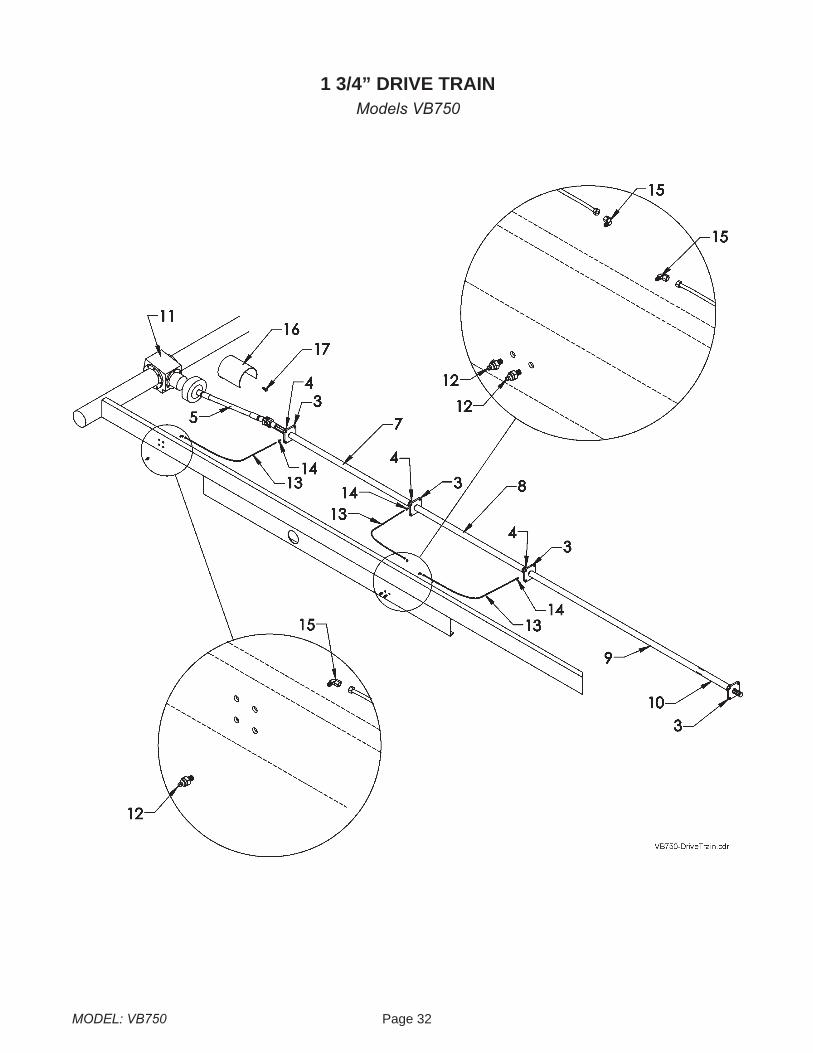
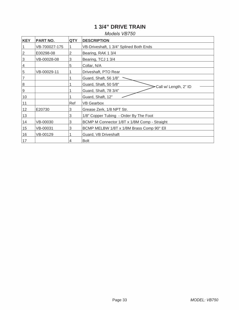
KEY PART NO. QTY DESCRIPTION
1 VB-700027-175 1 VB-Driveshaft, 1 3/4” Splined Both Ends
2 E00298-08 2 Bearing, RAK 1 3/4
3 VB-00028-08 3 Bearing, TCJ 1 3/4
4 5 Collar, N/A
5 VB-00029-11 1 Driveshaft, PTO Rear
7 1 Guard, Shaft, 56 1/8”
8 1 Guard, Shaft, 50 5/8”
9 1 Guard, Shaft, 78 3/4”
10 1 Guard, Shaft, 12”
11 Ref VB Gearbox
12 E20730 3 Grease Zerk, 1/8 NPT Str.
13 3 1/8” Copper Tubing - Order By The Foot
14 VB-00030 3 BCMP M Connector 1/8T x 1/8M Comp - Straight
15 VB-00031 3 BCMP MELBW 1/8T x 1/8M Brass Comp 90° Ell
16 VB-00129 1 Guard, VB Driveshaft
17 4 Bolt
1 3/4” DRIVE TRAINModels VB750
Call w/ Length, 2” ID
MODEL: VB750 Page 34
APRON & RELATED PARTSFOR STANDARD 67P11 CHAIN
Models VB750
Page 35 MODEL: VB750
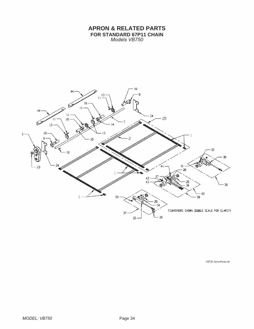
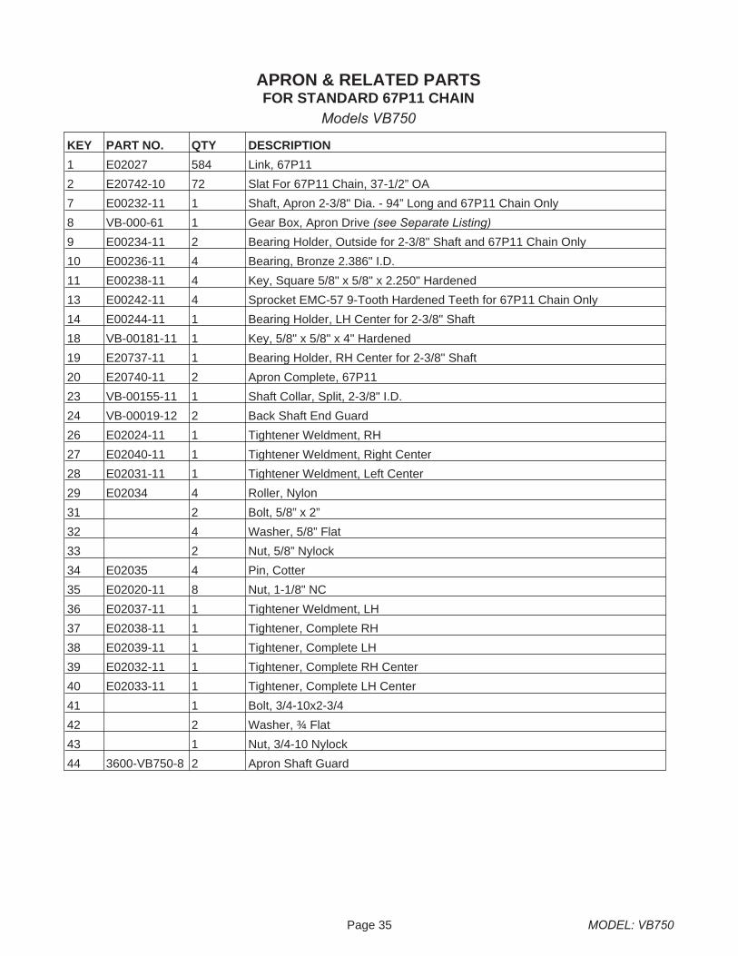
KEY PART NO. QTY DESCRIPTION
1 E02027 584 Link, 67P11
2 E20742-10 72 Slat For 67P11 Chain, 37-1/2” OA
7 E00232-11 1 Shaft, Apron 2-3/8" Dia. - 94” Long and 67P11 Chain Only
8 VB-000-61 1 Gear Box, Apron Drive (see Separate Listing)
9 E00234-11 2 Bearing Holder, Outside for 2-3/8" Shaft and 67P11 Chain Only
10 E00236-11 4 Bearing, Bronze 2.386" I.D.
11 E00238-11 4 Key, Square 5/8" x 5/8" x 2.250" Hardened
13 E00242-11 4 Sprocket EMC-57 9-Tooth Hardened Teeth for 67P11 Chain Only
14 E00244-11 1 Bearing Holder, LH Center for 2-3/8" Shaft
18 VB-00181-11 1 Key, 5/8" x 5/8" x 4" Hardened
19 E20737-11 1 Bearing Holder, RH Center for 2-3/8" Shaft
20 E20740-11 2 Apron Complete, 67P11
23 VB-00155-11 1 Shaft Collar, Split, 2-3/8" I.D.
24 VB-00019-12 2 Back Shaft End Guard
26 E02024-11 1 Tightener Weldment, RH
27 E02040-11 1 Tightener Weldment, Right Center
28 E02031-11 1 Tightener Weldment, Left Center
29 E02034 4 Roller, Nylon
31 2 Bolt, 5/8” x 2”
32 4 Washer, 5/8” Flat
33 2 Nut, 5/8” Nylock
34 E02035 4 Pin, Cotter
35 E02020-11 8 Nut, 1-1/8" NC
36 E02037-11 1 Tightener Weldment, LH
37 E02038-11 1 Tightener, Complete RH
38 E02039-11 1 Tightener, Complete LH
39 E02032-11 1 Tightener, Complete RH Center
40 E02033-11 1 Tightener, Complete LH Center
41 1 Bolt, 3/4-10x2-3/4
42 2 Washer, ¾ Flat
43 1 Nut, 3/4-10 Nylock
44 3600-VB750-8 2 Apron Shaft Guard
APRON & RELATED PARTSFOR STANDARD 67P11 CHAIN
Models VB750
MODEL: VB750 Page 36
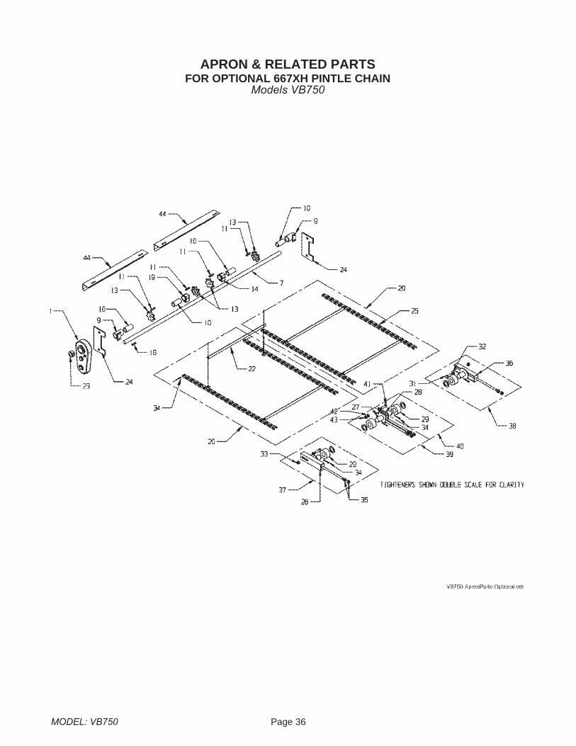
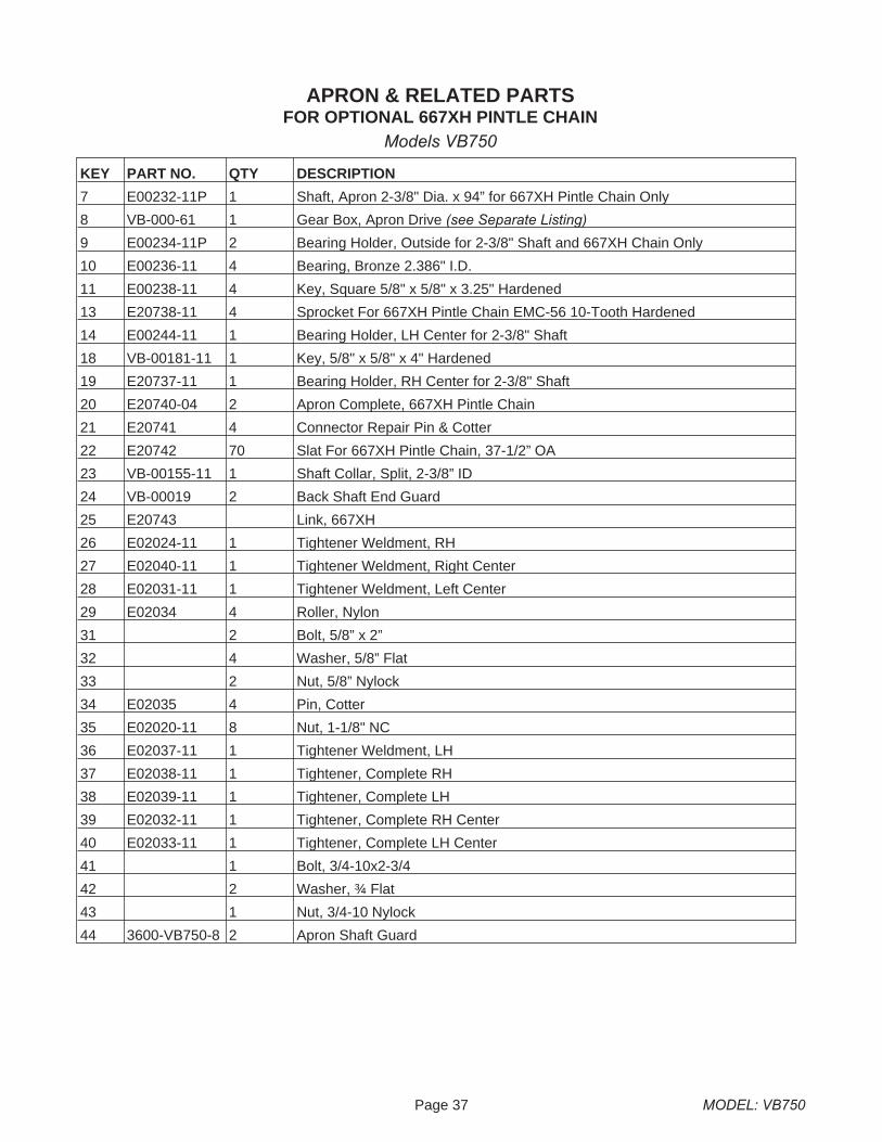
APRON & RELATED PARTSFOR OPTIONAL 667XH PINTLE CHAIN
Models VB750
Page 37 MODEL: VB750
KEY PART NO. QTY DESCRIPTION
7 E00232-11P 1 Shaft, Apron 2-3/8" Dia. x 94” for 667XH Pintle Chain Only
8 VB-000-61 1 Gear Box, Apron Drive (see Separate Listing)
9 E00234-11P 2 Bearing Holder, Outside for 2-3/8" Shaft and 667XH Chain Only
10 E00236-11 4 Bearing, Bronze 2.386" I.D.
11 E00238-11 4 Key, Square 5/8" x 5/8" x 3.25" Hardened
13 E20738-11 4 Sprocket For 667XH Pintle Chain EMC-56 10-Tooth Hardened
14 E00244-11 1 Bearing Holder, LH Center for 2-3/8" Shaft
18 VB-00181-11 1 Key, 5/8" x 5/8" x 4" Hardened
19 E20737-11 1 Bearing Holder, RH Center for 2-3/8" Shaft
20 E20740-04 2 Apron Complete, 667XH Pintle Chain
21 E20741 4 Connector Repair Pin & Cotter
22 E20742 70 Slat For 667XH Pintle Chain, 37-1/2” OA
23 VB-00155-11 1 Shaft Collar, Split, 2-3/8” ID
24 VB-00019 2 Back Shaft End Guard
25 E20743 Link, 667XH
26 E02024-11 1 Tightener Weldment, RH
27 E02040-11 1 Tightener Weldment, Right Center
28 E02031-11 1 Tightener Weldment, Left Center
29 E02034 4 Roller, Nylon
31 2 Bolt, 5/8” x 2”
32 4 Washer, 5/8” Flat
33 2 Nut, 5/8” Nylock
34 E02035 4 Pin, Cotter
35 E02020-11 8 Nut, 1-1/8" NC
36 E02037-11 1 Tightener Weldment, LH
37 E02038-11 1 Tightener, Complete RH
38 E02039-11 1 Tightener, Complete LH
39 E02032-11 1 Tightener, Complete RH Center
40 E02033-11 1 Tightener, Complete LH Center
41 1 Bolt, 3/4-10x2-3/4
42 2 Washer, ¾ Flat
43 1 Nut, 3/4-10 Nylock
44 3600-VB750-8 2 Apron Shaft Guard
APRON & RELATED PARTSFOR OPTIONAL 667XH PINTLE CHAIN
Models VB750
MODEL: VB750 Page 38
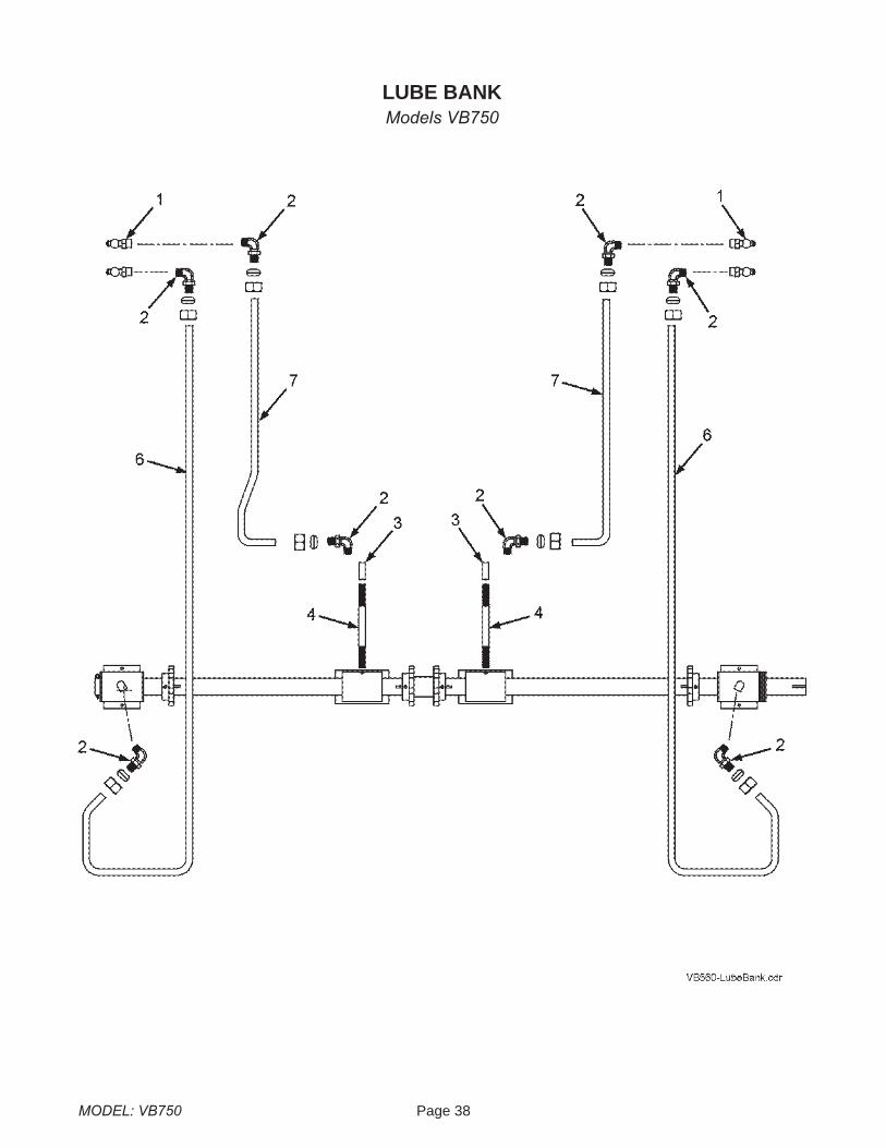
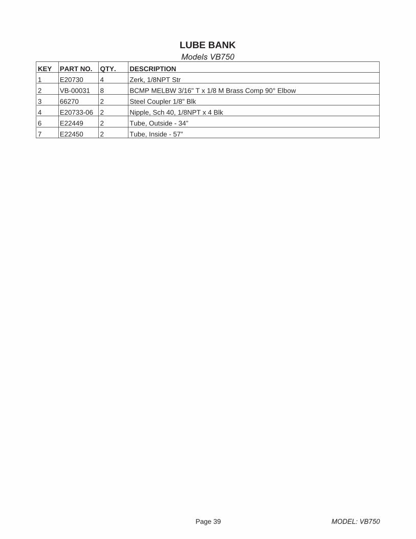
LUBE BANKModels VB750
Page 39 MODEL: VB750
KEY PART NO. QTY. DESCRIPTION
1 E20730 4 Zerk, 1/8NPT Str
2 VB-00031 8 BCMP MELBW 3/16" T x 1/8 M Brass Comp 90° Elbow
3 66270 2 Steel Coupler 1/8" Blk
4 E20733-06 2 Nipple, Sch 40, 1/8NPT x 4 Blk
6 E22449 2 Tube, Outside - 34”
7 E22450 2 Tube, Inside - 57”
LUBE BANKModels VB750
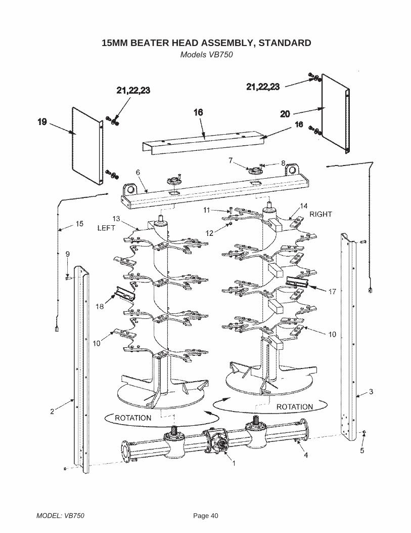
MODEL: VB750 Page 40
15MM BEATER HEAD ASSEMBLY, STANDARDModels VB750

Page 41 MODEL: VB750
KEY PART NO. QTY. DESCRIPTION
1 VB-00073 1 Gear Box SRT12 (see separate parts listing) 10760
2 VB-00074 1 Right Panel 14152
3 VB-00075 1 Left Panel 14153
4 VB-00076 16 Bolt, Hex-Hd M14x45 3489
5 VB-00077 16 Nut M14-8G 1799
6 VB-00078 1 Cross Bar 14247
7 VB-00079 2 UCFC 208 Ø40 Bearing 9905
8 VB-00080 8 Bolt, Hex-Hd M14x40 3311
9 VB-00081 4 Bolt, Hex-Hd M18x45 9156
10 VB-00144 56 Knife, 15mm Thick 10796
11 VB-00145-09 112 Bolt, Hex-Hd M16x50x1.5 10833
12 VB-00086-09 112 Nut M16 10834
13 VB-00146 1 left Beater, 15mm Thick 14119
14 VB-00147 1 Right Beater, 15mm Thick 14118
15 VB-00089 1 Lubrication Kit 9878
16 VB-00150 1 Guard 14246
17 VB-00083 28 Optional Formed Forged Blade 14626
18 VB-00082 28 Optional Formed Forged Blade 14627
19 VB-750-13-R 1 RH Rock Wing
20 VB-750-13-L 1 LH Rock Wing
21 4 Bolt, 3/8-16x1-1/4 Gr5
22 4 Flat Washer, 3/8
23 4 Nut, 3/8-16
15 MM BEATER HEAD ASSEMBLY, STANDARDModels VB750
MODEL: VB750 Page 42
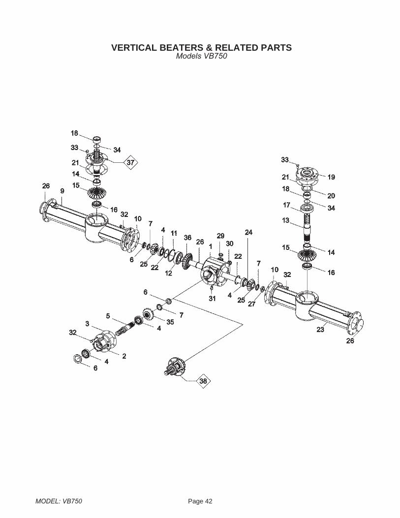
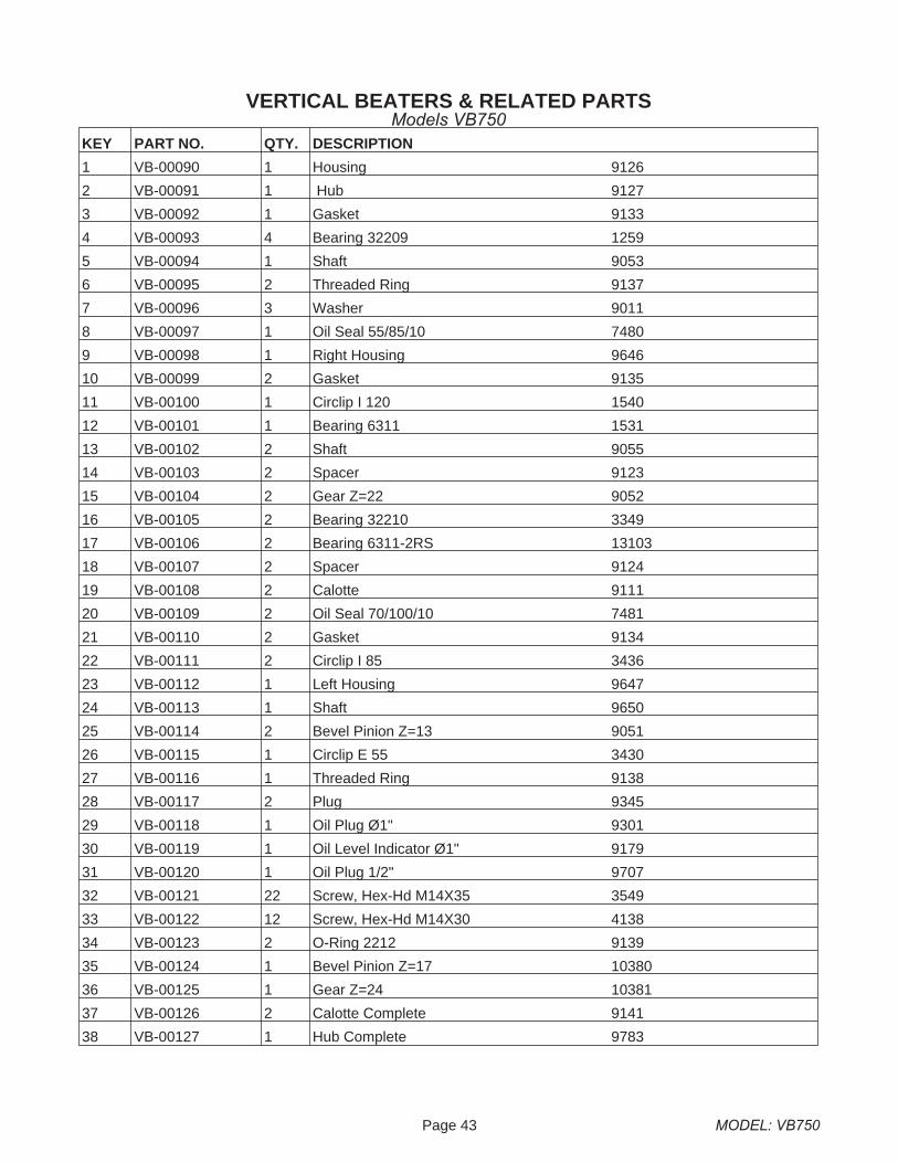
VERTICAL BEATERS & RELATED PARTSModels VB750
Page 43 MODEL: VB750
KEY PART NO. QTY. DESCRIPTION
1 VB-00090 1 Housing 9126
2 VB-00091 1 Hub 9127
3 VB-00092 1 Gasket 9133
4 VB-00093 4 Bearing 32209 1259
5 VB-00094 1 Shaft 9053
6 VB-00095 2 Threaded Ring 9137
7 VB-00096 3 Washer 9011
8 VB-00097 1 Oil Seal 55/85/10 7480
9 VB-00098 1 Right Housing 9646
10 VB-00099 2 Gasket 9135
11 VB-00100 1 Circlip I 120 1540
12 VB-00101 1 Bearing 6311 1531
13 VB-00102 2 Shaft 9055
14 VB-00103 2 Spacer 9123
15 VB-00104 2 Gear Z=22 9052
16 VB-00105 2 Bearing 32210 3349
17 VB-00106 2 Bearing 6311-2RS 13103
18 VB-00107 2 Spacer 9124
19 VB-00108 2 Calotte 9111
20 VB-00109 2 Oil Seal 70/100/10 7481
21 VB-00110 2 Gasket 9134
22 VB-00111 2 Circlip I 85 3436
23 VB-00112 1 Left Housing 9647
24 VB-00113 1 Shaft 9650
25 VB-00114 2 Bevel Pinion Z=13 9051
26 VB-00115 1 Circlip E 55 3430
27 VB-00116 1 Threaded Ring 9138
28 VB-00117 2 Plug 9345
29 VB-00118 1 Oil Plug Ø1" 9301
30 VB-00119 1 Oil Level Indicator Ø1" 9179
31 VB-00120 1 Oil Plug 1/2" 9707
32 VB-00121 22 Screw, Hex-Hd M14X35 3549
33 VB-00122 12 Screw, Hex-Hd M14X30 4138
34 VB-00123 2 O-Ring 2212 9139
35 VB-00124 1 Bevel Pinion Z=17 10380
36 VB-00125 1 Gear Z=24 10381
37 VB-00126 2 Calotte Complete 9141
38 VB-00127 1 Hub Complete 9783
VERTICAL BEATERS & RELATED PARTSModels VB750
MODEL: VB750 Page 44
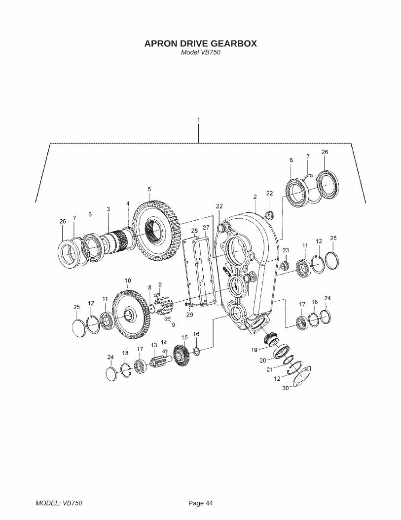
APRON DRIVE GEARBOXModel VB750
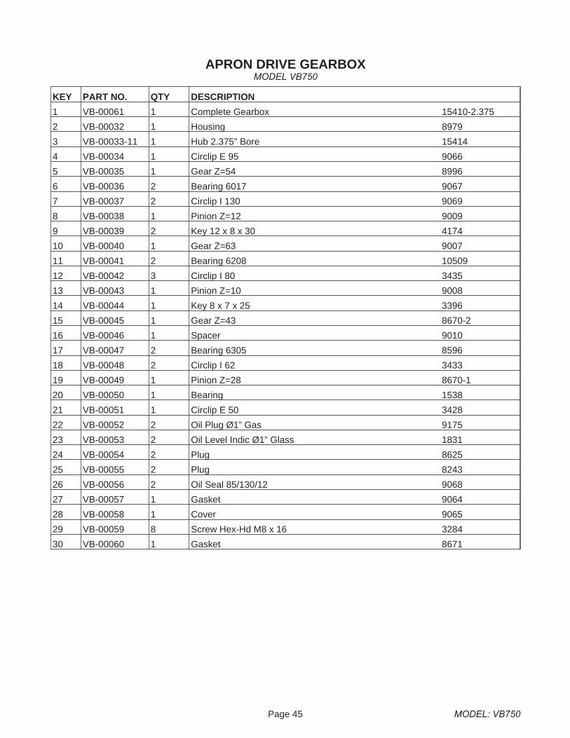
Page 45 MODEL: VB750
KEY PART NO. QTY DESCRIPTION
1 VB-00061 1 Complete Gearbox 15410-2.375
2 VB-00032 1 Housing 8979
3 VB-00033-11 1 Hub 2.375" Bore 15414
4 VB-00034 1 Circlip E 95 9066
5 VB-00035 1 Gear Z=54 8996
6 VB-00036 2 Bearing 6017 9067
7 VB-00037 2 Circlip I 130 9069
8 VB-00038 1 Pinion Z=12 9009
9 VB-00039 2 Key 12 x 8 x 30 4174
10 VB-00040 1 Gear Z=63 9007
11 VB-00041 2 Bearing 6208 10509
12 VB-00042 3 Circlip I 80 3435
13 VB-00043 1 Pinion Z=10 9008
14 VB-00044 1 Key 8 x 7 x 25 3396
15 VB-00045 1 Gear Z=43 8670-2
16 VB-00046 1 Spacer 9010
17 VB-00047 2 Bearing 6305 8596
18 VB-00048 2 Circlip I 62 3433
19 VB-00049 1 Pinion Z=28 8670-1
20 VB-00050 1 Bearing 1538
21 VB-00051 1 Circlip E 50 3428
22 VB-00052 2 Oil Plug Ø1” Gas 9175
23 VB-00053 2 Oil Level Indic Ø1” Glass 1831
24 VB-00054 2 Plug 8625
25 VB-00055 2 Plug 8243
26 VB-00056 2 Oil Seal 85/130/12 9068
27 VB-00057 1 Gasket 9064
28 VB-00058 1 Cover 9065
29 VB-00059 8 Screw Hex-Hd M8 x 16 3284
30 VB-00060 1 Gasket 8671
APRON DRIVE GEARBOXMODEL VB750
MODEL: VB750 Page 46
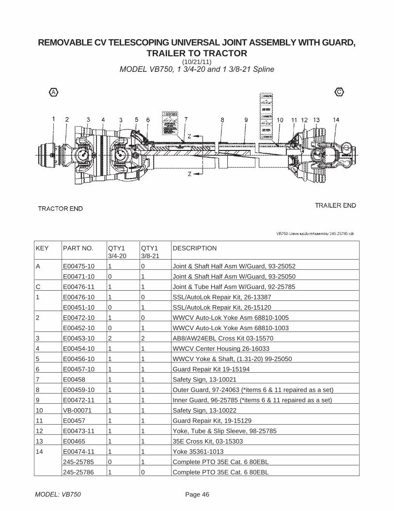
REMOVABLE CV TELESCOPING UNIVERSAL JOINT ASSEMBLY WITH GUARD,TRAILER TO TRACTOR
(10/21/11)MODEL VB750, 1 3/4-20 and 1 3/8-21 Spline
KEY PART NO. QTY13/4-20
QTY13/8-21
DESCRIPTION
A E00475-10 1 0 Joint & Shaft Half Asm W/Guard, 93-25052
E00471-10 0 1 Joint & Shaft Half Asm W/Guard, 93-25050
C E00476-11 1 1 Joint & Tube Half Asm W/Guard, 92-25785
1 E00476-10 1 0 SSL/AutoLok Repair Kit, 26-13387
E00451-10 0 1 SSL/AutoLok Repair Kit, 26-15120
2 E00472-10 1 0 WWCV Auto-Lok Yoke Asm 68810-1005
E00452-10 0 1 WWCV Auto-Lok Yoke Asm 68810-1003
3 E00453-10 2 2 AB8/AW24EBL Cross Kit 03-15570
4 E00454-10 1 1 WWCV Center Housing 26-16033
5 E00456-10 1 1 WWCV Yoke & Shaft, (1.31-20) 99-25050
6 E00457-10 1 1 Guard Repair Kit 19-15194
7 E00458 1 1 Safety Sign, 13-10021
8 E00459-10 1 1 Outer Guard, 97-24063 (*items 6 & 11 repaired as a set)
9 E00472-11 1 1 Inner Guard, 96-25785 (*items 6 & 11 repaired as a set)
10 VB-00071 1 1 Safety Sign, 13-10022
11 E00457 1 1 Guard Repair Kit, 19-15129
12 E00473-11 1 1 Yoke, Tube & Slip Sleeve, 98-25785
13 E00465 1 1 35E Cross Kit, 03-15303
14 E00474-11 1 1 Yoke 35361-1013
245-25785 0 1 Complete PTO 35E Cat. 6 80EBL
245-25786 1 0 Complete PTO 35E Cat. 6 80EBL
Page 47 MODEL: VB750
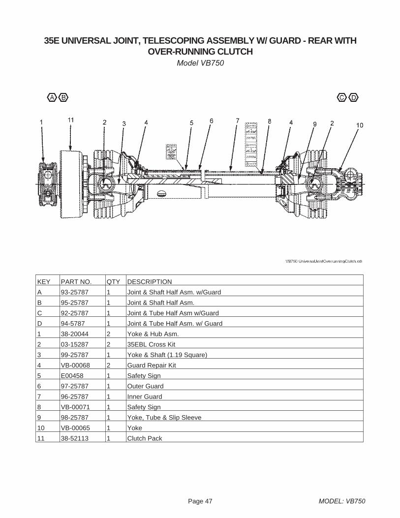
35E UNIVERSAL JOINT, TELESCOPING ASSEMBLY W/ GUARD - REAR WITHOVER-RUNNING CLUTCH
Model VB750
KEY PART NO. QTY DESCRIPTION
A 93-25787 1 Joint & Shaft Half Asm. w/Guard
B 95-25787 1 Joint & Shaft Half Asm.
C 92-25787 1 Joint & Tube Half Asm w/Guard
D 94-5787 1 Joint & Tube Half Asm. w/ Guard
1 38-20044 2 Yoke & Hub Asm.
2 03-15287 2 35EBL Cross Kit
3 99-25787 1 Yoke & Shaft (1.19 Square)
4 VB-00068 2 Guard Repair Kit
5 E00458 1 Safety Sign
6 97-25787 1 Outer Guard
7 96-25787 1 Inner Guard
8 VB-00071 1 Safety Sign
9 98-25787 1 Yoke, Tube & Slip Sleeve
10 VB-00065 1 Yoke
11 38-52113 1 Clutch Pack
MODEL: VB750 Page 48
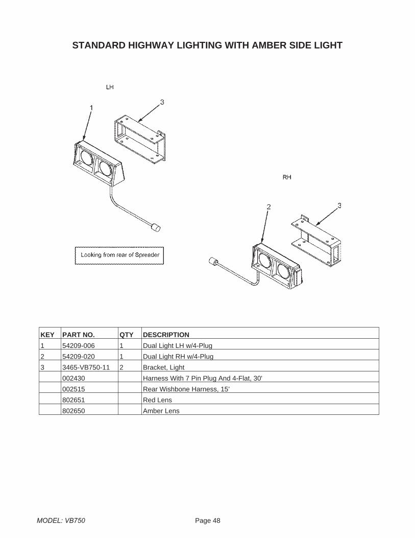
STANDARD HIGHWAY LIGHTING WITH AMBER SIDE LIGHT
KEY PART NO. QTY DESCRIPTION
1 54209-006 1 Dual Light LH w/4-Plug
2 54209-020 1 Dual Light RH w/4-Plug
3 3465-VB750-11 2 Bracket, Light
002430 Harness With 7 Pin Plug And 4-Flat, 30'
002515 Rear Wishbone Harness, 15'
802651 Red Lens
802650 Amber Lens

Page 49 MODEL: VB750
This page intentionally blank.
MODEL: VB750 Page 50
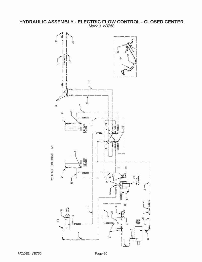
HYDRAULIC ASSEMBLY - ELECTRIC FLOW CONTROL - CLOSED CENTERModels VB750

Page 51 MODEL: VB750
KEY PART NO. QTY DESCRIPTION
1 VB-00182 1 Hose, 8M3K-8FJX-8FJX-90S-56”
2 VB-00183 1 Hose, 8M3K-8FJX-8FJX-90S-59”
3 VB--00184 1 Hose, 8M3K-8FJX-8FJX-42”
4 VB-00185 1 Hose, 8M3K-8FJX-8FJX-90S-17”
5 VB-00186 1 Hose, 8M3K-8FJX-8FJX-90S-11”
6 VB-00187 1 Hose, 8M3K-8FJX-8FJX-28”
7 VB-00188 1 Hose, 6M3K-8FJX-8FJX-90S-37”
8 VB-00189 1 Hose, 6M3K-8FJX-8FJX-90S-43”
9 VB-00190 1 Hose, 8M3K-8FJX-8FJX-90S-210”
10 VB-00191 1 Hose, 8M3K-8FJX-8FJX-90S-206”
11 VB-00192 1 Hose, 8M3K-8FJX-8MP - 132”
12 VB-00193 1 Hose, 8M3K-8FJX-8MP - 132”
13 E21442 1 O-Ring Adapter to JIC 90� 6801-8-10
14 VB-00194 1 Hose, 6M3K-8FJX-8FJX-128”
15 VB-00195 1 Hose, 6M3K-8FJX-8FJX-117”
16 E00484-00 3 Adapter JIC to O-Ring 6400-8-10
17 E21450 4 Adapter 6400-8-12 O-Ring
18 E00485-09 4 ADAPTER TEE 6602-8
19 E00483-09 4 CAP 304-C-8
20 E00496-09 1 LINE CHECK LT-8-O
21 VB-00196 2 Male JIC To Male ORB, 90° Adapter - 6801-8
22 E20328 2 Tee 2703-LN-8
23 E20329 2 Male JIC To FM JIC - 6500-8
24 E00486-09 2 BULKHEAD 2701-LN-8
25 E21447 1 Ftg, Hydraulic, 8MJx8MORB 6400-8-8
26 VB-00197 1 Male JIC to Male ORB, 45° 6802-8-8
27 E23579 1 O-Ring to JIC 90� Adapter 6801-8-12
28 E21456-VB 1 Valve Controlled Flow BG511.5-12SAE
29 E00500 1 Motorized Flow Control
30 E01591 2 Quick Coupler
31 VB-00209 1 Selector Valve HC-VBN22
32 E00067-04 2 Male JIC To Male ORB, 90° Adapter - 6801-8-8
36 E00503-04 1 Flat Plug Connector
37 E00504 3 Cord Clamp
38 E00502 1 Electric Flow Controller
39 VB-00201 1 Str. Bushing, 6410-12-8
Hydraulic Assembly - Electric Flow Control - Closed CenterModels VB750
MODEL: VB750 Page 52
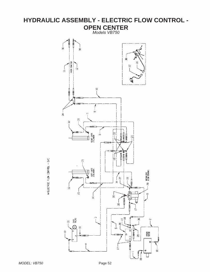
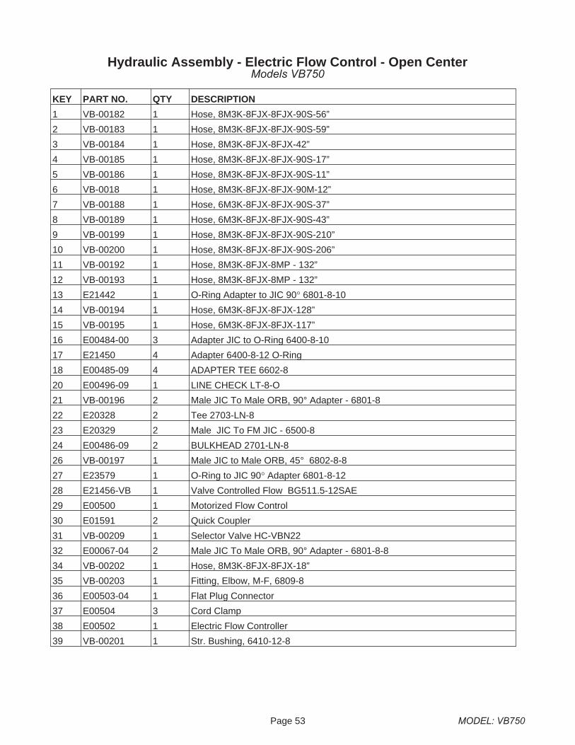
HYDRAULIC ASSEMBLY - ELECTRIC FLOW CONTROL -OPEN CENTER
Models VB750
Page 53 MODEL: VB750
KEY PART NO. QTY DESCRIPTION
1 VB-00182 1 Hose, 8M3K-8FJX-8FJX-90S-56”
2 VB-00183 1 Hose, 8M3K-8FJX-8FJX-90S-59”
3 VB-00184 1 Hose, 8M3K-8FJX-8FJX-42”
4 VB-00185 1 Hose, 8M3K-8FJX-8FJX-90S-17”
5 VB-00186 1 Hose, 8M3K-8FJX-8FJX-90S-11”
6 VB-0018 1 Hose, 8M3K-8FJX-8FJX-90M-12”
7 VB-00188 1 Hose, 6M3K-8FJX-8FJX-90S-37”
8 VB-00189 1 Hose, 6M3K-8FJX-8FJX-90S-43”
9 VB-00199 1 Hose, 8M3K-8FJX-8FJX-90S-210”
10 VB-00200 1 Hose, 8M3K-8FJX-8FJX-90S-206”
11 VB-00192 1 Hose, 8M3K-8FJX-8MP - 132”
12 VB-00193 1 Hose, 8M3K-8FJX-8MP - 132”
13 E21442 1 O-Ring Adapter to JIC 90� 6801-8-10
14 VB-00194 1 Hose, 6M3K-8FJX-8FJX-128”
15 VB-00195 1 Hose, 6M3K-8FJX-8FJX-117”
16 E00484-00 3 Adapter JIC to O-Ring 6400-8-10
17 E21450 4 Adapter 6400-8-12 O-Ring
18 E00485-09 4 ADAPTER TEE 6602-8
20 E00496-09 1 LINE CHECK LT-8-O
21 VB-00196 2 Male JIC To Male ORB, 90° Adapter - 6801-8
22 E20328 2 Tee 2703-LN-8
23 E20329 2 Male JIC To FM JIC - 6500-8
24 E00486-09 2 BULKHEAD 2701-LN-8
26 VB-00197 1 Male JIC to Male ORB, 45° 6802-8-8
27 E23579 1 O-Ring to JIC 90� Adapter 6801-8-12
28 E21456-VB 1 Valve Controlled Flow BG511.5-12SAE
29 E00500 1 Motorized Flow Control
30 E01591 2 Quick Coupler
31 VB-00209 1 Selector Valve HC-VBN22
32 E00067-04 2 Male JIC To Male ORB, 90° Adapter - 6801-8-8
34 VB-00202 1 Hose, 8M3K-8FJX-8FJX-18”
35 VB-00203 1 Fitting, Elbow, M-F, 6809-8
36 E00503-04 1 Flat Plug Connector
37 E00504 3 Cord Clamp
38 E00502 1 Electric Flow Controller
39 VB-00201 1 Str. Bushing, 6410-12-8
Hydraulic Assembly - Electric Flow Control - Open CenterModels VB750
MODEL: VB750 Page 54
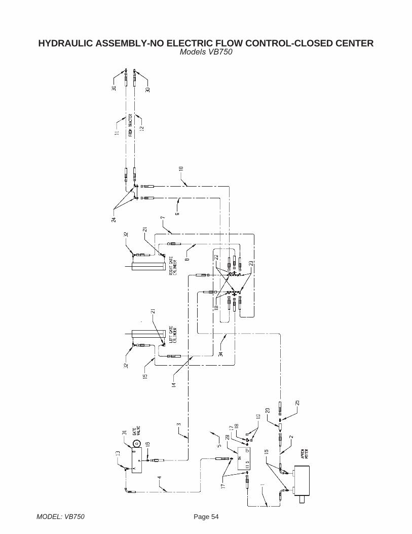
HYDRAULIC ASSEMBLY-NO ELECTRIC FLOW CONTROL-CLOSED CENTERModels VB750

Page 55 MODEL: VB750
KEY PART NO. QTY DESCRIPTION
1 VB-00182 1 Hose, 8M3K-8FJX-8FJX-90S-56”
2 VB-00183 1 Hose, 8M3K-8FJX-8FJX-90S-59”
3 VB-00184 1 Hose, 8M3K-8FJX-8FJX-42”
4 VB-00185 1 Hose, 8M3K-8FJX-8FJX-90S-17”
6 VB-00187 1 Hose, 8M3K-8FJX-8FJX-28”
7 VB-00188 1 Hose, 6M3K-8FJX-8FJX-90S-37”
8 VB-00189 1 Hose, 6M3K-8FJX-8FJX-90S-43”
9 VB-00190 1 Hose, 8M3K-8FJX-8FJX-90S-210”
10 VB-00191 1 Hose, 8M3K-8FJX-8FJX-90S-206”
11 VB-00192 1 Hose, 8M3K-83FJX-8MP - 132”
12 VB-00193 1 Hose, 8M3K-8FJX-8MP - 132”
13 E21442 1 O-Ring Adapter to JIC 90� 6801-8-10
14 VB-00194 1 Hose, 6M3K-8FJX-8FJX-128”
15 VB-00195 1 Hose, 6M3K-8FJX-8FJX-117”
16 E00484-00 3 Adapter JIC to O-Ring 6400-8-10
17 E21450 3 Adapter 6400-8-12 O-Ring
18 E00485-09 3 ADAPTER TEE 6602-8
19 E00483-09 2 CAP 304-C-8
20 E00496-09 1 LINE CHECK LT-8-O
21 VB-00196 2 Male JIC To Male ORB, 90° Adapter - 6801-8
22 E20328 2 Tee 2703-LN-8
23 E20329 2 Male JIC To FM JIC - 6500-8
24 E00486-09 2 BULKHEAD 2701-LN-8
25 E21447 2 Ftg, Hydraulic, 8MJx8MORB 6400-8-8
28 E21456-VB 1 Valve Controlled Flow BG511.5-12SAE
30 E01591 2 Quick Coupler
31 VB-00209 1 Selector Valve HC-VBN22
32 E00067-04 2 Male JIC To Male ORB, 90° Adapter - 6801-8-8
34 VB-00204 1 Hose, 8M3K-8FJX-8FJX-28”
Hydraulic Assembly - No Electric Flow Control - Closed CenterModels VB750
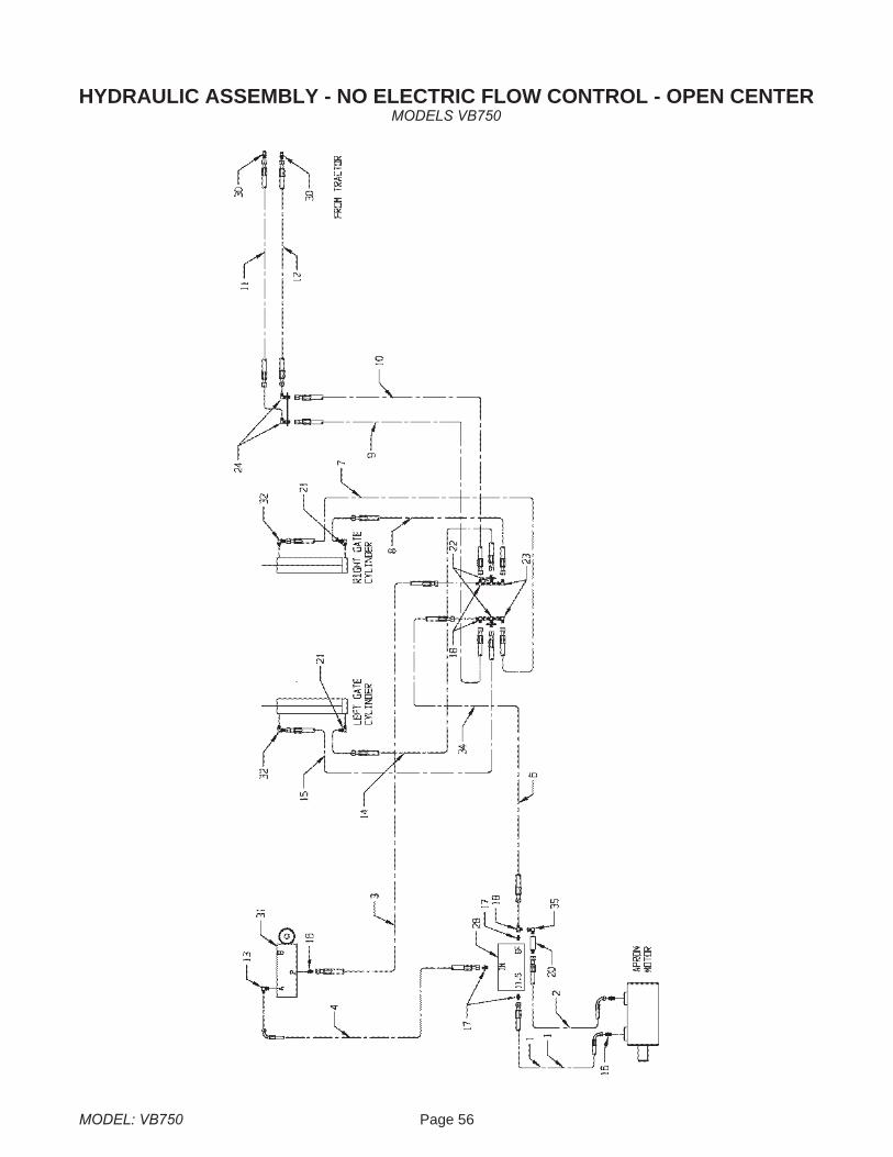
MODEL: VB750 Page 56
HYDRAULIC ASSEMBLY - NO ELECTRIC FLOW CONTROL - OPEN CENTERMODELS VB750

Page 57 MODEL: VB750
KEY PART NO. QTY DESCRIPTION
1 VB-00182 1 Hose, 8M3K-8FJX-8FJX-90S-56”
2 VB-00183 1 Hose, 8M3K-8FJX-8FJX-90S-59”
3 VB-00184 1 Hose, 8M3K-8FJX-8FJX-42”
4 VB-00185 1 Hose, 8M3K-8FJX-8FJX-90S-17”
6 VB-00187 1 Hose, 8M3K-8FJX-8FJX-28”
7 VB-00188 1 Hose, 6M3K-8FJX-8FJX-90S-37”
8 VB-00189 1 Hose, 6M3K-8FJX-8FJX-90S-43”
9 VB-00190 1 Hose, 8M3K-8FJX-8FJX-90S-210”
10 VB-00191 1 Hose, 8M3K-8FJX-8FJX-90S-206”
11 VB-00192 1 Hose, 8M3K-8FJX-8MP - 132”
12 VB-00193 1 Hose, 8M3K-8FJX-8MP - 132”
13 E21442 1 O-Ring Adapter to JIC 90� 6801-8-10
14 VB-00194 1 Hose, 6M3K-8FJX-8FJX-128”
15 VB-00195 1 Hose, 6M3K-8FJX-8FJX-117”
16 E00484-00 3 Adapter JIC to O-Ring 6400-8-10
17 E21450 3 Adapter 6400-8-12 O-Ring
18 E00485-09 3 ADAPTER TEE 6602-8
20 E00496-09 1 LINE CHECK LT-8-O
21 VB-00196 2 Male JIC To Male ORB, 90° Adapter - 6801-8
22 E20328 2 Tee 2703-LN-8
23 E20329 2 Male JIC To FM JIC - 6500-8
24 E00486-09 2 BULKHEAD 2701-LN-8
28 E21456-VB 1 Valve Controlled Flow BG511.5-12SAE
30 E01591 2 Quick Coupler
31 VB-00209 1 Selector Valve HC-VBN22
32 E00067-04 2 Male JIC To Male ORB, 90° Adapter - 6801-8-8
35 VB-00203 1 Fitting, Elbow, M-F, 6809-8
Hydraulic Assembly - No Electric Flow Control - Open CenterModels VB750
MODEL: VB750 Page 58
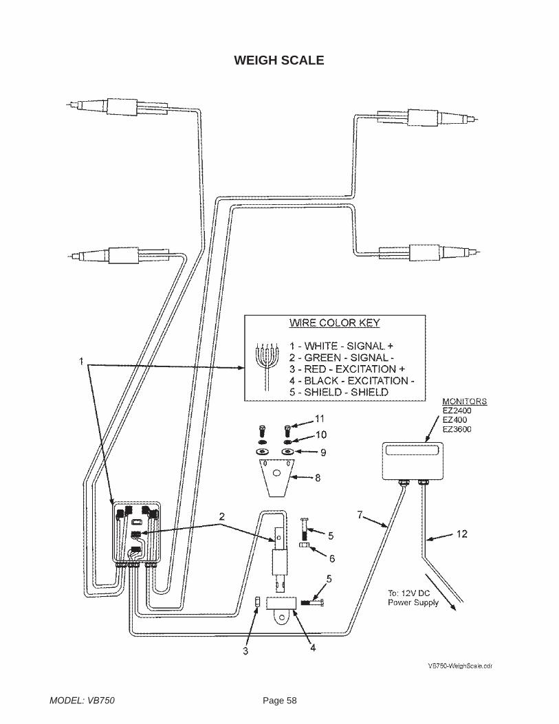
WEIGH SCALE
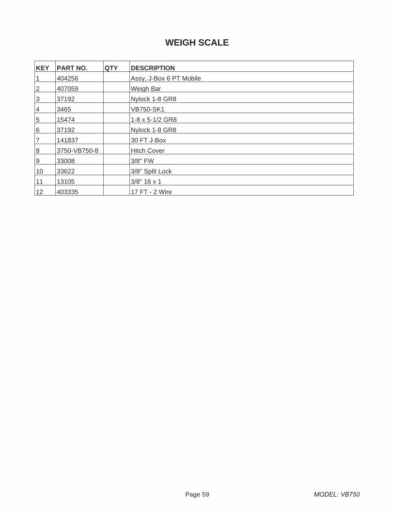
Page 59 MODEL: VB750
KEY PART NO. QTY DESCRIPTION
1 404256 Assy, J-Box 6 PT Mobile
2 407059 Weigh Bar
3 37192 Nylock 1-8 GR8
4 3465 VB750-SK1
5 15474 1-8 x 5-1/2 GR8
6 37192 Nylock 1-8 GR8
7 141837 30 FT J-Box
8 3750-VB750-8 Hitch Cover
9 33008 3/8" FW
10 33622 3/8" Split Lock
11 13105 3/8" 16 x 1
12 403335 17 FT - 2 Wire
WEIGH SCALE

LIMITED WARRANTY STATEMENT
Meyer’s Equipment Mfg. Corp. warrants each new Meyer’s E.M.C. product to be free from:defects in material and workmanship. This warranty is applicable only for the normal servicelife expectancy of the product or components, not to exceed 12 consecutive months fromthe date of delivery of the new Meyer’s E.M.C. product to the original purchaser.
Genuine Meyer’s E.M.C. replacement parts and components will be warranted for 365 daysfrom date of purchase, or the remainder of the original equipment warranty period, which-ever is longer.
Under no circumstances will it cover any merchandise or components thereof, which, in theopinion of the company, has been subjected to misuse, unauthorized modifications, alter-ation, and accident or if repairs have been made with parts other than those obtainablethrough Meyer’s E.M.C.
Our obligation under this warranty shall be limited to repairing or replacing, free of charge tothe original purchaser, any part that, in our judgement, shall show evidence of such defect,provided further that such part shall be returned within thirty (30) days from date of failure toMeyer’s E.M.C., routed through the dealer and distributor from whom the purchase wasmade, transportation charges prepaid. Labor charges will be paid at a specified rate. Mile-age will not be paid.
This warranty shall not be interpreted to render Meyer’s E.M.C. liable for injury or damagesof any kind or nature to person or property. This warranty does not extend to the loss ofcrops, loss because of delay in harvesting, or any expense or loss incurred for labor, substi-tute machinery, rental or for any other reason.
In addition to the above limited warranty statement the following applies:Meyer’s E.M.C. will replace (F.O.B. Dorchester) as Meyer’s E.M.C. elects, for 10 years frompurchase date - any polyethylene plastic boards which compromises the floor, sides, rear orfront of the box portion of the manure spreader box (not labor) from rotting under normal us-age to the original owner.
Except as set forth above, Meyer’s E.M.C. shall have no obligation or liability of anykind on account of any of its equipment and shall not be liable for special or conse-quential damages. Meyer’s E.M.C. disclaims any implied warranty or merchantabilityor fitness for a particular purpose. Some states or provinces do no permit limitationsor exclusions of implied warranties or incidental or consequential damages, so thelimitations or exclusion in this warranty may not apply.
P