metrotm - billard · installation manual service department p.o. box 68 bristol, wi 53104 tm...
TRANSCRIPT

Metro
POCKET BILLIARD TABLE
INSTALLATION MANUAL
www.brunswickbilliards.comSERVICE DEPARTMENT P.O. BOX 68 BRISTOL, WI 53104
TM
51-905486-001 SEPTEMBER 2005

PAGE 2 BRUNSWICK INSTALLATION MANUAL
METRO
NOTE: Please use the instructions in this manual to assemble the tablesshown below. Illustrations may be different depending on the tablebeing assembled. Also note that careful handling of all components
will assure damage-free assembly.

BRUNSWICK INSTALLATION MANUAL PAGE 3
METRO
BASEFRAME AND LEG ASSEMBLY
FIGURE ONE
Step #1: Loosely assemble the two side sills to the fourcross support sills as shown in Figure One with 5/16-18x 4” hex head bolts, 5/16 flat washers and 5/16-18 weldnuts.
Step #2: Attach two slate attach cleats to each end of thebaseframe as shown in Figure One with 5/16-18 x 5-1/2”hex head bolts, 5/16 flat washers and 5/16-18 hex nuts.Position flush with the top of the sill and securely tighten
FIGURE ONE
FIGURE TWO
Step #3: Set the legs out with the levelers up. Run outabout 1/4” to assure that they are free to rotate.
Step #4: Set the legs out, upright at the four corners andset the assembled baseframe on top.
FIGURE TWO
FIGURE THREE
Step #5: Set a leg attach bracket in each corner of thebaseframe on top of the leg.
Step #6: Loosely attach the brackets to the leg using 5/16-18 x 1-1/4” hex head bolts and 5/16 flat washers.
Step #7: Loosely attach the baseframe to the bracketsusing 3/8-16 x 2-3/4” hex head bolts, 3/8 flat washers and3/8-16 hex nuts.
FIGURE THREE

PAGE 4 BRUNSWICK INSTALLATION MANUAL
METRO
BASEFRAME AND LEG ASSEMBLY(CONTINUED)
FIGURE FOUR
Step #8: Measure the baseframe assembly diagonallyand adjust as required to obtain the same measurementto assure the baseframe is square. With all joints flushand legs aligned properly, tighten all hardware securely.
FIGURE FOUR
FIGURE FIVE
Step #9: Screw #10 x 1” pan head tapping screwsthrough the top of each leg bracket into the leg.
FIGURE FIVE
FIGURE SIX
Step #10: Position the baseframe and leg assembly in itsfinal location. Level the baseframe with your preferredlevel by rotating the leg levelers. The levelers should berotated out atleast 1/4” to allow for further leveling whenthe slate is attached.
NOTE: Try to leave atleast 5’ between the outer edgeof the baseframe to any wall.
FIGURE SIX
BRUNSWICK INSTALLATION MANUAL PAGE 5
METRO
SLATE ASSEMBLY AND LEVELING
FIGURE ONE
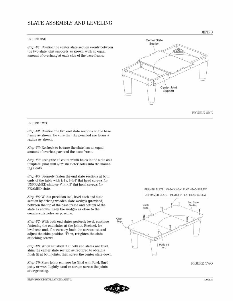
Step #1: Position the center slate section evenly betweenthe two slate joint supports as shown, with an equalamount of overhang at each side of the base frame.
FIGURE ONE
FIGURE TWO
Step #2: Position the two end slate sections on the baseframe as shown. Be sure that the penciled arc forms aradius as shown.
Step #3: Recheck to be sure the slate has an equalamount of overhang around the base frame.
Step #4: Using the 12 countersink holes in the slate as atemplate, pilot drill 5/32" diameter holes into the mount-ing cleats.
Step #5: Securely fasten the end slate sections at bothends of the table with 1/4 x 1-3/4" flat head screws forUNFRAMED slate or #14 x 3" flat head screws forFRAMED slate.
Step #6: With a precision tool, level each end slatesection by driving wooden slate wedges (provided)between the top of the base frame and bottom of theslate as shown. Keep the wedges as close to thecountersink holes as possible.
Step #7: With both end slates perfectly level, continuefastening the end slates at the joints. Recheck forlevelness and, if necessary, back the screws out andadjust the shim position. Then, retighten the slateattaching screws.
Step #8: When satisfied that both end slates are level,shim the center slate section as required to obtain aflush fit at both joints, then screw the center slate down.
Step #9: Slate joints can now be filled with Rock Hardputty or wax. Lightly sand or scrape across the jointsafter grouting.
FIGURE TWO
PAGE 6 BRUNSWICK INSTALLATION MANUAL
METRO
SLATE ASSEMBLY AND LEVELING(CONTINUED)
FIGURE THREE
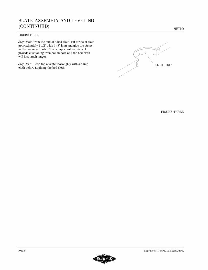
Step #10: From the end of a bed cloth, cut strips of clothapproximately 1-1/2" wide by 8" long and glue the stripsto the pocket cutouts. This is important as this willprovide cushioning from ball impact and the bed clothwill last much longer.
Step #11: Clean top of slate thoroughly with a dampcloth before applying the bed cloth.
FIGURE THREE

BRUNSWICK INSTALLATION MANUAL PAGE 7
METRO
ATTACHING BILLIARD CLOTH TOUNFRAMED SLATE
Before attaching the billiard cloth, clean slate thoroughly.
FIGURE ONE
Step #1: Lay the bed cloth over the top of the slate, napside up. Leave an equal amount of cloth overhang at theends and sides of the slate.
FIGURE ONE
FIGURE TWO
Step #2: At the head end of the table, fold the cloth backaway from the edge of the slate and spray a coat ofcontact adhesive (not included) as indicated by theshaded area of the edge of the slate. Hold the canapproximately 4-8" from the area to be coated. Coat theunderside of the slate also. Place a piece of protectivepaper or card board on the top surface of the cloth.
CAUTION: Do not allow any adhesive to get on thetop surface of the cloth.
FIGURE TWO
FIGURE THREE
Step #3: Attach the cloth at #1.
Step #4: Stretch the cloth across the table at #2. Foldthe cloth overhang underneath the edge of the slate atthe end.
Step #5: Fold the cloth back at the foot end of the tableand repeat Step 1.
Step #6: Stretch the cloth from #1 to #3 and press intoposition.
Step #7: Stretch the cloth #3 to #4, pulling from #1 and#2. Press into place.
FIGURE THREE

PAGE 8 BRUNSWICK INSTALLATION MANUAL
METRO
ATTACHING BED CLOTH TOFRAMED SLATE
Before attaching the billiard cloth, clean slate thoroughly.
FIGURE ONE
Step #1: Lay the bed cloth over the top of the slate, napside up, with the nap running from the head end to thefoot end of the table.
NOTE: In determining the direction of the nap, runyour hand lightly over the surface of the cloth. If itmeets resistance, it is going against the nap.
Step #2: Leave only enough cloth overhang at the headend and left side to permit tacking into the wood slateframe. Leave the balance of cloth overhang at the footend and right side.
NOTE: Do not spread tacks on the bed cloth. Keep themin a container that slides over the cloth.
Step #3: Tack or staple the cloth securely to the woodframe at #1 with two tacks or staples approximately 2"apart.
Step #4: Stretch the cloth across the table and tack orstaple securely at #2 with two tacks or staples 2" apart.
FIGURE ONE
FIGURE TWO
Step #5: Stretch the cloth from #1 to #3 and tack orstaple securely into the wood frame at the left side of thetable. See Figure B.
Step #6: Stretching the cloth across the table from #3and pulling from #2, tack or staple the cloth at #4.
FIGURE TWO
FIGURE THREE
Step #7: On the left side, stretch the cloth tightly from#1 toward the side pocket opening and tack or staplesecurely at #5.
Step #8: Repeat Step 5, stretching the cloth from #3 andtacking or stapling at #6.
Step #9: On the right side of the table, grasp the clothfirmly and stretch across the table from #5 and towardthe side pocket from #2 and tack or staple at #7.
Step #10: Repeat Step 7, stretching from #6 and towardthe side pocket from #4 and tack or staple at #8. FIGURE THREE

BRUNSWICK INSTALLATION MANUAL PAGE 9
METRO
ATTACHING BED CLOTH TOFRAMED SLATE (CONTINUED)FIGURE FOUR
Step #11: At location #9, cut a short slit in the cloth atthe edge centered on the side pocket opening. Grasp thecloth firmly above this slit, pull the cloth into the sidepocket opening and tack or staple to the wood frame.Complete fastening of the cloth to the side pocketopening, making sure the cloth is tacked or stapled to thewood frame.
Step #12: Stretching the cloth tightly across the tablefrom location #9, repeat Step 11 at location #10.
FIGURE FIVE
Step #13: At the head end of the table, tack or staple thecloth at location #11, maintaining uniform overhang.
Step #14: Pull the cloth from location #11 towardlocation #12 and tack or staple securely along the woodframe, keeping the cloth even along the head end.
Step #15: Stretch the cloth firmly from location #11 tothe foot end of the table and tack or staple at location#13.
Step #16: Stretch the cloth tightly from locations #12and #13 toward location #14 and tack or staple securelyalong the wood slate frame.
FIGURE SIX
Step #17: Tack or staple all of the left side on 2" centerskeeping the cloth even along the wood frame.
Step #18: Tack or staple the balance of the head end on2" centers also keeping the cloth even along the woodframe.
Step #19: Stretch the cloth tightly toward the foot end ofthe table, tacking or stapling on 2" centers along thewood frame at the foot end.
Step #20: Stretch the cloth tightly across the table to theright side, tacking or stapling on 2" centers all the wayalong the wood frame at the right side.
FIGURE SEVEN
Step #21: Stretch the cloth into the corner pocketopenings and tack or staple to the wood slate frame.
Step #22: Trim off excess cloth around the perimeter ofthe slate. Locate the eighteen (18) rail attach holes andcut clearance holes in the cloth with a sharp knife.
NOTE: Occasionally cloth will stretch, leaving wrinklesat the pockets. To retighten, remove apron, one end railand one side rail. Pull cloth taut, and retack or restaplealong the open end and side to restore original tightness.
FIGURE FOUR
FIGURE FIVE
FIGURE SIX
FIGURE SEVEN

PAGE 10 BRUNSWICK INSTALLATION MANUAL
METRO
ATTACHING RAIL CLOTH
CORNER POCKETFIGURE ONE
Step #1: Place cloth on rail with the back side down.The cloth should have equal amount of overhang at bothends of rail and extend 1/2" over the featherstrip grooveon the cushion side as shown.
Step #2: Except for approximately 3" at end of rail, tapfeatherstrip down with a tapping block and hammer,starting at center of rail. Stretch cloth tightly towardeach end of rail and tap featherstrip down.
FIGURE ONE
FIGURE TWO
Step#3: At each end of rail, pull the cloth toward therubber cushion an additional 3/4". Then tap remainder offeatherstrip down.
FIGURE TWO
FIGURE THREE
Step #4: Trim the cloth on cushion side of featherstripalong the total length of featherstrip as illustrated.
FIGURE THREE
FIGURE FOUR
Step #5: Fold the cloth down over front of rail, thenusing thumb and forefinger as a guide along front edgeof the cushion to keep the tapping block at rear edge offeatherstrip, tap the featherstrip down flush with railsurface as shown.
NOTE: Never try to tap a featherstrip flush with just ahammer as you will surely dent the rail surface behind thefeatherstrip.
FIGURE FOUR
FIGURE FIVE
Step #6: Turn rail over and at corner pockets fold thecloth over the mitred edge as shown, stretching tightlyand working out any wrinkles as you staple three placesin area shown.
FIGURE FIVE

BRUNSWICK INSTALLATION MANUAL PAGE 11
METRO
ATTACHING RAIL CLOTH(CONTINUED)
FIGURE SIX
Step #7: Staple three places along the rear edge of thepocket facing X, then trim off excess cloth at pocket area.
Step #8: If rail is an end rail, repeat Step 7 at othercorner pocket. Then, starting at center of rails, stretchcloth tightly over cushion and staple at bottom of railworking toward each end.
FIGURE SIX
FIGURE SEVEN
Step #9: Trim excess cloth from bottom of rail flushwith edge of cloth relief groove.
FIGURE SEVEN
SIDE POCKETFIGURE EIGHT
Step #10: At side pocket, stretch the cloth tightly overnose of cushion and staple three places as shown.
FIGURE EIGHT
FIGURE NINE
Step #11: Slit the cloth up to the edge of cushion noseas shown. Then firmly pull the small strip to the rear ofthe cushion and staple at rear of facing.
FIGURE NINE
FIGURE TEN
Step #12: Hold the small fold in place with thumb andforefinger and firmly hold it down over facing. Thenstaple at rear of facing and at bottom of rail as shown.
Step #13: Trim excess cloth as required.
FIGURE TEN

PAGE 12 BRUNSWICK INSTALLATION MANUAL
METRO
RAIL AND APRON ASSEMBLY
FIGURE ONE
Step #1: Position the six rails upside down in theirrespective locations on a protected surface as shown.
FIGURE ONE
FIGURE TWO
Step #2: With the rails laid out, drive roll pins into theend of each rail. Leave 1/8” of roll pin exposed. Positionthe sides and corner castings on rails using so pins alignwith clearance holes.
FIGURE TWO
FIGURES THREE AND FOUR
Step #2: Attach the corner and side castings to the railsusing 5/16-18 x 1-3/4” hex head bolts, 5/16 flatwashersand 5/16-18 weld nuts. Tighten finger tight, square therail assembly and tighten all casings securely.
NOTE: the castings will not be flush with the top andback of the rails you will have about a 1/8” overhang.
FIGURE THREE
FIGURE FOUR
BRUNSWICK INSTALLATION MANUAL PAGE 13
METRO
RAIL AND APRON ASSEMBLY(CONTINUED)
FIGURES FIVE AND SIX
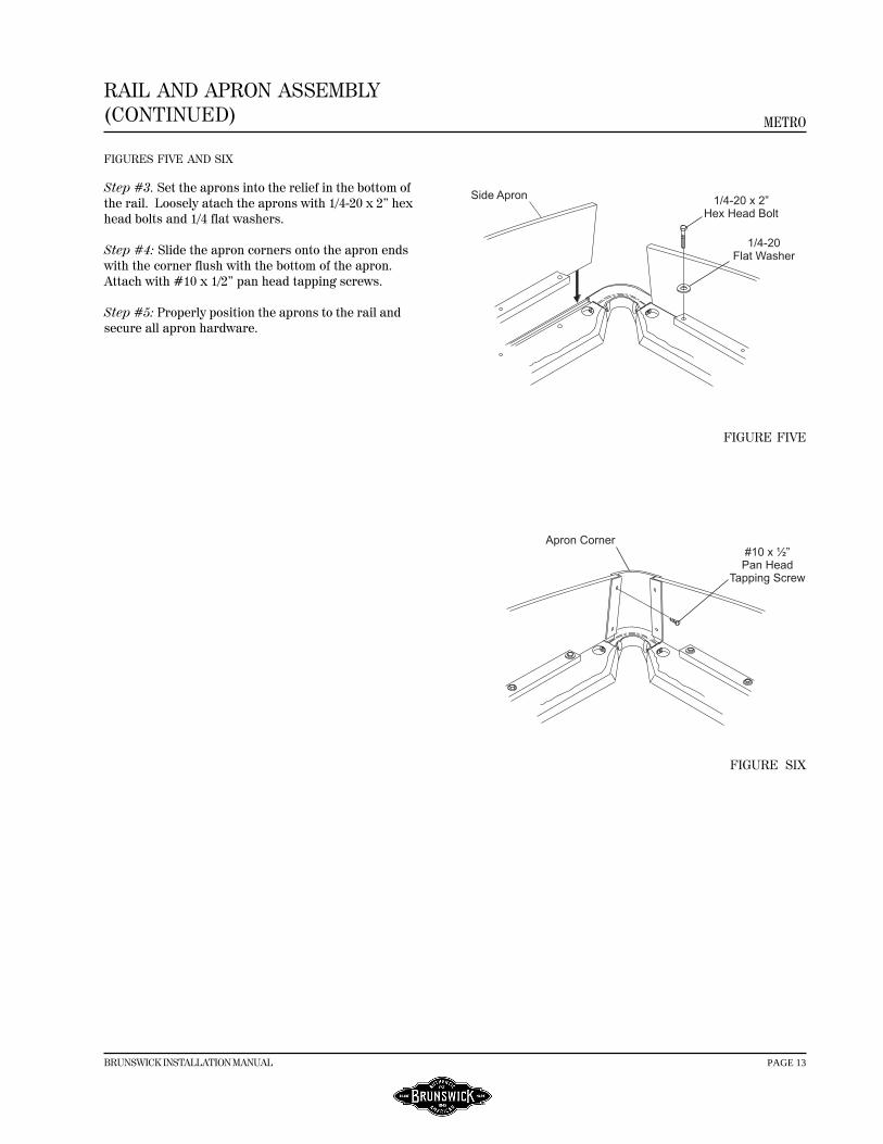
Step #3. Set the aprons into the relief in the bottom ofthe rail. Loosely atach the aprons with 1/4-20 x 2” hexhead bolts and 1/4 flat washers.
Step #4: Slide the apron corners onto the apron endswith the corner flush with the bottom of the apron.Attach with #10 x 1/2” pan head tapping screws.
Step #5: Properly position the aprons to the rail andsecure all apron hardware.
FIGURE FIVE
FIGURE SIX

PAGE 14 BRUNSWICK INSTALLATION MANUAL
METRO
RAIL AND APRON ASSEMBLY(CONTINUED)
FIGURE SIX
Step #6: Carefully tuen the rail and apron over andlower it over the table.
CAUTION: Do not let the rail assembly “twist” or“bow” while turning as the strain may cause the railto crack at the ends.
Step #7: Align the eighteen machine studs with theeighteen clearance holes through the slate, and lowerassembly onto the slate.
FIGURE SIX
FIGURE SEVEN
Step #8: Thread the 3/8-16 hex nut and dome washeronto the machine stud (three places) at the ends of thetable and tighten securely.
Step #9: Making sure that the side rails are in a straightline as sighted down the length of the table (cushionside), fasten the side rails securely with remaining nutsand dome washers.
FIGURE SEVEN
FIGURE EIGHT
Step #10: Install the side and corner pockets by pullingthem up from under the rail and apron assembly. Placethem in the castings and carefully fit and trim end to fitfliush behind the cushion facing. Use a scribe or nail setas a drift pin to locate castings hole. Install with #10-24x 5/8” socket head machine screws and #10 externaltooth washers.
FIGURE EIGHT
FIGURE NINE
Step #11: Thoroughly brush the area on which the bed
Step #12: Locate and install bed spots for each type oftable as shown.
FIGURE NINE

BRUNSWICK INSTALLATION MANUAL PAGE 15
METRO
BALL RETURN SYSTEM
FIGURE ONE
Step #1: Position the ball receiver box at the center ofthe bottom of the foot end sill. Securely attach with eight#10 x 2” drill point screws and #10 fender washers.
NOTE: This procedure should be done prior toinstallation of the slate.
FIGURE ONE
FIGURE TWO
Step #2: Install the side and corner pockets by pullingthem up from under the rail and apron assembly. Placethem in the castings and carefully fit and trim end to fitfliush behind the cushion facing. Use a scribe or nail setas a drift pin to locate castings hole. Install with #10-24x 5/8” socket head machine screws and #10 externaltooth washers.
NOTE: This system requires four head gully boots.Use left-hand and right-hand head pockets at the footof the table.
FIGURE TWO
FIGURE THREE
Step #3: Attach the gulley track to the bottom of the sillsusing #10 x 1-1/4” pan head tapping screws. Use twoscrews per cleat, one into the bottom of the sill and oneinside. Install the foot end tracks first then butt thehead track to the foot track.
NOTE: To obtain a smoother roll the wires can be bentto match.
FIGURE THREE