metrology and sensing - uni-jena.de · 2016-11-05 · spectral filtering straylight suppression...
TRANSCRIPT

www.iap.uni-jena.de
Metrology and Sensing
Lecture 5: Interferometry I
2016-11-09
Herbert Gross
Winter term 2016

2
Preliminary Schedule
No Date Subject Detailed Content
1 18.10. Introduction Introduction, optical measurements, shape measurements, errors,
definition of the meter, sampling theorem
2 19.10. Wave optics (ACP) Basics, polarization, wave aberrations, PSF, OTF
3 01.11. Sensors Introduction, basic properties, CCDs, filtering, noise
4 08.11. Fringe projection Moire principle, illumination coding, fringe projection, deflectometry
5 09.11. Interferometry I (ACP) Introduction, interference, types of interferometers, miscellaneous
6 22.11. Interferometry II Examples, interferogram interpretation, fringe evaluation methods
7 29.11. Wavefront sensors Hartmann-Shack WFS, Hartmann method, miscellaneous methods
8 06.12. Geometrical methods Tactile measurement, photogrammetry, triangulation, time of flight,
Scheimpflug setup
9 13.12. Speckle methods Spatial and temporal coherence, speckle, properties, speckle metrology
10 20.12. Holography Introduction, holographic interferometry, applications, miscellaneous
11 03.01. Measurement of basic
system properties Bssic properties, knife edge, slit scan, MTF measurement
12 10.01. Phase retrieval Introduction, algorithms, practical aspects, accuracy
13 17.01. Metrology of aspheres
and freeforms Aspheres, null lens tests, CGH method, freeforms, metrology of freeforms
14 24.01. OCT Principle of OCT, tissue optics, Fourier domain OCT, miscellaneous
15 31.01. Confocal sensors Principle, resolution and PSF, microscopy, chromatical confocal method

3
Content
Introduction
Interference
Types of interferometers

4
Interferometry
Basic idea:
- separation of a wave into two beams (test and reference arm)
-every beam surpasses different paths
- superposition and interference of both beams
- analysis of the pattern
Different setups for:
- the beam splitting
- the superposition
- the referencing
Different path lengths
Difference equivalent of one fringe
Measurement of plates:
Haidinger fringes of equal inclination
Newton fringes of equal thickness
Ref: W. Osten
1 1 2 2 wn t n t N t
2wt
n
5
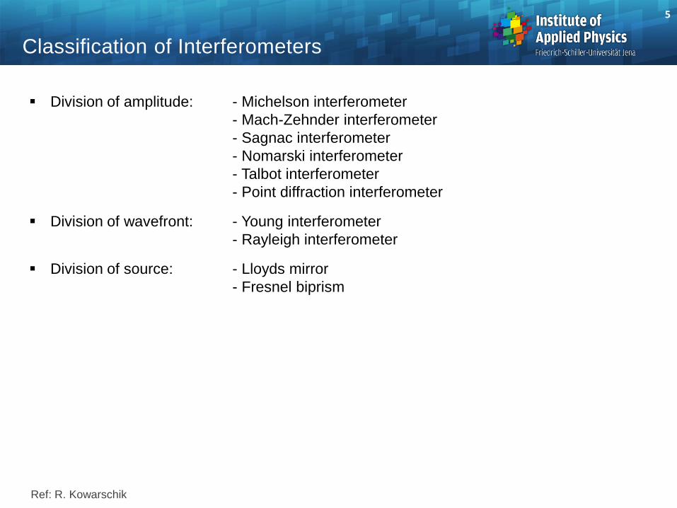
Classification of Interferometers
Division of amplitude: - Michelson interferometer
- Mach-Zehnder interferometer
- Sagnac interferometer
- Nomarski interferometer
- Talbot interferometer
- Point diffraction interferometer
Division of wavefront: - Young interferometer
- Rayleigh interferometer
Division of source: - Lloyds mirror
- Fresnel biprism
Ref: R. Kowarschik

6
Classification of Interferometers
Two-beam interferometers: - Michelson
- Twyman Green
- Sagnac
- Young
- Mach-Zehnder
- Rayleigh
- Fizeau
- Shearing
- Mireau
- Linnik
Multi-beam interferometers: - Fabry-Perot
- Lummer-Gehrke
Ref: R. Kowarschik

7
Localization of Fringes
Interference volume for a plate
Interference volume for a wedge
Ref: R. Kowarschik
volume of
interference
fringes
incident
light back side
reflectedfront side
reflected
volume of
interference
fringes
incident
light
back side
reflected
front side
reflected

8
Interference of Two Waves
Superposition of two plane waves:
1. Intensity
2. Phase difference
Spacing of fringes
Interference of two spherical waves
More complicated geometry
),,(cos2²²),,( 2121 zyxAAAAzyxI
rkkzyxzyxzyx
)(),,(),,(),,( 1212
Ref.: B. Dörband
2sin2
ns
9
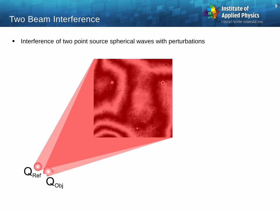
Two Beam Interference
Interference of two point source spherical waves with perturbations

10
Two Beam Interference
Interference of two point source spherical waves

11
Two Beam Interference
Interference of two plane waves under different directions
Fringe distance s 1212
2
eenkks

12
Two Beam Interference
Interference of two plane waves
with finite spectral width w
1
0
))),,,(cos()()(2)²()²((1
),,( 2121
01
dzyxAAAAzyxI

13
Two Beam Interference
Interference of two spherical waves with finite bandwidth in x/z
Delay rotated cone of maximum contrast
bandwidth 20 nm bandwidth 60 nm bandwidth 100 nm
no
delay
delay
5 ms

14
Haidinger Fringes
Fringes of equal inclination:
Haidinger
Every inclination creates an individual delay in the plate

Two beam interference of two waves:
- propagation in the same direction
- same polarization
- phase difference smaller than axial length of coherence
Coherent superposition of waves
Difference of phase / path difference
Number of fringes
location of same phase
Conrast
122121
2
21
cos2
IIII
EEI
122
s
sN
2
12
21
21
minmax
minmax2
II
II
II
IIK
Two Beam Interference

Two beam interference at a plane plate
- Fresnel fringes of equal thickness
- Haidinger fringes of equal inclination
Path difference
:
transparent
plane plate
detector
source
d
1
2
n
2sin2
2cos2 1
22
2
ndnds
Interference Fringes at a Plane Plate

17
Interference at a Plane-Parralle Plate
Multiple reflection superposition
Airy formulas
T: tranmittance
R: Reflectance
Ref: R. Kowarschik
n
n
n’ h’
r, t Reflection,
Transmission Coeff.
n n’
r’, t’ Reflection,
Transmission Coeff.
n’ n
’
Plane monochr.
wave
)(
22
2
)(
2sin4)1(
2sin4
ir I
RR
R
I
)(
22
2)(
2sin4)1(
it I
RR
TI

Multi beam interference
Intensity of pattern
Finesse determines the contrast d
n
1
2I( )
2m (2m+1) (2m+2)
R = 0.2
R = 0.6
R = 0.9
cos21
)1(2
2
RR
RIT
R
RF
1
2
2/1
Interference at a Plane Plate

Spectral filtering
Straylight suppression
Diameter adaptation
lensL1
lensL2
lensL3
lensL4
lensL5
LinseL6
CCD-camera
prism group
test surfaceM1
beam splitter
M1
stopB1
stopB2
stopB3
disrances1
distanceL1
distanceL2
distanceL3
distances2
D :2.5 mm D :
3.81 mm
D :10.0 mm D :
7.72 mm
D :3.81 x 9.49 mm
reference arm
straylight suppression and diameter adaptation
spectral filtering
detection
More complex Setup of an Interferometer

20
Real Interferometers
Ref: R. Kowarschik

21
Interferometers
Accuracy of interferometers
Ref: F. Hoeller

test surface
beamsplitter
reference surface
here: flat
illumination
to detector
path difference
mRrm
Test by Newton Fringes
Reference surface and test surface with nearly the same radii
Interference in the air gap
Reference flat or curved possible
Corresponds to Fizeau setup
with contact
Broad application in simple
optical shop test
Radii of fringes
22
Ref: W. Osten

spherical aberration coma
tilt astigmatism
Example Interferograms

Fizeau surface as part of the system work as reference
Fizeau surface near to test surface:
- large common path, insensitiv setup
- small cavity length
The test surface is imaged onto the detector
Fizeau Interferometer
detector
beam
splitter
collimator
plane test
surface
light
source
Fizeau
surface
stop
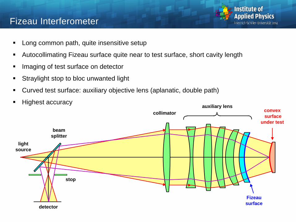
Fizeau Interferometer
Long common path, quite insensitive setup
Autocollimating Fizeau surface quite near to test surface, short cavity length
Imaging of test surface on detector
Straylight stop to bloc unwanted light
Curved test surface: auxiliary objective lens (aplanatic, double path)
Highest accuracy
detector
beam
splitter
collimatorconvex
surface
under test
light
source
Fizeau
surface
auxiliary lens
stop

no common path setup, sensitive
long distances, measurement of samples with small effects
beam
combiner
source
beam splitter
mirror
mirror
test arm
reference arm
detector
sample
Mach-Zehnder Interferometer
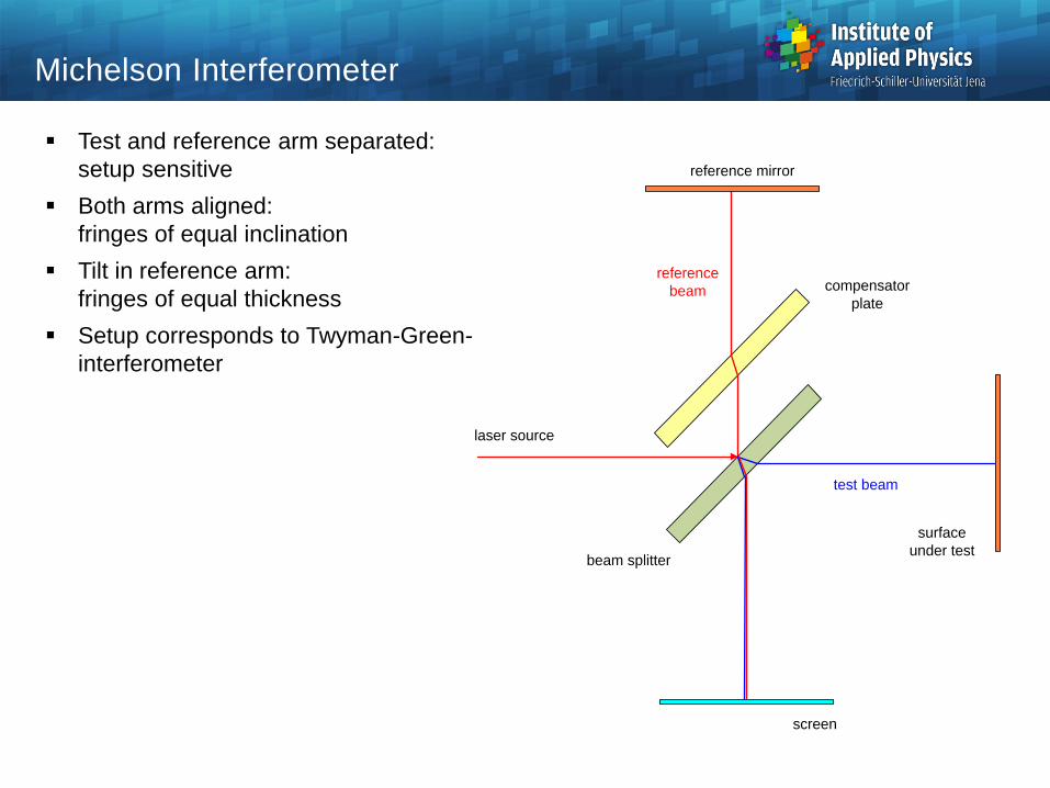
Test and reference arm separated:
setup sensitive
Both arms aligned:
fringes of equal inclination
Tilt in reference arm:
fringes of equal thickness
Setup corresponds to Twyman-Green-
interferometer
screen
reference mirror
laser source
compensator
plate
surface
under test
test beam
reference
beam
beam splitter
Michelson Interferometer

28
Michelson Interferometer
Visibility of fringes
Ref: R. Kowarschik
Haidinger Fringes Fizeau Fringes
B
S
S2’ S1’
M2
M1 M2’
S
B
S2’
S1’
M2
M1
M2’
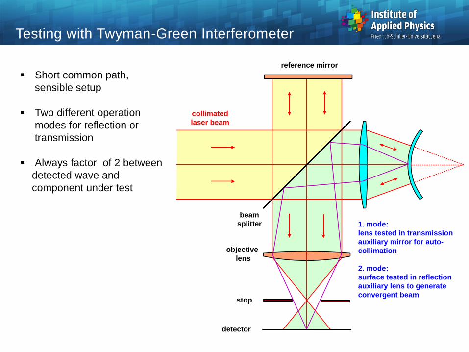
Testing with Twyman-Green Interferometer
Short common path,
sensible setup
Two different operation
modes for reflection or
transmission
Always factor of 2 between
detected wave and
component under test
detector
objective
lens
beam
splitter 1. mode:
lens tested in transmission
auxiliary mirror for auto-
collimation
2. mode:
surface tested in reflection
auxiliary lens to generate
convergent beam
reference mirror
collimated
laser beam
stop

Separation of wavefront:
self reference
Interferograms are looking completly different
Aperture reduced due to shear
Splitting and shift of wavefront:
- by thin plate
- by grating
d
Shearing Interferometer
source
shear
distance

Schematic drawing of sheared wavefronts
Typical interferogram
Shearing Interferometer
shear distance
wavefront W
x

Compact setup
Modified Mach-Zehnder setup with telescope
Radial Shearing Interferometer
beam splitterwavefront under
test
wavefront with
radial shear
lens
beam splitter
source
beamsplitter
mirror
mirror
test arm
reference arm
detector
telescope for
change of diameter
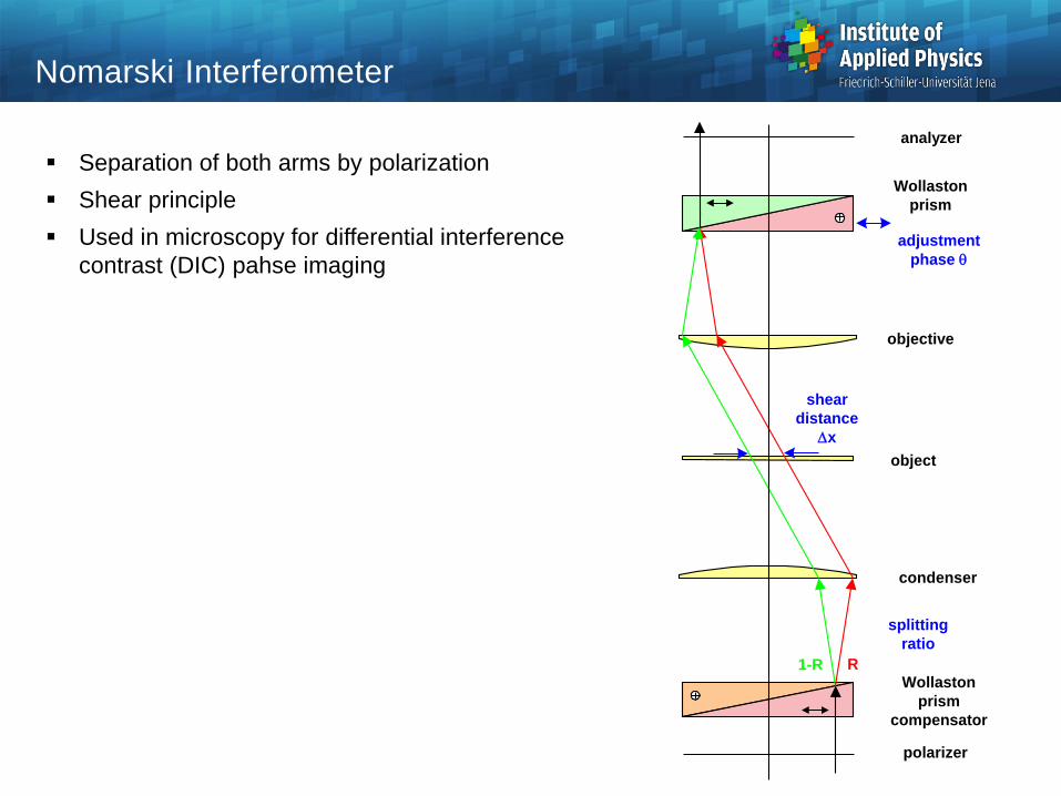
Separation of both arms by polarization
Shear principle
Used in microscopy for differential interference
contrast (DIC) pahse imaging
Nomarski Interferometer
condenser
object
Wollaston
prism
Wollaston
prism
compensator
objective
polarizer
analyzer
shear
distance
x
adjustment
phase
splitting
ratio
R1-R

34
Point Diffraction Interferometer
Full setup according to Smartt

Focussing onto a transparent plagte with pinhole
Pinhole creates a reference spherical wave
Optimization of contrast:
- size of pinhole
- numericalaperture
- transparency of the plate
Very stable setup
transparent plate
with pinhole
wavefront
under test reference
wavefront
Point Diffraction Interferometer

36
Fabry-Perot Interferometer
Setup of an etalon
Applications:
- spectral line resolution
- laser mode selection
Ref: R. Kowarschik
B Fabry-Perot Etalon
Point source
h’
n’

37
Fabry-Perot Interferometer
Intensity
Finesse
Transmission
Contrast
Ref: R. Kowarschik
1
2
22
)(
)(
2sin
1
21
11
R
R
R
A
I
Ii
t
R
RF
1
2
max
)(
)(
11
R
A
I
Ii
t
p
2
22
min
)(
)(
max
)(
)(
41
1
1
F
R
R
I
I
I
I
C
i
t
i
t

38
Fabry-Perot Interferometer
Intrumental functions
Ref: R. Kowarschik
Properties )(W FRP
Absorption
Surface
imperfections
Finite range of
incidence
A
2
HF
FF
F
h 2
1
)(cos
1
0
AA
d
2
H
h
2
F )(cos
1
2
2
2
(sin)1(
41
1
d
R
R
R
T
d
mmm
m
),(0
)()( hfH
)cos(()( fF
Perfectly plane-
parallel plate
1R
1R
hR ,1
)(cos,1 R
39
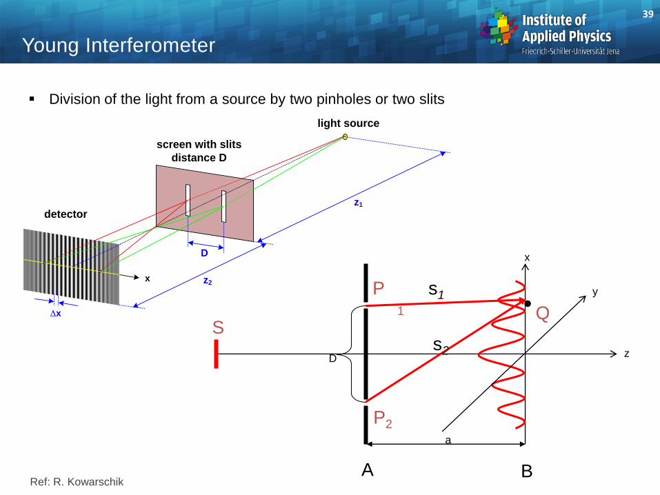
Young Interferometer
Division of the light from a source by two pinholes or two slits
Ref: R. Kowarschik
P1
S
A B
Q
P2
s1
s2
x
y
z D
a
D
z1
z2
light source
screen with slits
distance D
detector
x
x

2
2
0 cos4)(z
xDIxI
D
zx 2
screen with
pinholes
detector
source
z2
region of
interference
z2
x
D
Double Slit Experiment of Young
Young interference experiment:
Ideal case: point source with distance z1, ideal small pinholes with distance D
Interference on a screen in the distance z2 , intensity
Width of fringes

Coherence Measurement with Young Experiment
Typical result of a double-slit experiment according to Young for an Excimer laser to
characterize the coherence
Decay of the contrast with slit distance: direct determination of the transverse coherence
length Lc

Young Experiment with broad Band Source
Realization with movable triple mirror
beam
splitter0
0,1
0,2
0,3
0,4
0,5
0,6
0,7
0,8
0,9
1
-400 -300 -200 -100 0 100 200 300 400
x
contrast
laser
reference
mirror
movable
triple mirror
detector
scan
x
contrast
curve
interferogram
x
y
I(x,y)