metric punch and die - penta-edm.cz - penta trading · pdf filemetric punch and die ......
TRANSCRIPT

Metric Punch and Diewww.awprecision.com

OUR UK SALES & MANUFACTURING FACILITY
AW METRIC PUNCH & DIE CATALOGUE VERSION 2012.A1 REVISED

A C o m p a n y I n t r o d u c t i o n
AW PRECISION is one of Europe’s largest producers of punches, dies and Die Sets. Along with an extensive selection of Tooling Accessories, Kaller® Gas Springs, Cam Units, Urethane and Guide Elements we are your ‘One-Stop’ shop for all your tooling requirements.
AW PRECISION can offer…
Short, consistent delivery times on most standard and non-standard products helping you to maintain a continuous level of production.
Broad range of productsAW Precision’s vast product range simplifies the process of purchasing tools for the increasingly busy tool maker.
NEW PRODUCTS FOR 2012
30° Headed Punches (See pages 61,62)
Dome Headed Punches (See pages 63,64)
Heavy Duty True Strip Retainers (See page 52)
Slug Gripper on dies now available to order (See page 69)
Thread Form Punches & Dies Available (See page 76,77)

C o n t e n t sStandard Punch Blanks 4
Ejector Punch Blanks 5
Standard Punches 6
Standard Ejector Punches 7
Parallel Pilots 8
Point Pilot Punches 9
Angular Parallel Pilot Punches 10
Angular Pilot Punches 11
Plunged Hole Punches 12
Standard Drawing Punches 13
Standard Centre Dowel Punch Blanks 14
Standard Centre Dowel Ejector Punch Blanks 15
Standard Centre Dowel Punches 16
Standard Centre Dowel Ejector Punches 17
Heavy Duty Punch Blanks 18
Heavy Duty Punches 19
Heavy Duty Ejector Punches 20
Countersunk Headed Punches DIN 9861 21
MAP Punches, Punch Quills, Die Bush Clamps 22
Rapid Metric Dies, Ejector Components 23
EDM Die Blanks 24
Round Die Bush Parallel Recess 25
Round Die Bush Taper Recess 26
Die Bushes EDM 27
Die Bushes SPLIT 28
Stripper Bushes 29
Die Bushes Round (Clamping) 30
Die Bushes Shaped (Clamping) 31
Non Standard Punch & Die Shapes 32
Non Standard Punch & Die Shapes 33
Ball Lock Punch Blanks 34
Ball Lock Ejector Punch Blanks 35
Light Duty Ball Lock Punches 36
Heavy Duty Ball Lock Punches 37
Light Duty Ejector Ball Lock Punches 38
Heavy Duty Ejector Ball Lock Punches 39

C o n t e n t sLight Duty Ejector Ball Lock Punches (Point Larger Than Shank) 40
Heavy Duty Ejector Ball Lock Punches (Point Larger Than Shank) 41
Light Duty Ball Lock Punches (Point Larger Than Shank) 42
Heavy Duty Ball Lock Punches (Point Larger Than Shank) 43
Ball Lock Parallel Pilots 44
Ball Lock Angular Parallel Pilots 45
Ball Lock Pilot Points 46
Ball Lock Angular Pilot Points 47
Light Duty Ball Lock Die Blanks 48
Light Duty Ball Lock Dies 49
Ball Lock Retainers 50
Retainer Strippers 51
Heavy Duty True Set Retainers 52
Retainer Strippers 53
Ball Lock Multi Hole Retainer 54
Ball Lock Release Tools 55
Headed Punch Retainer (Shaped) 56
Headed Punch Retainer (Round) 57
ISO Punch Blanks 58
ISO Round / Shaped Punches 59
ISO Round / Shaped Ejector Punches 60
30° Headed Punch Blanks 61
30° Headed Punches Pointed 62
Dome Headed Punch Blanks 63
Dome Headed Punches Pointed 64
Round Dies Counterbore Recess 65
Shaped Dies Counterbore Recess 66
Standard Body Flat Locations 67
Standard Locations 68
Die Alternatives 69
Non Standard Strip Lifters 70
Non Standard Strip Lifters 71
Punch & Die Clearances 72
Tolerance Tables 73
Materials & Coatings 74
BSI ISO 9001:2008 Certificate 75
Thread Form Punches & Dies 76 / 77

4
Standard Punch Blanks
Symbol
Numbers
ShankDia. ø
C
StandardHead
H
Alt.HeadHA
M3 3 4.2 *5.0
M4 4 4.2 *5.0
M5 5 4.2 *5.0
M6 6 5.0
M7 7 5.0
M8 8 5.0
M10 10 5.0
M12 12 5.0
M13 13 5.0
M14 14 5.0
M16 16 5.0
M18 18 5.0
M19 19 6.4 *5.0
M20 20 6.4 *5.0
M22 22 6.4 *5.0
M25 25 6.4 *5.0
M28 28 6.4 *5.0
M30 30 6.4 *5.0
M32 32 6.4 *5.0
M35 35 6.4 *5.0
M40 40 6.4 *5.0
M45 45 6.4 *5.0
Example order:
12 off M10 x 70 lg
Heads 40/55 HRC
L = Standard Overall Lengths 50 - 125 in 5mm increments.
Any alternative dimensions to the above can be specified.
L +0.5−0.0
C+0.000−0.013Cm5
+0.25−0.00
C
H
+3.0 +− 0.25
*HA = 5mm Head Please Specify

5
L = Standard Overall Lengths 50 - 125 in 5mm increments.
Any alternative dimensions to the above can be specified.
Ejector Punch Blanks
Example order:
6 off MPE10 x 70 lg
Ejector components see page 23
Heads 40/55 HRC
Symbol
Numbers
ShankDia.C
StandardHead
H
Alt.HeadHA
PinDia.
P
MPE1 5 4.2 *5.0 0.5
MPE5 5 4.2 *5.0 1.0
MPE6 6 5.0 1.0
MPE7 7 5.0 1.0
MPE8 8 5.0 1.0
MPE10 10 5.0 1.5
MPE12 12 5.0 1.5
MPE13 13 5.0 1.5
MPE16 16 5.0 2.4
MPE18 18 5.0 2.4
MPE19 19 6.4 *5.0 2.4
MPE20 20 6.4 *5.0 2.4
MPE22 22 6.4 *5.0 2.4
MPE25 25 6.4 *5.0 2.4
MPE28 28 6.4 *5.0 2.4
MPE30 30 6.4 *5.0 2.4
MPE32 32 6.4 *5.0 2.4
MPE35 35 6.4 *5.0 2.4
MPE40 40 6.4 *5.0 2.4
L +0.5−0.0
C
P
+0.000−0.013 C m5
+0.25−0.00
C
H
+3.0 +− 0.25
*HA = 5mm Head Please Specify

6
Standard Punches
*HA = 5mm Head Please Specify
Example order:
6 off MT6C 3.5 60 lg 6 off MR28D 20.0 x 14.60 80 lg
Location Flats if required see page 68 NS shapes available see pages 32, 33
Heads 40/55 HRC
+0.25−0.00 12.5
C
H
+3.0
L
3 Lead
Rad
+0.5−0.0
D+0.01−0.00
Cm5
+− 0.25
D
0.5
+0.01−0.00
+0.01−0.00
+0.01−0.00
MTROUND
MRRECTANGLE
ORSQUARE
MFFLATTED
MWOVAL
MLLONG LIFE
90°
0°180°
R270°
A
D
Type A
7
13
19
25
Type B
Type C
Type D
Type AL
ALTERNATIVELENGTH SPECIFY
Symbol Numbers
Round
Rect orSquare
Flatted
Oval
LongLife
ShankDiaC
StandardHead
H
Alt.Head*HA
Min.Piercing
D
MT3 MR3 MF3 MW3 ML3 3 4.2 *5.0 1.5
MT4 MR4 MF4 MW4 ML4 4 4.2 *5.0 1.5
MT5 MR5 MF5 MW5 ML5 5 4.2 *5.0 1.5
MT6 MR6 MF6 MW6 ML6 6 5.0 1.5
MT7 MR7 MF7 MW7 ML7 7 5.0 1.5
MT8 MR8 MF8 MW8 ML8 8 5.0 2.3
MT10 MR10 MF10 MW10 ML10 10 5.0 3.2
MT12 MR12 MF12 MW12 ML12 12 5.0 3.2
MT13 MR13 MF13 MW13 ML13 13 5.0 3.2
MT14 MR14 MF14 MW14 ML14 14 5.0 4.0
MT16 MR16 MF16 MW16 ML16 16 5.0 4.8
MT18 MR18 MF18 MW18 ML18 18 5.0 5.0
MT19 MR19 MF19 MW19 ML19 19 6.4 *5.0 5.0
MT20 MR20 MF20 MW20 ML20 20 6.4 *5.0 5.0
MT22 MR22 MF22 MW22 ML22 22 6.4 *5.0 5.0
MT25 MR25 MF25 MW25 ML25 25 6.4 *5.0 5.0
MT28 MR28 MF28 MW28 ML28 28 6.4 *5.0 5.0
MT30 MR30 MF30 MW30 ML30 30 6.4 *5.0 5.0
MT32 MR32 MF32 MW32 ML32 32 6.4 *5.0 5.0
MT35 MR35 MF35 MW35 ML35 35 6.4 *5.0 5.0
MT40 MR40 MF40 MW40 ML40 40 6.4 *5.0 5.0
MT45 MR45 MF45 MW45 ML45 45 6.4 *5.0 5.0
L = Standard Overall Lengths 50 - 125 in 5mm increments.
Headless Punches available Any alternative dimensions to the above can be specified.

7
Standard Ejector Punches
Example order:
2 off MEF35D 30.0 x 22.0 75 lg. HA = 5 6 off MET13C 9.50 80 lg.
Location Flats if required see page 68 Ejector components see page 23 NS shapes available see pages 32, 33
Heads 40/55 HRC
3 Lead
P
RadH
12.5
+0.25−0.00
C+3.0
Cm5
L +0.5−0.0
D+0.01−0.00 +− 0.25
25
19
13
7
Type A
Type AL
Type D
Type C
Type B
ALTERNATIVELENGTH SPECIFY
*HA = 5mm Head Please Specify
Symbol Numbers
Round
Rect orSquare
Flatted
Oval
LongLife
ShankDia.C
StandardHead
H
Alt.Head*HA
PinHole
P
MinWidthA/D
MET5 MER5 MEF5 MEW5 MEL5 5 4.2 *5.0 1.0 2.5
MET6 MER6 MEF6 MEW6 MEL6 6 5.0 1.0 2.5
MET7 MER7 MEF7 MEW7 MEL7 7 5.0 1.0 3.0
MET8 MER8 MEF8 MEW8 MEL8 8 5.0 1.0 3.0
MET10 MER10 MEF10 MEW10 MEL10 10 5.0 1.5 4.8
MET12 MER12 MEF12 MEW12 MEL12 12 5.0 1.5 4.8
MET13 MER13 MEF13 MEW13 MEL13 13 5.0 1.5 4.8
MET14 MER14 MEF14 MEW14 MEL14 14 5.0 1.5 4.8
MET16 MER16 MEF16 MEW16 MEL16 16 5.0 2.4 5.5
MET18 MER18 MEF18 MEW18 MEL18 18 5.0 2.4 5.5
MET19 MER19 MEF19 MEW19 MEL19 19 6.4 *5.0 2.4 5.5
MET20 MER20 MEF20 MEW20 MEL20 20 6.4 *5.0 2.4 5.5
MET22 MER22 MEF22 MEW22 MEL22 22 6.4 *5.0 2.4 5.5
MET25 MER25 MEF25 MEW25 MEL25 25 6.4 *5.0 2.4 5.5
MET28 MER28 MEF28 MEW28 MEL28 28 6.4 *5.0 2.4 5.5
MET30 MER30 MEF30 MEW30 MEL30 30 6.4 *5.0 2.4 5.5
MET32 MER32 MEF32 MEW32 MEL32 32 6.4 *5.0 2.4 5.5
MET35 MER35 MEF35 MEW35 MEL35 35 6.4 *5.0 2.4 5.5
MET38 MER38 MEF38 MEW38 MEL38 38 6.4 *5.0 2.4 5.5
MET40 MER40 MEF40 MEW40 MEL40 40 6.4 *5.0 2.4 5.5
MET45 MER45 MEF45 MEW45 MEL45 45 6.4 *5.0 2.4 5.5
L = Standard Overall Lengths 50 - 100 in 5mm increments.
Any alternative dimensions to the above can be specified.
D
0.5
+0.01−0.00
+0.01−0.00
+0.01−0.00
METROUND
MERRECTANGLE
ORSQUARE
MEFFLATTED
MEWOVAL
MELLONG LIFE
90°
0°180°
R270°
A
D

8
Parallel Pilots
Example order:
10 off MPP16 x 90 lg
Heads 40/55 HRC
L = Overall lengths up to 125mm
Any alternative dimensions can be specified.
Symbol
No.
ShankDia.C
StandardHead
H
Alt.HeadHA
MPP3 3 4.2 *5.0
MPP4 4 4.2 *5.0
MPP5 5 4.2 *5.0
MPP6 6 5.0
MPP7 7 5.0
MPP8 8 5.0
MPP10 10 5.0
MPP12 12 5.0
MPP13 13 5.0
MPP14 14 5.0
MPP16 16 5.0
MPP18 18 5.0
MPP19 19 6.4 *5.0
MPP20 20 6.4 *5.0
MPP22 22 6.4 *5.0
MPP25 25 6.4 *5.0
MPP28 28 6.4 *5.0
MPP30 30 6.4 *5.0
MPP32 32 6.4 *5.0
MPP35 35 6.4 *5.0
MPP40 40 6.4 *5.0
MPP45 45 6.4 *5.0
Dia C Range Pilot Lead
2.3–6.0 4
6.01–10.0 6
10.01–13.0 8
13.01–18.0 10
18.01–25.0 13
25.01–45.0 16
L +0.5−0.0
C
Pilot Lead
+0.00−0.01
Cm5+0.25−0.00
C
H
+3.0 +− 0.25
*HA = 5mm Head Please Specify

9
Pointed Pilot Punches
Symbol
Numbers
ShankDia.C
StandardHead
H
Alt.HeadHA
PilotDia.D
MP3 3 4.2 *5.0 2.3–2.95
MP4 4 4.2 *5.0 2.3–3.95
MP5 5 4.2 *5.0 2.3–4.95
MP6 6 5.0 2.3–5.95
MP7 7 5.0 3.2–6.95
MP8 8 5.0 3.2–7.95
MP10 10 5.0 3.2–9.95
MP12 12 5.0 5.3–11.95
MP13 13 5.0 6.3–12.95
MP14 14 5.0 6.3–13.95
MP16 16 5.0 9.5–15.95
MP18 18 5.0 9.5–17.95
MP19 19 6.4 *5.0 9.5–18.95
MP20 20 6.4 *5.0 12.0–19.95
MP22 22 6.4 *5.0 15.0–21.95
MP25 25 6.4 *5.0 18.0–24.95
MP28 28 6.4 *5.0 22.0–27.95
MP30 30 6.4 *5.0 25.0–29.95
MP32 32 6.4 *5.0 27.0–31.95
MP35 35 6.4 *5.0 30.0–34.95
MP40 40 6.4 *5.0 33.0–39.95
MP45 45 6.4 *5.0 38.0–44.95
Example order:
12 off MP18C 12.0 90 lg
Heads 40/55 HRC
Dia D Range Pilot Lead
2.3–6.0 4
6.01–10.0 6
10.01–13.0 8
13.01–18.0 10
18.01–25.0 13
25.01–45.0 16
L +0.5−0.0
D+0.00−0.01
3 Lead
Pilot Lead Rad
Cm5
+0.25−0.00H
C+3.0
12.5
+− 0.25
Type B
19
Type C
25
32
Type D
ALTERNATIVELENGTH SPECIFY
Type AL
L = Overall lengths up to 125mm
Any alternative dimensions can be specified.
*HA = 5mm Head Please Specify

10
Angular Parallel Pilot Punches
Example order:
6 off AMPP10 x 100 L = 100 + A
Heads 40/55 HRC
L = Overall lengths up to 125
Any alternative dimensions can be specified.
Symbol
Numbers
ShankDia.C
StandardHead
H
Alt.HeadHA
A
AMPP3 3 4.2 *5.0 6.0
AMPP4 4 4.2 *5.0 6.0
AMPP5 5 4.2 *5.0 8.0
AMPP6 6 5.0 8.0
AMPP7 7 5.0 8.0
AMPP8 8 5.0 8.0
AMPP10 10 5.0 10.0
AMPP12 12 5.0 10.0
AMPP13 13 5.0 15.0
AMPP14 14 5.0 15.0
AMPP16 16 5.0 20.0
AMPP18 18 5.0 20.0
AMPP19 19 6.4 *5.0 25.0
AMPP20 20 6.4 *5.0 25.0
AMPP22 22 6.4 *5.0 25.0
AMPP25 25 6.4 *5.0 30.0
AMPP28 28 6.4 *5.0 30.0
AMPP30 30 6.4 *5.0 30.0
AMPP32 32 6.4 *5.0 30.0
L + A = OVERALL LENGTH
L A+0.5−0.0
C+0.00−0.01
Cm5
+0.25−0.00
C
H
+3.0
*HA = 5mm Head Please Specify

11
Angular Pilot Punches
Symbol
Numbers
ShankDia.C
StandardHead
H
Alt.HeadHA
Pilot Dia
D
A
AMP10 10 5.0 4.5 - 10.0 8
AMP13 13 5.0 6.0 - 13.0 10
AMP16 16 5.0 10.0 - 16.0 15
AMP20 20 6.4 *5.0 13.5 - 20.0 20
AMP25 25 6.4 *5.0 17.5 - 25.0 25
AMP32 32 6.4 *5.0 20.5 - 32.0 30
Example order:
AMP16B 4 off 13.5 x 100
L = 100 + A
Heads 40/55 HRC
L + A = OVERALL LENGTH
Type B
Type C
Type D
B=13A
C=19A
C=25
A
ALTERNATIVELENGTH SPECIFY
A
Type AL
LA
SBR3 Lead
+0.5−0.0
D+0.00−0.01
Cm5
+0.25−0.00H
Rad12.5
C+3.0
BLEND RAD
PILOT LEAD
L = Overall lengths up to 125
Any alternative dimensions can be specified.
*HA = 5mm Head Please Specify

12
Plunged Hole Punches
Symbol
Numbers
ScrewThread
Dia.
A
Dia.C
Dia.D
Dim.L1
StandardHead
H
Alt.HeadHA
Dim.
L
PH2 M2 1.1 3.0 1.65 1.5 4.2 *5.0
SPECIFY
PH2.5 M2.5 1.5 3.0 2.1 2.0 4.2 *5.0
PH3 M3 1.8 3.0 2.55 2.5 4.2 *5.0
PH4 M4 2.3 4.0 3.35 3.0 4.2 *5.0
PH5 M5 3.0 5.0 4.25 3.0 4.2 *5.0
PH6 M6 3.5 6.0 5.1 3.0 5.0
PH8 M8 4.9 8.0 6.85 4.0 5.0
Example order:
6 off PH4 75 lg
Heads 40/55 HRC
#Specify if Angle required instead of Radius
Any alternative dimensions to the above can be specified
1
12.03 LeadL
H
L
Rad
Rad#
12.5
C+3.0
Cm5
A+0.01−0.00
D+0.01−0.01
*HA = 5mm Head Please Specify
13
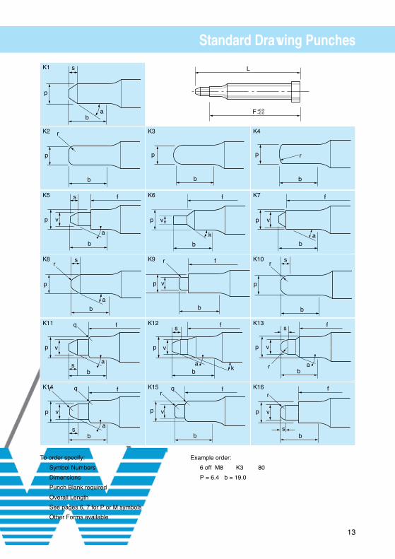
Standard Drawing Punches
Example order:
6 off M8 K3 80
P = 6.4 b = 19.0
To order specify:
Symbol Numbers
Dimensions
Punch Blank required
Overall Length
See pages 6, 7 for P or M symbols
Other Forms available
s
p
ab
r
p
b
s
p v
b
a
f
sr
p
ba
s
fq
b
vp
a
s
fqr
b
vp
a
p
b
f
b
p v
k
fr
b
p v
s f
kb
vp
a
fq
b
vp
r
L
F +0.3−0.0
p
b
r
f
v
ba
p
sr
p
b
s f
v
r ab
p
fr
p v
sb
K1
K2 K3 K4
K5 K6 K7
K8 K9 K10
K13
K16
K12
K15
K11
K14

14
Standard Centre Dowel Punch Blanks
SymbolNumbers
ShankDia. C
LOverall Length
LM10 10 56 63 71 80 90 100 125
LM13 13 56 63 71 80 90 100 125
LM16 16 56 63 71 80 90 100 125
LM20 20 56 63 71 80 90 100 125
LM25 25 56 63 71 80 90 100 125
LM32 32 56 63 71 80 90 100 125
Any alternative dimensions can be specified.
Example order:
6 off LM10 x 80
L +0.5−0.0
C+0.000−0.013Cm5
5 +0.01−0.01
(Dowel not supplied)
C
Ø6mm Dowel
+3.0 +− 0.25
11

15
Standard Centre Dowel Ejector Punch Blanks
Any alternative dimensions can be specified.
Example order:
6 off LME10 x 80
SymbolNumbers
ShankDia. C
LOverall Length
LME10 10 56 63 71 80 90 100 125
LME13 13 56 63 71 80 90 100 125
LME16 16 56 63 71 80 90 100 125
LME20 20 56 63 71 80 90 100 125
LME25 25 56 63 71 80 90 100 125
LME32 32 56 63 71 80 90 100 125
L +0.5−0.0
C+0.000−0.013 Cm5
5 +0.01−0.01
(Dowel not supplied)
C
Ø6mm Dowel
+3.0 +− 0.25
11

16
Standard Centre Dowel Punches
L
3 Lead
+0.5−0.0
D
D
A
D
LMTROUND
LMRRECTANGLE
ORSQUARE
LMFFLATTED
LMWOVAL
LMLLONG LIFE
90°
270°R
180° 0°
+0.01−0.00
+0.01−0.00
+0.01−0.00
Cm55 +0.01
−0.01
Rad12.5
C+3.0
(Dowel not supplied)Ø6mm Dowel
Type A
7
13
19
25
Type B
Type C
Type D
Type AL
ALTERNATIVELENGTH SPECIFY
0.5
11
+− 0.25
L = Overall Standard Lengths 50 up to 125 in 5mm increments
Any alternative dimensions can be specified.
Example order:
6 off LMR32D x 20 x 14.6 x 80
Alternative shapes. See pages 32, 33
Location flats if required see page 68
Symbol Numbers
Round
Rector
Square
Flatted
Oval
LongLife
ShankDiaC
Min.Piercing
D
LMT10 LMR10 LMF10 LMW10 LML10 10 3.2
LMT13 LMR13 LMF13 LMW13 LML13 13 3.2
LMT16 LMR16 LMF16 LMW16 LML16 16 4.8
LMT20 LMR20 LMF20 LMW20 LML20 20 5.0
LMT25 LMR25 LMF25 LMW25 LML25 25 5.0
LMT32 LMR32 LMF32 LMW32 LML32 32 5.0

17
Standard Centre Dowel Ejector Punches
L
3 Lead
+0.5−0.0
D P
D
A
D
LMETROUND
LMERRECTANGLE
ORSQUARE
LMEFFLATTED
LMEWOVAL
LMELLONG LIFE
90°
270°R
180° 0°
+0.01−0.00
+0.01−0.00
+0.01−0.00
Cm5 5 +0.01−0.01
Rad12.5
C+3.0
(Dowel not supplied)Ø6mm Dowel Type A
7
13
19
25
Type B
Type C
Type D
Type AL
ALTERNATIVELENGTH SPECIFY
0.5
+− 0.25
11
Symbol Numbers
Round
Rector
Square
Flatted
Oval
LongLife
ShankDiaC
PinHole
P
Min.WidthA/D
LMET10 LMER10 LMEF10 LMEW10 LMEL10 10 1.5 4.8
LMET13 LMER13 LMEF13 LMEW13 LMEL13 13 1.5 4.8
LMET16 LMER16 LMEF16 LMEW16 LMEL16 16 2.4 5.5
LMET20 LMER20 LMEF20 LMEW20 LMEL20 20 2.4 5.5
LMET25 LMER25 LMEF25 LMEW25 LMEL25 25 2.4 5.5
LMET32 LMER32 LMEF32 LMEW32 LMEL32 32 2.4 5.5
L = Standard Overall Standard Lengths 50 up to 125 in 5mm increments
Any alternative dimensions can be specified.
Example order:
6 off LMR32D x 20 x 14.6 x 80
NS shapes. See pages 32, 33
Location flats if required see page 68

18
Heavy Duty Punch Blanks
Symbol
Numbers
ShankDia.C
d1
HM8 8 8
HM10 10 10
HM12 12 12
HM13 13 13
HM14 14 14
HM16 16 16
HM18 18 18
HM19 19 19
HM20 20 20
HM22 22 22
HM25 25 25
HM28 28 28
HM30 30 30
HM32 32 32
HM35 35 35
HM40 40 40
HM45 45 45
L = Overall Standard Lengths 50 up to 125
Any alternative dimensions can be specified.
Example order:
6 off HM13 x 95 4 off HEM10 x 80
+− 0.25 +− 0.25
m5 m5
HM HEM
Symbol
Numbers
ShankDia.C/d1
Pin Dia P
HEM8 8 1
HEM10 10 1.5
HEM12 12 1.5
HEM13 13 1.5
HEM14 14 1.5
HEM16 16 2.4
HEM18 18 2.4
HEM19 19 2.4
HEM20 20 2.4
HEM22 22 2.4
HEM25 25 2.4
HEM28 28 2.4
HEM30 30 2.4
HEM32 32 2.4
HEM35 35 2.4
HEM40 40 2.4
HEM45 45 2.4

19
Heavy Duty Punches
L
3 Lead
+0.5−0.0
D
D
A
D
HMTROUND
HMRRECTANGLE
ORSQUARE
HMFFLATTED
HMWOVAL
HMLLONG LIFE
90°
270°R
180° 0°
+0.01−0.00
+0.01−0.00
+0.01−0.00
Cm5 8 +0.01−0.01
Rad12.5 Rad10°
1.0
Cd1 +2.5
Type A
7
13
19
25
Type B
Type C
Type D
Type AL
ALTERNATIVELENGTH SPECIFY
0.5
+− 0.25
L = Overall Standard Lengths 50 up to 125
Any alternative dimensions can be specified.
Example Order:
6 off HMT13D x 10.1 x 95
6 off HMF20C x 12.4 x 18 x 90 SF
NS shapes. See pages 32, 33
Location flats & dowel slots if required see page 68
Symbol Numbers
Round
Rector
Square
Flatted
Oval
LongLife
ShankDiaC
d1
Min.Piercing
A/D
HMT8 HMR8 HMF8 HMW8 HML8 8 8 2.3
HMT10 HMR10 HMF10 HMW10 HML10 10 10 1.5
HMT12 HMR12 HMF12 HMW12 HML12 12 12 1.5
HMT13 HMR13 HMF13 HMW13 HML13 13 13 1.5
HMT14 HMR14 HMF14 HMW14 HML14 14 14 1.5
HMT16 HMR16 HMF16 HMW16 HML16 16 16 2.3
HMT18 HMR18 HMF18 HMW18 HML18 18 18 3.2
HMT19 HMR19 HMF19 HMW19 HML19 19 19 3.2
HMT20 HMR20 HMF20 HMW20 HML20 20 20 3.2
HMT22 HMR22 HMF22 HMW22 HML22 22 22 4.0
HMT25 HMR25 HMF25 HMW25 HML25 25 25 4.8
HMT28 HMR28 HMF28 HMW28 HML28 28 28 5.0
HMT30 HMR30 HMF30 HMW30 HML30 30 30 5.0
HMT32 HMR32 HMF32 HMW32 HML32 32 32 5.0
HMT35 HMR35 HMF35 HMW35 HML35 35 35 5.0
HMT40 HMR40 HMF40 HMW40 HML40 40 40 5.0
HMT45 HMR45 HMF45 HMW45 HML45 45 45 5.0

20
Heavy Duty Ejector Punches
L
3 Lead
+0.5−0.0
D
D
A
D
HEMTROUND
HEMRRECTANGLE
ORSQUARE
HEMFFLATTED
HEMWOVAL
HEMLLONG LIFE
90°
270°R
180° 0°
+0.01−0.00
+0.01−0.00
+0.01−0.00
Cm58 +0.01
−0.01
Rad12.5Rad10°
1.0
C d1+2.5
Type A
7
13
19
25
Type B
Type C
Type D
Type AL
ALTERNATIVELENGTH SPECIFY
0.5
+− 0.25
Symbol Numbers
Round
Rector
Square
Flatted
Oval
LongLife
ShankDiaC
d1
Min.Piercing
A/D
HEMT8 HEMR8 HEMF8 HEMW8 HEML8 8 8 2.3
HEMT10 HEMR10 HEMF10 HEMW10 HEML10 10 10 3.2
HEMT12 HEMR12 HEMF12 HEMW12 HEML12 12 12 3.2
HEMT13 HEMR13 HEMF13 HEMW13 HEML13 13 13 3.2
HEMT14 HEMR14 HEMF14 HEMW14 HEML14 14 14 4.0
HEMT16 HEMR16 HEMF16 HEMW16 HEML16 16 16 4.8
HEMT18 HEMR18 HEMF18 HEMW18 HEML18 18 18 5.0
HEMT19 HEMR19 HEMF19 HEMW19 HEML19 19 19 5.0
HEMT20 HEMR20 HEMF20 HEMW20 HEML20 20 20 5.0
HEMT22 HEMR22 HEMF22 HEMW22 HEML22 22 22 5.0
HEMT25 HEMR25 HEMF25 HEMW25 HEML25 25 25 5.0
HEMT28 HEMR28 HEMF28 HEMW28 HEML28 28 28 5.0
HEMT30 HEMR30 HEMF30 HEMW30 HEML30 30 30 5.0
HEMT32 HEMR32 HEMF32 HEMW32 HEML32 32 32 5.0
HEMT35 HEMR35 HEMF35 HEMW35 HEML35 35 35 5.0
HEMT40 HEMR40 HEMF40 HEMW40 HEML40 40 40 5.0
HEMT45 HEMR45 HEMF45 HEMW45 HEML45 45 45 5.0
L = Overall Standard Lengths 50 up to 125
Any alternative dimensions can be specified.
Example Order:
6 off HEMT13D x 10.1 x 95 6 off HEMF20C x 12.4 x 18 x 90 SF
NS shapes. See pages 32, 33
Location flats & dowel slots if required see page 68

21
Countersunk Headed Punches DIN 9861
Shank Size
C
HeadDia.
B
HeadThkE
1.0–1.1 1.8 0.51.15–1.3 2.0 0.51.35–1.5 2.2 0.51.55–1.7 2.5 0.51.75–1.9 2.8 0.51.95–2.0 3.0 0.52.05–2.2 3.2 0.52.25–2.5 3.5 0.52.55–2.95 4.0 0.53.0–3.4 4.5 0.53.5–3.9 5.0 0.54.0–4.4 5.5 0.54.5–4.9 6.0 0.55.0–5.4 6.5 0.55.5–5.9 7.0 0.56.0–6.4 8.0 0.56.5–7.4 9.0 1.07.5–8.4 10.0 1.08.5–9.4 11.0 1.09.5–10.4 12.0 1.010.5–11.4 13.0 1.011.5–12.4 14.0 1.012.5–13.4 15.0 1.013.5–14.4 16.0 1.014.5–15.4 17.0 1.0
Stock lengths up to 100 mm
Any alternative dimensions to the above can be specified
Type DAL
C h6 B 60°
E
DARRECTANGLE
ORSQUARE
A
D
+0.01−0.00
+0.01−0.00
+0.01−0.00
DATROUND
D
25
Type D
19
Type C
13
Type B
ALTERNATIVELENGTH SPECIFY
Type AL
D7
+0.01−0.00
Type A
DALLONG LIFE
R0°180°
90°
270°0.5
DAWOVAL
DAFFLATTED
Example order:
6 off DAT10C x 5.5 x 70 lg 5 off DAW13A x 10.0 x 4.0 x 7.0 lg 10 off DA6 x 100 lg BLANK
NS shapes available – see pages 32, 33
Punch Quills see page 22
DARRECTANGLE
ORSQUARE
A
D
+0.01−0.00
+0.01−0.00
+0.01−0.00
DATROUND
D
25
Type D
19
Type C
13
Type B
ALTERNATIVELENGTH SPECIFY
Type AL
D7
+0.01−0.00
Type A
DALLONG LIFE
R0°180°
90°
270°0.5
DAWOVAL
DAFFLATTED
22
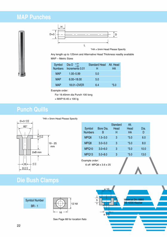
MAP Punches
Punch Quills
Die Bush Clamps
Example order:
For 19.45mm dia Punch 100 long
= MAP19.45 x 100 lg
See Page 68 for location flats
Material Din 6880 BS 4235 Keybar
Example order:
6 off MPQ8 x 3.6 x 25
*HA = 5mm Head Please Specify
Any length up to 125mm and Alternative Head Thickness readily available
MAP – Metric Sizes
SymbolNumbers
Dia DIncrements 0.01
Standard HeadH
Alt. HeadHA
MAP 1.00–5.99 5.0
MAP 6.00–18.00 5.0
MAP 18.01–OVER 6.4 *5.0
+.01–.00
Symbol
Numbers
Bore Dia.
B
StandardHead
H
Alt.HeadHA
Dia.D
MPQ6 1.5–3.0 3 *5.0 6.0
MPQ8 3.0–5.0 3 *5.0 8.0
MPQ10 3.0–6.0 3 *5.0 10.0
MPQ13 5.0–8.0 3 *5.0 13.0
Symbol Number
BR - 1
L
D
H
D+3
*HA = 5mm Head Please Specify
B
19 - 25mm
D+3
D+0.15+0.10
+0.15+0.10
H+0.15−0.00
+0.00−0.25
2xB min
60°
12 h95 8
ø 10
ø 5.516

23
Rapid Metric Dies
Ejector Components - Pins
Ejector Components - Springs
Example order:
6 off RMD13 3.6 x 25 lg
Example order:
30 off ES15
Example order:
30 off EP09
Material H.S.S.
Symbol Numbers Bore Size LHeadless Headed Dia D Dia. C Min Max Land 20–25–32RMD6 RMHD6 6 2 1.2 1.5 3 20–25–32
3 1.51 2.0 3 20–25–32RMD8 RMHD8 8 3 1.5 2.0 3 20–25–32
4 2.01 3.0 3 20–25–32RMD10 RMHD10 10 4 2.0 3.0 5 20–25–32
5 3.01 4.5 5 20–25–32RMD13 RMHD13 13 6 3.0 5.0 5 20–25–32
8 5.01 7.0 5 20–25–32RMD16 RMHD16 16 8 5.0 7.0 5 20–25–32
10 7.01 9.0 5 20–25–32RMD20 RMHD20 20 10 7.0 9.0 8 20–25–32
12 9.0 11.0 8 20–25–3214 11.01 13.0 8 20–25–32
RMD25 RMHD25 25 13 9.0 12.0 8 20–25–3215.5 12.01 14.5 8 20–25–3218 14.51 17.0 8 20–25–32
Symbol O/Dia. Wire Dia. LengthNo. C D L
ES08 2.0 .40 51ES11 2.8 .50 51ES15 3.8 .6 51
Symbol Pin Dia. Head Dia. LengthNo. P C L
EPO2 .51 1.2 51EPO3 .80 1.8 51EPO4 1.0 2.4 51EPO6 1.5 3.0 51EPO9 2.4 4.0 51
Land
Type: RMHDB
CD+3.0
Lead
Land
BType: RMD+0.01−0.00
+0.00−0.25
L +0.50−0.00
5.0 +0.25−0.00
Dm5
Dn5
+0.01−0.00
Land
Type: RMHDB
CD+3.0
Lead
Land
BType: RMD+0.01−0.00
+0.00−0.25
L +0.50−0.00
5.0 +0.25−0.00
Dm5
Dn5
+0.01−0.00
Type: RMD
Type: RMHD
P
L
C
L
D
C

24
EDM Die Blanks
Head Thickness H 5
Length 12 to 32
Symbol Numbers
Dia. D+.015+.010
Dia.
d
MDB5 MDHB5 5
MDB6 MDHB6 6
MDB8 MDHB8 8 1.3
MDB10 MDHB10 10
MDB13 MDHB13 13
MDB16 MDHB16 16
MDB19 MDHB19 19
MDB20 MDHB20 20
MDB22 MDHB22 22 1.6
MDB25 MDHB25 25
MDB28 MDHB28 28
MDB32 MDHB32 32
MDB35 MDHB35 35
MDB38 MDHB38 38
MDB40 MDHB40 40 2.0
MDB42 MDHB42 42
MDB45 MDHB45 45
MDB50 MDHB50 50
+0.25–0
Example order:
12 off MDHB20 25 lg
Alternative Body and Bore size available
Location Flats if required see page 68
Dia d available at 1.0
LengthH
D+3mm
Types: MDHB Types: MDB
D DrilledStart Hole ‘d’

25
Round Die Bush Parallel Recess
Symbol Numbers
Headless
Headed
Dia.D
Bore SizeB
MDP5 MDHP5 5 1.5–3.0
MDP6 MDHP6 6 1.5–4.0
MDP8 MDHP8 8 2.0–5.0
MDP10 MDHP10 10 2.0–6.5
MDP13 MDHP13 13 3.0–8.5
MDP16 MDHP16 16 6.0–10.5
MDP19 MDHP19 19 6.0–11.5
MDP20 MDHP20 20 8.0–13.5
MDP22 MDHP22 22 8.0–15.0
MDP25 MDHP25 25 12.0–17.0
MDP28 MDHP28 28 12.0–22.0
MDP32 MDHP32 32 12.0–26.0
MDP35 MDHP35 35 12.0–28.0
MDP38 MDHP38 38 12.0–30.0
MDP40 MDHP40 40 16.0–32.0
MDP42 MDHP42 42 16.0–33.0
MDP45 MDHP45 45 16.0–34.0
MDP50 MDHP50 50 16.0–36.0
Example order:
12 off MDHP10 5.0 19 lg
Alternative body diameter, overall length and land lengths readily available - see page 69
Type: MDP 12 to 32
Lead
Dm5
B+0.01−0.00
5.0 +0.25−0.00
D+3+0.00−0.25
3.2 Land
Type: MDHP
26
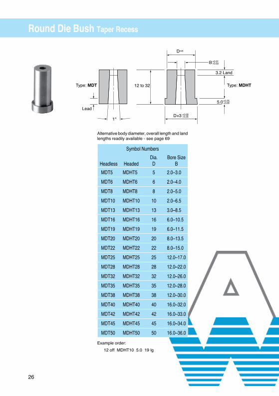
Round Die Bush Taper Recess
Example order:
12 off MDHT10 5.0 19 lg
Alternative body diameter, overall length and land lengths readily available - see page 69
Symbol Numbers
Headless
Headed
Dia.D
Bore SizeB
MDT5 MDHT5 5 2.0–3.0
MDT6 MDHT6 6 2.0–4.0
MDT8 MDHT8 8 2.0–5.0
MDT10 MDHT10 10 2.0–6.5
MDT13 MDHT13 13 3.0–8.5
MDT16 MDHT16 16 6.0–10.5
MDT19 MDHT19 19 6.0–11.5
MDT20 MDHT20 20 8.0–13.5
MDT22 MDHT22 22 8.0–15.0
MDT25 MDHT25 25 12.0–17.0
MDT28 MDHT28 28 12.0–22.0
MDT32 MDHT32 32 12.0–26.0
MDT35 MDHT35 35 12.0–28.0
MDT38 MDHT38 38 12.0–30.0
MDT40 MDHT40 40 16.0–32.0
MDT42 MDHT42 42 16.0–33.0
MDT45 MDHT45 45 16.0–34.0
MDT50 MDHT50 50 16.0–36.0
Type: MDT
Lead
12 to 32
1°
Dm5
B
3.2 Land
Type: MDHT
+0.01−0.00
5.0+0.25−0.00
D+3 +0.00−0.25
27
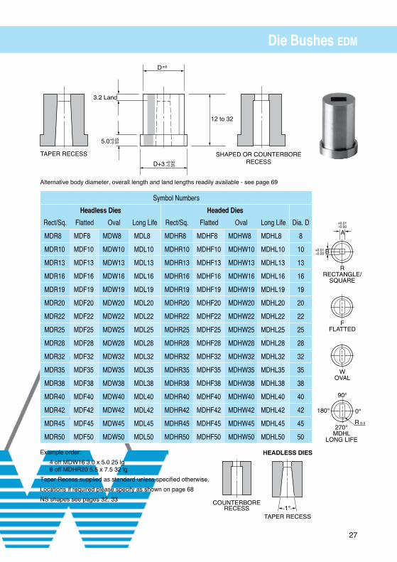
Die Bushes EDM
Symbol Numbers
Headless Dies Headed Dies
Rect/Sq. Flatted Oval Long Life Rect/Sq. Flatted Oval Long Life Dia. D
MDR8 MDF8 MDW8 MDL8 MDHR8 MDHF8 MDHW8 MDHL8 8
MDR10 MDF10 MDW10 MDL10 MDHR10 MDHF10 MDHW10 MDHL10 10
MDR13 MDF13 MDW13 MDL13 MDHR13 MDHF13 MDHW13 MDHL13 13
MDR16 MDF16 MDW16 MDL16 MDHR16 MDHF16 MDHW16 MDHL16 16
MDR19 MDF19 MDW19 MDL19 MDHR19 MDHF19 MDHW19 MDHL19 19
MDR20 MDF20 MDW20 MDL20 MDHR20 MDHF20 MDHW20 MDHL20 20
MDR22 MDF22 MDW22 MDL22 MDHR22 MDHF22 MDHW22 MDHL22 22
MDR25 MDF25 MDW25 MDL25 MDHR25 MDHF25 MDHW25 MDHL25 25
MDR28 MDF28 MDW28 MDL28 MDHR28 MDHF28 MDHW28 MDHL28 28
MDR32 MDF32 MDW32 MDL32 MDHR32 MDHF32 MDHW32 MDHL32 32
MDR35 MDF35 MDW35 MDL35 MDHR35 MDHF35 MDHW35 MDHL35 35
MDR38 MDF38 MDW38 MDL38 MDHR38 MDHF38 MDHW38 MDHL38 38
MDR40 MDF40 MDW40 MDL40 MDHR40 MDHF40 MDHW40 MDHL40 40
MDR42 MDF42 MDW42 MDL42 MDHR42 MDHF42 MDHW42 MDHL42 42
MDR45 MDF45 MDW45 MDL45 MDHR45 MDHF45 MDHW45 MDHL45 45
MDR50 MDF50 MDW50 MDL50 MDHR50 MDHF50 MDHW50 MDHL50 50
Example order:
4 off MDW16 3.0 x 5.0 25 lg 6 off MDHR20 5.5 x 7.5 32 lg
Taper Recess supplied as standard unless specified otherwise.
Locations if required please specify as shown on page 68
NS shapes see pages 32, 33
Alternative body diameter, overall length and land lengths readily available - see page 69
D+3
12 to 32
SHAPED OR COUNTERBORERECESS
3.2 Land
TAPER RECESS+0.00−0.25
Dm5
5.0+0.25−0.00
MDHLLONG LIFE
R
0°180°
90°
270°0.5
WOVAL
FFLATTED
A
B
RRECTANGLE/
SQUARE
+0.01−0.00
+0.01−0.00
COUNTERBORERECESS
HEADLESS DIES
TAPER RECESS1°
28
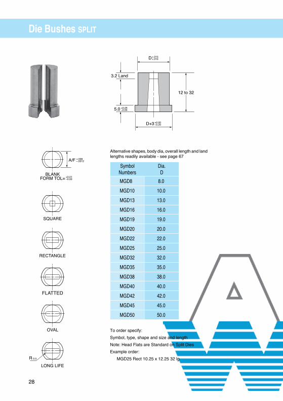
Die Bushes SPLIT
To order specify:
Symbol, type, shape and size and length
Note: Head Flats are Standard on Split Dies
Example order:
MGD25 Rect 10.25 x 12.25 32 lg
Alternative shapes, body dia, overall length and land lengths readily available - see page 67
SymbolNumbers
Dia.D
MGD8 8.0
MGD10 10.0
MGD13 13.0
MGD16 16.0
MGD19 19.0
MGD20 20.0
MGD22 22.0
MGD25 25.0
MGD32 32.0
MGD35 35.0
MGD38 38.0
MGD40 40.0
MGD42 42.0
MGD45 45.0
MGD50 50.0
+.010−.000
+.000−.010
to11—21—4
3—16
Land1—8
D+ 1—8
D+.0004+.0006 D
12 to 32
3.2 Land
+.015+.010
D+3 +0.00−0.25
5.0 +0.25−0.00
A/F +.008−.0012
BLANKFORM TOL= +0.01
−0.00
SQUARE
RECTANGLE
FLATTED
OVAL
LONG LIFE
R 0.5

29
Stripper Bushes
m5
Example order:
6 off MSUR10 3.0 x 4.0 18 lg 8 off MSDW25 8.0 x 12.5 32 lg
If Location Flats are required, then please specify as shown on page 68
Note: Diagonal B must not exceed dia C
Views are from the dia C end
Symbol Numbers BodyDia D
DiaRange B
DiaCHead Down Headless Head Up
MSD*6 MS*6 MSU*6 6 1.5–3.0 3.0
MSD*8 MS*8 MSU*8 8 2.0–4.5 4.5
MSD*10 MS*10 MSU*10 10 3.0–6.0 6.0
MSD*13 MS*13 MSU*13 13 4.0–8.0 8.0
MSD*16 MS*16 MSU*16 16 5.0–9.0 9.0
MSD*19 MS*19 MSU*19 19 7.0–11.0 11.0
MSD*20 MS*20 MSU*20 20 7.0–12.0 12.0
MSD*22 MS*22 MSU*22 22 8.0–14.0 14.0
MSD*25 MS*25 MSU*25 25 8.0–17.0 17.0
MSD*32 MS*32 MSU*32 32 8.0–22.0 22.0
MSD*35 MS*35 MSU*35 35 9.0–25.0 25.0
MSD*38 MS*38 MSU*38 38 9.0–28.0 28.0
Alternative shapes, body dia, overall length and land lengths available.
*insert the shape code
WOVAL
LLONG LIFE
R0°180°
90°
270°0.5
FFLATTED
TROUND
A
B
diagonal B
+.025−.015
+.025−.015
RRECTANGLE
ORSQUARE

30
Die Bushes Round (Clamping)
+0.1−0.1
+0.1−0.1
D - h5
B
B
C
17.5
+0.2+0.332
8.0Land
Lead
4
ø12 h6* Clamp - FMDP
M8
M6
Shims(Not supplied
For extraction
Ø12 - H7
E+0.01−0.01
TYPICAL ASSEMBLYAFTER REGRIND
Cap head screw not supplied
* Die Clamp must be ordered if required.
SymbolNumbers
ø D
ø C
E centres
Bore Sizeø B
SMDP16 16 8 11.5 3 - 7
SMDP20 20 10 13.5 7 - 9
SMDP25 25 17 16 9 - 16
SMDP32 32 22 19.5 16 - 21
SMDP40 40 26 23.5 21 - 25
SMDP50 50 38 28.5 25 - 37
Example Order:
6 off SMDP20 x 7.8
6 off FMDP

31
Die Bushes Shaped (Clamping)
32 +0.2+0.3
17.5
C
Lead
8.0Land
+0.1−0.1
D -h5
A+0.01−0.00
M6
Shims(Not supplied
Ø12 - H7
E +0.01−0.01
TYPICAL ASSEMBLYAFTER REGRIND
4
ø12 h6
* Clamp - FMDP
M8
For extraction
* SMDRRectangleor Square
* SMDWOval
* SMDFFlatted
* SMDLLong Life
R
0°180°
90°
270°0.5
+0.1−0.1B
SymbolNumbers
ø D
ø C
E centres
SMD*16 16 8 11.5
SMD*20 20 10 13.5
SMD*25 25 17 16
SMD*32 32 22 19.5
SMD*40 40 26 23.5
SMD*50 50 38 28.5
* = insert shape code
Example Order: 6 off SMDR20 4.0 x 6.0 6 off FMDP
Cap head screw not supplied
NS shapes available,
see pages 32, 33
* Die Clamp must be ordered if required.

32
Non Standard Punch & Die Shapes
To order Dies please specify the following form dimensions;
Diameter
Length of Land
Shaped, Round or Tapered Recess
Overall Length
Location Flats Standard on split dies only, if required on solid dies please specify as shown on page 67 + 68
Example die order
MDHB16 NS4 25
Y = 6.7 Taper Recess
270°
0°180°
90°
Unless stated otherwise the Y and Z dimensions are equal about the centrelines of Punch or Die Body
z
yr
z
R
r
z
r
y
xw
z
y
z
x
y
z
y
r
R
z
y
z
y
r
z
x/2 y/2
xy
z
x
d
z
y
r
z
z
x
r y
z
y
x
z
x/2
y/2
x
y
y
z
y
r
R
y
z
A
yr
z
y
x
z
y/2
x
y
z
A
DIE VIEW
270°
180° 0°
90°
NS1
NS5
NS9
NS13
NS17
NS2
NS6
NS10
NS14
NS18
NS21
NS3
NS7
NS11
NS15
NS19
NS22
NS4
NS8
NS12
NS16
NS20
33
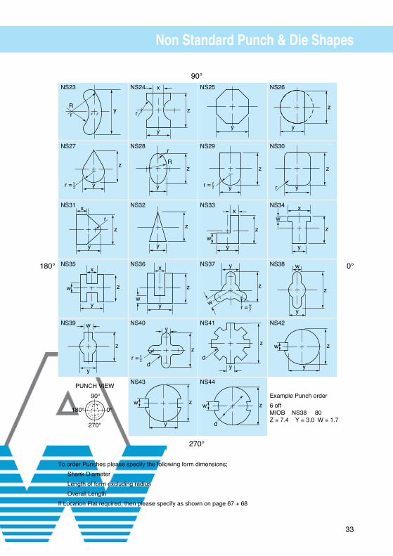
Non Standard Punch & Die Shapes
To order Punches please specify the following form dimensions;
Shank Diameter
Length of form excluding radius
Overall Length
If Location Flat required, then please specify as shown on page 67 + 68
Example Punch order
6 off MIOB NS38 80 Z = 7.4 Y = 3.0 W = 1.7
0°180°
270°
90°
yRr
z
r = yy—2
z
x
y
r
z
x
w
y
z
w
y
z
x
r
y
y
z
r
R
z
y
z
x
wy
z
d
y
r = y—2
zw
y
y
z
yr = y—2
z
x
wy
z
w
y
r = w—2
z
dy
z
d
w
z
y
z
yr
z
xw
y
z
w
y
zw
y
PUNCH VIEW
180° 0°
270°
90°
NS23
NS27
NS31
NS35
NS39
NS24
NS28
NS32
NS36
NS40
NS43
NS25
NS29
NS33
NS37
NS41
NS44
NS26
NS30
NS34
NS38
NS42

34
Ball Lock Punch Blanks
Example order:
10 off LAW16 80 lg
Any alternative dimensions can be specified.
Solid
L = 56 63 71 80 90 100 125
Solid
Light DutySolid
ShankSize
C
Heavy DutySolid
ShankSize
C
LAW 6
LAW 10 HAW 10
LAW 13 HAW 13
LAW 16 HAW 16
LAW 20 HAW 20
LAW 25 HAW 25
LAW 32 HAW 32
HAW 40
L
C g5
+0.5−0.0 L +0.5
−0.0
C g5

35
Ball Lock Ejector Punch Blanks
Example order:
8 off HEW16 80 lg
Any alternative dimensions can be specified.
Ejector
L = 56 63 71 80 90 100 125
Ejector
Light DutyEjector
ShankSize
C
Heavy DutyEjector
ShankSize
C
LEW 6
LEW 10 HEW 10
LEW 13 HEW 13
LEW 16 HEW 16
LEW 20 HEW 20
LEW 25 HEW 25
LEW 32 HEW 32
HEW 40
L
C g5
+0.5−0.0 L +0.5
−0.0
C g5

36
Light Duty Ball Lock Punches
L = Overall standard lengths 50 up to 125
Example order:
6 off LBF13B x 4 x 9 x 60 lg Specify Ball Seat position
NS shapes available see pages 32, 33
0°= Standard Ball Seat Position
Light DutySymbol Numbers
ShankSize
C
Min.Piercing
Dia.D
Min.
WidthALBT LBR LBF LBW LBL
6 6 6 6 6 6 2.5 2.5
10 10 10 10 10 10 3.2 3.2
13 13 13 13 13 13 3.2 3.2
16 16 16 16 16 16 4.8 4.8
20 20 20 20 20 20 5.0 5.0
25 25 25 25 25 25 5.0 5.0
32 32 32 32 32 32 5.0 6.0
38 38 38 38 38 38 8.0 6.0
L
Light Duty Ball Seat
C g5
+0.5−0.0
r
Type A
7
Type B
13
Type C
19
Type D
25
Type AL
ALTERNATIVELENGTH SPECIFY
LBWOVAL
LBTROUND
D+0.01−0.00
D
A
LBRRECTANGLE/
SQUARE
+0.01−0.00
+0.01−0.00
LBLLONG LIFE
90°
0°180°
270°Standard ball
position 0°R 0.5
LBFFLATTED

37
Heavy Duty Ball Lock Punches
Example order:
6 off HBF13B x 4 x 9 x 60 lg Specify Ball Seat position
NS shapes available see pages 32, 33
0°= Standard Ball Seat Position
Heavy DutySymbol Numbers
ShankSize
C
Min.Piercing
Dia.D
Min.
WidthAHBT HBR HBF HBW HBL
10 10 10 10 10 10 3.2 3.2
13 13 13 13 13 13 3.2 3.2
16 16 16 16 16 16 4.8 4.8
20 20 20 20 20 20 5.0 5.0
25 25 25 25 25 25 5.0 5.0
32 32 32 32 32 32 5.0 6.0
40 40 40 40 40 40 8.0 8.0
Heavy Duty Ball Seat
L
C g5
+0.5−0.0
r
Type A
7
Type B
13
Type C
19
Type D
25
Type AL
ALTERNATIVELENGTH SPECIFY
HBWOVAL
HBTROUND
D+0.01−0.00
D
A
HBRRECTANGLE/
SQUARE
+0.01−0.00
+0.01−0.00
HBLLONG LIFE
90°
0°180°
270°Standard
ballposition
0°
R 0.5
HBFFLATTED
L = Overall standard lengths 50 up to 125
38
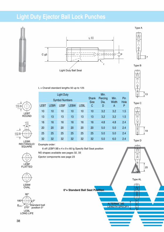
Light Duty Ejector Ball Lock Punches
L = Overall standard lengths 50 up to 125
Example order:
6 off LEBF13B x 4 x 9 x 60 lg Specify Ball Seat position
NS shapes available see pages 32, 33
Ejector components see page 23
0°= Standard Ball Seat Position
Light Duty ShankSize
C
Min.Piercing
Dia.D
Min.
WidthA
Pin
HoleP
Symbol Numbers
LEBT LEBR LEBF LEBW LEBL
10 10 10 10 10 10 3.2 3.2 1.5
13 13 13 13 13 13 3.2 3.2 1.5
16 16 16 16 16 16 4.8 4.8 2.4
20 20 20 20 20 20 5.0 5.0 2.4
25 25 25 25 25 25 5.0 5.0 2.4
32 32 32 32 32 32 5.0 6.0 2.4
PC g5
L
Light Duty Ball Seat
r
+0.5−0.0
7
Type A
Type B
13
Type C
19
Type D
25
Type AL
ALTERNATIVELENGTH SPECIFY
LEBWOVAL
LEBTROUND
D+0.01−0.00
D
A
LEBRRECTANGLE/
SQUARE
+0.01−0.00
+0.01−0.00
LEBLLONG LIFE
90°
0°180°
270°Standard ball
position 0°R 0.5
LEBFFLATTED

39
Heavy Duty Ejector Ball Lock Punches
L = Overall standard lengths 50 up to 125
Example order:
6 off HEBF13B x 4 x 9 x 60 lg Specify Ball Seat position
NS shapes available see pages 32, 33
Ejector components see page 23
Heavy Duty ShankSize
C
Min.Piercing
Dia.D
Min.
WidthA
Pin
HoleP
Symbol Numbers
HEBT HEBR HEBF HEBW HEBL
10 10 10 10 10 10 3.2 3.2 1.5
13 13 13 13 13 13 3.2 3.2 1.5
16 16 16 16 16 16 4.8 4.8 2.4
20 20 20 20 20 20 5.0 5.0 2.4
25 25 25 25 25 25 5.0 5.0 2.4
32 32 32 32 32 32 5.0 6.0 2.4
40 40 40 40 40 40 8.0 8.0 2.4
P C g5
L
Heavy Duty Ball Seat
+0.5−0.0
r
7
Type A
Type B
13
Type C
19
Type D
25
0°= Standard Ball Seat Position
Type AL
ALTERNATIVELENGTH SPECIFY
HEBWOVAL
HEBTROUND
D+0.01−0.00
D
A
HEBRRECTANGLE/
SQUARE
+0.01−0.01
+0.01−0.00
HEBLLONG LIFE
90°
0°180°
270°R 0.5
Standard ball
position 0°
HEBFFLATTED

40
Light Duty Ejector Ball Lock Punches (Point Larger Than Shank)
L
C g5
+0.5−0.0
r
Type B
13
Type C
19
Type D
25
Type AL
ALTERNATIVELENGTH SPECIFY
Symbol Numbers
Light Duty Ejector Point Range
Round
Rect/Square
Flatted
Oval Long Life Shank
Dia. C(min)
A(max)
D
AELT10 AELR10 AELF10 AELW10 AELL10 10 10.00 - 24.00
AELT13 AELR13 AELF13 AELW13 AELL13 13 10.00 - 32.00
AELT16 AELR16 AELF16 AELW16 AELL16 16 10.00 - 38.00
AELT20 AELR20 AELF20 AELW20 AELL20 20 10.00 - 38.00
AELT25 AELR25 AELF25 AELW25 AELL25 25 15.00 - 45.00
AELT32 AELR32 AELF32 AELW32 AELL32 32 15.00 - 45.00
Example order:
AELR16C 8.4 x 21.60 x 80 BS 35°
NS shapes available see pages 32, 33
Ejector components see page 23
L = Overall length 50 up to 125
0°= Standard Ball Seat Position
A
D
AELWOVAL
D +0.01−0.00
AELTROUND
A
D
+0.01−0.01
+0.01−0.00
AELRRECTANGLE
ORSQUARE
Standard ballposition 0°
270°R
90°
180° 0°
AELLLONG LIFE
0.5
A
D
AELFFLATTED

41
Heavy Duty Ejector Ball Lock Punches (Point Larger Than Shank)
L
C g5
+0.5−0.0
r
Type B
13
Type C
19
Type D
25
Type AL
ALTERNATIVELENGTH SPECIFY
Symbol Numbers
Heavy Duty Ejector Point Range
Round
Rect/Square
Flatted
Oval Long Life Shank
Dia. C(min)
A(max)
D
AEHT10 AEHR10 AEHF10 AEHW10 AEHL10 10 10.00 - 24.00
AEHT13 AEHR13 AEHF13 AEHW13 AEHL13 13 10.00 - 32.00
AEHT16 AEHR16 AEHF16 AEHW16 AEHL16 16 10.00 - 38.00
AEHT20 AEHR20 AEHF20 AEHW20 AEHL20 20 10.00 - 38.00
AEHT25 AEHR25 AEHF25 AEHW25 AEHL25 25 15.00 - 45.00
AEHT32 AEHR32 AEHF32 AEHW32 AEHL32 32 15.00 - 45.00
AEHT40 AEHR40 AEHF40 AEHW40 AEHL40 40 15.00 - 50.00
L = Overall length 50 up to 125
Example order:
AEHR16C 8.4 x 21.60 x 80 BS 0°
NS shapes available see pages 32, 33
Ejector components see page 23
0°= Standard Ball Seat Position
A
D
AEHWOVAL
D +0.01−0.00
AEHTROUND
A
D
+0.01−0.01
+0.01−0.00
AEHRRECTANGLE
OR
SQUARE
Standard ballposition 0°
270°R
90°
180° 0°
AEHLLONG LIFE
0.5
A
D
AEHFFLATTED

42
Light Duty Ball Lock Punches (Point Larger Than Shank)
Type B
13
Type C
19
Type D
25
Type AL
ALTERNATIVELENGTH SPECIFY
Symbol Numbers
Light Duty Point Range
Round
Rect/Square
Flatted
Oval Long Life Shank
Dia. C(min)
A(max)
D
ALT10 ALR10 ALF10 ALW10 ALL10 10 5.00 - 24.00
ALT13 ALR13 ALF13 ALW13 ALL13 13 5.00 - 32.00
ALT16 ALR16 ALF16 ALW16 ALL16 16 6.00 - 38.00
ALT20 ALR20 ALF20 ALW20 ALL20 20 8.00 - 38.00
ALT25 ALR25 ALF25 ALW25 ALL25 25 10.00 - 45.00
ALT32 ALR32 ALF32 ALW32 ALL32 32 12.00 - 45.00
L = Overall length 50 up to 125
Example order:
ALL20 C 8.6 x 21.3 x 90 BS 90°
NS shapes available see pages 32, 33
0°= Standard Ball Seat Position
A
D
ALWOVAL
D +0.01−0.00
ALTROUND
A
D
+0.01−0.01
+0.01−0.01
ALRRECTANGLE
ORSQUARE
Standard ballposition 0°
270°R
90°
180° 0°
ALLLONG LIFE
0.5
A
D
ALFFLATTED
L
C g5
+0.5−0.0

43
Heavy Duty Ball Lock Punches (Point Larger Than Shank)
Type B
13
Type C
19
Type D
25
Type AL
ALTERNATIVELENGTH SPECIFY
Symbol Numbers
Heavy Duty Point Range
Round
Rect/Square
Flatted
Oval Long Life Shank
Dia. C(min)
A(max)
D
AHT10 AHR10 AHF10 AHW10 AHL10 10 5.00 - 24.00
AHT13 AHR13 AHF13 AHW13 AHL13 13 5.00 - 32.00
AHT16 AHR16 AHF16 AHW16 AHL16 16 6.00 - 38.00
AHT20 AHR20 AHF20 AHW20 AHL20 20 8.00 - 38.00
AHT25 AHR25 AHF25 AHW25 AHL25 25 10.00 - 45.00
AHT32 AHR32 AHF32 AHW32 AHL32 32 12.00 - 45.00
AHT40 AHR40 AHF40 AHW40 AHL40 40 15.00 - 50.00
L = Overall length 50 up to 125
Example order:
AHR16C 8.4 x 21.60 x 80
NS shapes available see pages 32, 33
0°= Standard Ball Seat Position
L
C g5
+0.5−0.0
A
D
AHWOVAL
D +0.01−0.00
AHTROUND
A
D
+0.01−0.01
+0.01−0.00
AHRRECTANGLE
ORSQUARE
Standard ballposition 0°
270°R
90°
180° 0°
AHLLONG LIFE
0.5
A
D
AHFFLATTED
44
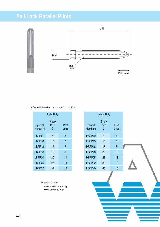
Ball Lock Parallel Pilots
Light Duty Heavy Duty
Symbol
Numbers
ShankSize
C
PilotLead
Symbol
Numbers
ShankSize
C
PilotLead
LBPP6 6 4 HBPP10 10 6
LBPP10 10 6 HBPP13 13 8
LBPP13 13 8 HBPP16 16 8
LBPP16 16 8 HBPP20 20 10
LBPP20 20 10 HBPP25 25 13
LBPP25 25 13 HBPP32 32 13
LBPP32 32 13 HBPP40 40 16
L = Overall Standard Lengths 50 up to 125
Example Order:
6 off HBPP13 x 60 lg 6 off LBPP 20 x 84
BallSeat
C g5
Pilot Lead
L+0.5−0.0

45
Ball Lock Angular Parallel Pilots
Example Order:
6 off LBAP10 x 90 L = 90 + A 4 off HBAP32 x 110
L + A = OVERALL LENGTH
Light Duty Ball Seat Heavy Duty Ball Seat
Symbol
Numbers
ShankDiaC
A
Symbol
Numbers
ShankDiaC
A
LBAP10 10 8 HBAP10 10 8
LBAP13 13 10 HBAP13 13 10
LBAP16 16 15 HBAP16 16 15
LBAP20 20 20 HBAP20 20 20
LBAP25 25 25 HBAP25 25 25
LBAP32 32 30 HBAP32 32 30
LBAP38 38 35 HBAP40 40 40
LA
C g5
Ball Seat
BLEND RAD
Pilot Lead
20°
+0.5−0.0
L = Overall Standard Lengths 50 up to 125
THIS RANGE TO BE DISCONTINUED DECEMBER 2012
PLEASE SEE PAGE 47 FOR REPLACEMENT ARTICLE

46
Ball Lock Pilot Points
L
C g5
Ball Seat
D
Pilot Lead
+0.00−0.01
Type B
19
Type C
25
Type D
32
Type AL
ALTERNATIVELENGTH SPECIFY
+0.5−0.0
r
L = Overall Standard Lengths 56 up to 125
Example Order:
6 off HBP13B x 9 x 60 lg
PilotLead
Dia RangeD
4 2.3 - 6.0
6 6.01 - 10.0
8 10.01 - 13.0
10 13.01 - 18.0
13 18.01 - 25.0
16 25.01 - 40.0
Light Duty Heavy Duty
Symbol
Numbers
ShankSize
C
Symbol
Numbers
ShankSize
C
LBP6 6 HBP10 10
LBP10 10 HBP13 13
LBP13 13 HBP16 16
LBP16 16 HBP20 20
LBP20 20 HBP25 25
LBP25 25 HBP32 32
LBP32 32 HBP40 40
LBP38 38

47
Ball Lock Angular Pilot PointsL + A = OVERALL LENGTH
C g5
Ball Seat
+0.01−0.00
A L
BLEND RAD 20°
Pilot Lead
B=13
Type B
A
C=19
Type C
A
D=25
Type D
A
Type AL
A
ALTERNATIVELENGTH SPECIFY
+0.5−0.0
r
C g5
Ball Seat
+0.01−0.00
A L
BLEND RAD 20°
Pilot Lead
B=13
Type B
A
C=19
Type C
A
D=25
Type D
A
Type AL
A
ALTERNATIVELENGTH SPECIFY
+0.5−0.0
Example Order:
6 off LBAPP13D X 10.1 X 80 L = 80 + A
6 off HBAPP16C x 15.5 x 100 L = 100 + A
L = Overall length from 56-125
Heavy Duty Ball Seat
Symbol
Numbers
Size
C
PointDiaD
A
HBAPP10 10 5.0 - 10.0 8
HBAPP13 13 9.0 - 13.0 10
HBAPP16 16 12.0 - 16.0 15
HBAPP20 20 15.0 - 20.0 20
HBAPP25 25 19.0 - 25.0 25
HBAPP32 32 24.0 - 32.0 30
HBAPP40 40 30.0 - 40.0 40
Light Duty Ball Seat
Symbol
Numbers
Size
C
PointDiaD
A
LBAPP10 10 5.0 - 10.0 8
LBAPP13 13 9.0 - 13.0 10
LBAPP16 16 12.0 - 16.0 15
LBAPP20 20 15.0 - 20.0 20
LBAPP25 25 19.0 - 25.0 25
LBAPP32 32 24.0 - 32.0 30
LBAPP38 38 24.0 - 38.0 35

48
Light Duty Ball Lock Die Blanks
Example Order:
6 off LBDB13 x 32
Symbol Numbers dia. D E ø StartHole
LBDB13 13 1.6
LBDB16 16 1.6
LBDB20 20 1.6
LBDB25 25 2.0
LBDB32 32 2.0
D-g5
E Ø Start Hole
32 +0.5−0.0
49
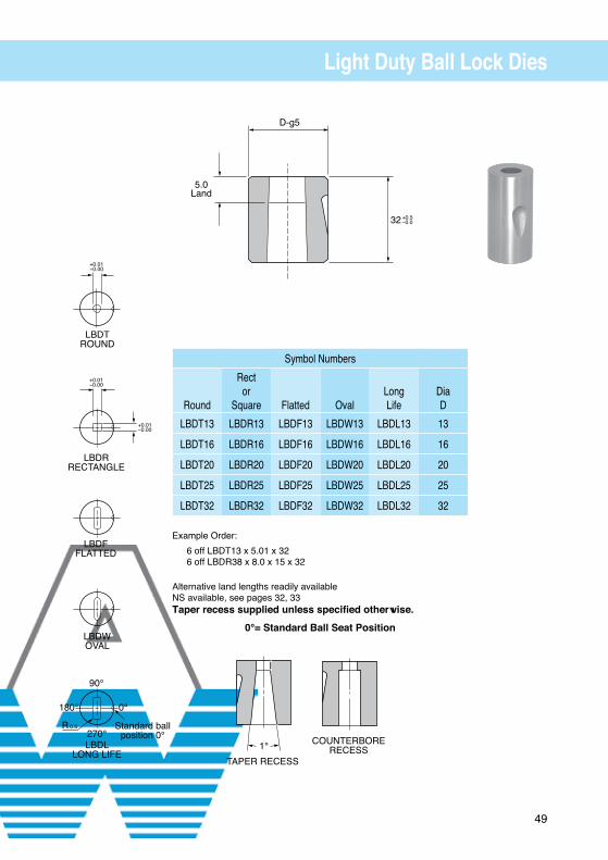
Light Duty Ball Lock Dies
Symbol Numbers
Round
Rector
Square
Flatted
Oval
LongLife
DiaD
LBDT13 LBDR13 LBDF13 LBDW13 LBDL13 13
LBDT16 LBDR16 LBDF16 LBDW16 LBDL16 16
LBDT20 LBDR20 LBDF20 LBDW20 LBDL20 20
LBDT25 LBDR25 LBDF25 LBDW25 LBDL25 25
LBDT32 LBDR32 LBDF32 LBDW32 LBDL32 32
Example Order:
6 off LBDT13 x 5.01 x 32 6 off LBDR38 x 8.0 x 15 x 32
Alternative land lengths readily available NS available, see pages 32, 33 Taper recess supplied unless specified otherwise.
0°= Standard Ball Seat Position

50
Ball Lock Retainers
Example order:
5 off AWH-13
Light Duty
SymbolNumbers
ShankDia. C
E
G
R
H
J
K
ScrewSize
AWL-06 06 23.000 11.10 8.0 19.00 9.00 8.00 M6
AWL-10 10 26.924 11.12 9.5 19.05 7.50 9.00 M8
AWL-13 13 29.972 14.27 12.7 19.05 6.50 12.00 M8
AWL-16 16 31.750 15.87 14.3 19.05 6.00 13.50 M8
AWL-20 20 33.528 17.47 17.5 19.05 5.00 16.50 M10
AWL-25 25 40.640 19.84 22.2 23.82 7.00 22.00 M12
AWL-32 32 40.640 19.84 22.2 23.82 7.00 22.00 M12
Heavy Duty
SymbolNumbers
ShankDia.C
E
G
R
H
J
K
ScrewSize
AWH-10 10 26.924 11.12 9.5 19.05 7.50 9.00 M8
AWH-13 13 29.972 14.27 12.7 19.05 6.50 12.00 M8
AWH-16 16 31.750 15.87 14.3 19.05 6.00 13.50 M8
AWH-20 20 33.528 17.47 17.5 19.05 5.00 16.50 M10
AWH-25 25 40.640 19.84 22.2 23.82 7.00 22.00 M12
AWH-32 32 40.640 19.84 22.2 23.82 7.00 22.00 M12
AWH-40 40 43.993 24.00 26.00 27.00 10.00 26.00 M12
R K
6.3AWL = 32
C
AWH = 41
J
EH
G G
Manufactured under Patent No.’s 0351395, 5357835 International Patents Pending

51
Retainer Plate D R EAWR-10 10 13 28AWR-13 13 15.5 31AWR-16 16 18 32.9AWR-20 20 20.5 34.8AWR-25 25 24 39.8AWR-32 32 31 41.3AWR-40 40 36 45
Set consists of: Retaining Plate and M8 x 20 Socket Head Cap Screw.
StripperCatalog Number
PunchShank
PressFit D3
d4
L
d3
D2
b
AWS10-44 10 9.75 18 43 21 1.6 6AWS10-54 10 9.75 18 52 21 1.6 6AWS10-64 10 9.75 18 63 21 1.6 6AWS10-74 10 9.75 18 72 21 1.6 6AWS13-44 13 12.75 23 43 26 3.0 6AWS13-54 13 12.75 23 52 26 3.0 6AWS13-64 13 12.75 23 63 26 3.0 6AWS13-74 13 12.75 23 72 26 3.0 6AWS16-44 16 15.75 28 43 31 3.0 6AWS16-54 16 15.75 28 52 31 3.0 6AWS16-64 16 15.75 28 63 31 3.0 6AWS16-74 16 15.75 28 72 31 3.0 6AWS20-44 20 19.75 33 43 36 3.0 7AWS20-54 20 19.75 33 52 36 3.0 7AWS20-64 20 19.75 33 63 36 3.0 7AWS20-74 20 19.75 33 72 36 3.0 7AWS25-44 25 24.75 40 43 43 3.0 7AWS25-54 25 24.75 40 52 43 3.0 7AWS25-64 25 24.75 40 63 43 3.0 7AWS25-74 25 24.75 40 72 43 3.0 7AWS32-44 32 31.70 50 43 55 3.0 7AWS32-54 32 31.70 50 52 55 3.0 7AWS32-64 32 31.70 50 63 55 3.0 7AWS32-74 32 31.70 50 72 55 3.0 7AWS40-44 40 39.70 60 43 65 3.0 8AWS40-64 40 39.70 60 63 65 3.0 8
Urethane Hardness 90-95 Shore A
Retainer Strippers
bD2
d4
L
3
d3
D3
5 10
E
R 8R 4.50
R
D
11.5

52
Heavy Duty True Set Retainers
41.0
6.3
POSITIVE RETENTIONSET SCREW
IN-LINEDOWELSLIP-FIT
M4 x .7
K
ø L
SCREW
G
E
M°
øD
SymbolNumbers øD
øL
E
G
K
M
ScrewSize
In-LineDowel
ARH-10 10 26.924 11.12 9.5 19.05 7.50 9.00 M8
ARH-13 13 29.972 14.27 12.7 19.05 6.50 12.00 M8
ARH-16 16 31.750 15.87 14.3 19.05 6.00 13.50 M8
ARH-20 20 33.528 17.47 17.5 19.05 5.00 16.50 M10
ARH-25 25 40.640 19.84 22.2 23.82 7.00 22.00 M12
ARH-32 32 40.640 19.84 22.2 23.82 7.00 22.00 M12
ARH-40 40 43.993 24.00 26.00 27.00 10.00 26.00 M12
Example order:
10 off ARH-16
International Patents Pending
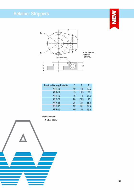
53
Retainer Backing Plate Set D R EARR-10 10 13 22.5ARR-13 13 15.5 25ARR-16 16 18 27.5ARR-20 20 20.5 30ARR-25 25 24 35.5ARR-32 32 31 37.5ARR-40 40 36 42.3
Retainer Strippers
R
DE
10
M4 SCREW
5
InternationalPatentsPending.
Example order:
4 off ARR-25

54
Light Duty Heavy Duty
AWML = 32AWMH = 41
Ball Lock Multi Hole Retainer
SymbolNumber
D
A
B
T
SymbolNumber
D
A
B
T
AWML6 6 12 6 32 AWMH10 10 15 10 41
AWML10 10 13 8 32 AWMH13 13 17 12 41
AWML13 13 13 8 32 AWMH16 16 17 12 41
AWML16 16 13 8 32 AWMH20 20 17 12 41
AWML20 20 13 8 32 AWMH25 25 17 12 41
AWML25 25 13 8 32 AWMH32 32 17 12 41
AWML32 32 13 8 32 AWMH40 40 17 12 41
PunchShape
Class BallHole
RadialTolerance
Standard Tolerances
Outside edges ± 0.5mm
RoundShaped
RF
± 5° ± 0°5'
Dowel Hole Locations ± 0.01mm
Screw Hole Locations ± 0.1mm
Component Hole Locations ± 0.01mm
Class R Supplied unless otherwise specified
Example Order:
AWML10F (Light Duty Shaped punch holder) To Customer Drawing
Specify radial location in degreesanti clockwise from 0°
BBall Dia
A90°
0°
270°
180°
D
T
Drill Clearance For BallRelease Tool
6.3ref

55
Ball Lock Release Tools
Example order:
6 off 818046
Ball Lock Angle Tool
Order Code: 818038
Ball Lock Straight Tool
Order Code: 818046
Ball Lock Threaded Tool
Order Code: 269999

56
Headed Punch Retainer (Shaped)
Example order:
12 off HHS13
12 off BOP13
SymbolNumbers
C
L
W
D
G
H
R
S
E
K
J
ScrewSize
HHS10 10 44.5 43.7 5.0 11.12 19.0 9.5 12.0 26.925 9.0 7.5 M8
HHS13 13 50.8 50.0 6.5 14.27 19.0 12.7 15.2 29.970 12.0 6.5 M8
HHS16 16 54.0 53.2 8.0 15.87 19.0 14.3 16.8 31.750 13.5 6.0 M8
HHS20 20 60.3 59.6 10.0 17.47 19.0 17.5 20.0 33.530 16.5 5.0 M10
HHS25 25 69.9 69.1 12.5 19.84 23.8 22.2 24.7 40.640 22.0 7.0 M12
HHS32 32 69.9 69.1 16.0 19.84 23.8 22.2 24.7 40.640 22.0 7.0 M12
BackingPlate
ød1
BOP10 10
BOP13 10
BOP16 10
BOP20 12
BOP25 14
BOP32 14
BOP (Backing Plate)
5.0
ød1 ø6.2 ø6.2
R
K
DøC G5
Finish ø6.0 Dowel ø5.8 (2)
J
H
+0.013−0.013
G
W
+0.13−0.13 G +0.13
−0.13
E
M8 Tapped Hole
+0.01
29°
−0.01
S
L+0.13−0.13
+0.013−0.013
5 +0.05−0.05
25
TO SUIT A 5MM PUNCH HEAD ONLYBOP SOLD SEPARATELY
57
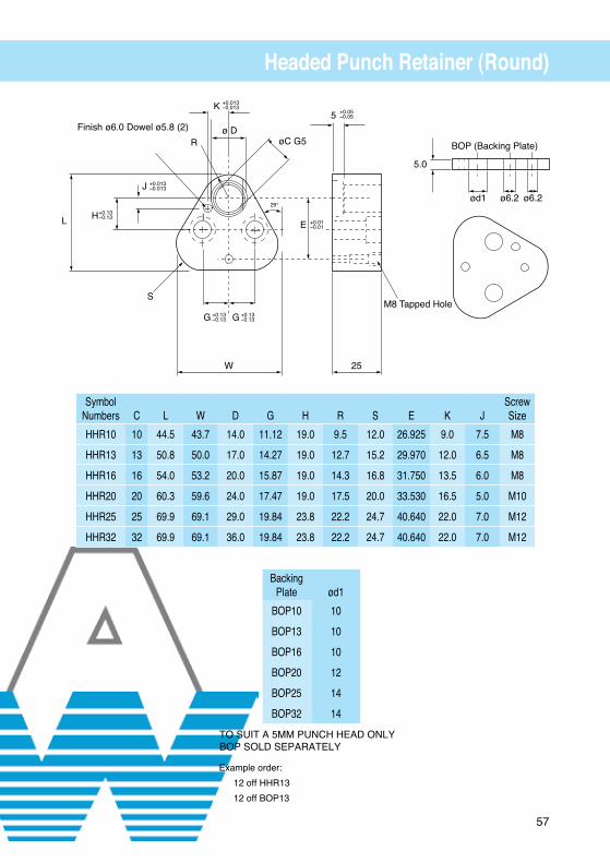
Headed Punch Retainer (Round)
Example order:
12 off HHR13
12 off BOP13
SymbolNumbers
C
L
W
D
G
H
R
S
E
K
J
ScrewSize
HHR10 10 44.5 43.7 14.0 11.12 19.0 9.5 12.0 26.925 9.0 7.5 M8
HHR13 13 50.8 50.0 17.0 14.27 19.0 12.7 15.2 29.970 12.0 6.5 M8
HHR16 16 54.0 53.2 20.0 15.87 19.0 14.3 16.8 31.750 13.5 6.0 M8
HHR20 20 60.3 59.6 24.0 17.47 19.0 17.5 20.0 33.530 16.5 5.0 M10
HHR25 25 69.9 69.1 29.0 19.84 23.8 22.2 24.7 40.640 22.0 7.0 M12
HHR32 32 69.9 69.1 36.0 19.84 23.8 22.2 24.7 40.640 22.0 7.0 M12
BackingPlate
ød1
BOP10 10
BOP13 10
BOP16 10
BOP20 12
BOP25 14
BOP32 14
BOP (Backing Plate)
5.0
ød1 ø6.2 ø6.2
R
K
ø DøC G5
Finish ø6.0 Dowel ø5.8 (2)
J
H
+0.013−0.013
G
W
+0.13−0.13 G +0.13
−0.13
E
M8 Tapped Hole
+0.01
29°
−0.01
S
L+0.13−0.13
+0.013−0.013
5 +0.05−0.05
25
TO SUIT A 5MM PUNCH HEAD ONLYBOP SOLD SEPARATELY

58
ISO Punch Blanks
Alternative sizes on request
Example order:
6 off PB5 x 71
6 off PB16 x 80
ISO 8020
Material M2
Heads 45 ± 5 RC
Shank 60/63 RC Any alternative dimensions can be specified.
SymbolNumbers
ShankDia. C
Head DiaC1
LOverall Length
50 56 60 63 71 80 90 100 125
PB4 4 7 * * * * * * *PB5 5 8 * * * * * * * *PB6 6 9 * * * * * * * *PB8 8 11 * * * * * * * * *PB10 10 13 * * * * * * * * *PB13 13 16 * * * * * * * * *PB16 16 19 * * * * * * * * *PB20 20 23 * * * * * * * * *PB25 25 28 * * * * * * * * *PB32 32 35 * * * * * * * * *
C1 +0.00−0.25
R 0.25
5 +0.25−0.00
C -m5
L +0.5−0.0

59
ISO Round / Shaped Punches
L
D
L2 specify
3 LeadC -m5
+0.5−0.0
L1+1.5−0.0
5 +0.25−0.00
C1+0.00−0.25
R 0.25
PTROUND
PRRECTANGLE
PFFLATTED
PWOVAL PL
LONG LIFE
90°
0°
270°
180°
R
A+0.01−0.00 A+0.01
−0.00
D+0.01−0.00
0.5
Example order:
6 off PT5 x 3.08 71 6 off PW16 x 12 x 8 x 80 L2 = 25
Non standard point lengths should be specified as
eg: PW16(35) 12 x 8 x 80NS shapes available see pages 32, 33 For dowel & location flats see page 68
ISO 8020
Material M2
Heads 45 + 5 RC
Shank 60/63 RC Any alternative dimensions can be specified.
Location flats if required see page 68, 69
Symbol NumbersShankDia.C
HeadDiaC1
MinPierce
D
LOverall Length
L1std
L2Alt
Round
Rect orSquare
Oval
Flatted
LongLife 50 56 60 63 71 80 90 100 125
PT4 PR4 PW4 PF4 PL4 4 7 2.3 * * * * * * * 16
SPECIFY
PT5 PR5 PW5 PF5 PL5 5 8 2.3 * * * * * * * * 16
PT6 PR6 PW6 PF6 PL6 6 9 2.3 * * * * * * * * 16
PT8 PR8 PW8 PF8 PL8 8 11 3.0 * * * * * * * * 20
PT10 PR10 PW10 PF10 PL10 10 13 4.8 * * * * * * * * 20
PT13 PR13 PW13 PF13 PL13 13 16 4.8 * * * * * * * * 25
PT16 PR16 PW16 PF16 PL16 16 19 5.5 * * * * * * * * 25
PT20 PR20 PW20 PF20 PL20 20 23 5.5 * * * * * * * * 25
PT25 PR25 PW25 PF25 PL25 25 28 5.5 * * * * * * * * 25
PT32 PR32 PW32 PF32 PL32 32 35 5.5 * * * * * * * 32

60
L
DP
L2 specify
3 LeadC -m5
+0.5−0.0
L1+1.5−0.0
5 +0.25−0.00
C1+0.00−0.25
R 0.25
D+0.01−0.01
A
PETROUND
PERRECTANGLE
PEFFLATTED
PEWOVAL PEL
LONG LIFE
90°
0°
270°R 0.5
180°
+0.01−0.00 A+0.01
−0.00
ISO Round / Shaped Ejector Punches
Example order:
6 off PET5 x 3.08 71
Non standard point lengths should be specified as
6 off PEW16 L2 = 26 12 x 8 x 80 eg: PEW16 L2 = 35 12 x 8 x 80
NS shapes available see pages 32, 33 For dowel & location flats see page 68
ISO 8020
Material M2
Heads 45 + 5 RC
Shank 60/63 RC Any alternative dimensions can be specified.
Location flats if required see page 66
Symbol NumbersShankDia.C
HeadDiaC1
PinDiaP
MinPierce
D
LOverall Length
L1std
L2Alt
Round
Rect orSquare
Oval
Flatted
LongLife 50 56 60 63 71 80 90 100
PET5 PER5 PEW5 PEF5 PEL5 5 8 1.0 2.5 * * * * * * * * 16
SPECIFY
PET6 PER6 PEW6 PEF6 PEL6 6 9 1.0 2.5 * * * * * * * * 16
PET8 PER8 PEW8 PEF8 PEL8 8 11 1.0 3.0 * * * * * * * * 20
PET10 PER10 PEW10 PEF10 PEL10 10 13 1.5 4.8 * * * * * * * * 20
PET13 PER13 PEW13 PEF13 PEL13 13 16 1.5 4.8 * * * * * * * * 25
PET16 PER16 PEW16 PEF16 PEL16 16 19 2.4 5.5 * * * * * * * * 25
PET20 PER20 PEW20 PEF20 PEL20 20 23 2.4 5.5 * * * * * * * * 25
PET25 PER25 PEW25 PEF25 PEL25 25 28 2.4 5.5 * * * * * * * * 25
PET32 PER32 PEW32 PEF32 PEL32 32 35 2.4 5.5 * * * * * * * * 32
61
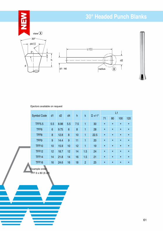
Symbol Code d1 d2 d4 h k α +/-1°L1
71 80 100 120
TFF5.5 5.5 8.98 5.5 7.5 1 30 * * * *TFF6 6 9.75 6 8 1 28 * * * *TFF8 8 12.8 8 10 1 22.5 * * * *TFF9 9 14.4 9 11 1 20 * * * *
TFF10 10 15.9 10 12 1 19 * * * *TFF12 12 18.7 12 14 1.5 24 * * * *TFF14 14 21.8 14 16 1.5 21 * * * *TFF16 16 24.6 16 18 2 25 * * * *
30° Headed Punch Blanks
Example order:
TFF 6 x 80 (6 off)
L1
d2
+0.5−0.0
d1 h6 radiusd
d4
30º
view
+0.0−0.3
k
h
Ejectors available on request

62
Symbol Code d3 d2 d4 h k α +/-1°L1 L2
71 80 100 120 13 19 25
TFP5.5 5.5 8.98 5.5 7.5 1 30 * * * * * * *TFP6 6 9.75 6 8 1 28 * * * * * * *TFP8 8 12.8 8 10 1 22.5 * * * * * * *TFP9 9 14.4 9 11 1 20 * * * * * * *
TFP10 10 15.9 10 12 1 19 * * * * * * *TFP12 12 18.7 12 14 1.5 24 * * * * * * *TFP14 14 21.8 14 16 1.5 21 * * * * * * *TFP16 16 24.6 16 18 2 25 * * * * * * *
30° Headed Punches Pointed
Example order:
TFP 6 (13) 4.2 x 100 (6 off)
L1L2
R13
d2
+0.5−0.0
d1 h6d3 h6 d
d4
30º
view
+0.0−0.3
k
h
Ejectors available on request
63
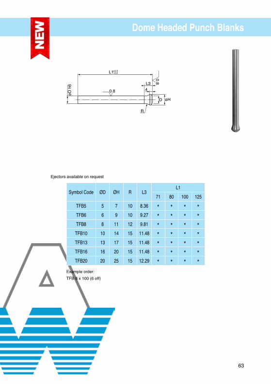
Symbol Code ØD ØH R L3L1
71 80 100 125
TFB5 5 7 10 8.36 * * * *TFB6 6 9 10 9.27 * * * *TFB8 8 11 12 9.81 * * * *
TFB10 10 14 15 11.48 * * * *TFB13 13 17 15 11.48 * * * *TFB16 16 20 15 11.48 * * * *TFB20 20 25 15 12.29 * * * *
Dome Headed Punch Blanks
Example order:
TFB 8 x 100 (6 off)
L1
R
D
4L3
øH
0.8
øD h
6+0.5−0.0
0.8
Ejectors available on request

64
Symbol Code ØD ØH ØP R L3L2 L1
10 13 16 20 25 71 80 100 125
TFS5 5 7 0.8 - 4.9 10 8.36 * * * * * * * * *TFS6 6 9 1.5 - 5.9 10 9.27 * * * * * * * * *TFS8 8 11 2.5 - 7.9 12 9.81 * * * * * * * * *
TFS10 10 14 4.5 - 9.9 15 11.48 * * * * * * * * *TFS13 13 17 6.5 - 12.9 15 11.48 * * * * * * * *TFS16 16 20 9.5 - 15.9 15 11.48 * * * * * * * *TFS20 20 25 12.5 - 19.9 15 12.29 * * * * * * *
Dome Headed Punches Pointed
Example order:
TFS 6 (13) 4.2 x 100 (6 off)
L1
R
D
4L3
øH
0.8
øD h6 øP
+0.5−0.0
L2+0.4−0.4 =h
60.8
r
Ejectors available on request

65
Round Dies Counterbore Recess
Example Order:
1 off DDP10 x 6.1 x 30
1 off DDHP10 x 6.1 x 30
D n5
Lead
Type DDPL
Land
D m5
øB
Type DDHP+0.5−0.0
5
R
+0.25−0.00
D+3+0.00−0.25
ISO 8977
For dowel & location flats, see page 68
Symbol Numbers LOverall Length
Headless
HeadedD Dia
m5
LandR
Maxø BH8 19 20 25 28 30 32 35 40
DDP8 DDHP8 8 3 4.0 1.60 - 3.20 * * * * * * *DDP10 DDHP10 10 3 5.8 1.60 - 5.00 * * * * * * *DDP13 DDHP13 13 3 8.0 3.00 - 7.00 * * * * * * *DDP16 DDHP16 16 5 9.5 3.00 - 8.80 * * * * * * *DDP20 DDHP20 20 5 11.9 3.00 - 11.00 * * * * * * *DDP22 DDHP22 22 5 14.7 3.00 - 14.00 * * * * * * *DDP25 DDHP25 25 5 17.4 3.00 - 17.00 * * * * * * *DDP32 DDHP32 32 7 20.6 3.00 - 20.00 * * * * * * *DDP38 DDHP38 38 7 27.0 3.00 - 26.00 * * * * * * *DDP45 DDHP45 45 7 36.0 3.00 - 35.00 * * * * * * *DDP50 DDHP50 50 7 41.0 3.00 - 40.00 * * * * * * *

66
Shaped Dies Counterbore Recess
Example Order:
1 off DDR10 x 6.1 x 5.1 x 20
1 off DDHW20 x 9.1 x 5.2 x 32
FFLATTED
RRECTANGLE/
SQURE
+0.01−0.00
+0.01−0.00
WOVAL
R 0.5
90°
0°
270°L
LONGLIFE
180°
D n5
Lead
Type DDL
Land
D m5
B
Type DDH+0.5−0.0
5
R
+0.25−0.00
D+3+0.00−0.25
ISO 8977-1
For dowel & location flats, see page 68
NS shapes available, see pages 32, 33
Symbol Numbers LHeadless Headed D Land R Overall Length
Rect
Flatted
Oval
Long Life
Rect
Flatted
Oval Long Life
Dia
Max 19 20 25 28 30 32 35 40
DDR8 DDF8 DDW8 DDL8 DDHR8 DDHF8 DDHW8 DDHL8 8 3 3.5 * * * * * * *DDR10 DDF10 DDW10 DDL10 DDHR10 DDHF10 DDHW10 DDHL10 10 3 5 * * * * * * *DDR13 DDF13 DDW13 DDL13 DDHR13 DDHF13 DDHW13 DDHL13 13 3 7 * * * * * * *DDR16 DDF16 DDW16 DDL16 DDHR16 DDHF16 DDHW16 DDHL16 16 5 9 * * * * * * * *DDR20 DDF20 DDW20 DDL20 DDHR20 DDHF20 DDHW20 DDHL20 20 5 11 * * * * * * * *DDR25 DDF25 DDW25 DDL25 DDHR25 DDHF25 DDHW25 DDHL25 25 5 16 * * * * * * * *DDR32 DDF32 DDW32 DDL32 DDHR32 DDHF32 DDHW32 DDHL32 32 7 20 * * * * * * * *DDR38 DDF38 DDW38 DDL38 DDHR38 DDHF38 DDHW38 DDHL38 38 7 27 * * * * * * * *DDR45 DDF45 DDW45 DDL45 DDHR45 DDHF45 DDHW45 DDHL45 45 7 36 * * * * * *DDR50 DDF50 DDW50 DDL50 DDHR50 DDHF50 DDHW50 DDHL50 50 7 41 * * * * * *

67
Standard Body Flat Locations
0°
270°
180°
90°
CShank Dia
Punches
Code BF1mm
Dies & Stripper Bushes
Code BF1mm
1mm
1mm
1mm
D
1mm
1mm
D
Body flats supplied as standard at 0° unless otherwise specified
Body Flat = C - 1mm
Example Order:-
MR10D 4 x 8 x 90 BF1
Alternative
BF1 = 1mm (standard)
BF* = Specify
Body Flat = D - 1 mm
Example Order:-
MDW20 8 x 4 x 25 BF1

68
Standard Locations
90°
270°
180° 0°C
Type SFSINGLE FLAT
PUNCHES
PUNCH
C
Type DFDOUBLE FLAT
C—2
C—2
STRIPPERSand DIES
Type DSDOWEL SLOT
ødMetric = 3.000
PUNCHES
STRIPPERSand DIES
C
D
D D
c+d2
F F
F = See ‘Chart’ BelowG/GA = See ‘Chart’ Below
D
G/GA
*SFTSingle Flat
Top
STRIPPERSand DIES
G/GA
*SFBSingle Flat
Bottom
C—2
PUNCHES
D
Standard Dowel Slot DS3 = 3mm DowelAlternatives DS4 = 4mm Dowel DS5 = 5mm Dowel DS6 = 6mm Dowel Locations Supplied as Standard at 0˚ unless otherwise specified.
Example order:
MW10B 8.0 x 4.0 60SF MDW16 4.3 x 6.8 25DS
For Headless Dies *SFB & SFTMetric
Shank Dia. 5–8 10–16 18–25 28+
F 0.50 1.00 1.50 2.00
G 6.35 6.35 6.35 6.35
GA Alternative please specify

69
Die Alternatives
AL
Die Bushes Alternative Land
Die Bushes Alternative Head Diameter
AHD
Die Bushes Alternative Thickness Head
Die Bushes Alternative Body Diameter
Specify Slug Control Required = * ASG
Example order:MDHP11ASG x 6.1 x 30MDHP11ASG x 6.1 x 30MDHW33ASG x 15 x 20 x 30
Slug Control * Advise material thickness and die clearance per side at time of order
ATH
ABD

70
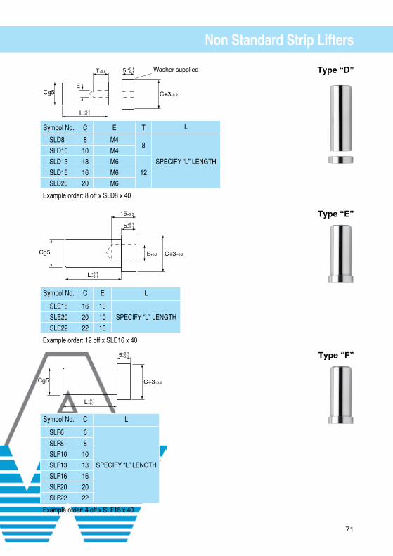
Non Standard Strip Lifters
Type “A”
Type “B”
Type “C”
Symbol No. C A0.5 INCREMENTS
D B L
SLXA6 6 2.0–3.0 3.6 7
SPECIFY “L” LENGTH
SLXA8 8 2.0–3.0 5.0 7SLXA10 10 2.0–3.0 6.0 7SLXA13 13 2.0–4.0 7.0 7SLXA16 16 2.0–6.0 8.0 12SLXA20 20 3.0–6.0 10.0 12
Example order: 10 off SLA8 x 2.0 x 40
Symbol No. C A0.5 INCREMENTS
D B E L
SLXB16 16 2.0–6.0 8.0 12 10SPECIFY “L” LENGTHSLXB20 20 3.0–6.0 10.0 12 12.5
SLXB22 22 3.0–6.0 12.0 12 16
Example order: 6 off SLB16 x 2.0 x 40
Symbol No. C A0.5 INCREMENTS
D B E T L
SLXC8 8 2.0–3.0 5.0 7 M48
SPECIFY “L” LENGTHSLXC10 10 2.0–3.0 6.0 7 M4SLXC13 13 2.0–4.0 7.0 7 M6
12SLXC16 16 2.0–6.0 8.0 12 M6SLXC20 20 3.0–6.0 10.0 12 M6
Example order: 8 off SLC8 x 2.0 x 40
5 +0.1−0.1
−0.2
+−
0.20
+0.5
+0.1
+0.2 -0.2
−0.1
+−
0.20
+−
0.20 T+0.5 5−0.1
−0.2
+0.1
71
Non Standard Strip Lifters
Type “D”
Type “E”
Type “F”
Symbol No. C E L
SLE16 16 10SPECIFY “L” LENGTHSLE20 20 10
SLE22 22 10
Example order: 12 off x SLE16 x 40
Symbol No. C L
SLF6 6
SPECIFY “L” LENGTH
SLF8 8SLF10 10SLF13 13SLF16 16SLF20 20SLF22 22
Example order: 4 off x SLF16 x 40
EC+3
Washer supplied
Cg5
L+0.1−0.1
5 +0.1−0.1
−0.2
T+0.5
5
15
C+3ECg5
L+0.1−0.1
+0.2 −0.2
+0.5
+0.1−0.1
5
C+3Cg5
L+0.1−0.1
+0.1−0.1
−0.2
Symbol No. C E T L
SLD8 8 M48
SPECIFY “L” LENGTHSLD10 10 M4SLD13 13 M6
12SLD16 16 M6SLD20 20 M6
Example order: 8 off x SLD8 x 40

72
Punch & Die Clearances
73
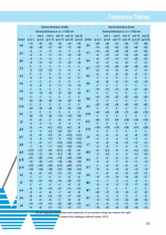
Tolerance TablesExternal dimensions (shafts) Internal dimensions (bores)
Nominal dimensions in .m = 1/1000 mm Nominal dimensions in .m = 1/1000 mm
Symbol1
up to 3over 3up to 6
over 6up to 10
over 10up to 18
over 18up to 30
over 30up to 50
Symbol
1up to 3
over 3up to 6
over 6up to 10
over 10up to 18
over 18up to 30
over 30up to 50
e 8–14 –20 –25 –32 –40 –50
E 8+28 +38 +47 +59 +73 +89
–28 –38 –47 –59 –73 –89 +14 +20 +25 +32 +40 +50
g 5–2 –4 –5 –6 –7 –9
F 7+16 +22 +28 +34 +41 +50
–6 –9 –11 –14 –16 –20 +6 +10 +13 +16 +20 +25
g 6–2 –4 –5 –6 –7 –9
G 6+8 +12 +14 +17 +20 +25
–8 –12 –14 –17 –20 –25 +2 +4 +5 +6 +7 +9
h 30 0 0 0 0 0
G 7+12 +16 +20 +24 +28 +34
–2 –2,5 –2,5 –3 –4 –4 +2 +4 +5 +6 +7 +9
h 50 0 0 0 0 0
H 5+4 +5 +6 +8 +9 +11
–4 –5 –6 –8 –9 –11 0 0 0 0 0 0
h 60 0 0 0 0 0
H 6+6 +8 +9 +11 +13 +16
–6 –8 –9 –11 –13 –16 0 0 0 0 0 0
h 80 0 0 0 0 0
H 7+10 +12 +15 +18 +21 +25
–14 –18 –22 –27 –33 –39 0 0 0 0 0 0
h 90 0 0 0 0 0
H 8+14 +18 +22 +27 +33 +39
–25 –30 –36 –43 –52 –62 0 0 0 0 0 0
h 100 0 0 0 0 0
H 9+25 +30 +36 +43 +52 +62
–40 –48 –58 –70 –84 –100 0 0 0 0 0 0
h110 0 0 0 0 0
H 10+40 +48 +58 +70 +84 +100
–60 –75 –90 –110 –130 –160 0 0 0 0 0 0
j 6+4 +6 +7 +8 +9 +11
H 11+60 +75 +90 +106 +130 +160
–2 –2 –2 –3 –4 –5 0 0 0 0 0 0
js 6+3 +4 +4,5 +5,5 +6,5 +8
H 12+100 +120 +150 +180 +210 +250
–3 –4 –4,5 –5,5 –6,5 –8 0 0 0 0 0 0
js 7+5 +6 +7,5 +9 +10,5 +12,5
J 6+2 +5 +5 +6 +8 +10
–5 –6 –7,5 –9 –10,5 –12,5 –4 –3 –4 –5 –5 –6
js 8+7 +9 +11 +13,5 +16,5 +19,5
J 7+4 +6 +8 +10 +12 +14
–7 –9 –11 –13,5 –16,5 –19,5 –6 –6 –7 –8 –9 –11
js 9+12,5 +15 +18 +21,5 +26 +31
JS 5+2 +2,5 +3 +4 +4,5 +5,5
–12,5 –15 –18 –21,5 –26 –31 –2 –2,5 –3 –4 –4,5 –5,5
js 13+70 +90 +110 +135 +165 +195
K 60 +2 +2 +2 +2 +3
–70 –90 –110 –135 –165 –195 –6 –6 –7 –9 –11 –13
js 14+125 +150 +180 +215 +260 +310
K 70 +3 +5 +6 +6 +7
–125 –150 –180 –215 –260 –310 –10 –9 –10 –12 –15 –18
k 6+6 +9 +10 +12 +15 +18
K 80 +5 +6 +8 +10 +12
0 +1 +1 +1 +2 +2 –14 –13 –16 –19 –23 –27
k7+10 +13 +16 +19 +23 +27
M 6–2 –1 –3 –4 –4 –4
0 +1 +1 +1 +2 +2 –8 –9 –12 –15 –17 –20
m 4+5 +8 +10 +12 +14 +16
M 7–2 0 0 0 0 0
+2 +4 +6 +7 +8 +9 –62 –12 –15 –18 –21 –25
m 5+6 +9 +12 +15 +17 +20
N 7–4 –4 –4 –5 –7 –8
+2 +4 +6 +7 +8 +9 –14 –16 –19 –23 –28 –33
n 6+10 +16 +19 +23 +28 +33
P 7–6 –8 –9 –11 –14 –17
+4 +8 +10 +12 +15 +17 –16 –20 –24 –29 –35 –42
As an ongoing development and expansion of our product range we reserve the right
to amend this catalogue without notice. 2012

74
Materials & CoatingsOur products are available in.
Unless specified AW Precision reserve the right to use either D2 or HSS / M2
A2 -1.2363 Tough, resistance to abrasion, an excellent steel for general punch & die applications
D2 -1.2379 A good quality tool steel for punching and forming
M2 -1.3343 For applications where high speed piercing, highly abrasive materials such as stainless and other special steels. Our preferred material choice.
PM A special high speed steel manufactured by a powder metallurgy method. A combination of high wear resistance and toughness make it a good choice for improved quality
Powder ToolSteel - ASP, CPM, Vanadis
Punch Heads Drawn 45hrc - 55hrcPlease specify your material choice
BENEFITS OF RECOMMENDED COATINGS• Longer service life & higher press stroke rates• Decreased down time to replace parts• Less lubricants, thus making them more environmentally friendly• Prevention of cold welding• Minimises friction thus requiring less stripping pressure
Example Order:
MT6B 5.5 x 70 HSS TINOther coatings available contact sales for advice.
Coating Material Microhardness* (HV 0.05)
Friction coefficient* against steel (dry)
Max. service temperature (°C) Coating colour
TiN (Balinit ® A) 2,300 0.4 600 gold-yellow
TiCN (Balinit ® B) 3,000 0.4 400 blue-grey
CrN (Balinit ® D) 1,750 0.5 700 silver-grey
TiAlN(Balinit ® Futura Nano) 3,300 0.30 - 0.35 900 violet-grey
DLC (a-C:H)(Balinit ® Triton) 2,500 0.5 350 black-grey
AlCrN(Balinit ® Alcrona Pro) 3,200 0.35 1100 light-grey

75
BSI Certificate ISO 9001:2008
QUALITY MANAGEMENT SYSTEM - ISO 9001:2008
This is to certify that:
A W Precision LtdCosford LaneSwift Valley Industrial EstateRugbyCV21 1QNUnited Kingdom
Holds Certificate No: Q 09086and operates a Quality Management System which complies with the requirements of ISO 9001:2008 for the followingscope:
The manufacture and supply of press tooling. Sub-contract machining services.The manufacture and supply of press tooling. Sub-contract machining services.
For and on behalf of BSI:
Chair, Certification Body Management Committee.
Originally registered: 01/12/1989 Latest Issue: 14/11/2011 Expiry Date: 10/12/2014
Page: 1 of 1
This certificate was issued electronically and remains the property of BSI and is bound by the conditions of contract.An electronic certificate can be authenticated online.Printed copies can be validated at www.bsigroup.com/ClientDirectory
The British Standards Institution is incorporated by Royal Charter.BSI (UK) Headquarters: Kitemark Court, Davy Avenue, Knowlhill, Milton Keynes MK5 8PP. Tel: 0845 080 9000

76
Thread Form Punch & DieMinimum
Form Diameter(Reference)
Materialthickness
Pitch
Minor diameter of screw(Pitch dia. of a type “C” screw)
Pitch
Approx1.25 x Pitch
plus materialthickness
Thread Size MaterialThickness Pitch (Ref.) Max. Minor
Dia. Of ScrewMinimumForm Dia,
TYPE “A” SCREWS
6 - 18 .020 - .030 .0556 .102 .276
8 - 15 .025 - .040 .0667 .123 .306
10 - 12 .030 - .045 .0833 .133 .352
12 - 11 .035 - .054 .0909 .162 .406
14 - 10 .038 - .060 .1000 .185 .442
20 - 9 .050 - .060 .1111 .234 .556
TYPE “B” AND “A” SCREWS
6 - 20 .020 - .030 .0500 .104 .208
8 - 18 .020 - .030 .0556 .122 .296
10 - 16 .020 - .030 .0625 .141 .374
12 - 14 .030 - .040 .0714 .164 .400
1/4 - 14 .030 - .040 .0714 .192 .400
5/16 - 12 .030 - .040 .0833 .244 .552
TYPE “C” SCREWS (MACHINE SCREWS)
6 - 32 .010 - .020 .0313 .118 .290
8 - 32 .010 - .020 .0313 .144 .324
10 - 24 .015 - .025 .0417 .163 .370
10 - 32 .010 - .020 .0313 .170 .348
1/4 - 20 .020 - .030 .0500 .218 .478
5/16 - 18 .020 - .030 .0556 .276 .490
Metric Conversion
All screw sizes are shown in inch diemensions. Most metric sheet metal screws, however, are standard inch sizes converted into millimeter dimensions. If screws cannot be found in metric sizes, the equivalent inch sizes can be used.

77
Thread Form Punch & Die
60ºQ Ref
2.5”
P
D
P +.001-.000
0.310.25
1/32 X 45º R .010+-
1.1911.187
D
P +.001-.000
0.310.25
1/32 X 45º R .010+-
0.9420.937
Re�ected View Re�ected View
Re�ected View Re�ected View
PiercePunch Hole
+.0005-.0000
2.1582.154
D
Countersink
1/32 x 45º
0.310.25
PiercePunchRelief
PiercePunch Hole
+.0005-.0000
2.1662.156
D
Countersink
0.310.25
PiercePunchRelief
H +.000-.010
T +.010-.000

Cosford Lane, Rugby. CV21 1QN, UKTel: +44 (0)1788 542271, Fax: +44 (0)1788 561256
Email: [email protected], Web: www.awprecision.com
pro
duc
ed b
y w
ww
.dru
kujc
ie.c
om.p
l
Certificate No. Q 09086