metric mil-std-2105d superseding 14 july 2003...
TRANSCRIPT
METRIC
MIL-STD-2105D 19 April 2011 SUPERSEDING MIL-STD-2105C 14 July 2003
DEPARTMENT OF DEFENSE
TEST METHOD STANDARD
HAZARD ASSESSMENT TESTS FOR NON-NUCLEAR MUNITIONS AMSC 9200 AREA SAFT DISTRIBUTION STATEMENT A: Approved for public release; distribution is unlimited.
Downloaded from http://www.everyspec.com

MIL-STD-2105D
ii
FOREWORD 1. This military standard is approved for use by all Departments and Agencies of the Department of Defense. 2. Comments, suggestions, or questions on this document should be addressed to DEPARTMENT OF THE NAVY, Indian Head Division, NSWC, Code E12AP, Document Control, 4123 Artisans Court, Suite 103, Indian Head, MD 20640-5115 OFFICIAL BUSINESS, or emailed to [email protected]. Since contact information can change, you may want to verify the currency of this information using the ASSIST Online database at https://assist.daps.dla.mil. 3. This document contains a description of tests or references to NATO Standardization Agreements (STANAGs) for the assessment of munition safety and Insensitive Munitions (IM) characteristics of non-nuclear munitions. Historically, this standard was used primarily for the assessment of weapon safety. The standard was later revised to add additional IM tests as called out by the Joint Service Requirement for Insensitive Munitions (JSRIM), and now by various NATO STANAGs. The previous revision made a distinction between weapon safety tests and the IM tests, even though these tests may often be contained in the same system hazard assessment test program. This revision updates the applicable documents in section 2, and provides updates to the IM tests (section 5.2) based on the Joint Requirements Oversight Council (JROC) recommendation of a standardized, single set of IM tests and passing criteria for use by all Components for assessing IM compliance, as directed by the Under Secretary of Defense for Acquisition, Technology and Logistics memorandum of February 1, 2010. 4. Three sets of tests are commonly used to assess munitions with respect to hazards: IM tests as contained or contained in this standard; Hazard Classification (HC) tests used to classify munitions for transportation and storage purposes; and basic safety tests used to assess munition safety and suitability response or system vulnerability. In order to best utilize limited resources and avoid test redundancy, tailor IM test plans to the maximum extent possible, so that all three sets of tests can be addressed in one coordinated test program with the minimum number of samples. It is recommended that test plans be coordinated with the appropriate service hazard classifier and the Department of Defense Explosives Safety Board (DDESB), 2461 Eisenhower Avenue, Alexandria, VA 22331-0600, when a DOD hazard classification for an item is to be obtained in accordance with TB 700-21.
1 TB 700-2, "Department of Defense Ammunition and Explosives Hazard Classification Procedures," is
Downloaded from http://www.everyspec.com
MIL-STD-2105D
iii
5. Additional or modified hazard testing may be required to fully assess the tactical and logistical vulnerability of the given weapon system against the probable threats to which the system may be subjected. Accordingly, project managers and munition developers will conduct a threat hazard assessment to determine the adequacy of Safety or IM tests as referenced or specified in this standard. If the assessment indicates that different environmental hazards or threats to the weapon system pose additional vulnerability problems, tailor the tests to meet those requirements and provide rationale to support the assessment. 6. Program managers are responsible for planning and executing a hazard assessment test program. The hazard assessment test program includes a test plan based on a realistic life cycle environmental profile. Program managers should establish safety design goals for the test plan and have these goals approved by the service review organization within the applicable department. Program managers should generate a test report for submission to their service review organization. 7. The service review organization should review the test plan and test report and examine the results of the hazard assessment test program to ensure that safety and IM requirements are met. The service review organization should produce a final recommendation for or against service use of the weapon system. For joint programs, all affected service review organizations should conduct this review and examination and develop a final recommendation.
also known as NAVSEAINST 8020.8, TO 11A-1-47, and DLAR 8220.1.
Downloaded from http://www.everyspec.com

MIL-STD-2105D
iv
CONTENTS PARAGRAPH PAGE 1. SCOPE............................................... 1 1.1 Scope............................................... 1 1.2 Purpose............................................. 1 1.3 Application......................................... 1 2. APPLICABLE DOCUMENTS................................ 2 3. DEFINITIONS......................................... 6 4. GENERAL REQUIREMENTS................................ 9 4.1 General............................................. 9 4.1.1 Test plan........................................... 9 4.1.2 Environmental profile............................... 9 4.1.3 Threat hazard assessment (THA)...................... 9 4.2 Test parameters..................................... 9 4.2.1 Test item temperature............................... 9 4.3 Passing criteria.................................... 10 4.4 Hazard assessment test report...................... 10 4.5 Hardware........................................... 10 4.6 Test facilities.................................... 11 4.6.1 Witness plates..................................... 11 4.7 Configuration...................................... 11 4.8 Pre-test examination............................... 11 4.9 Post-test requirements............................. 12 4.10 Photographic requirements.......................... 12 5. DETAILED REQUIREMENTS.............................. 13 5.1 Basic safety tests................................. 13 5.1.1 28-day temperature and humidity (T&H) test......... 13 5.1.2 Vibration test..................................... 14 5.1.3 4-day temperature and humidity (T&H) test.......... 15 5.1.4 12-meter (40-foot) drop test....................... 16 5.2 Insensitive Munitions (IM) tests................... 16 5.2.1 Fast cook-off test................................. 16 5.2.2 Slow cook-off test................................. 17 5.2.3 Bullet impact test................................. 17 5.2.4 Fragment impact test............................... 19 5.2.5 Sympathetic detonation test........................ 19 5.2.6 Shaped charge jet impact test...................... 19 5.2.7 Spall impact test.................................. 19 5.3 Additional tests................................... 22
Downloaded from http://www.everyspec.com

MIL-STD-2105D
v
6. NOTES.............................................. 24 6.1 Intended use....................................... 24 6.2 Issue of DODISS.................................... 24 6.3 Data requirements.................................. 24 6.4 Tailoring guidance................................. 25 6.5 Submission of test reports and results............. 25 6.6 Service review organizations....................... 25 6.7 Tests for hazard classification.................... 26 6.8 Units of measurement and abbreviations............. 27 6.9 Subject term (key word) listing.................... 27 6.10 International standardization agreements........... 27 6.11 Changes from previous issue........................ 28 FIGURE 1. Relationship of Projection Kinetic Energy and Hazard Division (20 J).................................... 10 2. "Typical" item number and test sequence............ 12 3. "Typical" spall impact test configuration.......... 21
Downloaded from http://www.everyspec.com

MIL-STD-2105D
1
1. SCOPE 1.1 Scope. This standard provides or references tests and test procedures for the assessment of safety and Insensitive Munitions (IM) characteristics for all non-nuclear munitions, munition subsystems, and explosive devices. 1.2 Purpose. The purpose is to provide a framework for the development of a consolidated safety and IM assessment test program for non-nuclear munitions. The tests are to characterize the munitions and provide the service review organization information with which to make a decision. 1.3 Application. This standard applies to all non-nuclear munitions (i.e., all-up missiles, rockets, pyrotechnics) and munitions subsystems (e.g., warheads, fuzes, cartridge actuated devices, propulsion units, safe and arm devices, pyrotechnic devices, chemical payloads) and other explosive devices. In all likelihood, it may not be possible to test against all threats. In this case, select the most probable, credible stimuli that are expected to cause the greatest damage to life, property, or combat effectiveness. 2. APPLICABLE DOCUMENTS 2.1 General. The documents listed in this section are specified in sections 3, 4, or 5 of this standard. This section does not include documents cited in other sections of this standard or recommended for additional information or as examples. While every effort has been made to ensure the completeness of this list, document users are cautioned that they must meet all specified requirements documents specified in sections 3, 4 or 5 of this standard, whether or not they are listed. 2.2 Government documents. 2.2.1 Specifications, standards, and handbooks. The following specifications, standards, and handbooks form a part of this document to the extent specified herein. Unless otherwise specified, the issues of these documents are those cited in the solicitation or contract.
Downloaded from http://www.everyspec.com

MIL-STD-2105D
2
DEPARTMENT OF DEFENSE STANDARDS MIL-STD-167/1 Mechanical Vibrations of Shipboard Equipment (Type I – Environmental and Type II – Internally Excited) MIL-STD-167/2 Mechanical Vibrations of Shipboard Equipment (Reciprocating Machinery and Propulsion System and Shafting) Types III, IV, and V MIL-STD-331 Fuze and Fuze Components, Environmental and Performance Tests MIL-STD-810 Environmental Engineering Considerations and Laboratory Tests MIL-STD-882 Standard Practice for System Safety DEPARTMENT OF DEFENSE HANDBOOKS MIL-HDBK-310 Global Climatic Data for Developing Military Products MIL-HDBK-1670 Environmental Criteria and Guidelines for Air-Launched Weapons (Unless otherwise indicated, copies of federal and military specifications, standards, and handbooks are available from ASSIST Online at https://assist.daps.dla.mil.) 2.3 Non-Government publications. The following documents form a part of this document to the extent specified herein. Unless otherwise specified, the issues of these documents are those cited in the solicitation or contract. NORTH ATLANTIC TREATY ORGANIZATION AECTP-100 Allied Environmental Conditions and Test
Publication (AECTP) 100, Environmental Guidelines for Defence Materiel (under STANAG 4370)
AECTP-200 Allied Environmental Conditions and Test
Publication (AECTP) 200, Environmental Conditions (under STANAG 4370)
Downloaded from http://www.everyspec.com

MIL-STD-2105D
3
AECTP-300 Allied Environmental Conditions and Test
Publication (AECTP) 300, Climatic Environmental Tests (under STANAG 4370)
AECTP-400 Allied Environmental Conditions and Test
Publication (AECTP) 400, Mechanical Environmental Tests (under STANAG 4370)
STANAG 4240 Liquid Fuel/External Fire, Munition Test
Procedures STANAG 4241 Bullet Impact, Munition Test Procedures STANAG 4370 Environmental Testing STANAG 4375 Safety Drop, Munition Test Procedure STANAG 4382 Slow Heating, Munitions Test Procedures STANAG 4396 Sympathetic Reaction, Munition Test
Procedures STANAG 4439 Policy for Introduction and Assessment of
Insensitive Munitions (IM) STANAG 4496 Fragment Impact, Munitions Test Procedure STANAG 4526 Shaped Charge Jet, Munitions Test
Procedure AOP-38 Specialist Glossary of Terms and
Definitions on Ammunition Safety AOP-39 Guidance on the Assessment and Development
of Insensitive Munitions (IM) (Application for copies should be addressed to NATO/MAS, BvdLeopold 111, 1110 Brussels, BE. NATO documents may also be obtained from ASSIST Online at http://assist.daps.dla.mil.) UNITED NATIONS (UN) UN Orange Book Fifteenth Recommendations on the Transport
of Dangerous Goods, Tests and Criteria, United Nations, New York
(Application for copies should be addressed to United Nations Publications Customer Service, c/o National Book Network,
Downloaded from http://www.everyspec.com

MIL-STD-2105D
4
15200 NBN Way, PO Box 190, Blue Ridge Summit, PA 17214 USA at https://unp.un.org/.) AMERICAN NATIONAL STANDARDS INSTITUTE (ANSI) ASME Y14.3M-2003 Multiview and Sectional View Drawings (Application for copies should be addressed to the American National Standards Institute, 25 West 43rd Street, New York, NY 10036 at www.ansi.org.)
AMERICAN SOCIETY FOR TESTING AND MATERIALS (ASTM) ASTM E1742/E1742M /E1742/E1742M M ........................ Standard Practice for Radiographic Examination (Application for copies of ASTM standards should be sent to the ASTM International, 100 Barr Harbor Drive, PO Box C700, West Conshohocken, PA 19428-2959 at http://www.astm.org.) 2.4 Order of precedence. Unless otherwise noted herein or in the contract, in the event of a conflict between the text of this document and the references cited herein, the text of this document takes precedence. Nothing in this document, however, supersedes applicable laws and regulations unless a specific exemption has been obtained. 3. DEFINITIONS 3.1 All-up-round (AUR). This refers to the completely assembled munition as intended for delivery to a target or configured to accomplish its intended mission. This term is identical to the term all-up-weapon. 3.2 Bare round or configuration. A munition with no external protection or shielding from the environment such as a container, barrier, or shield. 3.3 Explosive. An explosive is a solid or liquid energetic substance (or a mixture of substances) which is in itself capable, by chemical reaction, of producing gas at such temperature, pressure, and speed as to cause damage to the surroundings. Included are pyrotechnic substances even when they do not evolve gases. The term explosive includes all
Downloaded from http://www.everyspec.com

MIL-STD-2105D
5
solid and liquid energetic materials variously known as high explosives and propellants together with igniter, primer, initiation, and pyrotechnic (e.g., illuminant, smoke, delay, decoy, flare, and incendiary) compositions. 3.4 Explosive device. An item that contains explosive material(s) and is configured to provide quantities of gas, heat, or light by a rapid chemical reaction initiated by an energy source usually electrical or mechanical in nature. 3.5 Exudation. A discharge or seepage of material. The material may be a component of a chemical payload, a component of an explosive/propellant payload, or a reaction product from incompatibility or aging of munition components. 3.6 Hazardous fragment. For personnel, a hazardous fragment is a piece of the reacting weapon, weapons system, or container having an impact energy of 79 Nm (58 lbfft) (see paragraph 6.7) or greater. 3.7 Insensitive munitions (IM). Munitions which reliably fulfill (specified) performance, readiness, and operational requirements on demand but which minimize the probability of inadvertent initiation and severity of subsequent collateral damage to the weapon platforms, logistic systems, and personnel when subjected to unplanned stimuli. 3.8 Munition. An assembled ordnance item that contains explosive material(s) and is configured to accomplish its intended mission. 3.9 Munition subsystem. An element of an explosive system that contains explosive material(s) and that, in itself, may constitute a system. 3.10 Propulsion. A reaction whereby adequate force is produced to impart flight to the test item in its least restrained configuration as determined by the life cycle analysis. 3.11 Response descriptors.
a. Type I (Detonation reaction). The most violent type of munition reaction where the energetic material is consumed in a supersonic decomposition.
Downloaded from http://www.everyspec.com
MIL-STD-2105D
6
Primary evidence of a Type I reaction is the observation or measurement of a shock wave with the magnitude and timescale of a purposely detonated calibration test or calculated value, and the rapid plastic deformation of the metal casing contacting the energetic material with extensive high shear rate fragmentation. Secondary evidence may include the perforation, fragmentation and/or plastic deformation of a witness plate and ground craters of a size corresponding to the amount of energetic material in the munition. b. Type II (Partial detonation reaction). The second most violent type of munition reaction where some of the energetic material is consumed in a supersonic decomposition. Primary evidence of a Type II reaction is the observation or measurement of a shock wave with magnitude less than that of a purposely detonated calibration test or calculated value and the rapid plastic deformation of some, but not all, of the metal casing contacting the energetic material with extensive high shear rate fragmentation. Secondary evidence may include scattered burned or unburned energetic material; the perforation, fragmentation, and/or plastic deformation of a witness plate; and ground craters. c. Type III (Explosion reaction). The third most violent type of munition reaction with sub-sonic decomposition of energetic material and extensive fragmentation. Primary evidence of a Type III reaction is the rapid combustion of some or all of the energetic material once the munition reaction starts and the extensive fracture of metal casings with no evidence of high shear deformation resulting in larger and fewer fragments than observed from purposely detonated calibration tests. Secondary evidence may include significant long-distance scattering of burning or unburned energetic material; witness plate damage; the observation or measurement of overpressure throughout the test arena with a peak magnitude significantly less than and significantly longer duration than that of a purposely detonated calibration test; and ground craters.
Downloaded from http://www.everyspec.com

MIL-STD-2105D
7
d. Type IV (Deflagration reaction). The fourth most violent type of munition reaction with ignition and burning of confined energetic materials which leads to a less violent pressure release. Primary evidence of a Type IV reaction is the combustion of some or all of the energetic material and the rupture of casings resulting in a few large pieces that might include enclosures and attachments. At least one piece (e.g., casing, packaging, or energetic material) travels (or would have been capable of travelling) beyond 15m and with an energy level greater than 20J based on the distance versus mass relationships in figure 1. A reaction is also classified as Type IV if there is no primary evidence of a more severe reaction and there is evidence of thrust capable of propelling the munition beyond 15m. Secondary evidence may include a longer reaction time than would be expected in a Type III reaction; significant scattered burning or unburned energetic material, generally beyond 15m; and some evidence of pressure in the test arena which may vary in time or space.
e. Type V (Burning reaction). The fifth most violent type of munition reaction where the energetic material ignites and burns nonpropulsively.
Primary evidence of a Type V reaction is the low pressure burn of some or all of the energetic material. The casing may rupture resulting in a few large pieces that might include enclosures and attachments. No piece (e.g., casing, packaging, or energetic material) travels (or would have been capable of travelling) beyond 15m and with an energy level greater than 20J based on the distance versus mass relationships in figure 1. There is no evidence of thrust capable of
propelling the munition beyond 15m. A small amount of burning or unburned energetic material relative to the total amount in the munition may be scattered, generally within 15m but no more than 30m.
Secondary evidence may include some evidence of insignificant pressure in the test arena and for a rocket motor a significantly longer reaction time than if initiated in its design mode.
Downloaded from http://www.everyspec.com

MIL-STD-2105D
8
FIGURE 1. Relationship of projection kinetic energy and hazard division (20 J).
f. Type VI (No reaction). The least violent type of munition response where any reaction is self-extinguished immediately upon removal of the external stimulus. Primary evidence of a Type VI reaction is no reaction of the energetic material without a continued external stimulus; the recovery of all or most of the energetic material with no indication of sustained combustion; and no fragmentation of the casing or packaging greater than from a comparable inert test item.
Secondary evidence – none.
3.12 Service review organization. The various organizations within the services which are responsible for the assessment of weapon safety or IM characteristics (see paragraph 6.6). Note: Referred in NATO STANAGs as National S3 Authority.
0
10
20
30
40
50
60
70
80
90
0 100 200 300 400 500 600
Equation for 20 Joules:D = 4.212 * m (‐1.103 ‐ 0.0788 * ln (m))
Ref: TB 700‐2 2005 Draft
Type V
Relationship of Projection Kinetic Energy and IM Response Descriptor
Type V
Type I‐IV
Mass (g)
Distance (m
)
Note 1: This chart is intended to aid in the determination of the IM reaction for munitions that produce projections. It is not intended for bare explosive charges (i.e. demolition charges) since they may detonate or explode without producing fragments with energy greater than 20J. The measurement of overpressure should always be taken into account along with other test instrumentation data to determine the proper reaction type.
Mass (g)
Projection distance (m)
25 84.31
50 56.55
75 43.22
100 35.16
125 29.69
150 25.71
175 22.67
200 20.27
277 15
300 14.18
400 10.83
500 8.71
600 7.25
Type V/VI at (0,0)
Downloaded from http://www.everyspec.com

MIL-STD-2105D
9
3.13 Sympathetic reaction. The reaction of a munition or an explosive charge induced by the detonation of another like munition or explosive charge. 3.14 Threat hazard assessment (THA). An evaluation of the munition life cycle environmental profile to determine the threats and hazards to which the munition may be exposed. The assessment includes threats posed by friendly munitions, enemy munitions, accidents, handling, environmental lifecycle conditions, etc. Base the assessment on analytical or empirical data to the extent possible. The THA should also contain the potential reaction of the munition to the threats identified as well as the likely resulting collateral damage. The THA should be updated as the exposure environment changes. A source of information to guide the development of the THA may be found in AOP-39. Paragraphs 5.2, 5.3, and table 1 of AOP-39 aid in identifying the threats to a munition as well as the configurations seen throughout the munitions lifecycle. A THA should also be properly coordinated with the Operational User, Logistician, service review organization, Program Manager, Design Authority of each participating service. The THA should take into account the worst case scenarios that the item will see in each of its intended environments. 3.15 Weapon system. A munition and those components and equipment required for its operation and support. 4. GENERAL REQUIREMENTS 4.1 General. A hazard assessment test program includes a test plan generated in concert with an environmental profile and a THA. Provide rationale for not including or modifying any hazards or tests contained or referenced in this document to the service review organization for review and approval prior to executing the test program. 4.1.1 Test plan. Develop a test plan, and base it on the life cycle environmental profile. Include in the test plan provisions for the conduct and sequence of tests, and any environmental conditioning as illustrated on figure 2. A review and concurrence is required by the appropriate service review organization(s) prior to conduct of the tests, and the review organization(s) may authorize variations to the tests and procedures in this document when justified. The test plan may
Downloaded from http://www.everyspec.com

MIL-STD-2105D
10
include additional tests selected from other sources or devised to investigate hazardous conditions and environments identified by hazard analyses performed as part of the system safety program described in MIL-STD-882.
FIGURE 2. “Typical” item number and test sequence.
4.1.2 Test variation. Any variations to the Standardized IM tests must be first coordinated with the applicable Service/Agency IM/HC authorities who will then process the request as appropriate for Joint approval.
Visual Inspection
Radiographic Inspection
Visual Inspection
Radiographic Inspection
Visual Inspection
Radiographic Inspection
Visual Inspection
Radiographic Inspection
Visual Inspection
Radiographic Inspection
Visual Inspection
Radiographic Inspection
Visual Inspection
Radiographic Inspection
Visual Inspection
Radiographic Inspection
Visual Inspection
Radiographic Inspection
Visual Inspection
Radiographic Inspection
28-day Temperature and Humidity Test
(see 5.1.1)
Fast Cook-off Test(see 5.2.1)
Slow Cook-off Test(see 5.2.2)
Bullet Impact Test(see 5.2.3)
Fragment Impact Test(see 5.2.4)
Sympathetic Reaction Test
(see 5.2.5)
Shaped Charge Jet Impact Test(see 5.2.6)
Vibration Test (see 5.1.2)
4-day Temperature and Humidity Test
(see 5.1.3)
12-meter Drop Test(see 5.1.4)
Forward end down
HorizontalAft end down
Item 1 2 3 4 5 6 7 8 9 10 11 12-16 17 18
Tes
t S
equ
ence
IM TestsBasic Safety
Tests
Downloaded from http://www.everyspec.com

MIL-STD-2105D
11
4.1.3 Threat hazard assessment (THA). Develop a THA (see paragraph 6.2) and ensure it contains an analysis of the munition life cycle. In the THA, identify potential hazards both qualitatively and quantitatively and their causes and effects. Submit the THA to the appropriate service review organization(s) for approval. A review and concurrence of the THA is required by the appropriate service review organization(s) prior to conduct of the tests. 4.1.3.1 Environmental profile. As part of the THA, develop a life cycle environmental profile (LCEP) using the guidance available in other documents for establishing such profiles, (e.g., MIL-HDBK-1670 for air launched weapons or MIL-STD-810 for general applications). Included in the LCEP are the worst case environmental conditions and limits that munitions will encounter throughout the life cycle such as temperature, humidity, and vibration. MIL-HDBK-310 contains information to assist in developing the climatic portion of an environmental profile. Use the environmental profile in performing the THA, and cite it in the test plan. 4.2 Test parameters. Determine the safety and sensitivity characteristics of the item under conditions that simulate or duplicate the hazards of credible normal, abnormal, or combat situation(s) identified by the THA (see paragraph 6.2). Select the test parameters to reflect maximum stress levels forecasted by the THA (e.g., bullet impact velocity, maximum storage temperature). 4.2.1 Test item temperature. Unless otherwise specified (see paragraph 6.3), ensure all ambient temperature test items are at 25 ± 10 degrees Celsius (C) (77 ± 18 degrees Fahrenheit (F)). 4.3 Passing criteria. Passing criteria for the tests are in section. Failure to meet all predetermined test criteria is not necessarily grounds for automatic rejection of that weapon system for service use.
4.4 Hazard assessment test report. Develop a hazard assessment test report (see paragraph 6.2) that contains detailed information specified herein (see section 5) and is consistent with the test plan (see paragraph 4.1.1). Include in
Downloaded from http://www.everyspec.com

MIL-STD-2105D
12
the report; rationale for deviations from the test plan (with an analysis showing why the results should be accepted), test item configuration and identification, test date, test results, and safety and vulnerability related conclusions that may be drawn from the test results. 4.5 Hardware. Ensure the item to be tested is either production hardware or a representative of production hardware. Use of simulated components for non-explosive components is acceptable providing they accurately simulate the thermal, confinement, mass, and retention characteristics of their counterparts. When the item differs from production hardware, describe the configuration in the test plan. 4.6 Test facilities. Ensure the test chamber or test fixtures used do not interfere with the test stimulus being imposed on the test item or influence the subsequent reaction of the item. Unless otherwise specified, use tolerances of test conditions and instrumentation calibrations in accordance with MIL-STD-810. 4.6.1 Witness plates. Witness plates are used to "witness" a reaction by providing an impact surface for fragments and shock waves. Design witness plates to survive a reaction and provide post-test physical evidence of its severity. Information regarding the degree of test item fragmentation may be obtained by locating witness plate(s) away from the test item. Use relatively thin plates to permit sufficient data collection of impacting fragments. Alternatively, information regarding the shock pressure produced by the reacting explosive(s) may be obtained by placing witness plate(s) in direct contact with the test item. Use plates of sufficient thickness, hardness, and strength to withstand detonation of the test item without fracturing. Determination of the specific number, types, sizes, and location of the witness plates is the responsibility of the testing activity. However, the testing activity must ensure the witness plates are integrated into the test setups in a manner that will not influence the response of the test item, and does
Downloaded from http://www.everyspec.com

MIL-STD-2105D
13
not compromise the collection of other required data while performing their function. Witness plate use and configuration should be included in detailed test plans submitted to the appropriate service IM review organizations for approval. 4.7 Configuration. Ensure the test item configuration accurately represents the configuration of the item in the life cycle phase being duplicated by the test. For fast cook-off, slow cook-off, bullet impact, sympathetic reaction, shaped charge jet, and 12 meter (40 ft) drop testing; refer to the respective STANAGs for test item configuration. Temperature and humidity tests may be done on the major munition subsystem level. The electronic or other sections not containing explosives may be mechanically, geometrically, and thermally simulated for any test. Specify the test item configuration to be used in detail in the test plan and have it approved by the service review organization. Mount the test items so they do not affect the munition response to the given test. 4.7.1 Logistical configuration (storage, shipping, or transportation). The logistical configuration is the packaged configuration in which the munition is stored, shipped, or transported. The tested configuration will include the appropriate palletization and strapping materials in accordance with the appropriate service’s applicable logistics documentation and drawings. In the event that a munition has different storage, shipping, or transportation configurations or multiple configurations, the configuration expected to result in the reaction to the test stimuli providing the maximum credible event will be tested. 4.7.2 Operational configuration. The operational configuration is the tactical configuration in which a munition is ready to be employed as an AUR in an unpackaged or bare state. In the case where a munition is not removed from its packaging or shipping container prior to employment, the logistical configuration testing should be replicated where the configuration requirements of section 5 specify any operational configuration tests. 4.8 Pre-test examination. Unless otherwise specified (see paragraph 6.3), prior to each test (see figure 2), conduct a visual and radiographic inspection of the test item, in accordance with ASTM E1742/E1742M , to ensure no unusual conditions exist that might invalidate the tests. Set or adjust
Downloaded from http://www.everyspec.com
MIL-STD-2105D
14
all unit safety mechanisms and devices to a safe condition. Take photographs of the test setup (see paragraph 6.2), and include identification information (such as nomenclature, MK, Mod, serial number, test facility, date, etc.) in the field of view. 4.9 Post-test requirements. Provide a complete description of all post-test remains of the munition. Document the location (distance from original test position), dimensions, and weight of each recovered part on the appropriate test data sheet. The appropriate service review organization determines the official reaction violence level. Provide data sheets with the test report and photograph the test remains (see paragraph 6.2). In the field of view include identification information (nomenclature, MK, Mod, test facility, date, etc.). 4.10 Photographic requirements. Select the photographic media to be used from the following (see paragraph 6.2). 4.10.1 Still photograph coverage. Take black and white or color still photographs or digital stills (with a minimum image resolution of one megapixel) as specified in the test plan, and use the film format size and the number of original prints and negatives as specified in the contract. When negative color material is used, include the original color negative and one matching positive color transparency. Place all negatives in negative preservers. 4.10.2 Video coverage. Use a digital video camera for video coverage. Do not edit the video footage. For normal speed video coverage, use a frame rate of 18 to 30 frames per second and include synchronous sound recording. For high speed video coverage, use a minimum frame rate of 400 frames per second or as required by the test plan (see paragraph 4.1.1). The sympathetic reaction test shall be recorded using high speed video cameras capable of photographing 32,000 images per second, minimum, or as required by the test plan (see paragraph 4.1.1). For video coverage, ensure that the means chosen (quality, speed, type) will adequately capture the reaction event so that a detailed analysis can be conducted. 4.10.3 Instrumentation photography. For instrumentation photography, produce color images with a time base recorded on the image but preferably in an area other than the image area.
Downloaded from http://www.everyspec.com
MIL-STD-2105D
15
5. DETAILED REQUIREMENTS 5.1 Basic safety tests. Consider all of the following tests for inclusion in the hazard assessment test program. Unless otherwise specified (see paragraph 6.3), test three test items sequentially as shown in figure 2. 5.1.1 28-day temperature and humidity (T&H) test. 5.1.1.1 Description of test. The 28-day T&H test consists of exposing the test item to alternating 24-hour periods (no period lasting less than 24 hours) of high and low temperatures for a total of 28 days. Derive the temperature range and relative humidity from the environmental profile of paragraph 4.1.3. Test a minimum of three test items. 5.1.1.2 Test procedure. Develop test procedures (see paragraph 6.2) that reflect the temperature and humidity conditions measured or forecast. Visually examine each test item prior to testing, and record the appropriate critical dimensions. Unless otherwise specified (see paragraph 6.3), prior to testing, radiographically examine the test items to determine material condition. 5.1.1.2.1 Test facilities. Use chambers that are capable of producing the required temperatures and humidity over the time spans specified in paragraph 5.1.1.1, and that do not obstruct the free flow of air in contact with the item under test. Recommend using separate chambers for each test environment specified. 5.1.1.2.2 Temperature cycling. Begin the test by subjecting the test item to either the high or low temperature environment for a 24-hour period. At the end of this period, transfer the test item to the other environment. Perform the transfer in less than 30 minutes, but if the transfer time exceeds 30 minutes, document the actual time in the test data report (see paragraphs 5.1.1.5 and 6.2). At the end of each high and low temperature cycle change, inspect the test item for damage and collect any exudate for chemical analysis. Continue testing and inspecting for the number of periods specified for the test.
Downloaded from http://www.everyspec.com

MIL-STD-2105D
16
5.1.1.2.3 Test interruptions. Minimize interruptions of the test. If the test is interrupted by slack labor periods (weekends, holidays), maintain the last test environment encountered prior to the slack period. Extend the test period as necessary to complete at least 20 temperature changes (hot/cold) or 10 full cycles. A full cycle consists of two temperature changes (e.g., hot-to-cold-to-hot). 5.1.1.3 Instrumentation. Continuously monitor and record the temperature and humidity levels of the test chamber. 5.1.1.3.1 Photography. Use still photographs to record the condition of the test item and test setup prior to and after the test (see paragraph 6.2). 5.1.1.3.2 Radiographic Inspection. Conduct a radiographic inspection in accordance with ASTM E-1742 to record the condition of the test item prior to and after the test. 5.1.1.4 Passing criteria. These criteria are based on the final observation. a. No reaction of the explosive. b. No exudation containing explosive material. c. Explosives do not crack or separate in a manner which would create a hazardous condition. d. All safety devices remain in the safe position or safe condition. e. The structural integrity of the item is not compromised by corrosion, loosening of joints, or other physical distortions. 5.1.1.5 Documentation. Develop a data sheet documenting the test results (see paragraph 6.2). 5.1.2 Vibration test. 5.1.2.1 Description of test. The vibration test consists of exposing the test item to the most intense vibration environment that it will encounter during the life cycle as
Downloaded from http://www.everyspec.com

MIL-STD-2105D
17
determined by the THA. Test a minimum of three items which have undergone testing in accordance with paragraph 5.1.1. 5.1.2.1.1 Vibration orientation. Conduct vibration tests along the appropriate mutually perpendicular axes. 5.1.2.1.2 Vibration schedule. Determine the vibration schedule from the environmental profile of paragraph 4.1.3. 5.1.2.1.3 Changes in vibration schedule. Changes in the selected schedule of vibration levels, frequency ranges, and time duration of the test can be affected by the program manager or the procuring activity with the approval of the service review organization. 5.1.2.1.4 Test temperatures. Conduct vibration tests at low and elevated temperatures or ambient temperature if the anticipated life cycle environment so dictates. 5.1.2.2 Test procedures. Develop test procedures (see paragraph 6.2) that reflect vibration modes and temperatures anticipated in the item's environment. Consider vibration environments as specified in MIL-STD-167 and MIL-STD-810 including one or more of the following. 5.1.2.2.1 Transportation vibration. If the item is always containerized when transported, vibrate the item in the container. Vibrate the item in the normal configuration as shipped. The item may be vibrated in the bare configuration if it can be shown that testing in the bare configuration produces an equivalent environment. If the item is stowed in a ready service configuration, vibrate the item in a fixture and orientation representative of that configuration. 5.1.2.2.2 Aircraft vibration. Vibrate the item in the configuration utilized for aircraft combat carriage. 5.1.2.2.3 Shipboard vibration. Vibrate the item in its shipboard stowage configuration. Should the item be carried on a launcher or in a ready service configuration, vibrate the item in a fixture and orientation representative of that configuration also.
Downloaded from http://www.everyspec.com

MIL-STD-2105D
18
5.1.2.3 Instrumentation. Record the test equipment inputs and test item responses. Record test item temperatures at both the skin and internal free space. 5.1.2.3.1 Photography. Use still photographs to record the condition of the test item and setup prior to and after the test (see paragraph 6.2). 5.1.2.3.2 Radiographic inspection. Conduct a radiographic inspection in accordance with ASTM E-1742 to record the condition of the test item prior to and after the test. 5.1.2.4 Passing criteria. These criteria are based on the final observation. a. No reaction of the explosive. b. No exudation containing explosive material. c. Explosives do not crack or separate in a manner which would create a hazardous condition. d. All safety devices remain in the safe condition. e. The structural integrity of the item is not compromised by corrosion, loosening of joints, or other physical distortions. 5.1.2.5 Documentation. Develop a data sheet documenting the test results (see paragraph 6.2). 5.1.3 4-day temperature and humidity (T&H) test. 5.1.3.1 Description of test. The 4-day T&H test is a 4-day version of the 28-day T&H test, and consists of exposing the item to alternating 24-hour periods of temperature and relative humidity as derived from the environmental profile of paragraph 4.1.3. All data relative to the 28-day T&H test is required for the 4-day T&H test (see paragraphs 5.1.1 and 6.2). Test a minimum of three items which have undergone testing in accordance with paragraphs 5.1.1 and 5.1.2. Subject the test items to two complete cycles. 5.1.3.2 Passing criteria. These conditions are based on the final observation.
Downloaded from http://www.everyspec.com

MIL-STD-2105D
19
a. No reaction of the explosive. b. No exudation containing explosive material. c. Explosives do not crack or separate in a manner which would create a hazardous condition. d. All safety devices remain in the safe condition. e. The structural integrity of the item is not compromised by corrosion, loosening of joints, or other physical distortions. 5.1.3.3 Documentation. Develop a data sheet documenting the test results (see paragraph 6.2). 5.1.4 12-meter (40-foot) drop test. Perform this test in accordance with STANAG 4375. 5.1.4.1 Radiographic inspection. Conduct a radiographic inspection in accordance with ASTM E-1742 to record the condition of the test item prior to and after the test. 5.1.4.2 Test item configuration. The test item shall be dropped in the packaged configuration at specified orientations which typically represent the worst case situations derived from the Life Cycle Environmental Profile (LCEP) as defined in MIL-STD-810G. The sole exception is that for all munitions that will be exposed to the Naval flight deck environment during aircraft weapon system loading, the drop test shall be conducted in the unpackaged configuration. The test item must be to the full production standard, although non-explosive sections of the item need only be geometrically (including weight and balance) and structurally representative of the production item. 5.1.4.3 Test surface. The impact surface shall be a smooth steel plate, at least 3-inch (75 mm) thick. It shall be sufficiently large to receive the dropped munition (packaged or unpackaged) and, if possible, to accommodate any secondary impact, for example, from the munition or packaged munitions toppling. The impact surface (steel plate) Brinell hardness must be 200 or higher. The steel plate shall be bonded to, and supported throughout, by a minimum of 2-feet (600 mm) of reinforced concrete of a minimum compressive strength of
Downloaded from http://www.everyspec.com
MIL-STD-2105D
20
28 MN/m2 (4061 psi). The combination of concrete and the steel plate must be constructed such that no free water is retained on top of the steel plate. Any and all unwanted debris (e.g., snow, ice, leaves) shall be removed from the impact surface prior to testing. The steel plate shall be positioned to facilitate safe handling of dropped munitions. The impact surface shall be flat and level, i.e., horizontal to within two degrees and not deformed from previous impacts to the point that it affects the impact angles or causes separation from the concrete support. The impact surface and recover area shall be positioned to facilitate safe handling of dropped munitions. Drop test facilities commonly consist of a large concrete block, effectively 20 times the mass of the test item, faced with a smooth steel plate. Major repair, overhaul, or new construction of facilities must observe the above requirements. 5.1.4.4 Orientation and number of drops. A minimum of three separate drops at different impact orientations, as noted below, shall be conducted. Additional drops may be conducted, as determined by the Lifecycle Environmental Profile or leading Service’s requirements. The actual sample size, i.e. number of individual munition items subjected to test, is package dependent (see figure 2). The test item is to be released (dropped) such that it will approximate, within two degrees off-axis, an initial impact in the following minimum orientations: Major axis vertical, nose down ↓ Major axis vertical, base down ↑ Major axis horizontal, → Drop tests should be carried out in order of decreasing likelihood of producing unwanted events. No test item shall be dropped more than once. 5.1.4.5 Conditioning and pre-stressing. For the purpose of this document, conditioning is defined as the steady state temperature an item achieves and maintains throughout the test procedure, typically -65°F (-54°C) and +160°F (+71°C).
Downloaded from http://www.everyspec.com

MIL-STD-2105D
21
Pre-Stressing is defined as those specific environmental effects (temperature, humidity, vibration) of paragraph 4.1.1 or the munition type specific Allied Publication (AP), which comprise the immediate history of the test item just prior to the drop. The following apply to the 40-ft (12m) drop test: a. Category 1. Missiles, large rockets (not man carried), and tactical air released commodity items will be dropped at ambient temperature and will have previously undergone environmental pre-stressing in accordance with paragraph 4.1.1 or the munition type specific AP. The test items may be dropped while conditioned to extreme temperatures to satisfy other requirements. b. Category 2. All munitions that are not Category 1 shall be subjected to conditioning immediately prior to the test to simulate the likely worst case conditions at the moment of a free fall in the service environment. The environments to which the test item should be conditioned / pre-stressed shall be determined by the responsible acquisition authority based on the life cycle environmental profile and/or munition type specific AP. The test items may be pre-stressed to satisfy other requirements. For items in category 2, the life cycle environmental profile shall determine the temperature extreme, to which the test item is conditioned. The extreme temperature, typically -65°F (-54°C) and +160°F (+71°C), should be selected so as to represent the hot or cold temperature at which historical data on similar items has proved to be most sensitive to impact. Any other selected temperatures shall be justified in the safety data package and approved by lead service review organization. 5.1.4.6 Passing criteria. The following describe the passing criteria:
a. No visible or audio reaction of the propellant/ pyrotechnic/explosive in the test item.
b. The test item remains Safe for Disposal: An item is Safe for Disposal: If the munition is unusable, it shall maintain its safety features including Explosive Ordnance Disposal (EOD) features in a condition which will permit its
Downloaded from http://www.everyspec.com

MIL-STD-2105D
22
disposal without injury to personnel using the applicable handling and disposal regulations and procedures. No unintended burning, detonation, or spread of propellant/pyrotechnic/ explosive or other materials that present a significant hazard shall occur as a result of the event or during the physical removal and disposal of a damaged munition. The munition shall remain sufficiently safe to allow minimal transport to a suitable location for disposal.
5.1.4.7 Test assessment and analysis report. The results of all safety drop testing and analysis conducted relevant to assessing the munitions safety for service shall be compiled into a safety data package for review. The package must include the previously-approved test plan, including the rationale for any variance from the joint requirements. In addition, any deviation from that approved plan shall be presented along with an analysis showing why the results should be accepted. The package must also provide data detailing the results of such testing (e.g., test videos, photographic, NDI/radiographic results) and any safety and vulnerability deductions derived from those results. 5.2 Insensitive munitions (IM) tests. The tests contained in or referenced in this section provide a basis to test munitions against meaningful, credible, potential threats and evaluate munition response against criteria which reflect the services IM vulnerability and hazard reduction goals. The standardized IM testing protocols are the default procedures to be used for all munitions. Munitions and packaging design features intended to improve IM (and hazard classification) performance are to be in place during testing, as appropriate. Knowledge, analysis, or experience may lead to an assessment of pass or fail of a particular IM test by a munition, in lieu of actual testing. In addition to standardized IM testing, each munitions program should continue to evaluate their cradle-to-grave lifecycle and develop a Threat Hazard Assessment (THA) to identify hazards and risks from threats more severe than those addressed by standardized testing, which DoD Component acquisition organizations should incorporate into the existing risk identification, mitigation, and acceptance process. Engineering testing of such other extreme conditions is encouraged, as appropriate, for assessing incremental improvements in performance such as vulnerability and
Downloaded from http://www.everyspec.com

MIL-STD-2105D
23
survivability. The THA may also provide information relevant during Joint Capabilities Integration Development System (JCIDS) activities addressing proposed unique variations from the established standardized IM protocols. 5.2.1 Fast cook-off (liquid fuel/external fire) test. Perform this test in accordance with STANAG 4240, including Annex A, only. Conduct two tests, one each in a logistical and operational configuration. 5.2.1.1 Passing criteria. See STANAG 4439 for passing criteria. 5.2.2 Slow cook-off (slow heating) test. Perform this test in accordance with STANAG 4382, Procedure 1 (Standard Test). Conduct two tests in the logistical configuration. 5.2.2.1 Passing criteria. See STANAG 4439 for passing criteria. If no reaction has occurred when a temperature of 365°C is attained, the munition is assessed as passing the test. 5.2.3 Bullet impact test. Perform this test in accordance with STANAG 4241, Procedure 1 (Standard Test). Conduct two tests, one each in a logistical and operational configuration. A third test, typically with the munition’s booster as the target, is required to achieve a favorable hazard classification. 5.2.3.1 Passing criteria. See STANAG 4439 for passing criteria. 5.2.4 Fragment impact test. Perform this test in accordance with STANAG 4496, Standard Procedure. Conduct two tests, one each in a logistical and operational configuration. 5.2.4.1 Passing criteria. See STANAG 4439 for passing criteria. 5.2.5 Sympathetic reaction test. Perform this test in accordance with STANAG 4396. Two tests will be conducted in a logistical configuration, one confined and one unconfined. A minimum of one donor and two acceptor packages are required per test.
Downloaded from http://www.everyspec.com

MIL-STD-2105D
24
5.2.5.1 Passing criteria. See STANAG 4439 for passing criteria. A passing reaction for this test that qualifies for a hazard classification assignment of Hazard Division (HD) 1.2.3 is no detonation (Type I) or partial detonation (Type II) of any acceptor rounds in a package surrounding the donor package. For hazard classification assignment to HD 1.6, no detonation (Type I) or partial detonation (Type II) of any acceptor rounds, to include within the donor package, must be exhibited during testing. The means of donor initiation for rocket motors, propelling charges, or similar items where propellant poses the predominant hazard, should consider both the items’ own means of initiation and other initiation sources (e.g., detonators or shaped charges) capable of stimulating the donor in excess of its own means, yet not overwhelmingly masking the reaction effects of the munitions being tested. 5.2.6 Shaped charge jet impact test. Perform this test in accordance with STANAG 4526, Procedure 2, and use an 81 mm precision shaped charge loaded with LX-14 explosive, as defined by ARDEC Picatinny Arsenal drawing 7GP20078, including the use of the identified aluminum conditioning plate. Two tests will be conducted, one each in a logistical and operational configuration. 5.2.6.1 Passing criteria. See STANAG 4439 for passing criteria. 5.3 Additional tests. In addition to the tests of 5.1 and 5.2, tests are to be developed or selected from other test document sources to form the test plan to assess the safety of the weapon system as determined by the system safety program. Consider the following non-inclusive list of factors in performing the hazard analyses required as the basis for developing the test plan. Acceleration Accidental Release Acoustical Aerodynamic Heating Altitude Catapult and Arrested Landing Double Feed of Ammunition Drop Dust Electromagnetic Interference Electromagnetic Pulse Electrostatic Discharge
Downloaded from http://www.everyspec.com

MIL-STD-2105D
25
Explosive Atmosphere External Radio Frequency Electromagnetic Environment (External RF EME) Faulty Unit Flooding Fungus Hazards of Electromagnetic Radiation to Ordnance (HERO) Hot Gun Cook-Off Humidity Jettison Jolt Jumble Leak Detection - Halogen-helium Leakage - Immersion Lightning Direct Effects Lightning Indirect Effects Materials Compatibility Muzzle Impact/Impact Safe Distance Near Strike Lightning Pressurization Proof Pressure Firings Radiography Rain Salt Fog Shock Solar Radiation - Sunshine Space Simulation - Unmanned Test Static Detonator Safety Time to Airburst Toxicity Vibration 5.3.1 Spall impact test. 5.3.1.1 Description of test. The spall impact test is conducted to determine the response of munitions to the impact of hot spall fragments. Determine applicability of the test based upon the THA. 5.3.1.2 Test procedure. 5.3.1.2.1 Test setup. A typical test setup is illustrated in figure 3. The spall fragments are produced by impacting a 25-mm (1-in) thick rolled homogeneous armor (RHA) plate with the shaped charge jet of an 81-mm precision shaped charge. Ensure the standoff distance between the shaped charge and the RHA plate is 147 mm (5.8 in). Select the placement of the test item behind the RHA plate so that it is impacted by spall fragments only. Ensure a minimum of 4 spall fragments/6,450 mm² (4 spall
Downloaded from http://www.everyspec.com

MIL-STD-2105D
26
fragments/10 in²) of presented area (up to 40 fragments total) impact the test item. The test activity is responsible for calibrating the test setup to determine the placement of the test item that will provide the required hit density.
Test item
shaped charge
Shielding plate
25-mm-thick RHA plate
81-mm precision
d2
d1
147mm
Shot line
Test item
Shielding plate
25-mm-thick RHA plate
81-mm precision shaped charge
Top View
Elevation View
NOTE: Interpret views in accordance with ASME Y14.3.
FIGURE 3. “Typical” spall impact test configuration.
Downloaded from http://www.everyspec.com

MIL-STD-2105D
27
5.3.1.2.2 Test item configuration. Use a bare munition configuration as the test item. Test a minimum of two test items. 5.3.1.3 Photography. Use closed-circuit video (with sound) to document the test events (see paragraph 6.2). 5.3.1.4 Passing criteria. No sustained burning occurs as a result of the spall impact test. For Army test items, the passing criteria depend on system vulnerability requirements and the THA. 5.3.1.5 Documentation. Develop a data sheet documenting the test results (see paragraph 6.2) and provided it with the final test report. 6. NOTES (This section contains information of a general or explanatory nature that may be helpful but is not mandatory.) 6.1 Intended use. The tests described herein or referenced are used to assess the safety and insensitive munitions characteristics of non-nuclear ordnance. The ordnance covered by these tests is designed for military use only, thus this standard has no commercial application. 6.2 Acquisition requirements. Acquisition documents should specify the following: a. Title, number, and date of this standard. 6.3 Associated data item descriptions (DIDs). This standard has been assigned an Acquisition Management Systems Control (ASMC) number authorizing it as the source document for the following DIDs. When it is necessary to obtain the data, the applicable DIDs must be listed on the Contract Data Requirements List (DD Form 1423).
Downloaded from http://www.everyspec.com
MIL-STD-2105D
28
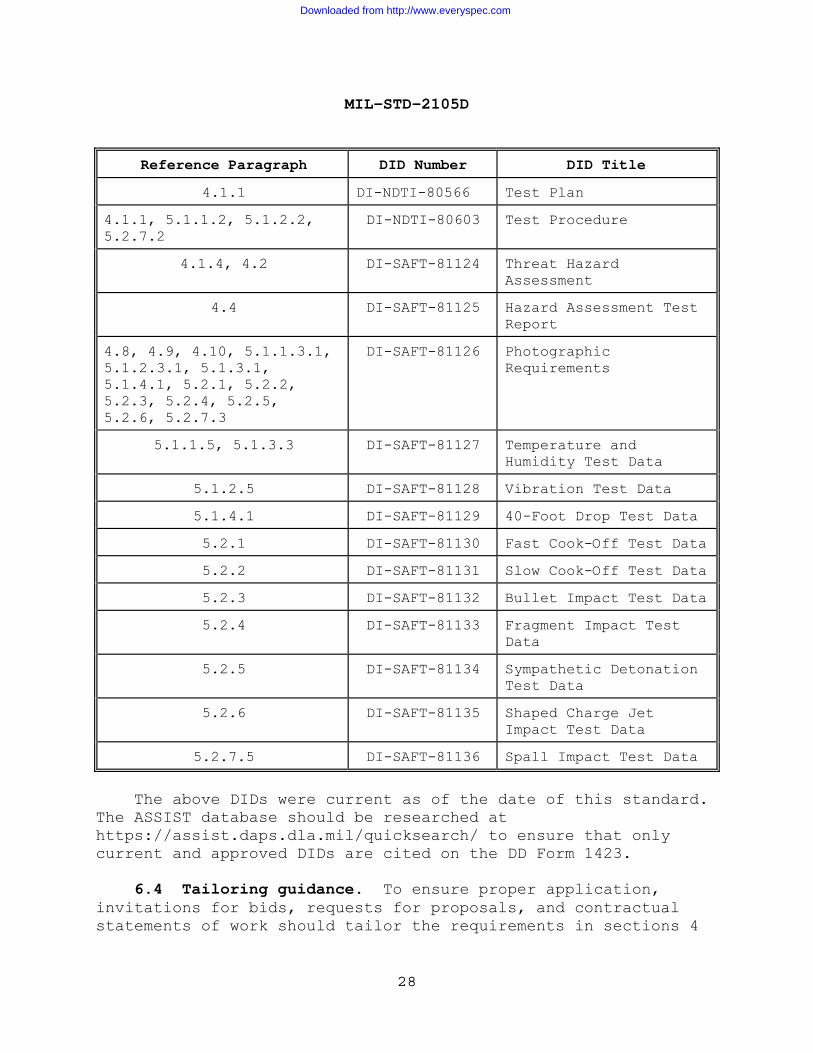
Reference Paragraph DID Number DID Title
4.1.1 DI-NDTI-80566 Test Plan
4.1.1, 5.1.1.2, 5.1.2.2, 5.2.7.2
DI-NDTI-80603 Test Procedure
4.1.4, 4.2 DI-SAFT-81124 Threat Hazard Assessment
4.4 DI-SAFT-81125 Hazard Assessment Test Report
4.8, 4.9, 4.10, 5.1.1.3.1, 5.1.2.3.1, 5.1.3.1, 5.1.4.1, 5.2.1, 5.2.2, 5.2.3, 5.2.4, 5.2.5, 5.2.6, 5.2.7.3
DI-SAFT-81126 Photographic Requirements
5.1.1.5, 5.1.3.3 DI-SAFT-81127 Temperature and Humidity Test Data
5.1.2.5 DI-SAFT-81128 Vibration Test Data
5.1.4.1 DI-SAFT-81129 40-Foot Drop Test Data
5.2.1 DI-SAFT-81130 Fast Cook-Off Test Data
5.2.2 DI-SAFT-81131 Slow Cook-Off Test Data
5.2.3 DI-SAFT-81132 Bullet Impact Test Data
5.2.4 DI-SAFT-81133 Fragment Impact Test Data
5.2.5 DI-SAFT-81134 Sympathetic Detonation Test Data
5.2.6 DI-SAFT-81135 Shaped Charge Jet Impact Test Data
5.2.7.5 DI-SAFT-81136 Spall Impact Test Data
The above DIDs were current as of the date of this standard. The ASSIST database should be researched at https://assist.daps.dla.mil/quicksearch/ to ensure that only current and approved DIDs are cited on the DD Form 1423. 6.4 Tailoring guidance. To ensure proper application, invitations for bids, requests for proposals, and contractual statements of work should tailor the requirements in sections 4
Downloaded from http://www.everyspec.com
MIL-STD-2105D
29
and 5 of this standard to exclude any unnecessary requirements. Contractual documents must specify the following: a. Ambient test item temperature if other than as specified (see paragraph 4.2.1). b. When a pre-test examination is not required (see paragraphs 4.8 and 5.1.1.2). c. The number of test items to be tested if other than as specified (see paragraph 5.1). 6.5 Submission of test reports and results. Submit copies of test reports and results to the following address for storage in the IM Hazard Classification Office (IMHCO)): Navy/Marine Corps—(for IM): Commanding Officer Naval Ordnance Safety & Security Activity Farragut Hall Attn: NOSSA, N85 3817 Strauss Ave., Suite 108 Indian Head, MD 20640-5151 6.6 Service review organizations. The following service contacts are responsible for the assessment of weapon safety and IM characteristics: Army - (for weapon safety): Director Chief, Safety Office
US Army Aviation and Missiles Command ATTN: AMSAM‐SF Redstone Arsenal, AL 35898‐5130
Army - (for IM): Commander U.S. Army AMRDEC Aviation & Missile Research, Development & Engineering Center Attn: RDMR-WDP-M Bldg. 7156
Downloaded from http://www.everyspec.com

MIL-STD-2105D
30
Redstone Arsenal, AL 35898-5249 Navy/Marine Corps - (for weapon safety): Commanding Officer Naval Ordnance Safety & Security Activity Farragut Hall Attn: NOSSA, N3 3817 Strauss Ave., Suite 108 Indian Head, MD 20640-5151 Navy/Marine Corps - (for IM): Commanding Officer Naval Ordnance Safety & Security Activity Farragut Hall Attn: NOSSA, N85 3817 Strauss Ave., Suite 108 Indian Head, MD 20640-5151 Air Force - (for weapon safety): AFSA/SEWV 9700 G Street Kirtland AFB, NM 87117-5670 Air Force - (for IM): ASC/YOX Eglin AFB, FL 32542-6808 6.7 Tests for hazard classification. The following tests referenced herein have potential application for hazard classification, but some specifics of testing may require approval by service review organizations and the DDESB prior to testing: 12-m (40-ft) drop Fast cook-off Slow cook-off Bullet impact Sympathetic reaction
Downloaded from http://www.everyspec.com
MIL-STD-2105D
31
6.8 Units of measurement and abbreviations. Units of measurement are expressed in metric or SI (Le Système International d'Unités). The corresponding English equivalent follows in parentheses. Standard abbreviations used throughout this document are as follows: Metric (SI) English C - degrees Celsius F - degrees Fahrenheit mm - millimeters in - inches m - meters ft - feet m/s - meters per second ft/s - feet per second Nm - newton meter lbfft - pound-force foot kPa - kilopascal (gauge) psig - pounds per square inch (gauge) 6.9 Subject term (key word) listing. Bullet impact test Shaped charge jet impact test Drop test Slow cook-off test Fast cook-off test Spall impact test Fragment impact test Sympathetic reaction test Humidity test Temperature test Insensitive munitions Vibration test Munitions, insensitive Safety test 6.10 International standardization agreements. Certain provisions of this standard are the subject of international standardization agreements. These are: MIL-STD-2105C NATO STANAG 12-m (40-ft) drop test 4375 Fast cook-off test 4240 Slow cook-off test 4382 Bullet impact test 4241 Sympathetic reaction test 4396 Fragment impact test 4496 Hazard assessment tests for munitions 4439 Shaped charge jet impact test 4526 When change notice, revision, or cancellation of this standard is proposed that will modify the international agreement concerned, the preparing activity will take
Downloaded from http://www.everyspec.com

MIL-STD-2105D
32
appropriate action through international standardization channels, including departmental standardization offices, to change the agreement or make other appropriate accommodations. 6.11 Changes from previous issue. Marginal notations are not used to identify changes with respect to the previous issue because of the extensiveness of the changes. Custodians: Preparing activity: Army - AR Navy - OS Navy - OS (Project SAFT-2011-001) Air Force - 11 Review activities: Army - TE Navy - AS NOTE: The activities listed above were interested in this document as of the date of this document. Since organizations and responsibilities can change, you should verify the currency of the information above using the ASSIST Online database at https://assist.daps.dla.mil.
Downloaded from http://www.everyspec.com