metric mil-std-1678-1 w/change 1 superseding...
TRANSCRIPT
METRIC
MIL-STD-1678-1 W/CHANGE 1 21 September 2011 SUPERSEDING MIL-STD-1678-1 28 May 2010
DEPARTMENT OF DEFENSE STANDARD PRACTICE
FIBER OPTIC CABLING SYSTEMS REQUIREMENTS AND MEASUREMENTS
(Part 1: DESIGN, INSTALLATION AND MAINTENANCE REQUIREMENTS)
(PART 1 OF 5 PARTS)
AMSC N/A AREA 60GP
Downloaded from http://www.everyspec.com
MIL-STD-1678-1 W/CHANGE 1
ii
FOREWORD 1. This Department of Defense Standard Practice is approved for use by the DLA Land and Maritime, Defense Logistics Agency, and is available for use by all Departments and Agencies of the Department of Defense. 2. Comments, suggestions or questions on this document should be addressed to DLA Land and Maritime, ATTN: VAT, Post Office Box 3990, Columbus, OH 43218-3990, or emailed to ([email protected]). Since contact information can change, you may want to verify the currency of this address information using the ASSIST Online database at https://assist.daps.dla.mil/. 3. This standard practice provides detailed information and guidance to personnel concerned with ensuring standardization of fiber optic cable topologies (optical fiber cabling and associated components) on military mobile vehicles used in air, land, and sea applications. In general, the requirements and methods specified herein are not identifiable to any specific mobile vehicle class or type, but are intended to standardize and minimize variations in requirements, test setups, test measurement procedures, test sample fabrication configurations, and other aspects that must be addressed for completeness. Where specified, constrains for usage or platform types will be listed. The term “platform” will be used to refer to the military mobile vehicles in general or, where designated, one particular class (such as “aircraft platform”) or one particular type within that class (such as “F-35”). 4. In order to provide flexibility in the use and update of the different aspects for requirements and methods, this standard practice is issued in five parts; as follows: Part 1: Design, maintenance, and installation requirements. This part addresses design requirements for platforms that use cable
harnesses as the means to transport data through optical fiber among communication network and end user equipment. Larger platforms that route trunk cables through cableways and drop cables to the end user (application equipment), can cite applicable requirements in Part 1 of the Standard Practice and augment them with use of MIL-HDBK-2051 and MIL-STD-2042 as appropriate. Surface ships and submarines are to use MIL-HDBK-2051 and MIL-STD-2042 in lieu of part 1 of this Standard Practice.
Part 2 Optical measurements. Part 2 of this standard addresses further details to refine or bound (constrain) the performance of
each optical test measurement addressed. The test methods, such as those in a TIA-455 series standard or military standard/specification, are cited already. This part of the standard practice augments the test method in the standard or specification to ensure consistency with setup and measurement procedure. This consistency minimizes variations when comparing data obtained from different test laboratories (including commercial, vendor, Government, and Government contractor).
Part 3 Physical, mechanical, environmental and material measurements. Part 3 of this standard addresses further details to
refine or bound (constrain) the performance of each physical, mechanical, environmental and material test measurement or inspection addressed. The test methods, such as those in a TIA-455 series standard or military standard/specification, are cited already. This part of the standard practice augments the test method to ensure consistency with setup, measurement procedure, data recording/analysis and other factors critical to conducting or evaluating test performance. This consistency minimizes variations when comparing data obtained from different test laboratories (including commercial, vendor, Government and Government contractor).
Part 4 Test sample preparation/fabrication requirements. Part 4 of this standard addresses further details to refine or bound
(constrain) the preparation and fabrication of test samples for the fiber optic components addressed. Fabrication methods, such as those in the Shipboard installation standard, MIL-STD-2042, or in the general series aircraft maintainer’s manual, NAVAIR 01-1A-505-4/T.O. 1-1A-14-4/TM 1-1500-323-24-4, are cited already. This part of the standard practice augments the fabrication method to ensure consistency of the test configuration
Downloaded from http://www.everyspec.com
MIL-STD-1678-1 W/CHANGE 1
iii
Part 5 Design phase and legacy measurements. Tests that are more unique to the design phase are addressed in Part 5 of this standard practice. Prequels for Part 2 of this standard practice contained other variants that are now excluded. These variants are now retained for informational purposes in Part 5. Also, Part 5 addresses some test methods cited in former DOD-STD-1678. The test methods cited in DOD-STD-1678 are considered obsolete; however, a few military specifications and commercial standards still refer to some of the test methods. These test methods are provided in this part of the standard with the recommended replacement method. These latter test methods are listed under the constraint that they be used only with the specific military specifications or commercial standards in which they are cited. The intent is to delete each DOD-STD-1678 test method from that standard practice in Part 5 once its reference from military specification or commercial standard is completed.
Downloaded from http://www.everyspec.com
MIL-STD-1678-1 W/CHANGE 1
iv
CONTENTS
PARAGRAPH PAGE 1. SCOPE 1 1.1 Scope 1 1.1.1 Applicability 1 2. APPLICABLE DOCUMENTS 2 2.1 General 2 2.2 Government documents 2 2.2.1 Specifications, standards and handbooks 2 2.2.2 Other Government documents, drawings and publications 2 2.3 Non-Government publications 2 2.4 Order of precedence 3 3. DEFINITIONS 4 3.1 General fiber optics terms 4 3.2 Acronyms 4 3.3 End user equipment 4 3.4 Fiber Optic Cable Plant (FOCP) 4 3.5 Fiber Optic Cable Topology (FOCT) 4 3.6 Local cable 4 3.7 Minimum bend diameter, fiber optic cable 4 3.8 Minimum bend diameter, fiber optic cable assembly 4 3.9 Platform 4 3.10 Platform class 4 3.11 Platform type 4 3.12 Reliability 4 3.13 Durability 4 4. GENERAL REQUIREMENTS 5 4.1 Consistent approach throughout system engineering process 5 4.1.1 System design considerations 5 4.2 Reduction of total ownership cost 5 4.3 Operating wavelength 6 4.4 Consensus of design requirements 6 5. DETAILED REQUIREMENTS 7 5.1 Cabling requirements 7 5.2 Cabling support requirements 7 5.3 Cabling implementation verification requirements 7 5.4 Cabling documentation requirements 7 6. NOTES 8 6.1 Intended use 8 6.2 Acquisition documents 8 6.3 Subject term (key word) listing 8 6.4 Changes from previous issue 8 6.5 Supersession data 8
Downloaded from http://www.everyspec.com
MIL-STD-1678-1 W/CHANGE 1
v
PARAGRAPH PAGE REQUIREMENTS Cabling requirements 1101 Fiber Optic Cabling Routing, Placement and Other Specific Design Practices 10 1102 Fiber Optic Cabling Components 22 1103 Fiber Optic Cable Repair 26 1104 Fiber Optic Cabling Labeling 29 1105 Fiber Optic Cabling Interface on Equipment Modules 38 Cabling support requirements 1201 Built-In-Test (BIT) 44 1202 Loss Budget Calculations 47 Cabling implementation verification requirements 1301 Optical Measurement Inspections 52 1302 End Face Geometry Inspection 55 1303 Fiber Optic Cabling Post Installation Inspection 58 1304 Fiber Optic Cabling Quality Conformance Inspection 60 Cabling documentation requirements 1401 Fiber Optic Cabling Technical Documentation 63 1402 Fiber Optic Cabling Management Documentation 65 1403 Fiber Optic Cable Harness Drawings 67
Downloaded from http://www.everyspec.com
MIL-STD-1678-1 W/CHANGE 1
1
1. SCOPE 1.1 Scope. Part 1 of this standard practice provides detailed design requirements for platforms that use cable harnesses as the means to transport data through optical fiber among communication network and end user equipment. 1.1.1 Applicability. These criteria apply to platforms in which the fiber optic topology (fiber cable plant, local cabling, and components to end used equipment such as WRA – weapons replaceable assembly, LRM – line replaceable module, LRU – line replaceable unit) is in the form of fiber optic harnesses. Larger platforms that route trunk cables through cableways and drop cables to the end user (application equipment), can cite applicable requirements in part 1 of the Standard Practice and augment with the use of MIL-HDBK-2051 and MIL-STD-2042 as appropriate. Surface ships and submarines, are to use MIL-HDBK-2051, MIL-STD 2052, and MIL-STD-2042 in lieu of Part 1 of this Standard Practice. These criteria are intended primarily for new construction; however, they are also applicable for conversions or alterations of existing platforms. The rapidly changing state of the art in fiber optic technology makes it essential that some degree of flexibility be exercised in enforcing this document. When there is a conflict between this document and the platform specification or contract, the platform specification or contract shall take precedence. Where platform design is such that the requirements herein cannot be implemented, users shall submit new requirements or modifications of existing requirements to consider for incorporation into this standard practice to: DLA Land and Maritime, ATTN: VAT, Post Office Box 3990, Columbus, OH 43218-3990, or emailed to ([email protected]).
Downloaded from http://www.everyspec.com
MIL-STD-1678-1 W/CHANGE 1
2
2. APPLICABLE DOCUMENTS 2.1 General. The documents listed in this section are specified in sections 3, 4, and 5 of this standard. This section does not include documents cited in other sections of this standard or recommended for additional information or as examples. While every effort has been made to ensure the completeness of this list, document users are cautioned that they must meet all specified requirements of documents cited in sections 3, 4, and 5 of this standard, whether or not they are listed. 2.2 Government documents. 2.2.1 Specifications, standards, and handbooks. The following specifications, standards, and handbooks form a part of this document to the extent specified herein. Unless otherwise specified, the issues of these documents are those cited in the solicitation or contract. DEPARTMENT OF DEFENSE STANDARDS MIL-STD-2042 - Fiber Optic Cable Topology Installation, Standard Methods for Naval Ships, Parts 1 to 6. MIL-STD-2052 - Fiber Optic System Design. DEPARTMENT OF DEFENSE HANDBOOKS MIL-HDBK-2051 - Fiber Optic Shipboard Cable Topology Design Guidance. (Copies of these documents are available online at https://assist.daps.dla.mil/quicksearch/ or from the Standardization Document Order Desk, 700 Robbins Avenue, Building 4D, Philadelphia, PA 19111-5094.) 2.2.2 Other Government documents, drawings, and publications. The following other Government documents, drawings, and publications form a part of this standard practice to the extent specified herein. Unless otherwise specified, the issues are those cited in the solicitation or contract. DEPARTMENT OF DEFENSE DRAWINGS NAVSEA Drawing 53711-8283255 - Termini, Fiber Optic, MIL-PRF-29504/4 and /5, Test Sample Configurations/Fabrication and Specific Methods/Practices. NAVAIR 01-1A-505-4/ - Aircraft Fiber Optic Cabling, Technical Manual, Installation and T.O. 1-1A-14-4/ Testing Practices. TM 1-1500-323-24-4 (A copy of this document is available online at: https://jswag.navair.navy.mil. At the home page select “Document Library” (on left side), then select the “Committee” folder, then “JFOWG” followed by the “Maintenance Documents” folder. If unable to access this Web Site, request an application by e-mail to NSWC DD Warfare Systems Department at: ([email protected].) 2.3 Non-Government publications. The following documents form a part of this document to the extent specified herein. Unless otherwise specified, the issues of these documents are cited in the solicitation or contract. AMERICAN NATIONAL STANDARDS INSTITUTE (ANSI) ANSI Z136.2 - Safe Use of Optical Fiber Communication Systems Utilizing Laser Diode and LED Sources. (Copies are available online at http://www.ansi.org or can be obtained from the American National Standards Institute, 1430 Broadway, New York, NY 10018-3308.)
Downloaded from http://www.everyspec.com
MIL-STD-1678-1 W/CHANGE 1
3
ELECTRONICS INDUSTRY ALLIANCE/TELECOMMUNICATIONS INDUSTRY ASSOCIATION TIA/EIA-440 - Fiber Optic Terminology. (Copies are available online at http://www.tiaonline.org/standards/catalog/index.cfm or from TIA, 2500 Wilson Boulevard, Suite 300, Arlington, VA 22201, USA, ATTN: Standards Department.) 2.4 Order of precedence. Unless otherwise noted herein or in the contract, in the event of a conflict between the text of this document and the references cited herein, the text of this document takes precedence. Nothing in this document, however, supersedes applicable laws and regulations unless a specific exemption has been obtained.
Downloaded from http://www.everyspec.com
MIL-STD-1678-1 W/CHANGE 1
4
3. DEFINITIONS 3.1 General fiber optics terms. Definitions for general fiber optics terms used in this standard practice are in accordance with TIA/EIA-440. Definitions for other terms as they are used in this standard practice are given in the following paragraphs. 3.2 Acronyms. The following acronyms are used in this standard practice: FOCP Fiber optic cable plant. FOCT Fiber optic cable topology. LRM Line replaceable module. LRU Line replaceable unit. WRA Weapons replaceable assembly. 3.3 End user equipment. This equipment is either the source or destination of an optical signal. This equipment can be a cabinet, case, panel, or device. The devices include WRA: Weapons replaceable assembly, LRM: Line replaceable module, and LRU: Line replaceable unit. 3.4 Fiber optic cable plant (FOCP). The FOCP is a subset of the FOCT that excludes cables within the WRA’s, LRM’s or LRU’s and their associated components. The FOCP consists of the backbone cabling run between transmitting and receiving network nodes on some platforms and on the outside of the bulkhead or electronic equipment on other platforms. 3.5 Fiber optic cable topology (FOCT). The FOCT is an integrated optical fiber distribution system that provides the optical interconnection between end user equipments. Included in the FOCT are the FOCP and the cable within the WRA, LRM, or LRU. 3.6 Local cable. A fiber optic cable run between end users. 3.7 Minimum bend diameter, fiber optic cable. The smallest diameter at which a fiber optic cable can be bent without degrading optical performance. The short-term bend diameter applies during handling and installing; the long-term bend diameter applies once the installation is completed. 3.8 Minimum bend diameter, fiber optic cable assembly. The smallest diameter at which a fiber optic cable assembly can be bent without degrading optical performance, or the diameter at which convoluted tubing in which fiber optic cable is run, can be bent without kinking the tube. The short-term bend diameter applies during handling and installing; the long-term bend diameter applies once the installation is completed. 3.9 Platform. A military mobile vehicle used in air, land, or sea applications. 3.10 Platform class. A general category of military mobile vehicles such as aircraft, aircraft fixed wing, aircraft rotary, truck, cargo truck, armored assault vehicle, ship, surface ship, or submarine. 3.11 Platform type. A specific military mobile vehicle such as an F-35 under aircraft or DDG-51 under ship. 3.12 Reliability. The probability that an item will perform in its intended function for a specific interval under stated conditions. 3.13 Durability. The length of a failure free or maintenance free operational period.
Downloaded from http://www.everyspec.com
MIL-STD-1678-1 W/CHANGE 1
5
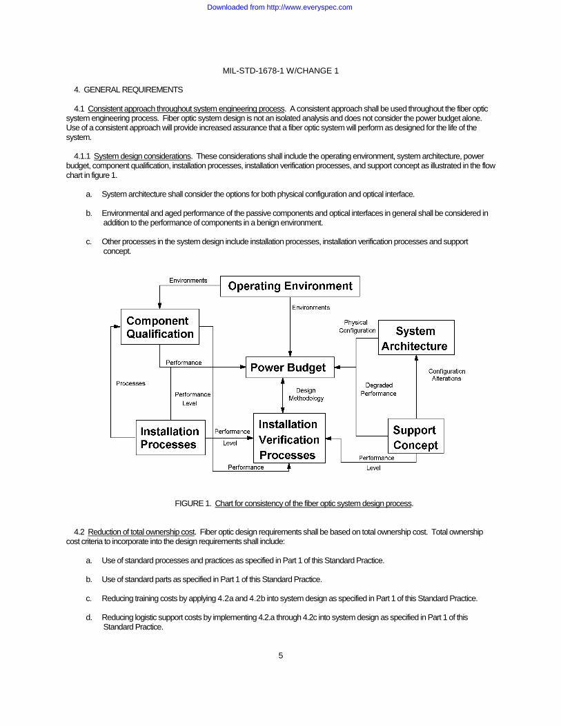
4. GENERAL REQUIREMENTS 4.1 Consistent approach throughout system engineering process. A consistent approach shall be used throughout the fiber optic system engineering process. Fiber optic system design is not an isolated analysis and does not consider the power budget alone. Use of a consistent approach will provide increased assurance that a fiber optic system will perform as designed for the life of the system. 4.1.1 System design considerations. These considerations shall include the operating environment, system architecture, power budget, component qualification, installation processes, installation verification processes, and support concept as illustrated in the flow chart in figure 1. a. System architecture shall consider the options for both physical configuration and optical interface. b. Environmental and aged performance of the passive components and optical interfaces in general shall be considered in
addition to the performance of components in a benign environment. c. Other processes in the system design include installation processes, installation verification processes and support
concept.
FIGURE 1. Chart for consistency of the fiber optic system design process.
4.2 Reduction of total ownership cost. Fiber optic design requirements shall be based on total ownership cost. Total ownership cost criteria to incorporate into the design requirements shall include: a. Use of standard processes and practices as specified in Part 1 of this Standard Practice. b. Use of standard parts as specified in Part 1 of this Standard Practice. c. Reducing training costs by applying 4.2a and 4.2b into system design as specified in Part 1 of this Standard Practice. d. Reducing logistic support costs by implementing 4.2.a through 4.2c into system design as specified in Part 1 of this
Standard Practice.
Downloaded from http://www.everyspec.com
MIL-STD-1678-1 W/CHANGE 1
6
e. Use practices that improve reliability, maintainability, durability, performance, producibility, quality, and safety over the entire expected service life of the platform.
(1) Laser safety precautions. The classification of a laser is based on the ability of the optical beam to cause damage to
the eye. Under normal operating conditions, the laser diode found in an optical fiber communication system (OFCS) is inherently an eye safe system; but, when an optical fiber connection is broken and optical viewing instruments are used, it is possible that hazardous energy can enter the eye. For this reason, four service group hazard classes have been devised to indicate the degree of hazard and required hazard control measures. Refer to ANSI Z136.2 for a full technical definition. Refer to subordinate work package 004 01 of NAVAIR 01-1A-505-4/T.O. 1-1A-14-4/TM 1-1500-323-24-4 for a laser safety refresher summary.
(2) Fiber optic safety precautions. The fiber optic safety precautions listed in subordinate work package 004 01 of
NAVAIR 01-1A-505-4/T.O. 1-1A-14-4/TM 1-1500-323-24-4 shall apply. f. Use practices that ensure interoperability of fiber optic components and systems among platform types and classes. 4.3 Operating wavelength. Unless otherwise specified, the default operating wavelengths in 4.3.1 shall be specified as the standard transmission wavelength for the platform. Where feasible, wavelength of operation shall be standardized for each class of platform (see 3 under foreword). 4.3.1 Default. System shall be designed to operate at a nominal wavelength of either 850 nanometers (nm) for multimode optical fibers and at 1,550 nm for single mode optical fibers. 4.3.2 Alternative. System shall be designed to operate at a nominal wavelength of either 1,300 nanometers (nm) for multimode optical fibers and at 1,310 nm for single mode optical fibers. Other wavelengths of operation may be specified, but are less preferred. 4.4 Consensus of design requirements. The Joint Fiber Optic Working Group (JFOWG) shall be the means to reach consensus on standardization of new/revised design requirements, identify new requirements and new technologies that permit its rapid introduction, and provide those requirements to update Part 1 of this Standard Practice.
Downloaded from http://www.everyspec.com
MIL-STD-1678-1 W/CHANGE 1
7
5. DETAILED REQUIREMENTS 5.1 Cabling requirements. Requirements shall be implemented as specified in 5.1.1 through 5.1.4. 5.1.1 Cabling installation routing and specific practices. System design shall be performed to Requirement 1101. 5.1.2 Fiber optic cabling components. System design shall be performed to Requirement 1102. 5.1.3 Fiber optic cable repair. System design shall be performed to Requirement 1103 5.1.4 Fiber optic cabling labeling. System design shall be performed to Requirement 1104 5.2 Cabling support requirements. Requirements shall be implemented as specified in 5.2.1 and 5.2.2. 5.2.1 Built-In-Test (BIT). System design shall be performed to Requirement 1201. 5.2.2 Loss budget calculation. System design shall be performed to Requirement 1202. 5.3 Cabling implementation verification requirements. Requirements shall be implemented as specified in 5.3.1 through 5.3.4. 5.3.1 Optical measurements inspection. System design shall be performed to Requirement 1301. 5.3.2 End face geometry inspection. System design shall be performed to Requirement 1302. 5.3.3 Fiber optic cabling post installation inspection. System design shall be performed to Requirement 1303. 5.3.4 Fiber optic cabling conformance inspection. System design shall be performed to Requirement 1304. 5.4 Cabling documentation requirements. Requirements shall be implemented as specified in 5.4.1 through 5.4.3. 5.4.1 Fiber optic cabling technical documentation. System design shall be performed to Requirement 1401. 5.4.2 Fiber optic cabling management documentation. System design shall be performed to Requirement 1402. 5.4.3 Fiber optic cable harness drawing. System design shall be performed to Requirement 1403.
Downloaded from http://www.everyspec.com
MIL-STD-1678-1 W/CHANGE 1
8
6. NOTES (This section contains information of a general or explanatory nature that may be helpful, but is not mandatory.) 6.1 Intended use. The design requirements depicted in this standard practice are intended primarily for new construction; however, they are applicable for conversion or alteration of existing platforms. 6.2 Acquisition requirements. Acquisition documents should specify the following: Title, number, and date of this standard practice. 6.3 Subject term (key word) listing. Design requirements Fiber optic cabling 6.4 Change notations. The margins of this specification are marked with vertical lines to indicate modifications generated by this change. This was done as a convenience only and the Government assumes no liability whatsoever for any inaccuracies in these notations. Bidders and contractors are cautioned to evaluate the requirements of this document based on the entire content irrespective of the marginal notations. 6.5 Supersession data. The five parts of MIL-STD-1678 replace superseded DOD-STD-1678 with completely new fiber optic requirements and measurements. With the exception of some legacy material in Part 5 of MIL-STD-1678, none of the fiber optic test and measurement material comprising superseded DOD-STD-1678 has been included. With the exceptions noted in Part 5 of this standard practice, this standard practice should be applied in lieu of the legacy methods in superseded DOD-STD-1678.
Downloaded from http://www.everyspec.com

MIL-STD-1678-1 W/CHANGE 1
9
CABLING REQUIREMENTS
(1101-1104)
Downloaded from http://www.everyspec.com
MIL-STD-1678-1 W/CHANGE 1
10
REQUIREMENT 1101
FIBER OPTIC CABLING ROUTING, PLACEMENT AND OTHER SPECIFIC DESIGN PRACTICES
1. Purpose. This requirement establishes distinct criteria for specific routing, placement, and other design practices of fiber optic cabling components and assemblies, consisting of cables, cable bundles, and cable harnesses (hereinafter collectively referred to as cabling). This requirement is intended for developmental, prototype, production, rework, and modification programs on military platform fiber optic cable assemblies. 2. Applicable documents. 2.1 General. The documents listed in this section are specified in sections 3, 4, and 5 of this standard practice. This section does not include documents cited in other sections of this standard practice or recommended for additional information or as examples. While every effort has been made to ensure the completeness of this list, document users are cautioned that they must meet all specified requirements of documents cited in sections 3, 4, and 5 of this standard practice, whether or not they are listed. 2.2 Non-Government publications. The following documents form a part of this document to the extent specified herein. Unless otherwise specified, the issues of these documents are cited in the solicitation or contract. SOCIETY OF AUTOMOTIVE ENGINEERS (SAE International) SAE AS50881 - Wiring, Aerospace Vehicle. (Copies are available from http://www.sae.org or SAE International, 400 Commonwealth Drive, Warrendale, PA 15036-0001.) 2.3 Order of precedence. Unless otherwise noted herein or in the contract, in the event of a conflict between the text of this document and the references cited herein, the text of this document takes precedence. Nothing in this document, however, supersedes applicable laws and regulations unless a specific exemption has been obtained. 3. Definitions. 3.1 Fiber optic cabling. Fiber optic cabling is a term used to include single fiber cable, multiple fiber cable, fiber optic cable bundles, and fiber optic cable harnesses. The (optical) fiber is the optical conduit or waveguide transmission media, whereas metallic conductor (wire) is used in an electrical cable. Cable structure is added to make the fibers easier to handle and maintain. The fiber is a thin piece of glass (with a diameter usually around 125 micrometers) that contains and transports the light signals. 3.2 Wire. “A usually pliable metallic strand or rod made in many lengths and diameters, sometimes clad and often electrically insulated, used chiefly for structural support or to conduct electricity.” Source: American Heritage Dictionary, College Edition. 4. Installation. Cabling shall be installed as specified in SAE AS 50881. 5. Guidance. Guidance for implementation from lessons learned (see 6.1) is documented in appendix A of this Requirement. 6. Notes. 6.1 Lessons learned. 6.1.1 Cleaning. 6.1.1.1 Cleaning is paramount. Current military maintainer experience has been that about 80 percent of fiber optic maintenance actions are traced back to cleaning at fiber optic connection interfaces. Use of an inspect-clean-inspect process (such as the one found in the General Series Maintenance Manual, NAVAIR 01-1A-505-4/T.O. 1-1A-14-4/TM 1-1500-323-24-4) ensures proper operation once maintenance action is complete.
REQUIREMENT 1101
Downloaded from http://www.everyspec.com
MIL-STD-1678-1 W/CHANGE 1
11
6.1.1.2 Use of dummy stowage receptacles. Install dummy stowage receptacles for securing connector plug end of cabling adjacent to equipment. This avoids contamination, which might be difficult to clean, during storage.
6.1.1.3 Minimize termini contamination. Use dust covers and dummy connector receptacles as the means to minimize termini contamination when a multiple termini connector is unmated. 6.1.1.4 Segregation of termini and contacts. Segregation of fiber optic termini from electrical contacts reduces cleaning issues and minimizes occurrences of applying preservatives to connectors with fiber optic termini. 6.1.2 Selection. 6.1.2.1 Preferred construction of cable harness or protection for cable runs. Use convoluted tubing as the means to protect the fiber optic cables and cable bundles in both a protected cable harness configuration and for cabling runs within an open cable harness. Use clear or semi-transparent convoluted tubing. Use convoluted tubing made from FEP (fluorinated ethylene propylene) for general use. Use convoluted tubing made from PEEK (polyether-ether-ketone) for intra cabin applications requiring low smoke and zero halogen fire emissions. 6.1.2.2 Use proven components and construction (see Requirement 1102). Use of untried, developmental components has repeatedly shown failure mechanisms and problems already addressed in the preferred components (see Requirement 1102). 6.1.2.3 Drainage holes in convoluted tubing. Placement of drainage holes in convoluted tubing after installation of fiber optic cable bundles results in significant fiber breakage. If drainage holes are required, pre-perforated convoluted tubing is preferred. 6.1.3 Layout. 6.1.3.1 Constraints on redundancy. Redundant paths of fiber optic cabling must be routed in separate cable harnesses versus in the same fiber optic cable bundle. Risk of signal loss is reduced when cause of fiber breakage may extend to multiple fibers in the same bundle or routing path. 6.1.3.2 Maintenance actions. Design system to minimize removal of equipment that requires mating and de-mating of fiber optic connectors (design system to minimize fiber optic connector mating and de-mating). 6.1.3.3 Use of maintenance breaks. Use of maintenance breaks near network equipment and end user equipment allows remove and replace subassemblies at locations likely to see high maintenance and corresponding high likelihood of maintenance induced failures. Making these maintenance breaks a common length minimizes the number of replacement configurations that need to be logistically supported. 6.1.4 Placement. 6.1.4.1 Minimize slack in cabling. Reduced cable slack discourages fiber optic cabling from being used as hangers, hand-holds, and other practices detrimental to optical fiber survivability in addition to minimizing chances of fiber breakage/fatigue caused by operational environmental and mechanical stresses. 6.1.4.2 Support cabling in areas requiring movement. Applications requiring movement (such as shifting or sliding) in the fiber optic cabling must have the cabling mounted to a movable support versus allowing a length of unsupported cabling. Equipment mounts requiring sliding or shifting of fiber optic cabling for installation or maintenance is not preferred and should be minimized. 6.1.4.3 Segregate optical fiber. Mixing of electrical conductors with optical fibers in the same cable bundle or cable harness does not allow for easy identification, maintenance, and handling of the fiber optic cables. This lack of identification results in increase breakage of the fiber optic cables during initial installation and maintenance.
REQUIREMENT 1101
Downloaded from http://www.everyspec.com
MIL-STD-1678-1 W/CHANGE 1
12
6.1.4.4 Use a remove and replace repair strategy for optical fiber. The preferred repair method is to use a remove and replace repair strategy rather than repair insitu (such as with a splice). When a splice is used, the portion of the cable after the break is removed (including its end terminus) and replaced with a prefabricated terminus pigtail. This avoids termination (application of a terminus including curing and polishing) on the aircraft. Fiber breaks occur almost always within 304.8 mm (12 inches) from the connector. Prioritizing of repair strategies are as follows: (1) remove and replace of short segments (i.e., maintenance breaks), (2) remove and replace fiber within convoluted tubing, (3) perform splicing. 6.1.5 Personnel considerations. 6.1.5.1 Follow laser safety and fiber optic handling instruction. Installation/maintenance personnel training must include laser safety and fiber optic handling to mitigate risks such as eye and skin damage.
6.1.5.2 Follow the common maintenance procedures. Follow common maintenance procedures such as in the General Series Maintenance Manual, NAVAIR 01-1A-505-4/T.O. 1-1A-14-4/TM 1-1500-323-24-4. System design consideration shall be based on these or equivalent procedures. 6.1.5.3 Personnel information overload. Standardization can minimize the logistics footprint and reduce the strain on the maintainer by minimizing the total number of variations which a maintainer has to remember as well as execute with proficiency potentially over long periods of disuse. Standardization can extend to installation and maintenance practices and the parameters they use (such as cable bend diameter). Stated succinctly - use the KISS principle (Keep It Simple and Segmented). 6.1.5.4 Personnel proficiency. Time to repair a failure is greatly reduced by providing a remove and replace maintenance strategy that quickly identifies the replaceable unit (such as fiber segment) eliminating the need for complicated troubleshooting or in situ repair. 6.2 Intended use. On these platforms, the fiber optic cable assemblies intended to be inspected include (1) cable harnesses, (2) equipment (electronic module/package) such as a WRA, LRM or LRU with internal fiber optics, (3) circuit card modules and assemblies with internal fiber optics, (4) fiber optic test jumpers, and (5) other miscellaneous cabling. 6.2.1 Routing and specific installation practices. Field practices for routing and installation are implemented to WP 012 of NAVAIR 01-1A-505-4/T.O. 1-1A-14-4/TM 1-1500-323-24-4 for aircraft platforms. These same practices can be adopted or tailored for other platforms.
REQUIREMENT 1101
Downloaded from http://www.everyspec.com
MIL-STD-1678-1 W/CHANGE 1
13
REQUIREMENT 1101
APPENDIX A
Guidance For Implementation of Lessons Learned. A.1 Purpose. This appendix addresses routing and other specific practices to implement based on lessons learned from field/fleet maintainers. A.2 Applicable documents. A.2.1 General. The documents listed in this section are specified in sections A3, A4, and A5 of this standard practice. This section does not include documents cited in other sections of this standard or recommended for additional information or as examples. While every effort has been made to ensure the completeness of this list, document users are cautioned that they must meet all specified requirements of documents cited in sections A3, A4, and A5 of this standard practice, whether or not they are listed. A.2.2 Government documents. A.2.2.1 Specifications, standards, and handbooks. The following specifications, standards, and handbooks form a part of this document to the extent specified herein. Unless otherwise specified, the issues of these documents are those cited in the solicitation or contract. COMMERCIAL ITEM DESCRIPTIONS A-A-52081 - Tape, Lacing and Tying, Polyester. A-A-52083 - Tape, Lacing and Tying, Glass. A-A-59569 - Braid, Wire (Copper, Tin-Coated, Silver-Coated, or Nickel Coated, Tubular. Or Flat) (Copies of this document are available online at https://assist.daps.dla.mil/quicksearch or from the Standardization Document Order Desk, 700 Robbins Avenue, Building 4D, Philadelphia, PA 19111-5094.) DEPARTMENT OF DEFENSE SPECIFICATIONS MIL-PRF-24623 - Splice, Fiber Optic Cable, General Specification for (Metric). MIL-PRF-29504 - Termini, Fiber Optic Connectors, Removable, General Specification for. MIL-PRF-28876 - Connectors, Fiber Optic Circular, Plug and Receptacle Style, Multiple Removable Termini, General Specification for. MIL-PRF-64266 - Connectors, Fiber Optic, Circular, Plug and Receptacle Style, Multiple Removable Genderless Termini, Environment Resisting General Specification For MIL-C-83522 - Connectors, Fiber Optic, Single Termini, General Specification for. DEPARTMENT OF DEFENSE STANDARDS MS35489 - Grommets, Synthetic and Silicone Rubber, Hot-Oil and Coolant Resistant. (Copies of these documents are available online at https://assist.daps.dla.mil/quicksearch/ or from the Standardization Document Order Desk, 700 Robbins Avenue, Building 4D, Philadelphia, PA 19111-5094.) A.2.2.2 Other Government documents, drawings, and publications. The following other Government documents, drawings, and publications form a part of this document to the extent specified herein. Unless otherwise specified, the issues of these documents are those cited in the solicitation or contract. NAVAIR 01-1A-505-4/ - Technical Manual, Installation and Testing Practices, Aircraft Fiber Optic T.O. 1-1A-14-4/ Cabling. TM 1-1500-232-24-4
REQUIREMENT 1101
Downloaded from http://www.everyspec.com
MIL-STD-1678-1 W/CHANGE 1
14
APPENDIX A
NAVSEA Drawing 7613069 - JFOWG Recommended Fiber Optic Support Equipment List, Aircraft Applications (Copies of these documents are available online at: https://jswag.navair.navy.mil. At the home page select “Document Library” (on left side), then select the “Committee” folder, then “JFOWG” followed by the “Maintenance Documents” folder. If unable to access this Web Site, request an application by e-mail to NSWC DD Warfare Systems Department at: ([email protected].) A.2.2.3 Non-Government publications. The following documents form a part of this document to the extent specified herein. Unless otherwise specified, the issues of these documents are cited in the solicitation or contract. AEROSPACE INDUSTRIES ASSOCIATION (AIA) NAS43 - Spacer, Sleeve – Screw and Bolt NAS813 - Cap - Protective, Electrical Connector NAS820 - Plug - Protective, Electrical Connector NASM22529 - Grommet, Edging. (Copies of these documents can be obtained online at http://www.aia-aerospace.org or from Aerospace Industries Association of America, 1250 Eye Street, N. W., Suite 1200, Washington, DC, 20005-3924.) SOCIETY OF AMERICAN ENGINEERS INTERNATIONAL (SAE INTERNATIONAL) SAE AS21919 - Clamp, Loop Type, Cushioned, Support-FSC 5340. SAE AS23190 - Straps, Clamps, and Mounting Hardware, Plastic and Metal for Cable Harness Tying and Support. (Copies of these documents can be obtained online at http://www.sae.org or from SAE International World Headquarters, 400 Commonwealth Drive, Warrendale, PA 15096-0001.) A.2.3 Order of precedence. Unless otherwise noted herein or in the contract, in the event of a conflict between the text of this document and the references cited herein, the text of this document takes precedence. Nothing in this document, however, supersedes applicable laws and regulations unless a specific exemption has been obtained. A.3 Definitions. A.3.1 Bend diameter, minimum, short-term. The short-term bend diameter applies during handling and installing. The short-term bend diameter may be different for simplex tight buffer cable, for simplex loose tube cable, and for convoluted tube or conduit. A.3.2 Bend diameter, minimum, long-term. The long-term bend diameter applies to the completed installation. The long-term bend diameter may be different for simplex, tight buffer cable, for simplex, loose tube cable, and for convoluted tube or conduit. A.3.3 Cable, loose tube. A fiber optic cable design is one configured with one or more optical fibers fitted loosely within a tube, giving the optical fibers freedom to move. This mobility and isolation from the tube minimizes the effects of external forces on the performance of the link. The isolation allows cable expansion and contraction with temperature independent of the optical fibers. A.3.4 Cable, tight buffer. A fiber optic cable design is one configured with an additional protective coding (additional buffer layer) is applied directly over a coated (buffered) fiber. Buffer material helps preserve the fiber’s inherent strength and provides increased mechanical protection. A tight buffer cable allows cable placement in tighter bends, more roughed handling (such as better crush and impact resistance).
REQUIREMENT 1101
Downloaded from http://www.everyspec.com
MIL-STD-1678-1 W/CHANGE 1
15
APPENDIX A A.3.5 Chafing. Repeated motions between cabling components, between cabling and equipment, between cabling and the structure that result in wear causing mechanical failure, degraded or complete loss of the optical signal. Wear is the result of rubbing, excessive twisting or bending. Also, chafing may be defined in terms of poor installation practices. Chafing includes poor clamping, poor lacing, and poor routing. Cabling must be routed, clamped, and laced to prevent any contact with equipment or structures. A.3.6 End-to-end cabling path (fiber optic). The path light travels from the transmitter to the receiver. This path includes the connections up to the transmitting device, connections up to the receiving device, and one or more sections of fiber optic cable (such as one or more single segment, fiber optic cable harnesses). A.3.7 Fiber optic cable bundle. Single fiber cables grouped together and secured by lacing tape. The cable bundle can be placed in convoluted tubing, used in various protected harness configurations or used as is in an open cable harness configuration. A.3.8 Hybrid cables. Cables that contain both optical fibers and metallic conductors. A.3.9 Maintenance breaks. Short pieces of replaceable cable assembly that are used between the WRA, LRM, or LRU and the cable harness where the cabling is most susceptible to breakage. A.3.10 Mixed fiber cables. Cables that contain more than one size or type of optical fiber. A.3.11 Primary supports. Supports used to carry the weight and secure the fiber optic cable in its intended position by the use of metal cushion clamps shall be in accordance with AS21919 or AS23190 (see A.4.4.1.1). A.3.12 Secondary supports. Supports used to secure the cabling between primary supports and assist in carrying the weight. Lacing tape is used to provide the secondary support (see A.4.4.2.1). A.4 Routing. A.4.1 Externally induced loadings. Installed cable shall be routed to prevent axial, lateral, and torsion loads from being applied. A.4.1.1 Maintenance and inspection. Fiber optic cabling shall be accessible for maintenance and inspections without the disturbance of hydraulic lines, other fluid lines, or where feasible, electrical wiring (see A.4.7). A.4.1.2 Machinery removal. Fiber optic cabling route shall be located so that optical fiber cables will not be disturbed by disassembly or removal of machinery, including the removal of bolted or welded equipment removal plates. A.4.2 Cable slack. Sufficient cable slack shall be provided to perform required maintenance, to allow full extension of any vibration isolators or shock mounts, and prevent cable strain at points of bending and clamping. A.4.2.1 Connector ends. Cable slack at the connector ends of the cabling (slack from the last primary support and the connector end) shall allow the cabling to extend from 12.7 mm (.5 inch) to a maximum of 25.4 mm (1 inch) beyond the point required for mating the connector. Drip loops, or additional cable slack for other means, shall not be provided at connector ends of the cabling. A.4.3 Redundancy. A.4.3.1 Separate routing for different operating conditions. For essential equipment in which there are separate normal and emergency operating conditions, the cable shall be routed separately for each of these two conditions.
REQUIREMENT 1101
Downloaded from http://www.everyspec.com
MIL-STD-1678-1 W/CHANGE 1
16
APPENDIX A A.4.3.2 Routing in separate cable harnesses. For networks that use dual or multiple redundant data transmission paths, the redundant cabling shall be routed to prevent loss of transmission along one data transmission path from preventing transmission along the other path or paths. This shall be done in separate cable harnesses. If an exception is approved, this shall be done running the cabling in separate cable bundles within the same cable harness. A.4.3.3 Routing in Severe Wind and Moisture Problems (SWAMP) areas. Optical fiber cable shall not be run through SWAMP areas unless such routing is necessary to provide survivability through redundant signal paths. In such cases, suitable optical fiber and suitable cable protection (to act as a moisture barrier) shall be provided. A.4.3.4 Separation intervals. Redundant signal paths shall have these cables routed to separate network equipment, wherever practical. A.4.3.4.1 General guidance. The cabling interconnecting network equipment and network equipment to end user equipment shall be separated in the athwart (side-to-side) platform direction to the maximum extent possible and vertically by this same general guidance. An optimal cable routing scheme is one designed to provide a quadrangular pattern to allow maximum athwart platform and vertical separation of cables for systems requiring alternate signal paths for reliability and survivability. A.4.3.4.2 Equipment. Redundant local cable runs shall be separated for survivability as described herein except when they are within 1 m (3 ft) of the equipment. A.4.3.4.3 Wheel well applications. Unless otherwise specified for wheel well applications, convoluted tubing shall be used to protect cables or cable bundles and shall be used as part of the construction of cable harnesses. Restrictions on drainage holes for convolution tubing used in fiber optic cabling applications shall conform to A.5.6.2. If convoluted tubing is not used, then an alternative means such as abrasion resistant tape or other type outer tubing shall be used. A.4.3.4.4 Movable surfaces. Cabling shall be routed so that there is a twist instead of bend across hinges. Minimum separation between cabling and movable surfaces throughout the complete range of movement shall be at least 12.7 mm (.5 inch). A.4.3.4.5 Fluid lines. Cabling shall be routed above tubing or piping carrying fluid (both liquid and gases). Separation distance of 12.7 mm (.5 inch) or greater shall be maintained. Where this requirement for routing separation cannot be achieved, requirements for exceptions shall be developed. Where cabling must be routed below tubing or piping carrying fluids, it shall be routed on an angle with, and not parallel, to the tubing or piping. Unless the cabling is in a rigid conduit or a barrier is placed between the cabling and the tubing or piping carrying fluid, a separation distance of 12.7 mm (.5 inch) or greater shall be maintained. A.4.3.4.6 Fuel tanks. Cabling specified in Requirement 1102 shall not be routed through or used inside fuel tanks unless enclosed in a suitable conduit or other covering rated for continuous immersion in fuel. Components specified in Requirement 1102 are not intended for use in long term, fluid immersion applications, in general, and for use in fuel tanks specifically. A.4.4 Supports for routing cabling. A.4.4.1 Primary supports. Metal cushion clamps shall be the only means used to provide primary support to the cabling. A.4.4.1.1 Type. Metal cushion clamps shall be the means to provide primary support for the cabling, cable bundles, and cable harnesses. Metal cushion clamps shall conform to AS21919 or to AS23190. Band and cushion material combination codes CH and CJ are preferred for metal cushion clamps conforming to AS21919. Metal cushion clamps to AS23190 shall be the ones conforming to AS23190/4. A.4.4.1.2 Clamping intervals. Spacing intervals between primary supports shall not exceed 60.96 cm (24 inches). When the cabling, cable bundles or harness is a part of or placed in rigid tubing/conduit, then spacing intervals may be extended, but shall not exceed 106.68 cm (42 inches).
REQUIREMENT 1101
Downloaded from http://www.everyspec.com
MIL-STD-1678-1 W/CHANGE 1
17
APPENDIX A A.4.4.1.3 Use of standoffs for cable deflections allotments. Standoffs (also referred to as spacers) shall conform to NAS43. The depth of these standoffs shall be as short as practicable to allow a 12.7 mm (.5 inch) cable deflection without contacting the structure or mounting surface. A.4.4.2 Secondary supports. Lacing tape shall be the only means used to provide secondary support to the cabling. Lacing tape used as secondary supports is also referred to as tying tapes, lacing ties, or ties. The term "spot ties" becomes appropriate when lacing tape is used to separate a number of fiber optic cables or cable bundles within a cable harness or convoluted tubing (as a separator and not a means to secure). A.4.4.2.1 Type. Lacing tape shall conform to finish C, tying tape, sizes 2 or 3, in accordance with A-A-52083, for use in low to high vibration and/or high temperature environments (glass tying tape), or with A-A-52081, for use in only low vibration environments (polyester tying tape). A.4.4.2.2 Lacing intervals. Where the primary supports are more than 30.48 cm (12 inches) apart, lacing (space) ties shall be placed as secondary supports 30.48 cm (12 inches) or less apart. Distance between secondary supports shall be 76 mm (3 inches) for cabling installed in flight-testing applications. For an application, reference may be made to NAVAIR 01-1A-505-4/T.O. 1-1A-14-4/TM 1-1500-323-24-4 WP 010 00 paragraph 65. A.4.4.2.3 Lacing process for secondary support. The process to apply lacing tape to cabling for a secondary support shall be as specified below. First tie a clove hitch with the lacing tape followed by a square knot. Complete the second part of the square knot with an extra loop. Trim the free ends of the lacing ties to 9.53 mm (.375 inch) minimum. The lacing shall be snug, not clinched tight, so that the lacing does not locally stress the cable causing possible short or long term failure to the cabling. A.4.4.2.4 Lacing intervals at a mechanical splice. One lacing tie shall be placed 12.7 mm (.5 inch) from the middle of the mechanical splice along the longitudinal axis (z axis). A second lacing tie shall be placed 12.7 mm (.5 inch) from the middle of the mechanical splice from the other end. If the middle of the mechanical splice is affixed to a cable clamp, then place the lacing ties on the mechanical splice prior to fastening the cable clamp (primary support). Affixing the mechanical splice in the middle of/underneath a cable clamp is less preferred and shall be done only if the location does not provide an alternative solution. A.4.4.2.5 Continuous lacing. Continuous lacing shall not be used either for the secondary support of fiber optic cabling or for other applications (such as separation of cable bundles) on fiber optic cabling. A.4.5 Anti-chafing measures. Measures shall be taken to prevent chafing due to repeated motions (rubbing, excessive twisting or bending) between cabling components, between cabling and equipment (including at edges), between cabling and the structure (including at edges) that result in wear causing mechanical failure or degraded or complete loss of the optical signal. Measures taken to prevent chafing shall include proper routing, clamping as defined in A.3 and as specified along with other measures including those specified in A.4.4, A.4.5.1, A.4.5.2, and A.5.5. A.4.5.1 Use of convoluted tubing. Convoluted tubing shall conform to Requirement 1102. Also, refer to subordinate Work package WP 011 01 of NAVAIR 01-1A-505-4/T.O. 1-1A-14-4/TM 1-1500-323-24-4. A.4.5.2 Routing through cutouts. When cables, cable bundles and cable harnesses are routed through cutouts in the platform structure, then clamps and grommets shall be used as an anti-chafing measure. A.4.5.2.1 Metal cushion cable clamps. Clamps used shall be the same as the primary supports specified in A.4.5.
REQUIREMENT 1101
Downloaded from http://www.everyspec.com
MIL-STD-1678-1 W/CHANGE 1
18
APPENDIX A A.4.5.2.2 Grommets. Grommets shall be used when the radial distance between the cabling and the structure or equipment has a separation of 9.53 mm (.375 inch) or less. Either donut grommets or caterpillar grommets shall be used. When the donut grommet is split and for caterpillar grommets, the split shall be a diagonal cut that leaves a gap at the split ends no wider than 1.60 mm (.063 inch). The gap in the grommet shall be located opposite to the side cabling deflection is most likely to occur. A.4.5.2.2.1 Donut grommets. Donut grommets shall conform to MS35489. A.4.5.2.2.2 Caterpillar grommets. Caterpillar grommets shall conform to NASM22529. These caterpillar grommets shall not be used on holes sizes in which the diameter is less than 50.8 mm (2 inches). A.4.6 Use of maintenance breaks (see A.3.9). A.4.6.1 Locations. Maintenance breaks shall be used to provide remove and replace subassemblies at locations likely to see high maintenance and corresponding high likelihood of maintenance induced failures. A.4.6.2 Cabling length. Cabling for the maintenance breaks shall be between 152.4 mm (6 inches) to 457.2 mm (18 inches). Longer lengths are permitted if needed to meet the other installation requirements in Requirement 1101. A recommended common length is preferred to minimize the number of replacement configurations that need to be logistically supported. A.4.7 Maintenance actions. A.4.7.1 Equipment removal. Cable routing shall be designed to minimize the requirement to mate and de-mate fiber optic connectors for the removal of equipment. A.4.7.2 Other maintenance. Cable routing shall be designed to minimize the requirement to mate and de-mate fiber optic connectors to facilitate maintenance of other systems or equipment. A.4.7.3 No disturbance of structural bonds. Routing shall be designed such that repair does not require disturbing any riveted or bonded attachments. A.4.7.4 Maintenance environment. Maintenance actions involving fiber optic components shall be capable of being performed within the environmental constraints specified in paragraph 4.3, Requirement 1102 of MIL-STD-1678-1. A.5 Specific practices. Installation shall be performed in accordance with A.5.1 through A.5.11. A.5.1 Minimum bend diameter, short term. Minimum short term bend diameter shall not be exceeded during handling and installation. A.5.1.1 Cabling. Unless otherwise specified in the particular military standard or specification for the cabling, minimum bend diameter shall not exceed 8 times the cable diameter (four times the cable diameter if working in terms of cable bend radius). For loose tube cabling, the requirement specified for tubing shall be used in lieu of cabling. A.5.1.2 Tubing. Unless otherwise specified in the particular military standard or specification for the tubing, minimum bend diameter shall not exceed 20 times the tubing diameter (12.7 mm (.5 inch) diameter loose tube cable results in a 40 mm (1.6 inch) cable bend diameter). A.5.2 Minimum bend diameter, long term. Minimum long term bend diameter shall not be exceeded for the completed installation.
REQUIREMENT 1101
Downloaded from http://www.everyspec.com
MIL-STD-1678-1 W/CHANGE 1
19
APPENDIX A A.5.2.1 Cabling. Unless otherwise specified in the particular military standard or specification for the cabling, minimum bend diameter shall not exceed 16 times the cable diameter (8 times the cable diameter if working in terms of cable bend radius). For loose tube cabling, the requirement specified for tubing shall be used in lieu of cabling. A.5.2.2 Tubing. Unless otherwise specified in the particular military standard or specification for the tubing, minimum bend diameter shall not exceed 20 times the tubing diameter (12.7 mm (.5 inch) convoluted tubing diameter results in a 254 mm (10 inch) cable bend diameter). A.5.3 Segregate fiber optic from electrical cables. A.5.3.1 Within cabling. Fiber optic cables shall not be mixed with electrical cables within the same cable bundle or within the same cable harness. A.5.3.2 Connection points. Fiber optic termini shall not be mixed with electrical contacts within the same multiple termini connector. A.5.3.3 Exception to cabling segregation. Cabling exiting the platform, such as the pylons on an aircraft, where only one connection is possible, may be hybrid cabling (contain cables with both optical fibers and metallic conductors) with a connection containing both fiber optic termini and electrical contacts. Where an exception is approved and fiber optic cables are mixed with electrical cables, the cable harness shall be categorized as and marked as a fiber optic cable harness (see Requirement 1104). A.5.3.4 Segregation of cabling with different fiber types. Unless otherwise specified, no mixed fiber cabling shall be used (cabling that contain more than one size or type of optical fiber). A.5.4 Use of preservatives on fiber optic connectors. Preservatives (including corrosion prevention compounds (CPC) and lubricants) shall not be placed on fiber optic connectors. A.5.5 Locations with special requirements. Optical fiber cable shall be located to avoid physical interference with electric cables and equipment and to minimize risk of battle damage. A.5.5.1 Interference. Cable runs shall be located so that optical fiber cables will not be disturbed by disassembly or removal of machinery, including the removal of bolted or welded equipment removal plates. Cabling shall be accessible for maintenance and inspections without the disturbance of electrical, hydraulic, or other fluid lines. A.5.5.2 Severe Wind and Moisture Problems (SWAMP). Cabling shall be protected in convoluted tubing. Other means may be employed, but shall be done in a manner to prevent degradation by the environment, excessive twisting and bending at hinges and other openings, and relative movement (such as flexing, pulling, abrasion, and twisting) at movable surfaces. For example, on an aircraft, these areas include wheel wells, near wing flaps, wing folds and pylons. A.5.6 Convoluted tubing. Cabling shall be placed in convoluted tubing. When a protective tube is specified, the protective tube shall be convoluted tubing. Clear or semi-transparent convoluted tubing is preferred. A.5.6.1 Drip loops. Drip loops shall not be placed in cabling between the last primary support and the connector end. A.5.6.2 Drainage holes. Drainage holes shall not be placed in convoluted tubing at the low points in the tubing run and at any trap points after the convoluted tubing has been installed. Pre-perforated convoluted tubing is preferred. A.5.7 Connectors. Selection of multiple termini connectors shall conform to those specified in Requirement 1102. A.5.7.1 Applicability. Connectors shall be used at locations required to affix cabling to equipment, join different segments of cabling, and where disconnection is required for maintenance and inspection actions.
REQUIREMENT 1101
Downloaded from http://www.everyspec.com
MIL-STD-1678-1 W/CHANGE 1
20
APPENDIX A A.5.7.2 Minimum spacing for circular connector mating operations. A minimum clearance of 25.4 mm (1 inch) around 270 degrees of the diameter shall be provided around the connector plug coupling nut (coupling nut that mates the connector plug to the connector receptacle). Where this requirement cannot be met, connector plug attachment and removal using only common hand technique shall be demonstrated and successfully performed. Where this requirement cannot be met (and removal must be demonstrated and successfully performed), the fiber optic connector shall be placed so that it is the last one off and the first one on. A.5.7.3 Separate measures to prevent cross mating. Fiber optic connectors used to provide separation of circular, multiple termini connectors with fiber optic cabling in the same location shall be installed so that it will be impossible to mate the wrong connector in another mating unit. When more than one connector is used at the same location, connector selection shall be implemented in the order listed in A.5.7.3.1 through A.5.7.3.3. This ordering is done to limit/standardize on connector configurations that must be supported logistically. Coding of the identical configured connectors (such as color coding) versus positive prevention measures for improper mating shall not be used. A.5.7.3.1 Shell size. Use alternative shell sizes (to accommodate differences in number of cables in each cable harness). A.5.7.3.2 Insert cavity arrangement. Use alternative insert with different cavity arrangement (number of cavities) where alternative insert arrangements are available for a specified shell size. A.5.7.3.3 Keying positions. Use alternative keying positions. A.5.7.4 Standardize keyway positioning. Connector installed with the longitudinal axis (axis parallel to the cabling length) in a horizontal direction shall have the master keyway positioned at the top. Connector installed with the longitudinal axis (such as axis parallel to the cabling length) in a vertical direction shall have the master keyway positioned facing the front of the platform. A.5.7.5 Positioning for drainage. Positioning shall be done so that, when unmated, any condensate or fluid does not drain into but drains out of the connector receptacle. Connectors shall not be positioned or mounted either in standing water or at a site to gather standing water. A.5.7.6 Insert configuration. The connector receptacle for multiple termini connectors shall contain the inserts for socket termini. When the multiple termini connector has the insert for the pin terminus configuration only, then retention of the alignment sleeves shall be done in the connector receptacle. Connectors with only fiber optic pin termini, whose mating connector have the alignment sleeves built-in, must use special contacts with a shorter pin to preclude damage to the mating termini. A.5.7.7 Fully populated inserts. Empty cavities in the connector insert shall be filled with dummy (fiber optic) termini. For a MIL-DTL-38999 series III connector, sealing plugs (at the rear grommet) alone may be used in lieu of dummy termini (with sealing plugs) in empty cavities. A.5.7.8 Sealing. Sealing material (such as gaskets and o-rings) shall be used on the connector receptacle flange when sealing is required on the mounting surface. For flange mounting connector receptacles, fasteners shall be placed in and secured in all holes of the mounting flange. A.5.7.9 Placement. Design of system shall minimize the number of times each connector mated pair shall be mated and de-mated. A.5.7.10 EMI protection. If the system interfacing with the fiber optic cabling requires EMI protection, EMI shielding for the fiber optic cabling can be addressed with an approved conductive gasket/grommet or with metal braid sleeve in accordance with A-A-59569.
REQUIREMENT 1101
Downloaded from http://www.everyspec.com
MIL-STD-1678-1 W/CHANGE 1
21
APPENDIX A A.5.8 Dust cover requirements for multiple termini connectors. Measures shall be taken to protect the connector interior and termini of unmated connectors from contamination (such as dust and fluids). A.5.8.1 Supply as part of connector. Dust covers shall be provided with and affixed to each connector plug, each connector receptacle and each connector dummy connector receptacle regardless if the connector is part of the cabling or equipment. A.5.8.1.1 Dust cover attachment. Dust cover shall consist of a metal cap with lanyard (or composite cap with lanyard, as applicable). The lanyard shall be the means used to affix the dust cover to the connector. A.5.8.2 Dust Protection during production. Through production (except when uncovered for assembly operation) unmated connectors shall be suitably covered. Plastic dust caps such as those conforming to AS85049/138, NAS813 and NAS820 may be used for this purpose. A.5.9 Dummy stowage receptacles. A.5.9.1 Locations. Dummy stowage receptacles shall be provided adjacent to equipment. A.5.9.2 Usage. A.5.9.2.1 Maintenance action. Dummy stowage receptacles shall be used to secure connector plugs when unmated from the equipment A.5.9.2.2 Future use. Dummy connector receptacles shall be used to secure connector plugs when cabling has been installed prior to an application intended for future test or permanent installation. As a less preferred alternative, the same cable clamps specified for primary support may be used to secure the connector plug; however, a dummy connector receptacle shall be installed as part of the permanent installation (with the equipment) if not sooner. A.5.10 Cable assembly. Cable assembly configurations and construction/installation shall be performed in accordance with WP 011 of NAVAIR 01-1A-505-4/T.O. 1-1A-14-4/TM 1-1500-323-24-4. A.5.11 Splicing restrictions. Splicing shall not be allowed on platforms unless specified explicitly as part of the maintenance concept and included as part of the loss budget. On platforms permitting splicing, the restrictions cited in A.5.11.1 and A.5.11.2 shall apply. A.5.11.1 Number of splices. These shall be no more than two splices on any end-to-end cabling path (see A.3.6). A.5.11.2 Location. Splices shall be located on the cabling at a position that is readily accessible for maintenance and inspection, that will not cause congestion effecting maintenance access, and that will not prevent cabling from being replaced in the designated routing location. No splice should be placed in a cabling run (segment) of 0.91 m (3 ft) or less. Replace instead of repair (splice) in these short cable segments when practical. Likewise, splicing closer than 45 cm (18 in) from the connector is not recommended. Mechanical splice location relative to a cable clamp shall conform to A.4.4.2.4. A,5.12 Support Equipment. Support Equipment used for ferrule end face cleaning and inspection; for termination of connectors and termini; and for test, troubleshooting and repair of fiber optic components and systems shall be as specified in NAVSEA Drawing 7613069.
REQUIREMENT 1101
Downloaded from http://www.everyspec.com
MIL-STD-1678-1 W/CHANGE 1
22
REQUIREMENT 1102
FIBER OPTIC CABLING COMPONENTS
1. Purpose. This requirement specifies the components to be used in the assembly (such as fabrication) of fiber optic cable bundles and cable harnesses. This requirement is intended for developmental, prototype, production, rework, and modification programs on military platform fiber optic cable assemblies. 2. Applicable documents. 2.1 General. The documents listed in this section are specified in sections 3, 4, and 5 of this standard practice. This section does not include documents cited in other sections of this standard practice or recommended for additional information or as examples. While every effort has been made to ensure the completeness of this list, document users are cautioned that they must meet all specified requirements of documents cited in sections 3, 4, and 5 of this standard practice, whether or not they are listed. 2.2 Government documents. 2.2.1 Specifications, standards, and handbooks. The following specifications, standards, and handbooks form a part of this document to the extent specified herein. Unless otherwise specified, the issues of these documents are those cited in the solicitation or contract. DEPARTMENT OF DEFENSE SPECIFICATIONS MIL-PRF-29504 - Termini, Fiber Optic Connector, Removable, General Specification for. MIL-DTL-38999 - Connectors, Electrical Circular, Miniature, High Density, Quick Disconnect
(Bayonet, Threaded and Breech Coupling), Environment Resistant, Removable Crimp and Hermetic Solder Contacts, General Specification For.
MIL-PRF-64266 - Connectors, Fiber Optic, Circular, Plug and Receptacle Style, Multiple Removable Genderless Termini, Environment Resisting General Specification For. MIL-DTL-81706 - Chemical Conversion Materials For Coating Aluminum and Aluminum Alloys. (Copies of these documents are available online at https:/assist.daps.dla.mil/quicksearch/ or from the Standardization Document Order Desk, 700 Robbins Avenue, Building 4D, Philadelphia, PA 19111-5094.) 2.2.2 Other Government documents, drawings, and publications. The following other Government documents, drawings, and publications form a part of this standard practice to the extent specified herein. Unless otherwise specified, the issues are these documents are those cited in the solicitation or contract. NAVSEA DRAWINGS NAVSEA Drawing 8329100 - Recommended Fiber Optic Components Parts List, Aircraft Applications. (Copies of these documents can be obtained at web site: https://jswag.navair.navy.mil. At the home page select “Document Library” (on left side), then select the “JFOWG” folder followed by the “Maintenance Documents” folder.) 2.2.3 Non-Government publications. The following documents form a part of this document to the extent specified herein. Unless otherwise specified, the issues of these documents are cited in the solicitation or contract. SOCIETY OF AUTOMOTIVE ENGINEERS (SAE International) ASTM B 733 - Metal, Autocatalytic Electroless Nickel-Phosphorus Coating on. SAE-AMS-QQ-P-416 - Plating, Cadmium (Electrodeposited). SAE-AMS-C-26074 - Electroless Nickel Coatings, Requirements for. (Copies are available from http://www.sae.org or to SAE International, 400 Commonwealth Drive, Warrendale, PA 15036-0001.)
REQUIREMENT 1102
Downloaded from http://www.everyspec.com
MIL-STD-1678-1 W/CHANGE 1
23
2.3 Order of precedence. Unless otherwise noted herein or in the contract, in the event of a conflict between the text of this document and the references cited herein, the text of this document takes precedence. Nothing in this document, however, supersedes applicable laws and regulations unless a specific exemption has been obtained.
3. Definitions. 3.1 Cable, fiber optic. A fiber optic cable is a cable that contains optical fibers. The cable may be of a tight buffer or a loose tube design. 3.2 Connector, fiber optic. A device that permits repeated mating and couples the optical power between two optical fibers or two groups of optical fibers. A fiber optic connector must maintain fiber alignment without significant loss of optical power. 3.3 Connector, LC. The Lampert connector or Lucent connector (LC) is a single ferrule connector with a 1.25 mm (.05 inch) ferrule diameter, a push-pull style attachment configuration to the mating LC-to-LC adapter\patch panel or equipment interface port, and a butt-jointed connector design. The LC connector has a small form factor configuration that has the same footprint as a RJ-45 receptacle. 3.4 Optical fiber. An optical fiber is a thin cylindrical dielectric (non-conductive) waveguide used to send light energy for communication. Optical fibers consist of three parts: The core, the cladding, and the coating or buffer. The choice of optical fiber materials and fiber design depends on operating conditions and intended application. 3.5 Optical fiber, multimode. A multimode optical fiber is one that supports the propagation of more than one bound mode (electromagnetic wave). 3.6 Optical fiber, single mode. A small core optical fiber where one bounded electromagnet wave of light will propagate at the wavelength of interest. 3.7 Splice. A splice is a permanent (as opposed to mateable) fiber joint that connects two optical fibers and exhibits low loss optical performance. A means to repair optical fibers damaged during installation, accident, or stress. Two broad types of splices are mechanical and fusion. 3.8 Splice, fusion. Two optical fibers are melted or fused together by means of a fusion splice apparatus using such methods as electric arc, laser, or gas flame (see 4.1.1.1). 3.9 Splice, mechanical. A device in which two optical fibers are held in alignment for an indefinite period without movement by means of a mechanical fixture (such as a tube, capillary, rods, or v-groove substrate). Precision cleaves on the fiber ends and index matching fluid is used as two measures to ensure low optical loss. 4. Requirements. 4.1 Connectors. 4.1.1 Plating types. Plating types acceptable currently, those anticipated to be specified in the near term (on or before December 2009), and those anticipated to be specified long term (on or before December 2010), are listed in 4.1.1.1 through 4.1.1.3. Acceptable plating types shall be electrically conductive. 4.1.1.1 Current acceptable plating type. When mounting the connector directly to an aluminum or other non-titanium structure or equipment with no insulator in-between, cadmium plating in accordance with SAE AMS-QQ-P-416 with a hexavalent post treatment in accordance with MIL-DTL-81706 type I, class 3 shall be used. When mounting the connector directly to a titanium structure or equipment with no insulator in-between, electroless nickel plating in accordance with ASTM B 733 or SAE-AMS-C-26074 shall be used (cadmium plating in direct contact with titanium is prohibited). Connectors used on titanium structures or equipment shall not be aluminum (composite connectors with electroless nickel plating is acceptable).
REQUIREMENT 1102
Downloaded from http://www.everyspec.com
MIL-STD-1678-1 W/CHANGE 1
24
4.1.1.2 Near term acceptable plating type. In addition to the plating type cited in 4.1.1.1, one alternative plating is currently being investigated as an environmentally preferred plating. Restrictions on acceptance include that the alternative plating will provide equal or better performance than cadmium plating cited in 4.1.1.1. Also, acceptance is contingent upon having no corrosion products flaking from the connector as part of the corrosion process. 4.1.1.3 Far term acceptable plating type. Requirement 1102 will be revised after results of the near term plating candidate is known. 4.1.2 Acceptable connectors for fiber optic applications. 4.1.2.1 Connectors with termini only (no electrical contacts). Connectors for new platforms and new applications on existing platforms shall conform to MIL-PRF-64266. Connectors for existing applications on existing platforms shall conform to either MIL-PRF-64266 or to MIL-DTL-38999, Series III. Connectors conforming to MIL-PRF-64266 have been designed strictly for fiber optic applications (tighter tolerance or facilitate terminus cleaning); therefore, they are the preferred connector for only fiber optic use. 4.1.2.2 Connectors with both termini and electrical contacts. Connectors shall conform to MIL-DTL-38999, Series III. See A.5.3 in Requirement 1101 Appendix A for exceptions to not mixing fiber optic cables with electrical cables. 4.1.2.3 Termini used for MIL-PRF-64266 connector. The 29504/18 terminus shall be used. 4.1.2.4 Termini used with MIL-DTL-38999 connector. The MIL-PRF-29504/4 pin terminus and the MIL-PRF-29504/5 socket terminus shall be used. 4.2 Other fiber optic components. 4.2.1 Current status. Specification sheets or other requirements documents for other fiber optic components are currently being prepared or are slated for preparation with specific requirements for harsh environment requirements (-55°C to +165°C temperature range). 4.2.2 Recommended parts list. Until a specific component is qualified, components to be used for aircraft applications shall be selected from the Joint Fiber Optic Working Group (JFOWG) recommended fiber optic components parts list. The JFOWG recommended fiber optic components parts list has been prepared as NAVSEA Drawing 8329100. For other platform classes, use of the components on the JFOWG recommended fiber optic components parts is preferred to comply with intent for standardization. 4.2.2.1 Applicability. This recommended parts list has components that are intended to be placed on a Qualified Products List (QPL), and commercial components with sufficient results to be recommended for use on platforms. 4.2.2.2 Updates. Entries will be updated as new components and new manufacturers for existing components are qualified in future revisions to NAVSEA Drawing 8329100. 4.2.2.3 Restrictions on use. Once a vendor is qualified for a particular component to a military specification, then that component shall only be obtained through the qualified source(s). 4.2.2.4 Advantages of use. Components contained in the JFOWG recommended fiber optic components parts are intended to be supported by JFOWG initiated standardization and logistics plans and do not require redundant logistics document development. As components qualify through the Qualified Products List (QPL) process, effort will be made by the applicable Logistics Manager to place these components in the military stock system inventory. 4.3 Maintenance environment. Fiber optic components shall be selected in which maintenance actions can be performed under the specified environmental and support equipment constraints. Maintenance actions involving fiber optic components shall be able to be performed within the temperature range of -10 to 55 degrees C (-14 to 131 degrees F) using the support equipment specified by A.5.12 in Requirement 1101 of MIL-STD-1678-1 (see 6.3). Performance of maintenance functions or actions in and outside of this environment would be determined by the Commanding and /or Maintenance officer in charge (see 6.3).
REQUIREMENT 1102
Downloaded from http://www.everyspec.com
MIL-STD-1678-1 W/CHANGE 1
25
5. Implementation. Specifications, specification sheets, or requirement documents are being prepared for the other fiber optic cable components with the intent to standardize on these components for new platforms and new networks/applications for existing platforms. Requirements for these components shall be incorporated into system design to the maximum extent feasible.
6. Notes. 6.1 Lessons learned. 6.1.1 Use proven components. Use fiber optic components from military specifications once these components become available. In the near term, use fiber optic components specified on NAVSEA Drawing 8329100. This avoids having to relearn past experiences which have been addressed and resulted in the current recommended components. 6.1.2 Secure cabling at rear of connectors. Use backshells as the means to secure cabling at the back of the connector. 6.1.3 Preferred construction of cable harness or protection for cable runs. Use convoluted tubing as the means to protect the fiber optic cables and cable bundles in both a protected cable harness configuration and for cabling runs within an open cable harness. Use clear or semi-transparent convoluted tubing. Use convoluted tubing made from FEP (fluorinated ethylene propylene) for general use. Use convoluted tubing made from PEEK (polyether-ether-ketone) for intra-cabin applications requiring low smoke and zero halogen fire emissions. 6.2 Intended use. On these platforms, the fiber optic cable assemblies intended to be inspected include (1) cable harnesses, (2) line and weapons replaceable avionics boxes with internal fiber optics, (3) circuit card modules and assemblies with internal fiber optics, (4) fiber optic test jumpers, and (5) other miscellaneous cabling. 6.3 Maintainer environment: Maintainers in the field are expected to perform a repair or other maintenance action utilizing this fiber optic component (as part of a fabrication/installation) in an environment within the temperature range of -10 degrees C to 55 degrees C (14 degrees F to 131 degrees F). Conditions for performing maintenance functions or actions in and outside of this environment would be determined by the Commanding and /or Maintenance officer in charge of the ship/base/station/fort prior to commencing any work orders. These extreme conditions necessitate the fiber optic component be kept in a “maintainer environment” and exposed outside this environment only at the step in which the component is installed on the fiber optic cable.
REQUIREMENT 1102
Downloaded from http://www.everyspec.com
MIL-STD-1678-1 W/CHANGE 1
26
REQUIREMENT 1103
FIBER OPTIC CABLE REPAIR
1. Purpose. This requirement establishes criteria for repair of cabling damage. This requirement is intended for developmental, prototype, production, rework, and modification programs on military platform fiber optic cable assemblies. 2. Applicable documents. 2.1 General. The documents listed in this section are specified in sections 3, 4, and 5 of this standard practice. This section does not include documents cited in other sections of this standard practice or recommended for additional information or as examples. While every effort has been made to ensure the completeness of this list, document users are cautioned that they must meet all specified requirements of documents cited in sections 3, 4, and 5 of this standard practice, whether or not they are listed. 2.2 Other Government documents, drawings, and publications. The following other Government documents, drawings, and publications form a part of this standard practice to the extent specified herein. Unless otherwise specified, the issues are these documents are those cited in the solicitation or contract. NAVAIR 01-1A-505-1/ - Technical Manual, Installation and Testing Practices, Aircraft Fiber T.O. 1-1A-14/TM Optic Cabling. 1-1500-232-24-4 (A copy of this document is available online at: https://jswag.navair.navy.mil. At the home page select “Document Library” (on left side), then select the “Committee” folder, then “JFOWG” followed by the “Maintenance Documents” folder. If unable to access this Web Site, request an application by e-mail to NSWC DD Warfare Systems Department at: ([email protected].) 2.3 Order of precedence. Unless otherwise noted herein or in the contract, in the event of a conflict between the text of this document and the references cited herein, the text of this document takes precedence. Nothing in this document, however, supersedes applicable laws and regulations unless a specific exemption has been obtained. 3. Definitions. 3.1 Fusion splice. Two optical fibers are melted or fused together by means of a fusion splice apparatus using such methods as electric arc, laser, or gas flame. 3.2 Mechanical splice. Two optical fibers are held in alignment for an indefinite period without movement by means of a mechanical fixture (such as a tube/capillary, rods, or v-groove substrate) within the mechanical splice. Precision cleaves on the fiber ends and index matching fluid is used as two measures to ensure low optical loss. 3.3 Redundancy. Inclusion of cable spares within fiber optic cable bundles/harnesses. 3.4 Threading. Positioning of replacement cable along side of existing cable bundle or cable harness. Threading and piggy backing are two other terms used for remove and replace. 4. Requirements. Remove and replace is the preferred method and the one that shall be implemented as the one for cabling repair. 4.1 Remove and replace. 4.1.1 Applicability. 4.1.1.1 Preferred repair method. The preferable repair method shall be to remove and replace.
REQUIREMENT 1103
Downloaded from http://www.everyspec.com
MIL-STD-1678-1 W/CHANGE 1
27
4.1.1.2 Authorized repair method. Repair method to remove and replace shall be used when splicing is not authorized by the platform requirements. 4.1.2 Meeting other considerations. 4.1.2.1 Test and further replacement. Repair method to remove and replace shall be performed in a manner that permits both testing and further replacement of either individual cable segments or the cable harness. 4.1.2.2 No disturbance of structural bonds. Repair method to remove and replace shall be done in a manner that does not require or at the very least minimizes the disturbing of any riveted or bonded attachments. 4.2 Splicing. 4.2.1 Applicability. Splicing shall be performed only when its use is authorized for that individual platform. 4.2.2 Constraints. 4.2.2.1 Allowed splices. Only approved splices in accordance with requirement 1102 shall be used. 4.2.2.2 Allowed application. Splicing shall be used only as a repair method and not for a termination method. 4.2.3 Meets other considerations. 4.2.3.1 Test and further replacement. Adequate space shall be allotted for installation, inspection, and testing of each segment of cabling containing a splice. 5. Implementation. Three approaches have been identified for cable repair: Remove and replace, splicing, and re-termination. 5.1 Remove and replace. Threading is a method used and shall be considered an alternate term for remove and replace for this fiber optic application. 5.2 Splicing. Splicing includes the allowance of both mechanical splices and fusion splices. Mechanical splices are components and, when splicing is allowed, mechanical splices used shall conform to the applicable specification or standard (see requirement 1102). Likewise, fusion splicing is a process where approval shall be required for equipment and process used. 5.3 Re-termination. Re-termination is the most complex and time consuming process, but it does allow for a re-enterable (mating capable) component. As such, re-termination shall be considered only if this process is platform supportable and can be accommodated in accordance with requirement 1102. 6. Notes. 6.1 Lessons learned. 6.1.1 Preferred repair method. Use a remove and replace repair strategy for fiber optic cable segments where practical. This minimized total ownership costs by avoiding having to include craft unfriendly practices which require a high degree of experience to learn and maintain proficiency (termination). 6.1.2 Splice selection. Information on the splice selection is in subordinate work package WP 013 01 of NAVAIR 01-1A-505-1/T.O. 1-1A-14/TM 1-1500-232-24-4. 6.1.3 Number of splices. A maximum of two splices should be allowed per segment, one at each end. Ensure the loss budget includes the allowance to accommodate the maximum number of splices specified per segment.
REQUIREMENT 1103
Downloaded from http://www.everyspec.com
MIL-STD-1678-1 W/CHANGE 1
28
6.1.4 Location of splicing. Splicing should be allowed only within 304.8 mm (12 inches) or less from the connector. 6.1.5 Do not accept a new aircraft with splice(s). Acceptance of the aircraft from the prime contractor with any splices in the fiber optic cabling is not preferred. Splicing in newly received fiber optic cabling is considered to be a defect. Splicing should be incorporated as a method of field repair if required (since a remove and replace repair strategy was not practical). 6.2 Intended use. On these platforms, the fiber optic cable assemblies intended to be inspected include (1) cable harnesses, (2) equipment (electronic module/package) such as a WRA, LRM, or LRU with internal fiber optics, (3) circuit card modules and assemblies with internal fiber optics, (4) fiber optic test jumpers, and (5) other miscellaneous cabling.
REQUIREMENT 1103
Downloaded from http://www.everyspec.com
MIL-STD-1678-1 W/CHANGE 1
29
REQUIREMENT 1104
FIBER OPTIC CABLING LABELING
1. Purpose. This requirement establishes criteria for labeling of fiber optic cabling. This requirement is intended for developmental, prototype, production, rework, and modification programs on military platform fiber optic cable assemblies. 2. Applicable documents. 2.1 General. The documents listed in this section are specified in sections 3, 4, and 5 of this standard practice. This section does not include documents cited in other sections of this standard practice or recommended for additional information or as examples. While every effort has been made to ensure the completeness of this list, document users are cautioned that they must meet all specified requirements of documents cited in sections 3, 4, and 5 of this standard practice, whether or not they are listed. 2.2 Government documents. 2.2.1 Specifications, standards, and handbooks. The following specifications, standards, and handbooks form a part of this document to the extent specified herein. Unless otherwise specified, the issues of these documents are those cited in the solicitation or contract. COMMERCIAL ITEM DESCRIPTIONS A-A-59485 - Plastic Material, Pressure Sensitive Adhesive, for Aerospace Identification and
Marking. (Copies of this document are available online at https://assist.daps.dla.mil/quicksearch or from the Standardization Document Order Desk, 700 Robbins Avenue, Building 4D, Philadelphia, PA 19111-5094.) 2.2.2 Other Government documents, drawings, and publications. The following other Government documents, drawings, and publications form a part of this standard practice to the extent specified herein. Unless otherwise specified, the issues are these documents are those cited in the solicitation or contract. NAVAIR 01-1A-505-4/ - Technical Manual, Installation and Testing Practices, Aircraft T.O. 1-1A-14-4/TM 1-1500-323-24-4 Fiber Optic Cabling. (A copy of this document is available online at: https://jswag.navair.navy.mil. At the home page select “Document Library” (on left side), then select the “Committee” folder, then “JFOWG” followed by the “Maintenance Documents” folder. If unable to access this Web Site, request an application by e-mail to NSWC DD Warfare Systems Department at: ([email protected].) 2.3 Non-Government publications. The following documents form a part of this document to the extent specified herein. Unless otherwise specified, the issues of these documents are cited in the solicitation or contract. SOCIETY OF AMERICAN ENGINEERS INTERNATIONAL (SAE INTERNATIONAL) SAE AMS-DTL-23053 - Insulation Sleeving, Electrical, Heat Shrinkable, General Specification for. (Copies of this document can be obtained online at http://www.sae.org or from SAE International World Headquarters, 400 Commonwealth Drive, Warrendale, PA 15096-0001.)
REQUIREMENT 1104
Downloaded from http://www.everyspec.com
MIL-STD-1678-1 W/CHANGE 1
30
2.4 Order of precedence. Unless otherwise noted herein or in the contract, in the event of a conflict between the text of this document and the references cited herein, the text of this document takes precedence. Nothing in this document, however, supersedes applicable laws and regulations unless a specific exemption has been obtained. 3. Marking methods. Only one method shall be used for marking individual cables and only two methods for cable bundles or cable harnesses. These methods are the direct marking scheme and the indirect marking scheme. 3.1 Direct marking. Direct marking is accomplished by printing on the cable bundle or cable harness outer covering. Direct marking shall be identified at intervals not longer than 305 mm (12 inches) along the cable harness entire length. The first marking shall be within 76 mm (3 inches) of the connector. If the cable length is shorter than 458 mm (18 inches), then also mark in the center of the cable length. Direct marking shall not be done on individual fiber optic cables. Some restrictions on type of direct marking used are as follows: a. Continuous printing methods such as Inkjet and Laser Marking require specific quality control requirements
and shall not be authorized for any fiber optic application. b. Hot stamp marking directly on the cable shall not be authorized for any fiber optic application. 3.2 Indirect marking. Indirect marking shall be accomplished by printing a heat shrinkable sleeve or on pressure sensitive adhesive marking tape and installing the printed sleeve or marking tape on the individual cables, cable bundle, or cable harness outer covering (see 5.2). Indirect marked individual cables shall be identified with printed sleeves within 305 mm (12 inches) of the cable termination. Cables and cable bundles placed inside convoluted tubing may not be indirectly marked along the cable length (only at the ends). Indirect marked cable bundle or cable harness shall be identified with printed sleeves or marking tape at the locations specified in 3.2a through 3.2d below. a. After the last clamp, b. Within 305 mm (12 inches) of the cable termination, c. At intervals of 914 mm (3 feet) throughout the length of the individual cables, cable bundle, or cable harness. d. Within 152 mm (6 inches) of the cable assembly entering or existing conduit for routing through a fuel tank
or used as protection in a severe environment. 4. Marking schemes. Only the four general marking schemes listed in 4.1 through 4.2 shall be used to identify fiber optic cabling. Refer to the platform maintenance manual for specifics of the marking scheme used. 4.1 Marking on the equipment (electronics module/package). A triangular shaped label shall be placed on the electronic module/package to identify a fiber optic connection port or connector (see 5.1). This label has been standardized across aircraft platforms. The same or an equivalent marking shall be placed on the electronic module/package for other platform classes. 4.2 Marking on cable harnesses. A shrink sleeve or other medium with markings shall be placed on the cable harness exterior to identify that the cable harness contains fiber optic cables (see 5.2). This is a recommended label and has not been standardized across platforms. Different approaches are used in marking color scheme to identify fiber optic cabling. One approach with a single color marking scheme and one with a multiple color marking scheme are listed as examples in 4.2a and 4.2b. When selected, the approach shall conform to 4.2a or 4.2b, as applicable.
REQUIREMENT 1104
Downloaded from http://www.everyspec.com
MIL-STD-1678-1 W/CHANGE 1
31
a. One approach for single color cable marking. (1) Single fiber cable with a violet outer jacket (independent of core size, the color indicating special
cable). (2) Cable harness over braid with a violet tracer. (3) Cable or cable bundle routed within violet colored convoluted tubing. b. One approach for multiple color cable marking. (1) Single fiber cable shall comply with the outer jacket color scheme listed in table 1104-I for each core
size. For this color scheme, flight test and instrumentation wiring contains an orange outer jacket also. Orange fiber optic cable is not visible once inside the cable harness. This prevents the removal of orange fiber optic cable along with any flight test or instrumentation cabling.
(2) Cable harness containing a yellow reference designator sleeve (heat shrink) with required information
(see 5.2). When specified, this sleeve shall be placed on the exterior of the cable harness or convoluted tubing.
TABLE 1104-I. Cable color for each fiber size.
Fiber size (microns)
Color
Single mode (all) Yellow Multimode 50/125 White 1/
Multimode 62.5/125 Gray Multimode 100/140 Green Multimode 200/240 Violet
1/ White is the preferred single fiber cable jacket color; however, if there is a conflict between identifying the difference between copper cables with White cable jackets, Aqua or Violet are suitable substitute cable jacket colors as well. 5. Fiber optic labeling. 5.1 Equipment label (electronics module/package). This label is also referred to as the WRA LRM, or LRU label. This label shall be placed within 152.4 mm (6 inches) (50.8 mm (2 inches) preferred) from the fiber optic connection port if practicable. Appendix A has the requirement for the standardized equipment label that shall be placed on the equipment. 5.2 Cable harness marking scheme. The requirements for one indirect marking scheme that may be found on fiber optic cable bundles and cable harnesses is specified in appendix B. 5.3 Cabling identification (W*****). 5.3.1 Cable harness identifier. A unique cable harness identifier shall identify each cable harness. The cable identifier shall have the following format: W*****-FC. The equipment class designator is “W” (for wiring), followed by a distinct identifier for the cable harness, and ending in the fiber optic designator. This distinct identifier shall be no more than five digits (represented by “*****”). The fiber optic designator shall be denoted by the letters "FC" (Fiber Cable). Example: W50511-FC. 5.3.1.1 Hybrid cable harness identifier. A cable harness shall be classified as "fiber optic" when electrical (metallic) conductors or wires are mixed with fiber optic cable in the same cable harness (a hybrid cable harness). One alteration shall be that the last designation in a hybrid cable harness identifier shall be denoted by the letters "FM" (Fiber Metallic) instead of "FC".
REQUIREMENT 1104
Downloaded from http://www.everyspec.com
MIL-STD-1678-1 W/CHANGE 1
32
5.3.2 Unique cable identifier. Each single fiber (simplex) cable in the fiber optic cable harness shall be designated by a cable identifier. This identifier shall distinguish a specific single fiber cable from all other single fiber cables on the platform. The cable identifier shall have the following format: W*****-#####-FC (where “W” = wiring equipment class designator, “*****” = cable harness distinct identifier, “#####” = distinct single fiber cable or wire in the cable harness, “FC” = Fiber Cable). Like the identifier for the cable harness, the distinct identifier for the individual cable (equivalent to electrical conductor or wire) shall be no more than five digits (represented by “#####”). Example: W50511-12345-FC 5.3.3 Cable identification on marking tape. When hand scribing labels (such as when a few labels are found missing), the cable or cable harness identifier (in conformance with 5.3.1 and 5.3.2) with the words "FIBER OPTIC" added shall be written legibility in capital letters with indelible ink.
6. Notes. 6.1 Lessons learned. 6.1.1 Use cable harness identification. Use of common labeling to identify fiber optic cable harnesses within the platform and among different platforms. Use of common labeling minimizes breaks in fiber due to personnel being unaware of handling fiber optic cable. 6.1.2 Label fiber optic capable equipment (i.e., Electronics Module/Package) identification. Use common labeling to identify fiber optic connector ports on equipment, such as a WRA, for compliance with both this labeling and laser safety requirements. This ensures that when a connector on a fiber capable box is opened, the proper cleaning process is enforced. 6.2 Intended use. On these platforms, the fiber optic cable assemblies intended to be labeled, as well as location and frequency/spacing of the labeling, include (1) cable harnesses, (2) other miscellaneous cabling and (3) equipment (electronic module/package) such as a WRA, LRM, or LRU with internal fiber optics.
REQUIREMENT 1104
Downloaded from http://www.everyspec.com
MIL-STD-1678-1 W/CHANGE 1
33
REQUIREMENT 1104
APPENDIX A
Fiber Optic Equipment Module Label.
A.1 Purpose. This appendix provides the requirements for equipment module/package label such as used on a WRA, LRM or LRU with internal fiber optics. This label was formerly referred to as the WRA label. A.2 Applicable documents. A.2.1 General. The documents listed in this section are specified in sections A3, A4, and A5 of this standard practice. This section does not include documents cited in other sections of this standard or recommended for additional information or as examples. While every effort has been made to ensure the completeness of this list, document users are cautioned that they must meet all specified requirements of documents cited in sections A3, A4, and A5 of this standard practice, whether or not they are listed. A.2.2 Government documents. A.2.2.1 Specifications, standards, and handbooks. The following specifications, standards, and handbooks form a part of this document to the extent specified herein. Unless otherwise specified, the issues of these documents are those cited in the solicitation or contract. COMMERCIAL ITEM DESCRIPTIONS A-A-59485 - Plastic Material, Pressure Sensitive Adhesive, for Aerospace Identification and Marking. (Copies of this document are available online at https://assist.daps.dla.mil/quicksearch/ or from the Standardization Document Order Desk, 700 Robbins Avenue, Building 4D, Philadelphia, PA 19111-5094.) DEPARTMENT OF DEFENSE STANDARDS FED-STD-595 No. 17142 - Colors Used In Government Procurement, Violet. FED-STD-595 No. 13655 - Colors Used In Government Procurement, Yellow. (Copies of these documents are available online at https://assist.daps.dla.mil/quicksearch/ or from the Standardization Document Order Desk, 700 Robbins Avenue, Building 4D, Philadelphia, PA 19111-5094.) A.2.2.2 Non-Government publications. The following documents form a part of this document to the extent specified herein. Unless otherwise specified, the issues of these documents are cited in the solicitation or contract. ELECTRONICS INDUSTRY ALLIANCE/TELECOMMUNICATIONS INDUSTRY ASSOCIATION EIA-359 - Standard Colors for Color Identification and Coding. (Copies are available online at http://www.tiaonline.org/standards/catalog/index.cfm or from TIA, 2500 Wilson Boulevard, Suite 300, Arlington, VA 22201, USA, ATTN: Standards Department.) A.2.3 Order of precedence. Unless otherwise noted herein or in the contract, in the event of a conflict between the text of this document and the references cited herein, the text of this document takes precedence. Nothing in this document, however, supersedes applicable laws and regulations unless a specific exemption has been obtained. A.3 Construction. Shape shall be a triangle shown in figure 1104 A-1 with construction as specified in A.3.1 through A.3.4.
REQUIREMENT 1104
Downloaded from http://www.everyspec.com

MIL-STD-1678-1 W/CHANGE 1
34
APPENDIX A
FIGURE 1104 A-1. Equipment module label (formerly referred to as WRA label). A.3.1 Color. A.3.1.1 Text and border: Violet. Color shall be No. 17142 in accordance with FED-STD-595 or shall conform to limits of the equivalent coloring in accordance with EIA-359. A.3.1.2 Background: Yellow. Color shall be No. 13655 in accordance with FED-STD-595 or shall conform to limits of the equivalent coloring in accordance with EIA-359. A.3.2 Dimensions. A.3.2.1 Font type: Arial. A.3.2.2 Font size: 2.5 mm (.10 inch). A.3.2.3 Border thickness: 0.79 mm (.031 inch). A.3.2.4 Width (across base): 13 mm (.50 inch). A.3.2.5 Height (apex to base): 13 mm (.50 inch). A.3.3 Material. A.3.3.1 Type: Silver mylar. A.3.3.2 Thickness: 0.025 mm (1 mil). A.3.3.3 Backing: Adhesive in accordance with CID A-A-59485. A.4 Placement. A.4.1 Location. Label shall be applied to a smooth flat surface that is free from visual obstruction to the maintainer’s line of sight. A.4.2 Adhesion to surface. Location in which label is to be affixed shall be adequately prepared and cleaned to ensure label adhesion.
REQUIREMENT 1104
Dimension (nominal)
mm Inch
B 12.7 .5 H 12.7 .5
Downloaded from http://www.everyspec.com
MIL-STD-1678-1 W/CHANGE 1
35
REQUIREMENT 1104
APPENDIX B
Fiber Optic Cable Harness Label B.1 Purpose. This appendix provides the requirements for one cable marking scheme when specified for use on fiber optic cables and fiber optic cable harnesses. B.2 Applicable documents. B.2.1 General. The documents listed in this section are specified in sections B3, B4, and B5 of this standard practice. This section does not include documents cited in other sections of this standard or recommended for additional information or as examples. While every effort has been made to ensure the completeness of this list, document users are cautioned that they must meet all specified requirements of documents cited in sections B3, B4, and B5 of this standard practice, whether or not they are listed. B.2.2 Government documents. B.2.2.1 Specifications, standards, and handbooks. The following specifications, standards, and handbooks form a part of this document to the extent specified herein. Unless otherwise specified, the issues of these documents are those cited in the solicitation or contract. FEDERAL STANDARDS FED-STD-595 No. 17142 - Colors Used In Government Procurement, Violet. FED-STD-595 No. 13655 - Colors Used In Government Procurement, Yellow. (Copies of these documents are available online at https://assist.daps.dla.mil/quicksearch/ or from the Standardization Document Order Desk, 700 Robbins Avenue, Building 4D, Philadelphia, PA 19111-5094.) DEPARTMENT OF DEFENSE STANDARDS MIL-M-87958 – Marker Blanks, Pressure Sensitive Adhesive Wire or Cable Marker and Identification Label (Copies of these documents are available online at https://assist.daps.dla.mil/quicksearch/ or from the Standardization Document Order Desk, 700 Robbins Avenue, Building 4D, Philadelphia, PA 19111-5094.) B.2.2.2 Non-Government publications. The following documents form a part of this document to the extent specified herein. Unless otherwise specified, the issues of these documents are cited in the solicitation or contract. ELECTRONICS INDUSTRY ALLIANCE/TELECOMMUNICATIONS INDUSTRY ASSOCIATION EIA-359 - Standard Colors for Color Identification and Coding. (Copies are available online at http://www.tiaonline.org/standards/catalog/index.cfm or from TIA, 2500 Wilson Boulevard, Suite 300, Arlington, VA 22201, USA, ATTN: Standards Department.) SOCIETY of AUTOMOTIVE ENGINEERS SAE AMS-DTL-23053 – Insulation Sleeving, Electrical, Heat Shrinkable, General Specification For (Copies are available online at http://www.sae.com or from the Society of Automotive Engineers, 400 Commonwealth Drive, Warrendale, Pennsylvania, 15096-0001.).
REQUIREMENT 1104
Downloaded from http://www.everyspec.com
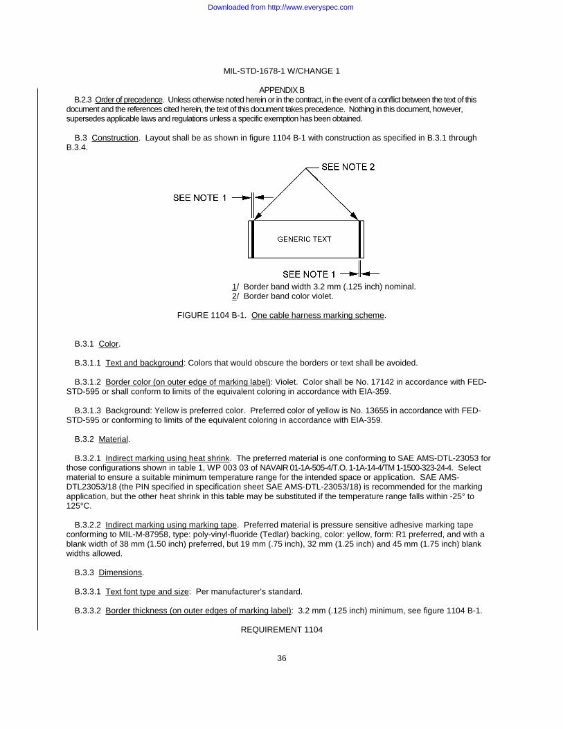
MIL-STD-1678-1 W/CHANGE 1
36
APPENDIX B B.2.3 Order of precedence. Unless otherwise noted herein or in the contract, in the event of a conflict between the text of this document and the references cited herein, the text of this document takes precedence. Nothing in this document, however, supersedes applicable laws and regulations unless a specific exemption has been obtained. B.3 Construction. Layout shall be as shown in figure 1104 B-1 with construction as specified in B.3.1 through B.3.4.
1/ Border band width 3.2 mm (.125 inch) nominal. 2/ Border band color violet.
FIGURE 1104 B-1. One cable harness marking scheme.
B.3.1 Color. B.3.1.1 Text and background: Colors that would obscure the borders or text shall be avoided. B.3.1.2 Border color (on outer edge of marking label): Violet. Color shall be No. 17142 in accordance with FED-STD-595 or shall conform to limits of the equivalent coloring in accordance with EIA-359. B.3.1.3 Background: Yellow is preferred color. Preferred color of yellow is No. 13655 in accordance with FED-STD-595 or conforming to limits of the equivalent coloring in accordance with EIA-359. B.3.2 Material. B.3.2.1 Indirect marking using heat shrink. The preferred material is one conforming to SAE AMS-DTL-23053 for those configurations shown in table 1, WP 003 03 of NAVAIR 01-1A-505-4/T.O. 1-1A-14-4/TM 1-1500-323-24-4. Select material to ensure a suitable minimum temperature range for the intended space or application. SAE AMS-DTL23053/18 (the PIN specified in specification sheet SAE AMS-DTL-23053/18) is recommended for the marking application, but the other heat shrink in this table may be substituted if the temperature range falls within -25° to 125°C. B.3.2.2 Indirect marking using marking tape. Preferred material is pressure sensitive adhesive marking tape conforming to MIL-M-87958, type: poly-vinyl-fluoride (Tedlar) backing, color: yellow, form: R1 preferred, and with a blank width of 38 mm (1.50 inch) preferred, but 19 mm (.75 inch), 32 mm (1.25 inch) and 45 mm (1.75 inch) blank widths allowed. B.3.3 Dimensions. B.3.3.1 Text font type and size: Per manufacturer’s standard. B.3.3.2 Border thickness (on outer edges of marking label): 3.2 mm (.125 inch) minimum, see figure 1104 B-1.
REQUIREMENT 1104
Downloaded from http://www.everyspec.com
MIL-STD-1678-1 W/CHANGE 1
37
B.3.3.3 Border location: Offset at equal distances from outer edges, see figure 1104 B-1. B.3.3.4 Border configuration: Continuous band (violet radial stripe) around label within 3.2 mm (.125 inch) thickness. B.3.3.5 Label dimensions: Size designators for SAE AMS-DTL-23053/18 class 3 and 23053/5 class 3 found in table 2 are the ones that should be used. B.3.4 Printing of border: (Violet band, see figure 1104 B-1). B.3.4.1 Insertion. Border shall be printed using the manufacturer’s standard marking scheme. B.3.4.2 Allowance for flat printed labels. When the printer has the capability to include a violet stripe as part of the marking, and when the printer is setup or designed for flat printed labels, an allowance is given for a break at the two edges of the flat marker (versus requiring a continuous radial violet stripe).
REQUIREMENT 1104
Downloaded from http://www.everyspec.com
MIL-STD-1678-1 W/CHANGE 1
38
REQUIREMENT 1105
FIBER OPTIC CABLING INTERFACE ON EQUIPMENT MODULES
1. Purpose. This requirement establishes fiber optic cabling interface criteria on equipment modules (i.e., electronic module/package) such as a WRA, LRM or LRU). This requirement is intended for developmental, prototype, production, rework and modification programs on military platform fiber optic cable assemblies. 2. Applicable documents. 2.1 General. The documents listed in this section are specified in sections 3, 4, and 5 of this standard practice. This section does not include documents cited in other sections of this standard practice or recommended for additional information or as examples. While every effort has been made to ensure the completeness of this list, document users are cautioned that they must meet all specified requirements of documents cited in sections 3, 4, and 5 of this standard practice, whether or not they are listed. 2.2.1 Specifications, standards, and handbooks. The following specifications, standards, and handbooks form a part of this document to the extent specified herein. Unless otherwise specified, the issues of these documents are those cited in the solicitation or contract. COMMERCIAL ITEM DESCRIPTIONS A-A-59569 - Braid, Wire (Copper, Tin-Coated, Silver-Coated, or Nickel Coated, Tubular or Flat). DEPARTMENT OF DEFENSE SPECIFICATIONS MIL-DTL-38999 - Connectors, Electrical Circular, Miniature, High Density, Quick Disconnect (Bayonet, Threaded and Breech Coupling), Environment Resistant, Removable Crimp and Hermetic Solder Contacts, General Specification For. (Copies of these documents are available online at https://assist.daps.dla.mil/quicksearch/ or from the Standardization Document Order Desk, 700 Robbins Avenue, Building 4D, Philadelphia, PA 19111-5094.) 2.2.2 Non-Government publications. The following documents form a part of this document to the extent specified herein. Unless otherwise specified, the issues of these documents are cited in the solicitation or contract. AEROSPACE INDUSTRIES ASSOCIATION OF AMERICA INC. NAS813 - Cap - Protective, Electrical Connector. NAS820 - Plug - Protective, Electrical Connector. (Copies of these documents can be obtained online at http://www.aia-aerospace.org/ or from Aerospace Industries Association Of America Inc., 1000 Wilson Blvd, Suite 1700, Arlington, VA 22209.) SOCIETY OF AMERICAN ENGINEERS INTERNATIONAL (SAE INTERNATIONAL)
SAE AS5658 - Platform/Subsystem Common Interface Control Document Format. SAE AS85049/138 - Connector Accessories, Electrical, Cap, Dust, Plastic, Category 9.
(Copies of these documents can be obtained online at http://www.sae.org or from SAE International World Headquarters, 400 Commonwealth Drive, Warrendale, PA 15096-0001.)
REQUIREMENT 1105
Downloaded from http://www.everyspec.com
MIL-STD-1678-1 W/CHANGE 1
39
2.3 Order of precedence. Unless otherwise noted herein or in the contract, in the event of a conflict between the text of this document and the references cited herein, the text of this document takes precedence. Nothing in this document, however, supersedes applicable laws and regulations unless a specific exemption has been obtained. 3. Definitions. 3.1 Bend Diameter, Minimum, Short-Term. The short-term bend diameter applies during handling and installing. The short-term bend diameter may be different for simplex tight buffer cable, for simplex loose tube cable, and for convoluted tube or conduit. 3.2 Bend Diameter, Minimum, Long-Term. The long-term bend diameter applies to the completed installation. The long-term bend diameter may be different for simplex, tight buffer cable, for simplex, loose tube cable and for convoluted tube or conduit. 3.3 Cable, loose tube. A fiber optic cable design is one configured with one or more optical fibers are fitted loosely within a tube, giving the optical fibers freedom to move. This mobility and isolation from the tube minimizes the effects of external forces on the performance of the link. The isolation allows cable expansion and contraction with temperature independent of the optical fibers. 3.4 Cable, tight buffer. A fiber optic cable design is one configured with an additional protective coding (additional buffer layer) is applied directly over a coated (buffered) fiber. Buffer material helps preserve the fiber’s inherent strength and provides increased mechanical protection. A tight buffer cable allows cable placement in tighter bends, more roughed handling (such as better crush and impact resistance). 3.5 Chafing. Repeated motions between cabling components, between cabling and equipment between cabling and the structure that result in wear causing mechanical failure and/or degraded or complete loss of the optical signal. Wear is the result of rubbing, excessive twisting and/or bending. Also, chafing may be defined in terms poor installation practices. Chafing includes poor clamping, poor lacing and poor routing. Cabling must be routed, clamped and laced to prevent any contact with equipment or structures. 3.6 Fiber optic cabling. Fiber optic cabling is a term used to include single fiber cable, multiple fiber cable, fiber optic cable bundles and fiber optic cable harnesses. The (optical) fiber is the optical conduit or waveguide transmission media, whereas metallic conductor (wire) is used in an electrical cable. Cable structure is added to make the fibers easier to handle and maintain. The fiber is a thin piece of glass (with a diameter usually around 125 micrometers) that contains and transports the light signals. 3.7 Wire. “A usually pliable metallic strand or rod made in many lengths and diameters, sometimes clad and often electrically insulated, used chiefly for structural support or to conduct electricity.” Source: American Heritage Dictionary, College Edition. 4. Electronic module interface, general requirements. 4.1 Electronic module interface format. Platform or subsystem logical, physical, and environmental interface shall conform to the platform/subsystem interface control documents (ICDs). SAE AS5658 shall be used as the means to standardize and to provide a common document format for the development and comparison of platform/subsystem interface control documents (ICDs). 4.2 Labeling. 4.2.1 WRA label. The triangular shaped label, as specified in 4.1 of Requirement 1104, shall be placed on the electronics module exterior to identify a fiber optic connection port or connector. 4.2.2 Laser classification label. For electronic modules with a laser diode as the transmitting optical source and if feasible as room permits, a label with the laser classification shall be affixed to the exterior. 4.3 BIT. The function of the Built-In-Test (BIT) capability shall be tested, as specified in Requirement 1201, to verify ability for distinguishing in which of three zones (transmitter, cabling, receiver) a fault has occurred.
REQUIREMENT 1105
Downloaded from http://www.everyspec.com
MIL-STD-1678-1 W/CHANGE 1
40
4.4 Optical measurement inspection. Optical source power and optical sensitivity of the receiver shall be obtained for the completed electronics module. Optical power measurement of the transmitting optical source shall be using the method specified in Requirement 1301. Optical sensitivity of the receiver shall be determined by use of an optical source and optical attenuator. Optical source power shall be greater than and optical sensitivity shall be less than the limits specified for those used in the loss budget calculations performed as specified in Requirement 1202. 4.5 End face geometry inspection. Ferrule end face geometry for single ferrule connectors and termini for multiple termini connectors shall be inspected and conform to Requirement 1302. 5. Fiber optic cabling interface requirements 5.1 Cabling. 5.1.1 Externally induced loadings. Internal cabling shall be routed to prevent axial, lateral and torsion loads from being applied. 5.1.2 Access panel removal. Fiber optic cabling route shall be located so that interior optical fiber cables will not be disturbed by disassembly or removal of access panels. 5.1.3 Cable slack. Sufficient cable slack shall be provided to perform required termini reseating and repining at the connector interface, to allow full extension of any vibration isolators or shock mounts, and prevent cable strain at points of bending and clamping. 5.1.4 Anti-chafing measures. Measures shall be taken to prevent chafing due to repeated motions (rubbing, excessive twisting or bending) between cabling components, between cabling and other interior components (including at edges), between cabling and the structure (including at edges) that result in wear causing mechanical failure and/or degraded or complete loss of the optical signal. Measures taken to prevent chafing shall include proper routing, clamping as defined in 3.5 and may include the measures specified in 5.1.4.1 through 5.1.4.3. 5.1.4.1 Use of convoluted tubing. When interior cabling is placed in tubing, among the types of tubing considered for use should be convoluted tubing, as those conforming to Requirement 1101. 5.1.4.2 Supports for routed cable. When interior cabling is secured, among the means considered to prevent chafing by supporting the cabling are metal cushion clamps and lacing tape, as those conforming to Requirement 1101. 5.1.4.3 Routing through cutouts. When interior cabling is routed through cutouts, among the means considered to prevent chafing are metal cushion clamps and grommets, as those conforming to Requirement 1101. 5.1.5 Minimum bend diameter, long term. Minimum long term bend diameter shall not be exceeded for any fiber optic cabling route. 5.1.5.1 Cabling. Unless otherwise specified for the particular cabling used, minimum bend diameter shall not exceed 16 times the cable diameter (i.e., 8 times the cable diameter if working in terms of cable bend radius). For loose tube cabling, the requirement specified for tubing shall be used in lieu of cabling. 5.1.5.2 Tubing. Unless otherwise specified for the particular tubing used, minimum bend diameter shall not exceed 20 times the tubing diameter (e.g., 13 mm (.5 inch) convoluted tubing diameter results in a 254 mm (10 inch) cable bend diameter). 5.2 Connectors. 5.2.1 Segregate fiber optic from electrical connectors. Fiber optic termini shall not be mixed with electrical contacts within the same multiple termini connector. 5.2.1.1 Exception to connector segregation. Connectors external to the platform, such as at the pylons on an aircraft, where only one connection is possible, may accept hybrid cabling (i.e., with a connection containing both fiber optic termini and electrical contacts). Where an exception is approved and fiber optic termini are mixed with electrical contacts, the connector shall be categorized as and marked as a fiber optic connector.
REQUIREMENT 1105
Downloaded from http://www.everyspec.com
MIL-STD-1678-1 W/CHANGE 1
41
5.2.1.2 Segregation of connectors with different fiber types. Unless otherwise specified, no mixed fiber cabling shall be used (i.e, cabling that contain more than one size and/or type of optical fiber) either internal to the equipment module or at least to each fiber optic connector. 5.2.2 Position. Design of electronics module shall consider connector position so as to minimize the number of times each fiber optic connector mated pair is mated and de-mated. Preference for placement is such that a fiber optic connector is the last to de-mate and the first to mate. 5.2.2.1 Minimum spacing for circular connector mating operations. A minimum clearance of 25 mm (1 inch) around 270 degrees of the diameter shall be provided around the connector plug coupling nut (i.e, coupling nut that mates the connector plug to the connector receptacle). Where this requirement cannot be met, connector plug attachment and removal using only common hand technique shall be demonstrated and successfully performed. Where this requirement cannot be met (and removal must be demonstrated and successfully performed), the fiber optic connector shall be placed so that it is the last one off and the first one on. 5.2.2.2 Standardize keyway positioning. Connector installed with the longitudinal axis (i.e., axis parallel to the cabling length) in a horizontal direction shall have the master keyway positioned at the top. Connector installed with the longitudinal axis (i.e., axis parallel to the cabling length) in a vertical direction shall have the master keyway positioned facing the front of the platform. 5.2.2.3 Positioning for drainage. Positioning shall be done so that, when unmated, any condensate or fluids does not drain into but drains out of the connector receptacle. Connectors shall not be positioned or mounted either in standing water or at a site to gather standing water. 5.2.2.4 Redundancy. For essential equipment in which there are separate operating conditions, such as normal and emergency, separate connector shall be used for each of these two conditions where feasible. 5.2.3 Use of preservatives on fiber optic connectors. Preservatives (including corrosion prevention compounds (CPC) and lubricants) shall not be placed on fiber optic connectors. 5.2.4 Selection. Selection of multiple termini connectors shall conform to those specified in Requirement 1102. 5.2.4.1 Applicability. Fiber optic connectors shall be used at locations required to affix internal cabling to the equipment module, join different segments of cabling within the equipment module, and where disconnection is required for maintenance and inspection actions within the equipment module. 5.2.4.2 Separate measures to prevent cross mating. Fiber optic connectors used to provide separation of circular, multiple termini connectors with fiber optic cabling in the same location shall be installed so that it will be impossible to mate the wrong connector in another mating unit. When more than one connector is used at the same location, connector selection shall be implemented in the order listed in 5.2.4.2.1 through 5.2.4.2.3. This ordering is done to limit/standardize on connector configurations that must be supported logistically. Coding of the identical configured connectors (such as color coding) versus positive prevention measures for improper mating shall not be used. 5.2.4.2.1 Shell size. Use alternative shell sizes (to accommodate differences in number of cables in each cable harness). 5.2.4.2.2 Insert cavity arrangement. Use alternative insert with different cavity arrangement (i.e., number of cavities) where alternative insert arrangements are available for a specified shell size. 5.2.4.2.3 Keying positions. Use alternative keying positions. 5.2.5 Insert. 5.2.5.1 Insert configuration. The connector receptacle for multiple termini connectors shall contain the inserts for socket termini. When the multiple termini connector has the insert for the pin terminus configuration only, then retention of the alignment sleeves shall be done in the connector receptacle. Connectors with only fiber optic pin termini, whose mating connector have the alignment sleeves built-in, must use special contacts with a shorter pin to preclude damage to the mating termini.
REQUIREMENT 1105
Downloaded from http://www.everyspec.com
MIL-STD-1678-1 W/CHANGE 1
42
5.2.5.2 Fully populated inserts. Empty cavities in the connector insert shall be filled with dummy (fiber optic) termini. For a MIL-DTL-38999 series III connector, sealing plugs (at the rear grommet) alone may be used in lieu of dummy termini (with sealing plugs) in empty cavities. 5.2.6 Sealing. Sealing material (such as gaskets and o-rings) shall be used on the connector receptacle flange when sealing is required on the mounting surface. For flange mounting connector receptacles, fasteners shall be placed in and secured in all holes of the mounting flange. 5.2.6.1 EMI protection. If the system interfacing with the fiber optic cabling requires EMI protection, EMI shielding for the internal fiber optic cabling can be addressed with an approved conductive gasket/grommet and/or with metal braid sleeve in accordance with A-A-59569, as applicable. Also, if required, an approved conductive gasket or o-ring shall be used at the flange of the connector receptacle mounted on the exterior of the equipment module. 5.3 Dust cover requirements for multiple termini connectors. Measures shall be taken to protect the connector interior and termini of unmated connectors from contamination (such as dust and fluids). 5.3.1 Supply as part of connector. Dust covers shall be provided with and affixed to each fiber optic connector receptacle on the equipment module. 5.3.2 Dust cover attachment. Dust cover shall consist of a metal cap with lanyard (or composite cap with lanyard, as applicable). The lanyard shall be the means used to affix the dust cover to the connector. 5.3.3 Dust protection during production. Through production (except when uncovered for assembly operation) unmated fiber optic connectors on the equipment module shall be suitably covered. Plastic dust caps such as those conforming to AS85049/138, NAS813 and NAS820 may be used for this purpose. 5.4 Dummy stowage receptacles. 5.4.1 Installation instructions. Installation instructions provided with the equipment module shall specify that a dummy stowage receptacle, with dust cover and lanyard, be provided for each connector receptacle on the equipment module. Installation instructions shall list the PIN (military specification Part Identification Number) for each dummy stowage receptacle and dust cover required. 5.4.2 Location. The dummy stowage receptacle is to be located adjacent to the equipment module. 5.4.3 Intent. Dummy stowage receptacles are used to secure connector plugs when unmated from the equipment module. 6. Notes. 6.1 Lessons learned. 6.1.1 Label fiber optic capable equipment (i.e., Electronics Module/Package) identification. Use common labeling to identify fiber optic connector ports on equipment, such as a WRA, for compliance with both this labeling and laser safety requirements. This ensures that when a connector on a fiber capable box is opened, the proper cleaning process is enforced. 6.2 Intended use. On these platforms, equipment (electronic module/package) such as a WRA, LRM or LRU with internal fiber optics.
REQUIREMENT 1105
Downloaded from http://www.everyspec.com

MIL-STD-1678-1 W/CHANGE 1
43
CABLING SUPPORT REQUIREMENTS
(1201-1202)
Downloaded from http://www.everyspec.com
MIL-STD-1678-1 W/CHANGE 1
44
REQUIREMENT 1201
BUILT-IN TEST (BIT)
1. Purpose. The function of BIT in a fiber optic system is to determine if there is acceptable optical transmission through the system. The fiber optic system consists of the transmitter, intermediate fiber optic cabling (including connector and splicing components) and receiver. For purposes of troubleshooting, these are considered as three ambiguity zones. The intent of BIT is to reduce the ambiguity zones. This requirement is intended for developmental, prototype, production, rework, and modification programs on military platform fiber optic systems. 2. Applicable documents. 2.1 General. The documents listed in this section are specified in sections 3, 4, and 5 of this standard practice. This section does not include documents cited in other sections of this standard practice or recommended for additional information or as examples. While every effort has been made to ensure the completeness of this list, document users are cautioned that they must meet all specified requirements of documents cited in sections 3, 4, and 5 of this standard practice, whether or not they are listed. 2.2 Government documents. 2.2.1 Specifications, standards, and handbooks. The following specifications, standards, and handbooks form a part of this document to the extent specified herein. Unless otherwise specified, the issues of these documents are those cited in the solicitation or contract. DEPARTMENT OF DEFENSE HANDBOOKS MIL-HDBK-217 - Reliability Prediction of Electronic Equipment (Copies of this document are available online at https://assist.daps.dla.mil/quicksearch/ or from the Standardization Document Order Desk, 700 Robbins Avenue, Building 4D, Philadelphia, PA 19111-5094.) 2.3 Order of precedence. Unless otherwise noted herein or in the contract, in the event of a conflict between the text of this document and the references cited herein, the text of this document takes precedence. Nothing in this document, however, supersedes applicable laws and regulations unless a specific exemption has been obtained. 3. Definitions. 3.1 Ambiguity zones. Categorizing different classes of components that comprise a fiber optic communications network into more than one segment (or zone) with the inability to distinguish a faulty component within those zones (the ambiguity). A simple three zone system may consist of the transmitter, cabling, and receiver. The ambiguity is the inability to distinguish in which zone the fault occurs. The intent of BIT is to reduce the ambiguity zones to one. 3.2 Background (or continuous or periodic) BIT. Monitoring routine that runs continuously on a non-interference basis during normal operation of the system/equipment and detects and displays “No-Go’s” or degraded functions to the crew providing 100 percent detection of functional and critical failures. 3.3 Initiated (or polled) BIT. Routine for a status or system check that is performed by the pilot, crew or maintainer at a time of the initiator’s choosing. Initiated BIT provides more in-depth information than Start-up BIT or Background BIT. Constraints such as duration or interference with other operations being performed may negate the ability to perform some of the checks in the background or during start-up. (One example is avoidance of a check on flight control surfaces that would require movement during flight.) Level or type of checks performed can be varied for different users. For example, an initiated BIT may consist of checking system availability for pilots and checking items to remove and replace for maintainers. 3.4 Mean Time Between Critical Failure (MTBCF). This metric is a measure of the systems reliability which includes the effects of any fault tolerance which may exist. The average time between failures which causes a loss of a system function defined as “critical” by the customer.
REQUIREMENT 1201
Downloaded from http://www.everyspec.com
MIL-STD-1678-1 W/CHANGE 1
45
3.5 Mean Time Between Failure (MTBF). This metric is a basic measure of reliability for repairable items. It is the average time during which all parts of the item perform within their specified limits, during a particular measurement period under stated conditions. 3.6 Mean Time Between Maintenance (MTBM). This metric is a basic measure of reliability for repairable fielded systems. It is the average time between all system maintenance actions. Maintenance actions may be for unscheduled repair or scheduled preventative purposes. 3.7 Start-up (or power-up) BIT. Monitoring routine initiated on power-up of the system/equipment. This routine may be identical to background BIT or may be unique depending on specific needs of the system/equipment. NOTE: One can use MTBM and MTBF interchangeably as long as you know the definitions. Scheduled and
preventative maintenance are factored into the MTBM value. Scheduled and preventative maintenance are not factored into the MTBF value.
4. General requirements. 4.1 Performance. BIT software shall enable both automatic and polled checks of the fiber optic cabling system during ground operations and in-flight. If an unacceptable level of optical transmission is found, BIT shall include features to (1) interrogate the fiber optic cabling system, (2) identify the fault/break, and (3) store the fault/break data in terms of location from transmitter. 4.1.1 Checks with cabling connected. BIT checks shall be implemented without disconnecting mated connector pairs. 4.1.2 Duration for start-up BIT. Start-up BIT shall be implemented in 1 minute or less once the system being monitored is on-line. 4.1.3 System operation allowance during background BIT. Background (also referred to as continuous or periodic) BIT shall be non-intrusive to the actual data transmission. 4.1.4 Off-line use of BIT. Initiated BIT shall have the capability of being performed off-line (when a platform is in maintenance and not an operational mode) for applications such as when a fault is detected. 4.1.5 Impact on system reliability. The BIT methodology employed shall not degrade the fiber optic system reliability. 4.2 BIT parameters. Fault recognition shall narrow fault location to within 10 cm (3.94 inches). Fault data generated shall be in form of an ASCII tab delimited file with look-up table in terms of fault isolation (location of fault/break; such as at transmitter, receiver, or cabling), loss in dB and distance from transceiver.
NOTE: Intent is to define a standardized means to extract and interpret the data so that a laptop PC, or a universal aircraft recorder (UAR), can be used. Consideration will be given for other options and your alternative for a more user friendly option is welcome and encouraged. Submit alternatives by e-mail through the NSWC DD Warfare Systems Department at [email protected].
4.3 Compatibility with legacy transceivers. BIT capable transceivers shall be interchangeable with existing legacy transceivers.
REQUIREMENT 1201
Downloaded from http://www.everyspec.com
MIL-STD-1678-1 W/CHANGE 1
46
4.4 Verification methods. Adequacy of BIT provided shall be evaluated by the three parameters of detection rate, isolation rate, and false alarm rate. Detection rate is the percent of failures found by BIT divided by the total number of failures (including non-electronic failures) of these systems. The minimum acceptable detection rate shall be 90 percent. Isolation rate for the transmitter and receiver is the percent of occurrences that the faulty transmitter or receiver is correctly identified from two or more transmitters or receivers in the cabling system divided by the total number of occurrences. Isolation rate for the intermediate cabling shall be the percentage of occurrences that are correctly isolated to the location of the fault/break divided by the total number of occurrences. The minimum acceptable isolation rate shall be 95 percent. False Alarm rate is the percent of false alarms when the cabling system remains working divided by the total number of BIT detections. Alternatively, the false alarm rate may be measured as the mean time between false alarms or as the mean flight hours between false alarms. The maximum acceptable false alarm rate shall be 5 percent. 5. Reliability requirements. 5.1 Design. The reliability of the basic design shall be determined by use of the Reliability Block Diagram Model or Reliability Prediction Report where the reliability of individual components, circuits/circuit cards (such as a line replaceable unit), replaceable electronics, or aviation boxes (such as line replaceable modules and weapons replaceable assemblies) are calculated in terms of mission time. 5.2 Use of MIL-HDBK-217: "Reliability Prediction of Electronic Equipment". MIL-HDBK-217, or a software package that uses MIL-HDBK-217 as the model for the calculations, shall be used as the means to conduct the predicted reliability of a design (under ideal conditions) based simply on the number of components and their individual failure rates. 5.3 Factors and variables used in reliability calculation. MIL-HDBK-217 shall be augmented with contemporary values (such as the multiplication factors referred to in MIL-HDBK-217 as Pi factors) of fiber optic components. Failure rate contributions may be used for some degradation variables or components in lieu of multiplication factors. Basis for degradation variables can be on overall legacy performance data and Highly Accelerated Life Testing (HALT) data versus restricted to a specific cable configuration or specific manufacturer. 5.4 Acceptable ways to improve reliability. Measures to be considered shall include redundancy, use of better quality parts, increasing of design margins (de-rating of performance expectations based on mission performance). Actions considered shall include increased preventative maintenance and routine inspections/sampling of statistically significant sample sizes. Testing performed includes Highly Accelerated Life/Stress Testing (HALT/HAST), Environmental Stress Screening (ESS), Reliability Development/Growth Testing (RDGT), or Highly Accelerated Stress Screening (HASS). 5.5 Acceptance criteria. Acceptance criteria are platform specific. Acceptable MTBF will be different depending on the mission duration, expected environment, expected life of the system, safety considerations, mission criticality, cost and other factors. As an example, the predicted reliability numbers for systems in a patrol aircraft are very different from the same systems in a fighter aircraft. 6. Notes. 6.1 Lessons learned. 6.1.1 Utilize BIT to reduce ambiguity zones. BIT is required to break the ambiguity zones from three to one. This allows maintainers to determine which is failing, the transmitting box, receiving box, or cable plant, and affect the appropriate repair.
REQUIREMENT 1201
Downloaded from http://www.everyspec.com
MIL-STD-1678-1 W/CHANGE 1
47
REQUIREMENT 1202
LOSS BUDGET CALCULATION
1. Purpose. This requirement establishes criteria for calculating the loss budget to ensure the fiber optic light transmission path (in a fiber optic system) operates within the minimum required optical performance specification over the expected life of the system (the loss budget margin > 0 at end of life). This requirement is intended for developmental, prototype, production, rework, and modification programs on military platform fiber optic cable assemblies. 2. Applicable documents. 2.1 General. The documents listed in this section are specified in sections 3, 4, and 5 of this specification. This section does not include documents cited in other sections of this specification or recommended for additional information or as examples. While every effort has been made to ensure the completeness of this list, document users are cautioned that they must meet all specified requirements of documents cited in sections 3, 4, and 5 of this specification, whether or not they are listed. 2.2 Government documents. 2.2.1 Specifications, standards, and handbooks. The following specifications, standards, and handbooks form a part of this document to the extent specified herein. Unless otherwise specified, the issues of these documents are those cited in the solicitation or contract. DEPARTMENT OF DEFENSE STANDARDS MIL-STD-2052 - Fiber Optic System Design. (Copies of these documents are available online at https://assist.daps.dla.mil/quicksearch/ or from the Standardization Document Order Desk, 700 Robbins Avenue, Building 4D, Philadelphia, PA 19111-5094.) 2.3 Non-Government publications. The following documents form a part of this document to the extent specified herein. Unless otherwise specified, the issues of these documents are cited in the solicitation or contract. SOCIETY OF AUTOMOTIVE ENGINEERS (SAE International) SAE AS-5603 - Digital Fiber Optic Link Loss Budget Methodology for Aerospace Platforms. SAE AS-5750 - Loss Budget Specification for Fiber Optic Links. (Copies are available from http://www.sae.org or to SAE International, 400 Commonwealth Drive, Warrendale, PA 15036-0001.) 2.4 Order of precedence. Unless otherwise noted herein or in the contract, in the event of a conflict between the text of this document and the references cited herein, the text of this document takes precedence. Nothing in this document, however, supersedes applicable laws and regulations unless a specific exemption has been obtained. 3. Definitions. 3.1 Optical loss. The calculated loss in optical power between a known, measured amount of power (through one or two MQJs) compared to the measured optical power through a cable assembly (link, harness, or others under test). 3.2 End-to-end cable assembly (fiber optic). The path light travels from the transmitter to the receiver. This path includes the connections up to the transmitting device, connections up to the receiving device and one or more sections of fiber optic cable.
REQUIREMENT 1202
Downloaded from http://www.everyspec.com
MIL-STD-1678-1 W/CHANGE 1
48
3.3 Loss budget. The loss budget is the allocation of optical losses within a fiber optic cable assembly. These losses include component losses (cables, connectors, and others), optical power penalties, and other performance degradations (such as environmental losses), and an optical margin for unforeseen or unpredictable changes within the communications transmission path. 3.4 Environmental margin. The environmental margin is a built in margin to allow for changes in the fiber optic cable plant due to environmental effects. 3.5 Unallocated margin (design margin). The unallocated margin is a built in margin to allow for unforeseen changes in the fiber optic cable plant, including aging of the passive components. Unallocated margin provides design margin when design assumptions are violated during the lifetime of the cable assembly. 4. General criteria. Each end-to-end cable assembly shall include the calculation of a loss budget as part of the system design. 4.1 Acceptable models to calculate loss budget. The loss budget shall be calculated using the worst case method. When the statistical model is calculated, then a worst case model shall be calculated and used as the basis of comparison. 4.1.1 Aircraft platforms. Methods and parameters used in the loss budget calculation shall conform to SAE AS5750. When specified or when sufficient data exists to allow end of life calculations, statistical or numerical (simulation) method may be cited. End of life calculations shall be performed using parameters specified in category B of SAE AS-5750. 4.2 Parameters to be included in loss budget calculations. 4.2.1 Models. Three different models of loss budgets using the worst case model may be used; however, the model used for comparison shall be the worst case loss budget as specified in 4.2.1a. The other three types in 4.2.1b through 4.2.1d may be prepared along with the model in accordance with 4.2.1a. a. Worst case (3 dB environmental margin). This loss budget is an analysis that uses a worst case value for the components
and assumes a worst case value of 3 dB for environmental effects. b. Worst case (calculated environmental margin). This loss budget is an analysis that uses a worst case value for
components and assumes a statistical value for environmental effects. c. Worst case (no environmental margin). This loss budget assumes that there is no optical loss due to
environmental factors. A worst case value is used for the components. If this loss budget is used, then there is no leeway to go beyond the determined loss budget. When an environmental margin is included in the loss budget, the margin provides a buffer to absorb any environmentally induced losses in the fiber optic cable plant.
d. Statistical. This loss budget is an analysis that uses statistical values for both the component losses and for the
environmental effects. 4.2.2 Unallocated margin. An unallocated margin shall be included in the loss budget. The unallocated margin is a built in margin to allow for unforeseen changes in the fiber optic cable plant, including aging of the passive components. Unallocated margin also provides an indication of how much optical signal can degrade if cable plant components get abused. Loss budget calculations assume a 3 dB unallocated margin. Unallocated parameters shall include: a. Connector and cable aging. b. Connector multiple mating and de-mating. c. Cable spooling operations.
REQUIREMENT 1202
Downloaded from http://www.everyspec.com
MIL-STD-1678-1 W/CHANGE 1
49
d. Connections added after cable plant is installed. e. Poor quality fiber (larger optical loss). f. Cable plant damage.
4.2.3 Environmental margin. An environmental margin shall be included in the loss budget. Environmental effects include temperature, humidity, vibration, mechanical shock, and cable in static tension and compression. Three different types of environmental margins are described below; however, only one of the first two type shall be used. a. 3 dB margin. This margin assumes a worst case value of 3 dB for environmental effects. b. Calculated margin. This margin uses a statistical value for each component. A mean environmental optical loss is applied
along with a specified standard deviation. The statistical margin calculates what would be expected on a representative basis. There is less than a one percent probability that the actual cable plant, environmental optical loss will be worse.
c. No environmental margin. This margin assumes that there is no optical loss due to environmental factors. If this value is
used, then there is no leeway to go beyond the determined optical power budget. 4.3 Methods. 4.3.1 General. The optical loss shall be measured using the method specified in SAE AS-5603 and tailored as required. If applicable and as an alternative, the loss budget may be calculated using the method specified in MIL-STD-2052. 4.3.2 Aircraft platforms. The loss budget shall be calculated using the method specified in SAE AS-5603. 4.4 Beginning of life. Loss budget shall be calculated using only the worst case model when limited information exists on the characteristics of the components in the system being built. As more experience and data is obtained with the components and more insight with the statistical distribution is achieved, then and only then, shall a statistical model be acceptable. 4.4.1 Unallocated margin. In the early stages of the design process, a 3 dB unallocated margin shall be used. The value shall be used to account for the higher uncertainty in the component distribution and performance in addition to those parameters specified in 4.2.2. 4.5 Mission safety critical systems. As part of the system design process, the loss budget shall be calculated with a 3 dB unallocated margin for mission safety critical systems. 5. Implementation. This requirement directs all platforms utilizing fiber optics to measure the optical loss in each cable assembly (optical loss of each link), to measure the end-to-end optical loss and to implement them in a timely and cost-effective manner. This includes obtaining cost estimates associated with the implementation on existing contracts. 6. Notes. 6.1 Lessons learned. 6.1.1 Calculation models. The only two models to calculate the loss budget shall be the statistical model with 3σ or greater statistics and the worst case model with a 3 dB environmental margin. Typically this “worst case approach” is a bit more conservative than the “statistical approach. The “worst case approach” gives the fiber optic system designer a higher “confidence” that a given cable assembly will work NO MATTER WHAT when compared to the “statistical model”. The “statistical model” allows the fiber optic system designer to specify the degree of “confidence” inherent in the system design (3σ statistics gives a 0.999 confidence level). If good statistical data is not available for all components, “In-between” statistical and worst case approaches are also valid.
REQUIREMENT 1202
Downloaded from http://www.everyspec.com
MIL-STD-1678-1 W/CHANGE 1
50
6.1.2 Design (unallocated) margin. Design margin must be included in mission essential cable assembly loss budgets. A 3 dB design margin is recommended to account for unexpected losses in mission essential cable assemblies. 6.1.3 Other criteria in loss budget. Active and passive component environmental effects must be included in the link budget calculation. Transmitter and receiver aging factors must be included in the loss budget calculation. 6.2 Intended use. 6.2.1 Calculation models. The only two models to calculate the loss budget shall be the statistical model with 3σ or greater statistics and the worst case model with a 3 dB value for each margin in the loss budget (such as design and environmental). Typically this “worst case approach” is a bit more conservative than the “statistical approach. The “worst case approach” gives the fiber optic system designer a higher “confidence” that a given cable assembly will work NO MATTER WHAT when compared to the “statistical model”. The “statistical model” allows the fiber optic system designer to specify the degree of “confidence” inherent in the system design (i.e., 3σ statistics gives a 0.999 confidence level). If good statistical data is not available for all components, “In-between” statistical and worst case approaches are also valid. 6.2.2 Design (unallocated) margin. Design margin must be included in mission essential cable assembly loss budgets. A 3 dB design margin is recommended to account for unexpected losses in mission essential cable assemblies. 6.2.3 Other criteria in loss budget. Active and passive component environmental effects must be included in the link budget calculation. Transmitter and receiver aging factors must be included in the loss budget calculation.
REQUIREMENT 1202
Downloaded from http://www.everyspec.com
MIL-STD-1678-1 W/CHANGE 1
51
CABLING IMPLEMENTATION VERIFICATION REQUIREMENTS
(1301-1304)
Downloaded from http://www.everyspec.com

MIL-STD-1678-1 W/CHANGE 1
52
REQUIREMENT 1301
OPTICAL MEASUREMENTS INSPECTION
1. Purpose. This requirement establishes test criteria for optical measurements in a fiber optic cable assembly. This requirement is intended for developmental, prototype, production, rework, and modification programs on military platform fiber optic cable assemblies. 2. Applicable documents. 2.1 General. The documents listed in this section are specified in sections 3, 4, and 5 of this requirement. This section does not include documents cited in other sections of this standard practice or recommended for additional information or as examples. While every effort has been made to ensure the completeness of this list, document users are cautioned that they must meet all specified requirements of documents cited in sections 3, 4, and 5 of this standard practice, whether or not they are listed. 2.2 Government documents. 2.2.1 Specifications, standards, and handbooks. The following specifications, standards, and handbooks form a part of this document to the extent specified herein. Unless otherwise specified, the issues of these documents are those cited in the solicitation or contract. DEPARTMENT OF DEFENSE STANDARDS MIL-STD-2042 - Fiber Optic Cable Topology Installation, Standard Methods for Naval Ships, Part 6. (Copies of these documents are available online at https://assist.daps.dla.mil/quicksearch/ or from the Standardization Document Order Desk, 700 Robbins Avenue, Building 4D, Philadelphia, PA 19111-5094.) 2.3 Other Government documents, drawings, and publications. The following other Government documents, drawings, and publications form a part of this standard practice to the extent specified herein. Unless otherwise specified, the issues are these documents are those cited in the solicitation or contract. NAVAIR 01-1A-505-4/ - Aircraft Fiber Optic Cabling, Technical Manual, Installation T.O. 1-1A-14-4 and Testing Practices, Work Package 009. (A copy of this document is available online at: https://jswag.navair.navy.mil. At the home page select “Document Library” (on left side), then select the “Committee” folder, then “JFOWG” followed by the “Maintenance Documents” folder. If unable to access this Web Site, request an application by e-mail to NSWC DD Warfare Systems Department at: ([email protected].) 2.4 Order of precedence. Unless otherwise noted herein or in the contract, in the event of a conflict between the text of this document and the references cited herein, the text of this document takes precedence. Nothing in this document, however, supersedes applicable laws and regulations unless a specific exemption has been obtained. 3. Definitions. 3.1 Optical loss. The calculated loss in optical power between a known, measured amount of power (through one or two MQJs) compared to the measured optical power through a cable assembly (link, harness, and others under test). 3.2 End-to-end cable assembly (fiber optic). The path light travels from the transmitter to the receiver. This path includes the connections up to the transmitting device, connections up to the receiving device and one or more sections of fiber optic cable (such as one or more single segment, fiber optic cable harnesses).
REQUIREMENT 1301
Downloaded from http://www.everyspec.com
MIL-STD-1678-1 W/CHANGE 1
53
3.3 Measurement Quality Jumper (MQJ). The MQJ is a low loss jumper that is used with test equipment to perform optical loss measurements. The MQJ must meet stringent optical loss requirements to ensure accuracy of measurements performed. Measurements must be accurate and repeatable. The accuracy and repeatability of your measurement is only as good as your MQJ. As the MQJ degrades with use, so does the measurement accuracy. The MQJ consists of a single fiber cable with a connector at one end that mates to the test equipment and a connector at the other end which mates to the cable assembly segment or segments under test. 3.4 Cable assembly, single segment (fiber optic). Single fiber assemblies consist of cabling with connectors on each end. Different configurations for this cable assembly may be multiple termini connector cable assemblies (such as plug-to-plug or plug-to-receptacle configurations) and multiple termini plug/receptacle-to-single fiber connector assemblies. 3.5 Cable assembly, multiple segment (fiber optic). Two or more single segment cable assemblies mated together at the fiber optic connectors. 3.6 Cable assembly (fiber optic). One segment or an assembly constructed from a fiber optic cable with connectors on each end. 4. General requirements. Inspection for optical measurements shall include those for optical loss and optical return loss. 4.1 Optical loss, general. The optical loss shall be measured using the method specified in Part 6 of MIL-STD-2042 using the optical loss one jumper method. 4.2 Optical loss, aircraft platforms. The optical loss on aircraft platforms shall be measured using the method specified in subordinate work package 009 01 of NAVAIR 01-1A-505-4/T.O. 1-1A-14-4/TM 1-1500-232-24-4 using the optical loss two jumper method. 4.3 Optical return loss. The optical loss shall be measured using the method specified in subordinate work package 009 04 of NAVAIR 01-1A-505-4/T.O. 1-1A-14-4/TM 1-1500-232-24-4. 4.4 Measurement Quality Jumper (MQJ). Acceptable low optical loss of each MQJ used for optical measurements in 4.1 through 4.3 shall be verified using the method specified in subordinate Work Package 009 04 of NAVAIR 01-1A-505-4/T.O. 1-1A-14-4/TM 1-1500-232-24-4. 5. Implementation. This requirement directs all platforms utilizing fiber optics to measure the (1)optical loss in each cable assembly (optical loss of each link), (2) to measure the end-to-end optical loss (once fabricated or installed), and (3) to implement them in a timely and cost-effective manner. This includes obtaining cost estimates associated with the implementation on existing contracts.
REQUIREMENT 1301
Downloaded from http://www.everyspec.com
MIL-STD-1678-1 W/CHANGE 1
54
6. Notes. 6.1 Lessons learned. 6.1.1 Cost factor. Costly not to inspect. It is very costly to have to remove fiber optic cabling or equipment when degraded optical performance occurs. If deficiencies are not found through initial inspection and testing prior to installation versus finding them after installation, they will have to be replaced resulting in maintenance costs. In addition, if the repair equipment is added without following the proper procedures such as confirming that the connectors are clean, they may damage the cable plant hardware resulting in yet more expensive repair on the in situ cable plant. 6.1.2 Not meeting loss in an operating environment. If initial loss (in benign environment at beginning of life) is not within the specified limits, then no guarantee of having the margin to obtain an acceptable loss in an operating environment. Recall that the loss budget calculation includes environmental and mechanical margins (operating environment) based on a value for the initial loss (loss budget = initial + environmental margin + mechanical margin + other margins/factors). 6.2 Intended use. On these platforms, the fiber optic cable assemblies intended to be measured for optical loss include (1) aircraft cable harnesses, (2) other type constructions of a cable assembly, and (3) other miscellaneous cabling.
REQUIREMENT 1301
Downloaded from http://www.everyspec.com
MIL-STD-1678-1 W/CHANGE 1
55
REQUIREMENT 1302
END FACE GEOMETRY INSPECTION
1. Purpose. This requirement establishes criteria for fiber optic terminus and single ferrule connector endface inspection. This requirement is intended for developmental, prototype, production, rework, and modification programs on military platform fiber optic cable assemblies. 2. Applicable documents. 2.1 General. The documents listed in this section are specified in sections 3, 4, and 5 of this requirement. This section does not include documents cited in other sections of this standard practice or recommended for additional information or as examples. While every effort has been made to ensure the completeness of this list, document users are cautioned that they must meet all specified requirements of documents cited in sections 3, 4, and 5 of this standard practice, whether or not they are listed. 2.2 Government documents. 2.3 Other Government documents, drawings, and publications. The following other Government documents, drawings, and publications form a part of this standard practice to the extent specified herein. Unless otherwise specified, the issues are these documents are those cited in the solicitation or contract. NSWCCD-SSES - Method to Measure Ferrule End Faces on Fiber Optic Connectors and ltr 9504 Ser 96315/067 Termini. of 31 October 2003. (Copies of these documents can be obtained at web site: https://jswag.navair.navy.mil. At the home page select “Document Library” (on left side), then select the “JFOWG” folder followed by the “Maintenance Documents” folder.) 2.4 Order of precedence. Unless otherwise noted herein or in the contract, in the event of a conflict between the text of this document and the references cited herein, the text of this document takes precedence. Nothing in this document, however, supersedes applicable laws and regulations unless a specific exemption has been obtained. 3. Definitions. 3.1 End face, domed. A ferrule in which the mating connection surface has a radius (or domed) shape (see figure 1302-1). 3.2 End face, ferrule. Ferrule surface contacting the mating ferrule and the mating fiber. Also, the surface that is perpendicular to the longitudinal axis of the optical fiber. 3.3 End face, flat. Ferrule surface contacting the mating ferrule and which the connection surface has essentially a planar (flat) shape with a very limited degree of tilt. 3.4 End face, geometry. Measurement of the ferrule end face for radius of curvature, measurement of the fiber from a defined surface for fiber height, and measurement of the highest point on the surface contour from the center of the fiber for offset (see figure 1302-1).
REQUIREMENT 1302
Downloaded from http://www.everyspec.com
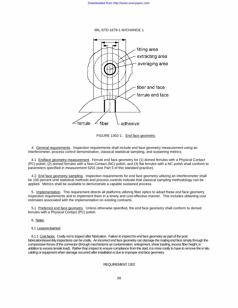
MIL-STD-1678-1 W/CHANGE 1
56
FIGURE 1302-1. End face geometry. 4. General requirements. Inspection requirements shall include end face geometry measurement using an interferometer, process control demonstration, classical statistical sampling, and sustaining metrics. 4.1 Endface geometry measurement. Ferrule end face geometry for (1) domed ferrules with a Physical Contact (PC) polish, (2) domed ferrules with a Non-Contact (NC) polish, and (3) flat ferrules with a NC polish shall conform to parameters specified in measurement 5201 (see Part 5 of this standard practice). 4.2 End face geometry sampling. Inspection requirements for end face geometry utilizing an interferometer shall be 100 percent until statistical methods and process controls indicate that classical sampling methodology can be applied. Metrics shall be available to demonstrate a capable sustained process. 5. Implementation. This requirement directs all platforms utilizing fiber optics to adopt these end face geometry inspection requirements and to implement them in a timely and cost-effective manner. This includes obtaining cost estimates associated with the implementation on existing contracts. 5.1 Preferred end face geometry. Unless otherwise specified, the end face geometry shall conform to domed ferrules with a Physical Contact (PC) polish. 6. Notes. 6.1 Lessons learned. 6.1.1 Cost factor. Costly not to inspect after fabrication. Failure to inspect for end face geometry as part of the post fabrication/assembly inspections can be costly. An incorrect end face geometry can damage the mating end face simply through the compressive forces of the connector (through mechanisms as contamination. entrapment, shear loading, excess fiber height, in addition to excess tensile load). Rather than inspect to ensure compliance from the start, it is more costly to have to remove the in situ cabling or equipment when damage occurred after installation is due to improper end face geometry.
REQUIREMENT 1302
Downloaded from http://www.everyspec.com
MIL-STD-1678-1 W/CHANGE 1
57
6.1.2 Subcontractor inspections. Maintain constant vigilance with vendors constructing both cabling (harnesses) and equipment modules (such as a WRA or LRU). In particular, ensure receipt of connector/termini with end faces that are properly polished and meet end face geometry requirements. Unless constant vigilance is maintained, common practice experienced is for the vendor to default back to improper fabrication. 6.2 Intended use. On these platforms, the fiber optic cable assemblies intended to be inspected include (1) cable harnesses, (2) equipment (electronic module/package) such as a WRA, LRM, or LRU with internal fiber optics, (3) circuit card modules and assemblies with internal fiber optics, (4) fiber optic test jumpers, and (5) other miscellaneous cabling.
REQUIREMENT 1302
Downloaded from http://www.everyspec.com
MIL-STD-1678-1 W/CHANGE 1
58
REQUIREMENT 1303
FIBER OPTIC CABLING POST INSTALLATION INSPECTION
1. Purpose. This requirement establishes criteria for inspection of fiber optic cabling after installation or performance of a maintenance action. This requirement is intended for developmental, prototype, production, rework, and modification programs on military platform fiber optic cable assemblies. 2. Applicable documents. 2.1 General. The documents listed in this section are specified in sections 3, 4, and 5 of this standard practice. This section does not include documents cited in other sections of this standard practice or recommended for additional information or as examples. While every effort has been made to ensure the completeness of this list, document users are cautioned that they must meet all specified requirements of documents cited in sections 3, 4, and 5 of this standard practice, whether or not they are listed. 2.2 Other Government documents, drawings, and publications. The following other Government documents, drawings, and publications form a part of this standard practice to the extent specified herein. Unless otherwise specified, the issues are these documents are those cited in the solicitation or contract. NAVAIR 01-1A-505-1/ - Technical Manual, Installation and Testing Practices, Aircraft Fiber Optic T.O. 1-1A-14/TM Cabling. 1-1500-232-24-4 (A copy of this document is available online at: https://jswag.navair.navy.mil. At the home page select “Document Library” (on left side), then select the “Committee” folder, then “JFOWG” followed by the “Maintenance Documents” folder. If unable to access this Web Site, request an application by e-mail to NSWC DD Warfare Systems Department at: ([email protected].) 2.3 Order of precedence. Unless otherwise noted herein or in the contract, in the event of a conflict between the text of this document and the references cited herein, the text of this document takes precedence. Nothing in this document, however, supersedes applicable laws and regulations unless a specific exemption has been obtained. 3. Definitions. 3.1 Chafing. Repeated motions between cabling components, between cabling and equipment, between cabling and the structure that result in wear causing mechanical failure or degraded or complete loss of the optical signal. Wear is the result of rubbing, excessive twisting, or bending. Also, chafing may be defined in terms of poor installation practices. Chafing includes poor clamping, poor lacing, and poor routing. One determined best practice to implement as a corrective action is “clearance is the best route - get no chafing”. Cabling must be routed, clamped, and laced to prevent contact with equipment or structures. 4. Requirement. 4.1 Inspection method. Inspection of the cabling after installation and performance of a maintenance action shall be performed in accordance with subordinate Work Package WP 014 01 of NAVAIR 01-1A-505-4/T.O. 1-1A-14-4/TM 1-1500-323-24-4. 5. Inspection criteria. 5.1 Determination of proper installation. Inspection shall be performed in accordance with 4.1 to determine post platform installation adequacy. 5.2 Accessibility. Inspection shall be performed to determine cabling accessibility for both inspection and maintenance. 5.3 Inaccessible areas. Inspection shall be performed to determine adequacy of both protective measures and ability to facilitate maintenance in inaccessible areas.
REQUIREMENT 1303
Downloaded from http://www.everyspec.com
MIL-STD-1678-1 W/CHANGE 1
59
5.4 Maintenance. 5.4.1 Inspection. After maintenance, inspection shall be performed in accordance with 4.1 to determine maintenance action adequacy and an emphasis on observing any degree of chafing that may have occurred during installation, maintenance, or operation. 5.4.2 Operation/system integrity. Functional check shall be performed to ensure system operation after completion of 5.4.1. 6. Notes. 6.1 Lessons learned. 6.1.1 Address maintenance issues. Post installation inspection is critical to identify issues and take action to address. Failure to do so can cause the required maintenance to increase. 6.1.2 Share lessons learned. Post installation inspection is an opportunity for the inspector to share lessons learned with the installer or maintainer. This sharing can avoid repeating the same mistakes. 6.1.3 Enforce commonality. Post installation inspection can determine if common (specified) hardware is used and common procedures are followed. Non-specified hardware may fail to function as originally designed. 6.1.4 Evaluate training. Post installation inspection can determine if training of proper installation and maintenance procedure are being taught and are effective, and if so, understood by installing and maintenance personnel. This inspection can verify prevention of regression to “wiring” mentality (“It ain’t wire”). 6.2 Intended use. On these platforms, the fiber optic cable assemblies intended to be inspected include (1) cable harnesses, (2) equipment (electronic module/package) such as a WRA, LRM or LRU with internal fiber optics, (3) circuit card modules and assemblies with internal fiber optics, (4) fiber optic test jumpers, and (5) other miscellaneous cabling.
REQUIREMENT 1303
Downloaded from http://www.everyspec.com
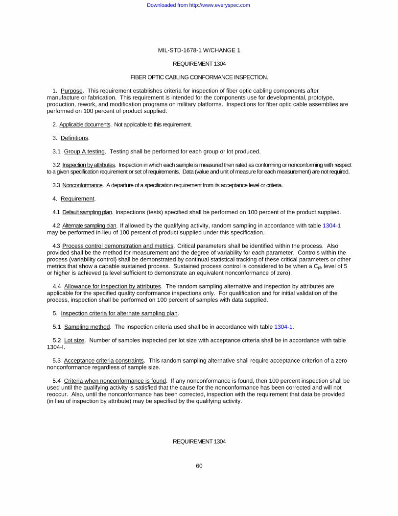
MIL-STD-1678-1 W/CHANGE 1
60
REQUIREMENT 1304
FIBER OPTIC CABLING CONFORMANCE INSPECTION.
1. Purpose. This requirement establishes criteria for inspection of fiber optic cabling components after manufacture or fabrication. This requirement is intended for the components use for developmental, prototype, production, rework, and modification programs on military platforms. Inspections for fiber optic cable assemblies are performed on 100 percent of product supplied. 2. Applicable documents. Not applicable to this requirement. 3. Definitions. 3.1 Group A testing. Testing shall be performed for each group or lot produced. 3.2 Inspection by attributes. Inspection in which each sample is measured then rated as conforming or nonconforming with respect to a given specification requirement or set of requirements. Data (value and unit of measure for each measurement) are not required. 3.3 Nonconformance. A departure of a specification requirement from its acceptance level or criteria. 4. Requirement. 4.1 Default sampling plan. Inspections (tests) specified shall be performed on 100 percent of the product supplied. 4.2 Alternate sampling plan. If allowed by the qualifying activity, random sampling in accordance with table 1304-1 may be performed in lieu of 100 percent of product supplied under this specification. 4.3 Process control demonstration and metrics. Critical parameters shall be identified within the process. Also provided shall be the method for measurement and the degree of variability for each parameter. Controls within the process (variability control) shall be demonstrated by continual statistical tracking of these critical parameters or other metrics that show a capable sustained process. Sustained process control is considered to be when a Cpk level of 5 or higher is achieved (a level sufficient to demonstrate an equivalent nonconformance of zero). 4.4 Allowance for inspection by attributes. The random sampling alternative and inspection by attributes are applicable for the specified quality conformance inspections only. For qualification and for initial validation of the process, inspection shall be performed on 100 percent of samples with data supplied. 5. Inspection criteria for alternate sampling plan. 5.1 Sampling method. The inspection criteria used shall be in accordance with table 1304-1. 5.2 Lot size. Number of samples inspected per lot size with acceptance criteria shall be in accordance with table 1304-I. 5.3 Acceptance criteria constraints. This random sampling alternative shall require acceptance criterion of a zero nonconformance regardless of sample size. 5.4 Criteria when nonconformance is found. If any nonconformance is found, then 100 percent inspection shall be used until the qualifying activity is satisfied that the cause for the nonconformance has been corrected and will not reoccur. Also, until the nonconformance has been corrected, inspection with the requirement that data be provided (in lieu of inspection by attribute) may be specified by the qualifying activity.
REQUIREMENT 1304
Downloaded from http://www.everyspec.com
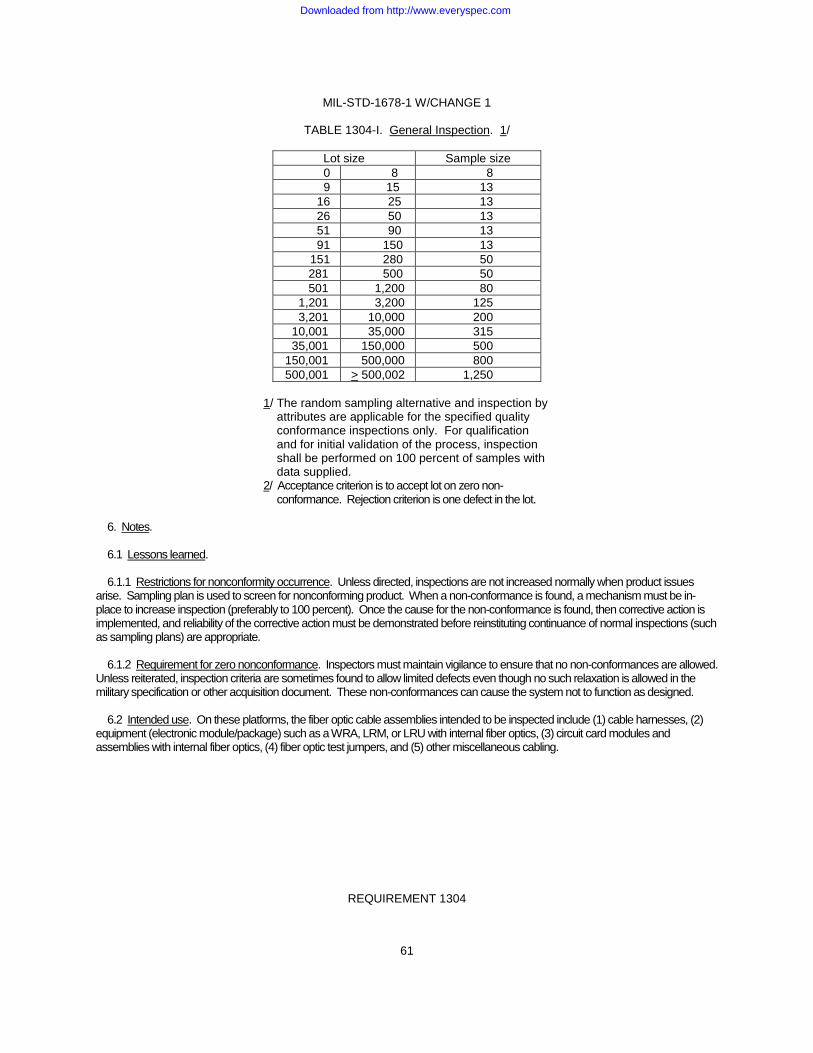
MIL-STD-1678-1 W/CHANGE 1
61
TABLE 1304-I. General Inspection. 1/
Lot size Sample size 0 8 8 9 15 13 16 25 13 26 50 13 51 90 13 91 150 13 151 280 50 281 500 50 501 1,200 80 1,201 3,200 125 3,201 10,000 200 10,001 35,000 315 35,001 150,000 500 150,001 500,000 800 500,001 > 500,002 1,250
1/ The random sampling alternative and inspection by attributes are applicable for the specified quality conformance inspections only. For qualification and for initial validation of the process, inspection shall be performed on 100 percent of samples with data supplied. 2/ Acceptance criterion is to accept lot on zero non- conformance. Rejection criterion is one defect in the lot.
6. Notes. 6.1 Lessons learned. 6.1.1 Restrictions for nonconformity occurrence. Unless directed, inspections are not increased normally when product issues arise. Sampling plan is used to screen for nonconforming product. When a non-conformance is found, a mechanism must be in-place to increase inspection (preferably to 100 percent). Once the cause for the non-conformance is found, then corrective action is implemented, and reliability of the corrective action must be demonstrated before reinstituting continuance of normal inspections (such as sampling plans) are appropriate. 6.1.2 Requirement for zero nonconformance. Inspectors must maintain vigilance to ensure that no non-conformances are allowed. Unless reiterated, inspection criteria are sometimes found to allow limited defects even though no such relaxation is allowed in the military specification or other acquisition document. These non-conformances can cause the system not to function as designed. 6.2 Intended use. On these platforms, the fiber optic cable assemblies intended to be inspected include (1) cable harnesses, (2) equipment (electronic module/package) such as a WRA, LRM, or LRU with internal fiber optics, (3) circuit card modules and assemblies with internal fiber optics, (4) fiber optic test jumpers, and (5) other miscellaneous cabling.
REQUIREMENT 1304
Downloaded from http://www.everyspec.com
MIL-STD-1678-1 W/CHANGE 1
62
CABLING DOCUMENTATION REQUIREMENTS
(1401-1403)
Downloaded from http://www.everyspec.com
MIL-STD-1678-1 W/CHANGE 1
63
REQUIREMENT 1401
FIBER OPTIC CABLING TECHNICAL DOCUMENTATION
1. Purpose. This requirement establishes criteria for demonstrating technical documentation compliance with other requirements covered in part 1 of this Standard Practice. This requirement is intended for developmental, prototype, production, rework, and modification programs on military platform fiber optic cable assemblies. 2. Applicable documents. 2.1 General. The documents listed in this section are specified in sections 3, 4, and 5 of this standard practice. This section does not include documents cited in other sections of this standard practice or recommended for additional information or as examples. While every effort has been made to ensure the completeness of this list, document users are cautioned that they must meet all specified requirements of documents cited in sections 3, 4, and 5 of this standard practice, whether or not they are listed. 2.2 Other Government documents, drawings, and publications. The following other Government documents, drawings, and publications form a part of this standard practice to the extent specified herein. Unless otherwise specified, the issues are these documents are those cited in the solicitation or contract. NAVAIR 01-1A-505-1/ - Technical Manual, Installation and Testing Practices, Aircraft Fiber T.O. 1-1A-14/TM Optic Cabling. 1-1500-232-24-4 (A copy of this document is available online at: https://jswag.navair.navy.mil. At the home page select “Document Library” (on left side), then select the “Committee” folder, then “JFOWG” followed by the “Maintenance Documents” folder. If unable to access this Web Site, request an application by e-mail to NSWC DD Warfare Systems Department at: ([email protected].) 2.3 Order of precedence. Unless otherwise noted herein or in the contract, in the event of a conflict between the text of this document and the references cited herein, the text of this document takes precedence. Nothing in this document, however, supersedes applicable laws and regulations unless a specific exemption has been obtained. 3. Definitions. (Not applicable to this requirement.) 4. General requirement. Data shall be prepared to demonstrate compliance with the requirements covered in part 1 of this Standard Practice. This data shall be in the format as listed in 5 (inspection criteria). Drawings provided shall contain sufficient information to allow a cable to be traced easily. Where practical, fiber optic cabling and electrical cable documentation may be combined. Also, documents shall address the general items listed in 4a through 4e. a. Cable locations. b. Cable identification at bulkhead penetrations, and at those clamps or junctions where cables enter or leave
the cable harness or convoluted tubing. c. Bulkhead penetrations, including location and size of each hole. d. Cable clamping arrangement/design for each cable group where multiple clamps are affixed at one point. e. Installations not performed in accordance with subordinate work package WP 014 01 of NAVAIR 01-1A-505-4/T.O. 1-
1A-14-4/TM 1-1500-323-24-4.
REQUIREMENT 1401
Downloaded from http://www.everyspec.com
MIL-STD-1678-1 W/CHANGE 1
64
5. Inspection criteria. 5.1 Isometric fiber optic cabling diagrams. Isometric fiber optic cabling diagrams shall indicate the relative location of inter-compartment fiber optic cable runs between FOCT system components. For simplicity, racks in which no system equipment is installed may be represented by a platform frame centerline. Long fiber optic cable runs may be simplified by eliminating areas where no equipment is installed and by representing eliminated frame spaces with a broken line. The centerline frame space scale for the diagrams shall not be less than 1.6 mm (.062 inch) per foot or less than 1:200. Compartment outlines for spaces containing FOCT system equipment shall approximate the actual contours and shall be shown to indicate relative location within the aircraft. For clarity, compartments containing multiple items of equipment or in which a number of fiber optic cables, cable bundles, or cable harnesses are installed may be depicted as separate enlarged views. A material list shall be provided. 5.2 Cable running sheets. Cable running sheets shall be provided and may be provided in lieu of elementary or isometric cabling diagrams, subject to the following conditions. The cable harness key plan may be provided as a series of two-dimensional plans; however, a comma-delimited ASCII file giving the three dimensional coordinates of each cable harness checkpoint and penetration shall be developed and provided. The coordinate reference for these dimensions shall be consistent with all other platform’s drawings. Cable running sheets shall be provided in both hard copy and comma-delimited ASCII file formats, with each cable identified on a unique line in the file, followed by the starting point, the checkpoints associated with that cable, and the ending point. 5.3 Fiber optic cabling block diagrams. Fiber optic cabling block diagrams shall be prepared and shall identify equipment and compartments. The diagrams shall be arranged to indicate relative compartment locations; for example: compartments located on the forward part of the platform shall be shown on the right half of the diagram. 5.4 Fiber optic cable topology optical loss budget analysis report. A fiber optic cable topology optical loss (power) budget analysis report shall be prepared to document the optical power budgets for each system that uses the fiber optic cable topology. The fiber optic cable topology optical power budget analysis report shall be developed in accordance with Requirement 1202. 6. Notes. 6.1 Lessons learned. 6.1.1 Design for maintainability. Ensure system design includes development of technical documentation required to revise and maintain the platform. It is critical for the maintainer to have revisions documented to properly maintain the platform. 6.1.2 Design requirements. Define the Interface Control Document (ICD) early in the acquisition process. Program offices anticipating the use of optical fiber should require that the system integrators/prime contractor should develop the ICD (preferably before initial capability demonstration or earlier) and deliver it to the designated government engineering authority as part of the acquisition process. It is in the ICD where the details that allow proper interoperability are defined such as end face geometry on all attachments to the cable plant. Selection of interface devices must be from approved, reputable sources, preferably military specification or MIL-PRF compatible, so as to ensure long operability in diverse/extreme environments. Failure to do so can result in the inability to connect the various systems during integration as well as low reliability, high obsolescence risk resulting in high life cycle costs. 6.2 Intended use. On these platforms, the fiber optic cable assemblies intended to be inspected include (1) cable harnesses, (2) equipment (electronic module/package) such as a WRA, LRM, or LRU with internal fiber optics, (3) circuit card modules and assemblies with internal fiber optics, and (4) other miscellaneous cabling.
REQUIREMENT 1401
Downloaded from http://www.everyspec.com
MIL-STD-1678-1 W/CHANGE 1
65
REQUIREMENT 1402
FIBER OPTIC CABLING MANAGEMENT DOCUMENTATION.
1. Purpose. This requirement establishes criteria for demonstrating management documentation compliance with other requirements covered in part 1 of this Standard Practice. This requirement is intended for developmental, prototype, production, rework, and modification programs on military platform fiber optic cable assemblies. 2. Applicable documents. 2.1 General. The documents listed in this section are specified in sections 3, 4, and 5 of this standard practice. This section does not include documents cited in other sections of this standard practice or recommended for additional information or as examples. While every effort has been made to ensure the completeness of this list, document users are cautioned that they must meet all specified requirements of documents cited in sections 3, 4, and 5 of this standard practice, whether or not they are listed. 2.2 Other Government documents, drawings, and publications. The following other Government documents, drawings, and publications form a part of this standard practice to the extent specified herein. Unless otherwise specified, the issues are these documents are those cited in the solicitation or contract. NAVAIR 01-1A-505-1/ - Technical Manual, Installation and Testing Practices, Aircraft Fiber T.O. 1-1A-14/TM Optic Cabling. 1-1500-232-24-4 (A copy of this document is available online at: https://jswag.navair.navy.mil. At the home page select “Document Library” (on left side), then select the “Committee” folder, then “JFOWG” followed by the “Maintenance Documents” folder. If unable to access this Web Site, request an application by e-mail to NSWC DD Warfare Systems Department at: ([email protected].) 2.3 Order of precedence. Unless otherwise noted herein or in the contract, in the event of a conflict between the text of this document and the references cited herein, the text of this document takes precedence. Nothing in this document, however, supersedes applicable laws and regulations unless a specific exemption has been obtained. 3. Definitions. 3.1 Maintenance spare fiber. This fiber is not allocated for use by any system, but is reserved for use in the case of damage to an allocated fiber. 4. General requirement. A Fiber Optic Cable Topology (FOCT) management system shall be provided for configuration management of the fiber optic topology. The fiber optic cable topology management system shall provide an automated configuration management capability for use by maintenance personnel. This software application shall be a stand-alone passive system. The human-machine interface shall be a Graphical User Interface (GUI). Terminology, symbols, and labeling shall be consistent with work package WP 003 of NAVAIR 01-1A-505-4/T.O. 1-1A-14-4/TM 1-1500-323-24-4. 5. Specific requirements. 5.1 Optical paths. The fiber optic topology management system shall be capable of providing end-to-end graphical representation of optical fiber paths within the fiber optic topology. Textual information associated and displayed for each end-to-end path shall include as a minimum: Individual fiber, cable, junction connection, and connector identification, circuit identification, installed optical loss data, and end user equipment identification. 5.2 Connection junctions. The fiber optic topology management system shall provide schematic representation of each connection junction associated with the fiber optic topology. This schematic representation shall contain the same information as the “as-built” drawings. Information in the fiber optic topology management system shall be capable of being updated as the configuration of the fiber optic topology is changed.
REQUIREMENT 1402
Downloaded from http://www.everyspec.com
MIL-STD-1678-1 W/CHANGE 1
66
5.3 Reconfiguration, sparing and growth. The fiber optic topology management system shall be capable of identification and reporting of reconfiguration options, available spare (including maintenance spare fiber, if applicable) and growth resources. The information contained within the fiber optic topology management system shall use the same database structure and format as the network management system in order to establish a comprehensive network management and damage control situational awareness. 6. Notes. 6.1 Lessons learned. 6.1.1 Design for maintainability. Begin development of the fiber optic maintenance plan early in the process and add greater detail as the design is finalized. Ensure system design includes development of management documentation required to revise and maintain the platform. 6.2 Intended use. On these platforms, the fiber optic cable assemblies intended to be inspected include (1) aircraft cable harnesses, (2) equipment (electronic module/package) such as a WRA, LRM, or LRU with internal fiber optics, (3) circuit card modules and assemblies with internal fiber optics, and (4) other miscellaneous cabling.
REQUIREMENT 1402
Downloaded from http://www.everyspec.com
MIL-STD-1678-1 W/CHANGE 1
67
REQUIREMENT 1403
FIBER OPTIC CABLE HARNESS DRAWINGS.
1. Purpose. This requirement establishes content and format criteria for demonstrating cable harness compliance with other requirements covered in Part 1 of this Standard Practice. This requirement is intended for developmental, prototype, production, rework and modification programs on military platform fiber optic cable assemblies. 2. Applicable documents. 2.1 General. The documents listed in this section are specified in sections 3, 4, and 5 of this standard practice. This section does not include documents cited in other sections of this standard practice or recommended for additional information or as examples. While every effort has been made to ensure the completeness of this list, document users are cautioned that they must meet all specified requirements of documents cited in sections 3, 4, and 5 of this standard practice, whether or not they are listed. 2.2 Government documents. 2.2.1 Specifications, standards, and handbooks. The following specifications, standards, and handbooks form a part of this document to the extent specified herein. Unless otherwise specified, the issues of these documents are those cited in the solicitation or contract. DEPARTMENT OF DEFENSE STANDARDS MIL-STD-790 - Established Reliability And High Reliability Qualified Products List (Qpl) Systems For Electrical, Electronic, And Fiber Optic Parts Specifications. (Copies of these documents are available online at https://assist.daps.dla.mil/quicksearch/ or from the Standardization Document Order Desk, 700 Robbins Avenue, Building 4D, Philadelphia, PA 19111-5094.) 2.3 Other Government documents, drawings, and publications. The following other Government documents, drawings, and publications form a part of this standard practice to the extent specified herein. Unless otherwise specified, the issues are these documents are those cited in the solicitation or contract. NAVAIR 01-1A-505-1/ - Technical Manual, Installation and Testing Practices, Aircraft Fiber T.O. 1-1A-14/TM Optic Cabling. 1-1500-232-24-4 (A copy of this document is available online at: https://jswag.navair.navy.mil. At the home page select “Document Library” (on left side), then select the “Committee” folder, then “JFOWG” followed by the “Maintenance Documents” folder. If unable to access this Web Site, request an application by e-mail to NSWC DD Warfare Systems Department at: ([email protected].) 2.4 Non-Government publications. The following documents form a part of this document to the extent specified herein. Unless otherwise specified, the issues of these documents are those cited in the solicitation or contract. AMERICAN NATIONAL STANDARD INSTITUTE (ANSI International) ANSI Y14.1 - Drawing Sheet Size and Format. ANSI Y14.5 - Dimensioning and Tolerancing. (Copies are available online at http://www.ansi.org or by writing to ANSI International, 25 West 43rd Street, 4th floor, New York, NY 10036.) 2.5 Order of precedence. Unless otherwise noted herein or in the contract, in the event of a conflict between the text of this document and the references cited herein, the text of this document takes precedence. Nothing in this document, however, supersedes applicable laws and regulations unless a specific exemption has been obtained.
REQUIREMENT 1403
Downloaded from http://www.everyspec.com
MIL-STD-1678-1 W/CHANGE 1
68
3. Definitions. 3.1 Fiber optic cable harness. A cable assembly that consists of fiber optic cabling with or without containing cables run to different breakouts (branches) and with fiber optic connectors at the end of each cable run or segment. The cabling may contain a protective cover (protected cable harness) or remain exposed (open cable harness). Types of protective coverings include convoluted tubing (preferred for a fiber optic application) and braid. The connector is usually a multiple termini connector plug/receptacle and configured with connector accessories such as a backshell for cable strain relief, a backshell for affixing the protective covering to the connector, or an EMI retention nut. The type protective covering used must not be one that stresses the cable. 4. General content. A cable harness drawing shall be developed for each specific configuration of the fiber optic cable harness. It shall include all ranges, sizes, connections and other variations listed. The cable harness drawing shall include the following minimum information and shall be developed to address the general items listed in 4.1 through 4.5. Drawing shall be tailored such that those portions of items listed in 4.1 through 4.5 which are not relevant to the specific fiber optic cable harness being acquired/developed shall not be addressed. 4.1 Cable descriptive data. a. Part Identification Number (PIN) for the fiber optic cable harness. The numbering system shall include, but
may not be restricted to, the classification variables. b. Part identification number for replacement parts.
c. Size and other data for proper selection. d. Inspection and test approval data listing the inspections performed and test methods used. e. Statement that the fiber optic cable harness is in accordance with the requirements of the applicable
specification or acquisition document and to reference specifications. f. Exceptions to the specification or acquisition document shall be noted. 4.2 Parts list. a. Item number (corresponding to flag number identifying the part on the drawing). b. Quantity of each part required per assembly. c. Name of part with sufficient information to readily identify the part (for example, screws: thread size, length
and type of head). Also cite the specification, if applicable. d. Material of part. Also cite the material specification, if applicable.
NOTE: When substitution of a material specification is made, it is the responsibility of the vendor to provide written documentation to substantiate that the substituted material is equivalent to the specified material.
e. Type, class, grade, size, military designation, or other classification of any referenced specification. f. Name of actual manufacturer of each part (when applicable). g. PIN of identification assigned by manufacturer or part supplier. h. PIN of identification assigned by assembly supplier (if different). i. Remarks column. Items listed such as finishes, plating, or coating along with the applicable specification or
other requirements.
REQUIREMENT 1403
Downloaded from http://www.everyspec.com
MIL-STD-1678-1 W/CHANGE 1
69
4.3 Details of assembly. a. Two or more representative assembly views, as required, to show clearly the details of the design and
fabrication or assembly of the fiber optic cable harness with each part identified. b. Sectional views, detail views or notes as necessary to show internal details. c. Dimensions of the fiber optic cable harness showing overall and principle dimensions in sufficient detail to
establish space requirements in all directions necessary for installation and servicing. d. Dimensions to show required distances between specific parts. e. Dimensions to ensure interoperability (proper fit) with mating systems. f. Dimensions and tolerances shall be in accordance with ANSI Y14.5. g. Details such as entrance provisions, glands (grommets, gaskets, seals), fastening techniques and other
details as applicable. h. Any special features. i. Complete weight.
j. Location, size and type of connectors used. k. Conformance of cabling components used. Fiber optic cabling components used on the cable harness
shall conform to Requirement 1102 for those components listed. 4.4 Special requirements. These requirements may include, but are not limited to, those specified in 4.4a through 4.4h. a. Requirements to package (bag) and label (tag) the fiber optic cable harness. b. Requirements to place and apply materials such as heat shrink, boots (or other type strain relief), seals and
compounds. c. Requirements to provide dust covers (metal protective caps) and other means to ensure ferrule end face
cleanliness and physical protection. Included is to be one requirement to provide a means to permanently affix dust covers to the cable harness.
d. Requirements to stipulate the optical performance parameters with performance limits at the wavelength(s)
of interest. e. Requirements to place and label cable sleeves with designators specified on the connection diagram. f. Requirements for special fabrication instructions such as deviation of a ferrule end face polish from that to
give a domed ferrule with a PC polish. g. Requirements to show a schematic representation of the cable harness with each pin/socket (equivalent to
electrical junction/plug) termination connection labeled. h. Requirements for specific orientations or directions in which a part must be positioned.
REQUIREMENT 1403
Downloaded from http://www.everyspec.com
MIL-STD-1678-1 W/CHANGE 1
70
4.5 Table for special tools. Special tools required for the fabrication or assembly of the fiber optic cable harness shall be presented in the following tabular form: a. Tool name (description) including generic name. b. Tool specification (if applicable). c. Tool supplier. d. Tool PIN assigned by tool supplier. e. Description of tool’s application. f. Remarks column. Special techniques or other usage requirements shall be explained in this column. 4.6 Inspection and test. 4.6.1 Inspection. Identification of quality control documents which show conformance with MIL-STD-790 or the quality control specification that is listed in the applicable specification or procurement document. The acceptance letter shall be referenced, if applicable. 4.6.2 Optical measurements test. Optical measurements (optical loss, and if applicable, return loss) performed in accordance with requirement 1301 or applicable work package in NAVAIR 01-1A-505-4/T.O. 1-1A-14-4/TM 1-1500-323-24-4. 4.6.3 End face geometry. Inspection performed to ensure connector/terminus ferrule end face geometry is in accordance with Requirement 1302. 4.6.4 Labeling. Inspection performed to ensure fiber optic cable harness labeled in accordance with Requirement 1104. 4.6.5 Cabling components. Inspection performed to ensure fiber optic cable harness components used conform to those specified in Requirement 1102. 4.6.6 Fabrication integrity. When specified, test performed to verify adequate seal integrity, pull strength, and performance parameter. 4.6.7 Data package. Test report number and date, facility where the test was conducted, data sheets, and other test documentation shall be included in a data package supplied with the finished cable harness. 5. Format. 5.1 Title block. The title block shall be included on each drawing sheet and shall include the title, drawing number, revision letter, sheet number, tolerance on dimensions, vendor acceptance block, CAGE Code, scale, reference drawings, vendor (manufacturer or fabricator) name and address, and drawing size. 5.1.1 Title. The title shall consist of the name by which the fiber optic cable harness is known. 5.1.2 Drawing number. The drawing number shall consist of alphanumeric characters which may be separated by dashes or slashes. The total number of characters in the drawing number (including dashes and/or slashes) shall not exceed 15. Blank spaces are not permitted within the drawing number.
REQUIREMENT 1403
Downloaded from http://www.everyspec.com
MIL-STD-1678-1 W/CHANGE 1
71
5.1.3 Revision letter. The revision letter shall denote the latest approved version of the drawing. The revision letter of the drawing shall not be changed until the changes under that revision have been accepted in writing by the authorized Government activity. No change made to the drawing shall be considered a revision until after the initial version of the drawing has been accepted in writing by the authorized government activity. After initial submittal of the drawing, no changes shall be made during the initial drawing review process unless the change is either requested by the authorized Government activity or the change is documented in written correspondence by the vendor. 5.1.4 Sheet number. The sheet number shall be in the format of “Sheet X of Y”. 5.1.5 Tolerance on dimensions. Tolerance shall be listed for fractions, decimals and angles with the units of measure for those dimensions listed on the drawing. 5.1.6 Vendor acceptance block. Appropriate signatures of personnel that prepared, designed or engineered, and approved the drawing with the dates. 5.1.7 CAGE code. Commercial and Government Entity (CAGE) Code for the vendor shall be listed. 5.2 Revision block. A revision block shall be included on each sheet of the drawing and shall contain the revision letter, description of the revision, acceptance letter with serial number and originator identification, and acceptance date. 5.3 Form. Sheet size and format not specified herein shall be in accordance with ANSI Y14.1. 5.4 Classification designation. No Government security classification designation, such as confidential or secret, shall appear on the drawing unless a particular classification is specified by the Government. 6. Notes. 6.1 Lessons learned. 6.1.1 Drawing content. Sufficient drawing content ensures adequate configuration description and delivery of required performance. Drawings with sufficient content and specifying required inspection and test (optical measurement) criteria are one means to ensure a fiber optic cable harness with specified components, proper configuration, and adequate optical performance is obtained. 6.2 Intended use. On these platforms, the fiber optic cable assemblies intended to be inspected are cable harnesses, (1) equipment (electronic module/package) such as a WRA, LRM or LRU with internal fiber optics, (2) circuit card modules and assemblies with internal fiber optics, and (3) other miscellaneous cabling.
REQUIREMENT 1403
Downloaded from http://www.everyspec.com
MIL-STD-1678-1 W/CHANGE 1
72
Custodians: Preparing activity: Army - CR DLA - CC Navy - AS Air Force - 85 (Project 60GP-2010-005) DLA - CC Review activities: Air Force - 99 NOTE: The activities listed above were interested in this document as of the date of this document. Since organizations and responsibilities can change, you should verify the currency of the information above using the ASSIST Online database at https://assist.daps.dla.mil/.
Downloaded from http://www.everyspec.com