methods guide - university of michigan
TRANSCRIPT
ERwin
Methods Guide
© 1997 by Logic Works, Inc.

ERwin Version 3.0
Methods Guide
Logic Works, Inc.
University Square at Princeton
111 Campus Drive
Princeton, NJ 08540
This product is subject to the license agreement and limited warranty enclosed in theproduct package. The product software may be used or copied only in accordance withthe terms of this agreement. Please read the license agreement carefully before openingthe package containing the program media. By opening the media package, you acceptthese terms. If you do not accept or agree to these terms, you may promptly return theproduct with the media package still sealed for a full refund.
Information in this document is subject to change without notice. No part of this manualmay be reproduced or transmitted in any form or by any means, electronic ormechanical, including photocopying and recording, for any purpose without the expresswritten permission of Logic Works.
logicworks®
© Copyright 1989-1997 Logic Works, Inc. All rights reserved.
Printed in the United States of America.
Logic Works, ERwin and BPwin are U.S. registered trademarks of Logic Works, Inc. ModelMart,DataBOT, TESTBytes, ModelBlades, RPTwin and Logic Works with logo are trademarks of LogicWorks, Inc. All other brand and product names are trademarks or registered trademarks of theirrespective owners.

ERwin Methods Guide
Contents • i
Contents
Preface .......................................................................................................... iii
Intended Audience ................................................................................................ ivAbout this Guide ................................................................................................... ivTypographical Conventions................................................................................... v
Chapter 1 Information Systems, Databases, and Models.......................... 9
What’s in This Chapter?......................................................................................... 9What is Data Modeling?....................................................................................... 10Data Modeling Sessions ....................................................................................... 12Sample IDEF1X Modeling Methodology............................................................ 14Logical Models...................................................................................................... 16Physical Models .................................................................................................... 17Benefits of Modeling in ERwin............................................................................ 18
Chapter 2 Constructing a Logical Model .................................................. 19
What’s in This Chapter?....................................................................................... 19The Entity-Relationship Diagram........................................................................ 20Validating the Design of the Logical Model....................................................... 24Data Model Example............................................................................................ 25
Chapter 3 The Key-Based Model ............................................................... 27
What’s in This Chapter?....................................................................................... 27Understanding Keys............................................................................................. 28Relationships and Foreign Key Attributes.......................................................... 32Rolenames ............................................................................................................. 36
ERwin Methods Guide
ii • Contents
Chapter 4 Naming and Defining Entities and Attributes ..........................37What’s in This Chapter?........................................................................................37Naming Entities and Attributes ...........................................................................38Entity Definitions...................................................................................................40Attribute Definitions .............................................................................................43Rolenames ..............................................................................................................44Definitions and Business Rules ............................................................................46
Cahpter 5 Refining Model Relationships...................................................47What’s in This Chapter?........................................................................................47Relationship Cardinality .......................................................................................48Referential Integrity...............................................................................................51Additional Relationship Types.............................................................................56Many-to-Many Relationships ...............................................................................57N-ary Relationships...............................................................................................60Recursive Relationships ........................................................................................62Subtype Relationships...........................................................................................64
Chapter 6 Normalization .............................................................................71Introduction ...........................................................................................................71Overview of the Normal Forms ...........................................................................72Common Design Problems...................................................................................73Unification..............................................................................................................84How Much Normalization Is Enough?................................................................86ERwin Support for Normalization.......................................................................88
Chapter 7 Creating a Physical Model.........................................................91What’s in This Chapter?........................................................................................91Creating a Physical Model ....................................................................................92Denormalization ....................................................................................................93
Chapter 8 Dependent Entity Types ............................................................95Classification of Dependent Entities ....................................................................95
Glossary of Terms.......................................................................................89
Index .............................................................................................................93
ERwin Methods Guide
Contents • iii
Preface
Welcome to data modeling with ERwin. If you have never seen a modelbefore, the ERwin Methods Guide will help you understand what a model is,and what it is good for. If you already have some experience with data anddata models, you know how useful they can be in understanding therequirements of your business. A model can help you design new informationsystems or maintain and modify existing ones.
Data modeling is not something that can be covered in a lot of detail in a shortdocument like this one. But by the time you have read it, you will understandenough, even if you are just a beginner, to put ERwin’s methods to work foryou. Overall, the ERwin Methods Guide has the following purposes:
♦ To provide a basic level of understanding of the data modeling methodused by ERwin that is sufficient to do real database design.
♦ To introduce some of the descriptive power and richness of the IDEF1Xand IE modeling languages supported by ERwin and to provide afoundation for future learning.
♦ To provide additional information so you can better understand ERwin’smodeling features.
This document covers the methods of data modeling supported by ERwin,which include:
♦ IDEF1X. The IDEF1X method was developed by the U.S. Air Force. It isnow used in various governmental agencies, in the aerospace andfinancial industry, and in a wide variety of major corporations.
♦ IE (Information Engineering). The IE method was developed by JamesMartin, Clive Finkelstein, and other IE authorities and is widely deployedin a variety of industries.
Both methods are suited to environments where large scale, rigorous,enterprise-wide data modeling is essential.
ERwin Methods Guide
iv • Contents
Intended AudienceThis manual is intended for:
♦ Novice database designers and data modelers as a primer on datamodeling, and as a guide to using the ERwin methods.
♦ Experienced data modelers and applications developers as a guide toIDEF1X and IE data modeling in ERwin.
♦ Experienced IDEF1X or IE users as a guide to the features of IDEF1X andIE supported by ERwin, and the mapping between these methods.
About this GuideThis document contains seven chapters, an appendix, a glossary, and anindex:
♦ Chapter 1 describes data modeling, provides a sample methodology forcreating a data model, and introduces the benefits of modeling in ERwin.
♦ Chapter 2 describes the creation of an entity-relationship diagram (ERD)and explains both the process and validation of the model. This chapteralso introduces the ideas of entities, attributes, and relationships.
♦ Chapter 3 explains the concept of keys, including candidate keys, primaryand alternate keys, inversion entries, migration of foreign keys, and theuse of rolenames.
♦ Chapter 4 explains the importance of creating accurate names anddefinitions for entities, attributes, and rolenames in the logical model.
♦ Chapter 5 provides additional information about entity relationships,including relationship cardinality and referential integrity. This chapteralso describes additional relationship types, such as many-to-many, n-ary,recursive, and subtype relationships.
♦ Chapter 6 defines normalization and the six normal forms of databasedesign. This chapter also provides solutions to a number of commondesign problems and describes ERwin’s support for normalization.
♦ Chapter 7 describes physical model constructs and the creation of thephysical model from a logical model in ERwin.
♦ Appendix A describes the types of dependent entities, includingcharacteristic, associative, designative, and subtype entities, and their usein a logical model.
ERwin Methods Guide
Contents • v
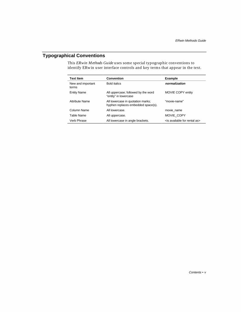
Typographical ConventionsThis ERwin Methods Guide uses some special typographic conventions toidentify ERwin user interface controls and key terms that appear in the text.
Text Item Convention Example
New and importantterms
Bold italics normalization
Entity Name All uppercase; followed by the word“entity” in lowercase
MOVIE COPY entity
Attribute Name All lowercase in quotation marks;hyphen replaces embedded space(s).
“movie-name”
Column Name All lowercase. movie_name
Table Name All uppercase. MOVIE_COPY
Verb Phrase All lowercase in angle brackets. <is available for rental as>

ERwin Methods Guide
vi • Contents

ERwin Methods Guide 1
Information Systems, Databases, and Models • 9
Information Systems, Databases, and Models
What’s in This Chapter?Information systems benefit corporations in numerous ways, from automatingtasks that were previously performed manually, to uncovering informationand relationships that were previously unknown or undefined. In short, thebenefits of information systems can be boiled down to a few key words:faster, better, and more.
However, to realize the benefits of information systems, you must be able todevelop them in a timely and cost effective manner, so that they meet realbusiness needs and can be modified and maintained with minimum expense.Achieving these goals is a major challenge; however, a poorly designedsystem will end up costing more money and time than it saves.
The most important tool in reducing the cost of managing and retrievinginformation has become the relational database management system orRDBMS. An RDBMS provides a reliable and convenient means of storing,retrieving, and updating data.
Equally important is a method that reduces the cost of designing andmanaging relational databases. The most important and widely used methodis called data modeling.
1 ERwin Methods Guide
10 • Information Systems, Databases, and Models
What is Data Modeling?Data modeling is the process of describing information structures andcapturing business rules in order to specify information system requirements.A data model represents a balance between the specific needs of a particularRDBMS implementation project, and the general needs of the business areathat requires it.
Structured system development approaches in general, and data-centereddesign approaches specifically, invest heavily in front-end planning andrequirements analysis activities. Many of these “top-down” designapproaches use ERwin data modeling as a method for identifying anddocumenting the portion of system requirements that relates to data. Processmodels (e.g., data flow diagram sets, distribution models, event/state models)can be created in Logic Works BPwin and other tools to document processingrequirements. Different levels of these models are used during differentdevelopment phases.
When created with the full participation of business and systemsprofessionals, the data model can provide many benefits. These benefitsgenerally fall into two classes: 1) those primarily associated with the model(the product of the effort) and 2) those associated with the process of creatingthe model (the effort).
Examples of product benefits:
♦ A data model is implementation-independent, so it does not require thatthe implementation is in any particular database or programminglanguage.
♦ A data model is an unambiguous specification of what is wanted.
♦ The model is business user-driven. The content and structure of the modelare controlled by the business client rather than the system developer. Theemphasis is on requirements rather than constraints or solutions.
♦ The terms used in the model are stated in the language of the business,not that of the system development organization.
♦ The model provides a context to focus discussions on what is important tothe business.
Examples of process benefits:
♦ During early project phases, model development sessions bring togetherindividuals from many parts of the business and provide a structuredforum in which business needs and policies are discussed. During thesesessions, it is often the case that the business staff, for the first time, meets
ERwin Methods Guide 1
Information Systems, Databases, and Models • 11
others in different parts of the organization who are concerned with thesame needs.
♦ Sessions lead to development of a common business language withconsistent and precise definitions of terms used. Communication amongparticipants is greatly increased.
♦ Early phase sessions provide a mechanism for exchanging large amountsof information among business participants and transferring muchbusiness knowledge to the system developers. Later phase sessionscontinue that transfer of knowledge to the staff who will implement thesolution.
♦ Session participants are generally able to better see how their activities fitinto a larger context. And parts of the project can be seen in the context ofthe whole. The emphasis is on “cooperation” rather than “separation.”Over time, this can lead to a shift in values, and the reinforcement of acooperative philosophy.
♦ Sessions foster consensus and build teams.
Design of the data structures to support a business area is only one part ofdeveloping a system. The analysis of processes (function) is equallyimportant. Function models describe “how” something is done. They can bepresented as hierarchical decomposition charts, data flow diagrams, HIPOdiagrams, etc. You will find, in practice, that it is important to develop bothyour function models and data models at the same time. Discussion of thefunctions to be performed by the system uncovers the data requirements.Discussion of the data normally uncovers additional function requirements.Function and data are the two sides of the system development coin.
ERwin provides direct support for process modeling and can work well withmany techniques. For example, Logic Works also provides BPwin, a functionmodeling tool that supports IDEF0, IDEF3 workflow, and data flow diagrammethods and can be used in conjunction with ERwin to complete an analysisof process during a data modeling project.
1 ERwin Methods Guide
12 • Information Systems, Databases, and Models
Data Modeling SessionsCreating a data model involves not only construction of the model, but alsonumerous fact-finding sessions that uncover the data and processes used by abusiness. Running good sessions, like running good meetings of any kind,depends on a lot of preparation and “real-time” facilitation techniques. Ingeneral, modeling sessions should include the right mix of business andtechnical experts and should be facilitated. This means that modeling sessionsare scheduled well in advance, carefully planned to cover sets of focusedmaterial, and orchestrated in such a way that desired results are achieved.
When possible, it is highly recommended that modeling of function and databe done at the same time. This is because functional models tend to validate adata model and uncover new data requirements. This approach also ensuresthat the data model supports function requirements. To create both a functionmodel and data model in a single modeling session, it is important to includea data modeler and a process modeler who are responsible for capturing thefunctions being explored.
Session RolesFormal, guided sessions, with defined roles for participants and agreed uponprocedures and rules, are a must. The following roles work well:
♦ The facilitator is the session guide. This person is responsible forarranging the meetings and facilities, providing follow-up documentation,and intervening during sessions, as necessary, to keep sessions on trackand to control the scope of the session.
♦ The data modeler is responsible for leading the group through the processof developing and validating the model. The modeler develops the model,in real-time if possible, in front of the group by asking pertinent questionsthat bring out the important details and recording the resulting structurefor all to see. It is often possible (although somewhat difficult) for thesame individual to play both facilitator and data modeler roles.
♦ The data analyst functions as the scribe for the session and records thedefinitions of all entities and attributes that make up the model. Based oninformation from the business experts, the data analyst can also begin to“package” entities and attributes into subject areas, manageable andmeaningful subsets of the complete data model.

ERwin Methods Guide 1
Information Systems, Databases, and Models • 13
♦ The subject matter experts in the business provide the businessinformation needed to construct the model. They are “business” not“systems” people.
♦ The manager, either from the “systems” or “business” community,participates in the sessions in an assigned role (facilitator, subject matterexpert, etc.) but has the additional responsibility of making decisions asneeded to keep the process moving. The manager has the responsibility of“breaking ties” but only when absolutely necessary.

1 ERwin Methods Guide
14 • Information Systems, Databases, and Models
Sample IDEF1X Modeling MethodologyERwin has been developed to support the IDEF1X and IE modelingstandards. The use of various levels of models within the IDEF1X method canbe very helpful in developing a system. General model levels are outlined inthe IDEF1X standard and are presented below. In practice, you may find ituseful to expand or contract the number of levels to fit individual situations.
The model levels generally span a from very wide but not too detailed view ofthe major entities that are important to a business down to a level of precisionrequired to represent the database design in terms understandable by aparticular DBMS. At the very lowest level of detail, models are said to betechnology dependent, e.g., a model for an IMS database will look verydifferent from a model for a DB2 database. At higher levels, models aretechnology independent and may even represent information which is notstored in any automated system.
The modeling levels presented below are well suited to a top-down systemdevelopment life cycle approach, in which successive levels of detail arecreated during each project phase.
The highest level models come in two forms: Entity Relationship Diagram(ERD) and Key-Based (KB). The Entity Relationship Diagram (ERD) identifiesmajor business entities and their relationships. The Key-Based (KB) Modelsets the scope of the business information requirement (all entities areincluded) and begins to expose the detail.
The lower level models also come in two forms: Fully Attributed (FA) andTransformation Model (TM). The Fully Attributed (FA) Model is a thirdnormal form model which contains all of the detail for a particularimplementation effort. The Transformation Model (TM) represents atransformation of the relational model into a structure which is appropriate tothe DBMS chosen for implementation.
The Transformation Model, in most cases, is no longer in third normal form.The structures have been optimized based on the capabilities of the DBMS,the data volumes, and the expected access patterns and rates against the data.In a sense, this is a picture of the eventual physical database design.
The database design is contained in the DBMS Model for the system.Depending on the level of integration of the information systems of abusiness, the DBMS Model may be a project level model or an area levelmodel for the entire integrated system.

ERwin Methods Guide 1
Information Systems, Databases, and Models • 15
These five modeling levels are presented in the figure below. Notice that theDBMS Model can be either at an “Area Level” scope, or a “Project Level”scope. It would not be uncommon to have single ERD and KB models for abusiness and multiple DBMS Models, one for each implementationenvironment, and then another set within that environment for “projects”which do not share databases. In an ideal situation, there are a set of “AreaLevel” scope DBMS Models, one for each environment, with complete datasharing across all projects in that environment.
IDEF1X Database Design Levels
1 ERwin Methods Guide
16 • Information Systems, Databases, and Models
Logical ModelsThere are three levels of logical models that are used to capture businessinformation requirements: the Entity Relationship Diagram (ERD), the Key-Based (KB) Model, and the Fully Attributed(FA) model. The ERD and KBmodels are also called “area data models” because they often cover a widebusiness area that is larger than the business chooses to address with a singleautomation project. In contrast, the FA model is a “project data model”because it typically describes a portion of an overall data structure intendedfor support by a single automation effort.
The Entity Relationship DiagramThe Entity Relationship Diagram is a high level data model that shows themajor entities and relationships which support a wide business area. This isprimarily a presentation or discussion model.
The objective of the entity relationship diagram is to provide a view ofbusiness information requirements sufficient to satisfy the need for broadplanning for development of its information system. These models are notvery detailed (only major entities are included) and there is not much detail, ifany, on attributes. Many-to-many (non-specific) relationships are allowed andkeys are generally not included.
The Key-Based ModelA Key-Based Model describes the major data structures which support a widebusiness area. All entities and primary keys are included along with sampleattributes.
The objective of the key-based model is to provide a broad business view ofdata structures and keys needed to support the area. This model provides acontext in which detailed implementation level models can be constructed.The model covers the same scope as the Area ERD, but exposes more of thedetail.
The Fully-Attributed (FA) ModelA Fully Attributed Model is a third normal form data model that includes allentities, attributes, and relationships needed by a single project. The modelincludes entity instance volumes, access paths and rates, and expectedtransaction access patterns across the data structure.

ERwin Methods Guide 1
Information Systems, Databases, and Models • 17
Physical ModelsThere are also two levels of physical models for an implementation project:the Transformation Model and the DBMS Model. The physical modelscapture all of the information that systems developers need to understandand implement a logical model as a database system. The TransformationModel is also a “project data model” that describes a portion of an overalldata structure intended for support by a single automation effort. ERwinsupports individual projects within a business area, allowing the modeler toseparate a larger area model into submodels, called subject areas. Subjectareas can be developed, reported on, and generated to the database inisolation from the area model and other subject areas in the model.
The Transformation ModelThe objectives of the transformation model are to provide the DatabaseAdministrator (DBA) with sufficient information to create an efficient physicaldatabase, to provide a context for the definition and recording of the dataelements and records that form the database in the data dictionary, and tohelp the application team choose a physical structure for the programs thatwill access the data.
When deemed appropriate for the development effort, the model can alsoprovide the basis for comparing the physical database design against theoriginal business information requirements to:
♦ Demonstrate that the physical database design adequately supports thoserequirements.
♦ Document physical design choices and their implications (e.g., what issatisfied, and what is not).
♦ Identify database extensibility capabilities and constraints.
The DBMS ModelThe Transformation Model directly translates into a DBMS model, whichcaptures the physical database object definitions in the RDBMS schema ordatabase catalog. ERwin directly supports this model with its schemageneration function. Primary keys become unique indices. Alternate keys andinversion entries also may become indices. Cardinality can be enforced eitherthrough the referential integrity capabilities of the DBMS, application logic, or“after the fact” detection and repair of violations.

1 ERwin Methods Guide
18 • Information Systems, Databases, and Models
Benefits of Modeling in ERwinRegardless of the type of DBMS you use or which types of data models youwish to develop, modeling your database in ERwin has many benefits. Themost obvious benefit is system documentation that can be used by databaseand application development staff to define system requirements and tocommunicate among themselves and with end-users.
A second benefit is to provide a clear picture of referential integrityconstraints. Maintaining referential integrity is essential in the relationalmodel where relationships are encoded implicitly.
A third benefit is the provision of a “logical” RDBMS-independent picture ofyour database that can be used by automated tools to generate RDBMS-specific information. This way, you can use a single ERwin diagram togenerate DB2 table schemas, as well as schemas for other relational DBMSs.
One of the primary benefits of data modeling with ERwin is the ease withwhich you will be able to produce a diagram summarizing the results of yourdata modeling efforts and generate a database schema from that model.

ERwin Methods Guide 2
Constructing a Logical Model • 19
Constructing a Logical Model
What’s in This Chapter?The first step in constructing a logical model is developing the EntityRelationship Diagram (ERD), a high level data model of a wide business area.An entity-relationship diagram is made up of three main building blocks:entities, attributes, and relationships. If you view a diagram as a graphicallanguage for expressing statements about your business, entities are thenouns, attributes are the adjectives or modifiers, and relationships are theverbs. Building a data model with ERwin is simply a matter of finding theright collection of nouns, verbs, and adjectives and putting them all together.
The objective of the ERD is to provide a broad view of business informationrequirements sufficient to plan for development of the business informationsystem. These models are not very detailed (only major entities are included)and there is not much detail, if any, on attributes. Many-to-many (non-specific) relationships are allowed and keys are generally not included. This isprimarily a presentation or discussion model.
ERDs are also divided into subject areas, which are used to define “businessviews” or specific areas of interest to individual business functions. Subjectareas help reduce larger models into smaller, more manageable subsets ofentities that can be more easily defined and maintained.
There are many methods available for developing the ERD. These range fromformal modeling sessions (described in the previous chapter) to individualinterviews with business managers who have responsibility for wide areas.
This chapter introduces the data modeling method used by ERwin andprovides a brief overview of its richness and power for describing theinformation structures of your business.

2 ERwin Methods Guide
20 • Constructing a Logical Model
The Entity-Relationship DiagramIf you are familiar with a relational database structure, you know that themost fundamental component of a relational database is the table. Tables areused to organize and store information. A table is organized in columns androws of data. Each row contains a set of facts called an instance of the table.
In a relational database, all data values must also be atomic, which means thateach cell in the table can contain only a single fact. There is also a relationshipbetween the tables in the database. Each relationship is represented in anRDBMS by sharing one or more columns in two tables.
Like the tables and columns that make up a physical model of a relationaldatabase, an entity-relationship diagram (and all other logical data models)includes equivalent components that let you model the data structures of thebusiness, rather than the database management system. The logical equivalentto a table is an entity, and the logical equivalent to a column is an attribute.
In an ERD, the entity is represented by drawing a box that contains the nameof the entity. Entity names are always singular — CUSTOMER notCUSTOMERS, MOVIE not MOVIES, COUNTRY not COUNTRIES. By alwaysusing singular nouns, you gain the benefit of a consistent naming standardand facilitate “reading” the diagram as a set of declarative statements aboutentity instances.
The diagram below is one created by a hypothetical video store that needs totrack its customers, movies that can be rented or purchased, and rental copiesof movies that are in stock in the store.
Sample Entity-Relationship Diagram
Relationships between tables are a vital component of a relational database.These relationships are captures using shared key: facts in one table refer to,or are associated with, facts in another table. In an ERD, a relationship isrepresented by a line drawn between the entities in the model. A relationshipbetween two entities also implies that facts in one entity refer to, or areassociated with, facts in another entity.

ERwin Methods Guide 2
Constructing a Logical Model • 21
In the example above, the video store needs to track information aboutCUSTOMERs and MOVIE RENTAL COPYs. The information in these twoentities is related, and this relationship can be expressed in a statement: ACUSTOMER rents one or more MOVIE RENTAL COPYs.
Defining Entities and AttributesAn entity is any person, place, thing, event, or concept about whichinformation is kept. More precisely, an entity is a set or collection of likeindividual objects called instances. An instance is a single occurrence of agiven entity. Each instance must have an identity distinct from all otherinstances.
In the previous example, the CUSTOMER entity represents the set of all of thepossible customers of a business. Each instance of the CUSTOMER entity is acustomer. You can list information for an entity in a sample instance table,such as the one shown below.
CUSTOMER
customer-id customer-name customer-address
10001 Ed Green Princeton, NJ
10011 Margaret Henley New Brunswick, NJ
10012 Tomas Perez Berkeley, CA
17886 Jonathon Walters New York, NY
10034 Greg Smith Princeton, NJ
Sample Instance Table for the CUSTOMER Entity
Each instance represents a set of “facts” about the related entity. In the sampleabove, each instance of the CUSTOMER entity includes information on the“customer-id,” “customer-name,” and “customer-address.” In a logicalmodel, these properties are called the attributes of an entity. Each attributecaptures a single piece of information about the entity.

2 ERwin Methods Guide
22 • Constructing a Logical Model
You can include attributes in an ERD to describe the entities in the modelmore fully, as shown below:
ERD with Attributes
Logical RelationshipsRelationships represent connections, links, or associations between entities.They are the “verbs” of a diagram showing how entities relate to each other.Easy-to-understand rules help business professionals validate data constraintsand ultimately identify relationship cardinality.
Here are some examples:
♦ A TEAM <has> many PLAYERs.
♦ A PLANE-FLIGHT <transports> many PASSENGERs.
♦ A DOUBLES-TENNIS-MATCH <requires> exactly 4 PLAYERs.
♦ A HOUSE <is owned by> one or more OWNERs.
♦ A SALESPERSON <sells> many PRODUCTs.
In all of these cases, the relationships are chosen so that the connectionbetween the two entities is what is known as one-to-many. This means thatone (and only one instance) of the first entity is related or connected to manyinstances of the second entity. The entity on the “one-end” is called the parententity. The entity on the “many-end” is called the child entity.

ERwin Methods Guide 2
Constructing a Logical Model • 23
Relationships are displayed as a line connecting two entities, with a dot onone end, and a verb phrase written along the line. In the previous examples,the verb phrases are the words inside the brackets (e.g., <sells>). Here is adiagram of the relationship between PLANE-FLIGHTs and PASSENGERs onthat flight.
Relationship Example
Many-to-Many RelationshipsA many-to-many relationship, also called a non-specific relationship,represents a situation where an instance in one entity relates to one or moreinstances in a second entity and an instance in the second entity also relates toone or more instances in the first entity. In the video store example, a many-to-many relationship occurs between a CUSTOMER and a MOVIE COPY.From a conceptual point of view, this many-to-many relationship indicatesthat “A CUSTOMER <rents> many MOVIE COPYs” and “A MOVIE COPY<is rented by> many CUSTOMERs.”
Example of a Many-to-Many Relationship in IDEF1X (top) and IE (bottom)
Many-to-many relationships tend to be used in a preliminary stage of diagramdevelopment, such as in an entity-relationship diagram (ERD), and arerepresented in IDEF1X as a solid line with dots on both ends.
Because a many-to-many relationship can hide other business rules orconstraints, they should be fully explored at some point in the modelingprocess. For example, sometimes a many-to-many relationship identified inearly modeling stages is mislabeled and is actually two one-to-many
2 ERwin Methods Guide
24 • Constructing a Logical Model
relationships between related entities. Or, the business must keep additionalfacts about the many-to-many relationship, such as dates or comments, andthe result is that the many-to-many relationship must be replaced by anadditional entity to keep these facts. All many-to-many relationships need tobe fully discussed at later modeling stages to ensure that the relationship iscorrectly modeled.
Validating the Design of the Logical ModelIf you choose your verb phrases correctly, you should be able to “read” arelationship from the parent to the child using an “active” verb phrase. One ofthe previous examples reads as:
A PLANE FLIGHT <transports> many PASSENGERs.
Verb phrases can also be read from the perspective of the child entity. You canoften read from the child entity perspective using “passive” verb phrases. Forexample:
Many PASSENGERs <are transported by> a PLANE FLIGHT.
Because a data model exposes many of the business rules that describe thearea being modeled, reading the relationships helps you validate that thedesign of the logical model is correct. Verb phrases provide a brief summaryof the business rules embodied by relationships. And although they do notprecisely describe the rules, verb phrases provide an initial sense of how theentities are connected.
It is a good practice to make sure that each verb phrase in the model results invalid statements. Reading your model back to the business analysts andsubject matter experts is one of the primary methods of verifying that itcorrectly captures the business rules.
ERwin Methods Guide 2
Constructing a Logical Model • 25
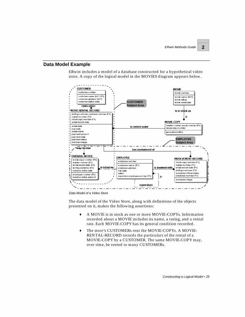
Data Model ExampleERwin includes a model of a database constructed for a hypothetical videostore. A copy of the logical model in the MOVIES diagram appears below.
EMPLOYEESubject Area
CUSTOMERSubject Area
Data Model of a Video Store
The data model of the Video Store, along with definitions of the objectspresented on it, makes the following assertions:
♦ A MOVIE is in stock as one or more MOVIE-COPYs. Informationrecorded about a MOVIE includes its name, a rating, and a rentalrate. Each MOVIE-COPY has its general condition recorded.
♦ The store’s CUSTOMERs rent the MOVIE-COPYs. A MOVIE-RENTAL-RECORD records the particulars of the rental of aMOVIE-COPY by a CUSTOMER. The same MOVIE-COPY may,over time, be rented to many CUSTOMERs.

2 ERwin Methods Guide
26 • Constructing a Logical Model
♦ Each MOVIE-RENTAL-RECORD also records a due date for themovie and a status indicating whether or not it is overdue.Depending on a CUSTOMER’s previous relationship with the store,a CUSTOMER is assigned a credit status code which indicateswhether the store should accept checks or credit cards for payment,or accept only cash.
♦ The store’s EMPLOYEEs are involved with many MOVIE-RENTAL-RECORDs, as specified by an involvement type. There must be atleast one EMPLOYEE involved with each record. Since the sameEMPLOYEE might be involved with the same rental record severaltimes on the same day, involvements are further distinguished by atime stamp.
♦ An overdue charge is sometimes collected on a rental of a MOVIE-COPY. OVERDUE-NOTICEs are sometimes needed to remind aCUSTOMER that a tape needs to be returned. An EMPLOYEE issometimes listed on an OVERDUE-NOTICE.
♦ The store keeps salary and address information about each of itsEMPLOYEEs. It sometimes needs to look up CUSTOMERs,EMPLOYEEs, and MOVIEs by their names, rather than by their“numbers.”
This is a relatively small model, but it says a lot about the video rental store.From it, you not only can get an idea of what a database for the businessshould look like, you also get a good picture of the business. There are severaldifferent types of graphical “objects” in this diagram. The entities, attributes,and relationships, along with the other symbols, describe our business rules.In the following chapters, you will learn more about what the differentgraphical objects mean and how to use ERwin to create your own logical andphysical data models.
ERwin Methods Guide 3
The Key-Based Model • 27
The Key-Based Model
What’s in This Chapter?A Key-Based Model (KB) is a data model that fully describes all of the majordata structures that support a wide business area. The goal of a key-basedmodel is to include all entities and attributes that are of interest to thebusiness.
As their name suggests, key-based models also include keys, which are theelements of the data model that are used to identify unique instances withinan entity and, when implemented in a physical model, provide easy access tothe underlying data.
Basically, the key-based model covers the same scope as the ERD but exposesmore of the detail, including the context in which detailed implementationlevel models can be constructed.
3 ERwin Methods Guide
28 • The Key-Based Model
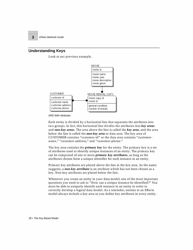
Understanding KeysLook at our previous example.
ERD With Attributes
Each entity is divided by a horizontal line that separates the attributes intotwo groups. In fact, this horizontal line divides the attributes into key areasand non-key areas. The area above the line is called the key area, and the areabelow the line is called the non-key area or data area. The key area ofCUSTOMER contains “customer-id” or the data area contains “customer-name,” “customer-address,” and “customer-phone.”
The key area contains the primary key for the entity. The primary key is a setof attributes used to identify unique instances of an entity. The primary keycan be comprised of one or more primary key attributes, as long as theattributes chosen form a unique identifier for each instance in an entity.
Primary key attributes are placed above the line in the key area. As the namesuggests, a non-key attribute is an attribute which has not been chosen as akey. Non-key attributes are placed below the line.
Whenever you create an entity in your data model, one of the most importantquestions you need to ask is: “How can a unique instance be identified?” Youmust be able to uniquely identify each instance in an entity in order tocorrectly develop a logical data model. As a reminder, entities in an ERwinmodel always include a key area so you define key attributes in every entity.
ERwin Methods Guide 3
The Key-Based Model • 29
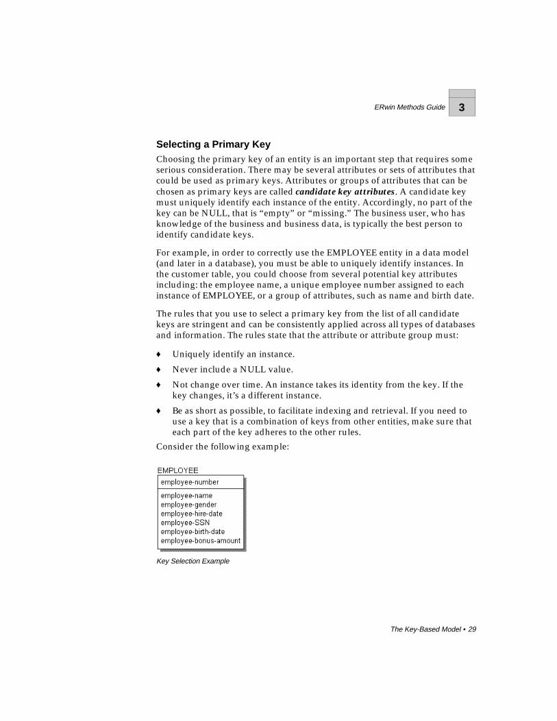
Selecting a Primary KeyChoosing the primary key of an entity is an important step that requires someserious consideration. There may be several attributes or sets of attributes thatcould be used as primary keys. Attributes or groups of attributes that can bechosen as primary keys are called candidate key attributes. A candidate keymust uniquely identify each instance of the entity. Accordingly, no part of thekey can be NULL, that is “empty” or “missing.” The business user, who hasknowledge of the business and business data, is typically the best person toidentify candidate keys.
For example, in order to correctly use the EMPLOYEE entity in a data model(and later in a database), you must be able to uniquely identify instances. Inthe customer table, you could choose from several potential key attributesincluding: the employee name, a unique employee number assigned to eachinstance of EMPLOYEE, or a group of attributes, such as name and birth date.
The rules that you use to select a primary key from the list of all candidatekeys are stringent and can be consistently applied across all types of databasesand information. The rules state that the attribute or attribute group must:
♦ Uniquely identify an instance.
♦ Never include a NULL value.
♦ Not change over time. An instance takes its identity from the key. If thekey changes, it’s a different instance.
♦ Be as short as possible, to facilitate indexing and retrieval. If you need touse a key that is a combination of keys from other entities, make sure thateach part of the key adheres to the other rules.
Consider the following example:
Key Selection Example
3 ERwin Methods Guide
30 • The Key-Based Model
If you use the rules listed above to find candidate keys for EMPLOYEE, youmight compose the following analysis of each attribute:
♦ Because it is unique for all EMPLOYEEs, “employee-number” is acandidate key.
♦ “Employee-name” does not look like a good candidate. There may bemore than one John Smith in the company.
♦ “Employee-social-security-number” is unique in most instances, but everyEMPLOYEE may not have one.
♦ The combination of “employee-name” and “employee-birth-date” mightwork (unless there is more than one John Smith born on the same dateand employed by our company). This could be a candidate key.
♦ Only some EMPLOYEEs of our company are eligible for annual bonuses.Therefore, “employee-bonus-amount” can be expected to be NULL inmany cases. As a result, it cannot be part of any candidate key.
After analysis, there are two candidate keys — one is “employee-number”and the other is the group of attributes containing “employee-name” and“employee-birth-date.” Because it is the shortest and ensures uniqueness ofinstances, “employee-number” is selected as the primary key.
When choosing the primary key for an entity, modelers often assign asurrogate key, an arbitrary number that is assigned to an instance to uniquelyidentify it within an entity. “Employee-number” is an example of a surrogatekey. A surrogate key is often the best choice for a primary key because it isshort, can be accessed the fastest, and ensures unique identification of eachinstance. Further, a surrogate key can be automatically generated by thesystem so that numbering is sequential and does not include any gaps.
A primary key chosen for the logical model may not be the primary keyneeded to efficiently access the table in a physical model. The primary key canbe changed to suit the needs and requirements of the physical model anddatabase at any point.

ERwin Methods Guide 3
The Key-Based Model • 31
Designating Alternate Key AttributesCandidate keys not selected as primary keys can be designated as alternatekeys, and recorded as such in the model. The symbol (AKn), where n is anumber, is placed after those attributes which form the alternate key.Alternate keys are often used to show different indexes the business will useto access the data. So our logical model for EMPLOYEE appears as follows:
Alternate Key Example
Inversion Entry AttributesBusinesses also need to keep track of attributes that are not unique, but areroutinely used to look up information for the entity. These attributes arecalled inversion entries. An inversion entry is an attribute or group ofattributes that are commonly used to access the entity (as though they are aprimary key), but may not result in finding exactly one instance.
For example, the business might want to be able to look up an employee byname, as well as the employee number. Although a search on a name mayresult in one, two, or more records, it is still a business requirement thatemployee records can also be accessed using the employee name. When youassign the attribute to an inversion entry, an IEn is placed after the“employee-name” attribute, as shown below. There can be several inversionentries for an entity.
Inversion Entry Example
3 ERwin Methods Guide
32 • The Key-Based Model
Relationships and Foreign Key AttributesJust as a RDBMS captures relationships using shared key values, ERwin alsorepresents relationships using shared keys. Although ERwin certainly can beused to model information that is stored in non-relational databasemanagement systems, in its treatment of keys, ERwin is relational.
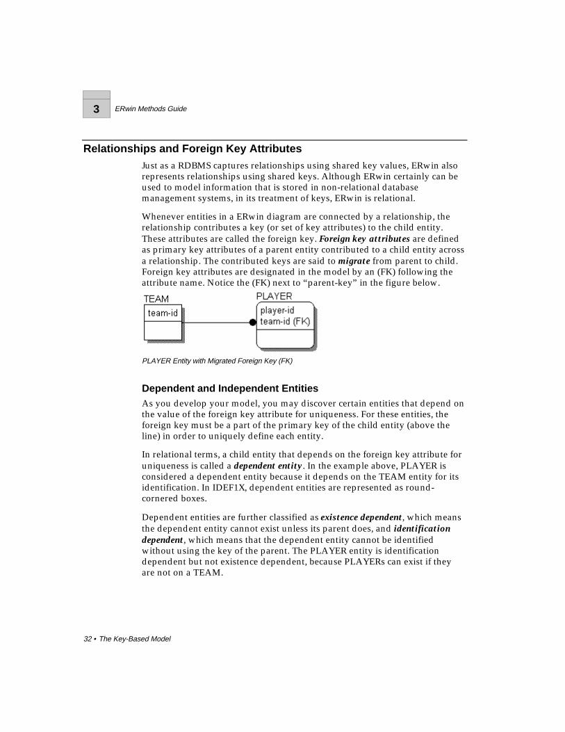
Whenever entities in a ERwin diagram are connected by a relationship, therelationship contributes a key (or set of key attributes) to the child entity.These attributes are called the foreign key. Foreign key attributes are definedas primary key attributes of a parent entity contributed to a child entity acrossa relationship. The contributed keys are said to migrate from parent to child.Foreign key attributes are designated in the model by an (FK) following theattribute name. Notice the (FK) next to “parent-key” in the figure below.
PLAYER Entity with Migrated Foreign Key (FK)
Dependent and Independent EntitiesAs you develop your model, you may discover certain entities that depend onthe value of the foreign key attribute for uniqueness. For these entities, theforeign key must be a part of the primary key of the child entity (above theline) in order to uniquely define each entity.
In relational terms, a child entity that depends on the foreign key attribute foruniqueness is called a dependent entity. In the example above, PLAYER isconsidered a dependent entity because it depends on the TEAM entity for itsidentification. In IDEF1X, dependent entities are represented as round-cornered boxes.
Dependent entities are further classified as existence dependent, which meansthe dependent entity cannot exist unless its parent does, and identificationdependent, which means that the dependent entity cannot be identifiedwithout using the key of the parent. The PLAYER entity is identificationdependent but not existence dependent, because PLAYERs can exist if theyare not on a TEAM.

ERwin Methods Guide 3
The Key-Based Model • 33
In contrast, there are situations in which an entity is existence dependent onanother entity. Consider two entities: ORDER, which the business uses totrack customer orders, and LINE ITEM, which tracks individual items in anORDER. The relationship between these two entities can be expressed as AnORDER <contains> one or more LINE ITEMS. In this case, LINE ITEM isexistence dependent on ORDER, because it makes no sense in the businesscontext to track LINE ITEMS unless there is a related ORDER.
Entities that do not depend on any other entity in the model for identificationare called independent entities. In the example above, TEAM is considered anindependent entity. In IE and IDEF1X, independent entities are represented assquare-cornered boxes.
Identifying RelationshipsIn IDEF1X, the concept of dependent and independent entities is enforced bythe type of the relationship that connects two entities. If you want the foreignkey to migrate to the key area of the child entity (and create a dependententity as a result), you can create an identifying relationship between theparent and child entities.
Identifying relationships are indicated by a solid line connecting the entities.In IDEF1X, the line includes a dot on the end nearest to the child entity, asshown below. In IE, the line includes a “crow’s foot” at the end of therelationship nearest to the child entity.
Identifying Relationship in IDEF1X Notation (top) and IE Notation (bottom)
Note : Standard IE notation does not include rounded corners on entities. This is anIDEF1X symbol that is included in IE notation in ERwin to ensure compatibilitybetween methods.

3 ERwin Methods Guide
34 • The Key-Based Model
As you saw in the discussion of independent and dependent entities, thebusiness rule that indicates that a relationship is identifying results from anintentional choice to identify the child entity by using the identifier of theparent entity. In this example of MOVIEs and MOVIE-COPYs, the copy couldhave been identified by its own unique number. Instead, the identifier of theMOVIE is used and a second part (copy-number) is added to tell one copyfrom another.
Note : As you may find, there are advantages to contributing keys to a child entitythrough identifying relationships in that it tends to make some physical systemqueries more straightforward, but there are also many disadvantages. Someadvanced relational theory suggests that contribution of keys should not occur inthis way. Instead, each entity should be identified not only by its own primarykey, but also by a logical handle or surrogate key, never to be seen by the userof the system. There is a strong argument for this in theory and those who areinterested are urged to review the work of E. F. Codd and C. J. Date in thisarea.
Non-Identifying RelationshipsNon-identifying relationships, which are unique to the IDEF1X notation, alsoconnect a parent entity to a child entity. Non-identifying relationship are usedto show a different migration of the foreign key attribute(s), that is, migrationto the data area of the child entity (below the line).
Non-identifying relationships are indicated by a dashed line connecting theentities. If you connect the TEAM and PLAYER entities in a non-identifyingrelationship, the model appears as shown below.
Non-Identifying Relationship in IDEF1X Notation (top) and IE Notation (bottom)

ERwin Methods Guide 3
The Key-Based Model • 35
Because the migrated keys in a non-identifying relationship are not part of theprimary key of the child, non-identifying relationships do not result in anyidentification dependency. In this case, PLAYER is considered an independententity, just like TEAM.
However, the relationship can reflect existence dependency if the businessrule for the relationship specifies that the foreign key cannot be NULL(“missing”). If the foreign key must exist, this implies that an instance in thechild entity can only exist if an associated parent instance also exists.
Note : Identifying and non-identifying relationships are not a feature of the IE method.However, this information is included in your ERwin diagram in the form of asolid or dashed relationship line to ensure compatibility between IE and IDEF1Xmethods.
3 ERwin Methods Guide
36 • The Key-Based Model
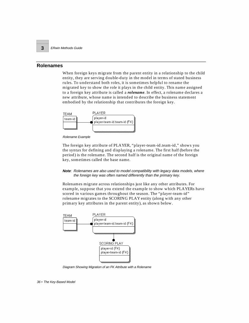
RolenamesWhen foreign keys migrate from the parent entity in a relationship to the childentity, they are serving double-duty in the model in terms of stated businessrules. To understand both roles, it is sometimes helpful to rename themigrated key to show the role it plays in the child entity. This name assignedto a foreign key attribute is called a rolename. In effect, a rolename declares anew attribute, whose name is intended to describe the business statementembodied by the relationship that contributes the foreign key.
Rolename Example
The foreign key attribute of PLAYER, “player-team-id.team-id,” shows youthe syntax for defining and displaying a rolename. The first half (before theperiod) is the rolename. The second half is the original name of the foreignkey, sometimes called the base name.
Note : Rolenames are also used to model compatibility with legacy data models, wherethe foreign key was often named differently than the primary key.
Rolenames migrate across relationships just like any other attributes. Forexample, suppose that you extend the example to show which PLAYERs havescored in various games throughout the season. The “player-team-id”rolename migrates to the SCORING PLAY entity (along with any otherprimary key attributes in the parent entity), as shown below.
Diagram Showing Migration of an FK Attribute with a Rolename

ERwin Methods Guide 4
Naming and Defining Entities and Attributes • 37
Naming and Defining Entities and Attributes
What’s in This Chapter?It is extremely important in data modeling, and in systems development ingeneral, to choose clear and well thought out names for objects. The result ofyour efforts will be a clear, concise, and unambiguous model of a businessarea.
Naming standards and conventions are identical for all types of logicalmodels, including both the entity-relationship diagrams and key-baseddiagrams discussed in previous chapters.

4 ERwin Methods Guide
38 • Naming and Defining Entities and Attributes
Naming Entities and AttributesThe most important rule to remember when naming entities is that entitynames are always singular. This facilitates reading the model with declarativestatements such as “A FLIGHT <transports> zero or more PASSENGERs”and “A PASSENGER <is transported by> one FLIGHT.” When you name anentity, you are also naming each instance. For example, each instance of thePASSENGER entity is an individual passenger, not a set of “passengers.”
Attribute names are singular, too. For example, “person-name,” “employee-SSN,” “employee-bonus-amount” are correctly named attributes. Namingattributes in the singular helps to avoid normalization errors, such asrepresenting more than one fact with a single attribute. The attributes“employee-child-names” or “start-or-end-dates” are plural, and highlighterrors in the attribute design.
A good rule of thumb when naming attributes is to use the entity name as aprefix. The rule here is:
♦ Prefix qualifies.
♦ Suffix clarifies.
Using this rule, you can easily validate the design and eliminate manycommon design problems. For example, in the CUSTOMER entity, you canname the attributes “customer-name,” “customer-number,” “customer-address,” etc. If you are tempted to name an attribute “customer-invoice-number,” you use the rule to check that the suffix “invoice-number” tells youmore about the prefix “customer.” Since it does not, you must move theattribute to a more appropriate location (such as INVOICE).
You may sometimes find that it is difficult to give an entity or attribute aname without first giving it a definition. As a general principle, providing agood definition for an entity or attribute is as important as providing a goodname. The ability to find meaningful names comes with experience and afundamental understanding of what the model represents.
Because the data model is a description of a business, it is best to choosemeaningful business names wherever that is possible. If there is no businessname for an entity, you must give the entity a name that fits its purpose in themodel.

ERwin Methods Guide 4
Naming and Defining Entities and Attributes • 39
Synonyms, Homonyms, and AliasesNot everyone speaks the same language. Not everyone is always precise inthe use of names. Because entities and attributes are identified by their namesin a data model, you need to ensure that synonyms are resolved to ensure thatthey do not represent redundant data then, precisely define them so that eachperson who reads the model can understand which facts are captured inwhich entity.
It is also important to choose a name that clearly communicates a sense ofwhat the entity or attribute represents. For example, you get a clear sense thatthere is some difference among things called PERSON, CUSTOMER, andEMPLOYEE. Although they can all represent an individual, they have distinctcharacteristics or qualities. However, it is the role of the business user to tellyou whether or not PERSON and EMPLOYEE are two different things or justsynonyms for the same thing.
Choose names carefully, and be wary of calling two different things by thesame name. For example, if you are dealing with a business area which insistson calling its customers “consumers,” do not force or insist on the customername. You may have discovered an alias, another name for the same thing, oryou may have a new “thing” that is distinct from, although similar to, another“thing.” In this case, perhaps CONSUMER is a category of CUSTOMER thatcan participate in relationships that are not available for other categories ofCUSTOMER.
You can enforce unique naming in the ERwin modeling environment. Thisway you can avoid the accidental use of homonyms (words that are writtenthe same but have different meanings), ambiguous names, or duplication ofentities or attributes in the model.
4 ERwin Methods Guide
40 • Naming and Defining Entities and Attributes
Entity DefinitionsDefining the entities in your logical model is essential to the clarity of themodel and is a good way to elaborate on the purpose of the entity and clarifywhich facts you want to include in the entity. Undefined entities or attributescan be misinterpreted in later modeling efforts, and possibly deleted orunified based on the misinterpretation.
Writing a good definition is more difficult than it might initially seem.Everyone knows what a CUSTOMER is, right? Just try writing a definition ofa CUSTOMER that holds up to scrutiny. The best definitions are created usingthe points of view of many different business users and functional groupswithin the organization. Definitions that can pass the scrutiny of many,disparate users provide a number of benefits including:
♦ Clarity across the enterprise.
♦ Consensus about a single fact having a single purpose.
♦ Easier identification of “categories,” groups of entities that are unique, buthave similar purposes or manage similar data.
Most organizations and individuals develop their own conventions orstandards for definitions. In practice you will find that long definitions tend totake on a structure that helps the reader to understand the “thing” beingdefined. Some of these definitions can go on for several pages (CUSTOMER,for example). As a starting point, you may want to adopt the following itemsas “standards” for the structure of a definition, even though IDEF1X and IEdo not provide standards for definitions:
♦ Description
♦ Business example
♦ Comments
Each of these components is discussed more fully below.
Descriptions
A description should be a clear and concise statement that tells whether anobject is or is not the thing you are trying to define. Often such descriptionscan be fairly short. Be careful, however, that the description is not too generalor uses terms that have not been defined. Here are a couple of examples, oneof good quality and one which is questionable. For example, “ACOMMODITY is something that has a value that can be determined in anexchange.”

ERwin Methods Guide 4
Naming and Defining Entities and Attributes • 41
This is a good description because, after reading it, you know that somethingis a COMMODITY if someone is, or would be, willing to trade something forit. If someone is willing to give you three peanuts and a stick of gum for amarble, then you know that a marble is a COMMODITY. For example, “ACUSTOMER is someone who buys something from our company.”
This is not a good description. You can easily misunderstand the word“someone” if you know that the company also sells product to otherbusinesses. Also, the business may want to track potential CUSTOMERs, notjust those who have already bought something from the company. You couldalso define “something” more fully to describe whether the sale is ofproducts, services, or some combination of the two.
Business Examples
It is a good idea to provide typical business examples of the thing beingdefined, because good examples can go a long way to help the readerunderstand a definition. Although they are a bit “unprofessional,” commentsabout peanuts and marbles can help a reader to understand the concept of aCOMMODITY. The definition said that it had “value.” The example can helpto show that value is not always measured in “money.”
Comments
You can also include general comments about who is responsible for thedefinition and who is the source, what state it is in, and when it was lastchanged as a part of the definition. For some entities, you may also need toexplain how it and a related entity or entity name differ. For instance, aCUSTOMER might be distinguished from a PROSPECT.
Definition References and CircularityIf you open up a dictionary, you may find a situation like this:
♦ TERM-1 Definition includes reference to, or is based on TERM-2.
♦ TERM-2 Definition includes reference to, or is based on TERM-3.
♦ TERM-3 Definition includes reference to, or is based on TERM-1.
4 ERwin Methods Guide
42 • Naming and Defining Entities and Attributes
The individual definitions look good, but when viewed together are found tobe “circular.” Without some care, this can happen with entity and attributedefinitions. For example:
♦ CUSTOMER: Someone who buys one or more of our PRODUCTs.
♦ PRODUCT: Something we offer for sale to CUSTOMERs.
It is important when you define entities and attributes in your data model thatyou avoid these circular references.
Constructing a Business GlossaryIt is often convenient to make use of common business terms when definingan entity or attribute. For example, “A CURRENCY-SWAP is a complexagreement between two PARTYs in which they agree to exchange cash flowsin two different CURRENCYs over a period of time. Exchanges can be fixedover the term of the swap, or may float. Swaps are often used to hedgecurrency and interest rate risks.”
In this example, defined terms within a definition are highlighted. Using astyle like this makes it unnecessary to define terms each time they are used,since people can look them up whenever needed.
If it will be convenient to use, for example, common business terms that arenot the names of entities or attributes, it is a good idea to provide basedefinitions of these terms and refer to these definitions. A glossary ofcommonly used terms, separate from the model, can be used. Such commonbusiness terms are highlighted with bold-italics, as shown in the exampleabove.
It may seem that a strategy like this will lead initially to a lot of flipping backand forth among definitions. The alternative, however, is to completely defineeach term every time it is used. When these “internal definitions” appear inmany places, they need to be maintained in many places, and the probabilitythat a change will be applied to all of them at the same time is very small.
Developing a glossary of common business terms can serve several purposes.It can become the “base” for use in modeling definitions, and it can, all byitself, be of significant value to the business in helping people to communicate.
ERwin Methods Guide 4
Naming and Defining Entities and Attributes • 43
Attribute DefinitionsAs with entities, it is important to define all attributes clearly. The same rulesapply. By comparing an attribute to a definition, you should be able to tell if itfits. However, you should beware of incomplete definitions, for example,“account-open-date” defined as, “The date on which the ACCOUNT wasopened.” A further definition of what is meant by “opened” is needed beforethe definition is clear and complete.
Attribute definitions generally should have the same basic structure as entitydefinitions, including a description, examples, and comments. The definitionsshould also contain, whenever possible, rules that specify which facts areaccepted as valid values for that attribute.
A validation rule identifies a set of values that an attribute is allowed to take;it constrains or restricts the domain of values that are acceptable. These valueshave meanings in both an abstract and a business sense. For example,“person-name,” if it is defined as the preferred form of address chosen by thePERSON, is constrained to the set of all character strings. You can define anyvalidation rules or valid values for an attribute as a part of the attributedefinition. You can assign these validation rules to an attribute using adomain. Supported domains include text, number, datetime, and blob.
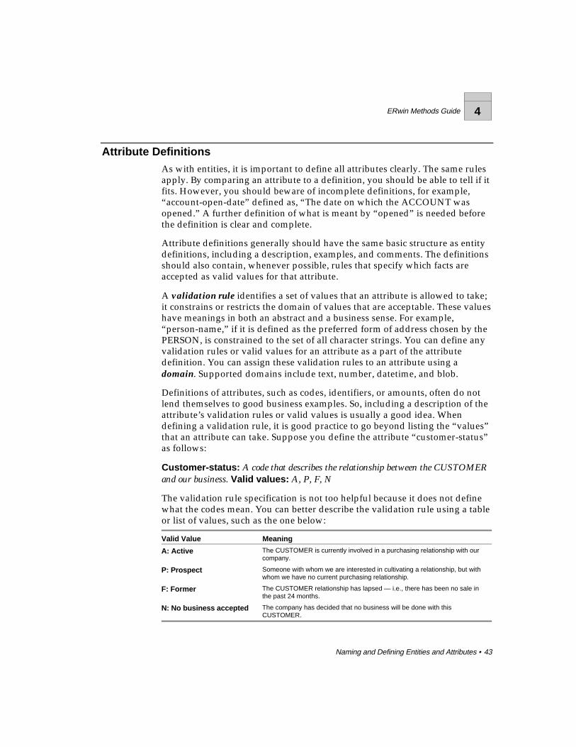
Definitions of attributes, such as codes, identifiers, or amounts, often do notlend themselves to good business examples. So, including a description of theattribute’s validation rules or valid values is usually a good idea. Whendefining a validation rule, it is good practice to go beyond listing the “values”that an attribute can take. Suppose you define the attribute “customer-status”as follows:
Customer-status: A code that describes the relationship between the CUSTOMERand our business. Valid values: A, P, F, N
The validation rule specification is not too helpful because it does not definewhat the codes mean. You can better describe the validation rule using a tableor list of values, such as the one below:
Valid Value Meaning
A: Active The CUSTOMER is currently involved in a purchasing relationship with ourcompany.
P: Prospect Someone with whom we are interested in cultivating a relationship, but withwhom we have no current purchasing relationship.
F: Former The CUSTOMER relationship has lapsed — i.e., there has been no sale inthe past 24 months.
N: No business accepted The company has decided that no business will be done with thisCUSTOMER.
4 ERwin Methods Guide
44 • Naming and Defining Entities and Attributes
RolenamesWhen a foreign key is contributed to a child entity through a relationship, youmay need to write a new or enhanced definition for the foreign key attributesthat explains their usage in the child entity. This is certainly the case when thesame attribute is contributed to the same entity more than once. Theseduplicated attributes may appear to be identical, but because they serve twodifferent purposes, they cannot have the same definition.
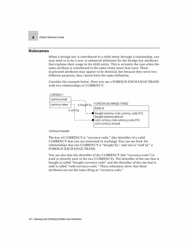
Consider the example below. Here you see a FOREIGN-EXCHANGE-TRADEwith two relationships to CURRENCY.
Currency Example
The key of CURRENCY is “currency-code,” (the identifier of a validCURRENCY that you are interested in tracking). You can see from therelationships that one CURRENCY is “bought by,” and one is “sold by” aFOREIGN-EXCHANGE-TRADE.
You see also that the identifier of the CURRENCY (the “currency-code”) isused to identify each of the two CURRENCYs. The identifier of the one that isbought is called “bought-currency-code” and the identifier of the one that issold is called “sold-currency-code.” These rolenames show that theseattributes are not the same thing as “currency-code.”
ERwin Methods Guide 4
Naming and Defining Entities and Attributes • 45
It would be somewhat silly to trade a CURRENCY for the same CURRENCYat the same time and exchange rate. Thus, for a given transaction (instance ofFOREIGN-EXCHANGE-TRADE) “bought-currency-code” and “sold-currency-code” must be different. By giving different definitions to the tworolenames, you can capture the difference between the two currency codes.
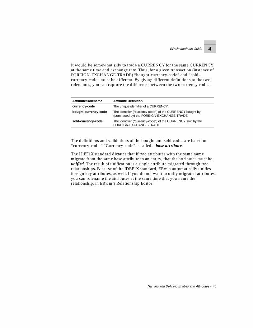
Attribute/Rolename Attribute Definition
currency-code The unique identifier of a CURRENCY.
bought-currency-code The identifier (“currency-code”) of the CURRENCY bought by(purchased by) the FOREIGN-EXCHANGE-TRADE.
sold-currency-code The identifier (“currency-code”) of the CURRENCY sold by theFOREIGN-EXCHANGE-TRADE.
The definitions and validations of the bought and sold codes are based on“currency-code.” “Currency-code” is called a base attribute.
The IDEF1X standard dictates that if two attributes with the same namemigrate from the same base attribute to an entity, that the attributes must beunified. The result of unification is a single attribute migrated through tworelationships. Because of the IDEF1X standard, ERwin automatically unifiesforeign key attributes, as well. If you do not want to unify migrated attributes,you can rolename the attributes at the same time that you name therelationship, in ERwin’s Relationship Editor.
4 ERwin Methods Guide
46 • Naming and Defining Entities and Attributes
Definitions and Business RulesBusiness rules have been mentioned earlier as an integral part of the datamodel. These rules take the form of relationships, rolenames, candidate keys,defaults, and other modeling structures not yet explored, includinggeneralization categories, referential integrity, and cardinality. And, businessrules are also captured in entity and attribute definitions and validation rules.
For example, the CURRENCY entity in the previous figure could be definedeither as the set of all valid currencies recognized anywhere in the world, orcould be defined as the subset of these which our company has decided to usein its day to day business operations. This is a subtle, but importantdistinction. In the latter case, there is a business rule, or “policy statement,”involved.
This rule manifests itself in the validation rules for “currency-code.” Itrestricts the valid values for “currency-code” to those that are used by thebusiness. Maintenance of the business rule becomes a task of maintaining thetable of valid values for CURRENCY. To permit or prohibit trading ofCURRENCYs, you simply create or delete instances in the table of validvalues.
The attributes “bought-currency-code” and “sold-currency-code” aresimilarly restricted. Both are further restricted by a validation rule that says“bought-currency-code” and “sold-currency-code” cannot be equal.Therefore, each is dependent on the value of the other in its actual use. UsingERwin, validation rules can be addressed in the definitions of attributes, andcan also be defined explicitly using validation rules, default values, and validvalue lists.
ERwin Methods Guide 5
Refining Model Relationships • 47
Refining Model Relationships
What’s in This Chapter?Relationships are a bit more complex than they might seem at first. They carrya lot of information. Some might say that they are the heart of the data model,because, to a great extent, they describe the rules of the business and theconstraints on creating, modifying, and deleting instances.
For example, you can use cardinality to define exactly how many instancesare involved in both the child and parent entities in the relationship. And youcan further specify how you want to handle database actions such as INSERT,UPDATE, and DELETE using referential integrity rules.
Data modeling also supports highly complex relationship types that enableyou to construct a logical model of your data that is understandable to both“business” and “systems” experts.
5 ERwin Methods Guide
48 • Refining Model Relationships
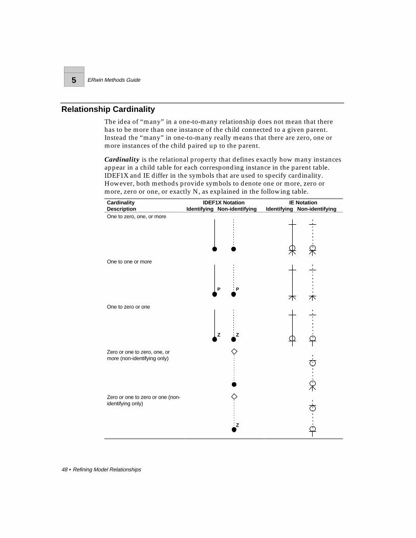
Relationship CardinalityThe idea of “many” in a one-to-many relationship does not mean that therehas to be more than one instance of the child connected to a given parent.Instead the “many” in one-to-many really means that there are zero, one ormore instances of the child paired up to the parent.
Cardinality is the relational property that defines exactly how many instancesappear in a child table for each corresponding instance in the parent table.IDEF1X and IE differ in the symbols that are used to specify cardinality.However, both methods provide symbols to denote one or more, zero ormore, zero or one, or exactly N, as explained in the following table.
CardinalityDescription
IDEF1X NotationIdentifying Non-identifying
IE NotationIdentifying Non-identifying
One to zero, one, or more
One to one or more
P P
One to zero or one
Z Z
Zero or one to zero, one, ormore (non-identifying only)
Zero or one to zero or one (non-identifying only)
Z

ERwin Methods Guide 5
Refining Model Relationships • 49
Cardinality lets you specify additional business rules that apply to therelationship. In the example below, the business has decided to identify eachMOVIE COPY based on both the foreign key “movie-number” and asurrogate key “copy-number.” Further, each MOVIE is available as one ormore MOVIE COPYs. The business has also stated that the relationship isidentifying, that MOVIE COPY cannot exist unless there is a correspondingMOVIE.
Cardinality in a One-to-Many Identifying Relationship
The MOVIE-MOVIE COPY model also specifies the cardinality for therelationship. The relationship line shows that there will be exactly oneMOVIE, and only one, participating in a relationship. This is because MOVIEis the parent in the relationship.
By making MOVIE-COPY the child in the relationship (shown with a dot inIDEF1X), the business defined a MOVIE-COPY as one of perhaps severalrentable copies of a movie title. The business also determined that to beincluded in the database, a MOVIE must have at least one MOVIE-COPY.This makes the cardinality of the “is available as” relationship one-to-one ormore. The “P” symbol next to the dot represents cardinality of “one or more.”As a result, you also know that a MOVIE with no copies is not a legitimateinstance in this database.
In contrast, the business might want to know about all of the MOVIEs in theworld, even those for which they have no copies. So their business rule is thatfor a MOVIE to exist (be recorded in their information system) there can bezero, one, or more copies. To record this business rule, the “P” is removed.When cardinality is not explicitly indicated in the diagram, cardinality is one-to-zero, one or more.
Cardinality in Non-Identifying RelationshipsNon-identifying relationships contribute keys from a parent to a child entity.But, by definition, some (or all) of the keys do not become part of the key ofthe child. This means that the child will not be identification-dependent on theparent. And there can be situations where an entity at the “many” end of therelationship can exist without a “parent,” that is, it is not existence-dependent.
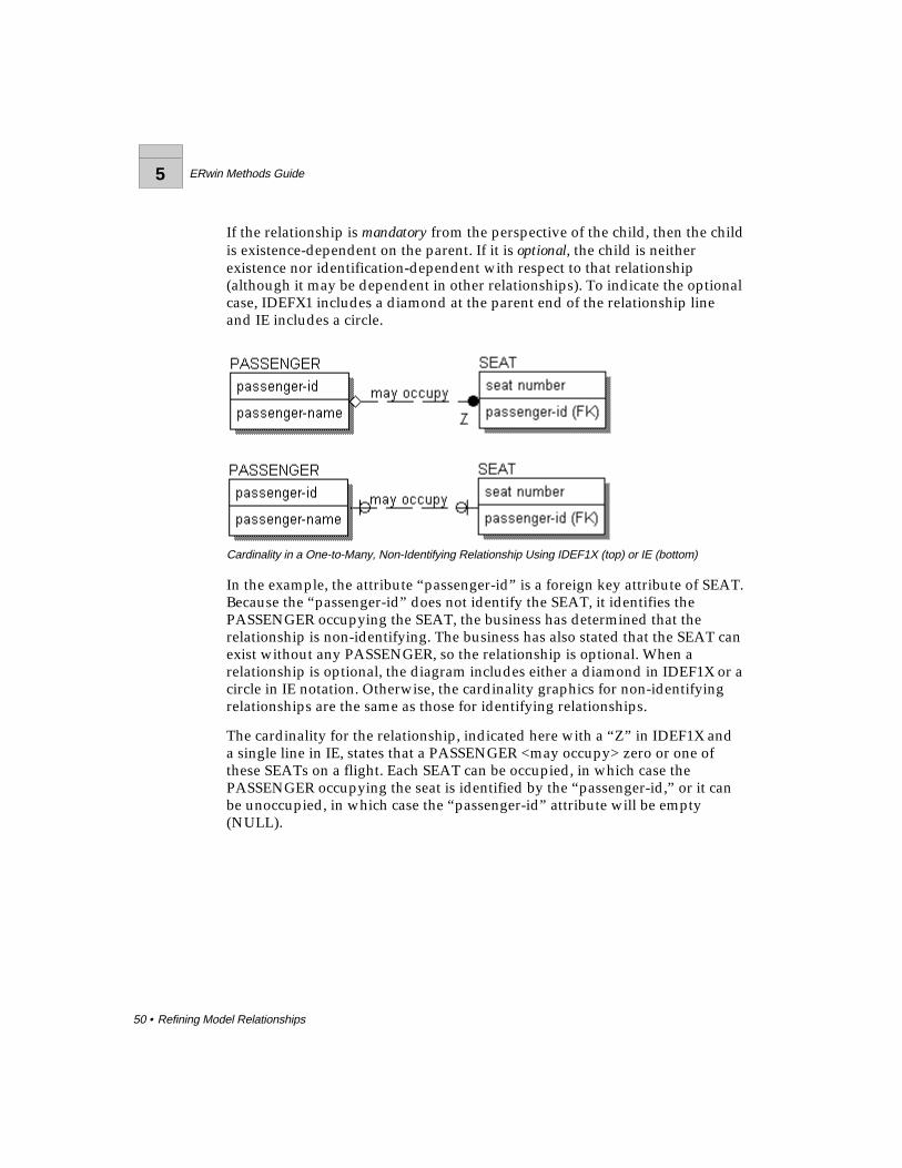
5 ERwin Methods Guide
50 • Refining Model Relationships
If the relationship is mandatory from the perspective of the child, then the childis existence-dependent on the parent. If it is optional, the child is neitherexistence nor identification-dependent with respect to that relationship(although it may be dependent in other relationships). To indicate the optionalcase, IDEFX1 includes a diamond at the parent end of the relationship lineand IE includes a circle.
Cardinality in a One-to-Many, Non-Identifying Relationship Using IDEF1X (top) or IE (bottom)
In the example, the attribute “passenger-id” is a foreign key attribute of SEAT.Because the “passenger-id” does not identify the SEAT, it identifies thePASSENGER occupying the SEAT, the business has determined that therelationship is non-identifying. The business has also stated that the SEAT canexist without any PASSENGER, so the relationship is optional. When arelationship is optional, the diagram includes either a diamond in IDEF1X or acircle in IE notation. Otherwise, the cardinality graphics for non-identifyingrelationships are the same as those for identifying relationships.
The cardinality for the relationship, indicated here with a “Z” in IDEF1X anda single line in IE, states that a PASSENGER <may occupy> zero or one ofthese SEATs on a flight. Each SEAT can be occupied, in which case thePASSENGER occupying the seat is identified by the “passenger-id,” or it canbe unoccupied, in which case the “passenger-id” attribute will be empty(NULL).
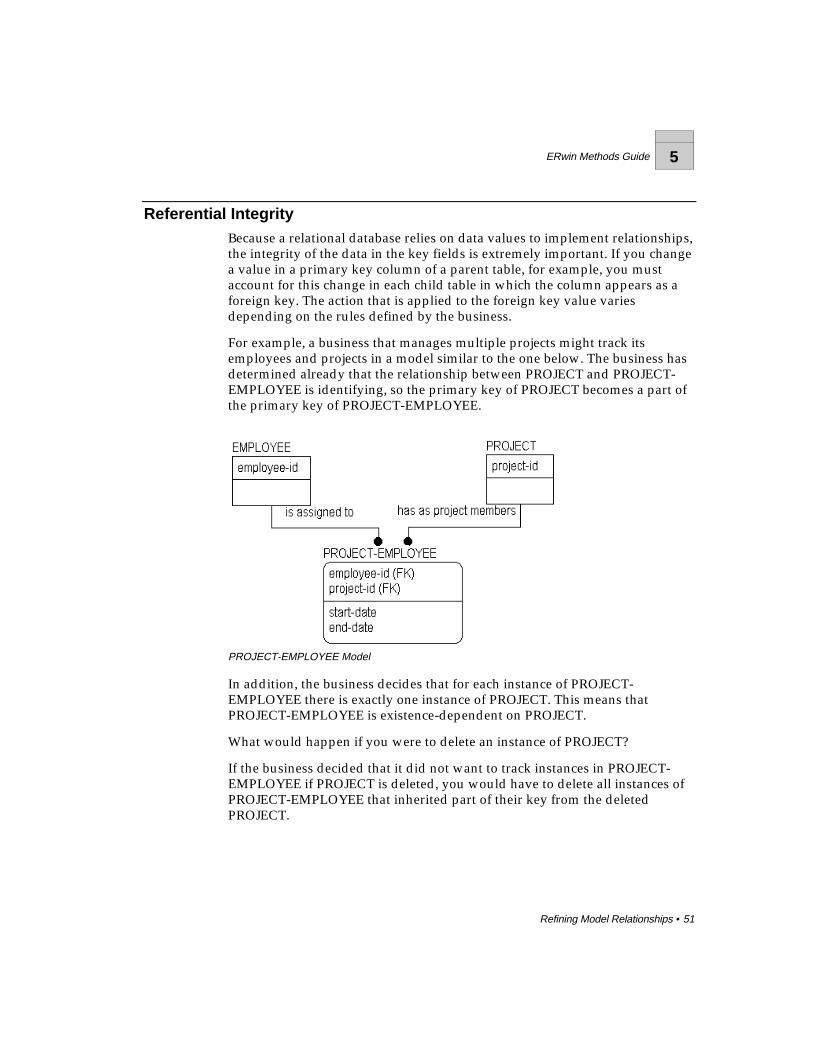
ERwin Methods Guide 5
Refining Model Relationships • 51
Referential IntegrityBecause a relational database relies on data values to implement relationships,the integrity of the data in the key fields is extremely important. If you changea value in a primary key column of a parent table, for example, you mustaccount for this change in each child table in which the column appears as aforeign key. The action that is applied to the foreign key value variesdepending on the rules defined by the business.
For example, a business that manages multiple projects might track itsemployees and projects in a model similar to the one below. The business hasdetermined already that the relationship between PROJECT and PROJECT-EMPLOYEE is identifying, so the primary key of PROJECT becomes a part ofthe primary key of PROJECT-EMPLOYEE.
PROJECT-EMPLOYEE Model
In addition, the business decides that for each instance of PROJECT-EMPLOYEE there is exactly one instance of PROJECT. This means thatPROJECT-EMPLOYEE is existence-dependent on PROJECT.
What would happen if you were to delete an instance of PROJECT?
If the business decided that it did not want to track instances in PROJECT-EMPLOYEE if PROJECT is deleted, you would have to delete all instances ofPROJECT-EMPLOYEE that inherited part of their key from the deletedPROJECT.
5 ERwin Methods Guide
52 • Refining Model Relationships
The rule that specifies the action taken when a parent key is deleted is calledreferential integrity. And the referential integrity option chosen for this actionin this relationship is cascade. Each time an instance of PROJECT is deleted,this delete cascades to the PROJECT-EMPLOYEE table and causes all relatedinstances in PROJECT-EMPLOYEE to be deleted, as well.
Available actions for referential integrity include not only cascade, but alsorestrict, set null, and set default. Each of the options is explained below:
♦ Cascade . Each time an instance in the parent entity is deleted, eachrelated instance in the child entity must also be deleted.
♦ Restrict . Deletion of an instance in the parent entity is prohibited if thereare one or more related instances in the child entity, or deletion of aninstance in the child entity is prohibited if there is a related instance in theparent entity.
♦ Set Null . Each time an instance in the parent entity is deleted, the foreignkey attribute(s) in each related instance in the child entity are set toNULL.
♦ Set Default . Each time an instance in the parent entity is deleted, theforeign key attribute(s) in each related instance in the child entity are setto the specified default value.
♦ <None> . No referential integrity action is required. Not every action musthave a referential integrity rule associated with it. For example, a businessmay decide that referential integrity is not required when deleting aninstance in a child entity. This is a valid business rule in cases where thecardinality is zero or one to zero, one or more, because instances in thechild entity can exist even if there are no related instances in the parententity.
Although referential integrity is not a formal part of the IDEF1X or IElanguages, it does capture business rules that indicate how the completeddatabase should work, so it is a critical part of data modeling. Because of this,ERwin provides a method for both capture and display of referential integrityrules.
Once referential integrity is defined, the facilitator or analyst should test thereferential integrity rules defined by the business users by asking questions orworking through different scenarios that show the results of the businessdecision. When the requirements are defined and fully understood, thefacilitator or analyst can recommend specific referential integrity actions, likerestrict or cascade.
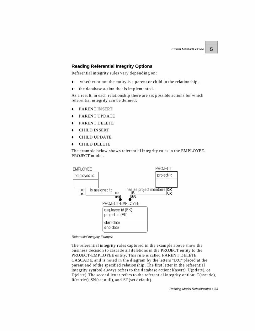
ERwin Methods Guide 5
Refining Model Relationships • 53
Reading Referential Integrity OptionsReferential integrity rules vary depending on:
♦ whether or not the entity is a parent or child in the relationship.
♦ the database action that is implemented.
As a result, in each relationship there are six possible actions for whichreferential integrity can be defined:
♦ PARENT INSERT
♦ PARENT UPDATE
♦ PARENT DELETE
♦ CHILD INSERT
♦ CHILD UPDATE
♦ CHILD DELETE
The example below shows referential integrity rules in the EMPLOYEE-PROJECT model.
Referential Integrity Example
The referential integrity rules captured in the example above show thebusiness decision to cascade all deletions in the PROJECT entity to thePROJECT-EMPLOYEE entity. This rule is called PARENT DELETECASCADE, and is noted in the diagram by the letters "D:C" placed at theparent end of the specified relationship. The first letter in the referentialintegrity symbol always refers to the database action: I(nsert), U(pdate), orD(elete). The second letter refers to the referential integrity option: C(ascade),R(estrict), SN(set null), and SD(set default).

5 ERwin Methods Guide
54 • Refining Model Relationships
In the example above, no referential integrity option has been specified forPARENT INSERT, so referential integrity for insert (I:) is not displayed on thediagram.
RI, Cardinality, and Identifying RelationshipsIn the example above, the relationship between PROJECT and PROJECT-EMPLOYEE is identifying. So the valid options for referential integrity for theparent entity in the relationship, PROJECT, include cascade and restrict.
Cascade indicates that all instances of PROJECT-EMPLOYEE that are affectedby the deletion of an instance of PROJECT should also be deleted. Restrictindicates that a PROJECT cannot be deleted until all instances of PROJECT-EMPLOYEE that have inherited its key have been deleted. If there are any left,the delete is “restricted.”
Why would you want to restrict the deletion? One reason might be that thebusiness needs to know other facts about a PROJECT-EMPLOYEE such as the“date started” on the project. If you cascade the delete, you lose thissupplementary information.
In the case of updating an instance in the parent entity, the business has alsodetermined that the updated information should cascade to the relatedinstances in the child entity.
As you can see in the example, different rules apply when an instance isinserted, updated, or deleted in the child entity. When an instance is inserted,for example, the action is set to restrict. This rule appears in as "I:R" placednext to the child entity in the relationship. This means that an instance can beadded to the child entity only if the referenced foreign key matches an existinginstance in the parent entity. So, you can insert a new instance in PROJECT-EMPLOYEE only if the value in the key field matches a key value in thePROJECT entity.

ERwin Methods Guide 5
Refining Model Relationships • 55
RI, Cardinality, and Non-Identifying RelationshipsIf the business decides that PROJECT-EMPLOYEEs are not existence oridentification-dependent on PROJECT, you can change the relationshipbetween PROJECT and PROJECT-EMPLOYEE to optional, non-identifying. Inthis type of relationship, the referential integrity options are very different.
Referential Integrity for a Non-Identifying Relationship
Because a foreign key contributed across a non-identifying relationship isallowed to be NULL, one of the referential integrity options you could specifyfor PARENT DELETE is "set null." Set null indicates that if an instance ofPROJECT is deleted, then any foreign key inherited from PROJECT in arelated instance in PROJECT-EMPLOYEE should be set to NULL. The deletedoes not cascade as in our previous example, and it is not prohibited (as inrestrict). The advantage of this approach is that you can preserve theinformation about the PROJECT-EMPLOYEE while effectively breaking theconnection between the PROJECT-EMPLOYEE and PROJECT.
Decisions to use cascade or set null reflect business decisions aboutmaintaining the “historical” knowledge of relationships represented by theforeign keys.

5 ERwin Methods Guide
56 • Refining Model Relationships
Additional Relationship TypesRelationships define whether the child entity is dependent or independent ofthe parent entity and how many instances are related in parent and childentities. As you develop a logical model, you may find relationships that donot fall into the standard, one-to-many relationships discussed in previouschapters. These relationships include:
♦ Many-to-many relationships. A relationship where one entity <owns>many instances of a second entity, and the second entity also <owns>many instances of the first entity. For example, an EMPLOYEE <has> oneor more JOB TITLEs, and a JOB TITLE <is applied to> one or moreEMPLOYEEs.
♦ N-ary relationships . A simple one-to-many relationship between twoentities is termed binary. When a one-to-many relationship exists betweentwo or more parents and a single child entity, it is termed an n-aryrelationship.
♦ Recursive relationships. Entities that have a relationship to themselvestake part in recursive relationships. For example, for the EMPLOYEEentity, you could include a relationship to show that one EMPLOYEE<manages> one or more EMPLOYEEs. This type of relationship is alsoused for bill-of-materials structures, to show relationships between parts.
♦ Subtype relationships . Related entities are grouped together so that allcommon attributes appear in a single entity, but all attributes that are notin-common appear in separate, related entities. For example, theEMPLOYEE entity could be subtyped into FULL-TIME and PART-TIME.
Each of these relationship types is discussed more fully later in this chapter.

ERwin Methods Guide 5
Refining Model Relationships • 57
Many-to-Many RelationshipsIn key-based and fully-attributed models, relationships must relate zero orone instances in a parent entity to a specific set of instances in a child entity.As a result of this rule, many-to-many relationships that were discovered anddocumented in an ERD or earlier modeling phase must be broken down into apair of one-to-many relationships.
The example above shows a many-to-many relationship between STUDENTsand COURSEs. If you did not eliminate the many-to-many relationshipbetween COURSE and STUDENT, for example, the key of COURSE would beincluded in the key of STUDENT, and vice versa. But COURSEs are identifiedby their own keys, and likewise for STUDENTs; creating an endless loop!

5 ERwin Methods Guide
58 • Refining Model Relationships
You can eliminate the many-to-many relationship by creating an associativeentity. In the example below, the many-to-many relationship betweenSTUDENT and COURSE is resolved by adding the COURSE-ROSTER entity.
Resolving the STUDENT-COURSE Relationship Using an Associative Entity
COURSE-ROSTER is an associative entity, meaning it is used to define theassociation between two related entities.
Many-to-many relationships often hide meaning. In the diagram with a many-to-many relationship, you know that a STUDENT enrolls in many COURSEs,but no information is included to show how. When you resolve the many-to-many relationship, you see not only how the entities are related, but uncoveradditional information, such as the “course-time,” which also describes factsabout the relationship.
Once the many-to-many relationship is resolved, you are faced with therequirement to include relationship verb phrases that validate the structure.There are two ways to do this: construct new verb phrases or use the verbphrases as they existed for the many-to-many relationship. The moststraightforward way is to continue to read the “many-to-many” relationship,through the associative entity. So you can read A STUDENT <enrolls in>many COURSEs and A COURSE <is taken by> many STUDENTs. Manymodelers adopt this style for constructing and reading a model.
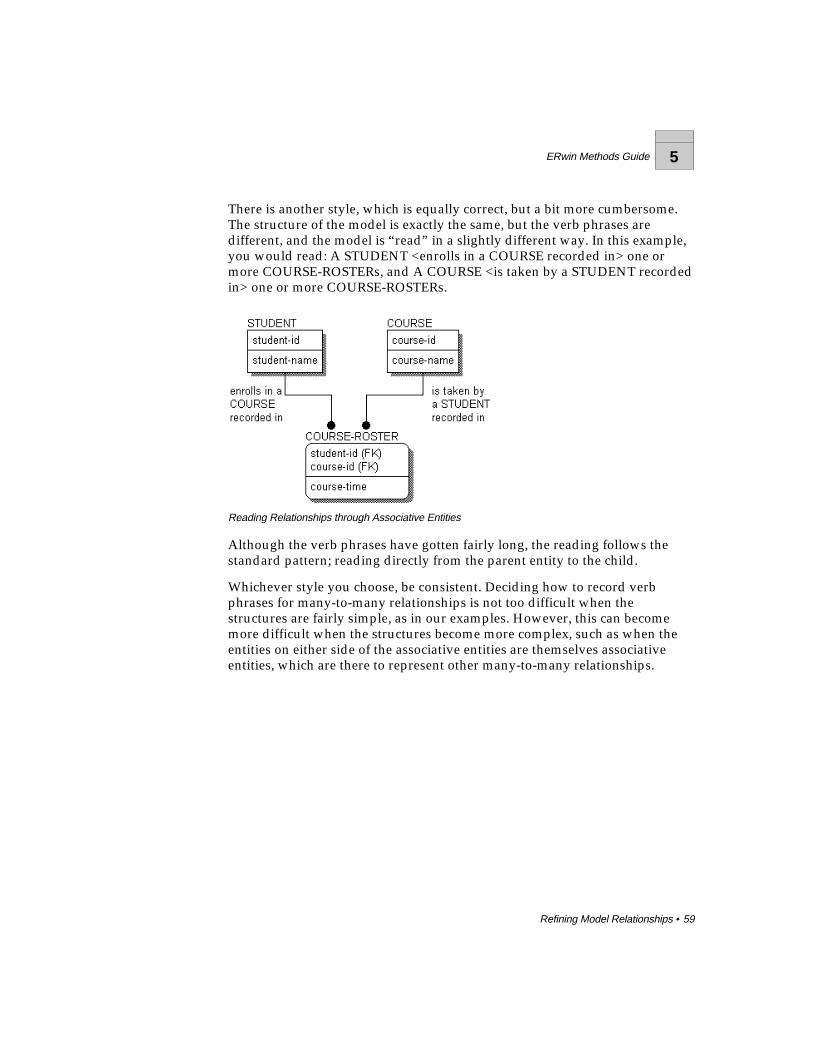
ERwin Methods Guide 5
Refining Model Relationships • 59
There is another style, which is equally correct, but a bit more cumbersome.The structure of the model is exactly the same, but the verb phrases aredifferent, and the model is “read” in a slightly different way. In this example,you would read: A STUDENT <enrolls in a COURSE recorded in> one ormore COURSE-ROSTERs, and A COURSE <is taken by a STUDENT recordedin> one or more COURSE-ROSTERs.
Reading Relationships through Associative Entities
Although the verb phrases have gotten fairly long, the reading follows thestandard pattern; reading directly from the parent entity to the child.
Whichever style you choose, be consistent. Deciding how to record verbphrases for many-to-many relationships is not too difficult when thestructures are fairly simple, as in our examples. However, this can becomemore difficult when the structures become more complex, such as when theentities on either side of the associative entities are themselves associativeentities, which are there to represent other many-to-many relationships.
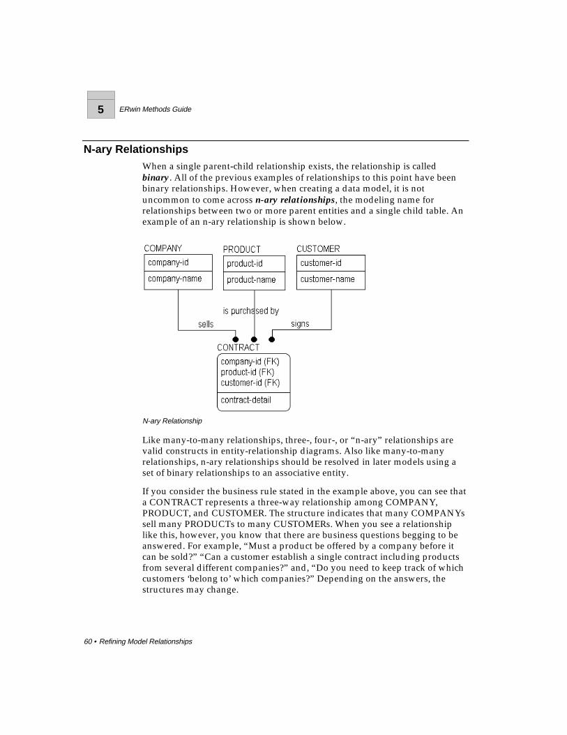
5 ERwin Methods Guide
60 • Refining Model Relationships
N-ary RelationshipsWhen a single parent-child relationship exists, the relationship is calledbinary. All of the previous examples of relationships to this point have beenbinary relationships. However, when creating a data model, it is notuncommon to come across n-ary relationships, the modeling name forrelationships between two or more parent entities and a single child table. Anexample of an n-ary relationship is shown below.
N-ary Relationship
Like many-to-many relationships, three-, four-, or “n-ary” relationships arevalid constructs in entity-relationship diagrams. Also like many-to-manyrelationships, n-ary relationships should be resolved in later models using aset of binary relationships to an associative entity.
If you consider the business rule stated in the example above, you can see thata CONTRACT represents a three-way relationship among COMPANY,PRODUCT, and CUSTOMER. The structure indicates that many COMPANYssell many PRODUCTs to many CUSTOMERs. When you see a relationshiplike this, however, you know that there are business questions begging to beanswered. For example, “Must a product be offered by a company before itcan be sold?” “Can a customer establish a single contract including productsfrom several different companies?” and, “Do you need to keep track of whichcustomers ‘belong to’ which companies?” Depending on the answers, thestructures may change.

ERwin Methods Guide 5
Refining Model Relationships • 61
If, for example, the answer to the question "Must a product be offered by acompany before it can be sold?” is “yes,” then you would have to change thestructure as shown below.
Resolving an N-ary Relationship
Because PRODUCTs must be offered by COMPANYs, you can create anassociative entity to capture this relationship. As a result, the original “three-way” relationship to CONTRACT is replaced by two, “two-way”relationships.
By asking a variety of business questions, it is likely that you will find thatmost “n-ary” relationships can be broken down into a series of relationshipsto associative entities.
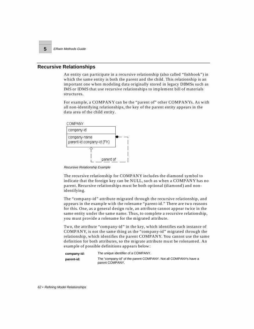
5 ERwin Methods Guide
62 • Refining Model Relationships
Recursive RelationshipsAn entity can participate in a recursive relationship (also called “fishhook”) inwhich the same entity is both the parent and the child. This relationship is animportant one when modeling data originally stored in legacy DBMSs such asIMS or IDMS that use recursive relationships to implement bill of materialsstructures.
For example, a COMPANY can be the “parent of” other COMPANYs. As withall non-identifying relationships, the key of the parent entity appears in thedata area of the child entity.
Recursive Relationship Example
The recursive relationship for COMPANY includes the diamond symbol toindicate that the foreign key can be NULL, such as when a COMPANY has noparent. Recursive relationships must be both optional (diamond) and non-identifying.
The “company-id” attribute migrated through the recursive relationship, andappears in the example with the rolename “parent-id.” There are two reasonsfor this. One, as a general design rule, an attribute cannot appear twice in thesame entity under the same name. Thus, to complete a recursive relationship,you must provide a rolename for the migrated attribute.
Two, the attribute “company-id” in the key, which identifies each instance ofCOMPANY, is not the same thing as the “company-id” migrated through therelationship, which identifies the parent COMPANY. You cannot use the samedefinition for both attributes, so the migrate attribute must be rolenamed. Anexample of possible definitions appears below:
company-id: The unique identifier of a COMPANY.
parent-id: The “company-id” of the parent COMPANY. Not all COMPANYs have aparent COMPANY.
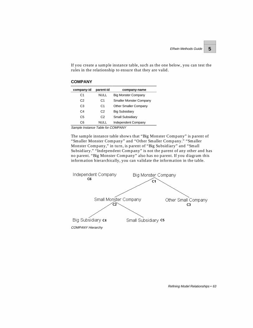
ERwin Methods Guide 5
Refining Model Relationships • 63
If you create a sample instance table, such as the one below, you can test therules in the relationship to ensure that they are valid.
COMPANY
company-id parent-id company-name
C1 NULL Big Monster Company
C2 C1 Smaller Monster Company
C3 C1 Other Smaller Company
C4 C2 Big Subsidiary
C5 C2 Small Subsidiary
C6 NULL Independent Company
Sample Instance Table for COMPANY
The sample instance table shows that “Big Monster Company” is parent of“Smaller Monster Company” and “Other Smaller Company.” “SmallerMonster Company,” in turn, is parent of “Big Subsidiary” and “SmallSubsidiary.” “Independent Company” is not the parent of any other and hasno parent. “Big Monster Company” also has no parent. If you diagram thisinformation hierarchically, you can validate the information in the table.
COMPANY Hierarchy
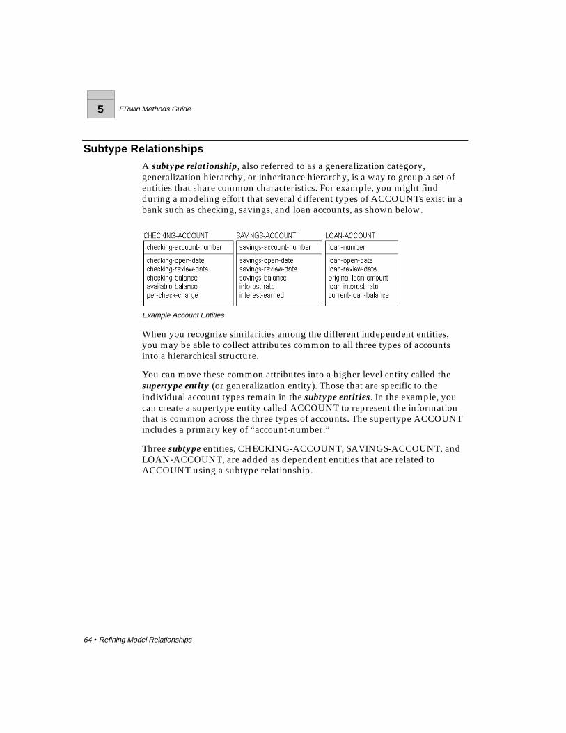
5 ERwin Methods Guide
64 • Refining Model Relationships
Subtype Relationships
A subtype relationship, also referred to as a generalization category,generalization hierarchy, or inheritance hierarchy, is a way to group a set ofentities that share common characteristics. For example, you might findduring a modeling effort that several different types of ACCOUNTs exist in abank such as checking, savings, and loan accounts, as shown below.
Example Account Entities
When you recognize similarities among the different independent entities,you may be able to collect attributes common to all three types of accountsinto a hierarchical structure.
You can move these common attributes into a higher level entity called thesupertype entity (or generalization entity). Those that are specific to theindividual account types remain in the subtype entities. In the example, youcan create a supertype entity called ACCOUNT to represent the informationthat is common across the three types of accounts. The supertype ACCOUNTincludes a primary key of “account-number.”
Three subtype entities, CHECKING-ACCOUNT, SAVINGS-ACCOUNT, andLOAN-ACCOUNT, are added as dependent entities that are related toACCOUNT using a subtype relationship.
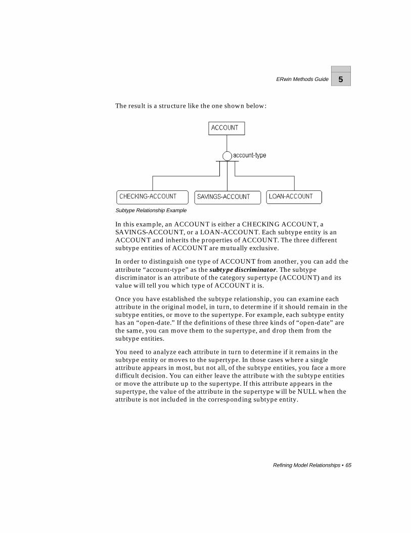
ERwin Methods Guide 5
Refining Model Relationships • 65
The result is a structure like the one shown below:
Subtype Relationship Example
In this example, an ACCOUNT is either a CHECKING ACCOUNT, aSAVINGS-ACCOUNT, or a LOAN-ACCOUNT. Each subtype entity is anACCOUNT and inherits the properties of ACCOUNT. The three differentsubtype entities of ACCOUNT are mutually exclusive.
In order to distinguish one type of ACCOUNT from another, you can add theattribute “account-type” as the subtype discriminator. The subtypediscriminator is an attribute of the category supertype (ACCOUNT) and itsvalue will tell you which type of ACCOUNT it is.
Once you have established the subtype relationship, you can examine eachattribute in the original model, in turn, to determine if it should remain in thesubtype entities, or move to the supertype. For example, each subtype entityhas an “open-date.” If the definitions of these three kinds of “open-date” arethe same, you can move them to the supertype, and drop them from thesubtype entities.
You need to analyze each attribute in turn to determine if it remains in thesubtype entity or moves to the supertype. In those cases where a singleattribute appears in most, but not all, of the subtype entities, you face a moredifficult decision. You can either leave the attribute with the subtype entitiesor move the attribute up to the supertype. If this attribute appears in thesupertype, the value of the attribute in the supertype will be NULL when theattribute is not included in the corresponding subtype entity.

5 ERwin Methods Guide
66 • Refining Model Relationships
Which alternative to choose depends on how many of the subtype entitiesshare the common attribute. If most do, it is good practice, at higher levelmodels, to move them up. If few subtype entities share the attribute, it is bestto leave them where they are. In lower level models, depending on thepurpose, it is often appropriate to leave the attributes in their subtype entity.
After analysis, the resulting model might appear like the one below.
Account Subtype Example
When developing a subtype relationship, you must also be aware of anyspecific business rules that need to be imposed at the subtype level that arenot pertinent to other subtypes of the supertype. For example, LOANaccounts are deleted after they reach a zero balance. You would hardly like todelete CHECKING and SAVINGS accounts under the same conditions.
There may also be relationships that are meaningful to a single subtype andnot to any other subtype in the hierarchy. The LOAN entity needs to beexamined, for example, to ensure that any previous relationships to records ofcustomer payments or assets are not lost because of a different organizationalstructure.

ERwin Methods Guide 5
Refining Model Relationships • 67
Complete Versus Incomplete Subtype StructuresIn IDEF1X, different symbols are used to specify whether or not the set ofsubtype entities in a subtype relationship is fully defined. An incompletesubtype indicates that the modeler feels there may be other subtype entitiesthat have not yet been discovered. An incomplete subtype is indicated by asingle line at the bottom of the subtype symbol.
Incomplete Subtype
A complete subtype indicates that the modeler is certain that all possiblesubtype entities are included in the subtype structure. For example, acomplete subtype could capture information specific to male and femaleemployees, as shown below. A complete subtype is indicated by two lines atthe bottom of the subtype symbol.
Complete Subtype
5 ERwin Methods Guide
68 • Refining Model Relationships
When you create a subtype relationship, it is a good rule of thumb to alsocreate a validation rule for the discriminator. This helps to ensure that allsubtypes have been discovered. For example, a validation rule for “account-type” might include: C=checking account, S=savings account, L=loans. If thebusiness also has legacy data with account types of “O,” the validation ruleuncovers the undocumented type and lets you decide if the “O” is a symptomof poor design in the legacy system or a real account type that you forgot.
Inclusive and Exclusive RelationshipsUnlike IDEF1X, IE notation does not distinguish between complete andincomplete subtype relationships. Instead, IE notation documents whether therelationship is exclusive or inclusive.
In an exclusive subtype relationship, each instance in the supertype can relateto one and only one subtype. For example, you might model a business rulethat says an employee can be either a full-time or part-time employee but notboth. To create the model, you would include an EMPLOYEE supertypeentity with FULL-TIME and PART-TIME subtype entities and a discriminatorattribute called “employee-status.” In addition, you would constrain the valueof the discriminator to show that valid values for it include “F” to denote full-time and “P” to denote part-time.
In an inclusive subtype relationship, each instance in the supertype can relateto one or more subtypes. In our example, the business rule might now statethat an employee could be full-time, part-time, or both. In this example, youwould constrain the value of the discriminator to show that valid values for itinclude “F” to denote full-time, “P” to denote part-time, and “B” to denoteboth full-time and part-time.
Note : In IDEF1X notation, you can represent inclusive subtypes by drawing a separaterelationship between the supertype entity and each subtype entity.
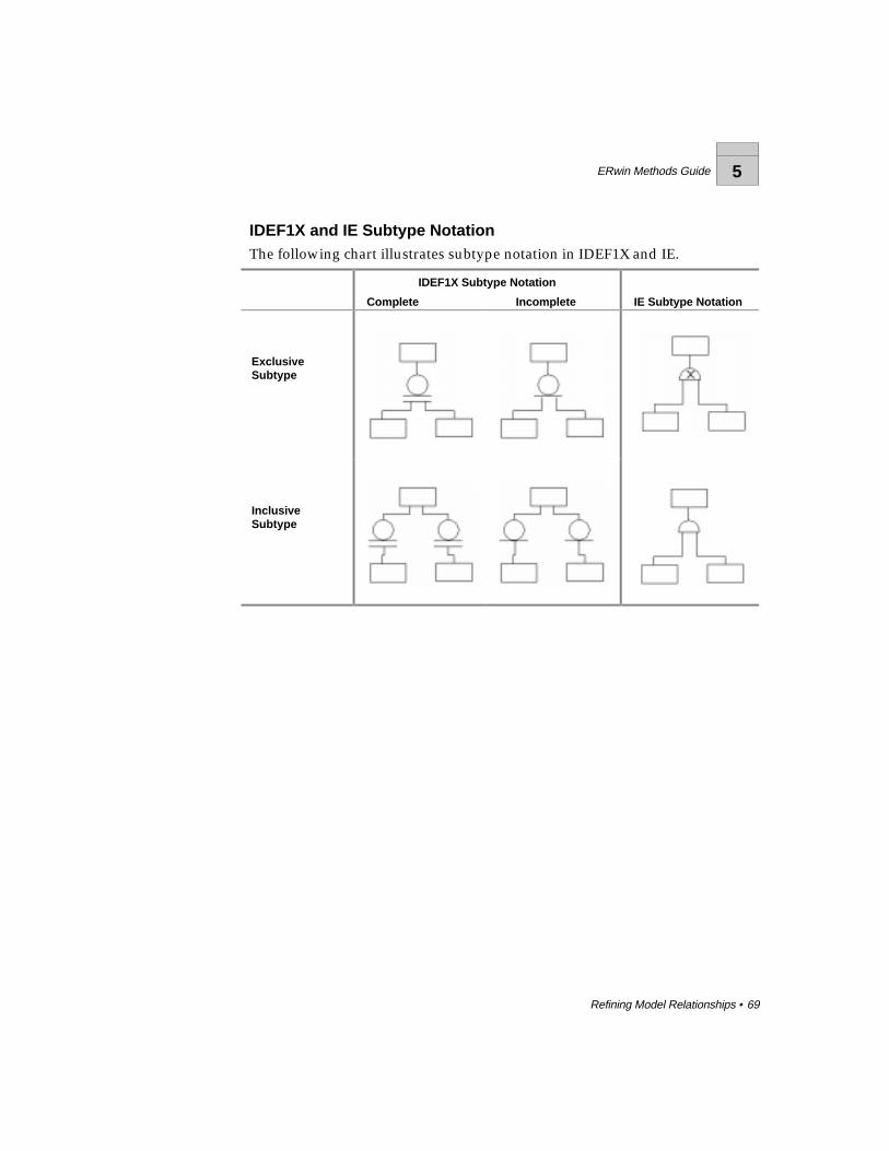
ERwin Methods Guide 5
Refining Model Relationships • 69
IDEF1X and IE Subtype NotationThe following chart illustrates subtype notation in IDEF1X and IE.
IDEF1X Subtype Notation
Complete Incomplete IE Subtype Notation
ExclusiveSubtype
InclusiveSubtype
5 ERwin Methods Guide
70 • Refining Model Relationships
When to Create a Subtype RelationshipTo summarize, there are three reasons to create a subtype relationship:
♦ First, the entities share a common set of attributes. This was the case inour examples above.
♦ Second, the entities share a common set of relationships. This has not beenexplored but, referring back to the account structure, you could, asneeded, collect any common relationships that the subtype entities hadinto a single relationship from the generic parent. For example, if eachaccount type is related to many CUSTOMERs, you can include a singlerelationship at the ACCOUNT level, and eliminate the separaterelationships from the individual subtype entities.
♦ Third, subtype entities should be exposed in a model if the businessdemands it (usually for communication or understanding purposes) evenif the subtype entities have no attributes that are different, and even ifthey participate in no relationships distinct from other subtype entities.Remember that one of the major purposes of a model is to assist incommunication of information structures, and if showing subtype entitiesassists communication, then show them.

ERwin Methods Guide 6
Normalization • 71
Normalization
IntroductionNormalization is the process of making a database design comply with thedesign rules outlined by E. F. Codd for relational databases. Following therules for normalization, you can control and eliminate data redundancy byremoving all model structures that provide multiple ways to know the samefact.
The goal of normalization is to ensure that there is only one way to know a“fact.” A useful slogan summarizing this goal is:
ONE FACT IN ONE PLACE!
To provide a basic understanding of the principles of normalization, thischapter includes a variety of examples of common design problems andnormalization solutions.
6 ERwin Methods Guide
72 • Normalization
Overview of the Normal FormsThe following are formal definitions for the most common normal forms.
Functional Dependence (FD)Given an entity E, attribute B of E is functionally dependent on attribute A ofE if and only if each value of A in E has associated with it precisely one valueof B in E (at any one time). In other words, A uniquely determines B.
Full Functional DependenceGiven an entity E, an attribute B of E is fully functionally dependent on a setof attributes A of E if and only if B is functionally dependent on A and notfunctionally dependent on any proper subset of A.
First Normal Form (1NF)An entity E is in 1NF if and only if all underlying values contain atomic valuesonly. Any repeating groups (that might be found in legacy COBOL datastructures, for example) must be eliminated.
Second Normal Form (2NF)An entity E is in 2NF if it is in 1NF and every non-key attribute is fullydependent on the primary key. In other words, there are no partial keydependencies — dependence is on the entire key K of E and not on a propersubset of K.
Third Normal Form (3NF)An entity E is in 3NF if it is in 2NF and no non-key attribute of E is dependenton another non-key attribute. There are several equivalent ways to express3NF. Here is a second: An entity E is in 3NF if it is in 2NF and every non-keyattribute is non transitively dependent on the primary key. A third and finalway is: An entity E is in 3NF if every attribute in E carries a fact about all of E(2NF) and only about E (as represented by the entity’s entire key and only bythat key). One way to remember how to implement 3NF is using the followingquip: “Each attribute relies on the key, the whole key, and nothing but thekey, so help me Codd!”
Beyond 3NF lie three more normal forms, Boyce-Codd, Fourth and Fifth. Inpractice, third normal form is the standard. At the level of the physicaldatabase design, choices are usually made to “denormalize” a structure infavor of performance for a certain set of transactions. This may introduceredundancy in the structure, but is often worth it.
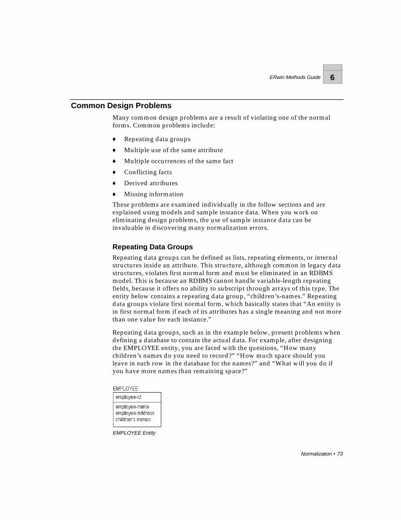
ERwin Methods Guide 6
Normalization • 73
Common Design ProblemsMany common design problems are a result of violating one of the normalforms. Common problems include:
♦ Repeating data groups
♦ Multiple use of the same attribute
♦ Multiple occurrences of the same fact
♦ Conflicting facts
♦ Derived attributes
♦ Missing information
These problems are examined individually in the follow sections and areexplained using models and sample instance data. When you work oneliminating design problems, the use of sample instance data can beinvaluable in discovering many normalization errors.
Repeating Data GroupsRepeating data groups can be defined as lists, repeating elements, or internalstructures inside an attribute. This structure, although common in legacy datastructures, violates first normal form and must be eliminated in an RDBMSmodel. This is because an RDBMS cannot handle variable-length repeatingfields, because it offers no ability to subscript through arrays of this type. Theentity below contains a repeating data group, “children’s-names.” Repeatingdata groups violate first normal form, which basically states that “An entity isin first normal form if each of its attributes has a single meaning and not morethan one value for each instance.”
Repeating data groups, such as in the example below, present problems whendefining a database to contain the actual data. For example, after designingthe EMPLOYEE entity, you are faced with the questions, “How manychildren’s names do you need to record?” “How much space should youleave in each row in the database for the names?” and “What will you do ifyou have more names than remaining space?”
EMPLOYEE Entity

6 ERwin Methods Guide
74 • Normalization
A sample instance table might clarify the problem:
EMPLOYEE
emp-id emp-name emp-address children's-names
E1 Tom Berkeley Jane
E2 Don Berkeley Tom, Dick, Donna
E3 Bob Princeton —
E4 John New York Lisa
E5 Carol Berkeley —
EMPLOYEE Sample Instance Table
In order to fix the design, it is necessary to somehow remove the list ofchildren’s names from the EMPLOYEE entity. One way to do this is to add aCHILD table to contain the information about employee’s children. Once thatis done, you can represent the names of the children as single entries in theCHILD table. In terms of the physical record structure for employee, this canresolve some of your questions about space allocation, and prevent wastingspace in the record structure for employees who have no children or,conversely, deciding how much space to allocate for employees with families.
EMPLOYEE
emp-id emp-name emp-address
E1 Tom Berkeley
E2 Don Berkeley
E3 Bob Princeton
E4 Carol Berkeley
CHILD
emp-id child-id child-name
E2 C1 Tom
E2 C2 Dick
E2 C3 Donna
E4 C1 Lisa
Sample Instance Tables for the EMPLOYEE-CHILD Model

ERwin Methods Guide 6
Normalization • 75
This change makes the first step toward a normalized model; conversion tofirst normal form. Both entities now contain only fixed-length fields, whichare easy to understand and program.
Multiple Use of the Same AttributeIt is also a problem when a single attribute can represent one of two facts, andthere is no way to understand which fact it represents. For example, theEMPLOYEE entity below contains the attribute “start-or-termination-date” inwhich you can record this information for an employee.
EMPLOYEE Entity with “start-or-termination-date” Attribute
EMPLOYEE
emp-id emp-name emp-address start-or-termination-date
E1 Tom Berkeley Jan 10. 1998
E2 Don Berkeley May 22, 1998
E3 Bob Princeton Mar 15, 1997
E4 John New York Sep 30, 1998
E5 Carol Berkeley Apr 22, 1994
E6 George Pittsburgh Oct 15, 1998
Sample Instance Table Showing “start-or-termination-date”
The problem in the current design is that there is no way to record both a startdate, “the date that the EMPLOYEE started work,” and a termination date,“the date on which an EMPLOYEE left the company,” in situations whereboth dates are known. This is because a single attribute represents twodifferent facts. This is also a common structure in legacy COBOL systems, butone that often resulted in maintenance nightmares and misinterpretation ofinformation.

6 ERwin Methods Guide
76 • Normalization
The solution is to allow separate attributes to carry separate facts. Below is anattempt to correct the problem. It is still not quite right. To know the startdate for an employee, for example, you have to derive what kind of date it isfrom the “date-type” attribute. While this may be efficient in terms of physicaldatabase space conservation, it wreaks havoc with query logic.
In fact, this “solution” actually creates a different type of normalization error,because “date-type” does not depend on “employee-id” for its existence. Thisis also poor design because it solves a technical problem, but does not solvethe underlying business problem – how to store two facts about an employee.
When you analyze the data, you can quickly determine that it is a bettersolution to let each attribute carry a separate fact.
EMPLOYEE Entity with “start-date” and “termination-date” Attributes
EMPLOYEE
emp-id emp-name emp-address start-date termination-date
E1 Tom Berkeley Jan 10. 1998 —
E2 Don Berkeley May 22, 1998 —
E3 Bob Princeton Mar 15, 1997 —
E4 John New York Sep 30, 1998 —
E5 Carol Berkeley Apr 22, 1994 —
E6 George Pittsburgh Oct 15, 1998 Nov 30, 1998
Sample Instance Table Showing “start-date” and “termination-date”

ERwin Methods Guide 6
Normalization • 77
Each of the two previous situations contained a first normal form error. Bychanging the structures, an attribute now appears only once in the entity andcarries only a single fact. If you make sure that all entity and attribute namesare singular and that no attribute can carry multiple facts, you have taken alarge step toward assuring that a model is in first normal form.
Multiple Occurrences of the Same FactOne of the goals of a relational database is to maximize data integrity, andthereby ensure that the information contained in the database is correct andthat facts within the database do not conflict. To maximize data integrity, it isimportant to represent each fact in the database once and only once. If a factappears in two or more places, errors can begin to creep into the data. Theonly exception to this rule (one fact in one place) is in the case of keyattributes, which appear multiple times in a database. The integrity of keys,however, is managed using referential integrity, which is discussed earlier inthis book.
Multiple occurrences of the same fact often point to a flaw in the originaldatabase design. In the example below, you can see that including “employee-address” in the CHILD entity has introduced an error in the database design.If an employee has multiple children, the address must be maintainedseparately for each child.
Multiple Occurrences of the Same Fact
“Employee-address” is information about the EMPLOYEE, not informationabout the CHILD. In fact, this model violates second normal form, which statesthat each fact must depend on the entire key of the entity in order to belong tothe entity. The example above is not in second normal form because“employee-address” does not depend on the entire key of CHILD, only on the“employee-id” portion, creating a partial key dependency. If you place“employee-address” back with EMPLOYEE, you can ensure that the model isin at least second normal form.
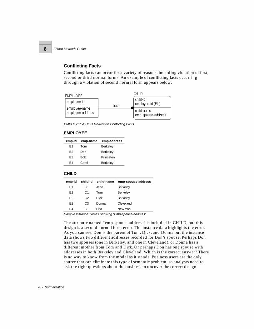
6 ERwin Methods Guide
78 • Normalization
Conflicting FactsConflicting facts can occur for a variety of reasons, including violation of first,second or third normal forms. An example of conflicting facts occurringthrough a violation of second normal form appears below:
EMPLOYEE-CHILD Model with Conflicting Facts
EMPLOYEE
emp-id emp-name emp-address
E1 Tom Berkeley
E2 Don Berkeley
E3 Bob Princeton
E4 Carol Berkeley
CHILD
emp-id child-id child-name emp-spouse-address
E1 C1 Jane Berkeley
E2 C1 Tom Berkeley
E2 C2 Dick Berkeley
E2 C3 Donna Cleveland
E4 C1 Lisa New York
Sample Instance Tables Showing “Emp-spouse-address”
The attribute named “emp-spouse-address” is included in CHILD, but thisdesign is a second normal form error. The instance data highlights the error.As you can see, Don is the parent of Tom, Dick, and Donna but the instancedata shows two different addresses recorded for Don’s spouse. Perhaps Donhas two spouses (one in Berkeley, and one in Cleveland), or Donna has adifferent mother from Tom and Dick. Or perhaps Don has one spouse withaddresses in both Berkeley and Cleveland. Which is the correct answer? Thereis no way to know from the model as it stands. Business users are the onlysource that can eliminate this type of semantic problem, so analysts need toask the right questions about the business to uncover the correct design.
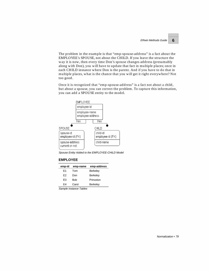
ERwin Methods Guide 6
Normalization • 79
The problem in the example is that “emp-spouse-address” is a fact about theEMPLOYEE’s SPOUSE, not about the CHILD. If you leave the structure theway it is now, then every time Don’s spouse changes address (presumablyalong with Don), you will have to update that fact in multiple places; once ineach CHILD instance where Don is the parent. And if you have to do that inmultiple places, what is the chance that you will get it right everywhere? Nottoo good.
Once it is recognized that “emp-spouse-address” is a fact not about a child,but about a spouse, you can correct the problem. To capture this information,you can add a SPOUSE entity to the model.
Spouse Entity Added to the EMPLOYEE-CHILD Model
EMPLOYEE
emp-id emp-name emp-address
E1 Tom Berkeley
E2 Don Berkeley
E3 Bob Princeton
E4 Carol Berkeley
Sample Instance Tables
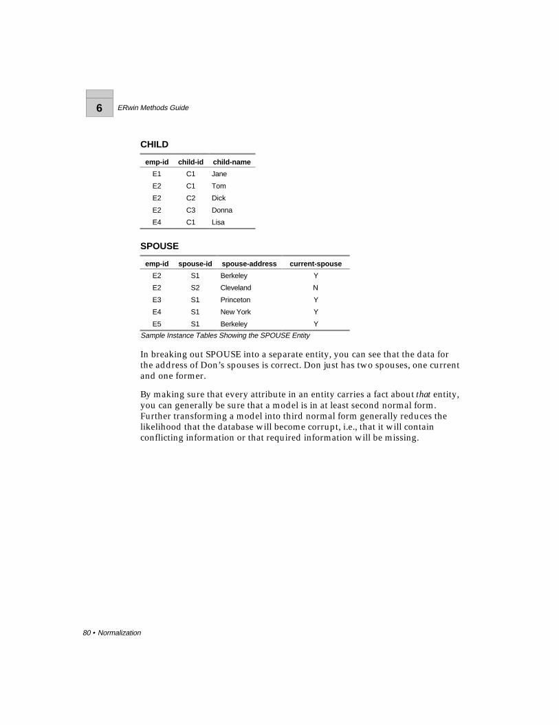
6 ERwin Methods Guide
80 • Normalization
CHILD
emp-id child-id child-name
E1 C1 Jane
E2 C1 Tom
E2 C2 Dick
E2 C3 Donna
E4 C1 Lisa
SPOUSE
emp-id spouse-id spouse-address current-spouse
E2 S1 Berkeley Y
E2 S2 Cleveland N
E3 S1 Princeton Y
E4 S1 New York Y
E5 S1 Berkeley Y
Sample Instance Tables Showing the SPOUSE Entity
In breaking out SPOUSE into a separate entity, you can see that the data forthe address of Don’s spouses is correct. Don just has two spouses, one currentand one former.
By making sure that every attribute in an entity carries a fact about that entity,you can generally be sure that a model is in at least second normal form.Further transforming a model into third normal form generally reduces thelikelihood that the database will become corrupt, i.e., that it will containconflicting information or that required information will be missing.

ERwin Methods Guide 6
Normalization • 81
Derived AttributesAnother example of conflicting facts occurs when third normal form isviolated. For example, if you included both a “birth-date” and an “age”attribute as non-key attributes in the CHILD entity, you violate third normalform. This is because “age” is functionally dependent on “birth-date.” Byknowing “birth-date” and the date today, you can derive the “age” of theCHILD.
Derived attributes are those that may be computed from other attributes (e.g.,totals) and therefore need not be stored directly. To be accurate, derivedattributes need to be updated every time their derivation source(s) is updated.This creates a large overhead in an application that does batch loads orupdates, for example, and puts the responsibility on application designers andcoders to ensure that the updates to derived facts are performed.
A goal of normalization is to ensure that there is only one way to know eachfact recorded in the database. If you know the value of a derived attribute,and you know the algorithm by which it is derived and the values of theattributes used by the algorithm, then there are two ways to know the fact(look at the value of the derived attribute, or derive it from scratch). If youcan get an answer two different ways, it is possible that the two answers willbe different.
For example, you can choose to record both the “birth-date” and the “age” forCHILD. And suppose that the “age” attribute is only changed in the databaseduring an end of month maintenance job. Then, when you ask the question,“How old is such and such CHILD?” you can directly access “age” and get ananswer, or you can, at that point, subtract “birth-date” from “today’s-date.” Ifyou did the subtraction, you would always get the right answer. If “age” hasnot been updated recently, it might give you the wrong answer, and therewould always be the potential for conflicting answers.
There are situations, where it makes sense to record derived data in themodel, particularly if the data is expensive to compute. It can also be veryuseful in discussing the model with the business. Although the theory ofmodeling says that you should never include derived data (and you shoulddo so only sparingly), break the rules when you must. But at least record thefact that the attribute is derived and state the derivation algorithm.

6 ERwin Methods Guide
82 • Normalization
Missing InformationMissing information in a model can sometimes result from efforts tonormalize the data. In the example, adding the SPOUSE entity to theEMPLOYEE-CHILD model improves the design, but destroys the implicitrelationship between the CHILD entity and the SPOUSE address. It is possiblethat the reason that “emp-spouse-address” was stored in the CHILD entity inthe first place was to represent the address of the other parent of the child(which was assumed to be the spouse). If you need to know the other“parent” of each of the children, then you must add this information to theCHILD entity.
Replacing Missing Information Using a New Relationship
EMPLOYEE
emp-id emp-name emp-address
E1 Tom Berkeley
E2 Don Berkeley
E3 Bob Princeton
E4 Carol Berkeley
CHILD
emp-id child-id child-name other-parent-id
E1 C1 Jane —
E2 C1 Tom S1
E2 C2 Dick S1
E2 C3 Donna S2
E4 C1 Lisa S1
Sample Instance Tables for EMPLOYEE, CHILD, and SPOUSE
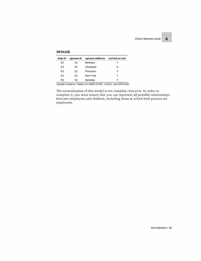
ERwin Methods Guide 6
Normalization • 83
SPOUSE
emp-id spouse-id spouse-address current-or-not
E2 S1 Berkeley Y
E2 S2 Cleveland N
E3 S1 Princeton Y
E4 S1 New York Y
E5 S1 Berkeley Y
Sample Instance Tables for EMPLOYEE, CHILD, and SPOUSE
The normalization of this model is not complete, however. In order tocomplete it, you must ensure that you can represent all possible relationshipsbetween employees and children, including those in which both parents areemployees.
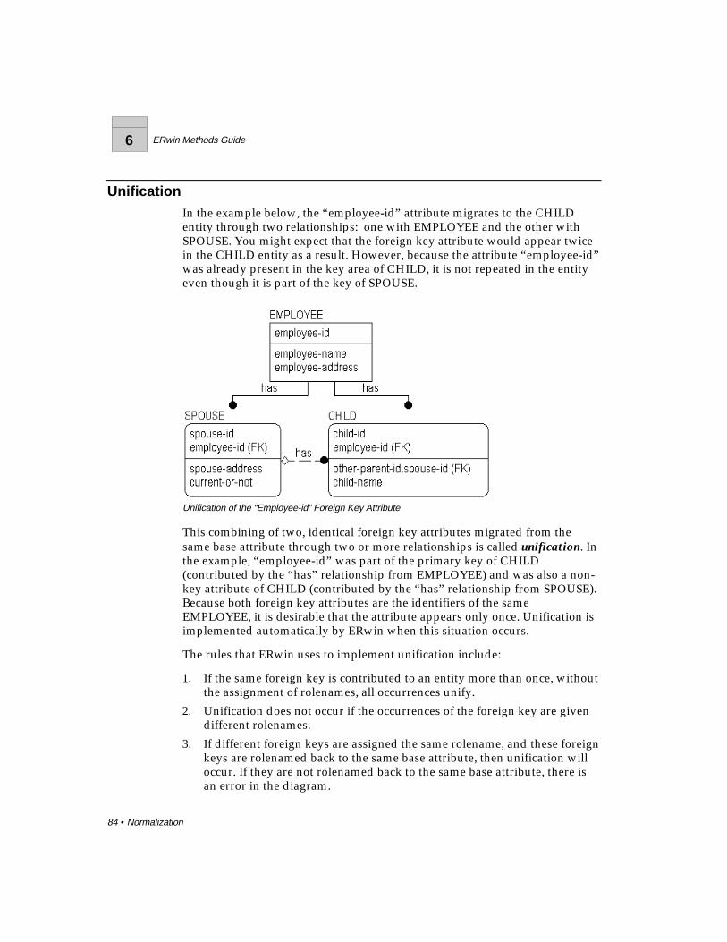
6 ERwin Methods Guide
84 • Normalization
UnificationIn the example below, the “employee-id” attribute migrates to the CHILDentity through two relationships: one with EMPLOYEE and the other withSPOUSE. You might expect that the foreign key attribute would appear twicein the CHILD entity as a result. However, because the attribute “employee-id”was already present in the key area of CHILD, it is not repeated in the entityeven though it is part of the key of SPOUSE.
Unification of the “Employee-id” Foreign Key Attribute
This combining of two, identical foreign key attributes migrated from thesame base attribute through two or more relationships is called unification. Inthe example, “employee-id” was part of the primary key of CHILD(contributed by the “has” relationship from EMPLOYEE) and was also a non-key attribute of CHILD (contributed by the “has” relationship from SPOUSE).Because both foreign key attributes are the identifiers of the sameEMPLOYEE, it is desirable that the attribute appears only once. Unification isimplemented automatically by ERwin when this situation occurs.
The rules that ERwin uses to implement unification include:
1. If the same foreign key is contributed to an entity more than once, withoutthe assignment of rolenames, all occurrences unify.
2. Unification does not occur if the occurrences of the foreign key are givendifferent rolenames.
3. If different foreign keys are assigned the same rolename, and these foreignkeys are rolenamed back to the same base attribute, then unification willoccur. If they are not rolenamed back to the same base attribute, there isan error in the diagram.

ERwin Methods Guide 6
Normalization • 85
4. If any of the foreign keys that unify are part of the primary key of theentity, the unified attribute will remain as part of the primary key.
5. If none of the foreign keys that unify are part of the primary key, theunified attribute will not be part of the primary key.
Accordingly, you can override the unification of foreign keys, whennecessary, by assigning rolenames. If you want the same foreign key to appeartwo or more times in a child entity, you can add a rolename to each foreignkey attribute.
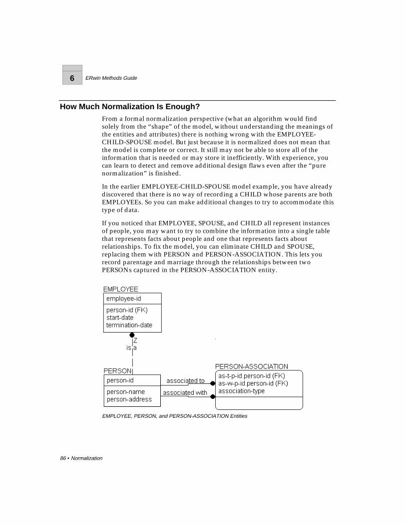
6 ERwin Methods Guide
86 • Normalization
How Much Normalization Is Enough?From a formal normalization perspective (what an algorithm would findsolely from the “shape” of the model, without understanding the meanings ofthe entities and attributes) there is nothing wrong with the EMPLOYEE-CHILD-SPOUSE model. But just because it is normalized does not mean thatthe model is complete or correct. It still may not be able to store all of theinformation that is needed or may store it inefficiently. With experience, youcan learn to detect and remove additional design flaws even after the “purenormalization” is finished.
In the earlier EMPLOYEE-CHILD-SPOUSE model example, you have alreadydiscovered that there is no way of recording a CHILD whose parents are bothEMPLOYEEs. So you can make additional changes to try to accommodate thistype of data.
If you noticed that EMPLOYEE, SPOUSE, and CHILD all represent instancesof people, you may want to try to combine the information into a single tablethat represents facts about people and one that represents facts aboutrelationships. To fix the model, you can eliminate CHILD and SPOUSE,replacing them with PERSON and PERSON-ASSOCIATION. This lets yourecord parentage and marriage through the relationships between twoPERSONs captured in the PERSON-ASSOCIATION entity.
EMPLOYEE, PERSON, and PERSON-ASSOCIATION Entities

ERwin Methods Guide 6
Normalization • 87
In this structure, you can finally record any number of relationships betweentwo PERSONs, as well as a number of relationships you could not recordbefore. For example, the previous model had not considered “adoption.” Thenew structure, however, automatically covers it. To represent “adoption” youcan add a new value to the “person-association-type” validation rule torepresent adopted parentage. You can also add “legal guardian,” “significantother,” or other relationships between two PERSONs later, if needed.
EMPLOYEE remains an independent entity, because the business chooses toidentify EMPLOYEEs differently from PERSONs. However, EMPLOYEEinherits the properties of PERSON by virtue of the “is a” relationship back toPERSON. Notice the “Z” on that relationship and the absence of a diamond.This is a one-to-zero or one relationship that can sometimes be used in placeof a subtype when the subtype entities require different keys. In this example,a PERSON either “is an” EMPLOYEE or “is not an” EMPLOYEE.
If you wanted to use the same key for both PERSON and EMPLOYEE, youcould have “encased” the EMPLOYEE entity into PERSON and allowed itsattributes to be NULL whenever the PERSON was not an EMPLOYEE. Youstill could have specified that the business wanted to look up “employees” bya separate identifier, but the business statements would have been a bitdifferent. This structure is shown below.
Generalized Employee Model Construct
ConclusionsWhat this all basically comes down to in the end is that a model may“normalize,” but may still not be a correct representation of the business.Formal normalization is important. Verifying that the model meanssomething, perhaps with sets of sample instance tables as done here, is no lessimportant.
6 ERwin Methods Guide
88 • Normalization
ERwin Support for NormalizationERwin provides some support for normalization of data models, but does notcurrently contain a full normalization algorithm. If you have not used a “realtime” modeling tool before, you will find ERwin’s standard modeling featuresquite helpful. They will prevent you from making many normalization errors.
First Normal Form SupportIn a model, each entity or attribute is identified by its “name.” ERwin willaccept any name for an object, with the following exceptions:
♦ ERwin will flag a second use of an entity name (depending on yourpreference for unique names).
♦ ERwin will flag a second use of an attribute name, unless that name is arolename. When rolenames are assigned, the same name for an attributemay be used in different entities.
♦ ERwin will not let you bring a foreign key into an entity more than oncewithout unifying the like columns.
By preventing multiple uses of the same name, ERwin is basically promptingyou to put each fact in exactly one place. There may still be second normalform errors if you place an attribute incorrectly, but no algorithm would findthat without more information than is present in a model.
In the data model, ERwin cannot know that a name you assign to an attributecan represent a “list” of things. For example, ERwin accepts “children's-names” as an attribute name in our earlier example. So ERwin does notdirectly guarantee that every model is in first normal form.
However, the DBMS schema function of ERwin does not support a data typeof “list.” Because the schema is a representation of the database in a physicalrelational system, first normal form errors are also prevented at this level.

ERwin Methods Guide 6
Normalization • 89
Second and Third Normal Form SupportERwin does not currently know about functional dependencies, but it canhelp to prevent second and third normal form errors. For example, if youreconstruct the examples presented earlier in this chapter, you will find thatonce “spouse-address” has been defined as an attribute of SPOUSE, youcannot also define it as an attribute of CHILD. (Again, depending on yourpreference for unique names.)
By preventing the multiple occurrence of foreign keys without rolenames,ERwin is reminding you to think about what the structure represents. If thesame foreign key occurs twice in the same entity, there is a business questionto ask:
Are we recording the keys of two separate instances, or do both of thekeys represent the same instance?
When the foreign keys represent different instances, separate rolenames areneeded. If the two foreign keys represent the same instance, then there is verylikely a normalization error somewhere. A foreign key appearing twice in anentity, without a rolename, is a dead giveaway that there is a redundantrelationship structure in the model. When two foreign keys are assigned thesame rolename, unification occurs.

6 ERwin Methods Guide
90 • Normalization
ERwin Methods Guide 7
Creating a Physical Model • 91
Creating a Physical Model
What’s in This Chapter?The objective of a physical model is to provide a database administrator withsufficient information to create an efficient physical database. The physicalmodel also provides a context for the definition and for recording in the datadictionary of the data elements that form the database, and assists theapplication team in choosing a physical structure for the programs that willaccess the data. To ensure that all information system needs are met, physicalmodels are often developed jointly by a team representing the dataadministration, database administration, and application development areas.
When deemed appropriate for the development effort, the model can alsoprovide the basis for comparing the physical database design against theoriginal business information requirements:
♦ To demonstrate that the physical database design adequately supportsthose requirements.
♦ To document physical design choices and their implications (e.g., what issatisfied, and what is not).
♦ To identify database extensibility capabilities and constraints.
ERwin provides support for both roles of a physical model: generating thephysical database and documenting physical design against the businessrequirements. For example, you can create a physical model from an ERD,key-based, or fully attributed model simply by changing the view of themodel from “Logical Model” to “Physical Model.” Each option in the logicalmodel has a corresponding option in the physical model. So each entitybecomes a relational table, attributes become columns, and keys becomeindices.
Once the physical model is created, ERwin can generate all model objects inthe correct syntax for the selected target server; directly to the catalog of thetarget server, or indirectly, as a schema DDL script file.
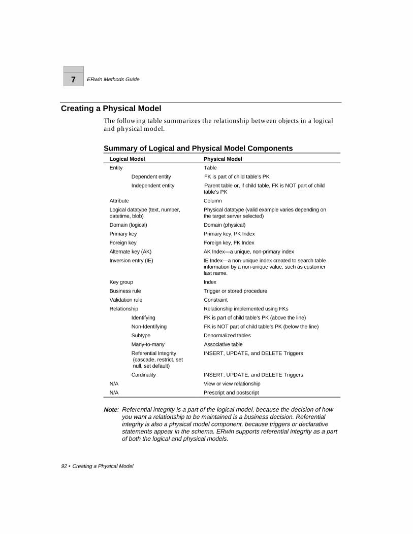
7 ERwin Methods Guide
92 • Creating a Physical Model
Creating a Physical ModelThe following table summarizes the relationship between objects in a logicaland physical model.
Summary of Logical and Physical Model ComponentsLogical Model Physical Model
Entity Table
Dependent entity FK is part of child table’s PK
Independent entity Parent table or, if child table, FK is NOT part of childtable’s PK
Attribute Column
Logical datatype (text, number,datetime, blob)
Physical datatype (valid example varies depending onthe target server selected)
Domain (logical) Domain (physical)
Primary key Primary key, PK Index
Foreign key Foreign key, FK Index
Alternate key (AK) AK Index—a unique, non-primary index
Inversion entry (IE) IE Index—a non-unique index created to search tableinformation by a non-unique value, such as customerlast name.
Key group Index
Business rule Trigger or stored procedure
Validation rule Constraint
Relationship Relationship implemented using FKs
Identifying FK is part of child table’s PK (above the line)
Non-Identifying FK is NOT part of child table’s PK (below the line)
Subtype Denormalized tables
Many-to-many Associative table
Referential Integrity (cascade, restrict, set null, set default)
INSERT, UPDATE, and DELETE Triggers
Cardinality INSERT, UPDATE, and DELETE Triggers
N/A View or view relationship
N/A Prescript and postscript
Note : Referential integrity is a part of the logical model, because the decision of howyou want a relationship to be maintained is a business decision. Referentialintegrity is also a physical model component, because triggers or declarativestatements appear in the schema. ERwin supports referential integrity as a partof both the logical and physical models.
ERwin Methods Guide 7
Creating a Physical Model • 93
DenormalizationERwin also lets you denormalize the structure of the logical model so that youcan build a related physical model that is designed effectively for the targetRDBMS. Features supporting denormalization include:
♦ “Logical only” properties for entities, attributes, key groups, anddomains. You can mark any item in the logical model “logical only” sothat it appears in the logical model, but does not appear in the physicalmodel. For example, you can use the “logical only” settings todenormalize subtype relationships or support partial key migration in thephysical model.
♦ “Physical only” properties for tables, columns, indexes, and domains. Youcan mark any item in the physical model “physical only” so that it appearsin the physical model only. This setting also support denormalization ofthe physical model because it enables the modeler to include tables,columns, and indexes in the physical model that directly support physicalimplementation requirements.
♦ Resolution of many-to-many relationships in a physical model. ERwinprovides support for resolving many-to-many relationships in both thelogical and physical models. If you resolve the many-to-many relationshipin the logical model, ERwin creates the associative entity and lets you addadditional attributes. If you choose to keep the many-to-many relationshipin the logical model, you can still resolve the relationship in the physicalmodel. ERwin maintains the link between the original logical design andthe new physical design, so the origin of the associative table isdocumented in the model.

7 ERwin Methods Guide
94 • Creating a Physical Model
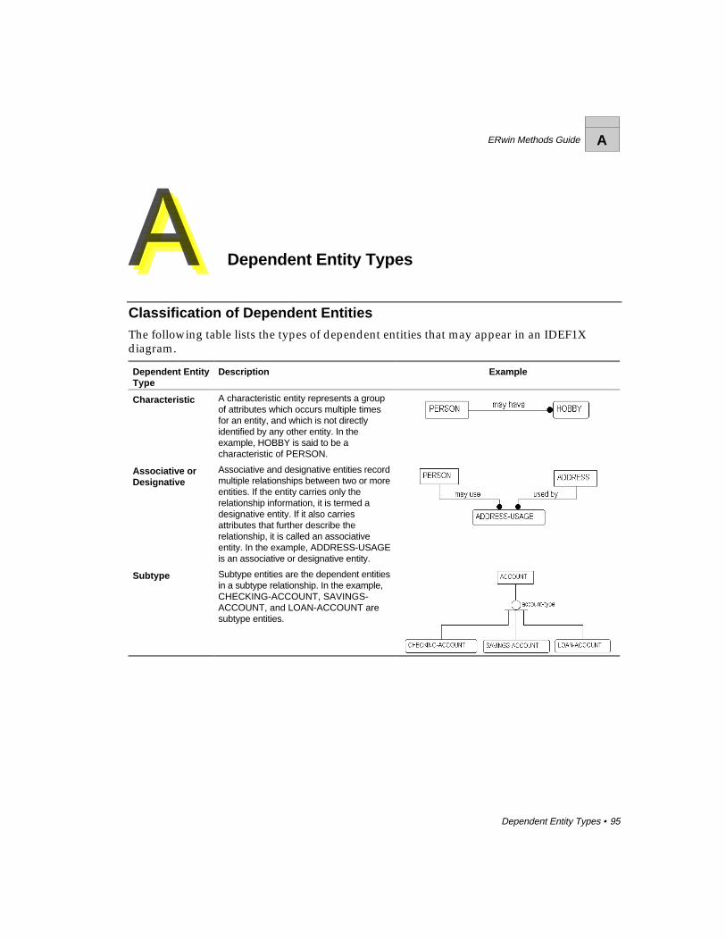
ERwin Methods Guide A
Dependent Entity Types • 95
Dependent Entity Types
Classification of Dependent EntitiesThe following table lists the types of dependent entities that may appear in an IDEF1Xdiagram.
Dependent EntityType
Description Example
Characteristic A characteristic entity represents a groupof attributes which occurs multiple timesfor an entity, and which is not directlyidentified by any other entity. In theexample, HOBBY is said to be acharacteristic of PERSON.
Associative orDesignative
Associative and designative entities recordmultiple relationships between two or moreentities. If the entity carries only therelationship information, it is termed adesignative entity. If it also carriesattributes that further describe therelationship, it is called an associativeentity. In the example, ADDRESS-USAGEis an associative or designative entity.
Subtype Subtype entities are the dependent entitiesin a subtype relationship. In the example,CHECKING-ACCOUNT, SAVINGS-ACCOUNT, and LOAN-ACCOUNT aresubtype entities.

A ERwin Methods Guide
96 • Dependent Entity Types
ERwin Methods Guide
Glossary of Terms • 89
Glossary of Terms
Alternate Key1) An attribute or attributes that uniquely identify an instance of an entity.
2) If more than one attribute or group of attributes satisfies rule 1, thealternate keys are those attributes or groups of attributes not selected as theprimary key.
ERwin will generate a unique index for each alternate key.
AttributeAn attribute represents a type of characteristic or property associated with aset of real or abstract things (people, places, events, etc.).
BasenameThe original name of a rolenamed foreign key.
Binary RelationshipA relationship in which exactly one instance of the parent is related to zero,one, or more instances of a child. In IDEF1X, identifying, non-identifying, andsubtype relationships are all binary relationships.
CardinalityThe ratio of instances of a parent to instances of a child. In IDEF1X, thecardinality of binary relationships is 1:n, whereby n may be one of thefollowing:
Zero, one, or more (signified by a blank space)
One or more (signified by the letter P)
Zero or one (signified by the letter Z)
Exactly n (where n is some number)

ERwin Methods Guide
90 • Glossary of Terms
Complete Subtype ClusterIf the subtype cluster includes all of the possible subtypes (every instance ofthe generic parent is associated with one subtype), then the subtype cluster iscomplete. For example, every EMPLOYEE is either male or female, andtherefore the subtype cluster of MALE-EMPLOYEE and FEMALE-EMPLOYEE is a complete subtype cluster.
Dependent EntityAn entity whose instances cannot be uniquely identified without determiningits relationship to another entity or entities.
DiscriminatorThe value of an attribute in an instance of the generic parent determines towhich of the possible subtypes that instance belongs. This attribute is knownas the discriminator. For example, the value in the attribute Sex in an instanceof EMPLOYEE determines to which particular subtype (MALE-EMPLOYEEor FEMALE-EMPLOYEE) that instance belongs.
EntityAn entity represents a set of real or abstract things (people, places, events,etc.) which have common attributes or characteristics. Entities may be eitherindependent, or dependent.
Foreign KeyAn attribute that has migrated through a relationship from a parent entity to achild entity. A foreign key represents a secondary reference to a single set ofvalues; the primary reference being the owned attribute.
Identifying RelationshipA relationship whereby an instance of the child entity is identified through itsassociation with a parent entity. The primary key attributes of the parententity become primary key attributes of the child.
Incomplete Subtype ClusterIf the subtype cluster does not include all of the possible subtypes (everyinstance of the generic parent is not associated with one subtype), then thesubtype cluster is incomplete. For example, if some employees arecommissioned, a subtype cluster of SALARIED-EMPLOYEE and PART-TIMEEMPLOYEE would be incomplete.
ERwin Methods Guide
Glossary of Terms • 91
Independent EntityAn entity whose instances can be uniquely identified without determining itsrelationship to another entity.
Inversion EntryAn attribute or attributes that do not uniquely identify an instance of anentity, but are often used to access instances of entities. ERwin will generate anon-unique index for each inversion entry.
Non-key attributeAny attribute that is not part of the entity's primary key. Non-key attributesmay be part of an inversion entry or alternate key, and may also be foreignkeys.
Non-Identifying RelationshipA relationship whereby an instance of the child entity is not identified throughits association with a parent entity. The primary key attributes of the parententity become non-key attributes of the child.
Nonspecific RelationshipBoth parent-child connection and subtype relationships are considered to bespecific relationships because they define precisely how instances of one entityrelate to instances of another. However, in the initial development of a model,it is often helpful to identify "non-specific relationships" between two entities.A nonspecific relationship, also referred to as a "many-to-many relationship,"is an association between two entities in which each instance of the first entityis associated with zero, one, or many instances of the second entity and eachinstance of the second entity is associated with zero, one, or many instances ofthe first entity.
Primary KeyAn attribute or attributes that uniquely identify an instance of an entity. Ifmore than one attribute or group of attributes can uniquely identify eachinstance, the primary key is chosen from this list of candidates based on itsperceived value to the business as an identifier. Ideally, primary keys shouldnot change over time and should be as small as possible. ERwin will generatea unique index for each primary key.
ERwin Methods Guide
92 • Glossary of Terms
Referential IntegrityThe assertion that the foreign key values in an instance of a child entity havecorresponding values in a parent entity.
RolenameA new name for a foreign key. A rolename is used to indicate that the set ofvalues of the foreign key is a subset of the set of values of the attribute in theparent, and performs a specific function (or role) in the entity.
SchemaThe structure of a database. Usually refers to the DDL (data definitionlanguage) script file. DDL consists of CREATE TABLE, CREATE INDEX, andother statements.
Specific RelationshipA specific relationship is an association between entities in which eachinstance of the parent entity is associated with zero, one, or many instances ofthe child entity, and each instance of the child entity is associated with zero orone instance of the parent entity.
Subtype EntityThere are often entities which are specific types of other entities. For example,a SALARIED EMPLOYEE is a specific type of EMPLOYEE. Subtype entitiesare useful for storing information that only applies to a specific subtype. Theyare also useful for expressing relationships that are only valid for that specificsubtype, such as the fact that a SALARIED EMPLOYEE will qualify for acertain BENEFIT, while a PART-TIME-EMPLOYEE will not. In IDEF1X,subtypes within a subtype cluster are mutually exclusive.
Subtype RelationshipA subtype relationship (also known as a categorization relationship) is arelationship between a subtype entity and its generic parent. A subtyperelationship always relates one instance of a generic parent with zero or oneinstance of the subtype.
ERwin Methods Guide
Index • 93
Index
11NFdefinition, 72
22NFdefinition, 72
33NFdefinition, 72
AAliasentity names, 39Alternate key, 31Associative entity, 58definition, 95Attributeavoiding multiple occurrences,
77avoiding multiple usages, 75avoiding synonyms and
homonyms, 39definition, 21, 43definition using business terms,
42derived, 81in an ERD, 20key and non-key, 28name, 38rolename, 36specifying a domain of values, 43specifying a rolename, 44validation rule in definition, 43
BBase attributedefinition, 45Binary relationshipdefinition, 60BPwinprocess modeling, 11Business rulecapturing in a definition, 46Business termorganizing, 42
CCandidate keydefinition, 29Cardinalitydefinition, 48in identifying relationships, 48in non-identifying relationships,
49notation in IDEF1X and IE, 48Cascadedefinition, 52example, 54Characteristic entitydefinition, 95Child entity, 22Complete subtype relationships,
67Componentsin an ERD, 20
DData analystrole, 12Data area, 28Data modeluse of verb phrases, 24Data modelerrole, 12Data modelinganalysis of process, 11assertion examples, 25benefits, 10, 18definition, 10methodologies, 10sample IDEF1X methodology, 14

ERwin Methods Guide
94 • Index
sessions, 12Definitionattribute, 43capturing business rules, 46entity, 40rolename, 44Denormalizationin the physical model, 93Dependencyexistance, 32identification, 32Dependent entity, 32types of, 95Derived attributedefinition, 81when to use, 81Designative entitydefinition, 95Discriminatorin subtype relationships, 65Domainspecifying valid attribute values,
43
EEntityassigning a definition, 40associative, 58, 95avoiding circular definitions, 42avoiding synonyms and
homonyms, 39characteristic, 95child entity, 22definition, 21definition conventions, 40definition description, 40definition using business terms,
42dependent, 32designative, 95in an ERD, 20independent, 33name, 38parent, 22subtype, 64, 95supertype, 64Entity Relationship Diagramcreating, 20definition, 16
objective, 19overview, 19sample, 20subject areas, 19ERD. See also Entity
Relationship DiagramERwin diagramcomponents, 20ERwin modeladvantages, 18Exclusive subtype relationships,
68Existence dependency, 32
FFacilitatorrole, 12First normal form, 73, 75definition, 72Foreign keyassigning referential integrity, 51unification, 45Foreign key attributerolename, 36Full functional dependence, 72Fully attributed model, 14definition, 16
GGeneralization categorydefinition, 64Generalization hierarchydefinition, 64Glossarycreating a business glossary, 42
IIDEF1Xorigin, iiiIdentification dependency, 32Identifying relationship, 33cardinality, 48IEorigin, iiiInclusive subtype relationships,
68

ERwin Methods Guide
Index • 95
Incomplete subtype relationships,67
Independent entity, 33Information systempurpose, 9requirements, 9Inheritance hierarchydefinition, 64Instancedefinition, 21Inversion entry, 31
KKeyalternate key, 31data area, 28definition, 28foreign key attributes, 32inversion entry, 31migration, 32primary, 28selection example, 29surrogate, 30Key attributes, 28Key based modeldefinition, 16, 27objective, 27
LLogical modelcorresponding physical model
constructs, 92definition, 16Logical only property, 93
MManagerrole, 13Many-to-many, 23, 56, 57eliminating, 58Migratingrolename, 36
NNaming
attributes, 38entities, 38N-ary relationship, 56definition, 60Non-identifying relationship, 34cardinality, 49Non-key attribute, 28Normal Formsfull functional dependence, 72summary of six forms, 72Normalizationavoiding design problems, 73,
75, 77, 80, 81completing, 86denormalizing in the physical
model, 93ERwin support, 88First Normal Form, 73, 75Second Normal Form, 77Third Normal Form, 80, 81
OOne-to-many, 22
PParent entity, 22Physical modelcorresponding logical model
constructs, 92creating, 91definition, 17Physical only property, 93Primary key, 28choosing, 29Process modeling, 11
RRecursive relationship, 56definition, 62Referential integrity, 51cascade, 52definition, 52example, 54, 55notation in an ERwin diagram,
53restrict, 52set default, 52

ERwin Methods Guide
96 • Index
set null, 52Relationshipand dependent entities, 32and independent entities, 33complete subtype, 67definition, 22enforcing cardinality, 48exclusive subtype, 68identifying, 33in an ERD, 20inclusive subtype, 68incomplete subtype, 67mandatory and optional, 49many-to-many, 23, 56, 57n-ary, 56, 60non-identifying, 34one-to-many, 22reading from child to parent, 24reading from parent to child, 24recursive, 56, 62referential integrity, 51subtype, 56subtype (category), 64subtype notation, 69verb phrase, 23Repeating data groups, 73Restrictdefinition, 52example, 54Rolenameassigning a definition, 44definition, 36migrating, 36
SSecond Normal Form, 77definition, 72Sessionplanning, 12roles, 12Set defaultdefinition, 52Set nulldefinition, 52example, 55Subject matter expertrole, 13Subtype entitydefinition, 95
Subtype relationship, 56complete, 67creating, 70definition, 64discriminator, 65exclusive, 68inclusive, 68incomplete, 67notation, 69supertypes, 64Supertypes, 64Surrogate keyassigning, 30
TThird normal form, 80, 81definition, 72fully-attributed model, 16key based model, 16Transformation model, 14creating, 91definition, 17
UUnificationavoiding normalization
problems, 84foreign key rolenaming, 45
VValidation rulein attribute definitions, 43Verb phrase, 23example, 23in a data model, 24
Documentation Comments Form ERwin Version 3.0Methods Guide
Logic Works is interested in your feedback on this documentation. You can use this form ifyou have compliments or questions, or would like to report problems in the documentation.
Please fax or mail completed forms to:
Documentation ManagerLogic Works, Inc.University Square at Princeton111 Campus DrivePrinceton, NJ 08540
Fax: (609) 514-0184
Comments:
Please enter your comments in the space provided below:
_________________________________________________________________________________
_________________________________________________________________________________
_________________________________________________________________________________
_________________________________________________________________________________
_________________________________________________________________________________
_________________________________________________________________________________
_________________________________________________________________________________
_________________________________________________________________________________
_________________________________________________________________________________
_________________________________________________________________________________
_________________________________________________________________________________
Please include your name, address, and telephone number in the space below:
_________________________________________________________________________________
_________________________________________________________________________________
_________________________________________________________________________________
Would you like a Logic Works representative to contact you? Yes � No �