methods for wheel rotation modelling - chalmers
TRANSCRIPT
Introduction MRF implementation MRF modifications Test case Conclusion
Methods for wheel rotation modelling
Erik Josefsson
Mechanics and Maritime Sciences/Vehicle Engineering and Autonomous Systems,Chalmers University of Technology,
Gothenburg, Sweden
January 15, 2021
Erik Josefsson Methods for wheel rotation modelling January 15, 2021 1 / 45

Introduction MRF implementation MRF modifications Test case Conclusion
Background
Road vehicles contribute to a significant part of the global CO2 emissions
Car companies strive to reduce the energy consumption of their vehicles
Reduced emissions for combustion vehiclesIncreased range for electric vehicles
At velocities above 60 km/h aerodynamic drag is the largest resisting force
Approximately 25% of the drag can be attributed to the wheels
There is a need for methods that accurately predicts the flow around wheels
Erik Josefsson Methods for wheel rotation modelling January 15, 2021 2 / 45

Introduction MRF implementation MRF modifications Test case Conclusion
Wheel rotation modelling
Two main challenges when modelling rotating wheels
Geometry replication
Static tyre deformations from the vehicle weightDynamic tyre deformations from the rotational forces
Realistic boundary conditions
How can a rotating tyre be represented in an accurate, but stillcomputationally affordable, way?
This work will focus on the boundary conditions.
Erik Josefsson Methods for wheel rotation modelling January 15, 2021 3 / 45
Introduction MRF implementation MRF modifications Test case Conclusion
Wheel nomenclature
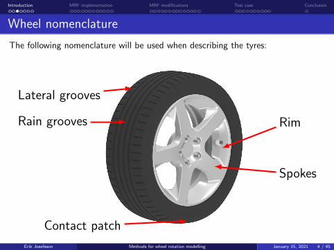
The following nomenclature will be used when describing the tyres:
Rim
Spokes
Contact patch
Rain grooves
Lateral grooves
Erik Josefsson Methods for wheel rotation modelling January 15, 2021 4 / 45

Introduction MRF implementation MRF modifications Test case Conclusion
Rotating wall
The rotating wall boundary condition applies a velocity tangential to the surface.
+ Can be used either steady or unsteady
+ Can be used for non-circular geometries
− Only applies a velocity tangential to the surface, can not model the flowbetween spokes of a rim or in the lateral grooves of a tyre
Erik Josefsson Methods for wheel rotation modelling January 15, 2021 5 / 45
Introduction MRF implementation MRF modifications Test case Conclusion
Multiple reference frame (MRF)
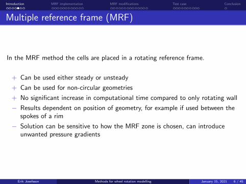
In the MRF method the cells are placed in a rotating reference frame.
+ Can be used either steady or unsteady
+ Can be used for non-circular geometries
+ No significant increase in computational time compared to only rotating wall
− Results dependent on position of geometry, for example if used between thespokes of a rim
− Solution can be sensitive to how the MRF zone is chosen, can introduceunwanted pressure gradients
Erik Josefsson Methods for wheel rotation modelling January 15, 2021 6 / 45

Introduction MRF implementation MRF modifications Test case Conclusion
Rotating mesh
In the rotating mesh method the mesh is rotated at every time step.
+ Actually rotates the geometry
− Only circular geometries, not suitable for a tyre with a contact patch
− Only unsteady simulations
− Increases computational cost
Erik Josefsson Methods for wheel rotation modelling January 15, 2021 7 / 45

Introduction MRF implementation MRF modifications Test case Conclusion
Hybrid methods
By leveraging the benefits of the different methods some of the drawbacks can behandled by constructing hybrid methods.
The MRFg method (MRF grooves) was proposed by Hobeika and Sebben
Rim - rotating mesh
Tyre surface and rain grooves - rotating wall
Lateral grooves - MRF
Erik Josefsson Methods for wheel rotation modelling January 15, 2021 8 / 45

Introduction MRF implementation MRF modifications Test case Conclusion
Files and directories
MRF is implemented as a part of finiteVolume and can be found in$FOAM_SRC/finiteVolume/cfdTools/general/MRF.
Here we will investigate the implementation of MRF in pimpleFoam but it shouldnot differ significantly between solvers.
pimpleFoam can be found in$FOAM_APP/solvers/incompressible/pimpleFoam.
Erik Josefsson Methods for wheel rotation modelling January 15, 2021 9 / 45

Introduction MRF implementation MRF modifications Test case Conclusion
Implementation in pimpleFoam
At the end of createFields.H (included in the beginning of pimpleFoam.C)#include "createMRF.H"; is found. This is found in$FOAM_SRC/finiteVolume/cfdTools/general/include/createMRF.H andcontains a single line:
IOMRFZoneList MRF(mesh);.
(Found in $FOAM_SRC/finiteVolume/cfdTools/general/MRF)
Erik Josefsson Methods for wheel rotation modelling January 15, 2021 10 / 45
Introduction MRF implementation MRF modifications Test case Conclusion
IOMRFZoneList
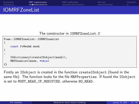
The constructor in IOMRFZoneList.C
Foam::IOMRFZoneList::IOMRFZoneList
(
const fvMesh& mesh
)
:
IOdictionary(createIOobject(mesh)),
MRFZoneList(mesh, *this)
Firstly an IOobject is created in the function createIOobject (found in thesame file). The function looks for the file MRFProperties. If found the IOobject
is set to MUST_READ_IF_MODIFIED, otherwise NO_READ.
Erik Josefsson Methods for wheel rotation modelling January 15, 2021 11 / 45

Introduction MRF implementation MRF modifications Test case Conclusion
MRFProperties
Example of MRFProperties
MRF1
cellZone mrfgZone;
active yes;
// Fixed patches (by default they ’move’ with the MRF zone)
nonRotatingPatches ();
origin (0 0 0);
axis (0 1 0);
omega -194.45;
Here one MRF zone named MRF1 was created to act on the cellZone mrfgZone.The origin and axis of the rotation was specified as well as the rotational velocity(rad/s).
After the dictionary is read MRFZoneList is called.
Erik Josefsson Methods for wheel rotation modelling January 15, 2021 12 / 45
Introduction MRF implementation MRF modifications Test case Conclusion
MRFZoneList
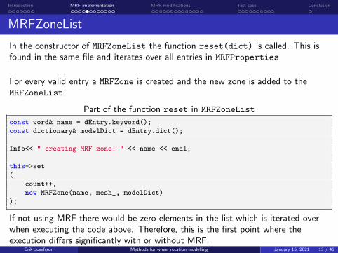
In the constructor of MRFZoneList the function reset(dict) is called. This isfound in the same file and iterates over all entries in MRFProperties.
For every valid entry a MRFZone is created and the new zone is added to theMRFZoneList.
Part of the function reset in MRFZoneList
const word& name = dEntry.keyword();
const dictionary& modelDict = dEntry.dict();
Info<< " creating MRF zone: " << name << endl;
this->set
(
count++,
new MRFZone(name, mesh_, modelDict)
);
If not using MRF there would be zero elements in the list which is iterated overwhen executing the code above. Therefore, this is the first point where theexecution differs significantly with or without MRF.
Erik Josefsson Methods for wheel rotation modelling January 15, 2021 13 / 45

Introduction MRF implementation MRF modifications Test case Conclusion
MRFZone
In the constructor of MRFZone the input in MRFProperties is saved to variablesand the id of the cellZone is found using the function findZoneId.
The function setMRRFFaces is called and arranges the faces in the MRF zoneinto
internalFaces_
includedFaces_
excludedFaces_
These will later be used to set the fluxes.
Erik Josefsson Methods for wheel rotation modelling January 15, 2021 14 / 45

Introduction MRF implementation MRF modifications Test case Conclusion
Implementation during solving
Now the initial setup of the MRF zones are complete. Assuming that the topologyof the mesh is not changing the next influence from MRF is found in UEqn.H.
First part of UEqn.H in pimpleFoam.C
MRF.correctBoundaryVelocity(U);
tmp<fvVectorMatrix> tUEqn
(
fvm::ddt(U) + fvm::div(phi, U)
+ MRF.DDt(U)
+ turbulence->divDevReff(U)
==
fvOptions(U)
);
fvVectorMatrix& UEqn = tUEqn.ref();
Two influences from MRF; MRF.correctBoundaryVelocity(U) andMRF.DDt(U).
Erik Josefsson Methods for wheel rotation modelling January 15, 2021 15 / 45
Introduction MRF implementation MRF modifications Test case Conclusion
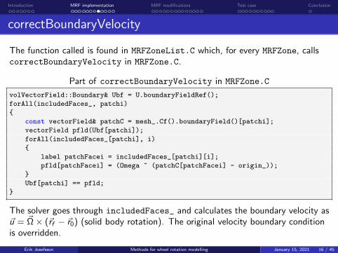
correctBoundaryVelocity
The function called is found in MRFZoneList.C which, for every MRFZone, callscorrectBoundaryVelocity in MRFZone.C.
Part of correctBoundaryVelocity in MRFZone.C
volVectorField::Boundary& Ubf = U.boundaryFieldRef();
forAll(includedFaces_, patchi)
const vectorField& patchC = mesh_.Cf().boundaryField()[patchi];
vectorField pfld(Ubf[patchi]);
forAll(includedFaces_[patchi], i)
label patchFacei = includedFaces_[patchi][i];
pfld[patchFacei] = (Omega ^ (patchC[patchFacei] - origin_));
Ubf[patchi] == pfld;
The solver goes through includedFaces_ and calculates the boundary velocity as~u = ~Ω × (~rf − ~r0) (solid body rotation). The original velocity boundary conditionis overridden.
Erik Josefsson Methods for wheel rotation modelling January 15, 2021 16 / 45

Introduction MRF implementation MRF modifications Test case Conclusion
DDt
Returning to UEqn.H the next influence is from MRF.DDt(U) in MRFZoneList.C.There, for every MRFZone, addCoriolis, found in MRFZone.C, is called.
Part of addCoriolis in MRFZone.C
const labelList& cells = mesh_.cellZones()[cellZoneID_];
vectorField& ddtUc = ddtU.primitiveFieldRef();
const vectorField& Uc = U;
const vector Omega = this->Omega();
forAll(cells, i)
label celli = cells[i];
ddtUc[celli] += (Omega ^ Uc[celli]);
A term ~Ω × ~u is added to the acceleration.
Erik Josefsson Methods for wheel rotation modelling January 15, 2021 17 / 45
Introduction MRF implementation MRF modifications Test case Conclusion
pEqn.H
The next influence from MRF is found in pEqn.H. Firstly MRF.zeroFilter iscalled when calculating phiHbyA, removing the contribution from MRF for thecalculation.
Next MRF.makeRelative(phiHbyA), found in MRFZoneList.C is called. This, inturn, calls makeRelative in MRFZone.C for every MRFZone. The function inMRFZone then calls makeRelativeRhoFlux(geometricOneField(), phi) inMRFZoneTemplates.C.
Erik Josefsson Methods for wheel rotation modelling January 15, 2021 18 / 45

Introduction MRF implementation MRF modifications Test case Conclusion
makeRelativeRhoFlux
Part of makeRelativeRhoFlux in MRFZoneTemplates.C
const surfaceVectorField& Cf = mesh_.Cf();
const surfaceVectorField& Sf = mesh_.Sf();
const vector Omega = omega_->value(mesh_.time().timeOutputValue())*axis_;
const vectorField& Cfi = Cf;
const vectorField& Sfi = Sf;
scalarField& phii = phi.primitiveFieldRef();
// Internal faces
forAll(internalFaces_, i)
label facei = internalFaces_[i];
phii[facei] -= rho[facei]*(Omega ^ (Cfi[facei] - origin_)) & Sfi[facei];
makeRelativeRhoFlux(rho.boundaryField(), phi.boundaryFieldRef());
The relative flux is calculated as φrel = φabs − ρ(~Ω × (~rf − ~r0)
)· ~nf , meaning that
the fluxes on internalFaces_ are the interpolated absolute velocity minus therotation.
Lastly a function with the same name but different parameters is called.Erik Josefsson Methods for wheel rotation modelling January 15, 2021 19 / 45

Introduction MRF implementation MRF modifications Test case Conclusion
makeRelativeRhoFlux
The function called is found in the same file and handles includedFaces_ andexcludedFaces_.
For includedFaces_ the relative flux is simply set to zero. For excludedFaces_the flux is calculated similarly to internalFaces_, as shown below.
Part of makeRelativeRhoFlux in MRFZoneTemplates.C
forAll(excludedFaces_, patchi)
forAll(excludedFaces_[patchi], i)
label patchFacei = excludedFaces_[patchi][i];
phi[patchi][patchFacei] -=
rho[patchi][patchFacei]
* (Omega ^ (Cf.boundaryField()[patchi][patchFacei] - origin_))
& Sf.boundaryField()[patchi][patchFacei];
Erik Josefsson Methods for wheel rotation modelling January 15, 2021 20 / 45

Introduction MRF implementation MRF modifications Test case Conclusion
Motivation
The MRF method will be modified to change how the velocity is calculated in thecells close to the contact patch. When the tyre is deformed the grooves travelparallel to the ground, not along a circular path, at the contact patch.
An option for specifying a z-coordinate in MRFProperties, below which thevelocity will be constrained to the xy -plane, will be added.
Additionally, an option for deactivating the feature (similar to how the MRF zonecan be deactivated) will be added.
Erik Josefsson Methods for wheel rotation modelling January 15, 2021 21 / 45
Introduction MRF implementation MRF modifications Test case Conclusion
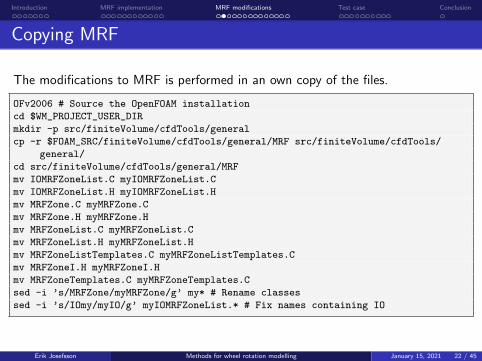
Copying MRF
The modifications to MRF is performed in an own copy of the files.
OFv2006 # Source the OpenFOAM installation
cd $WM_PROJECT_USER_DIRmkdir -p src/finiteVolume/cfdTools/general
cp -r $FOAM_SRC/finiteVolume/cfdTools/general/MRF src/finiteVolume/cfdTools/
general/
cd src/finiteVolume/cfdTools/general/MRF
mv IOMRFZoneList.C myIOMRFZoneList.C
mv IOMRFZoneList.H myIOMRFZoneList.H
mv MRFZone.C myMRFZone.C
mv MRFZone.H myMRFZone.H
mv MRFZoneList.C myMRFZoneList.C
mv MRFZoneList.H myMRFZoneList.H
mv MRFZoneListTemplates.C myMRFZoneListTemplates.C
mv MRFZoneI.H myMRFZoneI.H
mv MRFZoneTemplates.C myMRFZoneTemplates.C
sed -i ’s/MRFZone/myMRFZone/g’ my* # Rename classes
sed -i ’s/IOmy/myIO/g’ myIOMRFZoneList.* # Fix names containing IO
Erik Josefsson Methods for wheel rotation modelling January 15, 2021 22 / 45
Introduction MRF implementation MRF modifications Test case Conclusion
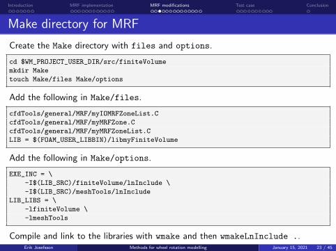
Make directory for MRF
Create the Make directory with files and options.
cd $WM_PROJECT_USER_DIR/src/finiteVolumemkdir Make
touch Make/files Make/options
Add the following in Make/files.
cfdTools/general/MRF/myIOMRFZoneList.C
cfdTools/general/MRF/myMRFZone.C
cfdTools/general/MRF/myMRFZoneList.C
LIB = $(FOAM_USER_LIBBIN)/libmyFiniteVolume
Add the following in Make/options.
EXE_INC = \
-I$(LIB_SRC)/finiteVolume/lnInclude \
-I$(LIB_SRC)/meshTools/lnIncludeLIB_LIBS = \
-lfiniteVolume \
-lmeshTools
Compile and link to the libraries with wmake and then wmakeLnInclude ..Erik Josefsson Methods for wheel rotation modelling January 15, 2021 23 / 45

Introduction MRF implementation MRF modifications Test case Conclusion
Copying simpleFoam
Next a solver is needed to implement the changes. Here simpleFoam will be used.The solver is copied and renamed to mySimpleFoam. Some parts that will not beused is removed.
cd $WM_PROJECT_USER_DIRmkdir -p applications/solvers/incompressible
cp -r $FOAM_APP/solvers/incompressible/simpleFoam applications/solvers/
incompressible/
cd applications/solvers/incompressible
mv simpleFoam mySimpleFoam
cd mySimpleFoam
rm -r overSimpleFoam porousSimpleFoam SRFSimpleFoam
mv simpleFoam.C mySimpleFoam.C
sed -i ’s/simpleFoam/mySimpleFoam/g’ mySimpleFoam.C
Erik Josefsson Methods for wheel rotation modelling January 15, 2021 24 / 45

Introduction MRF implementation MRF modifications Test case Conclusion
Make directory for mySimpleFoam
Make/files is modified to:
mySimpleFoam.C
EXE = $(FOAM_USER_APPBIN)/mySimpleFoam
Make/options is modified to (note that some lines are hidden by ...)
LIB_USER_SRC = $(WM_PROJECT_USER_DIR)/srcEXE_INC = \
-I$(LIB_SRC)/finiteVolume/lnInclude \
...
-I$(LIB_SRC)/transportModels/incompressible/singlePhaseTransportModel \
-I$(LIB_USER_SRC)/finiteVolume/lnIncludeEXE_LIBS = \
-L$(FOAM_USER_LIBBIN) \
-lfiniteVolume \
...
-latmosphericModels \
-lmyFiniteVolume
Compile with wmake to see that everything works.
Erik Josefsson Methods for wheel rotation modelling January 15, 2021 25 / 45

Introduction MRF implementation MRF modifications Test case Conclusion
Modifying mySimpleFoam
In order for mySimpleFoam to use the modified MRF version some code needs tobe modified.
Firstly #include "createMRF.H" found in createFields.H is replaced withmyIOMRFZoneList MRF(mesh);.
Secondly, the header file myIOMRFZoneList.H is added along with the otherlibraries at the beginning of mySimpleFoam.C as shown below.
#include "fvCFD.H"
#include "singlePhaseTransportModel.H"
#include "turbulentTransportModel.H"
#include "simpleControl.H"
#include "fvOptions.H"
#include "myIOMRFZoneList.H"
The solver can now be compiled with wmake.
Erik Josefsson Methods for wheel rotation modelling January 15, 2021 26 / 45
Introduction MRF implementation MRF modifications Test case Conclusion
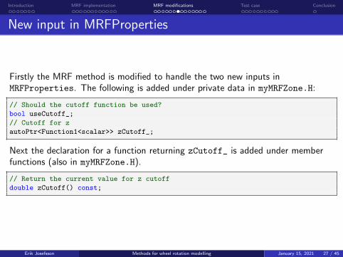
New input in MRFProperties
Firstly the MRF method is modified to handle the two new inputs inMRFProperties. The following is added under private data in myMRFZone.H:
// Should the cutoff function be used?
bool useCutoff_;
// Cutoff for z
autoPtr<Function1<scalar>> zCutoff_;
Next the declaration for a function returning zCutoff_ is added under memberfunctions (also in myMRFZone.H).
// Return the current value for z cutoff
double zCutoff() const;
Erik Josefsson Methods for wheel rotation modelling January 15, 2021 27 / 45

Introduction MRF implementation MRF modifications Test case Conclusion
New input in MRFProperties
Next the constructor in myMRFZone.C is modified.
omega_(Function1<scalar>::New("omega", coeffs_)),
useCutoff_(coeffs_.getOrDefault("useCutoff", false)),
zCutoff_()
if (cellZoneName_ == word::null)
coeffs_.readEntry("cellZone", cellZoneName_);
if (useCutoff_)
Info<< "Using cutoff in MRF zone " << name_ << endl;
zCutoff_ = Function1<scalar>::New("zCutoff", coeffs_);
The definition for the function zCutoff is added right the function Omega.
double Foam::myMRFZone::zCutoff() const
return zCutoff_->value(mesh_.time().timeOutputValue());
Erik Josefsson Methods for wheel rotation modelling January 15, 2021 28 / 45

Introduction MRF implementation MRF modifications Test case Conclusion
correctBoundaryVelocity
Next the code can be modified at the locations were velocities or fluxes arecalculated. In correctBoundaryVelocity (myMRFZone.C) the z-component isset to zero when below the threshold.
const double zCutoff = this->zCutoff();
...
forAll(includedFaces_, patchi)
...
forAll(includedFaces_[patchi], i)
...
if (useCutoff_)
if (patchC[patchFacei].component(2) < zCutoff)
pfld[patchFacei].component(2) = 0;
Ubf[patchi] == pfld;
Erik Josefsson Methods for wheel rotation modelling January 15, 2021 29 / 45

Introduction MRF implementation MRF modifications Test case Conclusion
addCoriolis
addCoriolis in myMRFZone.C is modified to only add the acceleration to cellsabove the threshold.
const vector Omega = this->Omega();
const double zCutoff = this->zCutoff();
const volVectorField& C = mesh_.C();
forAll(cells, i)
label celli = cells[i];
if (useCutoff_)
if (C[celli].component(2) > zCutoff)
ddtUc[celli] += (Omega ^ Uc[celli]);
else
ddtUc[celli] += (Omega ^ Uc[celli]);
Erik Josefsson Methods for wheel rotation modelling January 15, 2021 30 / 45

Introduction MRF implementation MRF modifications Test case Conclusion
makeRelativeRhoFlux
The final modifications are to the functions makeRelativeRhoFlux
(myMRFZoneTemplates.C) which returns the relative fluxes. The first of thesefunctions are modified as shown below.
const double zCutoff = zCutoff_->value(mesh_.time().timeOutputValue());
...
forAll(internalFaces_, i)
label facei = internalFaces_[i];
vector SfiMod = Sfi[facei];
if (useCutoff_)
if (Cfi[facei].component(2) < zCutoff)
SfiMod.component(2) = 0;
phii[facei] -= rho[facei]*(Omega ^ (Cfi[facei] - origin_)) & SfiMod;
Here the z-component of Sf is set to zero before the calculation, which isequivalent to calculating the scalar product and then removing the component.
Erik Josefsson Methods for wheel rotation modelling January 15, 2021 31 / 45

Introduction MRF implementation MRF modifications Test case Conclusion
makeRelativeRhoFlux
In the second makeRelativeRhoFlux nothing is changed for includedFaces_since the relative flux is already set to zero.
For excludedFaces_ the code is modified as shown on the next slide.
Erik Josefsson Methods for wheel rotation modelling January 15, 2021 32 / 45

Introduction MRF implementation MRF modifications Test case Conclusion
makeRelativeRhoFlux
const vector Omega = omega_->value(mesh_.time().timeOutputValue())*axis_;
const double zCutoff = zCutoff_->value(mesh_.time().timeOutputValue());
...
forAll(excludedFaces_, patchi)
forAll(excludedFaces_[patchi], i)
label patchFacei = excludedFaces_[patchi][i];
vector SfMod = Sf.boundaryField()[patchi][patchFacei];
if (useCutoff_)
if (Cf.boundaryField()[patchi][patchFacei].component(2) < zCutoff)
SfMod.component(2) = 0;
phi[patchi][patchFacei] -=
rho[patchi][patchFacei]
* (Omega ^ (Cf.boundaryField()[patchi][patchFacei] - origin_))
& SfMod;
Erik Josefsson Methods for wheel rotation modelling January 15, 2021 33 / 45

Introduction MRF implementation MRF modifications Test case Conclusion
Final compilation
All modifications have now been implemented. Compile with wmake.
If everything compiled as expected, continue to the test case.
Erik Josefsson Methods for wheel rotation modelling January 15, 2021 34 / 45

Introduction MRF implementation MRF modifications Test case Conclusion
Case description
A simplified tyre will by used to illustrate the differences between rotating wall andMRF when simulating grooved tyres. The setup is largely based on the motorbiketutorial.
Geometry properties:
Rotational centre at (0, 0, 0)
Rotational axis aligned with y -axis
Radius of 220 mm
200 mm between ground and rotationalaxis
Flow along x-direction
Erik Josefsson Methods for wheel rotation modelling January 15, 2021 35 / 45

Introduction MRF implementation MRF modifications Test case Conclusion
Mesh
Meshing is performed using snappyHexMesh after constructing a computationaldomain using blockMesh (see included files for details).
Erik Josefsson Methods for wheel rotation modelling January 15, 2021 36 / 45
Introduction MRF implementation MRF modifications Test case Conclusion
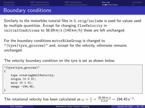
Boundary conditions
Similarly to the motorbike tutorial files in 0.orig/include is used for values usedby multiple quantities. Except for changing flowVelocity ininitialConditions to 38.89 m/s (140 km/h) these are left unchanged.
For the boundary conditions motorBikeGroup is changed to"(tyre|tyre_grooves)" and, except for the velocity, otherwise remainsunchanged.
The velocity boundary condition on the tyre is set as shown below.
"(tyre|tyre_grooves)"
type rotatingWallVelocity;
origin (0 0 0);
axis (0 1 0);
omega -194.45;
The rotational velocity has been calculated as ω = vr = 38.89 m/s
0.2 m = 194.45 s−1.
Erik Josefsson Methods for wheel rotation modelling January 15, 2021 37 / 45

Introduction MRF implementation MRF modifications Test case Conclusion
Results rotating wall
The case can then be solved using simpleFoam.
It can be seen that a realistic velocity is obtained on the tyre surface.
Erik Josefsson Methods for wheel rotation modelling January 15, 2021 38 / 45

Introduction MRF implementation MRF modifications Test case Conclusion
Results rotating wall
However, investigating the velocity in the grooves, rotating wall can not produce arepresentative boundary condition.
Erik Josefsson Methods for wheel rotation modelling January 15, 2021 39 / 45

Introduction MRF implementation MRF modifications Test case Conclusion
Adding MRF in grooves
In order to try capturing the rotation of the grooves the MRFg approach will beused. To enable MRF the file MRFProperties is added in constant with theMRF zone shown below.
MRF1
cellZone MRFZoneSHM;
active yes;
// Fixed patches (by default they ’move’ with the MRF zone)
nonRotatingPatches ();
origin (0 0 0);
axis (0 1 0);
omega -194.45;
Erik Josefsson Methods for wheel rotation modelling January 15, 2021 40 / 45

Introduction MRF implementation MRF modifications Test case Conclusion
Adding MRF in grooves
For this to work a cellZone called MRFZoneSHM needs to be specified. Asindicated by the chosen name this is done in snappyHexMeshDict where thefollowing is added in the geometry section:
MRFZoneSHM
type searchableCylinder;
point1 (0.000 -0.050 0.000);
point2 (0.000 0.050 0.000);
radius 0.220;
Further down, under refinementSurfaces, the following is added, specifyingthat all cells inside the created geometry should be added to MRFZoneSHM.
MRFZoneSHM
level (5 5);
cellZone MRFZoneSHM;
faceZone MRFZoneSHMf;
cellZoneInside inside;
Erik Josefsson Methods for wheel rotation modelling January 15, 2021 41 / 45

Introduction MRF implementation MRF modifications Test case Conclusion
Results MRF
The case can now be meshed and solved just as for rotating wall. A representativevelocity is now obtained in the grooves.
Erik Josefsson Methods for wheel rotation modelling January 15, 2021 42 / 45

Introduction MRF implementation MRF modifications Test case Conclusion
Modified MRF
In order to use the modified MRF method the application in controlDict ischanged to mySimpleFoam. Next, the option for activating the cutoff and thez-coordinate is added to MRFProperties.
MRF1
cellZone MRFZoneSHM;
active yes;
// Fixed patches (by default they ’move’ with the MRF zone)
nonRotatingPatches ();
origin (0 0 0);
axis (0 1 0);
omega -194.45;
useCutoff yes;
zCutoff -0.189;
Erik Josefsson Methods for wheel rotation modelling January 15, 2021 43 / 45
Introduction MRF implementation MRF modifications Test case Conclusion
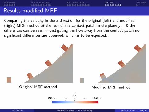
Results modified MRF
Comparing the velocity in the z-direction for the original (left) and modified(right) MRF method at the rear of the contact patch in the plane y = 0 thedifferences can be seen. Investigating the flow away from the contact patch nosignificant differences are observed, which is to be expected.
Original MRF method Modified MRF method
Erik Josefsson Methods for wheel rotation modelling January 15, 2021 44 / 45

Introduction MRF implementation MRF modifications Test case Conclusion
Conclusion
Questions?
Thank you!
Erik Josefsson Methods for wheel rotation modelling January 15, 2021 45 / 45