methods for producing biochar and advanced bio-fuels in
TRANSCRIPT

Methods for Producing Biochar and
Advanced Bio-fuels in Washington State Part 3: Literature Review
Technologies for Product Collection and Refining
May 2012 Publication no. 12-07-034

Publication and Contact Information
This report is available on the Department of Ecology’s website at www.ecy.wa.gov/biblio/1207034.html For more information contact: Waste 2 Resources Program P.O. Box 47600 Olympia, WA 98504-7600
Phone: (360) 407-6900
Washington State Department of Ecology - www.ecy.wa.gov
o Headquarters, Olympia 360-407-6000
o Northwest Regional Office, Bellevue 425-649-7000
o Southwest Regional Office, Olympia 360-407-6300
o Central Regional Office, Yakima 509-575-2490
o Eastern Regional Office, Spokane 509-329-3400 If you need this document in a format for the visually impaired, call the Waste 2 Resources Program at 360-407-6900. Persons with hearing loss can call 711 for Washington Relay Service. Persons with a speech disability can call 877-833-6341.

Methods for Producing Biochar and Advanced Bio-fuels in
Washington State Part 3: Literature Review
Technologies for Product Collection and Refining
by
Manuel Garcia-Perez1, Jesus A. Garcia-Nunez1, Trevor Lewis1, Chad Kruger2, Sylvia Kantor2
1Biological Systems Engineering Department, Washington State University
2Center for Sustaining Agriculture and Natural Resources, Washington State University
This review was conducted under Interagency Agreement C100172 with the Center for Sustaining Agriculture and Natural Resources,
Washington State University

Acknowledgements
Funding for this study is provided by the Washington State Department of Ecology with the intention to
address the growing demand for information on the design of advanced pyrolysis units and systems to
collect, transport and pre-treat feedstock to be processed in these units. The authors wish to thank Mark
Fuchs from the Waste to Resources Program (Washington State Department of Ecology), and David
Sjoding from the WSU Energy program for their continuous support and encouragement. This is the third
of a series of reports exploring the use of biomass pyrolysis to sequester carbon and to produce fuels and
chemicals.
This report is the third of a series of four reports available on the Department of Ecology’s website at:
www.ecy.wa.gov/beyondwaste /organics. The reports are titled: Methods for Producing Biochar and
Advanced Biofuels in Washington State. They are as follows:
• Part 1: Literature Review of Pyrolysis Reactors. This report reviews the technologies that have been
developed for kilns, retorts and pyrolysers. It can be found at:
http://www.ecy.wa.gov/biblio/1107017.html.
• Part 2: Literature Review of the Biomass Supply Chain and Preprocessing Technologies, (From Field
to Pyrolysis Reactor). This report reviews biomass sources, collection, and pretreatment. It can be
found at: http://www.ecy.wa.gov/biblio/1207033.html.
• Part 3: Literature Review of Technologies for Product Collection and Refining. The report describes
technologies and methods for bio-oil products recovery and characterization, biochar activation, bio-
oil refining strategies and regulatory issues related with deployment of pyrolysis technologies. It can
be found at: http://www.ecy.wa.gov/biblio/1207034.html.
• Part 4: Literature Review of Sustainability Goals, Business Models, and Economic Analyses. This
report focuses on the criteria that need to be followed to integrate these technologies into sustainable
business models. The last report presents sustainability criteria and several business models that could
be used to build sustainable enterprises based on biomass pyrolysis technologies. It can be found at:
http://www.ecy.wa.gov/biblio/1207035.html.

Some figures and photos in this report can be seen in color in the online file. Additional project reports
supported by Organic Wastes to Fuel Technology sponsored by Ecology are also available on this web
site. This report is also available at the Washington State University Extension Energy Program library of
bioenergy information at www.pacificbiomass.org.
Citation: Garcia-Perez M., J.A. Garcia-Nunez, T. Lewis, C. E. Kruger, S. Kantor 2011, Methods for
Producing Biochar and Advanced Bio-fuels in Washington State. Part 3: Literature Review of
Technologies for Product Collection and Refining. Third Project Report. Department of Biological
Systems Engineering and the Center for Sustaining Agriculture and Natural Resources, Washington State
University, Pullman, WA, 129 pp.

Beyond Waste Objectives
Turning organic waste into resources, such as compost and bio-fuels, and the recovery of stable carbon
and nutrients along with other products, promotes economic vitality in growing industries, and protects
the environment. This creates robust markets and sustainable jobs in all sectors of the economy, and
facilitates closed-loop materials management where a by-product from one process becomes feedstock for
another with no waste generated.
Disclaimer
The objective of this series of reviews is to describe existing technologies to create clean, non-polluting
pyrolysis units for producing energy, fuels and valuable by-products. The Department of Ecology and
Washington State University provide this publication to the public to help individuals interested in the
develop of a biomass pyrolysis industry to identify suitable technologies for bio-oil condensers, pyrolysis
vapor combustion, removal, cooling, briquetting, pelletization and activation of biochar and bio-oil
refineries. This review also summarizes the analytical techniques needed to characterize bio-oils and
biochars and the permits needed to implement a biomass pyrolysis industry in Washington State. Another
major goal of this project is to identify what new technologies need to be developed or what hurdles need
to be overcome to convert organic waste resources available in Washington State into valuable products.
This review does not represent an endorsement of the processes described and is not intended to exclude
any technology or company offering similar services, that due to time and space limitations was not cited.

Table of Contents
Executive Summary .................................................................................................................. 1 1. Introduction ........................................................................................................................... 2 2. Products Recovery ............................................................................................................... 4
2.1. Bio-oil Condensation ........................................................................................................ 4
2.2. Heat Recovery: Combustion Chambers and Incinerators................................................. 9
2.3. Charcoal Removal and Cooling ......................................................................................12
2.4. Charcoal Briquetting and Pelletization ............................................................................15
3. Product Quality: Bio-Oil Characterization ......................................................................... 17 3.1. Biomass Composition .....................................................................................................17
3.2. Bio-oil Characterization ...................................................................................................17
3.2.1 Fuel and Physico-chemical properties of bio-oils ..........................................................18
3.2.2 Chemical Characterization ............................................................................................19
3.2.3. Solvent extraction ........................................................................................................23
3.2.4. Multiphase structure of bio-oils ....................................................................................28
4. Product Quality: Biochar Characterization ....................................................................... 30 4.1 General Biochar Properties ..............................................................................................31
4.1.1. Surface chemical composition and pore characterization.............................................32
4.2 Potential Pollutants (Polyaromatic hydrocarbons and dioxins compounds) in Biochar .....33
5. Products From Bio-Oil and Biochar .................................................................................. 35 5.1. Bio-oil Products ..............................................................................................................35
5.2. Energy from Bio-oils .......................................................................................................35
5.3. Chemical Products and Transportation Fuels .................................................................37
5.4. Bio-oil Refineries ............................................................................................................38
5.4.1 Bio-oil Refinery Schemes Based on Hydrotreatment ....................................................39
5.4.2 Alternative Bio-oil Refinery Concepts ............................................................................43
5.5. Biochar Products ............................................................................................................48
5.5.1 Household Fuel ............................................................................................................49
5.5.2 Activated Carbon - Activating Biochar ...........................................................................49
5.5.3 Industrial Applications ...................................................................................................54
5.5.4 Carbon Sequestration and Soil Fertility .........................................................................55
5.5.5 Biochar Gasification ......................................................................................................57
6. Regulatory Issues of Current Pyrolysis Technologies ..................................................... 59 6.1. Health and Safety of Handling Bio-oils ............................................................................59

6.2. Health and Safety of Handling Biochar ...........................................................................60
6.3. Environmental Controls, Permitting and Waste Streams .................................................61
7. Conclusion .......................................................................................................................... 64
Appendix A: Bio-oil Condensers ............................................................................................. A-1
Appendix B: Bio-oil Characterization ...................................................................................... B-1
Appendix C: Techniques to Analyse the Chemical Composition of Bio-oils ............................ C-1
Appendix D: Biochar Properties ............................................................................................. D-1
Appendix E: Fuels and Chemicals from Bio-oils ..................................................................... E-1
References .......................................................................................................................... R-16

1
Executive Summary
This is the third report of a serie named “Methods for Producing Biochar and Advanced Bio-fuels in
Washington State”, which describes technologies and methods for products recovery, products
characterization, biochar activation, bio-oil refining strategies and regulatory issues related with
deployment of pyrolysis technologies.
The first section of this report describes technologies for the recovery of bio-oil, biochar, and for
combusting pyrolysis vapors for heat production. Systems for bio-oil collection formed by one, two or
multi-step condensers and for the combustion of pyrolysis vapors are described. Likewise this report
describes some of the most common designs for biochar removal and cooling.
The second and third sections deal with methods to characterize pyrolysis oils and biochars. These
methods are critical to ensure a good products quality. According to the International biochar initiative
(http://www.biochar-international.org/biochar), “biochar is a solid material obtained from the
carbonization of biomass. Biochar may be added to soils with the intention to improve soil functions and
to reduce emissions from biomass that otherwise naturally degrade to greenhouse gases. Biochar also
has appreciable carbon sequestration value. These properties are measurable and verifiable in a
characterization scheme, or in a carbon emission offset protocol”. Thus, biochar characterization is
critical for the commercialization of these products. The chemicals that could be obtained from bio-oil
and the bio-oil refinery concepts that have been evaluated so far are discused in the fifth section.
Options for using biochar in industrial applications (activated carbon and metallurgical application),
household markets, and agricultural and silvacultural applications (soil amendement, fertilizers, and
carbon sequestration) are also discussed in this section.
The final section deals with regulatory issues that need to be taken into account to deploy pyrolysis
technologies. Material safety data sheets (MSDS) for the safe use, handling, storage and transportation of
pyrolysis liquids and biochars as well as the environmental controls, permitting and Waste Streams are
explained.

2
1. Introduction
This report is the third in a series of reports describing technologies needed to build an industry based on
pyrolysis. The first report reviews the evolution of pyrolysis technologies and designs for slow and fast
pyrolysis reactors. The second report discusses equipment needed to build the biomass supply chain
(biomass harvest, densification and transport) and for biomass pre-processing (grinding, screening, and
drying). This report describes designs to recover products (bio-oil condensers, incinerators with heat
recovery, charcoal coolers and charcoal pelletizers) and for product utilization.
A pyrolysis unit typically consists of the equipment for biomass pre-processing, the pyrolysis reactor, and
equipment for downstream processing. Most pyrolysis reactors can be classified as units that produce heat
and biochar (using slow pyrolysis) or units that produce biochar and bio-oils (using fast pyrolysis) (Figure
1).
Figure 1. Strategies for pyrolysis reactors: a) biochar and bio-oil production b) biochar and heat production.
This report is intended to help those interested in developing a biomass pyrolysis industry identify
suitable technologies for bio-oil condensers, pyrolysis vapor combustion, charcoal removal, cooling,
briquetting, pelletization and activation, and bio-oil refineries. It also summarizes analytical techniques
needed to characterize bio-oils and biochars and permits needed to implement a biomass pyrolysis
industry in Washington State.
Methods to characterize bio-oil and biochar products, described in this report, are critical to identify
techniques and instrumentation to control product quality. A review of the potential environmental impact
of these technologies and potential health and safety issues associated with operating these systems is
included to help prevent accidents, reduce the environmental impacts, and create a healthy working
environment. The aim is to alert designers and operators to potential environmental issues so they can
design a process that will meet or exceed standards.
a) b)

3
As stated in the previous reports, pyrolysis technologies with oil recovery will not grow unless a market
for bio-oil is developed. Thus, a review of the potential fuel, chemicals, and other materials that can be
obtained from bio-oils is also presented. Although limited, the review of technologies for bio-oil
refineries provides a general overview of existing options and concepts. Together, the information in
these three reports is fundamental for selecting technologies to create a biomass economy based on
pyrolysis in Washington State.

4
2. Products Recovery
This section describes downstream processing operations for the recovery of bio-oil, biochar, and heat
including bio-oil condensation, combustion chambers and incinerators, and charcoal processing.
2.1. Bio-oil Condensation
A very important aspect of a pyrolysis plant is the bio-oil condensation process. Either single-phase or
multi-phase pyrolysis oils may be collected during condensation depending on the feedstock, reactor and
the condensation system employed. Although scrubbers and heat exchangers have been used by the
petroleum and chemical industries for many years, the knowledge gained cannot be directly extrapolated
to the design of bio-oil condensers due to the presence of acids and the low thermal stability of bio-oils.
Fractional condensation systems were commonly used by the old wood distillation industry, however, few
pyrolysis companies use fractional condensers to separate the water and acids from the pyrolysis oil. In
fact, the modeling and performance of these systems is regaining interest in the academic community
(Westerhof et al 2007, 2011).
The liquid collected from the fast pyrolysis of woody materials is typically a homogeneous liquid referred
to as “bio-oil”. Meanwhile, the liquid collected from the slow pyrolysis of woody materials is formed by
two separated phases sometimes called “decanted oil and pyroligneous acid/aqueous phase”. Lignin
derived compounds are abundant in the decanted oil. Water and polar compounds in the pyroligneous acid
mostly derives from cellulose and hemicelluloses. An important fraction of mono-phenols remains in the
aqueous phase. The formation of tarry products (viscous black sticky oils) occurs when these mono-
phenols continue to react with aldehydes which will gradually increase the yield of decanted oils
(Bunbury 1926).
In order to minimize secondary reactions and maximize oil yields, pyrolysis vapors must be quenched and
condensed very rapidly (Bridgewater and Brown, 2006). Condensers must be designed for easy cleaning
because clogging and tarrying can occur both inside the pipes between the reactor and condenser or in the
condenser itself (Bunbury 1926; Klar and Rule 1925). Condensation can be mitigated by keeping lines
short and temperature over 420 oC (Klar and Rule 1925).

5
Figure 2 shows a configuration of a wagon reactor coupled with a Meyer condenser which typically
collects decanted oil and pyroligneous water. Access ports to clean the vapor lines connecting the reactor
and the retort are important and should be taken into account when designing pyrolysis units.
Figure 2. Cylindrical oven retort arrangement including a Meyer condenser (Source: Bunbury 1926).
Liquids with distinctive chemical compositions can be produced using two or multi-step condensers.
Lower water content and fewer light organic compounds are found in oils condensed at higher
temperatures. As temperature in the first condenser increases (while maintaining the temperature of the
second condenser at 25 oC), the liquid collected downstream will likely be in aqueous phase with high
water content. Condensers of a vacuum pyrolysis plant (built at Jonquiere by the Pyrovac Institute in
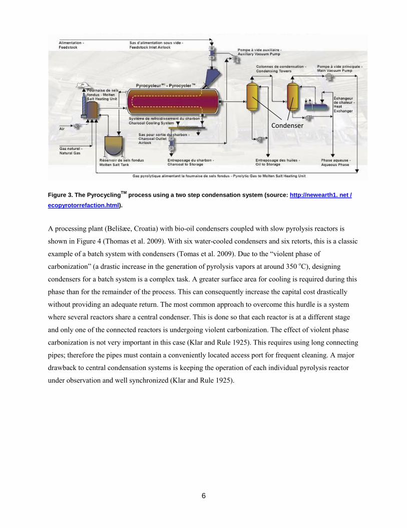
collaboration with Laval University) are shown in Figure 3.
This plant collects a stream rich in heavier molecules (C6>) and an aqueous phase rich in light organic
compounds (C1-C4 oxygenated molecules) and water. The acid content of bio-oils can drastically be
reduced by carefully controlling the temperature of the first condenser (Westerhof et al. 2011). With the
use of bio-oil hydrotreatment, the heavy fraction (C6>) enriched compounds can be transformed into
transportation fuels. The old wood distillation industry targeted the fraction collected in the second
condenser as it is rich in acids that were separated and commercialized as the final product of this
technology.
Condenser Access port to clean
the lines
6
Figure 3. The PyrocyclingTM process using a two step condensation system (source: http://newearth1. net / ecopyrotorrefaction.html).
A processing plant (Belišæe, Croatia) with bio-oil condensers coupled with slow pyrolysis reactors is
shown in Figure 4 (Thomas et al. 2009). With six water-cooled condensers and six retorts, this is a classic
example of a batch system with condensers (Tomas et al. 2009). Due to the “violent phase of
carbonization” (a drastic increase in the generation of pyrolysis vapors at around 350 oC), designing
condensers for a batch system is a complex task. A greater surface area for cooling is required during this
phase than for the remainder of the process. This can consequently increase the capital cost drastically
without providing an adequate return. The most common approach to overcome this hurdle is a system
where several reactors share a central condenser. This is done so that each reactor is at a different stage
and only one of the connected reactors is undergoing violent carbonization. The effect of violent phase
carbonization is not very important in this case (Klar and Rule 1925). This requires using long connecting
pipes; therefore the pipes must contain a conveniently located access port for frequent cleaning. A major
drawback to central condensation systems is keeping the operation of each individual pyrolysis reactor
under observation and well synchronized (Klar and Rule 1925).
Condenser

7
Figure 4. Horizontal retort system for carbonization scheme in Belišæe, Croatia: (R1-6) retorts, (DC1-2) pre-
drying chambers, (CC1-6) charcoal cooling chambers, (1) water-cooled condensers, (2) pyroligneous acid and tar vat, (3) scrubber for residual non-condensable wood gases, (4) scrubber gas stack, (5) flue gas stack. (Source: Tomas et al. 2009).
Bio-oil cooling can be conducted by direct or indirect heat exchangers (Klar and Rule 1925). Table 1
summarizes most bio-oil condensers that have been used in the petroleum industry. Each of the
condensers listed in this table is described in more details in Appendix A. Rapid cooling of the volatile
fraction can be achieved using direct contact condensers (e.g. spray towers). Using cold liquids such as
bio-oils or auxiliary liquids (generally paraffin), vapors are cooled from 500-350 °C to near ambient
temperature.
Direct coolers include single or fractional condensers (multi-step condensers). Fractional condensers
result in two streams with well-defined boiling point distributions. The first step is operated between 40
and 90 oC and the second step is operated between 20 and 30 oC (Westerhof et al. 2011). Fractional
condensers offer an inexpensive way to separate large bio-oil molecules (used for the precursors of
transportation fuels) from small molecules which contribute to undesirable properties of bio-oils. Designs
for direct contact condensers described in this section include the Meyer bubbling condenser, Barbet tab
separator, and scrubbers.
Table 1. Commonly used condensers in pyrolysis units.

8
Characteristics References Direct Contact Condenser Meyer condenser Formed by a hot layer of condensed bio-oil through which vapors
are bubbled. Gases ascend from the lower compartment through a perforated dome. Temperature is kept high enough to minimize condensation of water, prevent condensation of acetic acid and methyl alcohol, and to accelerate reactions of aldehydes and phenols which further produce tarry substances
Bunbury 1926
Barbet tab separator Similar to the Meyer condenser but the pyrolysis vapors heat a lower compartment full of oil before bubbling through the plates
Bunbury 1926
Scrubbers Pyrolysis vapors are put in contact with a liquid spray (an immiscible hydrocarbon, bio-oil or the aqueous phase). Since clogging in the first condensation tower is very intense, it is important to avoid packing. If the temperature in the first condenser is maintained at 80 oC, acetic acid can be almost completely removed
Bunbury 1926 Oasmaa et al. 2005, Westerhof et al. 2007, 2011 Klar and Rule 1925, San Miguel et al. 2011
Reactive Scrubbers Scrubber in which a chemical reactant (typically an alcohol) is added as cooling liquid to stabilize bio-oil. Reactive species concentration is reduced.
Hilten et al. 2010
Indirect Contact Heat Exchangers Tube and shell It is customary to first pass the pyrolytic gas and vapors through an
easily cleanable section given the tendency of pyrolysis vapors to form incrustations during the condensation process. The most common design described in the literature suggests condensing the oils inside the tube while allowing the cooling water or air to circulate around the tubes. In order to facilitate cleaning and to avoid slagging etc., the length of the tubes in these exchangers should be limited keeping the cooling path relatively short.
Klar and Rule 1925; Bunbury et al. 1926; Veitch 1907
Coil Condenser In coil condensers, the gaseous mixture passes through a single tube which, in order to afford an equal area of cooling, must be correspondingly longer. Rather than a coil wound into a spiral, the tube forming the coil is made up of a number of inclined and superimposed straight tubes connected by bends or elbows. The connecting elbows are located outside the water tank where they can be removed in order to clean the condensing tubes.
Klar and Rule 1925
Indirect cooling with water or air is also used in bio-oil condensation. The heat transfer area using air is
typically 15 times larger than using water due to the difference in the heat transfer coefficient between air
and water. Air cooling should be reserved for situations where obtaining clean cooling water is difficult
(e.g. operating mobile units).
Liquid gas separators: These systems are used after the condensers. The condensate from the tubes is
collected in the bottom chamber. An outlet in this chamber leads to the gas trap, or gas separator. The
device used to separate the liquid condensed from the non-condensable gases in the old wood distillation
industry is seen in Figure 5. These vessels were typically small (Bunbury 1926).

9
Figure 5. Separation devices for the condensable fraction and pyrolysis gases (Source: (Klar and Rule 1925).
Other systems that may be added for downstream separation of pyrolysis products (aerosols) include:
electrostatic precipitators (ESP), venturi scrubbers, or rotary demisters. Electrostatic precipitators have
been used more often in the laboratory than in the industry despite their efficiency in aerosol removal
(Bunbury 1926). Compared to the energy consumption of venturi scrubbers, which consume between 1.5
– 6 kWh/1000 m3, electrostatic precipitators are very efficient with energy consumption of 0.2 – 0.4
kWh/1000 m3 (San Miguel et al. 2011).
2.2. Heat Recovery: Combustion Chambers and Incinerators
Given that condensation of bio-oils will not be economically viable until bio-oil refining installations are
developed, currently, the most viable approach appears to be heat recovery through combustion of
pyrolysis vapors to produce steam or electricity. Compared to traditional systems, heat recovery reduces
the environmental impact of pyrolysis reactors and recovers the energy contained in pyrolysis vapors. A
pyrolysis plant equipped with a heat recovery system is shown in Figures 6 and 7 and a continuous batch
process system equipped with heat recovery where the gases and vapors are fed into the combustion
chamber is shown in Figure 8.
Gas + liquid
Gas
Liquid
Gas + liquid
Gas

10
Figure 6. A green waste pyrolysis plant schematic diagram for the production of biochar (Weaver et al. 2010)
(source: http://ieabioenergy.com/DocSet.aspx?id=6735).
Figure 7. Green waste pyrolysis plant (120 kg/h) with heat recovery (Weaver et al. 2010) (source: http://ieabioenergy.com/DocSet.aspx?id=6735).
A centralized combustion system for pyrolysis vapors is advantageous when using batch pyrolysis
reactors (Figure 8) (Murcia et al. 2008). The company CIRAD has been developing and installing
afterburners for batch pyrolysis reactors since 1993. The system, called a CML process (Figure 8), is
made up of a depollution system which incinerates waste gases without heat recovery and is linked to 12
production kilns. This system does not produce vapor or electricity from the energy contained in the
pyrolysis vapors.

11
Figure 8. Several batch pyrolysis reactors linked to an after burner known as a CML process (Source: http://www.drveniugljen.hr/assets/files/ prezentacije/06_Christian_Bedrossian.pdf).
The energy contained in pyrolysis vapors can be recovered by a system with heat recovery boilers (Figure
9) to produce hot gas, steam, or electricity. This can be done easily if the pyrolysis process is continuous.
Figure 9. The steam produced by this auger pyrolysis unit with a thermal oxidizer can be used to generate electricity. (Source: http://www.internationaltechcorp.org/IT-info.htm#convert).
Although little information on the combustion of pyrolysis vapors is found in the literature, Figure 10
shows one scheme with information on the temperature profile achieved in a thermal oxidizer chamber
using pyrolysis vapors. Combustion of pyrolysis vapors (as is the case with the combustion of syngas) is
expected to be much cleaner than the combustion of biomass itself but more studies are needed to
characterize combustion gases derived from pyrolysis vapors.

12
Figure 10. A flameless oxidation in the combustion chamber known as FloxR (Weaver et al. 2010) (source: http://ieabioenergy.com/DocSet.aspx?id=6735).
2.3. Charcoal Removal and Cooling
Systems for charcoal removal and cooling depend on the shape and size of the biochar produced and the
design of the pyrolysis reactor. Biochar is produced in three different forms: small particles, chunks, or
logs. In most ancient carbonization systems, char was allowed to cool inside the reactor and then was
manually collected.
Cyclones (Figure 11) are typically used in fluidized and circulating bed pyrolysis reactors to separate the
particles from the pyrolysis vapors. This is the simplest and cheapest equipment available, but only
particles greater than 10 µm can be separated efficiently with this technology. However, due to attrition,
fluidized bed reactors usually produce some amount of char fines (diameter smaller than 1 µm) which are
difficult to separate by cyclones and find their way to the condensers (Di Benedetto and Salatino 1998;
San Miguel et al. 2011; Scala and Chirone 2006).
Hot filtration is one of the most effective methods to remove particles from hot gases (Figure 12)
(Ahmadi and Smith 2002; Dittler and Kasper 1999). Higher solid separation efficiencies (particularly with
particles < 10 µm) can be achieved with ceramic filters. These systems require higher maintenance and
operation costs and result in greater pressure drops. However, due to secondary reactions that take place
between the vapor and the solid layer collected in the filter, the installation of hot gas filtration
technologies reportedly reduces bio-oil yields (Ito et al. 1998; Schaill et al. 1996).

13
Figure 11. Cyclones used to separate biochar (Source: San Miguel et al. 2011).
Figure 12. Example of hot filter to remove particles from hot gases (Ahmadi and Smith 2002).
Hoekstra et al. (2009) developed a filtration system for in-situ removal of char/ash from the pyrolysis
vapors in a fluidized bed reactor (Figure 13). By integrating the filter with the fluidized bed, some of the
problems associated with the increase in pressure drop in mesh filters over time are eliminated. Pores
located on the outside surface of the filter retain the particles (char, sand). Even with a reused filter, good
process stability concerning temperature and pressure drop across the hot gas vapor was achieved during
a two-hour run. Apart from some deposits formed on the metal wire and small 1 μm particles that slip
through the filter, the inside of the filter remains clean (Hoekstra et al. 2009).

14
Figure 13. Continuous bench scale reactor setup (Hoakstra et al. 2009).
Separation of particles with diameters close to 1 mm in auger reactors and other moving bed reactors is
conducted by gravity. An auger cooler coupled with the pyrolysis reactor cools the biochar in continuous
systems using chips and powdery materials (Figure 14 and 15). This charcoal removal system can be used
in combination with most pyrolysis reactors that handle chips and small particles (e.g. augers, multiple
hearth kilns and rotary drums).
Figure 14. Charcoal cooler for a continuous auger reactor (Miles 2010).
Charcoal cooler

15
Figure 15. Charcoal cooling system in vacuum pyrolysis plant (Source: Group Pyrovac).
2.4. Charcoal Briquetting and Pelletization
Transportation of biochar must be done when it is in pellet or briquette form as it creates a safety and
health hazard if it is transported in powdery form. A “briquette” is the material obtained by mixing
powdered biochar with a binder. Biochar in the form of fines, binder, and filler are the raw materials for
briquettes. The binder is made up of molasses, tar or starch. The most costly component of briquettes is
the binder (typically starch). It must be able to resist bacterial attack and fermentation during storage.
Filler is added to reduce costs and may also help control the burning rate of the briquette. Filler must cost
less than biochar, be free of objectionable odor while burning, and must not be abrasive to the machinery.
Heated gases can be utilized for drying briquettes by simply attaching a briquetting unit to the
carbonization plant. The steps shown in Figure 16 are typical of a 1 ton/hr briquetting plant and include
the following dedicated equipment: hammer mill, paddle mixer, vertical fluxer, starch feeder or pump,
briquette press with paddle feeder, bagging machine, boiler, conveyors and a building (Toole et al.
1961).1
1 Briquetting charcoal can be found in more detail at http://www.fao.org/docrep/x5328e/ x5328e0c.htm#Top OfPage
(date accessed: Nov. 13, 2010).
Charcoal cooler

16
Figure 16. Charcoal briquette commercial process manufacturing flow diagram (Toole et al. 1961).
Emrich (1985) described equipment suitable for a medium size plant with a briquetting capacity of 1,000
to 5,000 tons/year (3-15 t of biochar per day or 12-60 t biomass/day). These plants include: 1)
preparation, where the charcoal is accumulated and fed into a pulverizer by a precise feeder; 2) crushing,
where a hammer mill is used to properly size the material; 3) mixing, which provides extra retention time
to guarantee thorough blending with the binder, filler additives and etc.; 4) forming: where roller type
presses are used and may be adjusted to different speeds and pressures; and 5) drying (Emrich 1985).
For heat and biochar production (typical application of slow pyrolysis processes) it is advantageous to
pelletize or briquette the feedstock before pyrolysis. The shape and consistency of pellets and briquettes
are partially conserved during pyrolysis. The use of binding agents, fillers and pelletizing biochar is
expensive compared with making pellets at the front end. For fast pyrolysis to maximize oil production,
small biomass particles must be pyrolysed and biochar pellets or briquettes produced afterward (Figure
16). The process shown in Figure 16 is used to produce biochar briquettes from lump charcoal produced
from slow pyrolysis reactors.

17
3. Product Quality: Bio-Oil Characterization
Quality assurance can be achieved by subcontracting a centralized lab (suitable for small pyrolysis plants)
or in the plant’s own laboratory (suitable for large pyrolysis plants) (Hess et al. 2006). Depending on the
biomass composition, the pyrolysis process, and the condensation conditions, the liquid product (bio-oil)
may be formed by two or more phases (Oasmaa and Peacoke 2001). Fast pyrolysis produces a single
phase bio-oil, where as slow pyrolysis produces a two phase bio-oil.
Oasmaa et al. (2009) published a review on bio-oil quality control and standards. Presently there are no
recognized national or international standards for the specifications of bio-oil (Oasmaa and Peacocke
2001). However, the International Energy Association (IEA), Task 34 (2010 – 2012) addresses standards
development within ASTM (Oasmaa et al 2009). Within the International Energy Association (IEA), the
first set of standards was promulgated for bio-oil through the Pyrolysis Activity under Task XIII. The
European biomass community is undergoing a lot of activity to develop protocols and standard methods
for measuring properties of bio-oil. In order to provide credibility to measurements of final specifications
and methods, an organization such as the American Society for Testing and Materials (ASTM) also needs
to be involved. A pyrolysis oil standard initiative for bio-oils started in 2007 within D02 Petroleum
Products and Lubricants Committee. End-use equipment manufacturers must also be involved in the
establishment of specifications (Ringer et al. 2006).
3.1. Biomass Composition
The quality, quantity, properties, and chemical composition of biochar and bio-oil are dependent on raw
materials, or biomass. Hence, insight into the biomass composition is very important for the outcome of
biomass pyrolysis. Biomass composition is also important to develop tactics to favor reactions that give
desirable product and limit reactions that produces undesirable outcomes. Biomass is composed primarily
of cellulose, hemi-cellulose and lignin with a small fraction of light aliphatics and aromatics (extractives)
and mineral matter (ash).
3.2. Bio-oil Characterization
Depending on the purpose of the analysis, bio-oils can be characterized and classified according to: their
fuel properties, their physical appareance, their chemical composition, their solubility on targeted
solvents, etc. In this section we will group the techniques used for bio-oil characterization into four main
categories: fuel properties, chemical composition, solvent extraction and multiphase structure.

18
During fast pyrolysis, biomass generally is converted into the following: 8-15 wt. % small organic
compounds (mostly, hydroxyacetaldehyde, acetol, acetic acid, formic acid and methanol); 5-10 wt. %
mono phenols and furans; 6-15 wt. % hydrolysable sugars; 6-15 wt. % lignin oligomers; 10-15 wt. %
water; and around 20 wt. % unknown fraction (likely products from cellulose and cross linked reactions,
which may be the source of branched paraffins when the bio-oil is hydrotreated). The remaining biomass
(15-25 wt. %) is either converted into gases or charcoal.
The yield of bio-oil is typically 60-75 wt. % of the original biomass.The bio-oil that is collected consists
of the water, light fractions, mono phenols, furans, fermentable sugars, lignin oligomers and the unknown
heavy fraction (likely cross linked sugars). Bio-oil generally exhibits viscosity of 35-53 cSt at 40 °C,
contains a small amount of ash 0.04-0.24 wt. %, and is acidic (pH: 2.5-3.4). Bio-oils have complex
multiphase systems due to the presence of char particles, waxy materials, aqueous droplets, and micelles
formed from heavy compounds, (Garcia-Perez 2006; Elliott 2001; Frantini 2006; Kang et al. 2006).
3.2.1 Fuel and Physico-chemical properties of bio-oils Compared to petroleum fuel, bio-oil contains high oxygen content (45-50%) in the form of ester, ether,
carbonyl, carboxyl and hydroxyl groups. The primary reason for the difference in properties and behavior
between hydrocarbon fuels and biomass pyrolysis oil is the polar nature of bio-oils caused by the presence
of oxygenated functional groups. The elemental composition of bio-oil (CHNSO content) is similar to that
of the biomass from which it was derived (Mohan and Steele 2006). Table 2 presents properties and
characteristics of wood-derived bio-oils.
Table 2. Properties and characteristics of wood-derived crude bio-oil (Bridgwater 2003; Mohan et al. 2006).
Fuel specifications establish a balance between engine requirements and the cost and availability of the
fuel. An entire set of combustion characteristics must be fulfilled in order to label a substance as a fuel.
The American Society for Testing and Materials (ASTM) typically serves as an international organization
that develops and publishes voluntary concensus technical standards for a wide range of materials and
methods. Oasmaa et al (2009) reviewed the status of the development of bio-oil standards within ASTM.
A lack of specification for fuel applications is a handicap facing both producers and users of pyrolysis
Property Characteristics Appearance From almost black or dark red-brown to dark green Miscibility Water content from ~15 wt % to ~30 – 50 wt % before phase separation occurs.
Miscible with polar solvents (methanol, acetone, etc.) but almost totally immiscible with petroleum-derived fuels.
Density Approximately 1.2 kg/L (compared to ~0.85 kg/L for light fuel oil). Viscosity Viscosity varies from 25 cSt to 1000 cSt (measured at 40°C). Distillation Cannot be completely vaporized. Above 100 oC, rapidly reacts and eventually
produces a solid residue ~50 wt % of the original liquid. Stability Chemically unstable. Store liquid at or below room temperature.

19
oils. In-depth summaries of the potential for using biomass derived fuels on performance and durability of
gas turbine systems and boilers is provided by Moses (1994), Diebold et al. (1999) and Drennan (1994),
Oasmaa et al (2009). Accuracy of physical analysis is generally good with regard to homogeneous
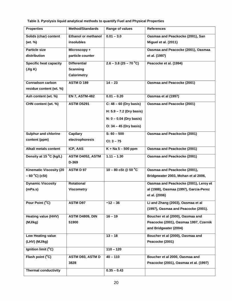
pyrolysis liquids. However, results for heterogeneous liquids may be inconsistent. Table 3 lists several
methods to determine bio-oil physico-chemical properties.
3.2.2 Chemical Characterization Garcia-Perez et al. (2007) describe bio-oil composition in chemical families depending on the boiling
point or the cracking temperature at which the compounds forming the family are evaporated. The very
volatile compounds with boiling point below 100 oC (Family 1) are usually disregarded in most papers
because the gas chromatography-mass spectroscopy (GC/MS) chromatograms are commonly recorded
after solvent and water have been eluted to avoid damaging the MS detector. This family is formed
mostly by hydroxyacateldehyde, formic acid, and methanol and can be easily characterized by GC-FID
using heavier solvents. Family 2 is formed by compounds with boiling points comparable to water
(mostly acetic acid and acetol). The organics in this family can be quantified by GC/MS and the water by
Karl Fischer titration. Family 3 is mainly formed by mono-phenols and mono-furans with boiling points
between 100 and 200 oC. This fraction is typically quantified by GC/MS. Sugars are heavier and as such
only the levoglucosan can be analysed by GC/MS without derivatization. The sugars in the oil (Family 4)
can be classified in hydrolysable sugars and non-hydrolizable sugars. The hydrolysable sugars can be
quantified by ion exchange chromatography after hydrolysis with sulfuric acid. The non-hydrolysable
sugars are a large fraction which is currently poorly understood. Lignin oligomeric materials are typically
quantified by cold water precipitation (Family 5). Up to now there is little agreement and standard
techniques and method to characterize the chemical composition of bio-oils. Techniques to determine the
chemical composition of bio-oils are summarized in Table 4.
20
Table 3. Pyrolysis liquid analytical methods to quantify Fuel and Physical Properties
Properties Method/Standards Range of values References
Solids (char) content (wt. %)
Ethanol or methanol insolubles
0.01 – 3.0 Oasmaa and Peackocke (2001), San Miguel et al. (2011)
Particle size distribution
Microscopy + particle counter
Oasmaa and Peacocke (2001), Oasmaa et al. (1997)
Specific heat capacity
(J/g K)
Differential
Scanning Calorimetry
2.6 – 3.8 (25 – 70 oC) Peacocke et al. (1994)
Conradson carbon residue content (wt. %)
ASTM D 189 14 – 23 Oasmaa and Peacocke (2001)
Ash content (wt. %) EN 7, ASTM-482 0.01 – 0.20 Oasmaa et al (1997)
CHN content (wt. %) ASTM D5291 C: 48 – 60 (Dry basis)
H: 5.9 – 7.2 (Dry basis)
N: 0 – 0.04 (Dry basis)
O: 34 – 45 (Dry basis)
Oasmaa and Peacocke (2001)
Sulphur and chlorine content (ppm)
Capilary electrophoresis
S: 60 – 500
Cl: 3 – 75
Oasmaa and Peackocke (2001)
Alkali metals content ICP, AAS K + Na 5 – 500 ppm Oasmaa and Peackocke (2001)
Density at 15 oC (kg/L) ASTM D4052, ASTM
D-369
1.11 – 1.30 Oasmaa and Peackocke (2001)
Kinematic Viscosity (20
– 60 oC) (cSt)
ASTM D 97 10 – 80 cSt @ 50 oC Oasmaa and Peackocke (2001),
Bridgewater 2003, Mohan et al 2006,
Dynamic Viscosity (mPa.s)
Rotational Viscometry
Oasmaa and Peackocke (2001), Leroy et al (1988), Oasmaa (1997), Garcia-Perez et al. (2006)
Pour Point (oC) ASTM D97 −12 – 36 Li and Zhang (2003), Oasmaa et al
(1997), Oasmaa and Peacocke (2001).
Heating value (HHV) (MJ/kg)
ASTM D4809, DIN 51900
16 – 19 Boucher et al (2000), Oasmaa and Peacocke (2001), Oasmaa 1997, Czernik and Bridgwater (2004)
Low Heating value (LHV) (MJ/kg)
13 – 18 Boucher et al (2000), Oasmaa and Peacocke (2001)
Ignition limit (oC) 110 – 120
Flash point (oC) ASTM D93, ASTM D
3828
40 – 110 Boucher et al 2000, Oasmaa and
Peacocke (2001), Oasmaa et al. (1997)
Thermal conductivity 0.35 – 0.43

21
Properties Method/Standards Range of values References
(W/mK)
pH pH meter 2.0 – 3.7 Oasmaa and Peackocke (2001)
Thermal stability (Aging process)
FTIR method, following viscosity changes. Tests at 80 oC for 24 hours and at 40 oC for 1 week.
Scholze and Meier (2001), Oasmaa and Peacocke (2001), Oasmaa et al (1997, 2001, 2003), Polk & Phingbohippakkiya
(1981), Czernik et al (1994), Oasmaa and Czernik (1999), Mohan and Steele 2006,
Diebold et al. (1999).
Total Acid Number
(TAN)
ASTM D664, D3339
ASTM D974, ASTM D664
Molte et al. (2010), Oasmaa et al (2010)
Distillation Cannot be completely vaporized.
Bridgwater 2003, Mohan et al 2006

22
Table 4. Quantification of Bio-oil Compounds, chemical families and functional groups
Property, Fraction or Compound Analytical Method or Standard References
Macro chemical families Deconvolution of DTG curves Garcia-Perez et al. (2007)
Molecular weight distribution GPC, MALDI-TOF-MS, LDI-TOF-MS, and Py-FIMS
Anderson et al (2000), Garcia-Perez et al (2006), Vuorien et al (1998), Scholze et al. (2001), Hoekstra et al (2011),
Bayarbach et al. (2006)
Water content KF Titration (ASTM 203, 1744) Garcia-Perez et al (2007), Oasmaa et al (1997), and Oasmaa and Peacocke (2001)
Mono phenols and furans GC-MS Ingram et al (2008), and Song et al.
(2009)
Carboxylic, fatty and resin acids GC/MS Pakdel et al (1987, 1991, 1994), Branca
et al. (2003) , Pimenta et al (1998)
Volatile fraction (classification of volatile fraction in chemical families)
2D-GC-TOF-MS Fullana et al. (2005), Marsman et al (2008)
Lignin oligomers (pyrolytic lignin) Cold water precipitation Bayarbach and Meier (2009), Scholze
and Meier (2001 a, b), Windt et al (2009), Bayarbach et al (2006), Scholze and Meier (2002).
Lignin oligomers of low molecular
weight
Cold water precipitation
followed by washing with CH2Cl2
Bayarbach and Meier (2009), Scholze
and Meier (2001 a, b), Windt et al (2009), Bayarbach et al (2006), Scholze and Meier (2002).
Chemical structure of lignin oligomers
Titration with tri-sulfate, FTIR, SEC, MALDI-TOF-MS, LADO-
TOF-MS, and Py-FIMS
Bayarbach et al (2006), Scholze and Meier (2001)
Methoxyl groups in pyrolytic lignin Titration with trisulfate Scholze and Meier (2001)
Hydrolyzable sugars soluble in water (mainly levoglucosan and cellobuiosan)
Hydrolysis of water soluble fraction followed by ion exchange chromatography or
HPLC.
Lian et al. (2010) and Mohan et al. (2006)
Total content of sugars Brix determination (Anton Paar DMA 4500 hydrometer)
Oasmaa and Kuoppala (2008)
Elemental analysis (CHN-O) ASTM D 5291 Anja Oasmaa and Peacocke (2001) and Acikgoz and Kockar (2009)
Overall functional groups FTIR Lievens et al (2011), Acikgoz et al (2009), Scholze and Meier (2001)

23
Property, Fraction or Compound Analytical Method or Standard References
Carbonyl carbons, total aromatic carbons, carbohydrate-type
carbons,methoxy- or hydroxyl- bound carbons: primary, secondary, tertiary and most
quaternary alkyl carbons.
13 C-NMR Ingram et al 2008, Mullen et al, 2009, Song et al. 2009
Aliphatic protons, aliphatic hydroxyls, protons located alpha to ketone, aldehydes or carbonyl
groups, methoxy, -CH2O-, - CHO-, CHO groups, phenolic –OH,
nonconjugated olefinic protons, olefinic protins, and double bonds conjugated to carbonyls
1 H-NMR Acikgoz and Kockar (2009) and Ingram et al. (2008)
Due to bio-oil’s diverse chemical functionalities and wide range of molecular weights and boiling points,
a combination of several analytical techniques is needed for global analysis of pyrolysis liquids including:
GC-MS (volatile compounds), high performance liquid chromatography (HPLC), HPLC/electrospray MS
(nonvolatile compounds), Fourier transform infrared (FTIR) spectroscopy, gel permeation
chromatography (GPC) (molecular weight distributions), UV, UV-Fluorescence, nuclear magnetic
resonance (NMR), thermogravimetry, and solvent extraction. Several of these techniques are discussed in
Appendix C.2
3.2.3. Solvent extraction Solvent extraction is another method used to characterize bio-oils (Mohan et al. 2006). Properly selecting
solvents is the first step in developing a solvent extraction strategy. The degree of polarity significantly
affects the solubility of pyrolysis liquids in solvents other than water (Oasmaa and Peacocke 2001).
Alcohols, like ethanol and methanol, are good solvents for highly polar white wood and straw pyrolysis
liquids. Hydrocarbons like hexane, diesel fuels and polyolefins do not dissolve with wood pyrolysis
liquids but can be useful to adsorb extractive derived compounds such as fats, waxes, resins, terpenes, and
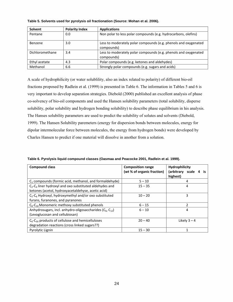
essential oils. Table 5 shows several solvents used to extract bio-oil fractions and their polarity indices.
2 For further discussion of this topic see Diebold et al. 1999, Meier et al. 1999, and Oasmaa 1999.
24
Table 5. Solvents used for pyrolysis oil fractionation (Source: Mohan et al. 2006).
Solvent Polarity Index Applications Pentane 0.0 Non polar to less polar compounds (e.g. hydrocarbons, olefins)
Benzene 3.0 Less to moderately polar compounds (e.g. phenols and oxygenated compounds)
Dichloromethane 3.4 Less to moderately polar compounds (e.g. phenols and oxygenated compounds)
Ethyl acetate 4.3 Polar compounds (e.g. ketones and aldehydes) Methanol 6.6 Strongly polar compounds (e.g. sugars and acids)
A scale of hydrophilicity (or water solublility, also an index related to polarity) of different bio-oil
fractions proposed by Radlein et al. (1999) is presented in Table 6. The information in Tables 5 and 6 is
very important to develop separation strategies. Diebold (2000) published an excellent analysis of phase
co-solvency of bio-oil components and used the Hansen solubility parameters (total solubility, disperse
solubility, polar solubility and hydrogen bonding solubility) to describe phase equilibrium in his analysis.
The Hanses solubility parameters are used to predict the solubility of solutes and solvents (Diebold,
1999). The Hansen Solubility paremeters (energy for dispersion bonds between molecules, energy for
dipolar intermolecular force between molecules, the energy from hydrogen bonds) were developed by
Charles Hansen to predict if one material will dissolve in another from a solution.
Table 6. Pyrolysis liquid compound classes (Oasmaa and Peacocke 2001, Radlein et al. 1999).
Compound class Composition range (wt % of organic fraction)
Hydrophilicity (arbitrary scale 4 is highest)
C1 compounds (formic acid, methanol, and formaldehyde) 5 – 10 4 C2-C4 liner hydroxyl and oxo substituted aldehydes and ketones (acetol, hydroxyacetaldehyse, acetic acid)
15 – 35 4
C5-C6 Hydroxyl, hydroxymethyl and/or oxo substituted furans, furanones, and pyranones
10 – 20 3
C6-C10 Monomeric methoxy substituted phenols 6 – 15 2 Anhydrosugars, incl. anhydro-oligosaccharides (C6, C12) (Levoglucosan and cellubiosan)
6 – 10 4
C6-C30 products of cellulose and hemicelluloses degradation reactions (cross linked sugars??)
20 – 40 Likely 3 – 4
Pyrolytic Lignin 15 – 30 1

25
Several solvent extraction techniques and their potential uses for bio-oil characterization are presented
below.
Water Separation: By simply adding water to bio-oil it can easily be separated into water soluble and
organic fractions (Oasmaa and Peacocke 2001). The heavy, mainly lignin-derived fraction (but also
containing water and some sugars) separates out from the aqueous fraction during phase separation. Phase
separation typically occurs by adding water until the liquid is about 25 wt. % water (Peacocke et al.
1994). Carbohydrate-derived compounds (light compounds, hydrolysable sugars and cross linked sugars)
are abundant in the water-soluble fraction. Brown et al. (2009) studied the effect of water temperature and
water/bio-oil ratio on yield of decanted oil proving that the fraction of decanted oil obtained was
dependant on the water/bio-oil ratio (Figure 17). Usually 25 – 30 wt. % of the whole bio-oil is comprised
of the “lignin-rich” fraction (or decanted oil).
Figure 17. The amount of decanted oil is affected by temperature and the water/bio-oil ratio (Brown et al. 2009).
A phase diagram for a pyrolysis liquid/water system can be used to estimate the content of water and
organics in the decanted oil and aqueous phases (Figure 18) (Oasmaa and Czernik 1999).

26
Figure 18. Phase diagram of biomass pyrolysis oil/water (Oasmaa and Czernik 1999).
Song et al. (2009) explored the use of aqueous salt solutions for bio-oil extraction. The use of salts
is an effective method to improve the separation of bio-oil. Ethyl acetate can be used to further extract
the water soluble fraction. Silipa et al. (1998) proposed a scheme for the separation of bio-oils using water
precipitation followed by the extraction of the water soluble fraction with ethyl acetate and the washing of
the water insoluble fraction with dichloromethane (Figure 19).

27
Figure 19. The separation and characterization of biomass-based flash pyrolysis bio-oil using solvent fractionation (Source: Spila et al. 1998, http://www.biocoup.com/index.php?id=144).
If the bio-oil contains large amounts of wood extractives, it is recommended to use an extraction with n-
hexane (Garcia-Perez et al. 2007, Sipila et al. 1998). The use of ethyl acetate was developed for the
extraction of mono and oligo-phenols. A fractionation method developed by National Renewable Energy
Lab (NREL) is shown in Figure 20 (Chum et al. 1989).
Fractional distillation: Fractional distillation of bio-oil is impossible due to the presence of oligomeric
sugars (hydrolyzable and cross-linked) and lignin derivatives. Due to this fact, bio-oil differs from most
grades of petroleum. The chemical composition of the oils obtained from vacuum distillation was
characterized by Schirmer et al. (1984). The distillation characteristics of the fresh bio-oil, studied by
Adjaye et al. (1992), showed that using 174 Pa at 200 oC produced the maximum amount of organic
distillate. Aromatic, aliphatic and naphthenic hydrocarbons, as well as oxygenated compounds such as
furans, alcohols, acids, ethers, aldehydes, ketones and phenols made up this distillate fraction (Adjaye et
al. 1992).

28
Figure 20. Bio-oil fractionation method developed by NREL (Chum et al. 1989).
3.2.4. Multiphase structure of bio-oils Liquid products of pyrolysis may be formed by two or more phases depending on the composition of the
feedstock, and pyrolysis and condensation conditions (Oasmaa and Peacocke 2001). While slow pyrolysis
of woody biomass usually results in a two phase bio-oil (decanted oil and pyroligneous water), fast
pyrolysis of the same feedstock typically results in a single phase bio-oil. An extra phase (called the upper
layer or extractive rich layer) is the result of the presence of extractive in the feedstock (Garcia-Perez et
al. 2006, Oasmaa et al. 2003, Oasmaa and Peacocke 2001). Table 7 summarizes studies on the multi-
phase structure of bio-oils.
Whole Oil
Dissolve in EtOAc (1:1) and Filtration
Upon Standing
Char
EtOAc Soluble EtOAc insoluble (Most of the water and water very polar compounds)
Water with very polar compounds
Wash with water
Organic Phase
Organic Phase
Extraction with NaHCO3, 5 mass %
Aqueous Phase
Aqueous Phase
EAOAc soluble Phenols and Neutrals (PIN)
Aqueous Layer (Organic Acids) Acidity with H3PO4 (pH 2)
Saturating with NaCl
Water Soluble (Aqueous)
Acids (Organics)

29
Table 7. Multi-phase structure of bio-oils
Property, Fraction or Compound Method References
Structure (phases) in the micrometer scale
Optical microscopy with polarized and non-polarized light
Garcia-Perez et al (2006), Oasmaa et al 2003, Oasmaa and Peacocke (2001)
Effect of temperatures on bio-oil structural features
Microscopic analyses conducted on got stages
Ba et al (2004), Garcia-Perez et al (2006), Oasmaa et al (2003)
Melting of waxy materials (derived
from extractives)
Optical Microscopy with
polarized light, CPM, NIR scattering technique, rheology and DSC
Garcia-Perez et al. (2006), Paso et al
(2009), Nolte et al (2010)
Nano-structure (pyrolytic lignins) Dynamic rheometers (oscillatory
frequency sweep), SANS
Garcia-Perez et al (2006), Frantini et al
(2006), Nolte et al. (2010)
The distinction between the continuous medium and the dispersed phase in bio-oils is not obvious due to
the fact that they are multiphase and viscous colloidal systems. The multiphase complex structure of
pyrolysis oils derived from biomass can be attributed to the presence of micelles formed of heavy
compounds in a matrix of holocellulose-derived compounds and water, char particles, aqueous droplets,
droplets of a different nature, and waxy materials (Garcia-Perez et al. 2006).

30
4. Product Quality: Biochar Characterization
The industrial charcoal producer cannot do without analytical work, whereas the traditional charcoal
maker will rarely engage themselves with it (Emrich 1985). Depending on the results of the analytical
tests, the charcoal or a charcoal derivative may or may not be regarded as a quality product. While small
pyrolysis units are likely to sub-contract the analysis of the biochar produced to other centralized
laboratories, large pyrolysis units are likely to analyze their own products. Fortunately, expensive and
extremely sophisticated equipment is not required to perform many of these analytical procedures
(Emrich et al. 1985).
Charcoal makers differentiate between charcoal fines, charcoal dust, lump charcoal, activated carbon,
pellets, extrudates and charcoal briquettes (Emrich 1985). Depending on the final application, industrial
or household market, the quality parameters that need to be tested will vary. Each market requires
understanding of consumer or industrial user habits, packing styles and specifications.
Depending on the final use of the biochar as either a household fuel or for an industrial application, the
quality properties may vary. Several industrial uses include: the iron and steel industries (blast iron,
furnaces, ferro-silica, metal hardening and the non-ferrous metal industry), the chemical industry
(manufacturing of carbon disulphide, sodium cyanide and carbides), the activated carbon and filter
industry (water purification, dechlorination, gas purification, solvent recovery, waste-waste treatment and
cigarette filters), as a soil amendment (horticulture), as a poultry and animal feed, as a pigment for paints
and printing, the cement industry and as a gas generator (for cars and electric power). The environmental,
agricultural and silvacultural applications of biochars such as carbon storage to prevent CO2 emissions are
gaining growing interest. Each of these applications will require a specific set of characteristics.
In general, if charcoal is used as a cooking fuel only, it does not matter whether hard or softwoods are
utilized (Emrich 1985). A lighter charcoal with higher attrition and abrasion characteristics (a biochar that
decomposes more easily) is produced from softwoods. These characteristics make it undesirable for
several industrial applications as a reductant for activated carbon and a blast furnace. By using
agglomeration with special binders, an adequate industrial charcoal can be made from softwood since
these binders have the capacity to reinforce the formed char (Emrich 1985). Common techniques used to
analyze biochar are discussed in the following section.3
According to the International Biochar Initiative, http://www.biochar-international.org/biochar,” biochar
is a solid material obtained from the carbonization of biomass. Biochar may be added to soils with the
3 For more information about these analytical techniques see Marsh and Rodriguez-Reinoso 2006 and Emrich 1985.

31
intention to improve soil functions and to reduce emissions from biomass that would otherwise naturally
degrade to greenhouse gases. Biochar also has appreciable carbon sequestration value. These properties
are measured and verifiable in a characterization scheme”. This section is devoted to describe bio-char
characterization schemes.
4.1 General Biochar Properties
Some charcoal producers check char quality using physical observation and other simple techniques. The
main criteria used to evaluate biochar quality are appearance, size and density. Table 8 summarizes some
of the most important properties used to characterize biochars. Appendix D describes biochar properties
in more detail including bulk chemical composition, surface chemical composition, and porosity.
Table 8. General properties of biochar.
Property Methods/Standards References
Specific weight ASTM D 854-10 (for soils), ASTM D6111-09 (for Plastic lumber), ASTM D2395-07ae1 (for wood)
Emrich 1985
Secreening analysis Sieving Emrich 1985
Friability tests ASTM D440-07 (Test method of drop Shatter test for coal). ASTM D 441-07 (for Tumbler Test for Coal)
Emrich 1985, Speight 2005
Caloric value (Kcal/kg) ASTM D5865-11a (for Coal and Coke) Emrich 1985
Breakthrough curves Solid phase extraction Marsh and Rodriguez-Reinoso 2006, Agyei et al.
2002
Biochar reactivity Thermogravimetric Analysis (TGA) Quyn et al 2003, Li et al 2006, Assadullah et al 2010
Proximate analysis ASTM D7582-10e1, ASTM D 5142 (For coal and coke)
Emrich 1985, Toole 1971, Lehman and Joseph 2009
Sulfur content ASTM D4239 (For coal and coke)/calorimetric
combustion
Emrich 1985
Phosphorus content NA Emrich 1985
Alkyl carbon composition Cross Polarization/Spin-Lattice Relaxation
Time/Total Sideband Suppression (CP/T1-TOSS)/- NMR
Brewer et al. 2009
Cation exchange capacity ASTM D7503-10 (Inorganic fine-grained soils) Duquette 2008, Silber et al 2010
Anion-exchange Capacity Valdes et al 2022
Chemical Analysis (Moisture, ash and, volatile
ASTM D 1762-84(2007) (wood charcoal) Lehman and Joseph 2009

32
matter)
Ash chemical composition ASTM D 6349 (coal and coke) Asadullah et al. 2010
Structural features of biochar
Raman spectroscopy Li et al 2006, Assadullah et al. 2010, Brewer et al. 2009
4.1.1. Surface chemical composition and pore characterization
Many characteristics of biochar depend on its surface properties, summarized in Table 9.
Table 9. Surface properties and methods to characterize the composition of biochar.
Property Method References
pH at point of zero charge (pHpzc) Noh et al 1989, 1990
Content of lactone, carboxyl, phenolic, and carbonyl groups
Chemical Boehm titration Boehm et al 1964, 1966, Goertzen et al. 2010, Marsh and Rodriguez-Reinoso 2006, Valdes et al 2002,
Lehman and Josepg 2009
Functional groups on the surface X-ray photoelectron spectroscopy (XPS)
Marsh and Rodriguez-Reinoso 2006, Scudiero 2011, Boehm 2002
Functional groups on the surface Temperature programmed desorption (TPD)
Marsh and Rodriguez-Reinoso 2006
Surface oxygen complexes Adsorption with N2, SO2, CH3OH, and H2O
March and Rodriguez-Reinoso 2006
Functional groups on the surface Enthalpies of adsorption March and Rodriguez-Reinoso
2006
Surface area (open and close clavities) Small Angle X-Ray
Scattering (SAXS)
Marsh and Rodriguez-Reinoso
2006
Surface area and pore size distribution Brunauer-Emmett-Teller (BET) equation
Marsh and Rodriguez-Reinoso 2006
Mesoporosity (2-50 nm) Capilary condensation Marsh and Rodriguez-Reinoso 2006
Large mesoporosity Mercury porosimetry Marsh and Rodriguez-Reinoso
2006
The international biochar Initiative (IBI) has published recently guidelines for standardized Product
definition and for testing Bio-char that going to be used in soil (http://www.biochar-
international.org/sites/default/files/Guidelines_for_Biochar_That_Is_Used_in_Soil_Final.pdf). This
guideline is intended to establish a common definitions, testing and measurement methods for bio-char to

33
be used as a soil amendment and will serve as the basis for an IBI certification program to catalyze the
commercialization of bio-char as a soil amendment. This guideline considers the existence of three
categories of tests requirements depending on the conditions the bio-char was produced.
IBI requieres all bio-chars to be tested for Test Category A (Basic Utility Properties) which includes the
most basic properties describing the performance biochar for use in soil: Moisture, Organic Carbon,
H:Corg, Total Ash, Total Nitrogen, pH, Electrical Conductivity, Liming, Particle size distribution. Test
Category B is also required for all biochars is related with toxicant assessments and include: Earthworm
Avoidance, Germination Inhibition Assay, Polycyclic Aromatic Hydrocarbons (PAHs), Dioxin/Furan
(PCCD/F), polychlorinated biphenyls, Arsenic, Cadmium, Chromium, Cobalt, Copper, Lead,
Molybdenum, Mercury, Nickel, Selenium, Zinc, Boron, Chlorine, Sodium. Test Category C is optional
for all biochar materials and includes: Mineral N (ammonium and nitrate), total phosphorous & potassium
(P&P), Available P, Volatile Matter, Total Surface Area, External Surface Area. The Guidelines
proposed by IBI also contains information for the bio-char sampling method and the preferred product
labeling and documentation.
The Biochar standards proposed by the International Bio-char Initiative (http://www.biochar-
international.org/sites/default/files/Guidelines_for_Biochar_That_Is_Used_in_Soil_Final.pdf) grade bio-
char according to its carbon content into: Class 1biochar contains 60 % carbon or more; Class 2 biochar
has been between 30 and 60% carbon; and Class 3 biochar has between between 10% and 30% carbon. A
critical review on the effect of bio-char on soil properties was published by Verheijen et al. (2010)
(http://eusoils.jrc.ec.europa.eu/ESDB_Archive/eusoils_docs/other/EUR24099 .pdf)
4.2 Potential Pollutants (Polyaromatic hydrocarbons and dioxins compounds) in Biochar
The presence of toxic compounds and contaminats in biochar depends on the nature of the feedstock and
the pyrolysis conditions employed. Therefore, biochar must be sampled and analyzed for potential toxic
compounds. The International Biochar Initiative has established Guidelines the testing of potential
pollutants in biochar .While some potential pollutants (Arsenic, Cadmium, Chromium, Cobalt, Copper,
Lead, Molybdenum, Mercury, Nickel, Selenium, Zinc, Boron, Chlorine and Sodium) are present in the
feedstock processed other polycyclic Aromatic Hydrocarbons (PAHs) and Dioxin/Furan (PCCD/F) could
be formed during the pyrolysis process. A detailed explanation for the need to measure PAHs and
Dioxins/Furans (PCCD/F) can be found elsewhere (http://www.biochar-international.org/sites
/default/files/IBI_White_Paper-Implications_of_Potential_%20Dioxin_in_Biochar.pdf ). A full risk

34
assessment for PAHs, heavy metals and dioxins is required to relate contaminat toxicity to bio-char type
(Verheijen et al. 2010)
In this section we discuss only the mechanism of polyaromatic and dioxin formation. A review of the
mechanism responsible for the formation of these two pollutants during pyrolysis can be found elsewhere
(Garcia-Perez and Metcalf 2008). The authors were not able to find any reference to the presence of
leachable polyaromatic hydrocarbons (PAHs) or dioxins in chars produced from the fast pyrolysis of
woody biomass, but the literature in this field is limited. More research is needed to confirm the absence
of these pollutants in bio-oils. Small amounts of PAHs have been reported in bio-oils, and some PAHs
may be found in biochar if pyrolysis vapors containing small amounts of PAHs come in contact and
condense on the surface of the biochar at relatively low temperatures. These small amounts of PAHs are a
result of a complex set of poly-condensation reactions in solid phase leading to the formation of unstable
polyaromatic moieties in chars. Biochars produced at temperatures over 500 oC from clean feedstocks and
that are not in contact with pyrolysis vapors at temperatures at which they can condense on the surface
should not contain measurable concentrations of leachable PAHs.
Although dioxins form during the incineration of municipal solid wastes they are not likely to form
during pyrolysis with feedstocks with low contents of chlorines. The main two mechanisms thought to
explain the formation of dioxins during thermochemical conversion are pyrosynthesis (or precursor
mechanism) and de novo synthesis (Garcia-Perez and Metcalf 2008). Pyrosynthesis supposes that the
dioxins are formed by the polycondensation of precursors (e.g. polychlorophenols, polychlorobenzenes).
This mechanism occurs in the gas phase at temperatures between 300 and 600 oC. De novo synthesis
involves the presence of carbon in the solid phase. O2 is also essential for the de novo-formation which
occurs between 200 and 400 oC. Few studies about PHA, dioxin, and furan contaminants on biochar have
been found; therefore more work is needed to be done in this topic.
The concentration of the total and bioavailable concentrations of toxic PHAs and dioxins was measured
by Hale et al. (2012) for 50 biochars produced via slow pyrolysis between 250 and 900 oC, using various
production methods and feedstocks. Total PHA concentrations for bio-chars produced by slow pyrolysis
ranged from 0.07 µg/g to 3.27 µg/g which is below existing environmental quality standards for PHAs in
soils. Bio-chars produced by fast pyrolysis and gasification exhibited higher concentrations of PHAs
(between 0.3 µg/g and 45 µg/g). The bio-available compounds are those that are able to cross an
organism’s cellular membrane. In the case of bio-chars produced by slow pyrolysis systems it ranged
from 0.17 ng/L to 10 ng/L, far lower than the concentrations reported in clean urban sendiments.
Gasification produced bio-chars exhibited higher bioavailable concentration (162+/- 71 ng/L). Very low
concentrations of dioxins (up to 92 pg/g) were detected and bioavailable concentrations were below
detection limits.

35
5. Products From Bio-Oil and Biochar
This section describes products that can be obtained from bio-oils and biochar.4
5.1. Bio-oil Products
Crude bio-oil can be used as feedstock for producing fuels, chemicals, and materials. Although bio-oil has
been successfully tested in engines, turbines, and boilers and has been upgraded to high-quality
hydrocarbon fuels, it cannot be considered a commercial commodity due to lack of standards that ensure
consistent performance and lack of companies to process crude materials into final products with
established markets.5
By taking advantage of bio-oil’s most abundant functional groups (carbonyl, carboxyl and phenolics) it is
possible to develop useful products. Table 10 shows the content of some of the most important functional
groups in bio-oils.
Table 10. Content of the most important chemical groups in bio-oils (Radlein 2005)
Feedstock Moles Functional Groups / kg Organic Liquid Carbonyl Carboxyl Hydroxyl Phenolic Methoxyl
Maple 2.1 5.7 0.92 2.8 2.1 Wheat Straw 1.4 5.3 1.4 3.0 1.1 Poplar-Aspen 2.1 6.2 0.8 2.8 1.6 Peat Moss 1.2 3.0 1.3 1.8 0.7
5.2. Energy from Bio-oils
This section summarizes strategies to produce energy, fuels and bio-products from bio-oils.
Heat and electricity: Energy production from bio-oil has been in development for the last twenty years.
The heating value of bio-oil is 40 − 50% lower than that of fossil fuel. This is mainly due to the large
number of oxygenated compounds and water. Although significant differences in ignition, viscosity,
energy content, stability, pH, and emission levels have been observed, bio-oil is similar to light fuel oils
in its combustion characteristics. Combustion tests have shown that fast pyrolysis oils could be used in
industrial boiler applications in which heavy and light fuel oils are currently used
(http://www.btgworld.com).
4 This report does not review the syngas products because most syngas is used as a heat source in the pyrolysis unit.
Spath and Dayton (2003) published an excellent review of technologies for syngas utilization.
5 For further reviews on potential products from bio-oil see Czernik and Bridgwater 2004 and Radlein 1999.

36
The oil remaining after the production of food flavoring (liquid smoke) at Red Arrow has been combusted
for many years. In order for pyrolysis oils to be burned in boilers and burners without clogging nozzles,
certain limitations regarding viscosity and the content of solids must not be exceeded. One of the main
problems is to keep the nozzles operational after they are shut down. Because bio-oil has to be heated
before spraying it, small scale boilers without systems to preheat the fuel cannot use bio-oils as fuel. In
contrast many diesel engines and heavy fuel boilers have preheating systems to heat the oil to 150 °C
(Scholze 2002).
Several studies have shown bio-oil to fuel slow speed diesel engines (Czernik and Bridgwater 2004,
Moses 1994, Oasmaa et al 2001, Oasmaa and Czernik 1999, Van de Kamp 2000, Venderbosch and van
Helden 2001). Dual fuels or bio-fuels with alcohol added perform best in higher speed engines. Some
damage to the injectors and fuel pumps were observed on the tests with diesel emulsions up to 50 percent
bio-oil (http://www.forestprod.org/biomass09steele.pdf). Oils produced by Dynamotive were tested by
the Orenda Aerospace Corporation (http://www.forestprod.org/biomass09steele.pdf). Tests with pure bio-
oils with fuel modes proved successful, but some problems were reported concerning deposits in the
combustion chamber and on the blades.
It is possible to fuel a Stirling engine with combined heat and power application using bio-oil. A 25 kW
Stirling CHP unit supplied with a modified FLOX (flameless oxidation) burner that included an air
pressure atomizer was fueled with bio-oil by ZSW (Germany). Burning bio-oil in such a burner proved to
be functional without noticeable residues and with emissions below German standards. Thermal and
electrical efficiencies were between 50 and 60% (http://www.forestprod.org/biomass09steele.pdf). The
Metso/Fortum/UPM/VTT consortium is targeting heat and power production (Buttler et al 2011, Lehto et
al 2010)
Major hurdles preventing commercialization of pyrolysis oils as fuels, despite the fact that they have
successfully been combusted, include a lack of bio-oil quality standards, the intrinsic limitation of
pyrolysis units to maintain bio-oil quality while the quality of the feedstock changes, and the lack of
commercial energy systems (turbines, boilers, diesel engines) designed to use these oils as regular fuels
(http://www.btgworld.com). Pre-heating bio-oil, altering the fuel pump, the linings and the injection
system, or blending with other fuels are strategies that can make bio-oil use effective (Mohan et al. 2006).
Chiaramonti et al. 2006 published an excellent review of the hurdles and challenges of using bio-oils as
fuel for power generation. Some of the most common alternatives used to improve the fuel quality of bio-
oils (up-grading) for energy production are listed in Table 11.
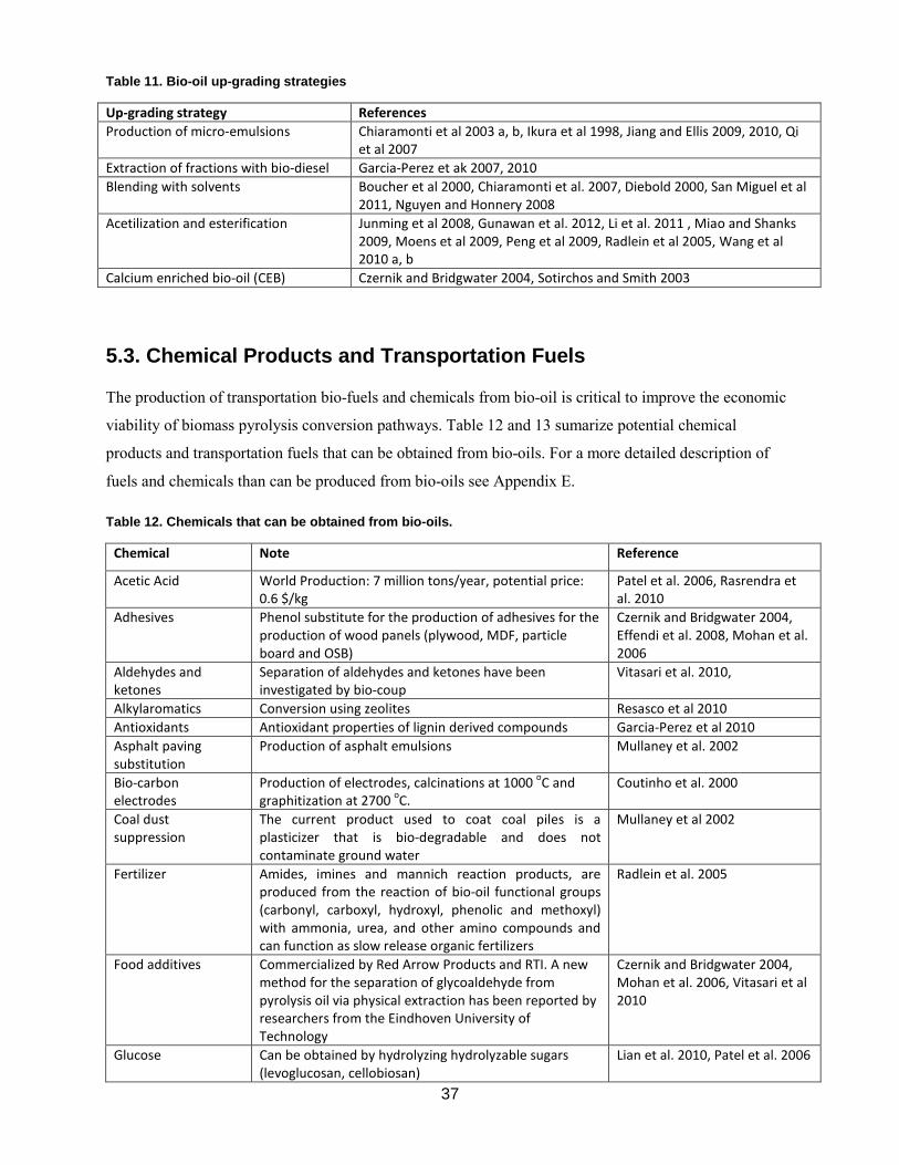
37
Table 11. Bio-oil up-grading strategies
Up-grading strategy References Production of micro-emulsions Chiaramonti et al 2003 a, b, Ikura et al 1998, Jiang and Ellis 2009, 2010, Qi
et al 2007 Extraction of fractions with bio-diesel Garcia-Perez et ak 2007, 2010 Blending with solvents Boucher et al 2000, Chiaramonti et al. 2007, Diebold 2000, San Miguel et al
2011, Nguyen and Honnery 2008 Acetilization and esterification Junming et al 2008, Gunawan et al. 2012, Li et al. 2011 , Miao and Shanks
2009, Moens et al 2009, Peng et al 2009, Radlein et al 2005, Wang et al 2010 a, b
Calcium enriched bio-oil (CEB) Czernik and Bridgwater 2004, Sotirchos and Smith 2003
5.3. Chemical Products and Transportation Fuels
The production of transportation bio-fuels and chemicals from bio-oil is critical to improve the economic
viability of biomass pyrolysis conversion pathways. Table 12 and 13 sumarize potential chemical
products and transportation fuels that can be obtained from bio-oils. For a more detailed description of
fuels and chemicals than can be produced from bio-oils see Appendix E.
Table 12. Chemicals that can be obtained from bio-oils.
Chemical Note Reference
Acetic Acid World Production: 7 million tons/year, potential price: 0.6 $/kg
Patel et al. 2006, Rasrendra et al. 2010
Adhesives Phenol substitute for the production of adhesives for the production of wood panels (plywood, MDF, particle board and OSB)
Czernik and Bridgwater 2004, Effendi et al. 2008, Mohan et al. 2006
Aldehydes and ketones
Separation of aldehydes and ketones have been investigated by bio-coup
Vitasari et al. 2010,
Alkylaromatics Conversion using zeolites Resasco et al 2010 Antioxidants Antioxidant properties of lignin derived compounds Garcia-Perez et al 2010 Asphalt paving substitution
Production of asphalt emulsions Mullaney et al. 2002
Bio-carbon electrodes
Production of electrodes, calcinations at 1000 oC and graphitization at 2700 oC.
Coutinho et al. 2000
Coal dust suppression
The current product used to coat coal piles is a plasticizer that is bio-degradable and does not contaminate ground water
Mullaney et al 2002
Fertilizer Amides, imines and mannich reaction products, are produced from the reaction of bio-oil functional groups (carbonyl, carboxyl, hydroxyl, phenolic and methoxyl) with ammonia, urea, and other amino compounds and can function as slow release organic fertilizers
Radlein et al. 2005
Food additives Commercialized by Red Arrow Products and RTI. A new method for the separation of glycoaldehyde from pyrolysis oil via physical extraction has been reported by researchers from the Eindhoven University of Technology
Czernik and Bridgwater 2004, Mohan et al. 2006, Vitasari et al 2010
Glucose Can be obtained by hydrolyzing hydrolyzable sugars (levoglucosan, cellobiosan)
Lian et al. 2010, Patel et al. 2006

38
Chemical Note Reference
5-hydroxymethyl furfural (HMF)
Attractive building block for further derivatization Patel et al. 2006
Levoglucosan By using demineralized cellulose, high yields of levoglucosan (up to 46 wt. %) and levoglucosenone (up to 24 wt. %) can be generated
Czernik and Bridgwater 2004, Radlein et al (1999)
Methanol Can be produced from the distillation of pyrolighneous water
Emrich 1985
Pesticides Significant activity against two bacteria and and the Colorado potato beetle were shown using bio-oil derived from dried coffee grounds
Bedmutha et al. 2011, Booker et al. 2010
Impermiabilizer Black residue of tar distillation commercialized to impermiabilize ships
Emrich 1985
Road de-icer Calcium salts of carboxylic acids Czernik and Bridgwater 2004 Surfactants More than 10 commercial grades are used for ore
flotation Emrich 1985
Wood preservatives Bio-oils can act as insecticides and fungicides due to some of the terpenoid and phenolic compounds present
Czernik and Bridgwater 2004, Mohan et al. 2008
Table 13. High value fuels derived from bio-oils.
Fuel References Hydrogen production Bleeker et al 2010, Czernik et al. 1999, Davidian et al. 2007, Galdamez et al. 2005, Medrano
et al. 2010, Rioche et al. 2005, Takanabe et al. 2004, Wang et al. 1997, 1999, Wang et al. 1997, 1998)
Synthesis gas van Rossum et al. 2007, Mohan et al. 2006 Ethanol Bennett et al 2009, Lian et al 2010, Miyafiji et al 2005, Olson and Freel 2007, Patel et al.
2006, Prosen et al. 1993, Shafizadeh and Stevenson 1982. Hydrotreatment to Produce hydrocarbons
Adjaye et al. 1996, Baker and Elliott 1993, Bui et al. 2009, Christensen et al 2011, De Miguel-Mercader 2010, Elliott and Baker 1989, Elliott et al. 2009, 2010, French et al. 2009, 2010 and 2011, Furimisky 2000, Hogendoorn and de Miguel Mercader 2010, Maggi and Delmon 1997, Mahfud 2007, Oasmaa et al 2010, Senol et al 2005, Tang et al 2009, Vanderbosch et al. 2010, Wildschut et al. 2009 and 2010, Wilson and Williams 2003, Wright et al. 2010
5.4. Bio-oil Refineries
Integrating pyrolysis technologies into bio-refinery concepts to fully utilize all bio-oil fractions is a
primary challenge facing the thermochemical conversion industry and scientific community. Although
bio-oil up-grading is currently limited to laboratory and pilot plant studies, rapid developments in this
area are occurring (Buttler et al 2011). To improve the economic viability of bio-oil refineries, the
combined production of drop-in fuels for large markets and high-value products for niche markets is
needed. The integration of these new dimensions into the existing infrastructure (e.g. the pulp and paper
industry or petroleum refineries) is another important consideration for enhancing the economic viability
of pyrolysis technologies.
The old wood distillation industry usually delivered crude products (pyroligneous acid and tars) to
specialized distilleries. The rectification and separation of methanol, acetone and acetic acid in the old

39
wood distillation industry was often performed separately to the carbonization itself (Emrich et al. 1985).
The new bio-oil refineries could also make use of similar concepts. In this section we discuss several bio-
refinery concepts. An excellent review on recent laboratory and commercial developments in fast
pyrolysis and up-grading has been recently published by Buttler et al (2011).
5.4.1 Bio-oil Refinery Schemes Based on Hydrotreatment One of the main challenges to utilize bio-oils as a feedstock to produce hydrocarbon like biofuels is their
high oxygen content (~46%). To produce green gasoline or diesel oxygen has to be removed from bio-oil
typically with hydrogen in a process known as hydrotreatment. Although, there are different ways to
produce the hydrogen needed for the hydrotreatment step (partial oxidation of residual oils, gasification of
coal, and water electrolysis), steam reforming of gases like methane, ethane and propane is by far the
most commonly used method. According to Jones et al (2009) 16% of the cost of the hydrotreated bio-oil
will be associated to the natural gas used to produce the hydrogen needed for the hydrotreatment step.
During steam reforming the C1-C4 hydrocarbons are heated at temperatures over 800 oC and mixed with
water vapor (steam) in a presence of a Ni based catalyst to produce hydrogen, CO and CO2 as shown in
the following chemicals reactions:
CH4 + H20 3H2 + CO
C3H8 + 3H20 7H2 + 3CO
C4H10 + 4H20 9H2 + 4CO
CO + H20 H2 + CO2
The CO not converted in the steam reformed is then converted at lower temperatures in a Water Shift
reactor. The CO2 in the gas stream is then removed by adsorption or absorption. The purified hydrogen
produced is then compressed and used in the hydrotreatment step.
Marinangeli et al. (2005) studied several options for using whole crude pyrolysis oil and its two fractions
(pyrolytic lignin (decanted oil) and the water soluble phase) to produce transportation fuels. Decanted oil
can be converted into gasoline with lower H2 consumption using mild hydrotreating followed by
hydrocracking (bio-oil molecules are catalytically broken into smaller molecules in the range of gasoline
and kerosene) (Marinangeli et al. 2005). Three bio-oil refinery schemes evaluated by Marinangeli et al.
(2005) are shown in Figure 21.

40
Figure 21. Processing routes for pyrolysis oil (Adapted from: Marinangeli 2005).
In the first scheme, the water-soluble phase of pyrolysis oils is considered suitable for generating
hydrogen. Steam reforming of the water-soluble portion of pyrolysis oil can provide most or all of the
hydrogen used in a bio-oil refinery (Marinangeli et al. 2005). Removing oxygen from decanted oil (rich in
lignin derived compounds) naturally generates materials in the gasoline boiling range because of the
molecular structure of this phase. The decanted phase has less oxygen and as such requires less hydrogen
than pyrolysis oil (Marinangeli et al. 2005).
The second scheme assumes that the aqueous phase is used to produce heat and steam. Thus, the
hydrogen consumed for the hydrotreatment of the decanted oil is generated through the use of
conventional means.
The third scheme considers that no hydrogen will be produced from the bio-oil and that the whole bio-oil
will be hydro-thermally treated. The fact that large quantities of hydrogen are required to generate water
during hydrotreatment, due to the high levels of oxygen (46%) in pyrolysis oil, is the main drawback with
this concept (Marinangeli et al. 2005). Although the hydrotreatment of decanted oil can be conducted in a
single step, the hydrotreatment of the whole bio-oil has to be conducted in two steps. The main purpose of
the first hydrotreatment step is to stabilize aldehyde groups and/or reduce the oxygen content and the total
acid number (TAN). Transportation fuel is produced in the second hydrocracking step (Holmgren et al.

41
2008). A scheme in which water is separated after the first hydrotreatment step is described in Figure 22.
The main disadvantage here is that some pyrolytic sugars are lost in the water phase due to solubility.
Figure 22. Hydrotreating/hydrocracking of pyrolytic lignin process flow (Marinangeli et al. 2005).
Hydrogen consumption and product yield from bio-oil hydroprocessing is shown in Table 14 (Holmgren
et al. 2008). About 41 wt. % of the bio-oil is converted into products in the naphtha and diesel range
(Holmgren et al. 2008).
Table 14. Estimated consumption of hydrogen and yield of diesel and naphtha obtained from pyrolysis oil
hydrotreatment (wt. %) (Holmgren et al. 2008).
Feed Wt. % H2 3-4.5 Products Naphtha range 21 Diesel range 21 Water, CO2, more volatile compounds (lights) 60
The composition of multiple samples of the gasoline range product from bio-oil hydroprocessing is
compared to gasoline composition in Table 15. Based on pyrolysis oil, carbon recovery is about 50%
(Holmgren et al. 2008). Clearly, the content of parafins and iso-parafins is much lower in hydrotreated
bio-oil than in commercial gasoline. Naphthene content is considerably higher. The source of parafins and
iso-parafins is not well known, but naphthene is produced from lignin derived intermediates.
Table 15. Gasoline cut of a hydroprocessed bio-oil (wt. %) composition (Holmgreen et al. 2008).
Hydroprocessed Bio-oil (from mixed wood) Gasoline Min. Max. Parafins 5.2 9.5 44.2 Iso-paraffins 16.7 24.9 35 Olefins 0.6 0.9 4.1 Naphthene 39.6 55.0 7 Aromatic 9.9 34.6 38 Oxygenate 0.8

42
Jones et al. (2009) describe several refining pathways and presents mass and energy balances of several
concepts for a 2,000 dry metric tons/day plant to process hybrid poplar chips. An important parameter
influencing the economic viability of a bio-oil refinery is the possibility of co-locating the plant with an
existing refinery (Jones et al. 2009). A detailed overview of the two-step stabilization section and
preheater are shown in Figure 23.6
Figure 23. Pyrolysis stabilization flow diagram (Adapted from: Jones et al. 2009).
The concept of distributed pyrolysis units followed by hydrotreatment in a centralized refinery is being
pursued by Evergent (www.envergenttech.com). This is a joint venture between Ensyn’s Rapid Thermal
Preprocessing (RTP) and UOP Hydroprocessing Technologies (Buttler et al. 2011). The first 1 ton/day
demonstration unit able to produce 4 barrels per day of gasoline, diesel and jet fuel is expected to be
operational in 2014 at the Tesoro Corporation refinery in Kapolei Hawaii (Elliot et al. 2010, Gross 2010).
There are plans to build other 9 new systems in Malasia (Buttler et al. 2011, Tan 2010). Dynamotive
(www.dynamotive.com) and IFP are also pursuing an association to produce transportation fuels via
hydrotreatment (Buttler et al. 2011, Radlein et al 2010).
6 For further details see Jones et al. 2009.

43
5.4.2 Alternative Bio-oil Refinery Concepts The concepts described in the previous section target the production of fuel with limited emphasis on
high-value bio-products. High-value bio-oil products are critical to enhance the economic viability of a
rural bio-oil refinery. Schemes that integrate the production of high-value chemicals with bio-fuels
production are discussed here.
The bio-refinery concept employed by the old wood distillation industry produced biochar, tars, acetone
and wood naphtha (Figure 24). Slow pyrolysis technologies were the basis for this industry. The
separation of decanted tar and dissolved tar is shown in Figure 24. While decanted tars are lignin
products, dissolved tars are presumably products derived from the carbohydrate fraction (Hawley and
Calderwood 1925). As explained in the previous section, advanced hydrotreatment methods now allow
production of transportation fuels from these tars.
Figure 24. Old wood distillation industry’s bio-refinery concept (Klar and Rule 1925).
After the separation of the crude wood spirit (Figure 24) the pyroligneous acid is distilled in copper
vessels and a limewash is used to collect the acetic acid and water vapors. Using drums at a temperature
no higher than 180 oC, the precipitated lime acetate is dry-evaporated. This crude acetate contains 80%
calcium acetate by weight and is also known as grey acetate (Emrich 1985). An acetic acid at 85% can be
obtained by decomposing grey acetate with sulfuric acid. An alternative method can be used to obtain

44
acetone which includes heating grey acetate to 400-500 oC. Rectification (Figure 24) can be used to purify
the crude acetone (Emrich et al. 1985). Passing the pyroligneous acid over catalysts at 500 oC is another
alternative to obtain acetone.
Direct recovery of acetic acid by distillation is another process used to refine the aqueous phase (Emrich
1985). The first step is distillation of the pyroligneous acid from a weak acid solution. Toluene (C7H8) is
used by several companies during the distillation process to draw off the moisture. The two stage process
is slightly more sophisticated. Upon distillation in the first step, the solution is diluted with xylene which
combines with water to form a binary mixture with a very low boiling point. Once the concentration of
acetic acid is obtained from the first stage, it is then distilled again with benzene to form a fresh mixture
(Emrich 1985).
The des Products Chemiques de Clamancy and Lambiotte Brother plant developed a slightly different
method (Emrich 1985). This method eliminates moisture with the distillation of an azeotrope formed with
butyl acetate, or using a tar reactor with a counter-current of circulating butyl acetate through which a
fraction of the wood spirit is passed (Emrich 1985).
The acetic acid ether method is used by a plant belonging to the Deutsche Gold und Silber
Scheidenanstalt, to extract acetic acid. A ten meter tower with a counter current of acetic ether introduced
from the bottom is then used as the extraction tower. The pyroligneous acid obtained from the wood spirit
is introduced into the top of this tower. In order to ensure good contact, the tower is fitted with rashings
rings (Emrich 1985). The run-off water at the bottom of the tower contains some dissolved ether which
can be collected through rectification. From the top, a mixture of ether and acetic acid with little tar is
released. Using rectification, the collected ether can be recycled back into the extraction tower. Vacuum
distillation is then used to separate the crude acetic acid from any remaining tar. An acetic acid of 95% is
the result (Emrich 1985).
Tar processing: Tar is obtained at different locations in the plant throughout the entire process and kept
separate in tanks (Emrich et al. 1985). A large quantity of tar can be secured from the settling of pyrolysis
oil before the process even begins. Commercial uses of tar obtained from pyrolysis are shown in Figure
25.

45
Figure 25. Commercial products from recovered pyrolytic tar (Emrich 1985).
By distilling the tar, the content of waste, wood spirits, and light oils can be separated. Most of the
moisture, acetic acid, wood spirit, and light oils are given off when the tar is heated to 140 oC. Direct
introduction of steam further heats the tar until no more acetic acid is carried off. A tar free of moisture
and acid that still contains heavy oils is the retort residue. An open fire retort similar to those used in
distilling coal tar can be used to separate the creosote. Since tar tends to froth, preliminary heating should
be done with care. After completion of the first distilling step at around 110 oC, the temperature should be
raised to 250 – 260 oC before resuming distillation. Different vessels are used to collect the oils which are
respectively lighter and heavier than water. Once the operation is completed at a temperature of 260 oC,
the residue of tar distillation (pyrolytic pitch) remains (Emrich 1985). This pitch has a dark brown or
black color. Four different grades of tar, marketed by their softening points, are typically supplied by
charcoal plants (Emrich 1985).
Use of organic solvents is another method to separate fast pyrolysis bio-oil. In Figure 26, lignin derived
tars are extracted with ethyl acetate. Separating the phenolic fraction from the lignin and sugars that are
derived from the cellulose with solvent extraction is the first step. This solvent extraction step results in
pyrolytic sugars in aqueous phase (levoglucosan and cellobiosan). These pyrolytic sugars are then
hydrolyzed to mono-sugars, detoxified (removing most of the acids and phenols), neutralized to an
appropriate pH, and finally, fermented to produce ethanol. It is important to reduce the tendency of the
phenolic fraction to form coke during combustion or hydrotreatment by the separation and full utilization
of the sugars (Garcia-Perez et al. 2009). The advantage of this method is that the energy needed to
concentrate products from the water soluble fraction is minimized since the aqueous phase is not very
diluted with water. A disadvantage of this method is the use of organic solvents, which must be recycled.
Brown (2010) proposed a bio-oil refinery concept with three condensation steps to produce heavy lignin
oligomers and sugars, mono-phenols and a light fraction rich in C1-C4 oxygenated molecules. By adding
water into the fraction rich in sugars, sugars and lignin oligomers can be separated. Aliphatic compounds
are then produced by hydrotreating the sugars (Figure 27).
TAR
TAR OIL LIGHT
Heating Oil Creosotes
Guaiocol
Heating Oil
TAR RESIDUES FROM STILL
Froth flotation oil
Wood preservative
Insulation, Electrodes
TAR OIL HEAVY

46
Figure 26. Alternative concept for the production of ethanol and tar rich in phenols in a bio-refinery (Garcia-
Perez et al. 2009).
Figure 27. Strategy for up-grading bio-oil (Brown 2010).
Bio-oil gasification and further conversion of syngas to produce valuable products is another concept of
interest (Figure 28) (Henrich et al. 2009). Extensive studies have explored the production of syngas from

47
pyrolysis oil (van Rossum et al. 2007, Wright et al. 2008). An estimate of the material and energy
balances for the total process is presented by Henrich et al. (2009). The Bioliq concept proposed by KIT
(Germany) consisting in the production of a bioslurry followed by its gasification is being tested in 12
tons per day a demonstration plant commissioned in 2008 (Henrich 2007, Dahmen 2010).
The esterification and acetylation of bio-oils has been used as the main concept for the bio-oil refinery
concept proposed by Radlein (2005) (Figure 29). This concept has been studied expetnsively by other
researchers (Gunawan et al. 2012, Li et al 2011, Moens et al 2009, Peng et al 2009).
An integrative overview of the options studied by Biomass Technology Group (BTG) to process pyrolysis
oils is shown in Figure 30. This figure integrates several technologies described in previous sections.
Figure 28. Simplified scheme which uses bio-oil/biochar slurries to produce Fischer-Tropsch (FT) syngas (Henrich et al. 2009).

48
Figure 29. Bio-oil refinery concept based on the acetilization of esterified bio-oil (Radlein 2005).
Figure 30. Bio-refinery vision of BTG (source: http://www.btgworld.com/index.php?id=23&rid=8&r=rd).
5.5. Biochar Products
Today there are two main markets for biochar utilization: industrial applications (activated carbon and
metallurgical applications) and household markets. The development of environmental, agricultural and
silvacultural applications of biochars also may open new markets. Each market is associated with

49
different tactics, individual specifications, packing styles and marketing habits. New markets for biochar
products (e.g. carbon sequestration), will inevitably require specialized producers (Emrich 1985, Toole
1961). This section provides a comprehensive overview of products that can be produced from biochar7.
5.5.1 Household Fuel The use of biochar for cooking is common in many developing countries. Cooking with biochar in
industrialized countries has developed specifically for patios, gardens, beaches, camp sites and public
spaces.8 Lump biochar is a preferred cooking fuel in developing nations and users are aware of significant
differences in cooking time and calorific values of different chars (Emrich 1985, Kambewa et al. 2007).
Biochar briquettes were introduced into the United States in 1955. Export specifications of biochar for
cooking are shown in Table 16 (Emrich 1985).
Table 16. Specifications for biochar export (Emrich 1985).
Properties Lump biochar Briquettes Without energy extender With energy extender
Ashes (wt. %) 3 – 4 Max. 8 Max. 25 Moisture (wt. %) Less than 5 5 5 Carbon (wt. %) 80 – 82 70-75 60-65 Volatiles (wt. %) 10 – 15 10-15 10-15 Binder (wt. %) - Max 8 Max. 8 Calorific Value (kcal/kg) 6,800 – 7,200 6,000 5,200
5.5.2 Activated Carbon - Activating Biochar Activated carbon refers to many types of carbon that have been treated to increase its adsorptive
properties. Because the adsorptive properties of existing activated carbon are based on the surface area of
their carbonaceous matrices, activated carbon tends to be produced from feedstocks with low ash content
(example wood, coconut shells and hard coal). The high ash content of some biomasses makes it difficult
to achieve very high surface area, but may confer some interesting characteristics to biochars for
environmental applications. Activated carbon is used in liquid and gas phase adsorption processes and is
available in either a powder or granular (extruded) form. Adsorption onto activated carbon is often
considered the most economical for the removal of organic compounds and metals from diluted aqueous
solutions. US-EPA has stated that activated carbon adsorption is one the best available environmental
control technologies (Marsh and Rodriguez-Reinoso 2006, Derbyshire et al 2001). Although biochar can
be obtained from any biomass, producing activated carbon that is capable of performing with the
efficiency required for industrial applications does not happen easily (Marsh and Rodriguez-Reinoso
2006). Commercial activated carbon on the market today is the result of intensive research and 7 Further information and detail is provided by Marsh and Rodriguez-Reinoso 2006 and Emrich 1985.
8 Using charcoal as fuel and its efficiency is described by the Food and Argiculture Organization (FAO 1987).

50
development to optimize various applications. Activated biochar may find new markets for numerous
applications in the ecosystem if materials wit acceptable sorption properties could be produced at a
fraction of current activated carbon production cost using waste lignocellulosic materials as feedstocks.
The usability of wood biochar for activated carbon depends on the ash content and its availability in
uniform and unvarying quality. Biochar made from coconut shells, hardwood species, sawdust and wood
waste (with the exception of bark), can produce exceptionally good activated carbon (Emrich 1985). In
order to adsorb molecules of different sizes, activated carbon must have a large volume of micropores
with the appropriate pore size distribution. An adequate proportion of mesopores is also necessary to
facilitate access to the micropores (Marsh and Rodriguez-Reinoso 2006).
In addition to a thorough physico-chemical characterization, the activated carbon producer should test the
biochar to determine the adsorption capacity of the finished product before commercializing the material.
The molasses index, the methylene blue value and isotherms of benzene are tests developed by the
industry to evaluate the quality of activated carbons. Similar tests must be developed for biochar designed
for environmental applications to guarantee the products capacity to adsorb common pollutants.
Nowadays there are ongoing research processes to identify the applications of biochars according to their
specific characteristics. However, there is not yet a rapid screening technique to relate the biochar
characteristics with a particular use (http://www.anzbiochar.org/publications.html#publications).
Industrial applications that may use activated carbon include liquid and gas phase applications. Liquid
phase applications include municipal wastewater and industrial wastewater treatment plants, swimming
pools, tropical centers, fish tanks, and drinking water. Also included in this list is the purification of oils,
fats, winery tanks, beverages, and tank cleaning in insecticide and pesticide spraying operations.
Gas/vapor phase applications include purification of exhaust emissions, recirculated air purification,
solvent recovery in printing machinery and processes where high volatile matter is continuously being
released. It also can be used to prevent offensive odors. Table 17 shows some applications of activated
carbon in different industrial processes.
Adsorption capacity and surface area of activated carbon are interrelated. However, surface area is only
one factor to measure the adsorptive capacity for a specific purpose. Activated carbon with large total
surface areas and with micropores may be ineffective in adsorbing larger color forming compounds from
solutions, while they may be effective in removing small odor-causing impurities from gases. This
explains a large number of shapes, grades and types of activated carbon on the market (Emrich 1985).
Chemical and physical means are used to conduct biochar activation.

51
Table 17. Uses of activated carbon (Source: from information from Marsh and Rodriguez-Reinoso 2006)
Applications Industrial examples Main Compunds Liquid-phase adsorption Adsorption of inorganic solutes from aqueous solution
Heavy metals removal from wastewater treatment systems.
Mercury, chromium, molybdenum, cobalt, nickel, copper, cadmium, lead, uranium, gold, arsenic, barium, iron and vanadium.
Adsorption of organic solutes from aqueous solutions
Drinking water, wastewater treatment, food and beverage, pharmaceutical and chemical industries.
Phenols, natural organic matter (NOM), aniline, nitrobenzene, benzoic acid, and pesticides.
Gas-phase applications Gas purification Chemical industry, reduction of
pollutants, protection against poison gases, odor control, etc.
H2S, SOx, NOx, volatile organic compounds (VOC).
Separation of gas mixtures
Air separation, treatment of landfill gas, purification of natural gas, tertiary oil recovery
Nitrogen from oxygen, CO2 from landfill gas, CO2 from natural gas, CO2/CH4 from effluent gas on tertiary oil recovery.
Methane storage Storage of natural gas adsorbed on activated carbon.
CH4
Solvent Recovery Paint, petrochemical, printing, rubber, synthetic fiber, adhesives, metal fabrication, solvent manufacturing, and coating industries.
Acetone, benzene, ethanol, ethyl ether, pentane, methylene chloride, tetrahydrofuran, toluene, xylene, chlorinated hydrocarbons and aromatics.
Liquid-phase applications Water treatment Removal of pollutants organic
compounds: i) natural organic matter (NOM), ii) synthetic organic compunds, iii) by-products of chemical water treatment.
i)-Residues of the metabolism of living things, ii) oil, benzene and toluene, phenols and chlorophenols, trichloromethane and carbon tetrachloride, detergents, pesticides, dyes, surfactants, etc. iii) trihalomethanes with chlorine (CHCl3, CHBrCl2, CHBr2Cl and, CHBr3).
Chemical and pharmaceutical
i)_Control product quality, iii) removal of toxic chemicals, iii) extraction of pharmaceuticals in processes involving fermentation iv) filters for dialysis of poisons and drugs, felts for wounds, etc.
Recovery of antiobiotics, vitamins, and steroids.
Adsorption of dyes Wastewater treatment of the dyes industry.
Acid, basic, reactive, direct, disperse, sulfur and metallic dyes.
Porous carbons in catalytic processes Carbon-supported catalysts
Platinum, palladium and iron supported on activated carbon.
Catalytic hydrogenation of α, β-unsaturated aldehydes to give unsaturade alcohols, hydrogenations of crotonaldehyde, CO hydrogenation etc.
Catalysis by carbon surfaces
i)_Production of phosgene (carbonyl chloride), ii) reactions involving hydrogen, iii) reactions involving oxygen, and iv) reactions involving halogen.
i)_Formation of phosgene by combination of carbon monoxide and chlorine ii) RX + H2 RX (X = CL, Br), iii) NO + (1/2)O2 NO2 iv) SO2 + Cl2 SO2Cl2

52
Physical activation (thermal steam activation): Thermal activation is a process of selective gasification
(removal) of individual carbon atoms. The weakest carbon atoms can be removed from within porous
carbon by using gasification or water vapor (at 700-1,000 oC). Carbon with varying porosities can be
produced in presence of carbon dioxide and steam (Marsh and Rodriguez-Reinoso 2006). Powdered
carbon is often extruded in presses before activation, with the aid of coking binders. The extruded product
is carbonized at only moderate temperatures. It is activated by water vapor in a rotary furnace or in a
fluidized bed (Emrich 1985). The art of the processor lies in conducting the activation process in such a
way that combustion of the carbon does not take place from outside of the grains (Emrich 1985). Figure
31 shows an activation plan for the production of activated carbon pellets (Emrich 1985).
Figure 31. Activated carbon plan for manufacturing pellets or granular activated carbon (Emrich 1985).
Chemical activation: Three common methods of chemical activation involve zinc chloride, phosphoric
acid, and potassium hydroxide. The mechanisms for these activations are all different. Zinc chloride
promotes the extraction of water molecules from the lignocellulosic structures of parent materials.
Phosphoric acid combines chemically within the lignocellulosic structures. Potassium hydroxide effect,
follows a more complex mechanism. It involves disintegration (explosively) of a structure following
intercalation as well as some gasification by the oxygen of the hydroxide group (Marsh and Rodriguez-
Reinoso 2006).
Activation strategies for environmental applications: The market for activated carbon for industrial and
household use is not large enough for the amount of biochar that could be produced from the waste
materials generated in Washington State. However, if we could get substantialy the same result with

53
“activated biochar” at a fraction of the cost of activated carbon, the market for ecological and
environmental applications may grow dramatically. In the case of environmental applications
regeneration is not likely to occur. In order to reduce costs biochars should be produced from materials
with higher ash content with lower value on energy markets. The minerals contained in the biochar “ash”
(Fe, Mn, Alkalines) can have a profound impact on the ability of biochar to “cleanup” some pollutants in
waste gas and liquids perhaps at much lower costs that activated carbon.
Rearchers at Washington State University are currently studying the development of biochars to remove
nutrients (P and N) from Anaerobic digesters. Dairies in Washington State produce over 1.5 million tons
of manure annually accounting for 18,900 tons of phosphorous that is concentrated in lagoons prior to
land application. Annual land applications have led to concerns of environmental degradation caused by
NO3 leaching and P runoff. These applications may deliver > 600 kg N ha-1 y-1 and 160 kg P ha-1 y-1
exceeding the needs of crops, resulting in leaching to groundwater or runoff losses to waterways. The
land disposal of manure from dairy operations has led to excess phosphorous accumulation causing an
extreme risk to the environmental quality of the Pacific Northwest (PNW) region. One method for
nutrient management and reclamation of nutrients on dairy farms is the use of anaerobic digesters for the
production of methane gas and electricity production. After digestion, the effluent flowing from the
digester is a combination of nutrients and undigested fiber while the liquid effluent remains high in P and
N. Ideally the excess P and N within the effluent stream could be recovered as a fertilizer and exported off
farm. The design of biochars with simulateneous buffering and nutrient adsprotion capacity should be
further investigated.
Carboxylic acid groups on the surface of biochar are essential for improving the biochars nutrient holding
capacity, as well as polarizing the surface which may also increase water retention of the material. A high
proportion of carboxyl acids as well as other acidic oxygen groups may also provide biochar many of the
desirable properties of humic acid which is an important degradation product of soil organic matter. The
relatively high concentration of acidic groups can allow the formation of chelates with metal ions and
help to bind positively charged ions to the surface of the carbon. When the surface density of carboxylic
acid groups is very high, chelates with metal ions can almost completely immobilize potentially toxic
metal compounds. The results obtained by Valdes (2002) indicate that total acidic groups on activated
carbons can reach at least 2 meqg-1 with half the acidic groups being carboxyl groups. Smith (2011)
showed that biochar ozonation could be an excellent approach to generate acidic functional groups on
biochar surface and enhance its capacity to remove nitrogen from waste streams. The author (Smith
2011) proved that the pH at zero charge of ozonated biochars is considerably reduced when the biochar is
oxidized. The acidic nature of oxidized biochars means that they may be well suited for retention of basic
ions such as ammonia or other cation compounds (Kastner, 2009). Chiang et al. (2002) has shown a

54
strong correlation between the quantity of ammonia adsorbed by the oxidized carbon and the
concentration of acid groups on the surface.
The adsorption of phosphate ions will depend mostly on the concentration and accessability of cations
found in the ash. Effects of metal ion concentrations in fly ash have been the subject of significant
research (Lu, et al., 2009; Agyei et al., 2000; 2002; Namasivayam and Sangeetha 2004; Oguz, 2005; Xue
et al., 2009). The use of fly ash has been considered for its potential to remove phosphate compounds
from waste water. The biochar ash composition plays an important role in the adsorption or precipitation
of suspended phosphates (Xue et al 2009), in basic solutions (pH>7) biochar ash with high content of
calcite is effective in phosphate removal (Lu et al 2009), in acidic conditions, biochar ash rich in
aluminum and iron induces precipitation of phosphates (Oguz 2005). The application of this information
to biochars for the removal of relatively low concentration phosphates is of interest, because of the desire
to develop an adsorbent capable of removing both nitrogen and phosphorous compounds from waste
streams. The addition of appropriate metal ions to the structure of the biomass should aid in creating
additional basic sites on the char surface which will become positively charged in solution and attract
anions to the surface.
Streubel et al. (2011) studied the role untreated and freshly produced biochar can have on nutrient
adsorption by allowing AD effluent to be filtered through the char-media for 15 days. Results showed that
the char sequestered an average of 381 mg/L P from the AD effluent as a coating on the biochar. There
was an increase of total (1.9 g kg-1), Olsen (763 mg kg-1), and water extractable P (914 mg kg-1) bound
to the biochar accounting for a recovery of 32% of the P in the AD effluent. While the study was
completed with untreated biochar, it is possible to design biochars with modified surface acidity/area, and
cation/anion exchange capacities and with a different ash composition to further enhance nutrient
removals from AD effluents.
5.5.3 Industrial Applications Due to increased environmental regulation and diversification of the chemical industry, applications of
biochar for the industrial market have multiplied. Industrial applications of biochar include gas generation
(for cars, electric power), fuel for the cement industry, iron and steel industry, metallurgy (blast iron
furnaces, ferro-silica, metal hardening, non-ferrous metal industry) and the chemical industry (e.g.
manufacturing carbon disulphide, sodium cyanide, carbides) (Emrich 1985).
Wood charcoal (biochar) was universally used as a reductant when iron was first made by man. During
the eighteenth century, metallurgical coke was introduced as an alternative. Today, the largest biochar
based pig-iron industry in the world is located in Brazil (Pelaez-Samaniego et al. 2008). Biochar provides
strong reducing properties. Metal extraction is facilitated when carbon is heated with ores containing

55
metal, oxides, and sulfides and the carbon readily combines with oxygen and sulphur. Hardwood species
(eucalyptus) makes up most of the biochar used in blast furnaces. Despite the fact that biochar is generally
acknowledged to be as good, if not better, than coke, it is challenging to obtain adequate supplies of
biochar to feed large iron and steel industry, which are needed to achieve competitive steel prices (Emrich
1985).
Properties that need to be accounted for in order to provide continued use of biochar in metallurgical
applications include: 1) relatively few and un-reactive inorganic impurities, 2) specific pore structure with
large surface area, 3) almost smokeless, 4) low sulfur content, 5) good reduction ability and 6) a high
carbon to ash ratio (Emrich 1985).
5.5.4 Carbon Sequestration and Soil Fertility Public interest in the potential of biochar to sequester carbon and enhance soil fertility is growing
(Lehmann and Stephen 2009). Using biochar to enhance soil fertility is a market that could utilize a vast
majority of the organic waste generated in the state (Granaststein et al 2009, Garcia-Perez and Smith
2011). The main obstacle for this application is that the price for carbon sequestration with biochar is not
high enough to justify its production (Garcia-Perez et al. 2010). To increase the economic viability of
using biochars as soil amendments, functionalized biochars that can provide more than one environmental
function (e.g. increased water holding capacity, improved fertilizer efficiency, sorption of persticides) and
consequently receive higher prices. Benefits from engineered biochars in agriculture include: 1) Improved
water holding capacity at the root zone; 2) Improved fertilizer holding capacity at the root zone and 3)
improved soil health. Multiple benefits can improve the value of the biochar product. In addition,
markets for activated carbon can also provide improved off-take value.
The West Coast has a range of distinctly different approaches to carbon sequestration: 1) British
Columbia has a carbon tax (http://www.fin.gov.bc.ca/tbs/tp/climate/carbon_tax.htm); 2) California has a
cap & trade system (http://www.arb.ca.gov/cc/capandtrade/capandtrade.htm) ; 3) Oregon has The Climate
Trust (http://www.climatetrust.org/) ; and 4) Washington has an emission inventory and reporting law
(RCW 70.94.151) and greenhouse gas reduction limits (RCW 70.235.020). In the last few years,
voluntary markets for renewable energy in US have been growing due to its greenhouse gas (GHG)
benefits (Bird et al., 2008). Emerging carbon regulation efforts had focused on the Regional Greenhouse
Gas Initiative in the Northeast, the Western Climate Initiative, and the Midwestern Greenhouse Gas
Reduction Accordto add to the current voluntary markets for renewable energy (Bird et al., 2008, Funk
2009,). A more recent state and province effort is called North America 2050: A Partnership for Progress
(http://na2050.org/). Working groups have been organised, however, terrestrial carbon sequestration
(turning farms from a source to a sink) is not a focus of this effort.

56
The economics of carbon sequestration through biochar (if biochar is approved for carbon storage
payments) could improve dramatically if it is inserted into a mandatory carbon cap with associated
markets or carbon cap and tax. Today, the value (based on its calorific content) of crude biochar without
additional treatment is approximately $66 per ton. If biochars are engineered to improve soil fertility, over
those obtained with untreated biochar, higher prices may be obtained. The economic value of biochar
could also be increased by its ability to adsorb nitrogen and phosphorous from waste water streams and
by increasing its cation/anion exchange capacity. Development of strategies to improve the capabiltities
of biochars to adsorb nitrogren and phosphorous from waste streams is an area of of intense study (Smith
2011). The potential use of biochars, used to remove nutrients from waste streams, as a soil amendment
and improving fertilizer efficieny is receiving growing attention (Lehmann and Joseph, 2009).
Studies of the Terra Preta soils in the Amazon basin provide much of the knowledge regarding the
potential benefits of biochar as a soil amendment (Lehman et al. 2009). As the evidence suggests, these
soils provide long lasting carbon storage and improve crop production due to the biochar-like materials
that have substantially altered the physical and chemical properties of these soils. Krug and Hollinger
(2003) stated that deep and extremely fertile soils in some areas of the Illinois Plain were developed under
anthropogenic conditions where char from natural and man made fires improved the soil organic carbon.
Downie et al., (2011) reported some places with Terra Preta in Australia with a significant better nutrients
content and cation exchange capacity compared with adjacents soils. They claimed that the existence of
these kinds of soils in temperate climates would help in both storing C and using biochar. On the other
hand, scientists in Japan have been researching biochar for years in temperate climate soils. They stated
that the effects of biochar in crops is related mainly to soil infertility and the presence of nitrogen-fixing
bacteria and symbiotic organisms that thrive in char amended soils (Ogawa and Okimori 2010). Ogawa
and Okimori (2010) observe that biochar effects are more evident in infertile tropical soils.
The least fertile soils can benefit the most from the addition of biochar. According to Ammonette (2010),
sustainable biochar technologies can offset up to 130 Gt CO2-C eq emissions worldwide during the first
century of adoption. With regard to biomass type, global soil fertility, and carbon intensity of fuel offset,
biochar offers a 22% advantage over the combustion of biomass. The three most important variables that
affect the impact of biochar uses are the recalcitrance of biochar, the carbon intensity of the fuel being
offset, and the biochar yield during pyrolysis (Amonette 2010, Woolf et al. 2010). Maximum avoided
emissions by the production of biochar and heat, as estimated by Woolf et al. (2010) and Amonette
(2010), could range from 1.0 to 1.8 GT CO2 Ceq yr-1. For 100 years, the cumulative avoided emissions
range from 66 to 130 GT CO2 – Ceq. The impact that slow pyrolysis technologies with heat recovery
could have on carbon cycling (production of heat and biochar) are illustrated in Figure 32.

57
Figure 32. Sustainable biochar production concept with the use of biochar to enhance soil fertility and sequester carbon (Amonette et al. 2010, Woolf et al. 2010).
Producing value-added biochars that can substantially enhance soil fertility as well as carbon storage is
critical since payment for carbon storage alone is unlikely to fully recover production costs.
5.5.5 Biochar Gasification Small gasifiers able to utilize biochar and wood as fuel to operate vehicles, boats, trains, and small
electric generators9 were developed during World War II. By the end of the war about 90% of the
vehicles in Sweden were powered by gasifiers and there were more than 700,000 wood gas generators
(FAO 1986). Updraft and downdraft gasifiers are the two main concepts used to operate these engines.
Hot gases that are usually laden with dust and contain up to 1 wt. % of tar and particulates are produced
by a downdraft gasifier. If the dust is not properly removed, costly problems with maintenance, repairs,
and reliability can occur. Improper removal of these syngas contaminants is the main cause of gasifier
engine system failure. The gas is very dirty during initial start up and must be burned in the gasifier until
the system is fully functional.
9 Designs of wood gas generators are found elsewhere (http://www.windward.org/notes/notes63/wal63_b.htm,
http://journeytoforever.org/biofuel_ woodgas.html, http://www.scribd.com/doc/31422608/Wood-Gas-as-Engine-
Fuel-1).

58
These gasifiers can also be coupled with Diesel Engines to produce Electricity. Replacement of up to 70%
of petroleum derived fuel with producer gas for operating stationary engines appears to be a worthwhile
investment, especially for isolated areas (SERI 1988). However, given the convenience of liquid fuels,
many users prefer to pay more despite the very clear advantages of replacing imported petroleum with
producer gas.
59
6. Regulatory Issues of Current Pyrolysis Technologies
6.1. Health and Safety of Handling Bio-oils
A better understanding of health and safety issues associated with bio-oil exposure is necessary to
develop safe working practices (Ringer et al. 2006). Although Diebold (1999) published a review of bio-
oil toxicity, the health risks posed by fast pyrolysis liquids have not been clearly elucidated. Nonetheless,
a limited degree of mutagenecity and teratogenicity is associated with fast pyrolysis liquids depending on
the source, chemical composition, and dosage (Diebold 1999, Oasmaa and Peacocke 2001).
Material and Safety Data Sheets (MSDS) for Bio-oils For the safe use, handling, storage and transportation of fast pyrolysis liquids, material and safety data
sheets are essential.10 But due to high variability in properties and limited development in commercial
systems, there is no universally accepted MSDS for bio-oils. Private producers have developed MSDS for
pyrolysis liquids (e.g. Ensyn, Dynamotive, BTG and Fortum). An MSDS which suitable for inclusion
with samples for shipment was prepared at Aston University (UK) (Oasmaa and Peacocke 2001).
Czernick prepared an MSDS with the IEA Bio-energy Pyrolysis Activity Group (Bridgwater et al. 1999).
Adequate safety equipment and facilities (e.g. protective clothing, chemical resistant gloves, safety
glasses or goggles and a well ventilated environment) are required when working with pyrolysis liquids.
It is likely that fast pyrolysis liquids will be classified as a “dangerous” or a “hazardous” substance for
transportation, and appropriate national and international regulations must be met. Since pyrolysis liquids
are not approved on the UN carriage list (UN 1999), its own classification UN 1993 Flammable Liquid,
N.O.S., (Fast Pyrolysis Liquid), 3, 1o(a), 2o(a), 1 must be provided (Table 18). Figure 33 shows packing
labels that should be used for domestic and international shipments.
10 Several bio-oil MSDS sheets can be found at: (1) http://www.pyne.co.uk/Resources/user/docs/CIRAD_MSDS-
Final.pdf and (2) http://www.unh.edu/p2/biooil/bounhif.pdf.

60
Table 18. Package label information (Oasmaa and Peacocke 2001).
UN Symbol Substance ID Number
Name of substance
Hazard Identification Number
Label Model Number
Class and Item Number
1993 Flammable liquid (Fast Pyrolysis liquid)
33 3 6.1 11
3 1o(a), 2o(a), 2o (b), 3o
(b), 5º (c)
Figure 33. Fast pyrolysis packaging labels that should be used on all shipments nationally and
internationally (Oasmaa and Peacocke 2001).
CIRAD-FORET, as part of the BIOTOX project, provided a very detailed study on the transport, storage,
and handling of biomass derived fast pyrolysis oils in order to comply with all international modes of
transport (Conversion and Resource Evaluation Ltd. 2006).11 CIRAD also published a detailed
description of bio-oil toxicity, safe handling and transportation (Blin 2005).
6.2. Health and Safety of Handling Biochar
Although biochar is a very stable substance once it has cooled, precautions are necessary to prevent
spontaneous combustion (from absorption of oxygen) during storage. Biochar fines should be removed
before it is stored (Toole 1961, FAO 1985). Although spontaneous combustion is always a possibility,
“hot biochar” (material still burning after the cooling cycle) is a much more frequent cause of fires during
the storage process. To prevent “hot biochar” from reaching the storage area, the char may need to sit in
an open dry area for 24 hours before it can be stored (Toole 1961).
11 A detailed report by Conversion and Resource Evaluation Ltd. (2006) on storage and handling regulations for
pyrolysis liquids in the European Union is found at:
http://www.pyne.co.uk/Resources/user/docs/TRANSPORT,%20STORAGE%20AND%20HANDLING%20OF%20
BIOMASS%20DERIVED%20FAST%20PYROLYSIS%20LIQUIDS.pdf).
61
Biochar is listed as a flammable solid and an oxidizing material because it can cause fires through
friction, spontaneous chemical changes, absorption of moisture, or as a result of the heat retained from the
manufacturing process (Toole 1961). The most important regulations for the storage, transport, and
distribution of charcoal are described by in detail by FAO (1987). The US Department of Transportation
Pipeline and Hazardous Materials Safety Administration (PHMSA) have established rules for the
transportation of charcoal (49 CFR 172.101- Hazardous Materials Table).12 Several MSDS for modified
charcoals, activated carbons and biochars are also available.13
Granatstein et al. (2009) studied the likelihood that reactions leading to the formation of dioxins,
chlorinated furans, and polyaromatic hydrocarbons could occur during biomass pyrolysis at temperatures
between 350 and 600 oC. Although the literature is limited, available data for polycyclic aromatic
hydrocarbons (PAHs) and dioxins/furans indicate no human health or environmental hazard from biochar
(Garcia-Perez 2008). Garcia-Perez (2008) concluded that it is possible to produce biochar with
concentrations of PAHs and dioxins/furans several times lower than current clean up levels required
under the Model Toxic Control Act, Chapter 70.105D RCW. Concentrations of dioxins measured in the
biochar were close to those reported for background levels in Washington soils. Additional studies of
biochar produced with other technologies and feedstocks are needed.
6.3. Environmental Controls, Permitting and Waste Streams
One of the goals of this review is to identify or develop designs that do not emit toxic air pollutants or that
are well below the minimal levels according to Chapter 173-460-150 Washington Administrative Code
(WAC). Emissions are an indication of incomplete or unoptimized designs since the design objective is to
use all the materials produced from the process (zero waste). Facilities emitting below minimal levels are
not be required to obtain an air permit, while a facility that can only achieve Acceptable Source Impact
Levels (ASILs) will need to go through an air emission permit process. Achieving ASIL standards is only
possible in systems that utilize the pyrolysis vapors to produce heat or other valuable products. Old
carbonization technology is not likely to receive permits to operate in the state.
A detailed description of the permits required by Washington State has been compiled in a Permit
Hanbook (Commonly required Environmental Permits, Licenses and Approvals for Washington State)
12 The 49 CFR 172.101- Hazardous Materials Table is available at http://www.phmsa.dot.gov/about/agency.
13 http://www.packserv.com/Data/Products/Data-Sheets/-1694906429.pdf, http://www.unitexchemical.com/MSDS_CURR/UPLXCHARCATALYST5066_MSDS.pdf, http://www.thecloroxcompany.com/products/msds/charcoalproducts/kingsfordcharcoalbriquets.pdf, http://www.buyactivatedcharcoal.com/activated_carbon_msds, http://www.iluka.com /uploads/documents/Datasheets/Iluka%20Char%20MSDS%20Nov%2006%20Aust.pdf

62
(http://www.ecy.wa.gov/pubs/9029.pdf). Refer to this publication and contact local, state and federal
agencies to identify all required permits.
Prior to construction of any new or modified emission source, all facilities must complete a Notice of
Construction (NOC) application in order to evaluate the need for an ongoing air permit.14 A simple NOC
review may include review of steady state air dispersion modeling, if needed. A moderately complex
NOC review may include a health risk assessment of emission exposure. Fee reductions are available for
small businesses, extreme hardship, and pollution prevention initiatives. More information on this permit
can be found elsewhere (http://www.ecy.wa.gov/pubs/9029.pdf)
Air pollution in Washington State is based on federal, state, and local laws and regulations
(http://www.ecy.wa.gov/pubs/9029.pdf). Ecology enforces air quality regulations in counties without air
pollution control agencies. Local clean air agencies, which implement and enforce most state regulations,
may be more stringent that those of the state. Large, new energy related projects (oil refineries, piple
lines, and power plants) are under the jurisdiction of the Washington State Energy Facility Site Evaluation
Council (EFSEC).
Annual registration fees are assessed to operating permit sources that emit above exemptions listed for
Criteria Pollutants 173-400-102(5) WAC or the toxic air pollutants specified in WAC 173-460-150 WAC.
Most fee eligible facilities (> 90%) pay a periodic registration fee of $400 as stated in 173-455-040(3a)
WAC. Higher fees may be assessed for criteria emissions above threshold, which qualifies a facility for
annual registration. See 173-400-102 WAC for what qualifies for periodic versus annual registration.
Annual registration fees are based on several factors as outlined in 173-455-040(3b) WAC.
Grant et al. (2006) describe permits needed for a lignocellulosic biomass feedstock assembly system for
wheat and barley straw in Idaho Falls, ID.15 In Idaho, there are three main categories of air permits: minor
source, major source and permit of significant deterioration (PSD), listed in order of increased
complexity. Dust generated during biomass grinding and from the unloading and transfer of the ground
biomass material from truck to storage to the pyrolysis reactor should be carefully evaluated. According
to Idaho regulations, these operations are considered a minor source if less than 100 tons are generated
per year (Grant et al. 2006). In Idaho, air permits may not be required for small field grinding operations
(Grant et al. 2006). Truck unloading operations will require a baghause to control particulates (Grant et al. 14 The NOC application form is available at http://www.ecy.wa.gov/biblio/ecy07002.html. Fees for reviewing the
NOC ($1,250 to $18,000) depend on the complexity of the work as listed in 173-441-120 WAC at
http://apps.leg.wa.gov/WAC/default.aspx?cite=173-455-120. Review fees are subject to change in July 2011.
15 A report as detailed the one by Grant et al. (2006) could not be found for Washington State, however, the
condititions in Washington are silimar to those in Idaho; and pyrolysis industries may operate across borders.

63
2006). Total particle emissions will stay below 100 tons per year and the operations will receive “minor
source status” (Grant et al. 2006).
In Washington there are two main chategories of permits: minor sources and major sources and many
chategories within the minor source. Applicants file a Notice of Construction application and Ecology
determines where the project fits (minor source or major source) based on potential emissions the
applicant is proposing.
Permitting an industrial operation of this type addresses four major areas, or waste streams 1) particulate
air pollution, 2) storm water runoff, 3) fuel leaks and 4) laboratory chemical waste (Grant et al. 2006). A
Stormwater Pollution Prevention Control (SPPC) plan is required for mobile and centralized pyrolysis
plants and may be required if a central pyrolysis plant or rural bio-oil refinery has truck refueling
capabilities on site of a capacity over 10,000 gallons above ground (Grant et al. 2006). The fueling system
must have a secondary containment design for storm water runoff protection (Grant et al. 2006). A
detailed list of all the permits, required in Idaho is reported by Grant et al. (2006).

64
7. Conclusion
Because of the diversity of situations in which pyrolysis can be applied (e.g. feedstocks, scale, mobile or
stationary units) and the diversity of products that can be obtained from this technology (e.g. second
generation bio-fuels, chemicals, biochar, activated charcoal and heat), it is very difficult to identify a
single technology that can be used across all potential conditions. Thus, in order to accelerate the growth
of this industry, development of concepts for pyrolysis units that are easily adapted for different
applications and conditions is critical. Sustainability must be addressed as a design goal not as a design
obstacle. The environmental, social eand ceconomic benefits of this new technology must be maximized.
Reactors
The pyrolysis reactor is just one of many components necessary to obtain valuable products from biomass
resources in Washington. Pyrolysis reactors can be used based on two main business models: (1)
production of biochar and heat and (2) the production of bio-oil. Promising designs for larger reactors
(>100 ton/day) include moving beds, rotary drums, fluidized beds and circulating beds whereas, ablative
and auger reactors are suitable for smaller pyrolysis units (10-100 ton/day). Although fluidized bed and
circulating bed reactors result in very high yields of oil, the use of large volumes of sand and carrier gas is
a limitation to these designs.
Preprocessing
The composition of the biomass at the gate can be controlled by the supply chain chosen.
Particle size and moisture content of the biomass are controlled by preprocessing strategies. The current
literature provides enough information to propose rational biomass handling and preprocessing schemes.
Light Compounds
An excellent way to capture the content of light compounds (acetic acid and acetol) is with the use of
fractional condensers. Using this technology, C1-C4 molecules are separated from the precursors of
transportation fuels. These C1-C4 molecules can be further processed for other outcomes through
advanced biorefineries. New products must also be developed using these C1-C4 small organic molecules
that are collected.
Heat Recovery
Recovering the energy of volatiles and reducing the environmental impact of pyrolysis technologies can
be done with heat recovery boilers coupled with the pyrolysis reactors. The energy contained in the
volatiles typically is not recovered by most combustion chambers used to reduce environmental impacts
of pyrolysis reactors. It is necessary to design and build components for heat recovery in order to enhance
economic viability.

65
Biorefining and bio-products
Biorefining is simply integrating technologies to convert each bio-oil fraction into valuable products.
Development of high-value products should complement two main bio-oil refinery concepts: bio-oil
hydrotreatment and bio-oil gasification followed by F-T synthesis. The main hurdle to producing
advanced fuels from bio-oils is a lack of rural refineries to convert crude bio-oil into stabilized oil
compatible with existing petroleum refineries and high value products. Current bio-oil hydrotreatment
concepts consume too much hydrogen and do not result in the development of high-value products.
Biochar
The economic viability of slow and fast pyrolysis technologies could be improved with the development
of biochar with known and consistent attributes, and engineered biochars (as part of a strategy to obtain
smart carbon and nitrogen products) to enhance soil fertility, store carbon, and play a useful
environmental function. One of the most effective tools to reduce atmospheric carbon concentrations is
the use of biochar to sequester carbon. Activated biochar can be used with a wide range of applications,
from environmental to industrial uses.
Quality
A standard set of analytical methods and procedures are necessary to control feedstock and product (bio-
oil and biochar) quality. For small operations, a central analytical lab is a key component of quality
control.
Regulation
Pyrolysis and bio-oil refineries must comply with environmental regulations and obtain appropriate
permits. Handling and transporting bio-oil and biochar must follow well-defined procedures.

Appendix A: Bio-Oil Condensers
Direct contact condensers
Rapid cooling of the volatile fraction can be achieved using direct contact condensers (e.g. spray towers).
Using cold liquids such as bio-oils or auxiliary liquids (generally paraffin), vapors are cooled from 500-
350 °C to near ambient temperature.
Direct coolers include single or fractional condensers (multi-step condensers). Fractional condensers
result in two streams with well-defined boiling point distributions. The first step is operated between 40
and 90 oC and the second step is operated between 20 and 30 oC (Westerhof et al. 2011). Fractional
condensers offer an inexpensive way to separate large bio-oil molecules (used for the precursors of
transportation fuels) from small molecules which contribute to undesirable properties of bio-oils. Designs
for direct contact condensers described in this section include the Meyer bubbling condenser, Barbet tab
separator, and scrubbers.
Bubbling condensers: A Meyer bubbling condenser (Figure A1) operates using a hot layer of condensed
bio-oil through which vapors are bubbled. Temperature is kept high enough to minimize condensation of
water, prevent condensation of acetic acid and methyl alcohol, and to accelerate reactions of aldehydes
and phenols which further produce tarry substances (Bunbury 1926).
A - 1

Figure A1. Meyer bubbling condenser (Source: Bunbury 1926).
Gases ascend from the lower compartment through a perforated dome. They then enter a second
compartment consisting of a series of pipes, or extended arms, from an inverted dome or cup. A series of
small perforations or slots are cut near the lower portions of one side of these arms. Gases emerging
through these perforations induce a revolving motion of the arms. Another steam or water coil
surrounding the base of the dome regulates the temperature of this compartment. The highest boiling
constituents of the tar condense in this compartment. The tar is filled to a height level with the center line
of the revolving arms. An overflow pipe located at this level conducts the bio-oil to a storage vat. Vapors
then travel upward through three plates forming the base of the other three components (Bunbury 1926).
The high flow rate of inert gases is a major hurdle for using these condensers with fluidized beds reactors.
A bath of tarry liquor lies on the base plate of each compartment. The various high boiling constituents of
the tar are condensed in different compartments. Those with the highest boiling points are condensed in
the second compartment, those with the lowest are condensed in the top compartment, and those with
intermediate boiling points are condensed in the third and fourth compartments. Entrained liquid particles
become trapped within the second compartment and coalesce in the tar layer. An outlet located in the
center of the top of the separator allows the uncondensed vapors and gases to escape.
A - 2

The Barbet tab separator is seen in Figure A. Though similar to the Meyer condenser, the Barbet tab
separator has several differences in its construction and layout (Figure A2). To allow for cleaning without
disrupting distillation operations, condensers should be installed in pairs. Bunbury (1926) describes this
condenser in further detail.
Figure A2. Barbet tab separator section (left) and a pair of Barbet tar separators (right) (Source: Bunbury
1926).
Scrubbers: Scrubbers (empty or packed towers) were used in the old wood distillation industry as the
main condensers separating the heavy bio-oil fractions, or as scrubbing towers used to clean the produced
gases (similar to those used in gas purification). Since clogging in the first condensation tower is very
intense, it is important to avoid packing. Passing water or pyroligneous liquor helps remove acetic acid,
methyl alcohol, and acetone (Figure A3) (Bunbury 1926).
A - 3

Figure A3. Scrubbing towers designed to recover the volatile gases leaving the condensers (Bunbury 1926).
Empty scrubbers are once again gaining popularity as the main condensation step since they are difficult
to clog and tend to achieve good liquid separations. Westerhof et al. (2011) studied the use of these
scrubbers as the main condensation device for pyrolysis plants as well as the use of hydrocarbons or fuels
as cooling liquids. In order to ensure the generation of small droplets in the nozzle, mineral oil viscosity
should be lower than pyrolysis oil viscosity (San Miguel et al. 2011). Figure A4 shows two step scrubbers
to recover heavy oil and light oil/aqueous phases from a vacuum pyrolysis plant built in Jonquiere,
Quebec.
A - 4

Figure A4. A Pyrocycling ™ system containing a two step condensation process
Oasmaa et al. (2005) and Westerhof et al. (2007, 2011) studied the effect of two step condensers on the
separation of light molecules and water from the precursors of transportation fuels. This research
demonstrates that the behavior of these condensers can be well explained by considering phase
equilibrium. If the temperature in the first condenser is maintained at 80 oC, acetic acid can be almost
completely removed. An equilibrium model proposed by Westerhof et al. (2007, 2011) describes the
behavior of these condensers. Figure A5 shows a scheme of the system used to conduct these studies
(Westerhof et al. 2007). The Thermochemical Conversion group at Iowa State University working under
Robert Brown is also working on development of a fractional condenser
(http://www.cset.iastate.edu/research-projects/pyrolysis-process-development-unit.html).
A - 5

Figure A5. A fluidized bed pyrolysis reactor connected to a two step condenser (scrubbers) at bench scale : (1) biomass hopper (2) mechanical stirrer (3) feeding system (4) cooling jacket (5) sand storage hopper (6)
fluidized bed reactor (7) overflow tube + collecting vessel (8) knock-out vessel (9) cyclones (10) countercurrent spray condensers (11) intensive cooler (Westerhof et al. 2007).
If the temperature in the second condenser is not kept low enough, non-condensable gases may carry
considerable amounts of light C1-C4 compounds (known as wood-naphtha in the old wood distillation
industry) (Klar and Rule 1925). In this case, additional water scrubbers may be required to clean the gases
and extract components of pyroligneous acid (Klar and Rule 1925).
Figure A6 shows one of the condensers at a pilot plant in Spain consisting of two 90° full-cone nozzles
and a woven wire mesh demister which efficiently recovers entrained mineral droplets of oil (San Miguel
et al. 2011).
A - 6

Figure A6. Condenser of pyrolysis vapors (San Miguel et al. 2011).
Milosavljevicet al. (1997) reported general design methods for scrubbers. Another bio-oil collection
system that has been used, with little information provided in the literature, is a venturi scrubber. Several
general methods for the design of these venturi scrubbers can be located elsewhere (Goncalves et al.
2003, Gamisans et al. 2002, Allen and van Santen 1996).
Researchers at the University of Georgia developed an on-line esterification system (coupled with an
auger pyrolysis reactor) to improve bio-oil quality (Figure A7) (Hilten et al. 2010). Reactive species
concentration are reduced with a simple reactive condensation technique in which esterification is
performed on the bio-oils using ethanol. This method results in a reduction in water, acids and viscosity
of the oils produced (Hilten et al. 2010).
A - 7

Figure A7. Esterification of bio-oils during condensation in a continuous auger reactor (Hilten et al. 2010).
Indirect contact heat exchangers Indirect cooling with water or air is also used for bio-oil condensation. The heat transfer area when using
air is typically 15 times larger than when using water due to the difference in the heat transfer coefficient
between air and water. Air cooling should be reserved for situations where obtaining clean cooling water
is difficult (e.g. operating mobile units).
Tube and shell heat exchangers and coils are some of the most commonly used heat exchangers reported
in the literature (Klar and Rule 1925; Veitch 1907). The old wood distillation industry used a variety of
different indirect heat exchanger designs (e.g. tube and shell exchangers like those shown in Figures A8,
A9, A10) (Klar and Rule 1925; Veitch 1907). It is customary to first pass the pyrolytic gas and vapors
through an easily cleanable section given the tendency of pyrolysis vapors to form incrustations during
the condensation process. The most common design described in the literature suggests condensing the
oils inside the tube while allowing the cooling water or air to circulate around the tubes (Klar and Rule
1925). In order to facilitate cleaning and to avoid slagging etc., the length of the tubes in these exchangers
should be limited keeping the cooling path relatively short. These types of condensers usually operate on
the counter current mode (Bunbury et al. 1926).
A - 8

Figure A8. Several condenser variations (tube and shell, and coil) (Source: Veitch 1907).
Figure A9. Tubular horizontal and vertical condensers (Source: Klar and Rule 1925).
Figure A10. Round retort reactor system equipped with condenser (tube and shell): 1, retort; 2, fire walls; 3,
grate; 4, neck; 5, pipe to condenser; 6, condenser; 7, trapped delivery pipe; 8, gas pipe; 9, gas main. (Source: Veitch 1907).
Coil condensers: In coil condensers, the gaseous mixture passes through a single tube which, in order to
afford an equal area of cooling, must be correspondingly longer. Rather than a coil wound into a spiral,
the tube forming the coil is made up of a number of inclined and superimposed straight tubes connected
A - 9

by bends or elbows (Figure 15) (Klar and Rule 1925). The connecting elbows are located outside the
water tank where they can be removed in order to clean the condensing tubes. Several coils arranged in a
vertical plane within a single large tank of water may be used if a greater capacity is required. These coils
are connected in parallel at one end to the main vapor delivery pipe and at the other to the corresponding
outlet pipe.
Figure A11. Coil condenser with straight tubes and elbows located outside the water tank: a) water tank; b) copper condenser tube; c) gas separator; d) hydraulic seal; e) gas-main (Klar and Rule 1925).
Wooden condensers consist of several closely fitted rectangular wooden tanks with two perforated
wooden partitions between which extend the copper condenser tubes (Figure 16). Similar to tubes of a
locomotive boiler, the tubes on these condensers are fitted into perforations with the aid of a tube
expander. The mixture of gas and vapor circulates through round tubes after entering the condenser
immediately above the lower tube plate. The gas and vapor then enters an adjacent condenser after
escaping through an outlet beneath the upper tube plate (Klar and Rule 1925). Though cheap to construct,
this type of condenser should only be used if the pyrolysis vapors have been cooled enough by passing
through a long connecting pipe so that deposition of tar and coke within the condenser itself is not
possible (Klar and Rule 1925).
Elbows
A - 10

Figure A12. American tubular condenser with wood vapor chamber and copper cooling tubes (a: wooden
tank; b: wooden tube plate; c: vapor inlet-pipe; d: condensed liquor outlet pipe. (Source: Klar and Rule 1925).
Condensed
Liquid
Pyrolysis Vapors
A - 11

Appendix B: Bio-Oil Characterization
Calorific value: The amount of heat produced when fuel is burned completely is known as the heat of
combustion. For every fuel there are two values for heat of combustion: the net, lower heating value
(LHV) or gross, higher heating value (HHV) heat of combustion (Oasmaa et al. 1997). A calorimetric
bomb [ASTM D4809 – 09a] is typically used to measure the gross calorific value (Boucher et al. 2000,
Oasmaa and Peacoke 2001). Only 40-45 wt % of that exhibited by hydrocarbon fuels comprises the lower
heating value (LHV) of bio-oils (Czernik and Bridgwater 2004). Due to the high oxygen content, the
presence of water and the higher bio-oil density, the LHV of bio-oils, on a volume basis, is 60% of the
heating value of hydrocarbon oils.
Density can be measured using ASTM D4052 or ASTM D369 (Boucher et al. 2000, Oasmaa and Peacoke
2001)). As water content increases, density of wood pyrolysis liquids typically decreases (Oasmaa and
Peacocke 2001).
Flash point (ºC) is the lowest temperature at which the vapor above the sample is ignited by the test
flame. It can be measured using ASTM D93 (Oasmaa and Peacoke 2001) or the tag closed tester (Fischer-
Tag) (ASTM D3828) (Boucher et al. 2000). Flash point is quite important for fuel handling. The flash
point of a fuel is of no significance to the performance of an engine, despite its importance from a safety
standpoint (Oasmaa et al. 1997).
Pour point is the lowest temperature at which pyrolysis oil can be pumped or at which movement is still
noticeable. ASTM D97 is used to determine this (Li and Zhang 2003, Oasmaa et al. 1997, Oasmaa and
Peacoke 2001).
Clouding point is the temperature at which the waxes in the pyrolysis oil precipitate. The paraffin
constituents of bio-oil precipitate as a wax under low-temperature conditions. Malfunctioning or stalling
of an engine can be caused be settling of the wax which blocks fuel lines and filters. ASTM D2500
describes the cloud point which is determined by the temperature at which a cloud of wax crystals first
appears in a liquid when it is cooled. Rheological studies, microscopy analyses with polarized light, and
differential scanning calorimetry (DSC) can also be used to determine a liquid’s clouding point (Garcia-
Perez et al. 2006; Oasmaa et al. 1997).
Char content: In addition to actual solids, solids measured as insoluble material in some specific solvents
contain heavy organic material not dissolved in the solvent (sometimes waxes). Another solvent that can
be used is methanol-dichloromethane (Oasmaa and Peacocke 2001; San Miguel et al. 2011). Depending
on the pyrolysis technology employed and the efficiency of the solid separation devices (ceramic filters or
B - 1

cyclones), solid contents can range between 0.05 and 0.5 wt. % (Oasmaa and Peacocke 2001, San Miguel
et al. 2011).
Char particle size distribution: To provide an efficient atomization of the fuel, solids should be smaller
than the tolerances in the injection needles, which are already small (Oasmaa et al. 1997). Two optical
methods used to measure biochar particle size distribution, an image analyzer and a particle counter, were
developed by VTT Technical Research of Finland. The prior method diluted the sample in ethanol (1:500)
then let it through a particle counter that would detect particles larger than 5 μm (Oasmaa et al. 1997).
Viscosity: Kinematic viscosity of standard fuels, which can be measured using ASTM D445, is
determined using a fixed volume of liquid flowing under gravity though a calibrated capillary at a closely
controlled temperature measured as a function of time. One of the most common devices used to measure
kinematic viscosity is the Cannon-Fenske (Oasmaa et al. 1997). A device used to measure dynamic
viscosity is the rotaviscometer (e.g. BrookField viscometer, model LV-DVI+, and TA Instruments)
(Ingram et al. 2008). When conducting studies at high temperatures it is important to take into account the
evaporation of light compounds (Oasmaa et al. 1997). At high strains, bio-oil behaves as a Newtonian
fluid (Leroy et al. 1988), which means that when increasing the shear rate, the viscosity will remain
constant (Oasmaa et al. 1997). Despite this, it will tend to show elastic properties at very low strains
(Garcia-Perez et al. 2006).
Thermal conductivity: Bio-oil thermal conductivity is important for process design. Thermal conductivity
can be measured using comparative and absolute methods (Jamieson et al. 1975, Peacocke et al. 1994,
Oasmaa and Peacocke 2001).
Specific heat: Differential scanning calorimetry (DSC) or a test-ring can be used to measure the specific
heat capacity of pyrolysis liquids (Peacocke et al. 1994)
Conradson carbon residue is a measurement of the material left over once all volatile components have
been vaporized in the absence of air. A specified weight of sample is placed in a crucible and then
subjected to destructive distillation (Oasmaa et al. 1997). Conradson carbon residue is a good indication
of bio-oil susceptibility to carbonization. It can be measured using ASTM D189.
Ash content: To measure the ash content, the solid residue obtained by the Conradson carbon residue is
ignited and burned in a crucible at 775°C, cooled, and weighed (ASTM D482). During ashing, the
alkaline contents may partially evaporate. The possible evaporation may not be important for total ash as
the ash and alkaline contents of wood pyrolysis liquids are usually low (Oasmaa et al. 1997).
Metals: The content of metals in the ash is determined after digesting it in mineral acids (mixture of nitric
and hydrochloric acids at a 2:1 ratio). The ash is typically digested with Inductively Coupled Plasma
B - 2

Atomic Emission Spectrometry (ICP-AES) or Atomic Absorption Spectroscopy (AA) is then used to
analyze the aqueous solution (Oasmaa et al. 1997).
Total Acid Number (TAN): The TAN method can be used to measure the acidity of pyrolysis oils and their
products of hydrotreating using ASTM D664, ASTM D3339 or ASTM D974 (Oasmaa et al. 2010). The
amount of potassium hydroxide (KOH) in milligrams needed to neutralize the acids in 1 g of oil is known
as the TAN (Nolte et al. 2010, Oasmaa et al. 2010). Strong acids (i.e. mineral acids), weak acids (i.e.
carboxylic acids) and very weak acids (i.e. phenols and substituted phenols) are included in pyrolysis oils.
For higher TAN values than ASTM D3339 is specified for, ASTM D664 is typically used.
A mixture of toluene, isopropyl alcohol and water is used to prepare a sample. A burette is then used to
titrate potassium hydroxide into the solution. While the KOH is titrated into the solution, the
potentiometer output is monitored. The buffer potential is considered the TAN if the inflection is
indistinguishable. A plot of pH vs. titrate volumes and the inflection points for weak and strong acids is
seen in Figure B1 (Brown et al. 2009).
Figure B1. Total acid number determination (Brown et al. 2009).
Thermal stability (aging): Pyrolysis liquids are not stable like conventional petroleum fuels due to the
high amount of compounds containing reactive oxygen and low boiling volatiles (Oasmaa and Peacocke
2001). The loss of light compounds by evaporation and the reactions leading to increases in bio-oil
molecular weight are the main causes for bio-oil aging (Oasmaa et al. 1997, Oasmaa and Kuoppala 2003,
Oasmaa and Peacocke 2001). The main causes of bio-oil polymerization are the polymerization of
double-bonded compounds (Polk & Phingbodhippakkiya 1981) and the formation of water as the
byproduct of etherification and esterification that occurs between hydroxyl, carbonyl and carboxyl group
components (Czernik et al. 1994, Oasmaa and Czernik 1999, Oasmaa and Peacocke 2001). In order to
quickly compare the stability of different pyrolysis liquids, a simple test (Oasmaa and Peacocke 2001)
B - 3

was developed (Oasmaa et al. 1997). In this test, increased viscosity is measured while the pyrolysis
liquid is kept at a fixed temperature for a certain amount of time in a closed container. Oasmaa and
Peacocke (2001) recommend using the stability test for the internal comparison of pyrolysis liquids that
have similar initial viscosities. The results should be excluded if the weight loss is > 0.1 wt % (Ba et al.
2004, Diebold and Czernik 1997, Mohan and Steele 2006, Oasmaa et al. 2003, Oasmaa et al. 2004).
Diebold et al. (1999) published an excellent review on the chemical and physical mechanisms of the
storage stability of fast pyrolysis bio-oils.
B - 4

Appendix C: Techniques to Analyse the Chemical Composition of Bio-Oils
Overall molecular weight and boiling point distribution
Thermogravimetric analysis: Heating rates of 10 °C/min in nitrogen are typically the conditions used for
the thermogravimetric analysis (TGA) of bio-oil. A new approach based on the thermogravimetric
behavior of pyrolysis oils to estimate the chemical composition of these bio-oils in terms of macro-
chemical families was proposed by Garcia-Perez et al. (2007). By applying curve-fitting procedures, the
DTG curves were interpreted in the terms of macro-families. Although this technique does not allow a
very precise quantification of bio-oil composition, it is useful for comparing bio-oils (Garcia-Perez et al.
2007).
Molecular weight distribution: One of the few analytical techniques available to study the overall
molecular weight distribution of pyrolysis oil is gel permeation chromatography (GPC) (Anderson et al.
2000, Garcia-Perez 2006, Vuorinen et al. 1998). Depending on the size of the molecules and
hydrodynamic volumes, the speed of penetration may vary. Smaller molecules fit inside the pores while
the larger molecules are able to move faster. The GPC system is typically used with differential
refractometer detectors (Scholze et al. 2001b). However, it has been recently proven that substantial
errors in the prediction of the molecular weight can arise due to the conversion of the elutrion volume to
molecular weight (Hoekstra et al. 2011). The response of the compounds is not independent of the nature
of the molecules studied.
As standard for quantification in most bio-oil GPC analyses reported in the literature, tetrahydrofuran
(THF) is extensively used as an eluent and polystyrene. However, several limitations arise with the use of
THF to characterize the molar mass distribution of bio-oils. For example, some poly-sugars and high
molar mass compounds are partially or totally insoluble in THF. On the other hand, dimethyl-formamide
(DMF) is reported to be one of the more effective organic solvents used to dissolve lignins over a wide
range of molar masses. Sugars and polar heavy compounds can also be used with DMF (Garcia-Perez et
al. 2007). Estimating the molecular weight distribution of oils using other techniques includes: MALDI-
TOF-MS, LDI-TOF-MS and Py-FIMS (Bayarbach et al. 2006).
Composition of individual species and groups of compounds
Water content: Pyrolysis liquids contain low boiling (below 100 oC) water soluble compounds, and hence
conventional drying methods cannot be used to quantify water (Oasmaa and Peacocke 2001). The water
content of pyrolysis liquids is typically measured by Karl Fischer (KF) Titration [ASTM E203] ( Garcia-
C - 1

Perez et al. 2007, Oasmaa et al. 1997). KF volumetric or coulometric titrations are typically used. The
coulometric titration is developed for analyzing trace amounts of water. The volumetric titration is
suitable for measurements of water in a wider range of concentration (from parts per million to pure
water) (Oasmaa and Peacocke 2001). Oasmaa and Peacocke (2001) provide a detailed description of the
reactions during KF water titration.
Gas chromatography- flame ionization detector (GC-FID): Head space GC-FID analyses can be used to
analyze the light compounds (C1-C4).
Gas chromatography-mass spectroscopy (GC-MS): GC-MS is perhaps one of the most common
techniques to characterize bio-oils. This technique is very useful for quantifying the content of phenols
and furans, which account for around 10-15 wt. % (Ingram et al. 2008, Song et al. 2009). GC/MS has also
been used to quantify carboxylic, fatty, and resin acids in bio-oils (Pakdel et al. 1994, Pakdel and Roy
1987). Computer matching of the mass spectra with a library (NIST) is used to identify the peaks in the
GC/MS chromatogram (Branca et al. 2003). The internal standard method is typically used to quantify the
compounds. Some of the most common compounds used as standards include flouranthene and
naphthalene. Calibration lines are typically prepared by the injection of several standard solutions for
each of the quantified compounds. The concentration range should be chosen by using successive
approximations until it becomes considerably slim and contains the quantified value (Branca et al. 2003,
Pakdel and Roy 1991, Pimenta et al. 1998).
Two-dimensional gas chromatography with time-of-flight mass spectrometric analyses (2D-GC-TOF-
MS): This technique is relatively new (Marsman et al. 2008) and has been used to classify bio-oil volatile
fractions into chemical families. The classifications of the volatile fraction of bio-oils is as follows: (a)
analytes with carboxylic group, (b) compounds with C=O, (c) cyclic oxygen containing component, (d)
all methoxy - phenolic derivatives, (e) all glycosides as derivatives of glucose (intramolecular
anhydrides), (f) hydroxy-benzene derivatives (excluding methoxy phenols), (g) alkyl substituted benzenes
and (h) aliphatic and cyclic hydrocarbons (Fullana et al. 2005, Marsman et al. 2008).
Lignin oligomers (also known as pyrolytic lignin): Typically, the cold water precipitation method is used
to analyze the content of lignin derived oligomers (Bayarbach and Meier 2009; Scholze and Meier 2001a,
b; Windt et al. 2009). More than 50% of the lignin present in biomass is depolymerized, vaporized and
appears in the liquid product solution when biomass undergoes rapid pyrolysis (Piskorz 1989). By slowly
adding pyrolysis oil to cold water, this fraction can be separated from the crude pyrolysis oil (Scholze and
Meier 2001). By adding 60 ml of the oil via droplets to 1000 ml of ice-cooled water at a rate of ca. 1.0
ml/min while stirring the liquid with an ultra turrax (oil to water ratio must be at lease 1:10 and the turrax
speed must be 6000 r.p.m) the pyrolytic lignin can be obtained. Figure C1 depicts a schematic diagram of
C - 2

the experimental setup proposed by Scholze et al. (2001a). Pyrolytic lignin is precipitated after slowly
adding the pyrolysis oil to the water. The solution is then filtered and the pyrolytic lignin, that is still wet,
is dried in a vacuum at 298 K (Scholze et al. 2001a, 2002).
Figure C1. A schematic diagram of the setup used to produce pyrolytic lignin and liquid smoke (Source: Scholze et al. 2001a).
Several methods have been used to study the composition of pyrolytic lignin (FTIR, SEC, MALDI-TOF-
MS, LADI-TOF-MS, and Py-FIMS) (Bayarbach et al. 2006, Scholze and Meier 2001a). Scholze and
Meier (2001a) described the method used to determine the content of methoxyl groups in pyrolytic lignin
by titration with trisulfate (Scholze and Meier 2001a). A general composition assigned to the pyrolytic
lignin can be seen in Figure C2.
Figure C2. Tetrameric units of g-lignin (Frantini et al. 2006).
Further separation of the water insoluble fraction with CH2Cl2 will result in a fraction soluble in
CH2Cl2 (also known as low molecular weight lignin oligomers) and an insoluble fraction (also
known as high molecular weight lignin oligomers).
C - 3

Hydrolyzable sugars: Ion exchange chromatography or high performance liquid chromatography
(HPLC) can be used to analyze the hydrolyzable sugars soluble in the water soluble fraction (Lian et al.
2010, Mohan et al. 2006). Levoglucosan and cellobiosan are the main hydrolyzable sugars. Following the
same method to separate lignin oligomers, the sugars soluble in water can be separated from the lignin
oligomers. Using sulfuric acid, the sugars are then hydrolyzed and analyzed with the appropriate method
(IEC, HPLC).
Total content of sugars: A relatively small fraction of the products of cellulose and hemicellulose
produced during pyrolysis make up the hydrolyzable sugars. Since cross linked sugars do not yield
monosugars when hydrolyzed, they are difficult to analyze. Oasmaa and Kuoppala (2008) characterized
the water soluble fraction (obtained from the water precipitation method) following the classic Brix
determination. Commercially, the Brix method is used for the quantification of sugar content in wine and
grapes. For the determination of Brix at 20 °C, a piece of equipment called the Anton Paar DMA 4500
can be used. A hydrometer, which indicates a liquid’s specific gravity (the density of a liquid in relation
to that of pure water), is used to determine the sugar content. Every 1 g of sugar per 100 g of grape juice
determines the degree of Brix (°Br) (Oasmaa and Kuoppala 2008). A bio-oil content of cross-linked
sugars 20 wt. % higher than those of the hydrolysable sugars was obtained by the authors. The solid
residue obtained after the water was evaporated from the water soluble fraction correlated very well with
the Brix calculated (Oasmaa and Kuoppala 2008).
Overall composition
Elemental analysis: ASTM D5291 guides the determination of the mass content of carbon, hydrogen,
nitrogen and oxygen (CHN-O) (Oasmaa and Peacoke 2001, Acikgoz and Kockar 2009). Carbon,
hydrogen and nitrogen are simultaneously determined as gaseous products (carbon dioxide, water vapor
and nitrogen) in this method. Most equipment does not directly measure oxygen quantity. The difference
is used in these cases to calculate the oxygen content (Oasmaa et al. 1997).
Overall functional groups: Several very useful techniques to identify bio-oil functional groups include
Fourier Transform Infrared (FTIR) spectroscopy and nuclear magnetic resonance (NMR). Until recently
these technologies have been limited to quantitative analysis of bio-oils.
Carbon13- NMR: These analyses commonly use solutions of 10-20 wt % bio-oil (Ingram et al. 2008).
Due to their large chemical shift regions, the 13C NMR spectra are particularly instructive (Ingram et al.
2008, Mullen et al. 2009, Song et al. 2009). The integrated 13C spectra can be divided into five general
chemical shift ranges for analysis: 215-163 ppm (carbonyl carbons), 163-110 ppm (total aromatic
carbons), 110-84 ppm (carbohydrate-type carbons), 84-54 ppm (methoxy- or hydroxy-bound carbons),
C - 4
and 54-1 ppm (primary, secondary, tertiary, and most quaternary alkyl carbons). A further subdivision of
the aromatic region consists of: 125-112 ppm (guaiacyl carbons) and 112-110 ppm (syringyl carbons).
Also, a further subdivision of the alkyl region consists of 34-24 ppm (mostly secondary and tertiary
carbons) and 24-6 ppm (most primary and some secondary carbons). The facilitation of more precise
measurements that allow for accurate integrations as a fraction of the total carbons present is the result of
the areas selected on the integral curves being flat at each of the preceding breaks.
Hydrogen-1 NMR: The 1H NMR spectra are made up of aliphatic protons that occur between 0.0 and 1.6
ppm as well as others that are found from 1.6 to 2.2 ppm along with aliphatic hydroxyls, protons located
alpha to ketone, aldehydes or carboxyl groups, and benzylic protons that occur from 2.2 to 3.0 ppm. A
substantial amount of aliphatic protons that are consistent with the 13C NMR spectra are found in bio-oils
(Acikgoz and Kockar 2009, Ingram et al. 2008). From 3.0 to 4.2 ppm, methoxy, -CH2O-, and -CHO
functionality appear. From 4.2 to 6.4 ppm, further -CHO groups, phenolic -OH, and nonconjugated
olefinic protons are seen. From 6.4 to 6.8 ppm as well as at lower fields (6.8 to 8.0 ppm) where the bulk
of the aromatic protons occur, olefinic protons on double bonds conjugated to carbonyls are found. From
8.0 to 10.0 ppm, lower field aromatic protons and aldehyde protons are found. A considerable overlap of
various types of proton resonances occurs when the 1H chemical shift range is compressed relative to that
of 13C. (Ingram et al. 2008). Quantification is very difficult given the complications resulting from the
wide chemical shift range over which hydroxyl protons overlap the chemical shift ranges. Direct
comparison of the 1H NMR spectra of bio-oils is possible (Ingram et al. 2008).
Fourier transform infrared spectroscopy (FTIR): The study of bio-oil composition has also been done
with FTIR (Acikgoz et al. 2009). The change of oxygen content mainly affects the intensity of carbonyl
adsorption bands as indicated by FTIR data. Elucidating the aging processes of pyrolysis oil can be done
quickly with the FTIR method (Scholze and Meier 2001).
C - 5
Appendix D: Biochar Properties
General Properties
Specific weight refers to charcoal density which depends on the density of the raw material (Emrich
1985).
Hardness is a very important coefficient for industrial charcoal because it defines resistance to
disintegration. In some countries, standard scales have been imposed (Emrich 1985).
Screening analysis: A standardized set of screens with varying mesh sizes are used to analyze the
distribution of grain sizes of charcoal fines and charcoal powder (Emrich 1985).
Friability tests indicate the extent to which biochar will break into smaller pieces when subjected to
repeated handling (Emrich 1985). A tumbler test can be used to evaluate the friability of the biochar
(Emrich 1985).
Heating or calorific value is determined with a calorimetric bomb. It depends on the content of fixed
carbon and can only be reduced by high ash content. Heating values are generally comparable to
bituminous coal (6,500-7,200 kcal/kg) (Emrich et al. 1985).
Breakthrough curves simulate the performance of carbon when it is used to remove pollutants from a
liquid or gaseous stream. The breakthrough curve plots the duration of the test against the concentration
of the adsorbate in the effluent stream, a mixture of air or liquid and the adsorptive. As long as the bed of
carbon has the capacity to adsorb, this process will continue. The breakthrough curve is S-shaped,
symmetrical and is described in terms of its midpoint, steepness and shape.16
Biochar reactivity indicates resistance to oxidization in the presence of oxygen in steam and is measured
at 370 oC using a thermogravimetric analyzer (Li et al. 2006, Assadullah et al. 2010).
Bulk Chemical Composition
Bulk chemical composition describes the composition of the material apart from the surface. In many
applications (e.g.during combustion) the behavior of biochar is mainly related to its bulk properties.
16 More information on this method is provided by Marsh and Rodriguez-Reinoso (2006).
D - 1
Proximate analyses of biochar can be determined using ASTM D7582 – 10 or ASTM D1762-07 (Emrich
1985). Biochar fixed carbon should be 74-81 wt. % (Toole 1961). For the industrial charcoal consumer,
the volatile content should not exceed 30% (Emrich 1985).
Ash composition: The concentration of sodium, potassium, magnesium and calcium present in the
biomass is determined using atomic absorption spectroscopy. Once the ashing process is complete (see
the method for proximate analysis), the ash is dissolved in mineral acids and the solutions are analyzed by
atomic absorption.
Elemental analysis (of C, H, N and O) is determined using the combustion method.
Sulfur and phosphorous content can be determined with the calorimetric combustion of the biochar with
the addition of dilute sodium hydroxide (Emrich 1985). Sulfur and phosphorous content below 0.05% and
0.03% respectively are desired (Emrich et al. 1985).
Solid state 13C NMR: A good sensitivity by 13C CP/TOSS NMR can be used to obtain a quantitative char
composition, in particular alkyl carbon composition. The bridgehead carbon can be used to estimate the
aromaticity of the biochar (Brewer et al. 2009).
FTIR/Raman spectroscopy can determine structural features of biochar (Li et al. 2006). In order to reduce
thermal emission, the biochar sample is mixed and ground with spectroscopic grade potassium bromide
(KBr). During the acquisition of a Raman spectrum, the char sample is protected from the produced heat
because KBr is an excellent heat dissipating medium. Ten Gaussian bands can be fitted to a Raman
spectra in the range of 800-1800 cm-1. Assadullah et al. (2010) and Li et al. (2006) described the
assignments of these bands.
FTIR-PAS: Fourier transform infrared (FTIR) coupled with a photoacoustic detector can be used to
investigate surface functionality (Brewer et al. 2009).
Surface Chemical Composition
pH at point of zero charge (pHpzc) determines the pH at which electrical charge density on a surface is
zero. Varying concentrations of char are placed in contact with solutions of varying pH (3-11). The pHpzc
value is obtained as the concentration of the biochar is increased and each curve approaches an
asymptotic pH value.
Chemical (Boehm) titration is based on the principle that oxygen groups on carbon surfaces have different
acidities and can be neutralized by bases of different strengths (Goertzen et al. 2010). Carbon is
suspended for a few hours in solutions of sodium carbonate (to determine lactone and lactol rings),
D - 2

sodium ethoxide in ethanol solution (to measure carbonyl groups), sodium bicarbonate (to determine
carboxylic acids and anhydrides) or sodium hydroxide (to determine phenols). The neutralization caused
by surface groups is then determined by comparing the solution with a blank solution (Marsh and
Rodriguez-Reinoso 2006). The content of lactone, carboxyl, phenolic and carbonyl groups, as well as the
content of the basic groups on the surfaces of biochar can be determined using this method.
X-ray photoelectron spectroscopy (XPS) analysis can be used to quantify the chemical composition of
biochar surfaces. When x-ray radiation excites the core electrons of surface atoms, electrons are emitted,
each with characteristic kinetic energy which is then analyzed in the spectrometer to provide a spectrum
(Marsh and Rodriguez-Reinoso 2006).
Temperature programmed desorption (TPD) requires programmed heating of suitably oxidized carbon in
vacuum or in flow of helium. This method also requires a facility (mass spectrometer) to quantitatively
measure the gases evolved, usually water, carbon dioxide and carbon monoxide (the latter desorbing at
the highest of temperatures) (Marsh and Rodriguez-Reinoso 2006). The decomposition of carboxyl type
groups produces carbon dioxide while the decomposition of carbonyl and ether oxygen produces carbon
monoxide (Marsh and Rodriguez-Reinoso 2006).
Surface oxygen complexes: The nature and amount of oxygen surface groups are extremely important for
the adsorption of polar molecules with high polarity. Marsh and Rodriguez-Reinoso (2006) described the
use of adsorbants to assess the effects of surface oxygen groups within microporosity using the adsorption
of gases with different polarities. Using Dubinin-Radushkevich (DR ) equation plots for analyses, the
adsorptive molecules typically used are N2, SO2, CH3OH, and H2O (polarities 0, 1.6, 1.7, 1.8,
respectively). For non-polar molecules (e.g. N2) adsorption is mainly influenced by pore structure (March
and Rodriguez-Reinoso 2006).
Enthalpies of adsorption: Physical adsorption (also referred to as physisorption) of gases is an exothermic
process with enthalpy changes in the region of < 50 kJ/mol of adsorbed adsorbate and is considered to be
reversible. Chemisorption is when an adsorbed layer is irreversibly bonded to the surface chemically. The
formation of chemisorbed layers has enthalpies of around 400 kJ/mol (Marsh and Rodriguez-Reinoso
2006). The heat evolved can be measured using calorimetric methods (Marsh and Rodriguez-Reinoso
2006).
Characterization of Porosity
Small Angle X-Ray Scattering (SAXS): The surface areas calculated from the scattering at interfaces are
always the highest reported of the several methods. The scattering at the surfaces of what was termed
“closed porosity” is now understood to be the cause of this (Marsh and Rodriguez-Reinoso 2006).
D - 3

Dimensions of scattering are within the range of 1-200 nm (Marsh and Rodriguez-Reinoso 2006).
Scattering from the open porosity can be removed from closed porosity by prior filling with deuterated
benzene (C6D6) leaving only scattering from closed porosity, which facilitates interpretations of these
scattering curves. Therefore, the carbon porosity can be studied in total as well as in parts (Marsh and
Rodriguez-Reinoso 2006).
Microporosity: The most suitable method to elucidate porosity of biochars through the use of molecules
with the same dimensions as the pore entrance. Measuring the extent of the adsorption of gases using
automatic volumetric methods suitable for most solids with surface areas > 1 m2/g is commonly used. In
1937, Emmett and Brunauer originally used the volumetric method (Marsh and Rodriguez-Reinoso
2006). The extent of adsorption and the porous networks into which the adsorption process has occurred
is provided by a visual inspection of isotherm shapes (Marsh and Rodriguez-Reinoso 2006). The
Brunauer-Emmett-Teller (BET) equation predicts monolayer coverage rather than surface area. A
convenient way to indicate adsorption capacity of a porous solid is to use the term surface area (Marsh
and Rodriguez-Reinoso 2006).
Mesoporosity refers to porosity with an entrance dimension of 2 -50 nm. The way that nitrogen is
adsorbed into porosity is the basis of such a definition. Capillary condensation is the filling of the
porosity. The definition (2-50 nm) is arbitrary because it is a function of the adsorbate and the transitions
in pore filling mechanisms are dependent on the size of the adsorbate molecule. However, these
definitions must suffice as nitrogen is dominantly the characterizing adsorptive. Mesoporosity role is as a
transport pore (a means of passage) to permit rapid access to the retaining microporosity of the adsorbate
of the system (Marsh and Rodriguez-Reinoso 2006).
Mercury porosimetry: For the characterization of the larger mesoporosity, mercury porosity is an alternate
technique. The physical phenomenon of mercury porosity is that mercury has a contact angle with solids
of about 140 o and does not wet the surfaces of solids; hence, in order to push mercury into tubes, an
applied force is required. Noting the amount of mercury that must enter the sample and the pressure that
has to be applied, a mercury porosimeter is a high pressure piece of equipment that is fitted with the
ability to apply pressure to mercury. For the use on meso- and macroporous carbons and graphitic
materials having open porosity, such instruments are commercially available (Marsh and Rodriguez-
Reinoso 2006).
D - 4

Appendix E: Fuels and Chemicals from Bio-Oils
Chemical Products and Transportation Fuels
In this section we review the potential of bio-oil to produce chemical products and transportation fuels.
Acetic acid can be produced by biomass pyrolysis.17 More than 7 x 10⁶ t/a acetic acid is produced
annually (Patel et al. 2006). Also, it is one of the more important C2 building blocks (Patel et al. 2006).
The carbonylation of methanol synthesizes the bulk amount (65%). Fermentation with microorganisms
only produces 190,000 t which are used for food purposes. The largest acetic acid uses are in the form of
vinyl acetate (4.1 106 t/year), ethyl acetate (1 million t/year), peeracetic acid (18,000 t/year), acetic
anhydride (1 to 2 106 t/year), chloroacetic acid (370,000 t/year), and acetate salts (Patel et al. 2006). The
fact that the market price of acetic acid (0.6 USD/kg, 2009 level) is significantly higher than pyrolysis oil
price estimates (0.18 – 0.38 USD/kg) means that the separation and commercialization of acetic acid
likely will continue to increase the economic attractiveness of the pyrolysis oil value chain (Rasrendra et
al. 2010). A process based in solvent extraction for acetic acid recovery from the aqueous phase produced
by pyrolysis was commercially established in the 1930s and 1960s (Rasrendra et al. 2010). The separation
of organic acids, particularly acetic acid from the aqueous stream of phase of splitted pyrolysis oil using a
long chain aliphatic tertiary amine was reported by Rasrendra et al. (2010). By adjusting the process
conditions and selecting the proper amine and dilute combination, acid recovery was optimized. An acetic
acid recovery of 48% was obtained using the reactive extraction process successfully demonstrated in a
continuous contactor-separator (CCS) device (Rasrendra et al. 2010).
Adhesives: The manufacture of wood panels such as plywood, MDF, particle board and OSB employs
renewable phenolic resins from bio-oils.18 Resins are prepared by utilizing either the phenolic enriched
fraction obtained after fractional condensation, further processing such as solvent extraction, or by
utilizing the whole liquid product. None of the phenolic fractions produced allow 100% substitution of
the phenol content of the resins without impacting effectiveness, compared to commercial formulations
based petroleum-derived phenol. High-quality resins can be produced from the replacement of 30-50% of
the phenol with pyrolytic lignin in novolak and resole formations despite the fact that lignin is less
17 One of the main goals of the old wood distillation industry was to produce acetic acid. The process to produce
acetic acid by pyrolysis is discussed elsewhere (Bates 1922, Dumesny and Noyer 1908, Klark 1925, Veitch 1907).
18 Effendi et al. (2008) published a review of the production of renewable phenolic resins from bio-oils.
E - 1

reactive than phenol. Further research is required to meet quality requirements and develop a low cost
renewable resin. Areas of concern include the variability of renewable resin properties, odor, and wood
panel press times; the potential for increased emissions of volatile organic compounds; and the lack of
reactive sites compared to phenol (Czernik and Bridgwater 2004, Effendi et al. 2008, Mohan et al. 2006).
Aldehydes and ketones: Since conventional techniques are unfeasible, the reactive extraction with an
aqueous bisulphate solution seems to be a promising method to isolate carbonyl compounds (Vitasari et
al. 2010, http://www.biocoup.com/index.php?id=144). Identifying and purifying carbonyl compounds
have been achieved by this reaction for a long time. Since bisulphate selectively reacts to carbonyl
compounds, the purification step can be done with this forward reaction. The crystallized aldehyde-
bisulphite salt is then separated from the mixture. The equilibrium from the recovery is then shifted to the
left so the allowing the pure compound to be obtained.
Alkylaromatics: The catalytic conversion of small oxygenates from bio-oil into alkyloromatics on zeolites
is being studied by researchers at the University of Oklahoma (Resasco et al. 2010).
Antioxidants: Bio-oil is a very good source of antioxidants due to the presence of lignin derived
compounds (Garcia-Perez et al. 2010)
Asphalt paving substitution: The possibility of using bio-oil as a substitute for petroleum products in
asphalt emulsions has been explored by several research groups (Mullaney et al. 2002).
Bio-carbon electrodes: The production of graphite-like materials from pyrolytic pitch has been studied by
Cautinho et al. (2000). Bio-pitch is used to compress together ground solid charcoal. The green, pre-
molded electrode has a 120 mm length and a diameter of 25 mm. It is cured using a treatment involving
an increasing temperature. Following the curing step, the electrode then undergoes calcinations at 1000 oC, followed by graphitization at 2700 oC. The bio-oil derived electrode has comparable properties to the
ordinary electrodes (Cautinho et al. 2000).
Coal dust suppression: Another possible market for bio-oil is coal dust suppression. The current product
used to coat coal piles is a plasticizer that is bio-degradable and does not contaminate ground water
(Mullaney et al. 2002).
Fertilizers: Amides, imines and mannich reaction products, are produced from the reaction of bio-oil
functional groups (carbonyl, carboxyl, hydroxyl, phenolic and methoxyl) with ammonia, urea, and other
amino compounds and can function as slow release organic fertilizers (Radlein 2005,
http://www.pyne.co.uk/Resources/user/PYNE%20Newsletters/Pynews%2005.pdf). Fertilizers with 10%
nitrogen, produced with this method, have a lower leachablility compared to mineral fertilizers and will
result in less pollution of the groundwater. Additionally, it contains humic type matter (lignin) making it a
E - 2

good soil conditioning material. Typical fertilizer with controlled release sells for around $250-1250/ton
(Redlein et 2005) (bio-oil prices: $180-380/ton).
Food additives: Smoking to preserve food has become less and less important over the course of the last
50 years and today fish and meat are typically smoked only for flavoring reasons. Glucoaldehyde,
glyceraldehydes, pruvaldehyde, dihydroxyacetone, acetone, and diacetyl are effective browning agents
(Mohan et al. 2006). An application that has been commercial for over 10 years uses the water-soluble
part of fast pyrolysis bio-oil as browning agent. Both phenolic compounds that provide the smoky flavors
and the low-molecular-weight aldehydes that are effective meat browning agents (especially
glycolaldehyde) are included in the aqueous extract of bio-oil. Methods for the isolation of
glycolaldehyde based on crystallization have been patented by Red Arrow Products and RTI. This
particular compound is susceptible to decomposition at temperatures higher than 100 oC. If glucose is
used instead of wood as the feedstock for fast pyrolysis, the production of glycolaldehyde becomes more
attractive (Czernik and Bridgwater 2004). A new method for the separation of glycoaldehyde from
pyrolysis oil via physical extraction has been reported by researchers from the Eindhoven University of
Technology (Vitasari et al. 2010).). Reactive extraction with the use of tertiary amines for separating acid
compounds is incorporated in the conceptual design.
Glucose can be obtained by hydrolyzing hydrolyzable sugars (levoglucosan, cellobiosan) (Lian et al.
2010). Glucose is an important compound for C6 building blocks (Patel et al. 2006).
5-hydroxymethyl furfural (HMF) is an attractive building block for further derivatization since it
possesses particular molecular features and functionalities including a hydroxymethyl group which can be
subjected to etherification oxidation and an aldehyde group making the introduction of various C-C bonds
possible. Synthesis of linear polymers from the disfunctionalized furan opens up a large industrial group
of aromatics. Oxidative alkoxylation from dihydrofuran derivatives allows for the conversion to
dihydrofuran derivatives. Heterocycles such as pyrrol, pyridoxines or pyridines can then be synthesized
(Patel et al. 2006). Studies on the production and separation of HMF from pyrolysis oils are limited.
Levoglucosan19: By using demineralized cellulose, high yields of levoglucosan (1,6-anhydro-a-D-
glucopyranose) (up to 46 wt. %) and levoglucosenone (up to 24 wt. %) (6,8-dioxabicyclo[3.2.1.]oct-2-en-
4-one) can be generated (Czernik and Bridgwater 2004). Considerably lower yields (< 10%) of
levoglucosan are produced from the pyrolysis of lignocellulosic materials. The efficient isolation of
levoglucosan from the pyrolytic liquids is one of the main difficulties involved in its production. Due to
the high production price of levoglucosan from lignocellulosic materials, it is unlikely to see extensive
19 Radlein (1999) published a review on the production and potential applications of levoglucosan.
E - 3
use in the near future despite its potential for the manufacturing of pharmaceuticals, surfactants,
biodegradable polymers, and others (Czernik and Bridgwater 2004). Glucose used to obtain other
products (ethanol, lipids and bio-plastics) can be produced with the easy conversion of levoglucosan and
other hydrolyzable sugars.
Methanol20 can be produced from the distillation of the pyroligneous water. The product obtained is
typically dark-yellow in color and contains small quantities of acetic, butyric and propionic acids (Emrich
1985).
Pesticides: The University of Western Ontario has a very active program in the development of
pesticides. Significant activity against two bacteria (Streptomyces scabies and Clavibacter michiganensis
subsp. michiganensis) and the Colorado potato beetle (Leptinotarsa decemlineata) were shown using bio-
oil derived from dried coffee grounds (Bedmutha et al. 2011, Booker et al. 2010). Converting tobacco
leaves to natural pesticides in the form of bio-oil can be done since tobacco’s pesticide properties are
well-known (Booker et al. 2010).
Pyrolytic pitch is a dark brown or black residue of tar distillation commercialized to impermiabilize ships.
Charcoal plants normally supply four different grades which are marked by their softening points (Emrich
1985).
Road de-icers: The production of calcium salts or carboxylic acids that can be used as environmentally
friendly road de-icers is a potential application of the formic, acetic and propionic acids present in the
water soluble fraction of bio-oil. Other volatile components (such as aldehydes and esters) in such a
distillate can either react with lime or will be evaporated during the recovery of solid calcium salts.
Though not currently economic, the scale-up of the production de-icers is technically feasible. Calcium
chloride is known to have deleterious effects on plants, but it is a common de-icer because it is less
expensive (http://www.forestprod.org/biomass09steele.pdf).
Surfactants: Oils for the production of surfactants are recovered at various stages of tar distillation and
during raw acetic acid refining. They range from transparent to dark brown and have a characteristic
smell. More than 10 commercial grades are known and made according to specifications, classified by
specific weight, viscosity, calorific value and boiling point. They are widely used in the flotation process
20 The current price of methanol is between $380 and 400/ton ($1.14 – 1.19/gal) (source:
http://www.icis.com/v2/chemicals/9076034/methanol/pricing.html: accessed June 27, 2011). Although relatively
low, the price of methanol is higher than crude bio-oil commercialization price (around: $ 0.83 /gallon).
E - 4

for the separation and beneficiation of ores (Emrich 1985). The price of flotation agents is $400-2,300
/ton higher than the $180-380/ton that can be obtained with crude bio-oils.
Wood preservative: Bio-oils can act as insecticides and fungicides due to some of the terpenoid and
phenolic compounds present in bio-oils (Czernik and Bridgwater 2004). Impregnating wood with bio-oil
can protect it from fungi (Czernik and Bridgwater 2004). The synergistic fungicidal properties of bio-oils
as a potential substitute for creosote have been demonstrated by several researchers
(http://www.forestprod.org/biomass09steele.pdf). Pentachlorophenol has been proven to be 10 times more
effective with bio-oil (Mohan et al. 2008). Studies of whole bio-oils and their lignin-rich fractions as
potential environmentally friendly wood preservatives have been performed with hopes to replace the
metal-based CCA and copper systems that have raised environmental concerns (Mohan et al. 2008). In
order to provide decay resistance, the prevention of leaching is critically important for both raw bio-oils
and their fractions. Mohan et al. (2008) have had some success in initial tests of a polymerization
chemical to prevent leaching (Mohan et al. 2008).
Production of hydrogen: There are currently no commercial biomass processes for direct hydrogen
production ( Bleeker 2010, Medrano et al. 2010).21 However, there are extensive investigations on the
production of hydrogen from steam reforming of bio-oil (Czernik et al. 1999, Davidian et al. 2007,
Galdamez et al. 2005, Medrano et al. 2010, Qi et al. 2007, Rioche et al. 2005, Takanabe et al. 2004, Wang
et al. 1997, 1998, 2007). Catalysts that show good activity in the reforming of bio-oils include: nickel,
NiAl, coprecipitated Ni-Al promoted with lanthanum, Pt/ZnO2, Pt, and Rh supported on ceria-zirconia
catalysts. Commercialized catalysts developed for applications in fixed beds are susceptible to attrition in
fluidized beds. A fluidizable catalyst with both high activity and mechanical strength at the conditions of
the steam performing process needs to be developed. In order to recover catalyst activity, the coke that is
formed must be combusted. The hydrogen can then be used for electricity production in Fuel cells and is a
critical reagent for hydrotreatment.
Production of synthesis gas: Roughly 2% of the world’s energy consumption is represented by synthesis
gas (syngas). Syngas is a very important product for many processes. Various grades of syngas
(essentially hydrogen and carbon monoxide) can be produced via gasification. Due to low ash content,
pyrolysis oils potentially can be gasified in the 1000-1250 °C range (Van Rossum et al. 2007). Van
Rossum et al. (2007) studied the production of synthesis gas/high-Btu gaseous fuel from the pyrolysis of
biomass-derived oil (e.g., bio-oil). Bio-oil to gas conversions as high as 83 wt. % have been reported (Van
Rossum et al., 2007). Product gas compositions include: syngas, 16-36 mol %; CH4, 19-27 mol %; and
C2H4, 21-31 mol % (Mohan et al. 2006). 21 Padro and Putsche (1999) published an excellent survey on the economics of hydrogen technologies.
E - 5

Production of ethanol: Ethanol is an interesting platform chemical since fermentation is already used to
produce it from biomass in bulk quantities. The world ethanol production was estimated at 40 billion
liters in 2003 (Patel et al. 2006). The three major uses for ethanol are: fuel and fuel additive (69%), as a
solvent and a building block for chemical synthesis (21%), and as an ingredient of alcoholic drinks and a
disinfectant and a preserving agent in the food industry (10%) (Patel et al. 2006). The production of
ethanol from the fermentation of pyrolytic sugars is described in several papers (Lian et al. 2010, Bennett
et al. 2009, Miyafiji et al. 2005, Olson and Freel 2007, Prosen et al. 1993, Shafizadeh and Stevenson
1982).
Production of hydrocarbons via bio-oil hydrotreatment: One of the most promising areas to fully utilize
bio-oils is the production of drop-in fuels using hydrotreatment. The process of hydrotreatment is usually
performed in the presence of catalysts, under high hydrogen pressure, and at a high temperature (Adjaye
et al. 1992, Maggi and Delmon 1997). A special two-stage method was patented by Pacific Northwest
National Labs (PNNL) (Baker and Elliott 1993, Elliott and Baker 1989). Typical conditions for
hydrotreatment include: the use of a cobalt-molybdenum catalyst, temperatures from 300-400 oC, a
pressure of 7-10 MPa and a hydrogen rich environment (about 95%). Hydrocracking which follows the
hydrotreatment step, breaks down heavy molecules into shorter chains. Conditions for this process are
more severe than for hydrotreating with a nickel-molybdenum catalyst, temperature ranging from 400-
500 oC, and pressure from 10-14 MPa (Wright et al. 2010). These hydrocarbons can be direct substitutes
for jet fuel, diesel, and gasoline.
Early work on bio-oil hydrotreatment was conducted at PNNL using catalysts in petroleum processing
technologies (sulfided NiMo/Al2O3 and CoMo/Al2O3 catalysts) (Elliott et al. 2010) resulting in a
hydrocarbon rich product with high hydrogen consumption. A bench scale reactor configuration with two
fixed bed reactors operating at a hydrogen pressure of 21 MPa was used for the first studies on the
hydrotreatment of pyrolytic oils (Elliot et al. 2010). A down-flow operation (trickle bed) was used with
both of these reactors. The first reactor, or the stabilization reactor, was operated using low temperature
(150-200 oC). Deep hydrodeoxygenation reactions took place in the second reactor which was operated at
much higher temperatures (300-400 oC).
Elliott (2010) reported that 121 gallons of hydrocarbons/ton of dry wood can be obtained using the
hydrotreatment of bio-oil. This is equivalent to four barrels of hydrocarbons per ton of biomass, which
means a 34% yield of hydrocarbon. An overall efficiency up to 61% can be achieved with the pyrolysis-
hydrotreatment process. Heat and power are the products of most of the remaining energy (Elliott 2010,
French et al. 2009, Vanderbosch et al. 2010).
E - 6

During the stabilization step at a temperature of 250 oC and in the presence of H2 and catalyst, parallel
reactions take place including: decarboxylation (limited CO2 production), re-polymerization (water
production), and hydrotreating (Vanderbosch et al. 2010). The cellulose-derived fraction of the oil needs
to be transformed, preferably into alcohols with a “mild hydrogenation” step. Subsequently, this allows
for further hydrogenation and dehydration (Vanderbosch et al. 2010). For the hydrotreatment of bio-oils,
noble metal catalysts (Rhthenium (Ru)/Carbon (C), Ru/Titanium Oxide (TiO2), Ru/Aluminium oxide
(Al2O3), Platinum (Pt)/C, and Palladium (Pd)/C) have also been studied along with the sulfided NiMo
/Al2O3 and CoMo/ Al2O3 catalysis (Baldwing et al. 2009, Mahfud 2007, Wildschut et al. 2009 and 2010,
Wilson and Williams 2003).
Despite the consensus that bio-oil must be stabilized (sugars must be hydrogenated into alcohols) before it
can be co-fed into an existing petroleum refinery, the level of deoxygenation of the pyrolysis oils for
successful co-processing in refining remains unclear. Baldwin et al. (2009) recommend that the oxygen
content must be reduced to less than 7 wt. % before the oil can be considered stabilized and ready to be
co-processed in an existing petroleum refinery. The oil is almost completely miscible with petroleum at
these oxygen levels. Stabilized oil with higher oxygen content has been shown by De Miguel-Mercader
(2010) to have low acidity, good volatility, and good miscibility. This oil can also be hydrocracked
without the formation of coke (Hogendoorn and de Miguel Mercader 2010).
E - 7

References
Acikgoz, C., and O.M. Kockar. 2009. Characterization of slow pyrolysis oil obtained from linseed (Linum usitatissimum L.). Journal of Analytical and Applied Pyrolysis 85 (1-2): 151-154. doi:10.1016/j.jaap.2008.08.011.
Aden, A. et al. 2002. Lignocellulosic Biomass to Ethanol Process Design and Economics Utilizing Co-Current Dilute Acid Prehydrolysis and Enzymatic Hydrolysis for Corn Stover, Golden, Colorado: National Renewable Energy Laboratory. Available at: http://www.nrel.gov/docs/fy02osti/32438.pdf.
Adjaye JD, Sharma RK, Bakhshi NN: Characterization and stability analysis of wood derived bio-oil. Fuel Processing Technology, 31 (1992) 241-256.
Admadi G, Smith DH: Gas flow and particle deposition in the hot-gas filter vessel of the Pinon Pine Project. Powder Technology 128 (2002) 1-10.
Agyei N.M., Strydom CA, Potgieter JH (2000): An investigation of phosphate ion adsorption from aqueous solution by fly ash and slag. Cement and Concrete Research 30, 823
Agyei, N.M., Strydom CA, and Potgieter JH, The removal of phosphate ions from aqueous solution by fly ash, slag, ordinary Portland cement and related blends. Cement and Concrete Research, 2002. 32(12): p. 1889-1897.
Akbar MK, Ghiaasiaan SM, Modeling the gas adsorption in a spray scrubber with dissolving reactive particles. Chemical Engineering Science 59 (2004) 967-976.
Allen RWK, van Santen A: Designing for pressure drop in Venturi scrubbers: the importance of dry pressure drop. The Chemical Engineering Journal 61 (1996) 203-211.
Amonette J: Biochar and Bioenergy: What can they do to help mitigate climate change. Washington State Bioenergy Symposium, Seattle, WA, Nov. 8, 2010
Anderson, T., Hyötyläinen, T. and Riekkola, M. L., Analysis of phenols in pyrolysis oils by gel permeation chromatography and multidimensional liquid chromatography, J. Chrom. A, 896 (2000) 343-349.
Antares Group Inc (2003, September) Assessment of Power Production at Rural Utilities Using Forest Thinning and Commercially Available Biomass Power Technologies. Prepared for the U.S. Department of Agriculture, U.S. Department of Energy and National Renewable Energy Laboratory.
Ardiyanti AR, Westra JES, de Miguel Mercader F, Venderbosch RH, Hogendoorn JA, Heeres HJ: Catalytic hydrotreatment of pyrolysis oil with heterogeneous Ru/C catalyst: Insight in pathway and mass transfer effects (source: http://www.biocoup.com/index.php?id=144)
Ardiyanti A, Heeres E: Upgrading of Pyrolysis Oil with Catalytic Hydrotreatment. University of Groningen, 25/6/2010. http://www.biocoup.com/index.php?id=144
Arthur J. Power and Associates, Inc. Feasibility Study: One thousand tons per day feedstock wood to crude pyrolysis oil plant 542,000 pounds per year using fasty pyrolysis of biomas process. Golden, CO: Prepared by the Solar Energy Research Institute, 1991.
Asadullah M, Zhang S, Min Z, Yimsiri P, Li C-Z: Effects of biomass char structure on its gasification reactivity. Bioresource Technology 101 (2010) 7935-7943.
ASAE (American Socierty of Agricultural Engineers) Standard Agricultural Machinery Management ASAE EP496.2 FEB03
ASAE (American Society of Agricultural Engineers) Standard, Agricultrural Machinary Management, Data ASAE D497.4 FEB03.
ASTM D130. 1994. Standard test method for detection of copper corrosion from petroleum product by the copper strip tarnishing test. Easton, MD, American Society for Testing and Materials.
R - 1

ASTM D1744. 1988. Standard test method for water in liquid petroleum products by Kalr Fischer reagent. Easton, MD, American Society for Testing and Materials.
ASTM D1762-84. 2007. Standard Test Method for Chemical Analysis of Wood Charcoal. American Society for Testing and Materials.
ASTM D189. 1988. Standard test method for Conradson carbon residue of petroleum products. Easton, MD, American Society for Testing and Materials.
ASTM D203. 1996. Standard test method to determine water using volumetric Karl Fischer Titration. Easton, MD, American Society for Testing and Materials.
ASTM D2500. 1988. Standard test method for cloud point of petroleum oils. Easton, MD, American Society for Testing and Materials.
ASTM D2699. 1969. Knock characteristics of motor fuels by the research method. Easton, MD, American Society for Testing and Materials.
ASTM D2783. 1993.Standard test method for measurement of extreme pressure properties of lubricating fluids (fourball methods), American Society for Testing and Materials.
ASTM D3339-11. 2011. Standard Test Method for Acid Number of Petroleum Products by Semi-Micro Color Indicator Titration. American Society for Testing and Materials.
ASTM D369-84. 2002. Standard Test Method for Specific Gravity of Creosote Fractions and Residue. American Society for Testing and Materials.
ASTM D3828-09. 2009 Standard Test Methods for Flash Point by Small Scale Closed Cup. American Society for Testing and Materials.
ASTM D4052. 1988. Standard test method for density and relative density of liquids by digital density meter. Easton, MD, American Society for Testing and Materials.
ASTM D4208. 1988. Standard test method for total chlorine in coal by oxygen bomb combustion/ion selective electrode method. Easton, MD, American Society for Testing and Materials.
ASTM D4239. 1991. Standard test method for sulfur in the analysis sample of coal and coke using high temperature tube furnace combustion methods. Philadelphia, PA, American Society for Testing and Materials.
ASTM D440-07. 2007. Standard test method of drop shatter test for coal. American Society for Testing and Materials.
ASTM D445. 1988. Standard test method for kinematic viscosity of transparent and opaque liquids (and the calculation of dynamic viscosity). Easton, MD, American Society for Testing and Materials.
ASTM D4809 - 09a. 2009. Standard Test Method for Heat of Combustion of Liquid Hydrocarbon Fuels by Bomb Calorimeter (Precision Method). American Society for Testing and Materials.
ASTM D482-07. 2007. Standard Test Method for Ash from Petroleum Products. American Society for Testing and Materials.
ASTM D5291. 1992. Standard test method for instrumental determination of carbon, hydrogen, and nitrogen in petroleum products and lubricants. Easton, MD, American Society for Testing and Materials.
ASTM D5865-11a 2011. Standard Test Methods for Gross Calorific Value of Coal and Coke. American Society for Testing and Materials
ASTM D613. 1995. Standard test method for cetane number of diesel fuel oil. Easton, MD, American Society for Testing and Materials.
ASTM D664-11a. 2011. Standard Test Method for Acid Number of Petroleum Products by Potentiometric Titration. American Society for Testing and Materials.
ASTM D665. 1995. Standard test method for rust preventing characteristics of inhibited mineral oil in the presence of water. Easton, MD, American Society for Testing and Materials.
R - 2

ASTM D7503-10. 2010. Standard Test Method for Measuring the Exchange Complex and Cation Exchange Capacity of Inorganic Fine-Grained Soils. American Society for Testing and Materials.
ASTM D7582-10. 2010. Standard Test Methods for Proximate Analysis of Coal and Coke by Macro Thermogravimetric Analysis. American Society for Testing and Materials
ASTM D93. 1991. Standard test method for flash point by PenskyMartens closed tester. Easton, MD, American Society for Testing and Materials.
ASTM D95-05. 2010 Standard Test Method for Water in Petroleum Products and Bituminous Materials by Distillation. American Society for Testing and Materials.
ASTM D97. 1993. Standard test method for pour point of petroleum oils. Easton, MD, American Society for Testing and Materials.
ASTM D974-11. 2011. Standard Test Method for Acid and Base Number by Color-Indicator Titration. American Society for Testing and Materials.
ASTM E203-08. 2008. Standard Test Method for Water Using Volumetric Karl Fischer Titration. American Society for Testing and Materials.
Aubin H, Roy C. 1980. Study on the corrosiveness of wood pyrolysis oils. Fuel Science & Technology International, vol. 8, pp. 77-86.
Ba, T, Chaala A, Garcia-Perez M, Roy C: 2004. Colloidal Properties of Bio-oils Obtained by Vacuum Pyrolysis of Softwood Bark. Storage Stability. Energy & Fuels 18 (1), 188-201.
Badger P.C. 2002. Processing Cost Analysis for Biomass Feedstock. Preopared for the US Department of Energy. Under contract DE-AC05-00OR22725. ORNL/TM-2002/199
Badger, P., S. Badger, M. Puettmann, P.H. Steele, J. Cooper. 2011. Techno-economic analysis: Preliminary assessment of pyrolysis oil production costs and material energy balance associated with a transportable fast pyrolysis system. BioResources 6(1):34-47
Baker EG, Elliott DC: Method of Upgrading Oils Containing Hydroxyaromatic Hydrocarbons Compounds to Highly Aromatic Gasoline. US Patent Number 5, 180, 868 isued January 19, 1993.
Bedmutha R, Booker CJ, Ferrante L, Briens C, Berruti F, Yeung KK, Scott I, Conn K: Insecticidal and bactericidal characteristics of bio-oil from the fast pyrolysis of coffee ground. Journal of Analytical and Applied Pyrolysis Vol. 90, Issue 2, March 2011, 224-231.
Baldwin RM: Mild Hydrotreating of Pyrolysis Oil. tcbiomass 2009, Bates JS: Distillation of hardwoods in Canada. Forestry Branch-Bulletin # 74, Department of the Interior, Canada. 1922.
Bates JS. Distillation of hardwoods in Canada. Forestry Branch-Bulletin # 74, Department of the Interior, Canada, 1922.
Batthacharya SC, Hla SS, Pham H-L: A study on a multi-stage hybrid gasifier-engine system. Biomass and Bioenergy 21 (2001) 445-460.
Bauman Y (2010), Carbon Pricing in Washington, White Paper, Sightline Institute, Seattle, WA. Bayarbach R, Meier D: Characterization of the water-insoluble fraction from fast pyrolysis liquids
(pyrolytic lignin). Part IV: Structure elucidation of oligomeric molecules. J. Anal. Appl. Pyrolysis 85 (2009) 98-107
Bayarbach R, Nguyen VD, Schurr U, Meier D: Characterization of the water-insoluble fraction from fast pyrolysis liquids (pyrolytic lignin). Part III. Molecular mass characteristics by SEC, MALDI-TOF-MS, LDI-TOF-MS, and Py-FIMS. . J. Anal. Appl. Pyrolysis 77 (2006) 95-101
Bedmutha R, Booker CJ, Ferrante L, Briens C, Berruti F, Yeung KK, Scott I, Conn K: Insecticidal and bactericidal characteristics of bio-oil from the fast pyrolysis of coffee ground. Journal of Analytical and Applied Pyrolysis Vol. 90, Issue 2, March 2011, 224-231.
Bennett NM, Helle SS, Duff SJB, 2009. Extraction and hydrolysis of levoglucosan from pyrolysis oil. Bioresource Technology 100, 6059-6063.
Bird L, Holt E, Levenstein-Carroll G: Implications of carbon cap-and-trade for US voluntary renewable
R - 3

energy markerts. Energy policy, 2008, 36, 6, 2063 Bleeker, M. F., H. J. Veringa, and S. R. A. Kersten. 2010. Pure Hydrogen Production from Pyrolysis Oil
Using the Steam−Iron Process: Effects of Temperature and Iron Oxide Conversion in the Reduction. Industrial & Engineering Chemistry Research 49 (1): 53-64. doi:10.1021/ie900530d.
Bleeker M, Gorter S, Kersten S, van der Ham L, van den Berg H, Veringa H: Hydrogen production from pyrolysis oil using the steam-iron process: a process dedign study. Clean Techn Environ Policy (2010) 12: 125-135
Blin J, Volle G, Girard P, Bridgwater T, Meier D (2007) Biodegradability of biomass pyrolysis oils: Comparison to conventional petroleum fuels and alternative fuels in current use, Fuel, 86 (17-18), 2679-2686
Blin J: An assessment of bio-oil toxicity for safe handling and Transportation. Final Technical Report. Team members: CIRAD-Foret, Bio-Energy Research Group, BFH-Institute for Wood Chemistry. Contract No: NNE5-2001-00744 September 2005 at: http://www.pyne.co.uk/Resources/user/docs/BIOTOX%20Final%20Publishable%20report.pdf
Boehm, H.P., E. Diehl, and R. Sappok, 137. Acidic surface oxides on carbon. Carbon, 1964. 1(3): p. 394-394.
Boehm, H.P., H.P. D.D. Eley, and B.W. Paul, Chemical Identification of Surface Groups, in Advances in Catalysis1966, Academic Press. p. 179-274.
Boehm, H.P., Surface oxides on carbon and their analysis: a critical assessment. Carbon, 2002. 40(2): p. 145-149.
Boerrigter H: Economy of BTL plants, ECN-C-06-019 (2006) http://www.thermalnet.co.uk/docs/2G-1%20ECN-C-06-0191.pdf
Booker, Christina J., Rohan Bedmutha, Tiffany Vogel, Alex Gloor, Ran Xu, Lorenzo Ferrante, Ken K. C. Yeung, et al. 2010. “Experimental Investigations into the Insecticidal, Fungicidal, and Bactericidal Properties of Pyrolysis Bio-oil from Tobacco Leaves Using a Fluidized Bed Pilot Plant.” Industrial & Engineering Chemistry Research 49 (20): 10074-10079. doi:10.1021/ie100329z.
Boucher, M, A. Chaala, and C. Roy. 2000. “Bio-oils obtained by vacuum pyrolysis of softwood bark as a liquid fuel for gas turbines. Part I: Properties of bio-oil and its blends with methanol and a pyrolytic aqueous phase.” Biomass and Bioenergy 19 (5): 337-350. doi:10.1016/S0961-9534(00)00043-X.
Boucher, M, A. Chaala, and C. Roy. 2000. Bio-oils obtained by vacuum pyrolysis of softwood bark as a liquid fuel for gas turbines. Part II: Stability and ageing of bio-oil and its blends with methanol and a pyrolytic aqueous phase.” Biomass and Bioenergy 19 (5): 351-361. doi:10.1016/S0961-9534(00)00044-1.
Bradley D: European Market Study for Bio-oil (Pyrolysis Oil) Climate Change Solutions. December 15, 2006.
Brammer JG, Lauer M, Bridgwater AV: Opportunities for biomass-derived “bio-oil” in European heat and power markets. Energy Policy 34 (2006) 2871-2880.
Brammer, J.G., Bridgwater, A.V., Lauer, M., Jungmeier, G., 2005. Opportunities for bio-oil in European heat and power markets. In: Bridgwater, A.V. (Ed.), Fast Pyrolysis of Biomass: a Handbook, vol. 3. CPL Press, Newbury, pp. 179-204.
Branca, C, Giudicianni P, and Di Blasi C. 2003. “GC/MS Characterization of Liquids Generated from Low-Temperature Pyrolysis of Wood.” Industrial & Engineering Chemistry Research 42, 2003, (14): 3190-3202.
Brewer C, Schmidt-Rohr K, Satrio JA, Brown R: Characterization of Biochar from Fast Pyrolysis and Gasification Systems. Environmental Progress & Sustainable Energy. Volume 28, Issue 3, 2009 p. 386-396
R - 4

Bridgwater AV: An introduction to Fast Pyrolysis of Biomass for Fuels and Chemicals. Chapter 1. Fast Pyrolysis of Biomass: A Handbook. Vol. 1, New Greenham Park: CPL Scientific Publishing Services Limited, 2003.
Bridgwater, A. V. Renewable fuels and Chemicals by thermal processing of biomass. Chem. Eng. J. 2003, 91 (2-3), 87-102.
Bridgwater, A.V., Toft, A.J., Brammer, J.G., 2002. A techno-economic comparison of power production by biomass fast pyrolysis with gasification and combustion. Renew. Sustain. Energy Rev. 6, 181-248.
Briens, C., L. Ferrante, J. Mohammad, M. Conrod, and F. Berruti. A New Mechanically Fluidized Reactor (MFR) for Biomass Pyrolysis Institute for Chemicals and Fuels from Alternative Resources The University of Western Ontario London, Canada.
Brown RC, Advanced Bio-fuels: Back to Fundamentals. Biomass Education Field Day. November 16-18, 2010, Knoxville, Tenn.
Brown RC, Rover M, Li M, Kuzhiyi N, Patrick J, Jones S, What does it mean to Characterize Bio-oil? TC Biomass Conference, Chicago, IL, September 16-18, 2009.
Brown, NC 1917. The Hardwood Distillation Industry in New York. Wood Utilization Series Number 1. New york: Universtiy of Syracuse, January.
Bui VN, Toussaint G, Laurenti D, Mirodatos C, Geantet C: Co-Processing of pyrolysis-oil and gas oil for new generation of bio-fuels: Hydrodeoxygenation of guaiacol and SRGO mixed feed. Catalysis Today. 143, 1-2, 2009, 172-178.
Bunbury, HM 1926. The destructive distillation of wood. New York: Van Nostrand company, http://babel.hathitrust.org/cgi/pt?id=mdp.39015049364667.
Buttler E, Devlin G, Meier D, McDonnell K: A review of recent laboratory and commercial developments in fast pyrolysis and up-grading. Renewable and Sustainable Energy Reviews. Volume 15, 8, 2011, 4171-4186
Channiwala, SA, Parikh PP. 2002. A Unified Correlation for Estimating HHV of solid, liquid and gaseous fuels Fuel 81 (8): 1051-1063. doi:10.1016/S0016-2361(01)00131-4.
Chheda J, Dumesic J: An overview of dehydrogenation process for production of liquid alkanes from biomass-derived carbohydrates. Catalysis Today 123 (2007) 59-70.
Chiaramonti D, Bonini M, FRatini E, Tondi G, Gartner K, Bridgwater AV, Grimm HP, Soldaini I, Webster A, Baglioni P (2003) Development of emulsions from biomass pyrolysis liquid and diesel and their use in engines-Part 1: Emulsion Production Biomass Bioenergy, 25, 85-99.
Chiaramonti D, Bonini M, Fratini E, Tondi G, Gartner K, Bridgwater AV, et al.Development of emulsions from biomass pyrolysis liquid and diesel and their use in engines. Part 2. Tests in diesel engines. Biomass and Bioenergy 2003;25:101–11.
Chiaramonti D, Oasmaa A, Solantausta Y: Power Generation using fast pyrolysis liquids from biomass. Renewable and Sustainable Energy Reviews. vol. 11, issue 6 (2007) 1056-1086.
Chiang H-L,Chiang PC, Huang CP (2002) Ozonation of activated carbon and its effects in the adsorption of VOC’s exemplified by methylethylketone and benzene. Chemosphere 47, 267
Chiang H.L., Huang CP, Chiang PC: The surface characteristics of activated carbon as affected by ozone and alkaline treatment, Chemosphere, 47 (2002) 257-265.
Chum, H, J. Deibold, J. Scahill, D. Johnson, S. Black, H. Schroeder, and R. E. Kreibich. 1989. Biomass pyrolysis oil feedstocks for phenolicadhesives. In Adhesives from Renewable Resources; Hemingway, R. W.,Conner, A. H., Branham, S. J., Eds.; ACS Symposium Series No. 385; American Chemical Society: Washington, DC, 1989; pp 135-151. In Adhesives from Renewable Resources, 385:135-151. ACS Symposium Series. American Chemical Society, December.
R - 5
Cole Hill Associated 2004 Bio-oil commercialization Plan. Report prepared for the NH Office of Energy and Planning. http://www.nh.gov/oep/programs/energy/documents/appendixanhbio-oilcommercializationplan.pdf
Conversion and Resource Evaluation Ltd. 2001. Transport, Storage and Handling of Biomass Derived Fast Pyrolysis Liquids.Report to CIRAD-FORET Programnme Bois UPR Biomasse Energie. EU Contract No. NNE5-2001-00744.
Cornelissen, T., Jans, M., Stals, M., Kuppens, T., Thewys, T., Janssens, G.K., Pastijn, H., Yperman, J., Reggers, G., Schreurs, S., Carleer, R., 2009. Flash co-pyrolysis of biomass: the influence of biopolymers. J. Anal. Appl. Pyrolysis. 85, 87-97.
Cottan M, Birdgwater A: Techno-economic modeling of biomass flash pyrolysis and up-grading systems. Biomass Bioenergy 1994; 7 (1): 267-73.
Coutinho AR, Rocha JD, Lungo CA: Preparing and characterizing biocarbon electrodes. Fuel Processing Technology 67 (2000) 93-102.
Christensen ED, Chupka GM, Luecke J, Smurthwaite T, Alleman TL, Iisa K, Franz JA, Elliott DC, McCormick RL: Analyeis of Oxygenated Compounds in Hydrotreated Biomass Fast Pyrolysis Oil Distillate Fractions. Energy Fuels 2011, 25, 5462-5471
Czernik S, French R, Feik C, Chornet E: Hydrogen by Catalytic Steam Reforming of Liquid Byproducts from Biomass Thermochemical Processes. Ind. Eng. Chem. Res. 2002, 41, 4209-4215.
Czernik S, Johnson DK, Black S, Stability of wood pyrolysis liquid. 1994. Biomass and Bioenergy, vol. 7, no, 1-6, pp. 187-192.
Czernik, S, Bridgwater, AV: Overview of Applications of Biomass Fast Pyrolysis Oils. Energy Fuels 2004, 18, 590-598.
Czernik, S.; French, R.; Feik, C.; Chornet, E. Fluidized bed catalytic reforming of pyrolysis oils for production of hydrogen. In Proceedings of the Fourth Biomass Conference of the Americas; Overend, R. P., Chornet, E., Eds.; Elsevier Science Ltd.: Oxford, U.K., 1999; pp 827-832.
Czernik, S.; French, R.; Feik, C.; Chornet, E. Production of Hydrogen from Biomass by Pyrolysis/Steam Reforming. In Advances in Hydrogen Energy; Gre´goire-Padro´, C. E., Lau, F., Eds.; Kluwer Academic/Plenum Publishers: New York, 2000; pp 87- 92.
Dahmen N. Fast pyrolysis in the bioliq process. PyNe Newsletter 2010;27:8–10. Davidian, T, N Guilhaume, E Iojoiu, H Provendier, and C Mirodatos. 2007. Hydrogen production from
crude pyrolysis oil by a sequential catalytic process. Applied Catalysis B: Environmental 73 (1-2): 116-127. doi:10.1016/j.apcatb.2006.06.014.
De Miguel-Mercader F, Groeneveld MJ, Kersten SRA, Geantet C, Toussaint G, Way NWJ, Schaverien CJ, Hogendoorn KJA: Hydrodeoxygenation of pyrolysis oil fractions: process understanding and quality assessment through co-processing in refinery units. Energy & Environmental Sciences, 2011, DOI: 10.1039/c0ee00523a.
De Miguel-Mercader F: Pyrolysis oil upgrading for co-processing in standard refinery units. PhD thesis. University of Twente. Netherlands, 2010
Derbyshire F, Jagtoyen M, Andrews R, Rao A, Martin-Guillon I, Grulke E: Carbon materials in environmental applications. In: Radovic LR, editor. Chemistry and physics of carbon, Vol. 27, Marcel Dekker, New York, 2001, p. 1-66
Di Benedetto A, Salatino P: Modelling attrition of limestone during calcinations and sulfation in a fluidized bed reactor. Poweder Technology 95 (1998) 119-128.
Diebold JP 1999: A review of the toxicity of biomass pyrolysis liquids formed at low temperature. In: Bridgwater A, Czernik S, Diebold J, Meier D, Oasmaa A, Peacocke C, Piskorz J, Radelein D (eds.) Fast pyrolysis of biomass: A handbook. Newbury: CPL Press. Pp. 135-163.
R - 6

Diebold JP, Bridgwater AV: Overview of fast pyrolysis of biomass for the production of liquid fuels. In: Bridgwater AV & Boocock DGB (eds) Developments in thermochemical biomass conversion. London: Blackie Academic & professional. Pp. 5-26.
Diebold JP, Czernik S: Additives to lower and stabilize the viscosity of pyrolysis oils during storage. Energy Fuels, 1997, Vol. 11, pp. 1081-1091.
Diebold JP, Milne TA, Czernik S, Oasmaa A, Bridgwater AV, Cuevas A, Gust S, Huffman D, Piskorz J: Proposed Specifications for various grades of pyrolysis oils. In Fast Pyrolysis of Biomass: A Handbook. Eds. Bridgwater A, Czernik S, Diebold J , Meier D, Oasmaa A, Peacocke C, Piskorz J, Radlein D. Second Edition, 2008.
Diebold JP: A Review of the Chemical and Physical Mechanisms of the Storage Stability of Fast Pyrolysis Bio-oils. August 26, 1999.
Diebold JP: A Review of the Chemical and Physical Mechanisms of the Storage Stability of Fast Pyrolysis Bio-Oils. January 2000, Contract Number: DE-AC36-99-GO10337. NREL/SR-570-27613.
Diebold JP: A review of the toxicity of biomass pyrolysis liquids formed at low temperatures. In: Fast Pyrolysis of Biomass: A Handbook (Eds: Bridgwater A, Czernik S, Diebold J, Meier D, Oasmaa A, Peacocke C, Piskorz J, Radlein D). Second Edition 2008.
Diebold, J. P.; Milne, T. A.; Czernik, S.; Oasmaa, A.; Bridgwater, A. V.; Cuevas, A.; Gust, S.; Huffman, D.; Piskorz, J. Proposed Specifications for Various Grades of Pyrolysis Oils. In developments in Thermochemical Biomass Conversion; Bridgwater, A. V., Boocock, D. G. B., Eds.; Blackie Academic & Professional: London, 1997; pp 433-447.
Dittler A, Kasper G: Simulation of operational behavior of patchily regenerated, rigid gas cleaning filter media. Chemical Engineering and Processing 38 (1999) 321-327.
Downie, A. E., Van Zwieten, L., Smernik, R. J., Morris, S., & Munroe, P. R. (2011). Terra Preta Australis: Reassessing the carbon storage capacity of temperate soils. Agriculture, Ecosystems & Environment, 140(1-2), 137-147. Elsevier B.V. doi:10.1016/j.agee.2010.11.020
Drennan SA, Specifications for Liquid Fuels in Boiler with Considerations for Biomass Pyrolysis Oils. Presented at: The Biomass Pyrolysis Oil Workshop, Estes Park, Colorado, Sept. 26-28. 1994, p. 212-273.
Dumesny P, Noyer J Wood Products. Distillates and Extracts. Part I. The Chemical Products of Wood distillation. Part II. Dyeing and tanning extracts from wood. London, Scott, Greenwood & Son. “The oil and colour Trates Journal “Offices & Broadway, Ludgate Hill, E.C.1908.
Duquette, M., Ion Exchange and Exchangeable Cations in Soil Sampling and Methods of Analysis2008, CRC Press: Boca Raton, FL. p. 197-206.
Effendi, A, H Gerhauser, and A Bridgwater. 2008. Production of renewable phenolic resins by thermochemical conversion of biomass: A review.” Renewable and Sustainable Energy Reviews 12 (8): 2092-2116. doi:10.1016/j.rser.2007.04.008.
Elliott D: Advancement of Bio-oil Utilization for Refinery Feedstock. Presented at the Washington Bioenergy Research Symposium. November 8, 2010 http://www.pacificbiomass.org/documents/Elliott%20(C1).pdf
Elliott DC, Baker EG: Process for Up-grading Biomass Pyrolyzates. US Patent Number 4,795,841, issued January 3, 1989.
Elliott, DC. Issues in value-added products from biomass. In Progress in Thermochemical Biomass ConVersion, Volume 2; Bridgwater, A. V., Ed.; Blackwell Science: London, 2001, pp 1186-1196.
Elliott DC, Hart TR: Catalytic Hydroprocessing of Chemical Models for Bio-oil. Energy & Fuels 2009, 23, 631-637
Elliot DC, Neuenschwander GG, Hart T: Developments in hydroprocessing bio-oil in PNNL. In: TCS 2010, symposium on thermal and catalytic sciences for biofuels and biobased products 2010.
R - 7

Emrich W: Handbook of Charcoal Making. The traditional and Industrial Methods. Edited by Walter Emrich. D. Reidel Publishing Company. 1985
Fagernas L: Chemical and physical characterization of biomass based pyrolysis oils. Literature review. Espoo: Technical Research Center of Finland. 113 p + app. 2 p (VTT Research Notes 1706).
Feng X, East AJ, Hammand W, Jaffe M: Sugar based Chemicals for Environmentally Sustainable Applications. In Contemporary Science of Polymeric Materials. Korugic-Karasz L. ACS Symposium Series, American Chemical Society: Washington, DC, 2010.
Fischer Z, Bienkowski P (1999) Some remarks about the effect of smoke from charcoal kilns on soil degradation. Environmental monitoring and assessment, 58 (3), 349-358.
French RJ, Hrdlicka J, Baldwin R: Mild hydrotreating of biomass pyrolysis oils to produce a suitable refinery feedstock. Environmental Progress & Sustainable Energy. 2010, Volume 29, Issue 2, Pages 142-150.
French RJ, Stunkel J, Baldwin RM: Mild Hydrotreating of Bio-Oil: Effect of Reaction Severity and Fate of Oxygenated Species. Energy Fuels 2011, 25 (7) 3266-3274
Flora G Sustainable Obtainable Solutions: Biomass to Biochar . Reconciling Differences in Perceptions. www.s-o-solutions.org (2009)
Food and Agriculture Organization of the United Nations (FAO). 1986. Wood gas as engine fuel. Mechanical Wood Products Branch, Forest Industries Division, FAO Forestry Department. http://www.fao.org/DOCREP/T0512E/T0512E00.HTM.
Food and Agriculture Organization of the United Nations (FAO). 1987. Simple Technologies for Charcoal Making, 1987. Rome, Italy. http://www.fao.org/docrep/x5328e/x5328e07.htm# TopOfPage, date accessed: Nov. 13, 2010.
Frantini E, Bonini M, Oasmaa A, Solantausta Y, Teixeira J and Baglioni P: SANS Analysis of the Microstructural Evolution during the Ageing of Pyrolysis Oils from Biomass. Langmuir 2006, 22, 306-312.
French RJ, Hrdlicka J, Baldwin R: Mild Catalytic Hydrotreating of Biomass Pyrolysis Oils to Produce a Suitable Refinery Feedstock. September 18, 2009, tcbiomass2009.
Fullana A, Contreras JA, Striebich RC, Sidhu SS: Multidimensional GC/MS analysis of pyrolytic oils. J. Anal. Appl. Pyrolysis 74 (2005) 315-326.
Funk W, Constitutional Implications of Regional CO2 Cap-and-Trade Programs: The Northweast Regional Greenhouse Gas Initiative as a Case in Point. UCLA Journal of Environmental Law & Policy, Vol. 27, 353-2009 can be found atL
Furimsky E. Catalytic hydrodeoxygenation. Applied Catalysis A: General 2000; 199:147–90. http://papers.ssrn.com/sol3/papers.cfm?abstract_id=1473480 Galdamez JR, Garcia L, Bilbao R: Hydrogen Production by steam Reforming of Bio-oil Using Co-
precipitated Ni-Al Catalysts. Acetic Acif as a Model Compound. Energy & Fuels 2005, 19, 1133-1142.
Gamisans X, Sarra M, Lafuente FJ: Gas pollutants removal in a single and two stage ejector venture scrubber. Journal of Hazardour Materials B90 (2002) 251-266.
Garcia-Perez M (2008) The Formation of Polyaromatic Hydrocarbons and Dioxins During Pyrolysis: A Review of the Literature with Descriptions of Biomass composition, Fast Pyrolysis Technologies and Thermochemical Reactions. Technical Report. WSUEEPO08-010, June 2008. http://www.pacificbiomass.org/documents/TheFormationOfPolyaromaticHydrocarbonsAndDioxinsDuringPyrolysis.pdf
R - 8

Garcia-Perez M, Adams TT, Goodrum JW, Das KC, Geller D: DSC Studies to Evaluate the Impact of Bio-oil on Some Cold Flow Properties and Oxidation Stability of Bio-diesel. Bioresources Technology, 2010, 101 (15): Pages 6219-24
Garcia-Perez M, Adams TT, Goodrum JW, Geller D, Das KC: Production and Fuel Properties of Pine Chip Bio-oil/Biodiesel Blends. Energy & Fuels 2007, 21, 2363-2372.
Garcia-Perez M, Chen S, Zhou S, Wang Z, Lian J, Johnson R, Liaw S-S, Das O: New Bio-refinery Concept to Convert Softwood Bark to Tranportation Fuels. Washington State Department of Ecology, ecology Publication Number: 09-07-061 http://www.ecy.wa.gov/pubs/0907061.pdf
Garcia-Perez M, Shen J, Wang S-X, Li C-Z (2010) Production and fuel properties of fast pyrolysis oil/biodiesel blends. Fuel Processing Technology, 91 (3), 296-305.
Garcia-Perez M, Smith M: Pyrolysis Technologies for Production of Biochars and Bio-fuels from Waste Biomass Available in Washington State. Production and Uses of Engineered Biochars to Remove Nutrients from Anaerobic Digesters. Final Report Submitted to the Washington State Department of Agriculture. June 2011.
Garcia-Perez M.,Chaala A, H Pakdel, D Kretschmer, and C Roy. 2007. Characterization of bio-oils in chemical families. Biomass and Bioenergy 31 (4): 222-242.
Garcia-Perez M: Challenges and Opportunities for Biomass Pyrolysis in Washington State. Presention at the Washington State Bioenergy Research Symposium, Seattle, November 9-10, 2010 http://www.pacificbiomass.org/documents/Garcia-Perez%20(C1).pdf.
Garcia-Perez, M.; Chaala, A.; Pakdel, H.; Kretschmer, D.; Rodrigue, D.; Roy, C. Multiphase Structure of Bio-oils. Energy Fuels, 2006, 20, 364- 375.
Goetrzen SL, Theriault KD, Oickle AM, Tarasuk AC, Anderas HA: Standarization of the Boehm titration. Part I. CO2 expulsion and end point determination. Carbon 48 (2010) 1252-1261.
Goncalves JAS, Costa MAM, Henrique PR, Coury JR: Atomization of liquids in a Pease-Anthony Ventury scrubber. Part I. Jet dynamics. Journal of Hazardous Materials B97 (2003) 267-2789.
Granatstein D, Kruger C, Collins H, Garcia-Perez M, Yoder J: Use of Biochar from the Pyrolysis of Waste Organic Material as a Soil Amendment. Project Submitted by the Center for Sustainable Agriculture and Natural Resources, Washington State University to the WA Department of Ecology http://www.ecy.wa.gov/pubs/0907062.pdf.
Grant D, Hess RJ, Kenney K, Laney P, Muth D, Pryfogle P, Wright C 2006: Feasibility of a Producer Owned Ground Straw Feedstock Supply System for Ethanol and Other Products. Idaho National Laboratory. Prepared Under Contracts: DOE Office of Biomass DE-AC07-05ID145167, USDA Rural Business Cooperative Service producer Grant 12-034-82036979. http://www.inl.gov/bioenergy/projects/d/1001_ feasibility. pdf
Gregoire C, Bain R: Technoeconomic analysis of the production of Bio-crude from wood. Biomass Bioenergy 1994, 7 (1-6) 275-83.
Gregoire CE, Techno-economic analysis of the production of bio-crude from wood. NREL/TP-430-5435. Golden Co, Natural Renewable Energy Laboratory, 1992.
Gross S. Honeywell’s UOP awarded U.S. Department of Energy Grant for Conversion of Waste Biomass to Green Transportation Fuels [press release: 12/01/2010, UOP 2010.
Gunawan R, Li X, Larcher A, Hu X, Mourant D, Chaiwat W, Wu H, Li C-Z: Hydrolysis and glycosidation of sugars during the esterification of fast pyrolysis bio-oil. Fuel, 95, 2012, 146-151.
Hale SE, Lehmann J, Rutherford D, Zimmerman AR, Bachmann RT, Shitumbanuma V, O’Toole A, Sundqvist K, Arp HP, Cornelissen G: Quantifying the Total and Bioavailable Polycyclic Aromatic Hydrocarbons and Dioxins in Biochars. Envrionmental Science & Technology. 2012, 46, 2830-2838
R - 9

Hartwing JR: Control of Emissions from Batch-Type Biochar Kilns. Forest products Journal, 21 (9): 49-50, April 1971
Hawley LF, Calderwood HN: An examination of the Dissolved Tar from the Carbonization of Hard Maple. Industrial and Engineering Chemistry, February 192 Vol. 17, No 2, pages 149-151.
Henrich E Thye status of the FZK concept of biomass gasification. 2nd European Summer School on Renewable Motor Fuels. Warsaw, Poland 29-31, August 2007.
Henrich, E., Dahmen, N. & Dinjus, E., 2009. Cost estimate for biosynfuel production via biosyncrude gasification. Biofuels, Bioproducts and Biorefining, 3(1), pp.28-41.
Henrich E. The status of the FZK concept of biomass gasification. 2nd European Summer School on Renewable Motor Fuels. Warsaw, Poland, 29–31 August 2007.
Hess RJ, Kenney K, Laney P, Muth D, Pryfogle P, Wright C. 2006. Feasibility of a Producer Owned Ground Straw Feedstock Supply System for Ethanol and Other products. Idaho National Laboratory. Prepared Under Contracts: DOE Office of Biomass DE-AC07-05ID145167, USDA Rural Business Cooperative Service producer Grant 12-034-82036979.
Hilten RN, Bibens BP, Kastner JR, Das KC: In-Line Esterification of Pyrolysis Vapors with Ethanol Improves Bio-oil Quality. Energy Fuels, 2010, 24 (1), pp 673–682.
Himmel M, Tucker M, Baker J, Rivard C, Oh K, Grohman K: Comminution of Biomass: Hammer and Knife Mills. Biotechnology and Bioenergy Symposium, No 15, 1985. John Wiley & Sons Inc. 1986.
Hoekstra E, Kersten SRA, Tudos A, Meier D, Hogendoorn KJA: Possibilities and pitfalls in analysing
(upgraded) pyrolysis oil by size exclusion chromatography (SEC). Journal of Analytical and Applied Pyrolysis. 91(1) (2011) pp 76-88
Hogendoorn K, de Miguel Mercader F: Production of advanced bio-fuels: co-refining upgraded pyrolysis oil. 2010, source: http://www.biocoup.com/index.php?id=144
Holmgren J, Marinangeli R, Nair P, Elliott D, Bain R: Consider up-grading pyrolysis oils into renewable fuels. Hydrocarbon Processing. Special Report, September 2008, 95-103.
Huber G, Dumesic JA: An overview of aqueous phase catalytic processes for production of hydrogen and alkanes in a bio-refinery. Catalysis today 111 (2006) 119-132.
Hyötyläinen, Tuulia, Terhi Andersson, Matti Jussila, Susanne K. Wiedmer, Minna Rautiainen, and Marja-Liisa Riekkola. 2001. “Determination of phenols in pyrolysis oil by on-line coupled microporous membrane liquid-liquid extraction and multidimensional liquid chromatography.” Journal of Separation Science 24 (7): 544-550.
Ikenaga N, Ohgaito Y, Matsushima H, Suzuki T: Preparation of zinc ferrite in the presence of carbon material and its application to hot gas cleaning. Fuel 83 (2004) 661-669.
Ikura M, et al. 1998. JOR3-CT98-0253. Final Report. Ikura M, Slamak M, Sawatsky H. Pyrolysis Liquid in Diesel Oil Microemuslions. US Patent, 5.820.640,
1998 Ikura M, Stanciulescu M, Hogan E (2003) Emulsification of pyrolysis derived bio-oil in Biodiesel fuel.
Biomass Bioenergy, 24, 221-232. Ingram, Leonard, Dinesh Mohan, Mark Bricka, P Steele, David Strobel, David Crocker, Brian Mitchell,
Javeed Mohammad, Kelly Cantrell, and Charles U. Pittman. 2008. “Pyrolysis of Wood and Bark in an Auger Reactor: Physical Properties and Chemical Analysis of the Produced Bio-oils.” Energy & Fuels 22 (1): 614-625. doi:10.1021/ef700335k.
Ioannidou O, Zabaniotou A: Agricultural residues as precursors for activated carbon production- A review. Renewable and Sustainable Energy Reviews, 11 (2007) 1966-2005.
R - 10

Iojoiu EE, Domine ME, Davidian T, Guilhaume N, Mirodatos C: Hydrogen production by sequetntial cracking of biomass derived pyrolysis oil over noble metal catalyst supported on ceria-zirconia. Applied Catalysis A; General 323 (2007) 147-161
Isalm, MN, Ani FN: Techno-economics of rice husk pyrolysis, conversion with catalytic treatment to produce liquid fuel. Bioresource Technology, Vol. 73, 200, pp. 67-75.
Ito S, Tanaka T., Kawamura S.: Changes in pressure loss and face velocity of ceramic candles filters caused by reverse cleaning in hot coal gas filtration. Powder technology 100 (1998) 32-40.
Jamieson DT, Irving JB, Tudhope JS: The thermal conductivity of petroleum products: a survey to 1974. National Engineering Laboratory Liquid thermal conductivity Survey. Glasgow: HM Stationary Office 1975.
Jiang X, Ellis N. Upgrading Bio-oil through emulsification with biodiesel: mixture production. Energy & Fuels 2009;24: 1358–64.
Jiang X, Ellis N. Upgrading Bio-oil through Emulsification with biodiesel: thermal stability. Energy & Fuels 2010;26: 2699–706.
Jones G, Anderson N: Biochar research: Biomass and Pyrolysis Projects at RMRS Human Dimensions. Rocky Mountain Research Station. Biomass to Biochar Symposium. Marcjh 21, 2011.
Jones SB, Holladay JE, Valkenburg C, Stevens DJ, Walton C, Kinchin C, Elliott DC, Czernik S: Production of Gasoline and Diesel from Biomass via Fast Pyrolysis, Hydrotreating and Hydrocracking. A Design Case. February 2009, Prepared for the U.S. Department of Energy under Contract DE-AC05-76RL01830. PNNL-18284 Rev. 1.
Jones SB, Valkenburg Cm Walton CW, Elliott DC, Holladay JE, Stevens DJ, kinchin C, Czernik S: Design Case Summary: Production of Gasoline and Diesel from Biomass via Fast Pyrolysis, Hydrotreating and Hydrocracking (2009). http://www1.eere.energy.gov/biomass /pdfs/pyrolysis report summary.pdf
Joseph J, Baker C, Mukkamala S, Beis SH, Wheeler MC, DeSisto WJ, Jensen BL, Frederick BG: Chemical Shifts and Lifetimes for Nuclear Magnetic Resonance (NMR) Analysis of Biofuels. Energy Fuels 2010, 24, 5153-5162.
Junming X, Jianchun J, Yunjuan S, Yanju L: Bio-oil upgrading by means of ethyl ester production in reactive distillation to remove water and to improve storage and fuel characteristics. Biomass and Bioenergy 2008, 32, 1056-61
Kambewa P, Mataya B, Sichinga K, Johnson T: Charcoal: the reality- A study of charcoal consumption, trade and production in Malawi. Small and Medium Forestry Enterprise Series No. 21. Published by the International Institute for Environmental and Development (UK), 2007
Kammen DM, Lew DJ: Review of Technologies for the Production and Use of Biochar . Energy and Resources Group & Goldman School of Public Policy. UC Berkley and NREL, 2005
Kang, Bo-Sung, Kyung Hae Lee, HJ Park, Y-K Park, and Joo-Sik Kim. 2006. Fast pyrolysis of radiata pine in a bench scale plant with a fluidized bed: Influence of a char separation system and reaction conditions on the production of bio-oil. Journal of Analytical and Applied Pyrolysis 76 (1-2): 32-37.
Kashdan E, Ranade MB, Harmon DL, Design guidelines for an optimum scrubber system. Environmental International, Vol. 6, pp. 11-20, 1981.
Kastner JR, Miller J, Das KC: Pyrolysis conditions and ozone oxidation effects on ammonia adsorption in biomass generated chars. Journal of Hazardous Materials, 164 (2009) 1420-1427.
Klar, M, and A Rule. 1925. The technology of wood distillation. Second. London: Chapman & Hall LTD. Kloker M, Kening EY, Hoffmann A, Kreis P, Gorak A: Rate-based modeling and simulation of reactive
separations in gas/vapor-liquid systems. Chemical Engineering and processing 44 (2005) 617-629.
R - 11

Krug, E. C., & Hollinger, S. E. (2003). Identification of Factors that Aid Carbon Sequestration in Illinois Agricultural Systems. Crops (p. 103). Champaign, Illinois.
Kuppens, T. et al. 2010. Economic assessment of flash co-pyrolysis of short rotation coppice and biopolymer waste streams. Journal of Environmental Management, 91(12), pp.2736-2747.
LaFontaine H, Zimmerman FP: Construction of a Simplified Wood Gas Generator for Fueling Internal Combustion Engines in a Petroleum Emergency. Federal Emergency Management Agency, Washington, DC 20472.
Lehmann, J. and S. Joseph, Biochar for Environmental Management: Science and Technology 2009, Washington DC: Earthscan
LeibleL, Kalber S, Kappler G, Lange S, Nieke E, Prplesch P, Wintzer D, Furnib B: Krafstoff Strom un Warme aus Stroh und Waldrestholz, FZKA-report 7170, 2007 http://www.itas.fzk.de/deu/lit/2007/leua07a.pdf
Letho J, Jokela P, Solantausta Y, Oasmaa A: Integrated heat, electricity and bio-oil. PyNe Newlater 2010, 26, 2-3.
Leroy J, Chopin L, Kaliaguine S: 1988, Rheological characterization of pyrolytic wood dericed oils: existence of a compensation effect. Chemical Engineering Communications, Vol. 71, Issue 1, 1988, pp. 157-176
Lewis CW, Baumgardner RE, Stevens RK, Claxton LD, Lawtas J, 1988: Contribution of wood smoke and motor behicle emissions to ambient aerosols mutagenicity. Environment Secience and Technology, vol. 22, pp. 968-971.
Li X, Gunawan R, Lievens C, Wang Y, Mourant D, Wu H, Garcia-Perez M, Li C-Z: Simultaneous catalytic esterification of carboxylic acids and acetalisation of aldehydes in a Fast Pyrolysis Bio-oil from Mallee Biomass. Fuel 90 (2011) 2530-2537.
Li X, Hayashi J-I, Li C-Z: FT-Raman spectroscopic study of the evolution of char structure during pyrolysis of a Victorian brown coal.Fuel 85, 1700-1707.
Li X, Hayashi J-I, Li C-Z: Volatilization and catalytic effects of alkali and alkaline earth metallic species during the pyrolysis and gasification of Victorian brown coal. Part VII. Raman Spectroscopic study on the changes in char structure during the catalytic gasification in air, 2006, Fuel 85, 1509-1517.
Li, H. and Zhang, J., A generalized model for predicting non- Newtonian viscosity of waxy crudes as a function of temperature and precipitated wax, Fuel, 82 (2003)1387-1397.
Lian J, Chen S, Zhuou Z, Wang Z, O’Fellon J,. Li C-Z, Garcia-Perez M: Separation, hydrolysis and fermentation of pyrolytic sugars to produce ethanol and lipids. Bioresource Technology, 101, 24, 9688-9699, 2010.
Lievens, C.; Mourant, D.; He, M.; Gunawan, R.; Li, X.; Li, C.-Z., An FT-IR spectroscopic study of carbonyl functionalities in bio-oils. Fuel Vol. 90, Issue 11, November 2011, pp. 3417-3423.
Lima IM, McAloon A, AA Boateng 2008 Activated carbon from broiler litter: process descrition and cost of production. Biomass and Bioenergy 32: 568-572.
Lu S.G., Bai S.Q., Zhu L, Shan H.D.: Removal mechanism of phosphate from aqueous solution by fly ash. Journal of Hazardous Materials 161 (2009) 95-101.
Maggi R, Delmon B: A Review of catalytic hydrotreating processes for the up-grading of liquids produced by flash pyrolysis. Stucies in Surface Science and Catalysis. Vol. 106, 1997, Pages 99-113.
Mahfud FH: Exploratory Studies on Fast Pyrolysis Oil Upgrading. PhD thesis University of Groningen 2007.
Mani S, Tabil L, Sokhansanj S: Grinding performance and physical properties of wheat and barley straws, corn stover and switchgrass. Biomass Bioenergy 2004, 27 (4) 339-52.
R - 12

Marinangeli R, Marker T, Petri J, Kalnes T, McCall M, Mackowiak D, Jerosky B, Reagan B, Nemeth L, Krawcsyk M, Czernik S, Elliott D, Shonnard D: Opportunities for Biorenewables in Oil Refineries. Final Technical Report. US Department of Energy. DE-FG36-05GO15085, 2005
Marker TL. Opportunities for Biorenewable in Oil Refienries. Final Technical Report. United States DOE GO 15085. Des Plaines, IL: UOP, 2005.
Marsh H, Rodriguez-Reinoso F: Activated Carbon. Elsevier, 2006, Marsman JH, Wildschut J, Evers P, de Koning S, Heeres HJ: Identification and Classification of
components in flash pyrolysis oil and hydrodeoxygenated oils by two-dimmensional gas chromatography and time of flight mass spectrometry. Journal of Chromatography A, 1188 (2008) 17-25.
Maxwell WH: Stationary Source testing of a Missouri Type Biochar Kiln. EPA-907/9-76-001. U.S. Envronmental Protection Agency, Kansas City, MO, august 1976.
McCarl BA, C Peacocke, R. Chrisman, C-C Kung, RD Sands 2009. Economics of biochar production, utilization and GHG offsets. Chapter 19. In: J. Lehmann and S. Joseph (eds.) Biochar for Envrionmental Management. United Kingsdom: Earthscan Publications LTd.
Medrano, J.A., M. Oliva, J. Ruiz, L. García, and J. Arauzo. 2010. Hydrogen from aqueous fraction of biomass pyrolysis liquids by catalytic steam reforming in fluidized bed. Energy. doi:10.1016/j.energy.2010.03.059.
Meier D, Oasmaa A, Peacocke GVC: Properties of Fast Pyrolysis Liquids: Status of Test Methods. In: Fast Pyrolysis of Biomass: A Handbook (Bridgwater A, Czernik S, Diebold J, Meier D, Oasmaa A, Peacocke C, Piskorz J, Radlein D).1999
Mercken, R., 2004. De Investeringsbeslissing e Een Beleidsgerichte Analyse. Garant, Antwerpen. Miao S, Shanks BH: esterification of biomass pyrolysis model acids over sulfonic acid-functionalized
mesoporous silicas. Applied Catalysis A: General 2009, 359: 113-20 Miles T: Biochar Origins, Markets, Products and Processes. Biochar and Biofuels. From Products to
Profit. Future Energy Conference. Seattle, Nov 9, 2010. Milosavljevic N, Malinen P, Heikkila P, Jokioinen I, Edelmann K: Experimental and Theoretical
investigations for the design of scrubbers in heat recovery from paper machines. Applied Thermal Engineering Vol. 17, No. 6, pp. 569-581.
Miyafiji H, Nakata T, Ehara K, Saka S, 2005. Fermentability of water-soluble portion to ethanol obtained by supercritical water treatment of lignocellulosics. Applied Biochemistry and Biotechnology 121-124, 963-971.
Moens L, Black SK, Myers MD, Czernik S: Study of the Neutralization and Stabilization of a Mixed Hardwood Bio-Oil. Energy & Fuels 2009, 23, 2695-2699
Mohan D, Charles U. Pittman, and Philip H. Steele. 2006. “Pyrolysis of Wood/Biomass for Bio-oil: A Critical Review.” Energy & Fuels 20 (3): 848-889. doi:10.1021/ef0502397
Mohan D, Charles U. Pittman, and Philip H. Steele. 2006. “Pyrolysis of Wood/Biomass for Bio-oil: A Critical Review.” Energy & Fuels 20 (3): 848-889. doi:10.1021/ef0502397
Mohan D, Shi J, Nicholas DD, Pittman CU, Steele PH, Cooper JE: Fungicidal values of bio-oils and their lignin rich fractions obtained from wood/bark fast pyrolysis. Chemosphere 71 (2008) 456-465.
Moscowitz CM, Source Assessment: Biochar Manufacturing State of the Art, EPA-600/2-78-004z. U.S. Environmental Protection Agency, Cincinnati OH, December 1978.
Moses C, Fuel Specification Consideration for Biomass Liquids. Proceedings on: Biomass Pyrolysis Oils. Properties and Combustion Meeting. Sept. 26-28. Estes Park, Colorado, 1994, 362-382.
Mullaney H (2002) Technical, Environmental and Economic Feasibility of Bio-oil in New Hampshire’s North Country. Durham NH. University of New Hampshire.
R - 13

Mullaney H, Farag I, LaClaire C, Barret C, Hall K: Technical, Environmental and Economic Feasibility of Bio-oil in New Hampshire’s North Country. 2002, Project partically funded by New Hampshire Industrial Research Center, http://www.unh.edu/p2/biooil/bounhif.pdf
Mullen C, Strahan GD, Boateng AA: Characterization of Various Fast Pyrolysis Oils by NMR Spectroscoty. Energy & Fuels 2009, 23, 2707-2718.
Murcia P: Pyrolysis Biomass Chain Reactor for Clean Energy production in Closed Loop. International Application Number: PCT/US2007/087676. International Publication Number WO 2008/076944 A1.
Naimi LJ, Sokhansanj S, Mani S, Hoque M, Bi T, Womac AR, Narayan S: Cost and Performance of Woody Biomass Size Reduction for energy Production. Paper written for the CSBE/SCGA 2006 Annual Conference Edmonton, Alberta, July 16-19, 2006.
Namasivayam C, Sangeetha (2004), equilibrium and kinetic studies of adsorption of phosphate onto ZnCl2 activated coir pith carbon. Journal of Colloid and Interface Science 280, 359-365
Nguyen D, Honnery D (2008) Combustion of bio-oil ethanol blends at elevated pressure, Fuel, 87 (2) 232-243.
Noh, J.S. and J.A. Schwarz, Effect of HNO3 treatment on the surface acidity of activated carbons. Carbon, 1990. 28(5): p. 675-682.
Noh, J.S. and J.A. Schwarz, Estimation of the point of zero charge of simple oxides by mass titration. Journal of Colloid and Interface Science, 1989. 130(1): p. 157-164.
Nolte, M W., and Liberatore M.W. 2010. “Viscosity of Biomass Pyrolysis Oils from Various Feedstocks.” Energy & Fuels 24 (12): 6601-6608.
Oasmaa A and Czernik S. Fuel oil quality of biomass pyrolysis oils. In Biomass. A growth opportunity in green energy and value added products. Vol. 2. Kidlington: Elsevier Science. Pp. 1247-1252.
Oasmaa A, Elliott DC, Muller S: 2009. Quality Control in Fast Pyrolysis Bio-oil Production and Use. Environmental Progress & Sustainable Energy, Vol. 28, Issue 2, AIChE, DOI 10.1002/ep p. 404-409.
Oasmaa A, Kuoppala E, Gust S, Solantausta Y: Fast Pyrolysis of Forest Residue 1. Effect of Extractives on Phase Separation of Pyrolysis Liquids. Energy and Fuels, Vol. 17, No 1, 2003.
Oasmaa A, Kuoppala E, Selin J-F, Gust S, Solantausta Y: Fast Pyrolysis of Forest Residue and Pine 4. Improvement of the Product Quality by solvent addition. Energy & Fuels 2004, 18, 1578 – 1583.
Oasmaa A, Kuoppala E, Solantausta Y: Fast Pyrolysis of Forest Residues 2. Physical Composition of Product Liquid. Energy Fuels, 2003, 17, 433-443.
Oasmaa A, Kuoppala E: Fast Pyrolysis of Forest Residues. 3. Storage Stability of Liquid Fuel. Energy & Fuels 2003, 1075-1084.
Oasmaa A, Kuoppala E: Soluble Fraction Method with Brix for Rapid Characterization of Wood Fast Pyrolysis Liquids. Energy & Fuels 2008, 22, 4245-4248.
Oasmaa A, Kyto M, Silipa K., Pyrolysis Oil Combustion Tests in an Industrial Boiler. In: Proceeding in Thermochemical Biomass Conversion. Bridgwater AV, Ed; Blackwell Sciences: Oxford; 2001, p. 1468-1481.
Oasmaa A, Meier D: Norms and standards for fast pyrolysis liquids 1. Round robin test. J. Anal. Appl. Pyrolysis 73 (2005) 323-334.
Oasmaa A, Sipila K, Solantausta Y, Kuoppala E: Quality improvements of Pyrolysis Liquid: Effects of Light Volatiles on the Stability of Pyrolysis Liquids. Energy Fuels 2005, 19, 2556-2561.
Oasmaa A, Solantausta Y, Arpiainen V, Kuoppala E, Sipila K: Fast Pyrolysis Bio-oils from Wood and Agricultural Residues. Energy Fuels 2010, 24, 1380-1388.
Oasmaa A: Testing standard Methods. Fast Pyrolysis of Biomass: A Handbook (Eds. Bridgwater A, Czernik S, Diebold J, Meier D, Oasmaa A, Peacocke C, Piskorz J, Radlein D) Second Edition 2008. p 69
R - 14

Oasmaa, A and Peacoke C. 2001. A guide to physical property characterisation of biomass-derived fast pyrolysis liquids. 2001 Espoo [Finland]: Technical Research Centre of Finland. http://www.vtt.fi/inf/pdf/publications/2001/P450.pdf.
Oasmaa, A, and Czernik S. 1999. “Fuel Oil Quality of Biomass Pyrolysis OilsState of the Art for the End Users.” Energy & Fuels 13 (4): 914-921. doi:10.1021/ef980272b.
Oasmaa, A, Elliott D.C., and Korhonen J 2010. “Acidity of Biomass Fast Pyrolysis Bio-oils.” Energy & Fuels 24 (12): 6548-6554. doi:10.1021/ef100935r.
Oasmaa, A, Leppawaki E., Koponen P, Levander J, Topola E. 1997. Physical characterisation of biomass-based pyrolysis liquids Application of standard fuel oil analyses. 1997, VTT OFFSETPAINO,
SPOO. Oasmaa A, Kuoppala E, Ardiyanti A, Venderbosch RH, Heeres HJ: Characterization of Hydroterated Fast
Pyrolysis Liquids. Energy Fuels 2010, 24, 5264-5272 Ochelen, S., Putzeijs, B., 2008. Milieubeleidskosten e Begrippen en bereke- ningsmethoden.
Environment, Nature and Energy Department of the Flemish Government, Brussels. Ogawa, M., & Okimori, Y. (2010). Pioneering works in biochar research, Japan. Australian Journal of
Soil Research, 48, 489-500. Oguz E: Sorption of phosphate from solid/liquid interface by fly ash. Colloids and Surfaces A:
Physicochem. Eng. Aspects 262 (2005) 113-117 Olson ES, Freel B, 2007 Process for converting ahydrosugars to glucose and other fermentable sugars.
US Patent Application 20070125369 Padro CEG, Putsche V: Survey of the Economics of hydrogen Technologies. Technical Report,
NREL/TP-570-27079, 1999 Pakdel H, Roy C: Hydrocarbon Content of Liquid Products and Tar from Pyrolysis and Gasification of
Wood. Energy and Fuels 1991, 5, 427, 436. Pakdel H, Roy C: Production and Characterization of Carboxylic Acids from Wood Part I: Low
Molecular Weight Carboxylic Acids. Biomass 13 (1987) 155-171. Pakdel H, Zhang H-G, Roy C: Production and characterization of carboxylic acids from wood, Part II:
High molecular weight fatty acid and resin acids. Bioresource Technology 47 (1994) 45-53. Paso K, Kallevik H, Sjoblom J: Measurements of Wax Appearance Temperature Using Near-Infrared
(NIR) Scatteing. Energy Fuels 2009, 23, 4988-4994. Patel M, Crack M, Dornburg V, Hermann B, Roes L: Husing B, Overbeek L, Terragni F, Recchia E.
Medium and Long Term opportunity and Risks of the Biotechnological Production of Bulk Chemicals from Renewable Resources. The potential of White Biotechnology. Final Report. Prepared under the European Commission’s GROWTH Programme (DG Research) Utrecht, September 2006.
Peacocke GCC, Bridgwater AV: Transport, handling and storage of of biomass derived fast pyrolysis liquid. In Bridgewater AV (ed) Progress in Thermochemical Biomass Conversion, Vol. 2, p. 1482-1499, 2001.
Peacocke GVC, Russell PA, Jenkins JD, Bridgwater AV: Physical properties of flash pyrolysis liquids. Biomass & Bioenergy, vol. 7, no. 16, 1994, pp. 169-177.
Peng J, Chen P, Lou H, Zheng X: Catalytic upgrading of bio-oil by HZSM-5 in sub- and super-critical ethanol. Bioresource Technology. Volume 100, 13, 2009, 3415-3418.
Perlack RD, Hess JR. 2006. Biomass resources for liquid fuels production. 28th. Symposium of Biotechnology for Fuels and Chemicals. April 30–May 3, Nashville, TN.
Peters, M., Timmerhaus, K.D. & West, R.E., 2003. Plant design and economics for chemical engineers. 5th ed., New York: McGraw-Hill.
R - 15

Pimenta AS, Vital BR, Bayona JM, Alzaga R: Characterization of polycyclic aromatic hydrocarbons in liquid products from pyrolysis of Eucalyptus grandis by supercritical fluid extraction and GC/MS determination. Fuel Vol. 77, No. 11, pp. 1133-1139, 1998.
Piskorz J, Radlein D (1999) Determination of biodegradation rates of bio-oil by respirometry: In: Bridgwater AV et al. (Eds.) Fast Pyrolysis: A handbook (CPL) 1999, pp. 119-34.
Piskorz, J, Majerski P, Radlein D, Scott DS, Conversion of Lignin to hydrocarbon fuels. Energy Fuels 3 (1989) 723.
Polagye B.L. Thermochemical conversion of forest thinning. Master’s Thesis, University of Washington, Seattle, WA. 2005. Retrieved May, 2011 from: http://faculty.washington.edu/malte/pubs/Polagye_Thesis.pdf
Polagye, B., Hodgson, K. & Malte, P., 2007. An economic analysis of bio-energy options using thinnings from overstocked forests. Biomass and Bioenergy, 31(2-3), pp.105-125.
Polk MB, Phingbodhippakkiaya: Development of methods for the stabilization of pyrolysis oils. Cinciannati, Ohio: EPA (EPA-600/2-81-201)
Pootakham Y, Kumar A: A comparison of pipeline vs. truck Transport of Bio-oil. ASABE Meeting Minneapolis, 17-20 June 2007, Paper Number: 071602.
Prosen E, Radlein D, Piskorz J, Scott DS, Legge RL: Microbial Utilization of Levoglucosan in Wood Pyrolysate as a Carbon and Energy Source. Biotechnology and Bioengineering, Vol. 42, pp. 538-541 (1993).
Putnam KP, Mombick DW, Avalos JT, Doolittle DJ 1999: Comparison of the cytotoxic and mutagenic potential of liquid smoke food flavouring cigarette smoke condensate and wood smoke condensate. Food and Chemical Toxicology, vol. 37, pp. 1113-1118.
Qi Z, Jie C, Tiejun W, Ying X: Review of biomass pyrolysis oil properties and up-grading research. Energy Conversion and Management 48 (2007) pp. 87-92.
Quyn, D.M., Wu H, Hayashi J-I, Li C-Z: Volatilisation and catalytic effects of alkali and alkaline earth metallic species during the pyrolysis and gasification of Victorian brown coal. Part IV. Catalytic effects of NaCl and ion-exchangeable Na in coal on char reactivity. Fuel, 2003. 82(5): p. 587-593
Radlein D and T Bouchard 2009. A Preliminary Look at the Economics of a New Biomass Conversion Process by Dynamotive. Available at: www.dynamotive.com/wp-content/themes/dynamitive/pdf/mobile-fuels.pdf
Radlein D, Grinshpun A, Piskorz J, Scott D: On the Presence of anhydro-oligosaccharides in the syrups from the fast pyrolysis of cellulose. Journal of Analytical and Applied Pyrolysis, 12 (1987) 39-49.
Radlein D: Chemicals and Materials from Bio-oil. 2005. http://www.pyne.co.uk/Resources/user/PYNE%20Newsletters/Pynews%2005.pdf
Radlein D: The production of Chemcials from Fast Pyrolysis Bio-oils. In: Fast Pyrolysis of Biomass: A handbook. Eds: Bridgwater A, Czernik S, Diebold J, Meier D, Oasmaa A, Peacocke C, Piskorz J, Radlein D. First Edition 1999.
Radlein D. The past and future of fast pyrolysis for the production of bio-oil.In: TCS 2010, symposium on thermal and catalytic sciences for biofuels and biobased products. 2010.
Rasrendra CB, Girisuta B, van de Bovenkamp HH, Winkelman JGM, Leijenhorst EJ, Vanderbosch RH, Windt M, Meier D, Heeres HJ: 2010. Recovery of acetic acid from an aqueous phase derived from pyrolysis oil by reactive extraction using tri-n-octylamine. (http://www.biocoup.com/fileadmin/user/december/00_81_RUG_August10.pdf).
Resasco DE, Sooknoi T, Zhu X, Huang T, Lobban L, Mallinson RG: Catalytic conversion of small oxygenates from bio-oil to alkylaromatics on zeolite. School of Chemical, Biological and Materials Engineering and Center for Biomass Refining, University of Oklahoma (2010)
R - 16

Ringer, M., Putsche, V., Scahill, J., 2006. Large-scale Pyrolysis Oil Production: a Technology Assessment and Economic Analysis. NREL, Golden. Technical Report NREL/TP-510-37779 November 2006. Available at: http://www.osti.gov/bridge.
Rioche C, Kulkarni S, Meunier FC, Breen JP, Burch R: Steam reforming of model compounds and fast pyrolysis bio-oil on supported noble metal catalysts. Applied Catalysis B: Environmental 61 (2005) 130-139
San Miguel G, Makibar J, Fernandez-Akarregi AR: Conversion of Wood into Liquid Fuels: A review of the Science and Technology behind Fast Pyrolysis of Biomass. In Advanced in Energy Research. Volume 7. Editor Morena J. Acosta. ISBN: 978-1-61122-956-1. Nova Science Publishers, Inc 2011.
Scala F, Chirone R: Combustion and Attrition of Biomass Char in a Fluidized Bed. Energy & Fuels, 20, 91-102.
Schirmer RE, Pahl T.R., Elliott DC: Analysis of thermochemically-derived wood oil. Fuel 1984m vol. 63, March p. 368
Scholze B, Hanser C, Meier D: Characterization of the water-insoluble fraction from fast pyrolysis liquids (pyrolytic lignin) Part II. GPC, Carbonyl groups, and 13C-NMR. Journal of Analytical and Applied Pyrolysis. 58-59 (2001b) 387-400.
Scholze B, Meier D: Characterization of the water-insoluble fraction from pyrolysis oil (pyrolytic lignin). Part I. Py-GC/MS, FTIR, and functional groups. Journal of Analytical and Applied Pyrolysis, 60 (2001a) 41-54.
Scholze, Britta. 2002. Long-term Stability, Catalytic Upgrading,and Application of Pyrolysis Oils -Improving the Propertiesof a Potential Substitute for Fossil Fuels. Hamburg: Universität Hamburg.
Scudiero, L., XPS Measurments generic, M. Smith, Editor 2011. Senol OI, Vilava TR, Krause AOI: Hydrodeoxygenation of methyl esters on sulphided NiMo/γ-Al2O3 and
CoMo/γ-Al2O3 catalysts. Catalysis Today. 100, 3-4, 2005, 331-335 Shafizadeh F, Stevenson TT, 1982, Saccharification of douglas-fie wood by a combination of
prehydrolysis and pyrolysis. Journal of Applied Polymer Science 27, 4577-4585. Shihadeh A, Hochgreb S: Diesel Engine Combustion of Biomass Pyrolysis Oils. Energy & Fuels, 2000,
14, 260-274. Shreve RN, Chemical Process Industries, Third Edition, McGrw-Hill, NY, 1967 Shriner, R. L.; Fuson, R. C.; Curtin, D. Y. The Synthetic Identification of Organic Compounds: A
Laboratory Manual, 4th Edition; Wiley: New York, 1964 (201) Elder, T. J.; Soltes. Siemons, R.V., 2002. A Development Perspective for Biomass-fuelled Electricity Generation
Technologies e Economic Technology Assessment in View of Sustainability. Universiteit van Amsterdam, Amsterdam.
Siemons, R.V., 2005. Pyrolyse in Groningen. Onderzoek naar de haalbaarheid van een transitiecoalitie. Eindrapport. MARGE Nederland b.v., Enschede.
Silber, A., I. Levkovitch, and E.R. Graber, pH-Dependent Mineral Release and Surface Properties of Cornstraw Biochar: Agronomic Implications. Environmental Science & Technology. 44 (24), 2010: p. 9318-9323.
Simmons FC: Guides to Manufacturing and Marketing Charcoal in the Northeastern States. 1957 Sipila, K., L Kuoppala, L. Fagernas, and A. Oasmaa. Characterization of biomass-based flash pyrolysis
oils. Biomass and Bioenergy, 1998, 14 (2): 103-113. Smith M: Evolution of Acidic Functional Groups on Biochars by Ozone Oxidation to Improve
Performance as a Soil Amendment. MSc Thesis. Biological Systems Engineering Department, Washington State University, 2011
Snell RW, Shanks BH: Condensed Phase Ketonization of Biorenewable Organic Acids: The Role of
R - 17

Catalytic Redox Properties. TCS 2010. Smith M: Evolution of Acidic Functional Groups on Biochars by Ozone oxidation to Improve performance as a soil Amendment. MSc Thesis. Washington State University, 2011.
Solantausta Y, Beckman D, Bridgwater AV, Diebold JP, Elliott DC: Assessment of Liquefaction and Pyrolysis Systems. Biomass and Bioenergy. Vol. 2, 1992, pp. 272-297.
Solantausta Y, Nylund NO, Westerholm M, Koljonen T, Oasmaa A: Wood pyrolysis liquid as fuel in a diesel power plant. Bioresource Technology, 1993, vol. 46, no. 1 & 2, pp. 177-188.
Solar Energy Research Institute (SERI), 1988. Handbook of Biomass Downdraft Gasifier Engine Systems. US Department of Energy.
Song Q-H, Nie J-Q, Ren M-G, Guo Q-X: Effective Phase Separation of Biomass Pyrolysis Oils by Adding Aqueous Saly Solution. energy Fuels, 2009, 23, 3307-3312.
Sotirchos, Stratis V., and Adam R. Smith. 2003. “Experimental Investigation of the Decomposition and Calcination of Calcium-Enriched Bio-Oil.” Industrial & Engineering Chemistry Research 42 (10): 2245-2255.
Spath P, Aden A, Eggeman T, Ringer M, Wallace B, Jechure J: Biomass to Hydrogen Production Detailed Design and Economics Utilizing the Battelle Columbus Laboratory Indirectly – Heated Gasifier. Technical Report NREL/TP-510-37408 May 2005.
Spath PL, Dayton DC: Preliminary Screening – Technical and Economic Assessment of Synthesis Gas to Fuel and Chemicals with Emphasis on the Potential for Biomass derived Syngas. 2003, Technical Report NREL, Report: NREL/TP-510-34929. Contract No. DE-AC36-99-GO10337
Speight J G. 2005 Handbook of coal analysis. John Wiley & Sons, Inc., New York. Stamatov, V, D Honnery, and J Soria. 2006. “Combustion properties of slow pyrolysis bio-oil produced
from indigenous Australian species.” Renewable Energy 31 (13): 2108-2121. doi:10.1016/j.renene.2005.10.004.
Steele, P, and Leonard Ingram. Current and Future Products for Pyrolysis Oils Department of Forest Products. Mississipi State University.
Streubel JD: Biochar: Its characterization and utility for recovering Phosphorous from anaerobic digested Dairy Effluent. PhD Dissertation, Department of Crop and Soils. Washington State University, 2011
Tan J. Premium renewable energy’s biooil project for green renewable power and transportation fuels is part of Malaysia’s Economic Transformation Programme [press release]. Available from: http://www.premium-re.com.my/press-releases/premium-renewableenergys-bio-oil-project-for-green-renewable-power-and-transportationfuels-is-part-of-malaysias-economic-transformation-programme; 2010 (cited 26.11.10)
Tang Z, Lu Q, Zhang Y, Zhu X, Guo Q: One step bio-oil up-grading through hydrotreatment, esterification and cracking. Ind. Eng. Chem. Res. 2009, 48 (15) pp. 6923-6929
Takanabe K, Aika K, Seshan K, Lefferts L: Stustainable hydrogen from bio-oil- Steam reforming of acetic acid as a model oxygenate. Journal of catalysis, Vol. 227, Issue 1, Oct. 2004, p. 101-108.
Tarud, J. et al. Gasoline via Thermochemical Gasification of Woody Residues and the Methanol-to-Gasoline Technology – A Technoeconomic Analysis.
Thewys, T., Kuppens, T., 2008. Economics of willow pyrolysis after phytoextraction. Int. J. Phytorem. 10, 561-583.
Tomas, S., M. Planinic, A. Bucic-Kojic, M. Bilic, D. Velic, and M. Cacic. Technological Solution for the Sustainability of the Destructive Distillation of Wood in Classic Horizontal Retorts Chemical Biochem Eng. Q 23, no. 4: 555 - 561, 2009.
Toole A, Lane PH, Arbogast C, Smith W, Peter R, Locke EG, Erickson ECO. Charcoal Production, Marketing and use. July 1961, Forest Product Laboratory, Madison, United State Forest Service.
R - 18

Turhollow A. Methodology for costing production and delivery options for energy crops. Bioenergy Feedstock Development Program. Oak Ridge National Laboratory.
UNEP (United Nations Environment Programme). (2009). Converting Waste Agricultural Biomass Into a Resource. Compendium of Technologies. p. 441. Osaka, Japan. Retrieved from http://www.unep.or.jp/Ietc/Publications/spc/WasteAgriculturalBiomassEST_Compendium.pdf
U.S. Bureau of Labor Statistics, 2011. U.S. Bureau of Labor Statistics. United State Department of Labor. Available at: http://www.bls.gov/ [Accessed May 9, 2011].
U.S. DOE Department of Energy (2010) Biomass Multi-Year Program, Office of Energy Efficiency and Renewable Energy (EERE). November 2010.
U.S. Environmental Protection Agency (EPA). 2007. Biomass Combined Heat and Power Catalog of Technologies. September 2007 http://www.epa.gov/chp/documents/biomass_chp_catalog.pdf [Accessed May 8, 2011].
United Nations (UN). Recommendations on the transport of dangerous goods : Model Regulations. 11th revised ed. New York, UN, 1999. (ISBN 92-1-139067-2).
Uranov A (2000) Effects of smoke emissions from a charcoal kiln on the functioning of forest soil systems: a microcosm study. Environmental Monitoring and Assessment, 60 (3), 337-357.
Valdes, H., et al., Effect of Ozone Treatment on Surface Properties of Activated Carbon. Langmuir, 2002. 18(6): p. 2111-2116.
Van de Kamp WL., The Combustion of Pyrolytic Biomass Oils with Coal for Energy Generation in the MEMWEG Station. Technical Report. IFRF Research Station b.v. 2000.
Van de Velden, M., Baeyens, J., 2006. Fast pyrolysis of biomass in a Circulating fluidised bed (CFB). ThermalNet 3, 4-8.
Van de Velden, M., Baeyens, J., Boukis, I., 2008. Modeling CFB biomass pyrolysis reactors. Biomass Bioenergy 32, 128-139.
Van Rossum, Guus, Sascha R. A. Kersten, and Wim P. M. van Swaaij. 2007. “Catalytic and Noncatalytic Gasification of Pyrolysis Oil.” Industrial & Engineering Chemistry Research 46 (12): 3959-3967. doi:10.1021/ie061337y.
Veitch FP: Chemical Methods for Utilizing Wood. Including destructive distillation, recovery of Turpentin, rosin and pulp, and the preparation of alcohols and oxalic acid. USDA, 1907
Venderbosch R. H. and W. Prins. Entrained flow gasification of bio-oil for synthesis gas. Biomass Technology Group. Hallenweg, the Netherlands. In 5th International Biomass Conference of the Americas 2001. September 17-21 Orlando Florida, USA
Venderbosch RH, Ardiyanti AR, Wildschut J, Oasmaa A, Heeres HJ: Stabilization of biomass derived pyrolysis oils. J. Chem Technol. Biortechnol 2010, 85, 674-686.
Venderbosch RH, van Helden M, Diesel Engines on Bio-oil: A Review. A Draft Version (BTG Biomass Technology and TNO Automotive. Personal communication. Enschede December 2001.
Venderbosch, R.H., Gansekoele, E., Florijn, J.F., Assink, D., Ng, H.Y., 2006. Pyrolysis of palm oil residues in Malaysia. ThermalNet 1, 2-3.
Verheijen F, Jeffery S, BAstos AC, van der Velde M, Diafas I: Biochar Applicarion to Soils. A critical Scientific Review of Effects on Soil Properties, Processes and Functions. European Commission. Joint Research Center 2010. http://eusoils.jrc.ec.europa.eu/ESDB_Archive/eusoils_docs/other/ EUR24099.pdf
Vitasari et al. 2010. Conceptual process design of glycolaldehyde isolation from pyrolysis oil via physical extraction route. Eindhoven University of Technology. Netherlands. www.biocoup.com/fileadmin/user/december/00_64_TUE_March10.pdf
Vuorinen, T. and Alén, R. 1998. Carbohydrates in: Analytical Methods in Wood Chemistry, Pulping, and Papermaking, Sjöström, E. and Alén, R., eds., Springer, Berlin, Germany pp. 37-76.
R - 19

Wang D, Czernik S, Montane D, Mann M, Chornet E: Biomass to Hydrogen via Fast Pyrolysis and Catalytic Steam Reforming of the Pyrolysis Oil or Its Fractions. Ind. Eng. Chem. Res. 1997, 36, 1507-1518.
Wang Z, Pan T, Zhu X, Kan T, Yuan L, Torimoto Y, Sadaka M, Li Q: Production of hydrogen from catalytic steam reforming of bio-oil using C12A7-O--based catalysts. Applied Catalysis A: General, Vol. 320, 22, March 2007, 24-34
Wang, D.; Czernik, S.; Chornet, E. Production of hydrogen from biomass by catalytic steam reforming of fast pyrolysis oils. Energy Fuels 1998, 12, 19.
Wang J-J, Chang J, Fan J: Upgrading of bio-oil by catalytic esterification and determination of acid number for evaluating esterification degree. Energy & Fuels 2010a, 24, 3251-5
Wang J-J, Chang J, Fan J: Catalytic esterification of bio-oil by ion exchange resins. Journal of Fuel Chemistry and Technology, 2010b, 38, 560-4
Washington State Department of Ecology, Washington State Governor’s Office of Regulatory Assistance. Permit Handbook. Commonly Requiered Environmental Permits, Licenses and Approvals for Washington State. Publication No. 90-29 October 2011. http://www.ecy.wa.gov/pubs/9029.pdf
Waterbley, A., 2005. Kostenbeleid, second ed. MAKLU, Antwerpen. Weaver M: The Pyrolysis of Biomass to give us biochar and using it as a soil improver. IEA Thermal
Pretreatment of biomass for large scale applications session. Oct 2010. ExCo66, York, UK, 12 Oct, 2010.
Westerhof R, J, M, Kersten S, R, A, Garcia-Perez M, Wang Zhouhong, Van Swaaij W.P.M., Fractional Condensation of Biomass Pyrolysis Vapors. Energy and Fuels 2011, 25, 1817–1829.
Westerhof, RJM, Norbert J. M. Kuipers, Sascha R. A. Kersten, and Wim P. M. van Swaaij. 2007. Controlling the Water Content of Biomass Fast Pyrolysis Oil. Industrial & Engineering Chemistry Research 46, no. 26 (12): 9238-9247.
Wildschut J, Mahfud FH, Venderbosch RH, Heeres HJ: Hydrotreatment of Fast Pyrolysis Oil Using Heterogeneous Noble-Metal Catalysts. Ind. Eng. Chem. Res. 2009, 48, 10324-10334.
Wildschut J, Melian-Cabrera I, Heeres HJ: Catalyst studies on the hydrotreatment of fast pyrolysis oil. Applied Catalysis B: Environmental 99 (2010) 298-306.
Williams PT, Horne PA: Analysis of aromatic hydrocarbons in pyrolytic oil derived from biomass. Journal of Analytical and Applied Pyrolysis. 31 (1995) 15-37.
Wilson, Natalie G., and Paul T. Williams. 2003. Investigation into the potential of a novel superacid catalyst for the catalytic upgrading of pyrolytic bio-oil. International Journal of Energy Research 27 (2): 131-143. doi:10.1002/er.863
Windt M, Meier D, Marsaman JH, Heeres HJ, de Koning S: Micro-pyrolysis of technical lignins in a modular ring and product analysis by GC-MS/FID and GC x GC-TOF/FID. Journal of Analytical and Applied Pyrolysis 85 (2009) 38-46.
Woolf D, JE Amonette, Fa Street-Perrott, J Lehmann, S Joseph (2010) Sustainablebiochar to mitigate global climate change. Nature comms 1:56. Article online at www.nature.com/naturecommunications
Wright M, Brown R, Boateng A.A. Distributed processing of biomass to bio-oil for subsequent production of Fischer-Tropsch liquids. Biofuels, Bio-products & Biorefining. 2008, 229-238.
Wright MM, Satrio JA, Brown RC, Daugaard DE, Hsu DD: Techno-Economic Analysis of Biomass Fast Pyrolysis to Transportation Fuels. Technical Report NREL/TP-6A20-46586. http://www.nrel.gov/docs/fy11osti/46586.pdf Contract No. DE-AC36-08GO28308, November 2010.
Wright, M.M. et al. 2010. Techno-economic analysis of biomass fast pyrolysis to transportation fuels. Fuel, 89, p.S2-S10.
Wu H, Yu Y, Yip K: Bioslurry as a Fuel. 1. Viability of Bioslurry based Bioenergy Supply Chain for Mallee Biomass in Westen Australia. Energy Fuels, 2010, 24, 5652-5659.
Xu Y, Wang T, Ma L, Zhang Q, Wang L: Up-grading of liquid fuel from the vacuum pyrolysis of
R - 20

biomass over the Mo-Ni/γ-Al2O3 catalysts. Biomass and Bioenergy 33 (2009) 1030-1036. Xue Y, Hou H, Zhu S: Characteristics and mechanisms of phosphate adsorption onto basic oxygen
furnace slag. Journal of Hazardous Materials, 162, (2009) 973-980.
R - 21