methods and materials in soil conservation · 2015-10-07 · methods and materials in soil...
TRANSCRIPT

Methods and Materials in Soil ConservationA Manual
written and illustrated by John Charman (consultant to FAO) under the supervision ofRod Gallacher, technical officer (soil conservation) AGLL, FAO.
This material is provisionally made accessible in the present form in order to make thecontents widely available in advance of eventual printing.
The designations employed and the presentation of the material in this publication do notimply the expression of any opinion whatsoever on the part of the Food and AgricultureOrganization of the United Nations concerning the legal status of any country, territory, cityor area or of its authorities, or concerning the determination of its frontiers or boundaries.

Methods and materials in soil conservation v
Contents
1. FACTORS CONTROLLING EROSION PROCESSES 1
GEOLOGY AND SOILSRock TypeRock Texture and FabricRock StructureSoil Type
CLIMATEWEATHERINGTOPOGRAPHYVEGETATION AND LAND USEGROUNDWATERMAN
2. SOIL CONSERVATION METHODS: A GENERAL APPROACH 19
LANDSCAPE CLASSIFICATIONLand Systems Mapping
DESIGN, CONSTRUCTION AND ENVIRONMENTAL MANAGEMENTThe Project Cycle
EXAMPLE: A LAND-SYSTEMS APPROACH TO HILL IRRIGATION AND ROADPROJECTS IN THE HIMALAYA OF NEPAL.
Feasibility: Developing the Terrain ModelReconnaissance: Developing a Hazard AssessmentPreliminary Design: Detailed Survey of Problem Areas
3. EROSION MECHANISMS AND METHODS OF CONTROL 33
WIND EROSIONMechanismMethods of Control
General ApproachLand Husbandry
WindbreaksField cropping practicesPloughing practicesSoil conditioning
RAIN AND SHEET EROSIONMechanismMethods of Control

vi
Land husbandryContour ridging and ridge drains
GULLY EROSIONMechanismMethods of Control
Protection of the gully headProtection against scouring
FLUVIAL EROSIONMechanismMethods of Control
RevetmentsSpurs and groynes
4. MASS MOVEMENT AND METHODS OF CONTROL 53
MASS MOVEMENTLandslide Classification
FallsTopplesSlides
Rotational slidesTranslational slides
FlowsFactors that cause Landslides
METHODS OF STABILITY ANALYSISChoice of Material ParametersThe Role of GroundwaterThe Concept of Factor of SafetyInfinite Slope Analysis for a Soil SlopeFailures in Rock Slopes
METHODS OF CONTROLRegradingDrainage
FunctionCalculation of Catchment RunoffDesign of Cut-off DrainsDiversion and TrainingSurface Slope DrainsDeep DrainsFilter Design
Retaining StructuresTypes of Gravity WallDesignDrystone Walls

Methods and materials in soil conservation vii
Reinforced EarthGabion WallsMasonry Walls
General Construction MethodsTopsoil and vegetationExcavation methodsFill placement and compactionConstruction on sidelong groundSpoil disposal
5. MATERIALS FOR EROSION CONTROL 77
NATURAL STONE AND ROCKSource Selection and Evaluation
Initial StudiesOccurrenceField InvestigationsThickness of OverburdenNatural Block SizeGroundwaterPlanning and Environmental IssuesStability of the Excavation
Desirable Properties for Stone and AggregateSize, Grading and ShapeRelative Strength and DurabilitySimple Field Assessments
Extraction and ProcessingRock Mass Classification for Prediction of Excavation MethodRippingPre-split BlastingSizingSecondary Breaking
GEOTEXTILESFunctionMaterials
Natural FibresPlastics
Role of Geotextiles in Surface ProtectionSlope Protection
Geomeshes, Geomats and GeomatrixesGeocells
Role of Geotextiles as SeparatorsRole of Geotextiles in Slope Stabilization
FunctionRequired Properties
Properties of the GeotextileGeotextile Interaction with the Soil
Construction

viii
6. THE USE OF VEGETATION IN EROSION CONTROL 97
SELECTIONROLE OF VEGETATION IN SURFACE PROTECTION
SeedingMulch SeedingHydro-seedingSeed-matsTurfingLive Brush Mats
ROLE OF VEGETATION IN GROUND STABILISATIONRoot Reinforcement of SoilRoot Anchoring of SoilSoil Moisture ReductionLive CuttingsWattle FencesFascinesBrush Layering
REFERENCES 115

Methods and materials in soil conservation ix
List of tables
Page
1 Susceptibility to chemical weathering of common rock minerals2 Resistance to weathering related to rock properties3 Typical components of the British Soil Classification System for
Engineering Purposes4 A mountain system classification for Nepal: Description of terrain units5 Effect of barriers in reducing wind velocity
6 Strip dimensions for the control of wind erosion7 A guide to contour spacing on sloping ground8 Typical values of the angle of shearing resistance for use in preliminary
stability analysis9 Some widely used tests for strength and durability of aggregates10 Bearing stress ratio for soil reinforcement using geogrids11 Examples of some versatile plant species for pioneering12 Typical root properties of selected plant species13 Values of the root constant and maximum SMD14 Plants suited to the removal of water

x
List of figures
Page
1 Influence of rock structure on valley profile2 Plasticity Chart for the classification of fine soils3 Generalized relationship between climate and the processes of weathering
and erosion4 Diagram of relative depth of weathering products as they relate to some
environmental factors in a transect from the equator to the north polarregions
5 Scale of weathering grades in a rock mass6 Weathering control on formation of debris slides on steep slopes in the
tropics7 Guide to the geotechnical characteristics of tropical residual soils8 Physical effects of vegetation9 Effect of pore water pressure on the shear strength of soil10 Simplified global distribution of present climatic zones11 Simplified global distribution of soils and physical processes12 Relationship between land unit and land element13 Cyclic development of a river valley system during mountain building
episodes14 A mountain system classification for Nepal15 A recommended engineering approach to design and construction of
irrigation canals in land element 4A16 Example of a terrain hazard pro-forma used for a highway project in
Bhutan17 Schematic relationship between climate and elevation in Nepal18 Example of a geomorphological map produced by a non-specialist19 Example of a geomorphological map produced by a specialist20 Relationship between grain size, impact threshold velocities and
characteristic modes of aeolian transport21 Approaches to managing wind erosion of soil22 Stages in the development of a hillside gully23 Methods to protect the head of a gully24 Grass components in waterway protection25 Limiting velocities for plain grass and reinforced grass26 Structural methods of gully erosion protection27 Dimensioning and spacing of check dams28 Orientation of check dam structures29 Gully protection using live branches30 Erosion susceptibility in relation to water velocity and particle size31 Stability of loose rock in flowing water32 Types of river bank protection works

Methods and materials in soil conservation xi
33 Scour protection function of a gabion apron34 Classification of landslides35 Toppling failure and conditions for it to occur36 Plane and wedge failure in rock slopes37 Idealized infinite slope38 Definitions used in wedge stability charts for friction-only analysis of
rock slopes39 Wedge stability charts for friction-only40 Rounding off a slope crest41 Discharge capacities for open channels and circular pipes42 Drain spacing for groundwater drawdown43 Discharge capacities for stone filled drains44 Filter design criteria for natural materials45 Types of gravity retaining wall46 Construction sequence for reinforced earth47 Weaving gabion mesh48 Gabion construction49 A typical grading envelope for aggregate50 Extraction and processing plan for stone production51 Excavatability graph52 Principles of pre-split blasting53 Schematic representation of a geomat54 Installation of geomats or meshes55 Typical geocell detail56 Reinforcement action of geotextiles in slope stabilization57 Design factors in geogrids58 Live brush mats59 Anchoring, buttressing and arching on a slope60 Critical spacing for arching for trees acting as cylinders embedded in a
steep sandy slope61 Typical average monthly moisture data62 Typical arrangements for live cuttings63 Typical arrangements for wattle fences64 Typical arrangements for fascines65 Typical arrangements for brush layering

xii
List of Plates
Page
1 Debris slide near Chilas, N.W. Pakistan2 Mass movement in a gully side caused by over-steepening due to channel
scour3 Downstream consequences of sediment overload caused by gull side
instability4 Soil fall in terrace deposits near Gilgit, N.W. Pakistan5 Slope subject to toppling failure, Sandwood Bay, Scotland6 Rotational slide in soil, near Tongsa, Bhutan7 Debris flow, near Chatra, Nepal8 A slope crest that requires rounding off9 Consequences of a small slope failure at the location in Plate 8 blocking
the drainage channel and causing overtopping10 Packing stone into gabion boxes11 An example of a well-packed gabion box12 Fascines employed on a slope in Bhutan

Preface
This bulletin is aimed principally at the developing world and the methods, techniques andselection of materials are described within the context that they will be used in areas whereaccess, resources and skills may be limited.
A holistic approach is advocated in this manual, that is to embody the principles of soilconservation in all aspects of the approach to how the land is managed. Soil erosion and masswasting are natural phenomena in the landscape forming process. Where geological andclimatic conditions combine to encourage these processes temporary mitigation is the most thatshould be expected. With the application of methods of land classification the areas mostsusceptible to natural hazards are identifiable. Education and communication allows the risksassociated with these areas to be evaluated.
In addition, many areas suffer a soil erosion or mass wasting hazard as a direct result of humaninterference with the course of natural processes. This interference may exacerbate an existingnatural hazard or initiate a hazard where none existed before man’s involvement. For example,land is laid bare by deforestation, roads are constructed with inadequate drainage provisionseven to keep the status quo, notwithstanding any additional measures to provide for the roaditself, and slopes are oversteepened. These additional hazards are created because of inadequateinvestigation and design or by a lack of understanding of the sympathetic application ofmethods and materials. In rural areas the use of local materials and techniques that can beimplemented by the indigenous population considerably ease the task of ongoing maintenanceand help the sustainability of the development.
This bulletin summarizes the factors that control soil erosion. For the interested reader a widerange of literature is available for more detailed reading. It then outlines the method ofapproach involved in carrying out a land classification. For new projects the ideal cycle fromfeasibility, through investigation, design, construction and planned maintenance is discussedand the role of land classification in this approach is illustrated. Finally the methods availableto mitigate soil erosion are discussed, design principles are summarized and the selection andspecification of materials is described.
Any of the techniques summarized in this manual are capable of a range of approaches. Areinforced earth slope, for example, could be designed to a low Factor of Safety based on adetailed site investigation and laboratory measured soil properties, utilizing manufactured andimported geotextiles, and based on the premise that construction will be closely supervised byexperienced personnel and built by an experienced contractor. Alternatively an equallyresponsible approach, applicable in a remote environment where design life may be measuredon the fingers of one hand, could involve a design based on a site inspection by an experiencedtechnical specialist, using judgement to evaluate conservative soil properties, employing locallyavailable reinforcement materials and accepting modifications to the design by an experienced

iv
construction professional who may be using the construction to train a local contractor orvillage labour force. The local labour force is thus trained to facilitate maintenance into thefuture and sustain the life of the project.

Methods and materials in soil conservation 1
Chapter 1
Factors controlling erosion processes
GEOLOGY AND SOILS
The local geology and its interaction with climate largely determines the nature and type of soilthat occurs at ground surface. The geological characteristics of principal importance in thisrespect include the mineralogical composition of the bedrock, which determines its chemicalstability under different climatic regimes. The texture and fabric or the way in which theminerals are distributed and interrelated is important in determining the porosity of the intactrock and the ability of agents to initiate alteration. The structure of the rock mass, such as thedistribution of discontinuities; bedding planes, joints and faults determines the ease by whichweathering agents can gain access to the rock mass to initiate the weathering process.
Rock type
Depending on their mode of origin rocks are classified as igneous, sedimentary ormetamorphic. Igneous rocks solidify from magma either within the earth’s crust or extruded onthe surface as volcanic material. Sedimentary rocks are formed from the deposition offragments worn from pre-existing rocks, from the accumulation of shells or other organicmaterial, or from the precipitation of chemical compounds from solution. Metamorphic rocksresult from the recrystallization of pre-existing rocks under changing temperature and pressureconditions.
Rocks are made up of assemblages of minerals, which can be placed in an order ofsusceptibility to chemical weathering (Table 1).
Acid igneous and metamorphic rocks, such as granites and gneisses, together withsandstones of sedimentary origin are composed dominantly of quartz and feldspars. Quartz isvery resistant to weathering and, while during weathering may suffer some dissolution, remainsas quartz particles. Feldspars slowly weather to clay minerals of the kaolinite group and releasehydrated oxides of aluminium and iron. These rocks are comparatively resistant and tend toresult in granular soil products such as sands and gravels if the quartz is present in the parentrock as coarse crystals.
Basic igneous and metamorphic rocks are composed dominantly of minerals such asbiotite mica, amphiboles, pyroxenes and olivines. Many of these minerals are out ofequilibrium with the current environmental conditions at the earth’s surface, i.e. low pressureand temperature, presence of oxygen and water, and they weather quickly to clay minerals.
Sedimentary mudrocks such as clays and shales also contain clay minerals but weatherless quickly. Carbonate-rich rocks such as limestones and gypsum-rich rocks such as evaporitestend to dissolve easily.

Factors controlling erosion processes2
TABLE 1Susceptibility to chemical weathering of common rock minerals
Fine-grained minerals in sedimentary rocks Weatheringsusceptibility
Minerals in Igneous Rocks
Primary minerals Most Primary mineralsGypsum OlivineCalcite ↑ Ca-Plagioclase feldsparOlivine, Amphiboles Na-Plagioclase feldsparBiotite ↑ BiotiteAlkali feldspar Alkali feldspar
Secondary minerals↑
QuartzIllite ↑Hydrated micaMontmorillonite ↑Hydrated aluminium oxideHydrated iron oxide Least
Table 2 gives an indication of the relative weathering resistance of the main rock types inrelation to their intact rock properties.
Rock texture and fabric
The texture of a rock is the general physical character arising from the interrelationship of itsconstituent mineral particles. This depends on their shape, degree of crystallinity and packing.
The texture of igneous rocks depends on the rate at which the magma cools. Granites andgabbros are coarsely crystalline because they are emplaced below the earth’s surface and coolrelatively slowly. Basalts are finely crystalline because they are ejected onto the earth’s surfaceand cool quickly. The coarser grained varieties, such as gabbros, weather more quickly than thefiner grained varieties, such as basalts, because they possess a higher porosity.
Sedimentary rocks have a texture that depends on the mode and distance of sedimenttransport and the conditions under which they were deposited and subsequently buried. Suchrocks may be loosely compacted and voided, densely compacted with a range of grain sizes orcemented with a secondary constituent.
Metamorphic rocks possess a texture that depends on the character of the original rockand the particular conditions of temperature and pressure under which it has been modified. Forexample, rocks that have been modified under high temperatures and pressures during mountainbuilding episodes are often coarsely crystalline, such as gneisses.
The fabric of a rock is the spatial arrangement of the textural features. Igneous rocks maycontain flow bands, sedimentary deposits may contain alternating beds of differing grain sizeand metamorphic rocks may contain a preferential mineral orientation as a result of thedominant stress pattern during formation.
The texture and fabric of the rock is a major influence on the relative rate at whichweathering agencies can impact on the rock mass and begin the process of chemicaldecomposition and reduction in strength.

Methods and materials in soil conservation 3
TABLE 2Resistance to weathering related to rock properties (modified from Cooke and Doornkamp, 1990)
Rock properties Physical weathering (disintegration) Chemical weathering (decomposition)
Resistant Non-resistant Resistant Non-resistant
Mineral High feldspar content High quartz content Uniform mineral Mixes/variable mineralcomposition Calcium plagioclase Sodium plagioclase composition composition
Low quartz content Heterogeneous High silica content High CaCO3 contentCa CO3 composition (quartz, stable Low quartz contentHomogeneous feldspars) High calcic plagioclase
composition Low metal ion content
High olivine
(Fe-Mg) Unstable primaryLow biotite Igneous mineralsHigh aluminium ion
content
Texture Fine-grained Coarse-grained Fine-grained dense Coarse-grained igneousUniform texture Variable texture rock Variable textureCrystalline or tightly Schistose Uniform texture (porphyritic)
packed clastics Coarse-grained Crystalline SchistoseGneissic silicates Clastics
Fine-grained silicates Gneissic
Porosity Low porosity High porosity Large pore size Small pore sizeFree-draining Poorly draining Low permeability High permeabilityLow internal surfacearea
High internal surfacearea
Free-draining Poorly draining
Large pore diameter Small pore diameter Low internal surface High internal surfacepermitting free hindering free area areadrainage after drainage aftersaturation saturation
Bulk properties Low absorption High absorption Low absorption High absorptionHigh strength, Low strength High compressive, Low strength
elasticity Partially weathered rock tensile strength Partially weathered rockFresh rock Soft Fresh rock SoftHard Hard
Structure Minimal foliation Foliated Strongly cemented Poorly cementedClastics Fractured, cracked Dense grain packing Calcareous cementMassive formations Mixed soluble, insoluble Siliceous cement Thin-beddedThick-bedded mineral component Massive Fractured, crackedsediments Mixed soluble, insoluble
Thin-bedded sediments mineral component
Representativerocks
Fine-grained granites Coarse-grained granites Acidic igneousvarieties
Basic igneous varieties
Some limestones Dolomites, marbles Crystalline rocks LimestonesDiabases, gabbros Many basalts Rhyolites, granites Marbles, dolomitesCoarse-grained Soft sedimentary rocks Quartzite Poorly cemented
granites Schists Granitic gneisses sandstonesRhyolites Metamorphic rocks SlatesQuartzites CarbonatesStrongly cemented Schists
sandstonesSlatesGranitic gneisses

Factors controlling erosion processes4
Rock structure
The rock structure is the result of processes that have impacted on the rock after deposition.Major faults and joints result from post-depositional processes and are a major factor incontrolling the mass stability of the rock mass.
The major geological structural trends affect the major valley profiles, the mass stabilitymechanisms active on the slope and the depth to which weathering will penetrate.
Figure 1 illustrates a simple structural pattern where the main discontinuities are dippingacross a valley. On the left hand side of the valley the slope is parallel to the main dip whichhas influenced the valley side slope angle. This is because the lines of weakness caused by thediscontinuity are a focus for shallow slip surfaces during mass instability. On the other side ofthe valley the discontinuities dip into the slope, mass instability is less of a problem, and thevalley side slopes are steeper. However, localized problems may occur due to spalling of rockblocks.
While this general example holds true, the structural pattern is more complex at a localscale and often comprises an interaction between several sets of discontinuities. The interactiondetermines the susceptibility of a slope to mass wasting and the effect of construction on slopestability. This is one factor that needs detailed assessment during the feasibility andinvestigation phases for a new development.
Soil type
It is important to differentiate between soil defined by a pedologist and soil defined by ageologist. In general terms the pedologist classifies a soil in terms of its agricultural potentialand is interested in the upper layer containing organic matter. A geologist regards any depositthat is not indurated as a soil, and soils include materials such as clays, sands and gravels thatmay extend to several tens of metres or more in depth. In this account the description relates togeological soils.
FIGURE 1Influence of rock structure on valley profile

Methods and materials in soil conservation 5
The resistance of a soil to erosion is largely a factor of its particle size, particle densityand plasticity. These factors are also used in most engineering soil classification systems. Mostsystems in current use are based on that of Casagrande devised between 1942 and 1944. Thesystems are based on a particle size classification for coarse grained soils, and the fine grainedsoils are classified on the basis of their Atterberg limits and a plasticity chart. The maincomponents of the soil classification system used in Britain are illustrated in Table 3 and aversion of the plasticity chart is presented in Figure 2.
In terms of soil erosion the size and density of particles above about 0.1mm in diametergovern the initial resistance to displacement by wind or rainsplash erosion and theirsusceptibility to transportation in running water. Coarser grained particles also form a soil withhigh porosity which encourages infiltration so that in short duration storms runoff may beminimized. However, if particles below this size exhibit plasticity this provides interparticlecohesion. Successively smaller sizes below 0.1mm tend to require higher forces to displace andtransport them. For these reasons the soils most susceptible to erosion are silts and fine sands.
In terms of their mass stability soil slopes fail by deformation caused by movement of theindividual grains as the shear strength between them is exceeded. This develops into a shearplane within the soil mass. Gravels and sands are cohesionless and their natural angle of reposeis typically in the range 30 to 35 degrees. The stability of slopes in clays is more complex, themain factor being the effect of pore water pressure on shear strength and its response toexternal factors.
FIGURE 2Plasticity chart for the classification of fine soils

Factors controlling erosion processes6
TABLE 3Typical components of the British soil classification system for engineering purposesSOIL GROUPS Subgroups and laboratory identificationGRAVEL and SAND may be qualified SandyGRAVEL and Gravelly SAND, etc. whereappropriate
Group Symbol SubgroupSymbol
Fines% lessthan0.06mm
LiquidLimit%
Name
Slightly silty GRAVEL GW GW Well-graded GRAVEL0 - 5
Slightly clayeyGRAVEL
G
GP GPuGPg
Poorly-graded/uniformgap-graded GRAVEL
Silty GRAVEL G-F G-M GWM 5 - 15 Well-graded/poorly-gradedGPM silty GRAVEL
Clayey GRAVEL G-C GWC Well-graded/poorly-gradedGPC clayey GRAVEL
GM GML, etc 15 - 35 Very silty GRAVELVery silty GRAVEL(subdivide as for GC)
GRAVELS
More than50%coarsematerialcoarserthan2 mm
Very clayey GRAVEL GC GCL Very clayey GRAVEL, clayof low
GCI intermediateGCH high
COARSESOILS
Lessthan35%materialfinerthan0.06 mm
GCV very high
GF
GCE extremely high plasticitySW 0 - 5Slightly silty SAND SW Well-graded SAND
SPu Poorly-graded/uniformSlightly clayey SAND
S
SPSPg gap-graded SAND
S-M SWM 5 - 15 Well-graded/poorly-gradedSilty SANDSPM silty SAND
Clayey SAND S-C SWC Well-graded/poorly-graded
S-F
SPC clayey SANDVery silty SAND SM SML, etc 15 - 35 Very silty SAND
(subdivide as for SC)Very clayey SAND SC SCL Very clayey SAND, clay of
lowSCI intermediateSCH highSCV very high
SANDS
More than50%coarsematerialfinerthan2 mm
SF
SCE extremely high plasticityGravelly SILT MG MLG, etc Gravelly SILT (subdivide
as for CG)FINESOILS
CG CLG <35 Gravelly CLAY of lowCIG 35 - 50 intermediate
More CHG 50 - 70 highCVG 70 - 90 very high
Gravelly orsandySILTS andCLAYS35% to65%finer than0.06 mm
Gravelly CLAY(see note 1)
FG
CEG >90 extremely high plasticity
SILTS andCLAYS
Sandy SILT(see note 1)
MS MLS etc Sandy SILT (subdivide asfor CG)
CS CLS, etcSandy CLAY
FS
Sandy CLAY (subdivide asfor CG)
SILT (M-SOIL) M ML, etc SILT (subdivide as for C)
CLAY C CL <35 CLAY of low
65% to100%finer than0.06 mm
(see notes 5 and 6) CI 35 - 70 intermediateCH 50 - 70 highCV 70 - 90 very high
than35%materialfinerthan0.06mm
F
CE >90 extremely high plasticityDescriptive letter 'O' suffixed to anygroup or sub-group symbol if organiccontent t suspected to be significant
eg. MHO Organic SILT of highplasticity
ORGANIC SOILS
PEAT PtPeat soils consist predominantly ofplant remains which may be fibrous oramorphous
note 1 GRAVELLY if more than 50% of coarse material is >2 mm, SANDY if more than 50% of coarse material is<2 mm

Methods and materials in soil conservation 7
CLIMATE
Climate is of considerable influence to erosional processes. Temperature, both seasonal anddaily, together with rainfall influences the rate and type of weathering. Mechanical weatheringmay cause breakage of rock into more closely fractured components while chemical weatheringcauses decomposition of the rock and the disaggregation of minerals into a soil comprising acollection of discrete particles. Rainfall quantity, duration and intensity influence the rate orerosion in which disaggregated particles are detached and transported.
Although natural landslides are the result of a combination of related factors they aremost sensitive to changes in water pressure within the slope caused by rises in groundwaterlevels as a direct result of high rainfall.
Peltier (1950) used the mean annual air temperature and mean annual precipitation as ameans of providing a general indication of the prevalence of mechanical and chemicalweathering in different climatic regimes (Figure 3). This assumes that chemical weatheringincreases as water availability increases in line with an increase in annual precipitation andwith increasing temperature. It is most intense in hot and wet climates. Mechanical weatheringis at its most intense in cold, moderately wet climates where frost weathering dominates, andalso occurs in hot and dry climates where salt weathering dominates. Temperature directlyaffects the speed at which rocks weather. Rocks in the sub-tropical areas are probablyundergoing chemical decomposition at least twice as fast as those in the colder and drier sub-alpine areas.
Given the role of weathering in producing a mantle of potentially erodible disaggregatedparticles rainfall is probably the most important climatic factor governing whether this mantleis subject to soil erosion or mass wasting. While annual rainfall totals have some influence thegreater role is provided by seasonal rainfall patterns, particularly when the rainy season is
FIGURE 3Generalized relationship between climate and the processes of weathering and erosion

Factors controlling erosion processes8
populated by short intense storms which can produce catastrophic slope erosion. The onset ofintense periods of rainfall provides the medium to transport the weathered materials. Intemperate and colder climates the rate of weathering is considerably slower so that significantthicknesses of weathered materials do not form. In these regions transported soils are moreprevalent. Mechanisms of erosion are discussed in more detail in Chapter 3.
WEATHERING
Weathering is defined as ‘that alteration which occurs in rocks due to the influence of theatmosphere and hydrosphere (Legget 1962). It is progressive, and originates from the surface,penetrating intact materials by virtue of their porosity and rock masses by virtue ofdiscontinuities. Figure 4 illustrates the relative depth of penetration and nature of weathering ona global scale.
FIGURE 4Diagram of relative depth of weathering products as they relate to some environmental factorsin a transect from the equator to the north polar regions (after Strakhov 1967)

Methods and materials in soil conservation 9
On a local scale the pattern is of considerable complexity. In addition to mechanical andchemical weathering processes humus may be incorporated and insoluble materials may beleached downward. However, the result is a succession of fairly distinct horizons generallyparallel to the land surface, and this pattern forms the basis of weathering classificationschemes developed for application in the engineering field (Figure 5). Such schemes areapplied on the basis of visual description but the weathering grades represent differences inproperties such as strength, porosity, etc.
Initially the surface zone decomposes, together with those zones adjacent to joints andfissures. As weathering continues the fresh strong rock changes to weak rock and eventually toa residual soil. Between the parent rock and the soil are transitional layers of increasinglyweathered material of decreasing strength which influence susceptibility to erosion. They alsoinfluence mass wasting, for example as the strength of the rock is drastically reduced byweathering the weathered layer shears when part of the slope is oversteepened. It is the strengthof the transitional weathered layers which often controls the depth of landslides, particularlydebris slides on steep slopes (Figure 6).
Two main types of weathering have already been inferred above, comprising chemicaland mechanical. Chemical weathering involves the decomposition of minerals in the originalrock, the type of chemical reaction and resulting secondary products depending on theproperties of the original rock and the climate. Figure 7 summarizes the range of chemicalprocesses that can take place.
FIGURE 5Scale of weathering grades in a rock mass (after Fookes et al. 1997)

Factors controlling erosion processes10
Of the mechanical weathering processes frost weathering causes fracture of rock intoangular fragments. Water contained in pores or in discontinuities in a rock mass undergoes avolume increase of some 9% during the freeze/thaw process, and the growth of ice crystalswithin a saturated porous rock with a range of pore sizes also exerts pressure (Everett 1961).Cyclic pressure increases can lead to a shattering of intact rock and a widening ofdiscontinuities contributing to rock fall from steep cliffs.
Salt weathering may arise from salts deposited during decomposition or solution, fromsalts derived from groundwater or from the atmosphere or from salts already present from thesedimentary process in which the rock was formed. Salts crystallizing in the rock pores causepressure increases as in frost weathering that result in crumbling and flaking. Salts canconcentrate in a layer under the surface causing exfoliation, where the skin flakes away.
TOPOGRAPHY
Topography affects the depth of weathering because the immediate slope and surrounding reliefinfluence drainage and therefore the rate of leaching. Altitude affects temperature and thereforeon very elevated sites weathering may be less developed. In the humid tropics interfluves andupper valley slopes often have enhanced surface drainage which promotes leaching and allowsdeeper penetration of weathering. Major rivers and permanent streams will usually erodethrough the weathered profile to bedrock and on long slopes weathered mantles may be thinnerfor the same reasons.
On steep slopes erosion is more dominant than weathering. Splash erosion becomesimportant because there is a net movement of displaced particles downhill. Slope steepness alsocontrols the velocity of surface runoff. The steeper the slope the faster the runoff and as thespeed increases the water has the ability to transport larger particles. The length of the slope isalso important because a long unhindered travel path allows the water to achieve a greatervelocity. In doing so soil particles are picked up and the suspended mixture possesses greatererosive power.
VEGETATION AND LAND USE
Vegetation can provide a protective cover or boundary between the atmosphere and the soil andinfluences the way in which water is transferred from the atmosphere to the soil, groundwaterand surface drainage systems. In affecting the volume and rate of flow along different routes
FIGURE 6Weathering control on formation of debris slides on steep slopes in the tropics

Methods and materials in soil conservation 11

Factors controlling erosion processes12
FIGURE 8Physical effects of vegetation (after Coppin and Richards 1990)

Methods and materials in soil conservation 13
vegetation influences the process and extent of soil erosion. It also modifies the moisturecontent of the soil and thus its shear strength. Mechanically, vegetation increases the strengthand competence of the soil in which it is growing and therefore contributes to its stability(Figure 8). More specifically:
• it prevents rainsplash erosion by protecting the soil from the direct impact of waterdroplets. Vegetation intercepts the fall, reduces the height of the eventual drop onto thesoil and therefore reduces its impact energy and power to erode. It also helps to maintainconsistency in soil infiltration rates and prevents surface crusting. The maximum benefitis gained once the vegetation cover attains 70% or more;
• it reduces the volume and velocity of surface water runoff by retaining some of the waterfor its own use, creating surface roughness and improving infiltration;
• it helps to bind the soil surface by producing laterally spreading root systems anddecayed vegetable matter;
• it improves soil structure and porosity through enrichment with organic material andenhances the drainage characteristics;
• it protects the soil from trampling by humans and animals;
• it improves the shear strength of soil with penetrating deep roots;
• it decreases pore water pressure and increases soil suction because of its own waterrequirement. Plants characterized by high transpiration rates which are particularly usefulin this respect are referred to as phraetophytes.
Good land use practice is therefore important to ensure that the beneficial effects ofvegetation are utilized effectively.
Undisturbed forest is effective in controlling erosion because the tree canopy interceptsrainfall and reduces its energy. Drops from the canopy are absorbed in the leaf litter and thenceinto a porous soil surface. Once the forest is disturbed by tree removal or grazing the gaps intree cover remove the erosion protection. The effects of animals or humans compact the soilsurface and destroy natural drainage thereby increasing the erosive effects of runoff.
In cultivated areas dense grass cover offers the best protection. A thick mat dissipatesrainfall energy, encourages infiltration and slows runoff. Row crops leave areas of bare soil andweed control practices can result in loosened soil which is easily detachable. During thecultivation cycle the soil is most vulnerable when clean-tilled and fallow, or after seeding.Considerable benefit can be gained by leaving residual vegetation in place until seeding and byusing a mulch to protect the newly seeded areas.
The importance of re-establishing vegetation cover after an erosion event or utilizingvegetation in combination with engineering design or remedial measures cannot be over-emphasized and methods for its effective use are described in Chapter 6.
However, the most effective erosion control is by practising vegetation preservation.There are many examples that demonstrate the increase in rates of soil loss and landslidingfollowing the removal of vegetation cover. Loss of soil cover is immediately noticeable butwhat is not so obvious is the longer term effect caused by the rotting of the remaining roots andthis takes several years leading to mass failures. The problem is that the effect of vegetationremoval takes years to reverse even if re-establishment is initiated quickly.

Factors controlling erosion processes14
GROUNDWATER
The groundwater regime derives from the balance between infiltration and evaporation and,therefore, is related to climate. When groundwater levels are high the saturated soil has a lowerstorage capacity and in periods of rain runoff is initiated more rapidly.
Groundwater levels in a slope have a significant effect on the stability of both rock andsoil masses. Slope instability is initiated when the shear stresses acting to cause slope failureovercome the available shear strength of the soil or rock. The shear strength is considerablyreduced when the porewater pressure increases due to a rise in groundwater (Figure 9). This isdiscussed in greater detail in Chapter 4.
HUMANS
The inter-relationship between the factors discussed above leads on a global scale to theidentification of areas where certain erosion processes are more prevalent. The map presentedin Figure 10 depicts world climatic zones. There is a similarity to the map presented in Figure11 after Doornkamp in Fookes and Vaughan (1986) which depicts soils and processes.
Thus, the effects of natural factors on soil erosion can lead to an initial geographicrecognition to enable man to influence the way in which these factors act. These actions arediscussed in more detail in Chapters 3 and 4. They include careful attention to the way in whichthe land is worked (land husbandry), and the implementation of control measures on slopes anddrainage channels and the management of vegetation. This manual concentrates on the latter,land husbandry measures are described comprehensively in FAO Soils Bulletin 70 (1996).
FIGURE 9Effect of pore water pressure on the shear strength of soil.

Methods and materials in soil conservation 15

Factors controlling erosion processes16

Methods and materials in soil conservation 17
However, humans can also cause the intensification of soil erosion processes byinconsiderate development and a failure to design in sympathy with ongoing natural processes.For example, the construction of a road through a mountainous area will inevitably intersectmany natural drainage channels. Careful attention to controlling the water in these channels andmaintaining unimpeded flow is rarely effectively carried out and the result can be significantincreases in erosion below the new road line and the onset of major instability. The measuresavailable to allow humans to minimize the effects of development activities are discussed inthis bulletin.
The effect of humans is significant and widespread and unfortunately very difficult toreverse. In Chapter 2 a holistic approach to development is discussed whereby recognition ofexisting processes can lead to design and construction in sympathy with the environment.

Factors controlling erosion processes18

Methods and materials in soil conservation 19
Chapter 2
Soil conservation methods:a general approach
Soil with the potential to nurture crops is an invaluable resource that results from nature’sefforts over tens or hundreds of thousands of years. Human efforts can destroy this resource inonly a few years. While much of this manual is concerned with the methods available tomitigate ongoing erosion the preventative approach is to adopt a philosophy of good practicewhere the processes taking place are understood and the impact of an action is fully evaluated.An understanding of the landscape forming processes that shape a project site, a ruralwatershed or a larger region allows subsequent action to be planned in sympathy with them.
If a new project is to incorporate this approach it needs to commence with a clearunderstanding of the processes based on a land-systems map. Sympathetic design andconstruction and an understanding of the relative risks together with a mechanism forobservation and monitoring of the development and a plan for future maintenance andmitigation of problems is also necessary. This Chapter summarizes the methods involved incarrying out a land classification and illustrates how this approach can be used in the designand implementation of a development scheme.
LANDSCAPE CLASSIFICATION
Wherever environmental management needs to be introduced to an area, whether it be at theearly planning stage of a rural development or watershed management project, to plan the routeof a new highway or to evaluate the relative hazard due to soil erosion and landslide, theproduction of a terrain or land classification map is an invaluable tool. Indeed, in classifying anarea for planning purposes the generation of three basic maps should provide the major part ofthe information needed. These are:
landscape classificationland use classificationland capability classification
Only the production of a landscape classification is considered here. It is undertaken toreduce what may at first appear to be a complex landscape into a series of terrain types thateach display a similar characteristic derived from the interaction of their geology with erosionalprocesses and climate. Terrain types are generally recognizable from aerial photography andsatellite imagery with specialist interpretation. Because the characteristics are essentiallytopography based, recognition on the ground by non-specialists is usually achievable and theybecome a useful planning tool. Initial regional land classification for planning purposes can befollowed by project based mapping and then by detailed mapping of a particular site, such as an

Soil conservation methods: a general approach20
individual landslide. Each stage adds further detail in accordance with the specific demands ofthe end-user.
Stewart and Perry (1953) describe the principle as follows:-
The topography and soils are dependent on the nature of the underlying rocks (i.e.geology), the erosional and depositional processes that have produced the presenttopography (i.e. geomorphology) and the climate under which these processes haveoperated. Thus the land system is a scientific classification of country based ontopography, soils and vegetation correlated with geology, geomorphology andclimate.
Land-systems mapping
The initial stage in the land classification process is the generation of a land-systems map.Land-systems maps define areas with similar combinations of surface forms with soils andvegetation. The distinguishing feature between these areas is topography, and landform shapereflects the interaction between geology, soils and erosional and depositional processes.
Once the area of study has been defined the first step in deriving a land systems map is tocollect available mapping information on topography, geology (both solid and drift), soils, landuse and climate. Reports relating to these topics and those relating to developments including,for example, agriculture, irrigation, roads and mining should also be collated. The preparationof the map depends, ideally, on the existence of aerial photography and satellite imagery, andthese with size manipulation form the best base map on which to distinguish terrain types. Theavailability of conventional topographic, geological or soils maps can often be a problem but ifaerial photography and satellite imagery is available land-systems maps can be derived on thebasis of initial interpretation and ground truth survey.
The land system is divided into smaller components, called facets or units, and these inturn are divided into individual features, called elements (Figure 12). A comprehensive reviewis provided in Lawrance et al. (1993).
DESIGN, CONSTRUCTION AND ENVIRONMENTAL MANAGEMENT
Any new project will have an effect on the environment. This is likely to be more marked forlinear projects. For example, a new road maintains an acceptable vertical alignment by placingfill to locally raise elevation or excavating cuttings to locally reduce elevation. Drainage pathswill be crossed and the natural drainage channels modified by cross-drainage structures. Untilrelatively recently the design approach would have been directed solely to maintaining theintegrity of the new works. Now, there is an increasing requirement to protect and maintain thephysical environment, and a growing realization that this is also a major contribution to theintegrity of the new works.
Environmental safeguards have been built in to the legislative process in the developedcountries. In the developing world this process is incomplete although specified requirementsare being incorporated into larger contracts. However, the major proportion of new works arecarried out by local labour using local materials and with limited resources both in terms ofdesign ‘know-how’ and machinery. It is towards these operations that this manual is directed.

Methods and materials in soil conservation 21
The project cycle
A typical cycle for a development project would involve the following stages:-
• Feasibility stage, which involves the initial planning, collection of terrain data includingmaps and relevant reports to the study area and investigations on a regional scale, alldirected towards establishing a site location or a route corridor and evaluating any majorrestraints to progress.
• Reconnaissance stage, which concentrates on compiling existing data for the site or routecorridor. At this stage field reconnaissance visits would be carried out and observationaltechniques employed to supplement published information.
• Ground Investigation stage in which a detailed study of the site or route would be madeutilizing equipment to construct boreholes and in-situ tests and taking samples for laboratorytesting to provide measured properties for design.
FIGURE 12Relationship between land unit and land element (after Lawrance, 1993)

Soil conservation methods: a general approach22
• Design stage in which the detailed design of foundations for structures, pavement andearthworks for roads is carried out based on detailed topographic survey.
• Construction stage in which the project is built. Further spot ground investigations may becarried out as the construction reveals new conditions and some remedial work may benecessary if failures occur.
• Post-construction stage which involves the on-going monitoring of performance,maintenance and remedial design as necessary to maintain the integrity of the development.
This idealized scheme and the emphasis on different stages changes markedly fromproject to project. In developing countries there are often constraints on the ability to carry outground investigation and to prepare a detailed design prior to construction. The emphasis istypically put into the feasibility and reconnaissance stages to interpret existing data and carryout field mapping to provide data for preliminary design. Considerable emphasis is also placedon modifying the preliminary design during construction by adapting to conditions as revealed.In particular, more emphasis is placed on monitoring and maintenance after construction.
In the developed world emphasis has traditionally been placed on designing to preventfailure and minimize maintenance. In the developing world a rural project that lasts for fiveyears may be better than none at all, and a cheap effective design incorporating continuingmaintenance can be more effective and sustainable than an expensive, sophisticated design thatplaces maintenance requirements out of the scope of available resources.
An example that is typical of this approach is presented below. Particular techniques ofsoil conservation are described in more detail in later sections of this manual.
EXAMPLE: A LAND-SYSTEMS APPROACH TO HILL IRRIGATION AND ROAD PROJECTS IN THEHIMALAYAN MOUNTAINS OF NEPAL.
The Himalayas represent one of the world’s most active young fold mountain belts. As theIndian crustal plate moves northward and under the Tibetan plate, recurring earthquakes are themanifestation of this activity. Cycles of relatively rapid uplift initiate a period of intenseerosion as rivers cut down to lower base levels and produce steep sided valleys. Interveningmore dormant periods allow weathering agencies to dominate and cause rock decomposition,and the reduction in shear strength causes landslide activity in the valley sides. Meanwhile,periods of intense rainfall associated with the monsoonal climate initiate high erosion rates,particularly as high population pressure leads to deforestation which lays bare tracts of soil.
In this dynamic environment any rural management programme or new engineeringproject, such as a road or a hill irrigation canal benefit from a careful evaluation of landslideand erosion hazard, allowing them to be planned accordingly. The area is relativelyinaccessible, poor, and resources are scarce. This represents an ideal environment for a land-systems mapping approach to hazard assessment and engineering design.
Feasibility: developing the terrain model
The cyclic nature of mountain development in this area is illustrated in Figure 13 and providesthe basis for defining land units or facets. Figure 14 is a mountain system classificationdeveloped in Nepal (Fookes et al., 1985). The land units are described in Table 4.

Methods and materials in soil conservation 23
The cycles of high tectonic activity lead to the forming of narrow incised valleys. Thesteep slopes of these valleys, immediately bordering the main rivers, are very unstable,depending on the underlying geological structure, and are areas of high landslide risk. These aredesignated as land unit 4, characterized by slopes steeper than 35° and actively degrading toshallower slope angles.
FIGURE 13Cyclic development of a river valley system during mountain building episodes

Soil conservation methods: a general approach24
In periods of lower activity and relatively slow uplift, continuing landslide activityeventually produces shallower and more stable slopes. These less active areas are subject to alonger period of chemical weathering and because erosion is less intense a mantle of weatheredresidual soil develops. These are designated as land unit 3, characterized by slopes shallowerthan 35° and chemically weathered to produce red friable and easily erodible soils.
During these periods the river may begin to widen the valley floor and deposit alluvium.The next phase of high activity initiates another cycle in which the river cuts down through thealluvium, which is left as a depositional terrace above the new river level. The alluvial areas aredesignated as land unit 5, characterized by flat tracts of granular material, the higher, olderterraces having steep frontal slopes, and the tops of the terraces being subjected to chemicalweathering.
The development of a terrain map showing these land units is important whenconsidering route alignment options, for example, for a new canal. Land unit 4 provides a highrisk of natural landslide activity and will require a higher degree of engineering skill to avoidcausing additional instability. Land unit 3 provides a lower risk of landslides and the shallowerslope angles also make for easier engineering. An alignment that minimizes the length of routein land unit 4 is to be preferred but, of course, for a hill canal options are limited as an intakehas to be located on a minor river in land unit 4 and a downward gradient has to be maintained.For a road project there is more flexibility in minimizing the length in the more difficult landunit 4 and carefully locating river crossings in land unit 5 to minimize highly erosive riveractivity.
Linear projects will involve cutting back into the hillside and filling out onto the slope tomake a level platform and an understanding of the characteristics of the individual landelements that make up the land units are important to the design process. Four such landelements are differentiated in land unit 4 on Figure 14 and described in Table 4. Landslides inthis unit comprise, in the main, debris slides (Plate 1) where a weathered and weakened layer
FIGURE 14A mountain system classification for Nepal (after Fookes et al, 1985)

Methods and materials in soil conservation 25
slides off the stronger, underlying less weathered rock. The remaining surface of bare rock,land element 4A, represents a relatively stable slope (subject to the orientation ofdiscontinuities), compared to the slip debris which may be seasonally unstable, land element
TABLE 4A mountain system classification for Nepal: description of terrain units
LAND UNIT LAND ELEMENTNo Description No Description
1 High altitude glacial and periglacial areassubject to glacial erosion, mechanicalweathering, rock and snow instability andsolifluction movements with thin rocky soil,boulder fields, glaciers, bare rock slopes,talus development and debris fans
2 Free rock face and associated steep debrisslopes subject to chemical and mechanicalweathering, mass movement, talus creep,freeze-thaw, and debris fan accumulation.
3 3A Ancient erosional terraces covered witha weathered residual soil mantlegenerally up to 3m thick. Slope anglegenerally< 35o and stable. Often farmer terraced.Highly susceptible to water erosion
Degraded middle slopes and ancient valleyfloors forming shallow erosional surfacessubject to chemical weathering, soil creep,sheetflow, rill and gully development andstream incision.,
3B Degraded colluvium comprisinglandslide debris of gravel, cobbles andboulders in a matrix of silt and clay.Slope angle< 35o. Relatively stable. Often farmerterraced. Variable permeability
4 4A Bare rock slopes. Steep slope angles >60o. Stability dependent on orientation ofdiscontinuities, such as joints andbedding planes.
4B Rock slopes with mantle of residual soilusually < 2m thick. Steep slope angles> 45o. Prone to extensive shallow debrisslides. Deeper instability as for 4A.
4C Active colluvium. Thick landslide debrisoften at base of slope and subject toactive river erosion. Slope angle > 35o.Highly unstable, particularly during wetseason.
Steep active lower slopes with chemical andmechanical weathering, large-scale massmovement, gullying, undercutting at base andaccumulation of debris fans and flows ofmarginal stability
4D Degraded colluvium. Thick landslidedebris. Slope angle < 35o. Marginallystable and susceptible to gradualdownslope creep during wet season
5 5A Top of old alluvial terraces abovepresent river level. Generally flat toshallow, < 10o. Coarse granular andpermeable soils. May be covered by aless permeable residual soil mantle.
Valley floors associated with fast flowing,sediment laden rivers, and populated bysequences of river terraces.
5B Front scarp face of old alluvial terraces.Steep slope angle > 65o, but subject tosudden collapse when cementationbreaks down under weathering or whensubject to toe erosion.

Soil conservation methods: a general approach26
4C, or resting at a marginally stable angle,land element 4D. The slopes unaffected, asyet, by landslide activity, land element 4B, areat high risk from potential mass movement.
Each of the land elements can be asso-ciated with a typical engineering approach.For example, the design guidelines given inFigure 15 were provided for a hill irrigationcanal running through land element 4A.
The initial site or route selectiondepends on several physical factors, whichwill influence the effect of the scheme onexisting soil erosion patterns. With a terrainmap of this type and with a knowledge of thedistribution of land elements and typicalengineering approaches in each the engineerhas the information to establish a preferredalignment. In the foothills of Nepal themajority of roads and hill canals are located inLand Units 3 and 4. The initial aim is to locatethe route with as long a length as possible inLand Unit 3 and as short a length as possiblein Land Unit 4.
The chosen alignment may be subject toconsiderable constraints and represent ascheme with considerable ongoing risk of failure, yet social needs and political determinationwill dictate that it goes ahead. The next stage in this approach is a more detailed mapping of thepreferred route to assess the relative hazard along its length. In this exercise the route is dividedinto lengths of similar engineering hazard and sections representing problem areas requiringparticularly detailed study are differentiated.
Reconnaissance: developing a hazard assessment
In the Himalayan environment and as introduced in Chapter 1 the principal factors that controlthe incidence of soil erosion and landsliding are:-
• Terrain Unit (topography)• Geology• Climate• Land Use• Groundwater• Seismicity
At any particular site or for a particular length of a canal or road alignment each of thesefactors can be given a score for their effect in contributing to potential soil erosion orlandsliding. Sites can therefore be compared to provide an assessment of relative hazard. Figure16 is an example of a terrain hazard assessment pro-forma to assess landslide hazard. On thispro-forma each of the factors listed above has been scored, ‘1’ representing low hazard and ‘4’representing high hazard.
PLATE 1Debris slide near Chilas, NW Pakistan

Methods and materials in soil conservation 27
The land-systems map produced during the initial terrain classification has alreadyresulted in land elements being differentiated along the alignment and therefore in order toassess the relative hazard to landsliding these land elements are given a score. Land element 4Chas a high risk of further landsliding and has a score of ‘4’ while Land element 5A is morestable and rates a score of ‘1’.
FIGURE 15A recommended engineering approach to design and construction of irrigation canals in landelement 4A

Soil conservation methods: a general approach28
FIGURE 16Example of a terrain hazard assessment pro-forma used for a highway project in Bhutan
TERRAIN HAZARD ASSESSMENT
PROJECT: Completed by:
Sheet No: Date;
CHAINAGE
FACTOR SCORE
TERRAIN Land Element 3 1
CLASS'N Land Element 4A 2
Land Element 4B 4
Land Element 4C 4
Land Element 4D 3
Land Element 5A 1
Land Element 5B 4
GEOLOGY 1 Quartzite, Marble 1
Rock Type Gneiss, Sandstone 2
Limestone 3
Phyllite 4
Mica Schist 4
GEOLOGY 2 Coarse Granular (gravel) 1
Soil Type Fine Granular (sand,silt) 3
Cohesive (clay) 2
GEOLOGY 3 Dip out of slope 4
Structure Dip into slope 2
CLIMATE Sub-alpine (3000-4500m) 1
Cool temperate (2000-3000m) 2
Warm temperate (1200-2000m) 3
Sub-tropical (0-1200m) 4
LAND USE Dense forest 1
Scrub/grass 2
Dry cultivation (khet) 2
Wet cultivation (paddy) 4
Fallow 3
GROUND Dry 1
WATER Seepage 2
Moderate flow 3
Heavy flow 4
HAZARD RATING

Methods and materials in soil conservation 29
The geological formations that underlie the route comprise quartzites, gneisses, schists,phyllites and sandstones. Some are relatively resistant to weathering such as the quartzites andrate a score of ‘1’ while others such as schists have a very low resistance and have a score of‘4’.
The climate in Nepal is extremely varied, ranging from seasonably humid sub-tropical tosub-alpine. Elevation, topography and aspect combine to affect local changes in rainfall, windand temperature. These conditions affect both the rate of weathering, and soil formation andvegetation growth, and the intensity of the erosion processes. Figure 17 illustrates the generalrelationship between elevation and climate in Nepal. A humid sub-tropical climate providinghot and humid conditions coupled with seasonal monsoon rains providing episodes of high andintense rainfall provides conditions for both rapid weathering and rapid erosion. This, therefore,rates a comparative score of ‘3’ while a cool sub-alpine climate rates a score of ‘1’.
Land use in the area varies from dense forest, through open scrub and grass, to areasunder cultivation. The cultivation may comprise unirrigated production of wheat or wetproduction of rice. Land may be lying fallow and bare of vegetation. In a landslide hazardrating the cultivation of rice in terraced paddy fields inundated with water would be rated as a
FIGURE 17Schematic relationship between climate and elevation in Nepal

Soil conservation methods: a general approach30
high hazard with a score of ‘4’, compared to the relatively low hazard provided by undisturbeddense forest with a score of ‘1’.
Groundwater conditions vary from saturated ground where flow from springs is evidentthroughout the year, to indications of slight seepage from springs only in the rainy season, toareas where dry conditions persist throughout the year. Saturated ground provides the highestporewater pressures and a high hazard to potential landsliding and scores ‘4’, while perenniallydry conditions represent a low risk and score ‘1’.
Seismicity is a problem that persists throughout the Himalayas, being part of an activeyoung mountain range. The route section is located in an area of active seismic activity due toproximity to an area of continental subduction. In many areas a published seismic zonation isavailable. An earth tremor with associated ground shaking can trigger landslides that are in amarginal state of stability and a score can be added to the hazard classification to reflect theinfluence of seismicity if the route passes through more than one seismic zone.
Therefore, by scoring each of the factors identified as relevant to a particular project,terrain hazard assessment provides a means of identifying those sections of the project most atrisk from landslides. This may be used to enable a limited maintenance resource to be deployedinto areas at most risk or to identify specific areas for detailed survey. An example of such anarea may be a landslide that requires stabilizing or through which a new road is to run.
Preliminary design: detailed survey of problem areas
A detailed field survey is always useful but in rural areas in the developing countries itassumes greater significance because it may form the only basis for preliminary design.
Such surveys should be carried out at a usable scale for design notes to be added to themap and this ideally requires a scale of between 1:500 and 1:5000. In practice the scale dependson available base maps and survey equipment. Base maps can be scanned from aerialphotography and digitally enlarged or photographic enlargement from aerial photographs canbe used. Alternatively a site specific grid can be surveyed and marked on the ground forreference measurement during mapping. All slopes in the area should be measured and everybreak of slope recorded. Slip scars, drainage lines, changes in vegetation, land use, and all othersurface features should be recorded together with the soil types and their distribution. Ifpossible, survey equipment should be used to measure cross sections down the slip from top totoe and across the slip. The different soil and rock types should be sampled for description andindex testing.
An example of a very basic sketch map prepared by non-specialists is presented in Figure18 and another example of a detailed map prepared by a geomorphologist is given in Figure 19.Both maps are useful for preparing an initial design but the more detailed one allows quantitiesand costs of the required work to be estimated, albeit in a preliminary fashion. In both cases thedesign would be conceptual and modification during construction should be expected.

Methods and materials in soil conservation 31
FIGURE 18Example of a geomorphologic map produced by a non-specialist.
FIGURE 19Example of a geomorphologic map prepared by a specialist.

Soil conservation methods: a general approach32

Methods and materials in soil conservation 33
Chapter 3
Erosion mechanisms and methodsof control
WIND EROSION
Mechanism
Wind erosion is most effective where the ground surface is generally smooth and free ofvegetative cover, the area is reasonably exposed and extensive and the soil is loose, dry andfinely divided. Therefore, wind erosion hazards are most prevalent in the arid and semi-aridregions of the world where the surface wind and climatic conditions provide the closest matchto these conditions.
Wind erosion begins when the air pressure acting on loose surface particles overcomesthe force of gravity acting on the particles. Initially the particles are moved through the air witha bouncing motion, or saltation, but these particles then impact on other particles causingfurther movement by surface creep, or in suspension.
The most important characteristics of soil particles in relation to their susceptibility towind erosion are their size and their density. For the majority of soils composed of quartzparticles with a typical unit density of 2.65 the particles most susceptible are in the size range0.1mm to 0.15mm. Above 0.1mm the larger the particle the higher the wind velocity needed tolift it. Below 0.1mm, however, a higher velocity may also be required to lift successivelysmaller particles. This is because these smaller particles consist of a proportion of clay mineralsthat are flat and platey in shape. They protrude less into the turbulent air flow and they areincreasingly cohesive, forming larger sized mineral aggregations. A indication of therelationships between particle size and movement mechanisms is illustrated in Figure 20.
Particles rarely occur as loose, single sized deposits and are usually combined into a soilstructure that acts to resist erosion. They may be aggregated into clods, or be protected by asurface crust. In both cases the agents are usually clay, silt or decomposing organic matter.
Other characteristics that influence erosion are the soil moisture, the surface roughnessand the surface length. Soil moisture helps cohesion and restricts erodibility. Surfaceroughness, provided by the presence of stones, plant residue, etc., reduces wind velocity and,therefore, erodibility. The greater the length of unrestricted airflow the greater the erodibility.
In deserts the problems of dust storms and sand dune migration are a natural and on-going phenomena. However, in more populated dryland areas, such as on desert margins or onextensive plainland, these hazards have been exacerbated as a result of inappropriate land usepractices. Methods of control centre on identifying and improving those factors describedabove that have an influence on erodibility.

Erosion mechanisms and methods of control34
FIGURE 20Relationship between grain size and impact threshold velocities, characteristic modes ofaeolian transport and resulting size-grading of aeolian sand formations (after Cooke andDoornkamp, 1990)

Methods and materials in soil conservation 35
Methods of control
General approach
The approach to reducing wind erosion is to reduce the force of the wind or improve theground-surface characteristics so that particle movement is restricted. There are four basicmethods (Figure 21):
• establish and maintain vegetation and organic residues• produce, or bring to the surface non-erodible aggregates or clods• reduce field width (exposure) along the prevailing wind-erosion direction• roughen the land surface
Land husbandry
An extensive and detailed account of land husbandry techniques and strategies is contained inFAO Soils Bulletin 70 (FAO 1996). A brief summary is provided on page 39.
FIGURE 21Approaches to managing wind erosion of soil

Erosion mechanisms and methods of control36
Windbreaks
Placing a barrier across the path of the wind reduces velocity at the ground surface both in frontof and behind the barrier, and reduces the field length. Barriers may be relatively permanentlive vegetation structures or they may be artificial materials such as geotextiles, stakes or palmfronds.
Windbreaks need to be very carefully located to maximize their effect. They should beset as closely as possible at right angles to the dominant wind erosion force. Spacing isimportant and related to the degree of shelter afforded by the barrier. The degree of protectionis related to the width, height and porosity of the barrier. In general wind velocity is reduced toabout 5-10 times windbreak height on the windward side and about 10-30 times windbreakheight on the leeward side. Some measured reductions for average tree shelter belts areprovided in Table 5.
Clearly, the effectiveness of awindbreak depends on the windspeed andin periods when this is particularly higheven reducing the velocity may not besufficient to prevent particle transport. Theends of barriers tend to cause funnellingand local increases in velocity andtherefore fewer longer barriers are preferable to a greater number of shorter ones. Barriers thatare semi-permeable are also preferable to those providing a complete obstacle to the windwhich can cause eddying, turbulence and local increases in velocity.
Field cropping practices
Protecting the surface from attack and trapping moving particles can be achieved by keepingthe surface covered throughout the year. Planting ‘cover’ crops to protect the surface in windyseasons, when they occur outside the main crop growing period, is an effective and cheapmethod which may produce another useful crop or provide an effective green manure or mulch.Crops of differing type can be mixed so that the differing heights, or rates of germination andgrowth, increase surface roughness or provide strips of vegetation that protect intervening stripsof still-bare soil. Table 5 illustrates typical widths of vegetated strip required for different soiltypes and wind direction.
TABLE 5Strip dimensions for the control of wind erosion (source: Chepil and Woodruff (1963))
Soil class Width of stripsWind at right angles Wind deviating 200 from
a right angleWind deviating 450
from a right angleSand 6.1 5.5 4.3Loamy sand 7.6 6.7 5.5Granulated clay 24.4 22.9 16.5Sand loam 30.5 28.0 21.3Silty clay 45.7 42.7 33.5Loam 76.2 71.6 51.8Silt loam 85.4 79.3 57.9Clay loam 106.7 99.1 76.2
Note: The table shows average width of strips required to control wind erosion equally on different soil classes andfor different wind directions, for conditioning of negligible surface roughness, average soil cloddiness, no cropresidue, 300mm high erosion resistant stubble to windward, 64.4 km/h wind at 15.24m height and a tolerable max.rate of soil flow of 203.2 kg/5m width per hour.
TABLE 5Effect of barriers in reducing wind velocity(after FAO, 1960)
Percentage reductionin velocity
Distance from barrier(multiples of height)
60 – 80 020 200 30 - 40

Methods and materials in soil conservation 37
The management of crop residue and stubble can also be significant, since these also trapmoving particles, provide a rough surface and contribute organic matter to the soil.. Againrelationships exist between stubble height, width of the stubble strip and the type of stubble.
Ploughing practices
Ploughing creates a rough surface and can contribute to preventing soil erosion particularly ifthe ridges and furrows are created at right angles to the prevailing winds. Care is needed in thechoice of suitable equipment for the soil type, particularly if erosion prevention is of majorconcern.
Soil conditioning
Conditioning the soil by increasing its cohesion with the addition of organic matter, mulchingto retain its moisture or even irrigating to keep the surface moist all help to resist erosion.Moisture retention may merely involve a change in the timing of ploughing in relation toseeding. A relatively new technique is the conditioning of soil by the spraying of artificialadditives.
RAIN AND SHEET EROSION
Mechanism
There are two components of rainfed erosion; the physical detachment of individual particlesfrom the soil mass and their subsequent transportation away from their origin.
The impact of water droplets onto the soil initiates ‘raindrop’ or ‘splash erosion’ whichbreaks up any aggregated soil particles and can move the smaller individual particles by asmuch as 60 cm vertically and 1.5 m horizontally. This displacement is directly linked to rainfallcharacteristics, including drop mass and size, direction, intensity and terminal velocity. The soilcharacteristics of influence are the size of the soil particles and the degree of binding betweenindividual particles comprising the soil aggregate mixture.
The disaggregation of the particles into smaller individual grains renders them moresusceptible to ‘runoff erosion’ or transportation as suspended sediment in surface water runoff.The susceptibility is a function of particle size and runoff velocity, which depends on slopesteepness and the length of unimpeded flow. In addition to particle disaggregation raindropsalso tend to compact surface particles, reorientating them to form a surface crust which thenreduces infiltration and promotes surface runoff.
According to Horton (1945) runoff does not occur immediately rain falls on a surface.First, if the soil is unsaturated water infiltrates the ground at a rate according to the soilstructure, texture, vegetation cover, moisture condition and condition of the surface. As finematerial is washed or compacted into the surface, colloids swell through an increase in moisturecontent and the soil structure breaks down. This produces a surface protective film of lowpermeability which encourages surface runoff and the infiltration slows to a constant value.However, on slopes of gradient >3% this film is eroded by runoff. If the rain persists and theprecipitation rate exceeds this infiltration value water accumulates on the surface and runoffcan result.

Erosion mechanisms and methods of control38
The amount of infiltration can be improved, and therefore the onset of runoff can bedelayed by good land husbandry practice. The presence of vegetation protects the ground fromsurface impact, retards surface flow and the roots make the soil more pervious.
At first the runoff is diffuse and forms a sheet of water in minute anastomizing streams.At this stage the water may have insufficient energy to pick up and transport soil but eventuallythe eroding potential of this sheet flow will come into effect. The initial zone of no runofferosion decreases in length with increasing slope angle. The point at which runoff erosioncommences is a function of the supply rate, the length of overland flow, the slope steepness andthe surface roughness.
Once runoff erosion starts the flowing water begins to incorporate soil particles assuspended sediment, the erodibility being a function of particle size and flow velocity. Themost easily eroded soil particles are between 0.1 mm and 0.5 mm diameter, higher velocitiesbeing required to transport larger particles, because of their increased mass, and also smallerparticles, because of their increased cohesion. True sheet flow is sustained only if the soilsurface is smooth and of uniform slope, a condition rarely encountered in practice.
Therefore, the flow is soon channelled and hollows out small grooves a few centimetresin depth and width called rills. Rills are defined as being small enough to be removed bynormal tilling operations and are correctable temporary features. Maximum movement occurswhen the depth of water flow is about equal to the particle diameter, so that as the waterbecomes concentrated into rills so its ability to carry larger particles increases. Thus, still at asmall scale, the aggregated particles become at risk and the process self perpetuates as thewater/sediment mixture scours the bottoms and sides of the rills, erodes the head of the channeland causes mass slumping from the oversteepened head and sides. The amount of soil detachedis in proportion to the square of the velocity. Even more damaging, the transportation potentialincreases in proportion to the fifth power of the velocity.
In tropical monsoon climates where frequent intense periods of rain occur the waterquantity in the soil quickly rises to field capacity, well in excess of plant growth requirements.At this time evapotranspiration is suppressed, despite temperatures generally over 20°centigrade, because the relative humidity can be very high (70-95%). Although it can raincontinuously for days at a time, the monsoon is often characterized by periods of rain lastingfor only a few hours, broken by dry spells of similar length. If the sky clears between showersthe sun becomes extremely hot and evaporates surface water very rapidly, sufficient to bake asoft crust on exposed soil surfaces. Another characteristic of monsoon rain is that it is oftenvery intense. Peak intensities of 100 mm per hour are common although only of a few minutesduration at most. Rain of this intensity is very erosive, especially if it follows a period ofnormal rain during which the soil has become well wetted. The burst of rainfall saturates theupper part of the soil profile, which can liquefy and slide downhill in destructive earth or mudflows.
In cold climates if persistent rains occur in periods when the temperature is belowfreezing, the freeze/thaw effects caused by these conditions are associated with volumechanges. These changes occurring in water-filled rock discontinuities cause loosening ofjointed rock masses and promote rockfall and rockslides.
Methods of control
Approaches to controlling the loss of soil from rainfall and sheet flow are best centred on goodland husbandry practices, i.e. improving soil quality. If the land is not actively farmed then theestablishment, re-establishment or maintenance of vegetation cover is important. The physicalcharacteristics of potentially erodable soils may be improved with artificial additives.

Methods and materials in soil conservation 39
Alternatively reductions in runoff velocity can be achieved by dividing land into small plots orbenching to reduce slope steepness and soil cover can be conserved by introducing drainageditches and sediment traps. These methods are described in more detail below.
Land husbandry
When land is under active production then the most effective form of erosion protection is topractice good land husbandry techniques. These apply to land use, crop management, tillagemethods, application of manures and fertilizers, etc. In addition specific measures may benecessary to address particular problem areas.Such measures may include contouring, stripcropping, terracing, construction of drainagemeasures or structures.
In contour farming rows are orientatedacross the slope and thus act as a barrier to thedownslope flow of water. Since machineryalso works across the slope it creates ruts thatact as small dams. Contour farming reducesrunoff and, therefore soil erosion. Generally, the steeper the slope the closer needs to be thecontour strips and a guide is given below in Table 6. It is most effective on shallow slopes andindeed it becomes difficult to operate machinery on steeper slopes.
Contour ridging and ridge drains
Producing specific ridge features rather than relying on the cross-slope texture produced bycontour farming significantly improves the ability of the system to reduce flow velocities. Theridges are simple water control structures that act to dam the flow and provide a temporarystorage until infiltration can occur. They are less effective as slopes become steeper becauseflow velocities increase rapidly over short distances and the ridges can be easily breached. Asolution is to use the ridges as a drainage control by sloping them obliquely down the slope at avery shallow angle to encourage water behind them to flow across the slope to a collection anddistribution system.
The principle of this method can be extended by using the ridges in conjunction with adrainage channel, and by using a geotextile separator the soil can be prevented from beingcarried into the drain. Thus the soil is preserved while the water is drained away through thesystem.
GULLY EROSION
Mechanism
Gullies can arise from the progressive development of rills, the rills suffering continuing watererosion that cuts so deeply that normal farming methods can no longer be routinely employed tomitigate their development. Independent development can also occur. Gully formation dependson the supply of large quantities of runoff water of sufficient energy to detach and transport thesoil and, therefore, on a catchment area that may extend some distance from the gully head.This, together with a break in vegetation cover provides the locus for gully erosion to start(Morgan 1979).
TABLE 6A guide to contour spacing on sloping ground
Slope Angle Contour SpacingPercent Degrees Metres
<6 <4 1008 5 60
10 6 3012 7 25
>12 >7 20

Erosion mechanisms and methods of control40
The erosive force of the runoff is dependent on the length of flow and the slope angle.On hillsides with a convex-concave profile the erosive force is at its maximum on the steepestpart of the slope and the maximum erosion occurs just below this steepest slope profile. It ishere that most gullies are initiated and more permanent channel flow begins.
There are three processes bywhich gullies develop, and these mayoccur singly or together (Figure 22).
• waterfall erosion at the gullyhead which causes the gullyhead to cut back upslope
• scouring in the gully floor andat the foot of the gully side byflowing water and suspendedsediment
• mass movement of soil into thegully from the sides and head,which have been over-steepenedby the scouring effect of thechannel flow. (Plate 2). Once thisoccurs the sediment overload caused by the introduction of a new mass of soil can causeconsiderable problems futher downstream (Plate 3).
FIGURE 22Stages in the development of a hillside gully (after Morgan 1979)
PLATE 2Mass movement in a gully side caused by over-steepening due to channel scour

Methods and materials in soil conservation 41
Methods of control
Protection of the gully head
Essentially the protection of thegully head from further erosionrequires measures either to reducethe volume and velocity of flow intothe gully or to directly protect thegully head from erosion due toexcessive flow.
Reducing the volume of flowrelies on good farming practice onthe slopes above the gully and this isoften difficult to achieve. If the gullyis in a state of active developmentthen the cause should be determined.For example, it may be that water flow has recently been diverted by man’s activity such as theconstruction of a new road without attention to accommodating the existing drainage regime. Insuch cases the preferable step is to re-establish the pre-existing flow regime and lead water intoexisting well established drainage courses.
If the above is not feasible artificial methods may be required to protect the gully itselfand the measures adopted depend on the size and slope of the gully and on the typicalmaximum flows (Figure 23). If the duration of a potential event can be estimated and thechannel geometry is known then flow velocity can be calculated from standard open channelhydraulic relationships and an appropriate channel lining selected.
For low flow regimes it may be possible to check erosion at the gully head byestablishing vegetation. Grasses and legumes are effective in providing soil binding; bamboo,with its hardy stems and foliage, is effective in diffusing strong flow. Grass provides aneffective protective lining to channels in low flow regimes. The sward (Figure 24) reduces thevelocity of flow at the soil surface by interfering with flow and when it is laid down under highvelocity flow it provides a protective cover to the soil. The litter layer also provides protectionto the soil surface. The roots provide mechanical stability to the soil particles and also anchorthe soil into the underlying subsoil. In higher flow regimes the erosion protection properties ofnatural grass can be enhanced by reinforcing it with geomeshes or geomats. Indications of thescale of improvement are illustrated in Figure 25 which shows the limiting velocities that canbe withstood by various grass or reinforced grass covers.
In higher flow regimes a vegetation structure may be needed to provide an erosionresistant gully head. The simplest structure can be provided by constructing a rubble bank fromlarge stones in the gully head. These stones must be of sufficient individual size to resistpotential detachment and transportation during peak flow. Alternatively, brushwood bundlescan be laid and pegged in the gully head. The main principles to follow are that the flow ofwater should not be impeded by the structure, otherwise flow will be diverted around or behindand under the structure. Ideally, the structure should also help to dissipate the energy of thewater. To achieve this several brushwood bundles should be laid to provide a flow path of somelength.
PLATE 3Downstream consequences of sediment overloadcaused by gull side instability

Erosion mechanisms and methods of control42
FIGURE 23Methods to protect the head of a gully (after ILO, 1985)

Methods and materials in soil conservation 43
In areas of very high flowsgabion structures may be necessary.Masonry structures are notrecommended because they areimpermeable and resist flow and themortar inevitably breaks up after afew years. They are also rigid andcrack with erosion around the frontof the apron. Gabions are highlypermeable and break up dissipate theflow. They are also flexible anddeform to take up the erosion at thetoe of the apron.
The structure should mimicthe slope profile at the head of thegully so that flow continuesunimpeded onto the structure. Itshould have a long apron so that theenergy is dispersed along the lengthof the structure.
Protection against scouring
Check dams are constructed alongthe length of gullies in order todecrease the gradient of the gullyfloor (Figure 26). They also hinderflow so that extreme care is neededin their design to ensure that they do
FIGURE 24Grass components in waterway protection
FIGURE 25Limiting velocities for plain grass and reinforced grass (after Hewlett et al, 1987)

Erosion mechanisms and methods of control44
not cause such an obstruction as to promote increased erosion of the side banks, or cause thegully flow to divert around the check dam. There are several main rules for the siting of checkdams.
Longitudinal siting of the dams should be such that the top of each dam should be at orjust below the base of the next dam up-gully. The maximum gradient between the top of thedam and the base of the next dam up-gully should be 3% (Figure 27).
FIGURE 26Structural methods of gully erosion protection

Methods and materials in soil conservation 45
The mechanism of control is effected by the dam slowing down the water flow because itcreates a small reservoir that eventually overtops. The water drops its sediment load and thesediment accumulates until it reaches the top of the check dam. The result is a shallowergradient along the length of the gully over which the check dams have been constructed. If agreater separation is employed sediment will not accumulate to the necessary extent anderosion will work back to undermine the next dam upstream. Eventually successive dams willbe undermined until the gully head protective works are destroyed.
It should be remembered that as check dams effectively decrease the velocity over thelength through which they have been constructed the velocity will increase further downstreamand may cause extra erosion in that area. Ideally, the natural gully gradient below the lowestcheck dam should be equal to or less than the gradient between the top of the lowest check damand the base of the next check dam up gully. If this is not the case, erosion will occurimmediately below the lowest check dam and eventually undermine it.
Check dams should also be positioned so that they are perpendicular to the flow (Figure28). If they are not they divert the flow to one side of the gully and cause erosion in the gullybank adjacent to the check dam which eventually removes side support or causes a side-slopefailure.
Check dams can be made with vegetation, rockfill, timber, drystone masonry andgabions:
Live Branches reduce erosion by initially providing a vegetative cover over the gullyfloor which reduces velocity. As root development takes place this provides a binding to thegully floor and sides which continues the protection even during dormancy. A layer of branchesis laid in a herringbone pattern over the gully floor and extending to the gully sides (Figure 29).The layer is covered by a soil layer ensuring that the tips of the branches are left uncovered. Afurther layer of branches is laid, staggered down the gully and covered in turn by a soil layer.
FIGURE 27Dimensioning and spacing of check dams

Erosion mechanisms and methods of control46
The process is repeated until the required area is covered. Initially, the live branches must beheld in place until the roots develop sufficiently to provide resistance to flow. Cross-poles canbe used at approximately 2 m intervals. They are placed over the live branches and embeddedinto the gully sides to at least 0.5 m.
FLUVIAL EROSION
Mechanism
Erosion of river or stream banks occurs when the forces of flowing water exceed the ability ofthe soil and any vegetation present to bind together and resist detachment. The soil particlesdisaggregate and the bank of the river collapses. Under normal flow conditions a balance isstruck as the bank geometry and the natural vegetation adapt to the regime. Most soil erosionoccurs in rare flood events or in one-off man induced events when the increase in flow patternupsets the balance.
Three functions are balanced in a river system. Erosion, transportation and deposition. Invery general terms erosion takes place in the upper steeper reaches and deposition in the lowerreaches but a river is a dynamic environment and all three mechanisms can be taking place inthe same locality, but in different parts of the channel.
FIGURE 28Orientation of check dam structures

Methods and materials in soil conservation 47
FIGURE 29Gully protection using live branches

Erosion mechanisms and methods of control48
FIGURE 30Erosion susceptibility in relation to water velocity and particle size (after Hjulstrom)
FIGURE 31Stability of loose rock in flowing water (from Civil Engineers Reference Book)
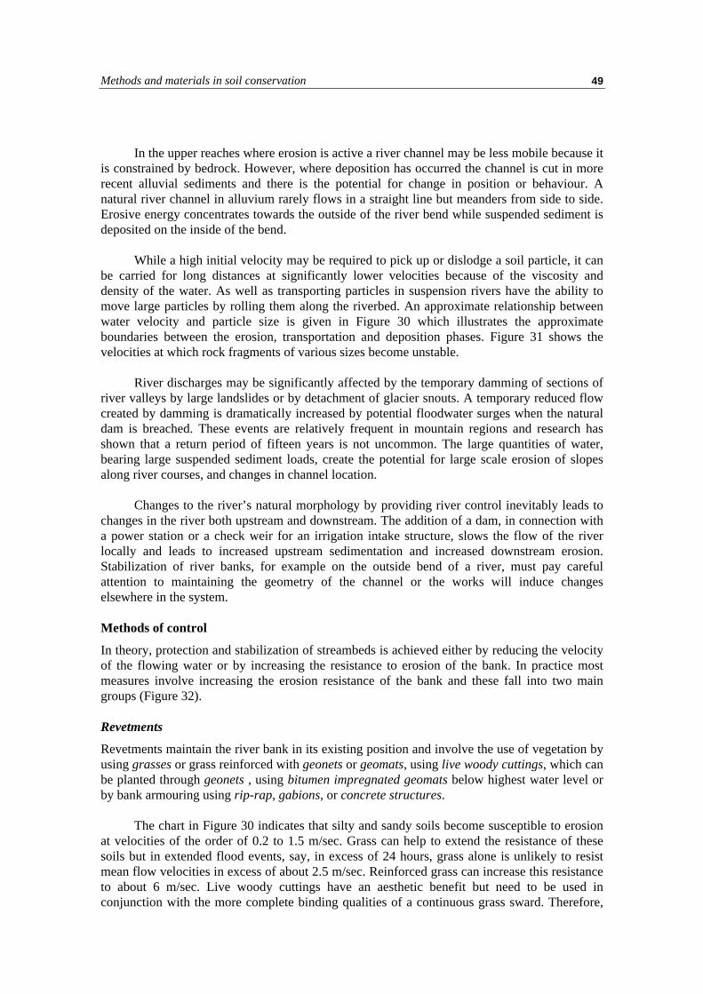
Methods and materials in soil conservation 49
In the upper reaches where erosion is active a river channel may be less mobile because itis constrained by bedrock. However, where deposition has occurred the channel is cut in morerecent alluvial sediments and there is the potential for change in position or behaviour. Anatural river channel in alluvium rarely flows in a straight line but meanders from side to side.Erosive energy concentrates towards the outside of the river bend while suspended sediment isdeposited on the inside of the bend.
While a high initial velocity may be required to pick up or dislodge a soil particle, it canbe carried for long distances at significantly lower velocities because of the viscosity anddensity of the water. As well as transporting particles in suspension rivers have the ability tomove large particles by rolling them along the riverbed. An approximate relationship betweenwater velocity and particle size is given in Figure 30 which illustrates the approximateboundaries between the erosion, transportation and deposition phases. Figure 31 shows thevelocities at which rock fragments of various sizes become unstable.
River discharges may be significantly affected by the temporary damming of sections ofriver valleys by large landslides or by detachment of glacier snouts. A temporary reduced flowcreated by damming is dramatically increased by potential floodwater surges when the naturaldam is breached. These events are relatively frequent in mountain regions and research hasshown that a return period of fifteen years is not uncommon. The large quantities of water,bearing large suspended sediment loads, create the potential for large scale erosion of slopesalong river courses, and changes in channel location.
Changes to the river’s natural morphology by providing river control inevitably leads tochanges in the river both upstream and downstream. The addition of a dam, in connection witha power station or a check weir for an irrigation intake structure, slows the flow of the riverlocally and leads to increased upstream sedimentation and increased downstream erosion.Stabilization of river banks, for example on the outside bend of a river, must pay carefulattention to maintaining the geometry of the channel or the works will induce changeselsewhere in the system.
Methods of control
In theory, protection and stabilization of streambeds is achieved either by reducing the velocityof the flowing water or by increasing the resistance to erosion of the bank. In practice mostmeasures involve increasing the erosion resistance of the bank and these fall into two maingroups (Figure 32).
Revetments
Revetments maintain the river bank in its existing position and involve the use of vegetation byusing grasses or grass reinforced with geonets or geomats, using live woody cuttings, which canbe planted through geonets , using bitumen impregnated geomats below highest water level orby bank armouring using rip-rap, gabions, or concrete structures.
The chart in Figure 30 indicates that silty and sandy soils become susceptible to erosionat velocities of the order of 0.2 to 1.5 m/sec. Grass can help to extend the resistance of thesesoils but in extended flood events, say, in excess of 24 hours, grass alone is unlikely to resistmean flow velocities in excess of about 2.5 m/sec. Reinforced grass can increase this resistanceto about 6 m/sec. Live woody cuttings have an aesthetic benefit but need to be used inconjunction with the more complete binding qualities of a continuous grass sward. Therefore,

Erosion mechanisms and methods of control50
for higher flows the choice becomes one of using stone in rip-rap or gabions. Resort to concretestructures should only be considered if design and maintenance resources are easily available.Rip-rap and gabion boxes can be planted with live wood or aquatic grasses which, besidesenhancing the visual appeal , can eventually help in binding and anchoring the stone structure.
Spurs and groynes
Spurs and groynes are structures that project into the riverbed from the bank to prevent lateralerosion.
The orientation of the spur in relation to the riverbank is important. If it is constructed atright angles (protection spur) it serves to protect the status quo. If it is inclined upstream
FIGURE 32Types of river bank protection works

Methods and materials in soil conservation 51
(aggradation spur), it encourages sediment to accumulate in the area between successive spurs.If it is inclined downstream (deflection spur) it deflects the stream flow to the opposite bank.
The spacing of successive spurs is also important to prevent erosion of the bank betweenthem. The separation distance is calculated using the following:
D = cot 150 * L = 3.73L
Where: L = length of the spurD = distance between spurs
Spurs interrupt flow and therefore water velocities increase around them causing localscour. Scour can also develop at the toe of revetments providing guide walls along a riverbank.Design against scour is imperative if the structures are to survive for their intended design life.The structures should ideally be trenched into the stream bed to a depth greater than thepredicted scour depth but this is practically often difficult. Alternatively a protective gabionapron should be laid on the streambed and incorporated into the structure to protect the toe. Aflexible apron moves the scour location away from the toe of the spur to the front of the apronwhich then deflects into the scour hollow (Figure 33) but maintains the integrity of thestructure.
FIGURE 33Scour protection function of a gabion apron

Erosion mechanisms and methods of control52

Methods and materials in soil conservation 53
Chapter 4
Mass movement and methods of control
MASS MOVEMENT
Mass movement often also referred to as mass wasting is a general term to describe thoseprocesses by which a large volume of natural earth and rock material becomes unstable andmoves as a mass under gravity. These processes are distinguished from other processes oferosion in which individual soil particles are displaced and transported. Mass movements orlandslides occur naturally where steep slopes are affected by climatic factors that causeweathering and an accompanying weakening of the soil or rock mass. These natural movementsare part of the landscape evolutionary process and are primarily associated, therefore, withmountainous regions.
Human activity also contributes to landslides and while mountainous regions are mostsensitive to human interference they can be triggered anywhere by an unplanned approach todevelopment. Typical causes of instability are changes to existing slope geometry, for exampleby creating an oversteepened slope when excavating for building, mining and quarrying, orroad construction. Changes in groundwater conditions are another major cause of slopeinstability when a local rise in the water table increases the pore water pressure in the slope.This may be initiated by obstructing drainage channels or by introducing an irrigation systemwithout adequate attention to accompanying drainage measures.
Landslide classification
Several landslide classifications exist. Comprehensive reviews of these have been made byHansen (1984) and Crozier (1986). The one used in this manual is based on Varnes (1978) andis presented in Figure 34. This classifies the slides on the basis of the nature of the movement.It is worth stating an additional distinction used in this manual for landslides, the landslidematerial has moved by translation along a surface which separates it from the original materialbeneath.
Varnes distinguishes between failures in rock and in soil. Rock fails by movement alongexisting discontinuities in the rock mass, such as bedding planes, joints or faults. Soil fails byinternal deformation, the shear strain increasing locally to form a shear plane along whichsliding takes place. Varnes identifies types of slope movement as falls, topples, slides(rotational and translational), lateral spreads and flows
Falls
Rockfalls occur where a steeply sloping rock face consists of closely-jointed rock. Thefragments become loosened by enlargement of the joints. This can occur through pressuregenerated by the growth of roots, by the freeze/thaw of water in the joint or just by gravity.Soil falls can occur in coarse-grained very weakly-cemented materials when the slope isoversteepened by undercutting. (Plate 4).

Mass movement and methods of control54
FIGURE 34Classification of landslides (from Varnes 1978)

Methods and materials in soil conservation 55
PLATE 4Soil fall in terrace depositsnear Gilgit, NW Pakistan
Topples
Topples are most common in rock slopeswhere the orientation of the discontinuities inthe rock mass is such that a forward topplingof individual blocks or groups of blocks canoccur. At least one set of intersectingdiscontinuities must be steeply inclined andthe dimensions of the individual blocks mustbe such that the centre of gravity falls outsidethe front toe of the block (Figure 35 andPlate 5).
Slides
Rotational slides
Rotational slides usually occur in soil or inrock masses that are so very closely jointedthat they effectively act as a granular soilmass. They are caused by the mass sliding, orrotating, along a circular slide plane. Theyoften leave an exposed slip scar behind the topof the slip mass which has an upper surfaceinclined back into the hillside. They can bevery deep (Plate 6).
Translational slides
Translational slides involve a down-slopemovement along a slide surface which isinclined and planar. They tend to be shallowerthan rotational slides, and are influenced byplanes of weakness that align approximatelyparallel to the slope surface.
FIGURE 35Toppling failure and conditions for it tooccur
Toppling failure
Flexural toppling
Condition for toppling failure

Mass movement and methods of control56
PLATE 5Slope subject to toppling failure, Sandwood Bay,Scotland
PLATE 6 Rotational slide in soil near Tongsa, Bhutan
Translational slides are often mostcommon in rock masses where the failure planeis provided by sets of joints orientatedconsistently in relation to the slope surface. Oneset of joints sub-parallel to, but dipping lesssteeply than, the slope provide the conditionsfor plane failure while two sets of intersectingjoints can result in wedge failure (Figure 36).
Flows
Slides in soil materials often turn into flows asdistortion takes place with the slidingmovement. A major factor influencing thetendency to flow is the water content and flowslides often obey the rules of viscous fluids.Debris flows are a common form of failurewhere a weathered surface zone has developedon steep rock slopes. The weathered materialslumps from the underlying less weatheredmaterial and spreads out to produce a large fanof slipped material at the base of the slope(Plate 7).
Factors that cause landslides
In simple terms landslides occur when the forces causing failure overcome the forces resistingfailure. The forces causing failure are typically gravitational. They increase if the slope angle issteepened at a constant height, or if the height of the slope is increased at a constant slope
FIGURE 36Plane and wedge failure in rock slopes

Methods and materials in soil conservation 57
angle. The main component of the forces resistingfailure is the shear strength of the slope material.The shear strength is decreased by weathering or bya change in groundwater conditions. Weatheringproduces chemical degradation in the materials witha corresponding decrease in their shear strength. Achange in groundwater conditions can increase thewater content of clay materials which decreases theirshear strength. A rise in groundwater level alsocauses an increase in pore water pressure whichdecreases the effective shear strength of thematerial.
The effect of external actions on an existingslope can therefore be appreciated. The geometry ofthe slope can be steepened by undercutting the baseof the slope. This may result from river action, or byexcavation. The slope may be surcharged fromabove by the addition of spoil material fromexcavation or from natural scree deposited fromfurther up-slope. Finally, earthquakes or otherdynamic transitory forces due to rail or road trafficcan also increase shear stress.
These factors can be aggravated by poor landmanagement practices. Irrigation, overgrazing, or deforestation on steep slopes can lead tochanges in the critical factors that govern slope stability.
METHODS OF STABILITY ANALYSIS
Slope stability analysis requires a knowledge of soil and rock mechanics and the help ofgeotechnical specialists should be enlisted for detailed assessments. However, there aremethods of preliminary analysis that can be used to define the scale of the problem and whichallow a conservative approach to be adopted in areas where the cost of additional labour andmaterials can be absorbed locally. This is often preferable to involving external specialists inmore sophisticated design and construction that may result in a solution that is difficult tomaintain with local resources. The basic approach to stability analysis is described below.
Choice of material parameters
The material parameters required for slope stability analysis are the unit weight (γ) and theshear strength (τ). The shear strength is expressed as:
τ = c′ + σ tanφ′ (see Figure 10)
where:c′ = effective cohesionσ = normal stressφ′ = effective angle of shearing resistance
PLATE 7Debris flow near Chatra, Nepal

Mass movement and methods of control58
A distinction between peak shear strength and residual shear strength parameters must bemade for overconsolidated cohesive soils and rock joints. The first time that a slope failureoccurs the shear strength of the previously unsheared material, or the peak shear strength, isapplicable. Once failure has occurred in these materials a lower strength applies to the materialalong the shear plane. This is the residual strength. When considering the residual shearstrength the cohesion is normally considered to be zero, while a lower angle of shearingresistance applies.
For detailed analysis the soil parameters would normally be measured in laboratory testsbut for the preliminary analyses described below the following values for the angle of shearingresistance can be assumed. For preliminary analyses the cohesion can also be assumed to bezero.
TABLE 82Typical values of the angle of shearing resistance for use in preliminary stability analysis
Material Angle of Shearing Resistance (φ) degreesCohesionless soils Loose DenseSand, single sized round grains 28 34Sand, well graded angular grains 33 45Sandy gravel 35 48Silty sand 27 30Inorganic silt 27 30Cohesive soils PI = 100 PI = 50 PI = 25Normally consolidated clay 21 25 30Cohesive soils Peak ResidualOver-consolidated clay 21 14Rock jointsHard Igneous Rocks
granite, basalt, porphyryMetamorphic Rocks
quartzite, gneiss, slateHard sedimentary rocks
Limestone, dolomite, sandstoneSoft sedimentary rocks
coal, chalk, shale
35 – 45
30 – 40
35 – 45
25 - 35
The role of groundwater
The role of groundwater in reducing shear strength is illustrated in Figure 10. The associatedpore water pressure (µ) causes a reduction in the normal stress and, therefore, a reduction inshear strength. The expression for shear strength (τ) is modified to become:
τ = c′ + (σ-µ) tanφ′
where: c′ = effective cohesionσ = normal stressφ′ = effective angle of shearing resistanceµ = pore water pressure
In descriptive terms the normal stress can be regarded as an overburden pressure that acts topush the soil particles closer together. The presence of groundwater within the pore spacesbetween the soil particles exerts a pore water pressure that acts to push the particles apart, inother words a type of buoyancy effect. The difference between the normal stress and the porewater pressure is the effective normal stress.

Methods and materials in soil conservation 59
The concept of Factor of Safety
The stability of a slope is measured in terms of the balance between the forces causing failureand the forces resisting failure. This is expressed in the Factor of Safety (F). When the shearingresistance is greater than the shearing force the Factor of Safety is greater than 1. The slopefails and a landslide occurs when the Factor of Safety drops to below unity, i.e. the shear forcehas exceeded the shearing resistance.
In slope stability analysis the Factor of Safety is calculated. The minimum figure fordesign is usually F=1.3 although this can vary on the basis of factors which include confidencein the parameters used and risk to the public. Where investigation is difficult and parametershave to be assumed a Factor of Safety of between 1.5 and 2 would be realistic. When a Factorof Safety is calculated which falls below the required value a method of stability control has tobe chosen and employed to raise the Factor of Safety to the required level.
Infinite slope analysis for a soil slope
Plane translational failures are often shallow, the depth of the slip plane being less than onetenth of the distance from the toe to the rear scarp of the slide. They are common forms offailure on steep slopes and are often caused by undermining during excavation. A simple formof slope analysis in this situation is the method of infinite slope analysis.
For the slope represented by the section in Figure 37:
Factor of safety (F) = Shearing resistance = τ Shearing Force T
=tantan
( )′ −
φβ
γ γγ
ss
sat w
sat
(if water level at slope surface)
=βφ
tantan ′ (if dry slope)
Failures in rock slopes
A convenient and rapid way to provide a preliminary assessment of the stability of a rock slopewhich contains one prevalent set of joints sub-parallel to the slope face or two prevalent jointsets which intersect to form a wedge is to use wedge stability charts (Hoek and Bray 1981).
If the cohesive strength is zero the factor of safety of the slope shown in Figure 38 isrepresented by the equation:
F = A.tanφA + B.tan φB
where φA is the angle of shearing resistance for plane A (shallowest plane)φB is the angle of shearing resistance for plane B (steepest plane)
A and B are dimensionless factors that depend only on differences in the dip angles and dipdirections of the two discontinuity planes. The values of these two factors, A and B, have beencomputed for a range of difference values and the results are presented as a series of charts inHoek and Bray 1981. An example of one set of these charts is shown in Figure 39. Theinterested reader is referred to the original publication for the full set.

Mass movement and methods of control60
FIGURE 37Idealized infinite slope
FIGURE 38Definitions used in wedge stability charts for friction only analysis of rock slopes

Methods and materials in soil conservation 61
FIGURE 39Wedge stability charts for friction only (Dip difference 60 and 70 degrees)

Mass movement and methods of control62
The following example illustrates the use of these charts:
Dip (degrees) Dip direction(degrees)
Angle of shearingresistance (degrees)
Plane A 40 165 35Plane B 70 285 20Differences 30 120
By turning to the charts for ‘dip difference = 300’ the values of A and B can be read offfor the dip direction difference of 1200. For these conditions A = 1.5 and B = 0.7
Therefore, F = A.tanφA + B.tan φB
= 1.5.tan 35 + 0.7.tan 20= 1.30
This preliminary ‘friction only’ analysis shouldbe used as a guide. If the factor of safety derived fromthis procedure is greater than 2 it can be assumed thatthe slope will be safe under the most adverse conditionsand no more detailed analysis will be necessary. A valueof less than 2 would require a more detailed analysis.Hoek and Bray 1981 should be consulted for moredetailed methods.
METHODS OF CONTROL
Regrading
Regrading a slope to a shallower slope angle providesthe means by changing the slope geometry toredistribute the stress that may be leading to potentialfailure. The shearing forces are therefore reduced. Inrural development projects in particular, theconstruction methods employed in slope excavationoften result in unstable slopes that otherwise wouldremain relatively stable. One of the reasons for this isthe failure to leave the slope with a regular slopeprofile, and another is the habit of cutting the slope facetoo steeply. On slopes of limited height the result isshallow failures or erosion of the slope face. In manycases this leaves an overhanging, undercut slope crestwhich is very prone to further erosion. This should becarefully rounded off (Figure 40).
A regular slope profile allows water to be shedeasily and prevents local ponding of surface water, whichcan cause a local rise in pore water pressure if allowed toinfiltrate the slope surface.
FIGURE 40Rounding off a slope crest
PLATE 8A slope crest that requiresrounding off

Methods and materials in soil conservation 63
Plate 8 shows a slope that has not been carefullyregraded and rounded off. This is only a small slope, butthe scar to the right of the little girl marks a soil slip thatblocked the drainage channel, caused the channel toovertop and the resulting erosion can be seen in Plate 9.
Drainage
Function
The main function for surface drainage is to improveslope stability by reducing infiltration during heavy orprolonged rain. It should collect runoff from thecatchment area upslope and from the slope itself. When aslope failure has occurred and been attributed to excesspore water pressure, drainage measures will also beneeded to reduce porewater pressure in the slope. Thisincreases the effective shearing resistance and thereforealso the Factor of Safety.
If a cut-off drain is required to divert runoff fromupslope the volume of runoff must be calculated to enablethe size of the drain to be determined.
Calculation of catchment runoff
Runoff from a catchment depends on rainfall intensity, the area and shape of the catchment, thesteepness and length of the slope, the nature and extent of vegetation and the soil type andcondition. An estimate of runoff volume can be calculated by using the following expression:
Q = KiA3600
where Q = the maximum runoff (litres/sec).i = the design mean intensity of rainfall (mm/hr) which is dependant on
time of concentrationA = area of catchment (square metres)K = runoff coefficient
To calculate ‘i’, the design mean intensity of rainfall, the time of concentration must firstbe determined. This is the maximum time taken by surface water to travel from the catchmentboundary to the point in the drainage system under design. The most remote boundary shouldbe taken, or several potential lines of longest flow should be assessed and compared. It iscalculated using a modification of the Bransby-Williams equation:
t = 0.14465 {L
H A0 2 0 1. ..}
where A = the area of the catchment, ‘A’, is measured from contour plans, and anyareas affected by existing drainage measures should be discounted.
‘H’ = the average fall (m per 100m) from the summit of the catchment to the pointof design.
‘L’ = the distance in metres on the line of longest flow from the catchment boundary to the design section.
PLATE 9Consequences of a small slopefailure at the location of Plate 8blocking the drainage channeland causing overtopping

Mass movement and methods of control64
The design mean intensity should be taken from curves showing intensity vs. duration ofrainfall for the area under consideration. Careful consideration of an appropriate return periodshould be made.
If ‘K’, the runoff coefficient, is set to 1, the runoff volume is simply the product of areaand intensity, with no allowance being made for mitigation by other factors such as vegetationcover described above. This will give an overestimate of runoff, particularly on vegetatedslopes, and result in an overdesign of the drainage system. This can be useful, nonetheless, inareas where siltation, debris blockage and irregular maintenance are common.
Design of cut-off drains
Where there is no discrete source of water above the slope, cut-off drains help to trap anydownslope flow from the surface and upper soil layers above the slope and direct it to anadjacent water course. If rainfall figures are available these should be used, together with anestimate of the catchment area upslope of the slip area, as described above, to calculate typicalwater flows that the drain will have to cope with. In tropical areas, where intense short durationstorms are common, it would not be unreasonable, as a worst case, to assume no infiltration ofsurface water. Figure 41 can then be used to decide on the appropriate size of drain that shouldbe used.
FIGURE 41Discharge capacities for open channels and circular pipes (after Blake 1975)

Methods and materials in soil conservation 65
Example: a catchment area of 2 hectares in a storm lasting one hour and subject to 25 mm ofrain would produce at the worst 500 m3/hour or 0.14 m3/sec. What size of cut offdrain laid at a gradient of 1:20 would be required to disperse this flow?
From Figure 41At a slope gradient of 1 in 20 a 0.3 m diameter pipe would be needed.
Diversion and training
Management of existing waterways is needed when they are blocked by landslide debris. Anexisting gully, for example, may need to be diverted to take the seasonal flow away from theslip area to an adjacent watercourse. Alternatively, the gully flow must be restricted to a clearlydefined channel through the landslip area and on into an undisturbed watercourse. In both casesthis will prevent this concentrated source of water from disgorging indiscriminately onto thelandslip mass and ponding, resulting in infiltration into the slope and a build up in pore waterpressure.
The dimensions of the new channel are best decided by duplicating the sizing of theexisting channel, which has evolved over time in response to local conditions. Any reduction insize would result in increased scour and the potential for the new channel to erode and causeadditional problems.
Surface slope drains
In general, groundwater drainage measures involve the placement of higher permeabilitymaterials into the in-situ soil to act as a preferential flow path for water. Increasing the flow ofwater out of the slope thereby reduces the pore water pressure in the slope. This may be actingon the potential critical failure plane, or the surface of sliding in an existing landslip.Employment of drains may prevent pore water pressures reaching a critical level to trigger alandslip or it may reduce pore water pressures to a level that slows down or stops existingmovement.
Trench drains are usually orientated to run downslope from top to bottom of the slippedmass. Herringbone patterns are often used to link oblique drains into larger downslopechannels. The spacing of the trenches is designed to reduce the groundwater to a specified leveland the concept is illustrated in Figure 42. It is beneficial in this case to design the depth of thedrain on the basis of Figure 42, check the capacity using Figure 43 and then add a separate freechannel depth above the gravel infill to carry the calculated run-off from the surface area of thelandslip mass using Figure 41.
Deep drains
Trenches can only be excavated safely to depths of 2 metres or less without support of thetrench sides or the use of machines. In deep slide areas, or areas where the pore water pressurein the slope is the result of deep springs it may be feasible to employ deep drains.
The cheapest form of deep drain is to drill from the base of the slope shallowly inclinedboreholes, inclined at a sufficiently steep angle to allow water to flow out of them but at ashallower angle than the angle of slope. These are often drilled in arrays that fan out from acommon drilling origin. Such drains can work very efficiently at first, but are difficult tomaintain and can rapidly silt up.
More expensive deep drains consist of vertical holes drilled to intercept the water tablewhich is then pumped by submersible pumps.

Mass movement and methods of control66
FIGURE 42Drain spacing for groundwater drawdown
FIGURE 43Discharge capacities for stone filled drains (after Cedergren, 1967)

Methods and materials in soil conservation 67
Filter design
The placement of high permeability, and therefore, coarse grained materials in contact with thefiner-grained in-situ materials requires the use of filters to prevent in-situ soil being carriedwith the water into the drains. This causes clogging of the drains so that they lose their functionand it can cause settlement of the ground surface adjacent to the drains.
If natural sands and gravels are used for filters they need to have a controlled particlesize distribution somewhere between the in-situ material and the drainage material. This allowsthe water to pass through freely while preventing the in-situ soil from passing through or‘piping’. The criteria by which such materials are chosen are illustrated in Figure 44.
D15 (filter) < 5 x D85 (in-situ soil) to restrict pipingD15 (filter) > 5 x D15 (in-situ soil) to satisfy permeabilityD50 (filter) < 25 x D50 (in-situ soil) to maintain grading
Therefore, once the particle size distribution of the in-situ soil is known the particle sizedistribution of a suitable filter can be determined. In many situations a series of successivelysized filters may be needed, for example when gabion retaining structures are being used at thetoe of a slope there may be a large discrepancy between the particle size of the in-situ soil andthat of the single size gabion stone.
In areas where resources and skills are limited the provision of materials meeting theabove criteria may be difficult. In these situations geotextiles can be advantageous. A singlelayer of geotextile used to line a trench or wrap a perforated pipe can be considerably moreefficient and labour saving than using conventional materials.
FIGURE 44Filter design criteria for natural materials

Mass movement and methods of control68
FIGURE 45Types of gravity retaining wall

Methods and materials in soil conservation 69
Retaining Structures
If an existing slope has to be steepened to allow a track, road or an irrigation canal to beconstructed across it and the new profile results in an unacceptably low Factor of Safetyretaining structures can be used to support the new steep cut slope or to support fill placedbehind them to carry the new road. While the initial cost is much higher than cutting anunsupported slope the long term costs are much lower in preventing long term instability andenvironmental degradation that can affect the hillside for many tens of metres both above andbelow the new construction.
Although many types of retaining structure are available, for the purposes of this manualonly gravity walls will be considered. Gravity walls are simple structures usually built ofconcrete or stone masonry and built to considerable thickness, relying only on the weight of thewall to resist the pressure exerted by the retained soil and therefore ensure stability {Figure45(a)}. If a heel is used at the rear of the wall then the thickness can be reduced because theweight of the backfill acting on the heel can provide the same stability.
There are two uses for gravity walls. The retaining wall is specifically designed tosupport the material it retains. The revetment or breast wall is used only to protect the materialbehind the wall from the effects of weathering which would result in degradation, loss ofstrength and the progressive onset of instability.
Types of gravity wall
The choice of building materials will be governed by local availability and cost. The methodwill often depend on local skills. Reinforced concrete and mass concrete walls are rigidstructures often unsuited to simple design, require specialised construction skills and are proneto distress under even small movements thus requiring skilled maintenance. Therefore, they arenot considered further in this manual. Drystone walls are simple to build with a local labourforce but are restricted in the height to which they can be built and require regular maintenance.Crib structures using interlinked timber or concrete stringers and ties to form a structuralframework encasing a fill material {Figure 45(b)}and gabion structures that use wire baskets,usually 1m x 1m x 2m in size, filled with stone {Figure 45(c)} are common. Gaining popularityare reinforced earth structures that re-use the excavated soil material and add reinforcingelements to strengthen it {Figure 45(d)}.
Design
The design of gravity retaining walls requires the following conditions to be satisfied:
• the structure should not overturn about the toe• the structure should not slide forward on its base• the structure must not exceed the bearing capacity of the foundation soil• the earth pressure generated behind the wall should not overstress any part of the
structure• the general stability of the soil around the structure should be maintained
In the design process an initial dimension is normally chosen on the basis of tables thatgive typical base width to height ratios for various wall types. The magnitudes of the forcesacting on the base of the wall, the major ones result from the weight of the wall and thepressure of the backfill, are estimated and the resultant should fall in the middle third of thewall base. The adequacy of the foundation soil to support the wall and to prevent sliding is then

Mass movement and methods of control70
checked. Detailed methods of analysis are outside the scope of this manual but guidelines todesign and construction based on experience are presented below for the main wall types. Thefollowing descriptions treat the walls in ascending order of cost.
Drystone walls
Drystone walls offer a cheap and easy to build solution in rural areas. However, they are likelyto be the least durable form of wall. The durability is directly linked to the skill and caredevoted to the construction. Care in the following aspects of construction will considerablyimprove their performance:
• Excavation for placing the base of the wall should be extended to a firm foundation.• It is preferable to slope the base back into the slope at about 10°.• Drystone walls should not be higher than 3.5 m.• The width of the base (front to back) should be at least half of the height.• Only strong unweathered and angular stone (‘rings’ to the hammer) should be used.• The stone should be carefully packed to maximise interlocking between individual
pieces.• Preferably the stone should not be equidimensional and should be packed with the
longest dimension extending back to front into the slope.• Any gap between the slope and the rear of the wall should be hand-packed with granular
material.
A variation sometimes seen is to introduce bands of cement bonded masonry at regularintervals of height. This can allow the overall height to be increased. Typically, in Indian Roadpractice for example, the masonry bands are up to 0.6 m thick and placed at intervals of about1.5 m. Heights up to 12 m have been attempted, but the author would not recommend more than6 m without detailed analysis.
Reinforced earth
Reinforced earth comprises a series of compacted soil layers separated by sheets or strips of areinforcing medium, which may be a sheet geotextile, a sheet of woven gabion wire, a timbergrid, or metal strips.
A sub-vertical structure , face slope angle greater than about 70o, is generally referred toas a reinforced earth retaining wall and can be built from reinforced soil if facing units are usedto hold the soil in place. For slopes with an angle of less than 70o it is possible to use ‘soft’facings, such as soil filled jute bags, to form the face of the slope and the natural soil iscompacted behind this face. For slopes of less than about 45o no special facing is necessary butvegetation should be established soon after construction {Figure 45(d)}.
The most effective use of reinforced earth in situations for which this manual is written isto use the reinforcement to enable a slope to be built at a steeper slope angle than can beachieved without such reinforcement. In areas where the potential for landslides is to beavoided or mitigated, particularly where new construction in steep ground has to be carried outor where a landslip has to be repaired then reinforced earth is an effective and economicconstruction technique.
Without reinforcement, soil has a low tensile strength. When it is surcharged it flattensand widens, undergoing lateral tensile strain. With reinforcement in place the lateral movement

Methods and materials in soil conservation 71
will only take place if the shear strength of the interface between the soil and the reinforcementis exceeded (so that there is slippage between the soil and the reinforcement) or if thereinforcement ruptures. The system therefore relies on the frictional strength between the soiland the reinforcement.
The detailed design procedures depend on the material used for the reinforcement andeach manufacturer provides design notes or offers a design service for his particular product.The interested reader should contact manufacturers for more detailed information.
The following procedure should be adopted for reinforced earth construction (Figure 46).
• The slope is excavated to a firm foundation and an initial sheet of reinforcement material islaid by rolling out the sheet from the back to the front of the slope.
• The soft facing is placed and the reinforcement is cut leaving a margin of materialextending forward of the face.
• A layer of soil is placed and compacted behind the facing.
• The extended sheet is then brought up around the facing and laid back onto the top of thesoil layer.
• A new sheet of reinforcement is laid from the back to the front of the new upper soil layerand the lower layer is lapped and joined to it.
• The next soft facing is placed.
• The steps above are repeated until the final height is achieved.
FIGURE 46Construction sequence for reinforced earth

Mass movement and methods of control72
Gabion walls
Gabions are boxes or mats formed out of wire mesh and filled with durable stone. Structuresare formed by linking the boxes. Gabion boxes and mattresses can utilise local resources ofstone and they can be readily built with local skilled and unskilled labour. They are flexible andcan accommodate movement and they can be maintained and repaired by the local workforce.The only import is the wire which can be supplied ready woven into mesh panels, or weavingcan be carried out locally.
There are several basic rules that must be followed for gabion construction to ensure thatthe gabions form a durable and sustainable function. They are particularly vulnerable to poorconstruction practice.
The gabion stone should be ideally between 100 mm and 200 mm in size and shouldnormally be at least 1.5 times the size of the mesh. Where stone of adequate size is difficult toobtain then stone no smaller than the mesh size can be used provided it is not immediatelyadjacent to the mesh. Stone should be hard and durable and may be from a quarried source ornaturally occurring rounded river stone. Because river boulders have been subjected to a historyof attrition from the river they are generally very durable. However, they are also rounded andattention should be paid to using variable sized stones to pack the voids between the largerstone. Quarried stone is more angular and hand packing can achieve a particularly soundstructure. Gabion construction and packing is illustrated in Plates 10 and 11.
PLATE 10Packing stones into gabion boxes
PLATE 11An example of a well-packed gabionbox

Methods and materials in soil conservation 73
The strength of the stone has been specified in UK by a minimum ten-percent fines testvalue of 50 kN. In the absence of test facilities a useful field test for durability is to tap the rockwith a hammer; a ‘ring’ indicates suitable material, a ‘thud’ indicates weak and weatheredmaterial.
The gabion wire should be at least 2.5mm in diameter and should be woven into ahexagonal mesh, 80mm by 120mm, as shown in Figure 47. It is important, particularly insituations where abrasion will occur, e.g. in river protection works, that the wires forming themesh are double twisted so that if a wire is broken it is prevented from unravelling andprogressively weakening the structure. The mesh is formed into panels usually either 0.5m or1m by 1m, 1.5m, 2m, 3m, or 4m, or into rolls 2m to 4m wide. The panels or rolls are reinforcedat the edges by a ‘selvedge’ wire thicker than that forming the mesh, typically at least 3mmdiameter, and which is bound into the mesh.
In rural locations with limited facilities and cost constraints there is a temptation to usethinner wire, to use a single twist square mesh or to use a selvedge wire of the same thicknessas the mesh wire. Any of these measures should be resisted as they will reduce strength anddurability and lead to a considerably shorter service life.
Gabion construction aspects are illustrated in Figure 48. The gabion boxes are formed bylacing the mesh panels together using a lacing wire of at least 2 mm diameter. The lacing iscarried out from the corner in a continuous operation using alternate single and double twists ata spacing of between 100 mm and 150 mm.
The boxes should be placed on a prepared flat surface, sloping back into the slope at 10°
and preferably keyed into the ground to a depth of at least 0.5m. Each box should be laced to alladjacent boxes. 1m high boxes should be filled with stone to a third height (300 mm), and 0.5mhigh boxes to a half height (250 mm), before horizontal bracing wires are fixed from front toback at a lateral spacing of 500 mm. A further set of bracing wires are fixed at two-thirds heightin the 1m boxes. When full, generally 50 mm to 75 mm above the top of the box to allow forself settlement, the lid is added and laced to the walls.
FIGURE 47Weaving gabion mesh

Mass movement and methods of control74
FIGURE 48Gabion construction

Methods and materials in soil conservation 75
Masonry walls
Masonry walls may give the impression that they offer a more substantial retaining solutionover both drystone and gabion construction. However they are more costly and requireconsiderably more attention to drainage. Because they form a barrier to water flow they must bebuilt with an adequate number of weep holes to prevent water pressure building up behind thewall. In addition a permeable granular backfill is essential, together with drainage beneath thebase of the wall. In rural applications a considerable disadvantage is their rigidity. Smallmovements of the surrounding ground will result in cracking of the mortar and loss of integrityof the wall.
General construction methods
Topsoil and vegetation
Prior to new development an evaluation should be made as to whether the existing vegetationcan be preserved. If there is no alternative but to remove it then consider carefully whether thiscan be transplanted elsewhere on the site or whether it can be used as a source of plant material,e.g. live cuttings, for use elsewhere. Topsoil should be removed and stockpiled separately fromother materials so that it can be used again.
Excavation methods
Attempts should always be made to try and balance the quantity of excavated material with thequantity required for filling. On sidelong ground the construction of a level platform willrequire cutting into the slope and using the material to fill onto the slope below. The choice ofcross-section should be influenced by excavation and fill volumes, and cost and environmentalbenefits will be gained by adjusting the layout so that the material that needs to be excavatedcan be balanced to the material required for fill within the section.
Before making a cutting into the natural ground profile an assessment should be carriedout to determine the angle to which the newly formed slope can be cut. This will ensure that thenew work does not cause major instability. Detailed methods of assessment are beyond thescope of this publication, but some general rules apply.
In soil materials slopes cut at an angle of more than about 34 degrees (1v:1.5h) are likelyto slump. The higher the slope face, the more likely this is to occur. Whatever the slope anglethe cut profile should be smooth and regular, leaving no irregular humps. Revegetation methodsshould be considered immediately after excavation.
In rocks with suitable rock quality and geological structure an angle of 76 degrees(4v:1h) normally satisfies economic considerations while not appearing to be too overhanging.It is extremely important to cut to a smooth and regular profile and not to leave loose surfaceblocks. Blasting should only be carried out if the equipment is available to carry out pre-splittechniques since these provide a smooth profile and minimise damage or loosening of theresidual slope face.
Fill Placement and Compaction
Fill placement should be controlled. The material to be used should be graded to ensure that itis either sensibly single-sized or contains a sufficient range of sizes for successively smallerpieces to fill the voids between the larger sized materials. The ideal grading curve is based on

Mass movement and methods of control76
the Fuller-Talbot principle which produces an optimum shape for high density, working from achosen maximum particle size and using the proportioning rule.
Percentage passing any sieve = 100* square root (Aperture size of that sieve/size of largest particle)
Sloping ground should be benched before new fill is placed. The fill should be placed inlayers and each layer tamped or compacted before the next layer is placed.
Construction on sidelong ground
On sidelong ground the excavated material is frequently side tipped at the same locationcausing unsightly scars on the hillside which are often a source of continuing instability foryears to come. The development then straddles part cut and part uncompacted fill and at bestsuffers differential movement and at worst a catastrophic slip at the fill/cut boundary. Often theonly option to provide a measure of long term stability is to provide a retaining structure belowthe route alignment behind which the excavated material can be placed in compacted layers.
Roads or other linear projects traversing sidelong ground must take care to provideadequate crossing points for all existing drainage courses.
Spoil disposal
Sometimes it may prove impossible to sensibly balance cut and fill volumes and there will be asurplus of material to be disposed of. Ideally this should be dispersed in small loads over a widearea, it should not be randomly dumped in large quantities onto the slope face below theconstruction area. In particular, existing water courses must not be impeded. Either of the lattertwo practices will result in excessive local erosion which may develop to affect large areas ofthe catchment below the construction area.

Methods and materials in soil conservation 77
Chapter 5
Materials for erosion control
NATURAL STONE AND ROCK
In the developed world stone and rock materials for construction are readily available inprocessed form for almost any application. They can be supplied single sized or graded into amixture of sizes to be used as aggregate for concrete or roadstone, as filter materials or as finer-grained products for mortar. Moreover, sufficient producers exist to enable such materials to beprocured locally.
In the developing countries it is essential that materials for any application are availablelocally. Typically the suitability and availability of materials have to be investigated at sourceswhich have not been previously exploited. Materials won from such sources have to beprocessed locally to suit the required application.
This chapter describes the materials typically used in erosion and landslide control, themeans by which their quality can be assessed and the processing methods available to changethem from a raw material to a useful product.
Sand, gravel and stone for use in construction are available either from unconsolidateddeposits of sand and gravel or from rock outcrops. In the latter the rock has to be ripped orblasted to produce fragments that are then crushed ready for processing to the required size. Inthe former only processing is required. For both types of resource a similar philosophy appliesto the programme of investigation required to assess the potential quantity and quality of thematerial.
Source selection and evaluation
Initial studies
The initial selection of a material source will involve an inspection of geological maps to showthe distribution of suitable alluvial deposits as sources of sand and gravel or the area of outcropof suitable rock types as a source of crushed material. Alternatively, gravel pits or rock quarriesmay already exist in either an abandoned or working state which will give an indication ofpotential source areas. Topography and the presence of groundwater will dictate the quarryplan, and access to local roads or paths and the distance to the point where the processedmaterial is needed will be important considerations in the selection process.
Occurrence
Most sand and gravel deposits are found in river channels and their associated valley floors.They are the product of erosion by rivers, the water having transported weathered rock materialaway from its source. In the process, attrition between particles and the washing effect hasremoved the weaker and softer components and the remaining materials are often hard and

Materials for erosion control78
durable. The long exposure and transportation in water means that these deposits usually have arounded shape.
In the upper courses of rivers, where the valleys are narrow and V-shaped, there is lessopportunity to find large expanses of sand and gravel because in these sections the watervelocity is high and the materials remain in suspension to be carried further downstream.However, in seasonal climates gravel banks are often exposed in the dry season when waterlevels are low.
In the lower river courses, the river valleys are wider and there is generally a floodplainbordering the present-day river channel, or there is a braided river channel with manyintervening sand or gravel bars. Here, often over many years, the channel meanders or movesacross the valley floor and the whole of the bottom of the valley may be a source of sand andgravel. In the dry season it is comparatively easy to drive a truck and mechanical digger into theriver channel and exploit the materials, which are then renewed by natural river action in thenext wet season. The materials usually comprise a range of grain sizes, already mixed, andthese can provide a source of low-grade fill or aggregate material with minimum additionalprocessing.
Field Investigations
Once a site, or several potential sites, have been selected they should be investigated in moredetail to determine the lateral extent and variation in thickness of the material, and the presenceof other unsuitable material that may have to be removed to waste to enable the target materialto be exploited. The position of the groundwater table is also important as is the bulkcomposition of the material. Field investigations usually comprise a series of hand or machinedug trial pits, or a series of drill-holes. These should be logged, and a representative range ofsamples should be selected for laboratory testing.
In developing countries drilling equipment may not always be available and a portable andcheap alternative for certain situations is shallow geophysical investigation using resistivity orseismic refraction methods.
Thickness of overburden
Perhaps the most important factor will be the depth, nature and thickness of overburden, thematerial overlying the useful material which will have to be excavated and maybe discardedbefore the useful stone can be won.
In rock quarries the thickness of the overburden will be influenced by climate, whichinfluences the depth of weathering. In temperate and colder regions, and in arid zones, theoverlying soil cover may be thin but weathering effects may have increased the frequency ofnatural discontinuities. In tropical regions the combination of high rainfall and temperatureinduces humid conditions ideal for the chemical breakdown of the rock to form thick covers ofweaker material under a residual soil cover. A representation of a weathering profile is given inFigure 6 although local variations in joint patterns, slope steepness, etc, will influence thisgeneral representation.
In alluvial deposits the sand and gravel horizon may be covered by a deposit of finergrained silty or clayey material, or layers of such material may be present within the sand andgravel horizon.

Methods and materials in soil conservation 79
Natural block size
An important consideration in rock exploitation is the distribution of the natural block sizes.This is particularly important when the stone is to be used for masonry, dry-stone or gabionwalls, or for armour-stone in river or beach protection works. The natural block sizedistribution will depend on the frequency and spacing of discontinuities, i.e. the bedding andjointing, and can either be determined by inspection and mapping or be mathematicallydetermined (Wang, Latham and Poole, 1991).
The larger the required size of stone for the end-product the more critical is theevaluation. For example, if the product is an aggregate derived by crushing and then sizing thecrushed product, the discontinuity spacing may be irrelevant and a highly fractured rock massmay be suitable for exploitation. Some variation in the quality of the source rock may betolerable because the inferior material may be discarded in the processing. However, if therequirement is for, say, 8 tonne blocks of rock for armourstone both the natural block sizedistribution, the degree of weathering and the strength and durability properties of the in-situmaterial assume greater importance.
If crushed aggregates are to be produced from gravel sources the size of the cobbles andboulders is also important. In roadstone applications an angular shape is important to improveinterlock between fragments, but natural gravels are generally rounded. To ensure that angularfragments are produced it is often specified that a minimum size of natural gravel must be fedto the crusher, and this is often of the order of twice the required maximum size of the finalcrushed product.
Groundwater
In sand and gravel deposits, in particular, groundwater is often present at shallow depth.Extraction costs increase markedly if excavation has to take place below the water table, and itis important to determine during the initial studies the depth of groundwater and the seasonalchange in depth. If a trial pit investigation is undertaken the depth of the pits is often restrictedby the presence of groundwater and this gives a direct indication of the easily exploitable depthof the deposit. If drill-holes are used then it is important to measure the depth of the water tablein the holes during drilling, and to use certain holes for monitoring to establish a longer termrecord.
Planning and environmental issues
When considering the quarrying of stone or digging of sand and gravel it should beremembered that it may be necessary to obtain a permit from the appropriate authority, andmake a purchasing or leasing arrangement with the existing landowner. There may also beenvironmental regulations to consider and these may relate, for example, to increase in traffic,noise, blast vibration, dust, ground or surface water contamination, and loss of wild-life habitat.
Stability of the excavation
The majority of extraction sites involve excavation into an existing slope or the creation of ahole in the ground surface. In either case the stability of the excavation sides needs to beconsidered. In most cases the stone that is of sufficient quality for use in construction will becovered by weathered material that will be discarded.

Materials for erosion control80
The stability of slopes in weathered overburden material in rock quarries and the sides ofsand and gravel pits will depend on their shear strength. In rock the stability of the side slopesis governed by the discontinuities (faults, joints and bedding planes) in the rock. The effect ofthese depends on their frequency, orientation in relation to the slope face, tightness and surfaceroughness, nature of infill material and groundwater. Discontinuities are generally planar andgroup into sets of similar characteristics. At any location it is probable that three or more setsmay be identifiable. It is the relationship between these sets and the slope that governs thestability of the slope.
Slope stabilisation methods have been described more fully in Chapter 4.
Desirable properties for stone and aggregate
The strength and durability of stone is related to its petrography, or mineral composition. If amaterial source has been widely used locally this is a good indication of its general suitabilityand also gives the opportunity for more detailed inspection of its performance. If previoususage of the material is not evident then a testing programme needs to be established to provideinformation on the properties necessary for the intended use.
It is beyond the scope of this publication to examine in detail the required properties forparticular end-uses. However, certain requirements are universal and these are discussed below.
Size, grading and shape
Natural aggregates from sand and gravel and crushed aggregates from rock need to beprocessed to enable them to meet size and grading requirements. Coarse and fine aggregates aredifferentiated as greater or less than about 5mm and are usually stored separately. Crushedaggregates are usually processed into separate stockpiles of nominally single sized material.These are then blended to meet the particular size specification governing the end use of theproduct.
Coarse aggregates and sand are mixed to provide an overall grading that gives a low voidcontent per unit volume. The grading is usually specified in terms of a grading envelope limitedby maximum and minimum values. This plots the cumulative percentage of material passingeach sieve size and a typical grading envelope is presented in Figure 49. The actual gradingshould fall between and be sensibly parallel to the limiting curves and is a compromise betweenthe ideal and what is achievable given the size range of the source material.
The actual requirement depends on end-use. For example, the grading of a concreteaggregate is derived to provide good ‘packing’ and , therefore, strength together with theminimum cement and water content. An aggregate for use in a road pavement layer, however,may be sized to provide a higher void content, which is filled with bitumen, so that the coarseaggregate particles do not contact each other and abrade under the constant action of traffic.
The maximum size is also important and is determined by the thickness of the layer. If alayer of road aggregate is to be laid to a thickness of, say, 100 mm the maximum size ofaggregate particle would normally be limited to less than half of 100 mm, the layer thickness.This helps to prevent edge to edge contact between the aggregate pieces, which couldoverstress them, and also helps to prevent segregation of sizes during the spreading and layingof the material.

Methods and materials in soil conservation 81
The shape is also important in resisting deformation. Generally specifications require thatthe aggregate pieces are not unduly elongated or flaky, which makes them more susceptible tofracturing and hinders a good packing between adjacent grains. The length and/or width shouldnot be excessively greater than the depth. The shape can be influenced by the original texture ofthe rock, but if it is relatively unweathered this will be a secondary influence to the quality ofthe crushing process. Ideally aggregate particles should be angular as this helps to provideinterlock and better strength and any one dimension should not be more than twice any other.
In many parts of the world hand crushing is still commonplace and, while production isslow and uniform sizing is difficult to achieve, the shape and angularity is seldom a problem.The greatest cause of poor shape is poor crusher maintenance.
Relative strength and durability
It is important that an aggregate material does not disintegrate or degrade during its design life.It has to be strong and durable enough to resist breakage and abrasion during the handlingchain, i.e. transportation, processing, mixing with cement or bitumen, placement and end use.Some widely used tests to determine the strength and durability of aggregates are given inTable 9.
Aggregates, particularly when used in roadstone, need to demonstrate several desirableproperties. They need to be resistant to slow crushing, (Aggregate crushing value, Ten percentfines value), and to impact (Aggregate impact value, Los Angeles abrasion value). They alsoneed to be resistant to weathering effects, such as frost action or softening and degradation inthe presence of water, (Water absorption value, Soundness test)
FIGURE 49A typical grading envelope for aggregate

Materials for erosion control82
TABLE 9Some widely used tests for strength and durability of aggregates
Name of Test Designation DescriptionUSA
Los Angeles Abrasion Value
Soundness Test
ASTM C131, C535
ASTM C33,C88
Measures the amount of fines producedafter tumbling pieces of aggregate with anumber of steel balls
Measures the disintegration of aggregateafter wetting, heating and drying cycles ina sodium or magnesium sulphate solution
UK
Aggregate Crushing Value (ACV)
Aggregate Impact Value (AIV)
Ten per cent fines Value
Aggregate Abrasion Value (AAV)
Water Absorption
BS 812
BS 812
BS 812
BS 812
BS 812
Measures the amount of fines produced bycrushing an aggregate mix under aspecified load, slowly increased.
Measures the amount of fines produced byan impact loading
Measures the load required to produce thespecified amount of fines
Measures the loss in weight due to aspecified amount of abrasion
Indirect measure of the porosity ofaggregate and its propensity to absorbwater
Simple field assessments
In rural development projects the facilities are often not available to allow a detailedassessment of aggregate quality. However the principles discussed above can be applied byusing simple field techniques and an element of common sense.
An idea of the strength and durability of stone can be achieved by simply hitting thestone with a hammer. A ‘ring’ indicates that the stone is sound and usable. A dull ‘thud’ is anindication that the stone has internal flaws or is too weathered to be considered.
An alternative test was developed in South Africa by Netterberg (1971,1978). It isparticularly useful if materials are considered on visual inspection to be marginal in terms oftheir strength and durability. Between 100 and 200 pieces of the broken stone between 12 and20 mm in size should be selected. First, attempts should be made to break each piece betweenthe thumb and forefinger. The number that are broken are recorded as a percentage of the totaland these are set to one side. The remaining unbroken pieces are then tested by attempting tobreak them between the jaws of a pair of 180 mm pliers. The number that are broken are alsorecorded as a percentage of the total. These are termed the ‘aggregate fingers value’ and the‘aggregate pliers value’.
Shape can be successfully controlled by visual inspection. Maintaining a suitable gradingfor an aggregate mix is more difficult. The grading envelope given in Figure 49 is a typicalexample that will serve reasonably well in most circumstances. The most important factor is toensure that the curve for the aggregate mix is sensibly parallel to the envelope.

Methods and materials in soil conservation 83
EXTRACTION AND PROCESSING
This section describes simple extraction and processing methods applicable to developmentsituations where construction is likely to be labour intensive and stone is required in relativelysmall quantities. For this reason mining, i.e. underground, methods are not considered. The firstrequirement is for a plan to be developed to decide on the stability considerations and the typeof processing required (Figure 50).
Rock mass classification for prediction of excavation method
The classification of the rock mass is important to enable the ease of excavation to be predictedand to determine the natural block size of the material. Where the natural block size coincideswith the required stone size, excavation may be by mechanical techniques such as ripping orthere may be a need to resort to light blasting but the energy imparted should only be sufficientto loosen the rock and not fragment it.
When the requirement is for fragmented rock to feed on to other processing facilitiesthen there may be a need for blasting. The choice of ripping or blasting depends on the spacingof the discontinuities, the intact strength of the rock and the size of available machinery. Theseismic velocity measured in the field by seismic refraction surveys is influenced by strengthand discontinuity spacing and therefore as a single parameter can be a useful indication of thepotential excavation method.
Several classifications have been produced which relate the discontinuity spacing, thestrength and the seismic velocity to allow the probable method of excavation of a rock mass tobe determined (Franklin et al., 1971, Fookes et al., 1971, Caterpillar, 1990, MacGregor et al. ,1994, Pettifer and Fookes, 1994). An example of a classification chart is given in Figure 51.
FIGURE 50Extraction and processing plan for stone production
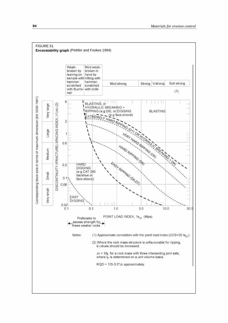
Materials for erosion control84
FIGURE 51Excavatability graph (Pettifer and Fookes 1994)

Methods and materials in soil conservation 85
Ripping
Ripping is a relatively cheap method of excavating rock where the material is soft or possessesmany discontinuities. A crawler tractor or a bulldozer is fitted with one or more steel tines orrippers behind the unit which are dragged and thus rip the rock.
Pre-split blasting
An important aspect of blasting that should be employed whenever there is a need to provide asmooth final face free of blast damage is presplitting. All too often existing quarry sites arebounded by high slopes of irregular profile and comprising extensive loose and blast damagedrock. Presplitting is also a very useful exercise to provide blocks to a specified size.
In presplitting, a series of small diameter closely spaced holes are drilled along the lineand at the angle of the required slope face. Typical diameters are 50 mm to 75 mm and spacingsare 600 mm to 1000 mm. These holes are located behind the primary blast area and form aboundary line between this area and the as yet undisturbed rock mass. They are lightly chargedand are fired before the main fragmentation charges, which may be detonated within the samefiring sequence but with a built in delay of at least 50 millisecs. The presplit fracture intersectsthe shock wave from the primary blast thereby producing a smooth face and protecting theremaining rock mass. The presplit blasting method is illustrated in Figure 52.
Sizing
The initial blasting or ripping operation will produce blocks that may be oversized for theenvisaged use and selection and processing methods will be needed to produce material that isof the required size and grading for the job in hand.
The largest sizes may be moved by face excavator and stockpiled for specific use or forsecondary breakage. Initial screening of the unsorted material can be achieved by passing itover a static grid or grizzly. This comprises a sloping grid of parallel steel bars of the order of200 mm spacing. The oversize flows across the grid while the undersize passes through it forfurther sorting on vibrating screens or for crushing.
Secondary breaking
Reduction in size of oversize material can be carried out by further blasting. ‘Popping’ involvesthe drilling of a blasthole into the rock boulder and placing a small charge. Plaster shootinginvolves the packing of a small charge against the surface of the boulder. Alternatively a dropball or hydraulic impact hammer can be used.
GEOTEXTILES
Function
In soil conservation geotextiles have three main roles.
• They can be used in slope protection. This may be by acting as temporary protection forvegetation on steep slopes, and degrading as the vegetation develops and establishes itself.Alternatively, they may provide a more permanent key to allow the placement of a soillayer on the slope face into which vegetation can be planted.

Materials for erosion control86
• They can be used as separators to prevent mixing of one soil type with another. This isusually achieved by providing a barrier to migration of particles between two soils ofdiffering grain-size while allowing free movement of water. An application in this respectmay be use as a separator between a gabion or rock boulder scour protection layer and theunderlying natural soil.
• They can be used for soil reinforcement to allow soils to carry a greater shear loading thanthey would otherwise be able to. By incorporating geotextile layers into a compacted fill
FIGURE 52Principles of pre-split blasting (Hudson 1989)

Methods and materials in soil conservation 87
the resulting reinforced soil structure may act as a retaining wall to mitigate against slopeinstability, may effect a repair to a previously slipped area, or may allow the initialconstruction of a steeper slope than would otherwise be possible.
The use of geotextiles in the applications above allows the re-use of local soils readilyavailable at the site. Transport and material costs (with the exception of the geotextile itself) aretherefore reduced.
It should be emphasised that geotextiles only improve the mass stability of a slope whenthey are used as part of a reinforced soil structure. When used as separators or in surfaceprotection they have no influence on the mass stability of the slope and this must be separatelyconsidered and ensured if cost and effort inherent in their use is not to be wasted.
Materials
A wealth of proprietary brands of geotextiles are available and they can be classified on thebasis of their material type and process of manufacture (Ingold and Miller 1988). They can beclassified into two main types on the basis of their composition.
Natural Fibres
Natural fibres have the tendency to rot, particularly under moist conditions, and thisbiodegradability can be used to advantage when such materials are used as a temporary minorstrengthening or protective measure until natural vegetation has grown to take over the role.The use of natural fibres is usually restricted to a bioengineering role, and they are almost neverused as reinforcement unless no other alternatives are available.
Plastics
Plastics are increasingly used where the strength or function of the geotextile is required to besustained over a long period. Synthetic geotextiles are manufactured from thermoplastics whichcan be softened and rehardened, making them an ideal base material from which to fabricate arange of products. Examples of thermoplastic polymers used in geotextiles are polyamide(nylon), polyester (terylene), polyvinyl chloride (PVC), polypropylene and polyethylene.
The polymers are generally formed into one of three basic component types:-
• a continuous filament, of circular cross-section a fraction of a millimetre in diameter• a continuous flat tape, a fraction of a millimetre thick and several millimetres wide• a sheet or film , a fraction of a millimetre (film) to several millimetres (sheet) thick and
several metres wide
The components are used to manufacture the finished geotextile product. Filaments may beused as single monofilaments, or in parallel aligned groups as multifilaments, or twisted intoyarn. Flat tapes may be used singly, or twisted into a tape yarn. Sheets may be punched andstretched to form grids exhibiting directional strength or strain resistant properties. Theseproducts tend to group into the following categories:-
• conventional weaving using combinations of monofilament, multifilament, yarn, flat tape ortape yarn produces a variety of woven geotextiles in the form of sheets typically about onemillimetre thick and displaying a mesh of reasonably single sized regular pore openings

Materials for erosion control88
• if monofilaments are cut into short lengths and then laid to form a loose layer of randomlyorientated pieces they can be bonded by mechanical, thermal or chemical means to producenon-woven geotextiles in the form of sheets or three-dimensional mats of variable pore size.
• geomeshes, geonets and geogrids have large pore sizes in comparison to the dimensions ofthe material. Meshes and nets are formed by bonding two orthogonal sets of tapes whilegrids involve the punching out of holes in a sheet. If, after punching the holes, the sheet isextended at an elevated temperature in the main load-carrying direction this improves thestrength and stiffness properties of the geogrid in this direction.
Role of geotextiles in surface protection
Slope Protection
Slopes and banks without a protective vegetation cover are open to the scouring effects of windand water, particularly if the exposed soil is sandy in composition or comprises a heavilyweathered and fractured rock. If the mass stability is satisfactory then aesthetic remediationusing vegetation is preferable to man-made protection structures such as stone pitching, gabionrevetments, etc. However, in these instances it can be extremely difficult for natural vegetationto re-establish itself. The use of geotextiles in conjunction with vegetation can provide earlyprotection as the vegetation establishes itself.
Geomeshes, geomats or geomatrixes
Geomeshes (two-dimensional) and Geomats or Geomatrixes (three-dimensional) are used tointeract with young seedlings by providing a stable surface through which seedlings can takeroot and grow to provide a vegetative ground cover.
Those made from natural fibres such as jute, coir and hemp are in the form of a mesh thatallows the seedlings to be planted through it. They are biodegradable and their stabilisinginfluence diminishes as the ability of the rooted vegetation to take over the protective roleincreases. Such biodegradable natural materials should only be used where slopes are stable interms of mass stability and sufficiently shallow to ensure that the re-establishing vegetation willbe secure in the long term.
Where slopes are stable in terms of mass stability but too steep to guarantee the longterm security of a soil and vegetation cover synthetic geomats and geomeshes can contribute tothe longer term protection of the soil surface and vegetation layer. Geomats are three-dimensional random open-knit structures with a thickness of up to 20 mm (Figure 53). They arerolled out and pegged down onto the slope and then seeded and filled with topsoil, which isheld in the mat. The mat remains under the vegetation providing continuing reinforcement inthe root zone. Many proprietary brands exist and the many derivatives include those with flatbases, or composites incorporating a reinforcing grid, or impregnated with stone and bitumen,or supplied complete with a pre-grown grass turf.
Before installation the surface of the slope to be protected must be evenly graded andloose stony material should be removed. In grading the slope it is preferable to removeprojections rather than fill hollows unless the filling material can be well compacted. If largehollows have to be filled then the slopes of the hollow should be benched before the fill isplaced and compacted in layers.

Methods and materials in soil conservation 89
The crest of the slope should be rounded to give a smooth transition from the slope faceto the top.
The matting roll should be rolled out from the top of the slope (Figure 54) down to thebase and if the slope is a bank to a waterway the first roll should be at the downstream end ofthe slope. Leave a sufficient length at the top of the slope for anchoring.
To anchor, leave a margin of one metre from the crest and then dig a 250 mm deep trenchand fold the end of the length down into the trench and peg before backfilling and compactingthe excavated soil. Anchor and peg the edge of the mat down the slope in the same way. Anchorthe bottom end of the length in the same way at the base of the slope.
Lay out the next length from the top of the slope in the same way but provide a 0.5 moverlap with the length already in place. For waterway banks it is essential that the eachsuccessive upstream length overlaps the last. Peg the matting at regular intervals across the fullwidth and overlap.
Broadcast the seed before raking in the topsoil.
Geocells
As an alternative, in cases where slopes are so steep that soil is difficult to maintain in placeand where, even if established, roots are not strong enough to adequately resist the downslopeforces, geocells can be used to retain the surface soil on the slope. Geocells are three-dimensional honeycomb structures (Figure 55) which provide a network of interconnected cellstypically 150 mm to 300 mm square and from 75 mm to 150 mm high. The geocells aretypically supplied in panels and each geocell panel is laid onto the slope surface and pegged in
FIGURE 53Schematic representation of a geomat

Materials for erosion control90
place at the top of the slope. Further pins are added on the slope surface and adjacent panels arestapled together. The cells are then filled with soil. It is important that hydraulic continuity isprovided between cells so that run-off does not accumulate and saturate each cell therebyadding weight to the layer.
In waterway protection geotextiles also need to provide resistance to erosion from waterflow. In the zone covering the seasonal fluctuation in water level bituminized geomats can
FIGURE 55Typical geocell detail
FIGURE 54Installation of geomats or meshes

Methods and materials in soil conservation 91
provide the necessary protection while still allowing flow through the mat. At higher levelsabove the water line but in the zone of occasional inundation geomats not only provide areinforcing element but also decelerate the local flow at the soil interface and thus reduce theerosion potential.
Role of geotextiles as separators
Another use of geotextiles is in providing a separation between materials that have a significantdifference in particle size. This may be at the boundary of the newly placed controlledconstruction material and the underlying poorer quality in-situ material.
In erosion protection common situations of this type occur when a retaining structure orrevetment is placed at the foot of an unstable slope and a separator is required between thecoarse drainage medium behind the wall and the retained soil, or between a gabion wall and theretained soil. In waterway bank protection a separator between stone rip-rap or gabions and theprotected natural soil holds back the finer-grained soil and prevents loss through piping andalso permits free drainage
Important properties are resistance to puncture, tearing and ripping. Woven geotextilesand also non-woven geotextiles make good separators, and the important property is the poresize of the geotextile in relation to the grain size of the finer material.
Role of geotextiles in slope stabilisation
Function
In the role of slope stabilisation geotextiles find their main use in reinforced earth applications(Jewell 1996). Their use as a series of layers of enhanced strength between layers of theindigenous soil can allow the construction of walls (in combination with facings provided byother materials, such as gabions), steep slopes and the remediation of landslides (Figure 45(d)).
The geotextile layers increase the resistance to loading. In this role geotextile layersallow the soil to carry greater shear loading so that in a slope where the disturbing forces arecaused by the soil’s self-weight the inclusion of a geotextile allows a steeper slope to be built.This is achieved by mobilising a high tensile force at low strain by developing a bond throughfrictional contact between the reinforcement and the soil and from bearing stresses on thetransverse surfaces of the reinforcement. The increased tensile force provided by the geotextileboth reduces the shear force that has to be carried by the soil and enhances the shearingresistance by increasing the normal stress on the potential shear surface (Figure 56).
Required properties
Properties of the geotextile
There are generally two provisions that need to be addressed when using geotextiles forreinforcement. Firstly, there should be an adequate factor of safety between the requiredallowable load and the rupture strength of the material. Secondly, the maximum tensileelongation should be selected to ensure that deformations over the design life of the structureremain acceptable. These requirements are embodied in the strength and stiffness (load-deformation) characteristics of the material, both in the short-term (elongation) and the long-term (creep). It is important to remember that geotextiles can reduce in strength with time andwith change in temperature, even within the range of normal ambient temperatures. Thereforethe design life and temperature are significant design factors.

Materials for erosion control92
The geotextile should be able to support the required design load without excessiveelongation. Two types of test are carried out to determine geotextile suitability in soilreinforcement, index tests for comparative purposes between materials and sustained-load creeptests. These are often used to present strength (load at yield) against time plots and load against
FIGURE 56Reinforcement action of geotextiles in slope stabilization

Methods and materials in soil conservation 93
elongation (tensile strain) plots for a given temperature. Selection is often made on the basis ofan allowable load and/or an allowable strain
Geotextiles for reinforcement are generally manufactured to give greatest strength in theaxial or longitudinal direction. Typically geotextiles used as reinforcement in steep slopes orwalls need to demonstrate a tensile strength of between 3 and 15 kN/m, with typical limitingtensile strains of 3 to 5%. Creep, or long term strain is also an important consideration in theseapplications. It is worth emphasising again that these properties must be measured attemperatures representative of the range of ambient temperatures likely to be experienced overthe design life of the geotextile. Particular care must be taken in applying the results ofpublished tests to uses in tropical climates.
Geotextile interaction with the soil
It is also important to form a good bond between the geotextile and the soil. This can beachieved by increasing the surface area of the geotextile and by virtue of the cross-members.Both increase the friction that can be developed between the geotextile and the soil. Theinteraction is expressed in two coefficients, the Coefficient of Direct Sliding (αds) and theCoefficient of Bond (αb).
For woven and non-woven geotextiles the Coefficient of Bond is equal to the Coefficientof Direct Sliding.
α αδφds b= =
′tantan
For woven and non-woven geotextiles typical values for the two coefficients are between0.6 and 1.0. A woven geotextile with a significant surface roughness would have values of theorder of 0.8 to 1.0.
For geogrids the coefficients depend on a number of additional factors and should beseparately calculated. (see Figure 57)
The Coefficient of Direct Sliding )1(tantan
ssds aa −+′
=φδ
α
where φ′ = angle of friction for the soiltan δ = skin friction between soil and geotextile
(typically 0.6 tanφ)
The Coefficient of Bond αδφ
σσ φb s
b
n
ba F Fa B
S=
′+
′′ ′
tantan
( )( )tan1 2 2
1
whereF1 (Scale Factor) =20
1050− B D/
(D50 = mean particle size of soil)
F2 (Shape Factor) = 1.0 for circular bar1.2 for rectangular bar

Materials for erosion control94
The expression (σ′b/σ′n) depends only on the value of φ′ and is derived in the expressionbelow:
σ′b/σ′n = tan ( Π/4 + ∅′/2 ) e(Π/2+∅′)tan∅′
or from the following table:
TABLE 10Bearing stress ratio for soil reinforcement using geogrids
∅′ σ′b/σ′n ∅′ σ′b/σ′n
16 2.26 31 6.2917 2.39 32 6.8218 2.54 33 7.4219 2.70 34 8.1020 2.87 35 8.8521 3.06 36 9.7022 3.27 37 10.6623 3.49 38 11.7424 3.73 39 12.9825 4.00 40 14.3926 4.30 41 16.0127 4.62 42 17.0828 4.98 43 20.0329 5.37 44 22.5430 5.80 45 25.47
For geogrids with an approximate ratio of solid to total area of 0.5 a typical Coefficientof Direct Sliding would be about 0.8, compared to the minimum possible value, which appliesto smooth metal, of 0.4. The Coefficient of Bond depends on the ratio of the bearing surface
FIGURE 57Design factors in geogrids

Methods and materials in soil conservation 95
area to the total area and on the ratio of the bearing stress to the normal stress acting on theplane of reinforcement.
Woven textiles are strong and work well in steep slope applications and in landslipremediation. Their flexibility makes them particularly suitable if a wrapped face is required. Ifa permanent rigid facing is used then geogrids should be used because a better fixing with thefacing is possible. Their greater surface area allows the development of an excellent bond withthe soil. Geogrid type products and meshes which have a physical junction between the crossmembers and the longitudinal members, rather than having been formed from one sheet, needcareful consideration because the junctions represent a potential point of weakness whichwould reduce the bond.
Construction
It is important that geotextiles are stored and handled carefully. Physical damage such aspunctures, tearing, abrasion damage and displacement of the weave are all potential results ofbad construction practice and can significantly reduce the performance and life of thegeotextile. The potential for this damage to occur is related to the material in which it isembedded. For example there is less risk of potential damage when embedded in fine tomedium sand than in a coarse angular crushed rock. Some polymers can also be affected byadverse chemical or biological environments.
The effectiveness of the geotextile as a reinforcement depends on its orientation andplacement. The direction in which it is laid is critical since the tensile strength is oftenenhanced in one direction and the main tensile reinforcement is required perpendicular to theslope face.

Materials for erosion control96

Methods and materials in soil conservation 97
Chapter 6
The use of vegetation in erosion control
SELECTION
A wide selection of plants and plant materials can be used in erosion protection works and theycan be used in various forms:-
• seeds of grasses, herbs, shrubs and trees• parts of grasses and herbs capable of propagation• turf and sods complete with topsoil• parts of woody plants capable of propagation• saplings and rooted shrubs
Their selection depends on the job that they need to do, e.g. they may be needed to bindthe soil surface to prevent movement of soil particles, or to provide reinforcement to the upperlayer of soil, or to reduce the moisture content of the soil in a slope. They may be used inconjunction with an engineering structure, e.g. a vegetated gabion.
It is necessary that the species selected should be capable of growing under the localecological or site conditions. They must be suitable for the soil type and climate and preferably,therefore, have a successful history of local propagation and growth. It is also likely that amixture of species with complementary characteristics will prove more successful than onespecies alone.
In many cases vegetation measures will be used to attempt to remedy a situation that hasalready developed, e.g. to vegetate an erosion scar or a man-made slope. In such situations thenatural topsoil and sub-soil layers will probably also need some rehabilitation or treatment toenhance their fertility. The selected plant material will need to demonstrate tolerance,robustness and versatility in order to cope with less than ideal growth conditions. For example,it may need to take root in bare ground or sub-soil and it will need to resist erosive forces andsoil deformation. Therefore, a systematic and managed approach is needed to provide abalanced growth environment.
In bio-engineering applications the vegetation is usually required to effectivelystrengthen or bind the topsoil/subsoil layers. Selected plant material will therefore need todevelop a strong root system. To contribute to strengthening, the roots must be deep and,therefore, it will be many years before strengthening can effectively develop. For binding, ashallow but dense network of fibrous roots is required and this takes less time to develop.
Grasses are probably the most effective group for binding while herbs and shrubs canprovide binding and rooting of limited depth. Trees provide deeper rooting. From anengineering perspective plant materials that offer some form of initial physical protection evenbefore they have established a growth pattern are an attractive proposition. The aim is to first

The use of vegetation in erosion control98
stabilize a situation, for exampleby offering initial surfaceprotection, and then allow theshallow root network to grow.Finally, the deeper roots develop.
Once the plant isestablished it has anotherbeneficial effect, that ofimproving the soil. By stabilizingthe soil against further move-ment, improving the micro-climate and contributing humusthe soil quality is improved andnatural colonization by otherspecies becomes possible. Table11 (Schiechtl and Stern 1996)gives some examples of plantspecies that display thesepioneering characteristics.
It should be clear from thepreceding discussion thatvegetative techniques for soilprotection and stabilization aredifficult because plants need time to develop the necessary attributes. Effective propagation isprobably the most difficult task in this respect. Many forms of plant material can be used. Seedsare widely used for grasses and herbs, and are becoming more widely used for shrubs and trees,but they are vulnerable during establishment. Rooted plants, turves and chopped rhizomes canbe used to establish grasses and herbs, and these are more robust during the early stages ofestablishment.
Cuttings of live woody plants with adventitious buds are particularly useful because theycan be used in vegetation structures that provide an initial protective environment while thevegetation establishes itself. The size of cuttings varies from short stems for nursery rooting(300 mm) through long flexible stems for brushwood (1-2 m) to long poles or stakes for slopework (>2 m). An advantage of using parts of live woody plants is that they can be cut fromestablished woodland in the same area, and are therefore clearly suited to local climatic and soilconditions.
In erosion protection works employing bioengineering principles it is essential thatengineering and vegetation specialists work together. There are numerous examples whereconsiderable effort to establish vegetation has been wasted because the slope was mechanicallyunstable and no engineering input was used. Conversely, many examples also exist where anadequately engineered solution to mass instability has failed to consider the issues of soilerosion and its effect outside the engineering site.
TABLE 11Examples of some versatile plant species for pioneering
Trees Grey Alder (Alnus incana)European Larch (Larix decidua)False Acacia (Robinia pseudacacia)Sallow (Salix capria)Silver Birch (Betula pendula)Black Poplar (Populus negra)Scots Pine (Pinus sylvestris)
Shrubs Dogwood (Cornus sanguinea)Hoary Willow (Salix eleagnos)Fly Honeysuckle (Lonicera xylostreum)Privet (Ligustrum vulgare)Purple Osier (Salix pupurea)Elder (Sambucus nigra)Black Willow (Salix Nigricans)
GrassesandLegumes
Creeping bent (Agrostis stolonifera)White Melilot (Melilotus albus)Perennial Ryegrass (Lolium perenne)Bird’s-foot Trefoil (Lotus corniculatus)Cocksfoot (Dactylis glomerata)Red Clover (Trifolium pratense)Red Fescue (Festuca rubra)Sweet Vernal Grass (Anthoxanthum odoratum)White Clover (Trifolium repens)Smooth Meadowgrass (Poa pratensis)Kidney Vetch (Anthyllis vulneraria)

Methods and materials in soil conservation 99
ROLE OF VEGETATION IN SURFACE PROTECTION
Here the vegetation is used as a shallow cover to provide rapid protection for the soil fromerosion and degradation. Deep rooting is of secondary importance. Grasses are the mostsuitable soil group and they can be established by various forms of seeding and by turfing.
Seeding
Seeding involves the spreading of dry seed onto the ground and mixing into the topsoil. It isbest carried out on flat ground because on slopes the seed tends to segregate and leave barepatches. Seeding must have an initial topsoil cover and watering is needed to effectgermination.
Materials Grass seed, may be mixed with herbsConstruction Period During active growing period when ground is moistFunction Binding and protection of surface soil, once germinated, together with
soil improvementMethod of Construction Rake and prepare soil surface to a fine tilth
Spread seed by broadcasting at a rate of 50g per sq. m. Smaller seedmay benefit from pre-mixing with sand or soil.Rake thoroughly to mix seed and topsoil
Effectiveness Highly effective, once germinatedOther Remarks Typical spreading rate 25 sq. m. per work/hour
Mulch seeding
Mulch seeding is a method for providing seed in situations where initial protection is neededuntil the seed can germinate and take root. An example would be a shallow slope. The mulchcan vary in mix but the components usually comprise straw or hay, inorganic fertilizer ormanure and a little water. This is spread onto the slope and forms an adhesive base on which tosow the seed.
The mulch and seed can be fixed by spraying a diluted bitumen emulsion or otherbonding agent which progressively breaks down as the seed roots. Several proprietary brands ofspray-on are available.
Mulch seeding is useful in protecting the seed on slopes but generally only at gradients ofless than about 1:1 (45 degrees). All of these operations can be carried out by hand, althoughthe application of the bitumen is more easily carried out with a machine. The straw mulchensures that a climatic buffer zone is created around the seed which warms up under thebitumen layer and yet is protected from dehydration. Condensation is encouraged at night.
Materials Mixture of seed, chopped wheat,straw or hay, inorganic fertilizer (dry), orseed, manure and water (wet)
Construction Period During the growing seasonFunction Immediate protectionMethod of Construction Spread mulch onto the ground by hand or by mechanical sprayer
If seed is sown separately, broadcast onto the mulch which acts as anadhesive baseSpray a final bonding agent to cover the seed
Effectiveness Only effective on slopes shallower than 1:1 (45 degrees)Other Remarks Most effective where accessible to machinery application. Applications
using a plant compatible dilute bitumen emulsion as final layer haveproved successfulSuitable for irregular slope profilesTypical spreading rate, 4.5 -6 tonnes/hectare

The use of vegetation in erosion control100
Hydroseeding
Hydroseeding can be used on steeper slopes and on areas where topsoil is not present. Thisinvolves the spraying of a mixture onto the ground surface. The mixture consists of seed,fertilizer, soil improvers, binding agents and water and the relative proportion of thesecomponents can be varied according to specific site conditions. It is necessary to achieve a thinpaste-like consistency and the mix needs to be constantly agitated to prevent settling out orsegregation.
A pump is used to apply a layer approximately 5-20 mm thick, or locally thicker onrough or stony ground. Where thicker layers are necessary it is best to apply in several passesso that the first layer helps to provide adhesion for the next. Humid or shady conditions are bestto prevent the mix drying out too quickly and losing adhesion. Although the method is good forrough, irregular and rocky slopes it needs to be accessible to the machinery.
Seeding applications on exposed sloping ground can benefit by the use of netting peggedinto the slope. Netting made from jute or coir will slowly degrade as the seeding establishesitself while synthetic fibre or wire provide a semi-permanent presence. Geomeshes provide athicker open surface mat through which the grass grows and interbinds.
Materials Seed, fertilizer, soil improvers, binding agent and water, proportionedaccording to specific site conditions
Construction Period During humid or shady conditions to prevent mix drying out and losingadhesion
Function Surface protection of steep and inaccessible slopesMethod of Construction Blend ingredients in a mixer to achieve a thin paste-like consistency
Use a solids pump to spray the mix onto the soil surfaceContinually agitate mix in the mixing tank to prevent segregationAim for a layer thickness of 5-20mm, locally thicker on rough or stonyground
Effectiveness Good for rough, rocky and irregular slopesOther Remarks Treated ground must be accessible to machinery
Typical application rate, 1-30 litres of mix per sq. m.
Seed-mats
Seed-mats are available in several proprietary brands. They consist of a biodegradable fibrematting, often layered and reinforced, which contains a seed mixture. They are placed on amoist and tilled surface and usually rolled or pressed down to establish a close contact with theground surface. They can be pegged with stakes, and their edges can be lapped and buried inthe ground.
Materials Many proprietary brands consisting of a biodegradable fibre matting, oftenlayered and reinforced and containing seed mixture
Construction Period During the growing seasonFunction Immediate protection of soil surfaceMethod of Construction Prepare surface to a fine tilth, removing or covering gravel and rubble with
soil, and water wellPlace mats in lines downslope and overlap with adjacent matsRoll or tamp down to ensure good mat to soil contactPeg by driving metal pegs or stakes to depth of 300mm, every 2m and atoverlapping edgesTurn in exposed edges to 300mm deep trenches and bury
Effectiveness Good immediate protection but longer lasting protection depends on earlynurturing
Other Remarks Only suitable for even, well tilled groundCare needed to prevent water flow between the mat and the underlying soil

Methods and materials in soil conservation 101
Turfing
Turfing uses turves of grown grass cut in thick portions and lifted complete with the underlyingrooted topsoil. They should be lifted, transported and then laid with the minimum of delay.They are laid on the prepared slope surfaces in continuous lines down the slope with no gaps.On steep slopes, greater than about 35°, they should be pegged every 2 m with 500 mm longstakes which are fully driven in until the top of the stake is just below the turf surface.Immediately after placement the turves should be damped down to encourage root developmentinto the pre-existing slope material.
Where the slope is subject to run-off the turves are best covered by a wire or plasticnetting, regularly pegged through the turf and into the underlying soil. Alternatively, drainagecan be incorporated by the use of grassed channels to encourage run-off. If drainage channelsare to be incorporated the slope should be prepared before turfing with regular shallow, widechannels, maximum 500mm deep by several metres wide.
At the edges of the channel the netting is lapped onto the pre-existing slope surface andpegged, before the adjacent turves are laid on top. This method should only be used for thedisposal of low volumes of run-off, such as generated on the slope itself. Where higher volumesare anticipated, such as from higher ground or flow channels above the slope, run-off should becontrolled by drainage prior to the laying of the turves. In particular it is advantageous to designdrainage measures to divert flow around the protected slope.
Materials Turfs of natural or prepared grassland, complete with roots and a thinlayer of soil.Hand-cut turves are difficult to manage if greater than about 400mm x400 mmThickness should be 50 – 75 mm to include rooted topsoil
Construction Period Should only be carried out when water is availableFunction Protection of soil surfaces against rain and sheet erosion
Protection of low-flow waterways and slopes to irrigation channelsMethod of Construction Ideally there should be no delay between cutting and application
If storage is unavoidable, then store in clamps no more than 1m wide by600mm high for no longer than 1 month and water regularly to minimizedesiccation.Must be laid on a prepared soil surface to encourage roots to penetrate.Prepare by smoothing and raking, adding fertilizer as necessary, andpreferably moistening surface.Lay continuously leaving no gaps and lengthwise down the slope. Tampturf into place. On slopes steeper than 30 degrees 500mm pegs shouldbe fully driven until the top is just below the turf surface at 2m intervals ineach downslope line of turvesIf subject to heavy run-off, turves may be covered with wire or plasticnetting, regularly pegged through the turf and into the underlying soilTamp/roll and water
Effectiveness Give immediate protection but longer term effectiveness depends ondegree of nurturing provided in the early stages of growth
Other Remarks In areas of high run-off slopes may be profiled before turfing to providewide, shallow, grassed drainage channels but turves in these channelsshould be meshed and pegged
Live brush mats
Live stem cuttings or branches are laid onto the slope and overlapped to provide a layer thatinitially protects the soil. In the long term the cuttings should root and stem growth develops.

The use of vegetation in erosion control102
FIGURE 58Live brush mats

Methods and materials in soil conservation 103
This needs large quantities of cuttings to provide an effective cover protection and a goodtopsoil layer needs to be present to encourage rooting.
Materials Long flexible stems or branches of rooting plants preferably longer than 2m500mm long pegsWire, rope or local binding material
Construction Period During the dormant seasonFunction Immediate protection against rain erosion, and subsequent vegetation
coverConserves moisture and protects seed (if sown)
Method of Construction Prepare a regular slope with a fine tilth of topsoilStart at the bottom of the slopeCover soil/slope surface with the stems laid butt-end downslope aiming fora minimum 80% coverCover the lower end with soil and fix in place with wire and pegsPlace next layer upslope with 300mm overlap
Effectiveness Depends on care of construction, but can be extremely effective.Other Remarks Can be combined with grass seeding
Large quantities of live cuttings requiredTypical work rate, 1-5 hours per sq. metre
ROLE OF VEGETATION IN GROUND STABILIZATION
If vegetation is to be used for ground stabilization then it has to have a root system thatpenetrates into the zone beneath the immediate topsoil horizon. The aim is to prevent massdownslope ground movement. Deep rooting vegetation can provide a modification to themechanical properties of the soil, and to the soil-water properties.
It must be emphasized that is unlikely that vegetation alone can be used as an effectiveremedial measure, particularly once mass movement has occurred. In this situation, however, itwill be an effective supplement to engineering measures such as re-profiling, drainage orretaining works.
Root reinforcement of soil
Soil with contained roots is akin to a reinforced soil system, the fibrous roots having arelatively high tensile strength within the weaker soil matrix. The effect varies with rootconcentration and for large trees can extend to several metres laterally and with depth. Thisbinding action increases the cohesion over that of the soil alone but the angle of shearingresistance of the soil tends to show little improvement.
A quantification of the increase in shear strength obtained from roots is given by thesimplified perpendicular root model where:
∆ST n a
Ai i i
= ∑115.. .
or
∆S T A AR R= 115. ( / )
where ∆S = Increase in shear strength (kN/m2)Ti = tensile strength of roots in size classni = no. of roots in size class for a given soil x-sectional area (A)ai = mean root x-sectional area for size class

The use of vegetation in erosion control104
The roots in a given cross sectional area are divided into size classes and for each sizeclass the above equation is applied and totalled. Only roots less than 15 to 20 mm are counted.
Some typical values for root tensile strengths and root densities (Coppin and Richards1990) are given in Table 12. These imply significant contributions to the effective cohesion of asoil material by roots and, therefore, the role of vegetation in preventing surface instability. Itshould be remembered, however, that the zone of dense rooting is limited in extent and will notprevent deeper slope failures if the slope is inherently mechanically unstable.
TABLE 6.2Typical root properties of selected plant species
Species Tensile Strength(MN/m2)
Root Density(roots/m2)
Grasses and Herbs
Elymus (Agropyron) repens (Couch Grass)Campanula trachelium (Bellflower)Convolvulus arvensis (Bindweed)Plantago lanceolata (Plantain)Taraxacum officinale (Dandelion)Trifolium pratense (Red Clover)Medicago sativa (Alfalfa)
7.2 - 25.30.0 - 3.74.8 - 214.0 - 7.80.0 - 4.410.9 - 18.525.4 - 86.5
AR/A ratio0.1 - 0.8
Trees and Shrubs
Alnus incana (Alder)Betula pendula (Birch)Cytisus scoparius (Broom)Picea sitchensis (Sitka Spruce)Pinus radiata (Radiata Pine)Populus Nigra (Black Poplar)Populus euramericana (Hybrid Poplar)Pseudotsuga menziesii (Douglas Fir)Quercus robur (Oak)Robinia pseudoacacia (Black Locust)Salix purpurea (Willow)Salix cinerea (Sallow)
32373223185 - 1232 - 4619 - 6132683611
Typically70 - 113
(5-10mm class)
AR/A ratio0.14 - 0.93
Root anchoring of soil
When trees have deep tap roots they can penetrate deeper soil layers and anchor them againstslope movement. Because the main roots also form an effective cylinder of bound soil thisbuttresses the soil upslope of the root cylinder. It follows that if the trees are closely spacedacross a slope, either the root cylinders will intersect each other, or the zone of soil between theroot cylinders and the buttressed soil strips upslope will yield and arch (Figure 59). There is acritical spacing above which arching will not occur and the soil may move downslope betweenthe trees.
This is represented by the following equation:
BH K K
c
cH
crit
z
z
=+ +
− −
0 0
11
12
( ) tan ''
cos (tan tan ')'
cos
φγ
β β φγ β

Methods and materials in soil conservation 105
where Hz = vertical thickness of soil stratumK0 = coefficient of lateral earth pressure at rest,φ′ = peak angle of shearing resistance for soilφ1′= peak angle of shearing resistance for soil or residual angle of shearing
resistance if sliding has occurredc′= effective cohesion for soilc1′= zero if sliding has occurred,γ = unit weight of soilβ = effective slope angle
This is graphically represented in Figure 60.
Soil moisture reduction
The balance of moisture in the soil at any time depends on rainfall, potentialevapotranspiration, surface drainage and soil percolation. Potential evapotranspiration isassessed in relation to the equivalent transpiration taking place from a well-watered referencevegetated surface (usually a short green sward) compared to that from an open water surface.
Et = f E0
where Et = potential evapotranspirationE0 = equivalent evapotranspiration from open water surface f = function depending on climatic conditions
FIGURE 59Anchoring buttressing and arching on a slope

The use of vegetation in erosion control106
FIGURE 60Critical spacing for arching for trees acting as cylinders embedded in a steep sandy slope (afterGrey and Levier, 1982)

Methods and materials in soil conservation 107
During dry periods the actual evapotranspiration can exceed the rainfall and a Soil MoistureDeficit (SMD) accumulates. Conversely, during wet periods rainfall can exceed actualevapotranspiration and in areas where mass instability may be a problem surface drainage maybe needed to supplement soil percolation, avoid saturation and waterlogging (Figure 61).
FIGURE 61Typical average monthly moisture data

The use of vegetation in erosion control108
Actual evapotranspiration may not reach the potential evapotranspiration because certainplants (as opposed to the reference vegetated grass) have difficulty in extracting water as soilmoisture reduces. Actual evapotranspiration can be estimated using the root constant (C) whichdefines the amount of soil moisture in mm that can be extracted by a given vegetation type. IfSMD < C the actual evapotranspiration is equal to the potential evapotranspiration. When SMD> C further soil moisture, typically up to about 25mm, can be extracted but with increasingdifficulty and when SMC > 3C extraction is minimal. Therefore, vegetation with a high rootconstant is both more tolerant and can achieve the potential evapotranspiration rate over alonger period.
It follows that plant species that demonstrate high actual evapotranspiration can play auseful role in reducing soil moisture, but they must also be able to tolerate the maximum likelySMD in dry periods and also require, therefore, a high root constant. Some values for theseparameters are given in Table 13.
TABLE 6.3Values of the root constant and maximum smd
Vegetation Type Maximum SMD (mm) Root Constant, C (mm)CerealsTemporary GrassPermanent GrassRough GrazingTrees (mature stand)
20010012550
125 - 250
140567513
75 - 200
From an engineering perspective reduction in soil moisture can reduce the pore-waterpressure in saturated soils and increase soil suction in unsaturated soils. This causes an increasein the effective shear strength of the soil and can be an important contribution to the massstability of slopes.
Trees can cause soil moisture changes over a large zone, depending on species and rootdistribution, but they work most effectively in the growing season. Where the growing seasoncoincides with excess rainfall, therefore, these plants have most potential. Species which areparticularly suited to this role because of their high capacity to remove water from the soil(Phreatophytes) are given in Table 14.
TABLE 14Plants suited to the removal of soil water
Species CommentsGrasses and SedgesPhalaris arundinacea (Reed Canary Grass) Establish as live plants and rhizome fragmentsLegumesMedicago sativa (Lucerne) Drought tolerant, neutral/alkaline soilsShrubsTamarix spp. (Tamarisk) Deep rooted. Tolerant of wind and saltTreesAlnus glutinosa (Common Alder)Alnus incana (Grey Alder)Crataegus monogyna (Hawthorn)Cupressus macrocarpaPopulus spp. (Poplars)Pinus Nigra (Corsican and Austrian Pine)Quercus robur (Oak)Salix cinerea (Sallow)Salix caprea (Goat Willow)Salix viminalis (Osier)Salix triandra (Almond Willow)Salix purpurea (Purple Willow)Salix alba (White Willow)
Can be coppiced, wet sites. Nitrogen fixer.Can be coppiced. Dry sites. Nitrogen fixer.Can be coppiced. Wide tolerance.Coniferous. Evergreen.Deep root system. Establish from live cuttings.Coniferous. Evergreen.Deep tap root.Bushy when coppiced. Use local variants.Bushy when coppiced. Use local variants.River works. Coppices well.River works. Coppices well.Slow growing. Extensive root system.Single trunk. Roots at water level.

Methods and materials in soil conservation 109
The following vegetation structures are useful in helping to stabilize shallow instability.
Live cuttings
Cuttings are made in the dormant season and should be about 40 cm. Long for bush species andabout 1m long for tree species (Figure 62). In both cases they are planted in holes made toabout three-quarters of the total length of the cutting.
FIGURE 62Typical arrangements for live cuttings

The use of vegetation in erosion control110
FIGURE 63Typical arrangements for wattle fences

Methods and materials in soil conservation 111
Materials Unbranched, healthy, one-year-old or older stems10 - 60mm diameter>400mm length
Construction Period During dormant seasonIf monsoonal climate, then just before start of rains
Function Provides a vegetative ground cover on flat and gently sloping groundMethod of Construction Prepare hole by punching with crowbar to a depth of 0.75x the length
of the cuttingPlace cutting in hole, add soil if necessary and tamp to ensure thatcutting is firm in the groundIf soil is soft, cutting may be pushed into soil at base of holePlant randomly at a spacing of 2 - 5 cuttings per sq. m.
Effectiveness Stabilizing effect after root development to depth of ~500mmDrainage effect as water requirement increases
Costs 3 - 5 sq. m. per hour on a ready prepared siteOther Remarks Can be used through the joints of dry stone pitching
Wattle fences
Wattle fences are formed by weaving flexible live stems horizontally between stakes (Figure63). The stakes can be live cuttings.
Materials Long flexible stems or branches of live plants600mm long, 30 - 75mm diameter wooden stakes or metal pegs
Construction Period During the dormant seasonFunction Provide slope breaks on bare open slopes, such as back scars to
slipsAllow terraces to develop and provide medium to long termvegetation regenerationAllow reapplication of topsoil to bare slopes
Method of Construction Fix the stakes or pegs into the ground to a depth of 0.75x thestake/peg length and at a spacing of 1m across the slope. Leave anexposed length of no more than 200mm. Midway between theseanchoring stakes shorter stakes should be driven into the soilWeave the flexible live stems between the stakesAdd topsoil to the back of the wattle fence and to the top so that thestems are able to take root
Effectiveness Immediate restraint to surface movement downslope. Long termeffectiveness depends on the availability of topsoil. If the stems areleft exposed they will dry out and die.
Costs 1.5 hours per linear mOther Remarks Sink the wattle fence as far as possible into the ground for maximum
success
Fascines
Fascines comprise bundles of live stems, laid across the slope in shallow ditches or terraceswhich are spaced at regular intervals down the slope (Figure 64 and Plate 12).

The use of vegetation in erosion control112
FIGURE 64Typical arrangements for fascines
FIGURE 65Typical arrangements for brush layering
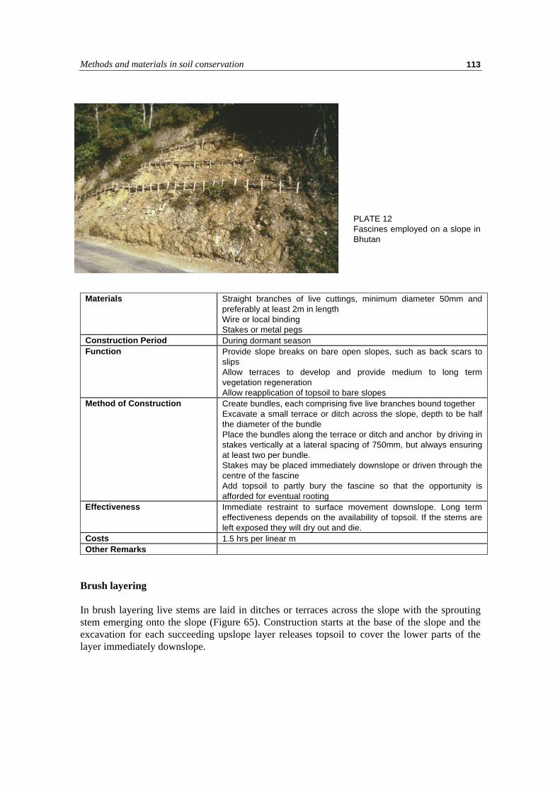
Methods and materials in soil conservation 113
PLATE 12Fascines employed on a slope inBhutan
Materials Straight branches of live cuttings, minimum diameter 50mm andpreferably at least 2m in lengthWire or local bindingStakes or metal pegs
Construction Period During dormant seasonFunction Provide slope breaks on bare open slopes, such as back scars to
slipsAllow terraces to develop and provide medium to long termvegetation regenerationAllow reapplication of topsoil to bare slopes
Method of Construction Create bundles, each comprising five live branches bound togetherExcavate a small terrace or ditch across the slope, depth to be halfthe diameter of the bundlePlace the bundles along the terrace or ditch and anchor by driving instakes vertically at a lateral spacing of 750mm, but always ensuringat least two per bundle.Stakes may be placed immediately downslope or driven through thecentre of the fascineAdd topsoil to partly bury the fascine so that the opportunity isafforded for eventual rooting
Effectiveness Immediate restraint to surface movement downslope. Long termeffectiveness depends on the availability of topsoil. If the stems areleft exposed they will dry out and die.
Costs 1.5 hrs per linear mOther Remarks
Brush layering
In brush layering live stems are laid in ditches or terraces across the slope with the sproutingstem emerging onto the slope (Figure 65). Construction starts at the base of the slope and theexcavation for each succeeding upslope layer releases topsoil to cover the lower parts of thelayer immediately downslope.

The use of vegetation in erosion control114
Materials Branches of rooting plants and treesConstruction Period During dormant seasonFunction Provides immediate surface stabilization to the depth of the layer
following the reinforced earth principleProvides deep stabilization after rooting
Method of Construction Start at the base of the slopeCreate a small terrace 500mm to 1m wide and at an angle of 10 - 30degrees into the slopePlace the branches at a rate of 20 per linear m. across the terracewith one quarter of the branch overhanging the slopeCreate a new terrace 500mm upslope using the excavated topsoil tofill in the terrace belowRepeat successively , moving up the slope
Effectiveness One of the most effective stabilization methodsCosts 1 - 2.5 hours per linear m.Other Remarks May be incorporated into new embankment construction
Methods and materials in soil conservation 115
References
Caterpillar Tractor Company. 1990. Caterpillar Performance Handbook. 21st edition. Peoria, Illinois.
Charles, J.A. and Perry, J. 1999. Rockfill. In: Stone: Building Stone, Rockfill and Armourstone inConstruction. M.R. Smith (ed.). Geological Society, Engineering Geology Special Publications 16,London.
Cooke, R.U. and Doornkamp, J.C. 1990. Geomorphology in Environmental Management: A NewIntroduction. 2nd Edition. Oxford University Press.
Coppin, N.J. and Richards, I.G. 1990. Use of Vegetation in Civil Engineering. Construction IndustryResearch and Information Association, London.
Crozier, M.J. 1986. Landslides: Causes, Consequences and Environment. Croom Helm, London.
Everett, D.H. 1961. The thermodynamics of frost damage to porous solids. Trans. Faraday Soc. 57,1541-51.
FAO. 1965. Soil erosion by water: some measures for its control on cultivated lands. FAO Land andWater Development Series 7. FAO, Rome.
FAO. 1960. Soil erosion by wind and measures for its control on agricultural lands. FAO Land andWater Development Series 6. FAO, Rome.
Fookes, P.G., Sweeney, M., Manby, C.N.D. and Martin, R.P. 1985. Geological and geotechnicalengineering aspects of low-cost roads in mountainous terrain. Engineering Geology 21: 1-152,Elsevier, Amsterdam.
Fookes, P.G. (ed.). 1997. Tropical Residual Soils. Geological Society Professional Handbook. TheGeological Society, London.
Fookes, P.G., Dearman, W.R. and Franklin, J.A. 1971. Engineering aspects of rock weathering. Quart. J.Eng. Geol. 4: 139-185.
Franklin, J.A., Brock, E. and Walton, G. 1971. Logging the mechanical character of rock. Trans. IMM,80: A1-A9.
Hansen, M.J. 1984. Strategies for classification of landslides. In: Slope Instability. Wiley, Chichester. pp1-25.
Hoek, E. and Bray, J.W. 1981. Rock Slope Engineering. Institution of Mining and Metallurgy, London.
Hudson, J.A. 1989. Rock Mechanics Principles in Engineering Practice. CIRIA. Butterworths, London.
ILO. 1986. Gabions. Training element and technical guide for SPWP workers. Booklet No 3.

References116
ILO. 1992. A participatory approach to environmental protection measures for hill irrigation schemes inNepal. Nepal SPWP Manual No. 1. ILO, Geneva.
Ingold, T.S. and Miller, K.S. 1988. Geotextiles Handbook. Thomas Telford, London
Jewell, R.A. 1996. Soil Reinforcement with Geotextiles. CIRIA Special Publication 123. ConstructionIndustry Research and Information Association, London.
Lawrance, C.J., Byard, R.J. and Beaven, P.J. 1993. Terrain Evaluation Manual. Transport ResearchLaboratory State of the Art Review 7. HMSO, London.
Legget, R.F. 1962. Geology and Engineering. 2nd edition. McGraw Hill.
MacGregor, F., Fell, R., Mostyn, G.R., Hocking, G. and McNally, G. 1994. The estimation of rockrippability. Quart. J. Eng. Geol. 27: 123-144.
Netterberg, F. 1971. Calcrete in road construction. CSIR Res. Rep. 286, Pretoria, CSIR.
Netterberg F. 1978 Calcrete wearing courses for unpaved roads. Civ. Eng. S. Afr., Vol 20 No 6, pp 129-138.
Peltier, L. 1950. The geographic cycle in periglacial regions as it is related to climatic geomorphology.Ann. Assoc. Amer. Geog. 49, 214-36.
Pettifer, G.S. and Fookes, P.G. 1994. A revision of the graphical method for assessing the excavatabilityof rock. Quart. J. Eng. Geol. 27: 145-164.
Schiechtl, H.M. and Stern, R. 1996 (English translation). Ground Bioengineering Techniques for SlopeProtection and Erosion Control. Blackwell Science, Oxford.
Schiechtl, H.M. and Stern, R. 1997 (English translation). Water Bioengineering Techniques forWatercourse Bank and Shoreline Protection. Blackwell Science, Oxford.
Stewart, G.A. and Perry, R.A. 1953. Survey of Townsville-Bowen Region (1950). Land Research Series,2. CSIRO 1120 (Australia).
Strakhov, N.M. 1967. The Principles of Lithogenesis. Vol. 1. Oliver and Boyd, Edinburgh.
Varnes, D.J. 1978. Slope movements and types and processes. In: Landslides: Analysis and Control,Spec. Rep. 176, Transp. Res. Board nat. Acad. Sci., Washington, pp 11-33.
Wang, H., Latham, J-P. and Poole, A. 1991. Predictions of block size distributions for quarrying. Quart.J Eng. Geol. 24: 91-99.