methodology to assess potential glint and glare hazards ... · methodology to assess potential...
TRANSCRIPT

Sandia is a multiprogram laboratory operated by Sandia Corporation, a Lockheed Martin Company, for the United States Department of Energy’s National Nuclear Security Administration under contract DE-AC04-94AL85000.
Methodology to Assess Potential Glint and Glare Hazards from Concentrating Solar Power Plants: Analytical Models and Experimental Validation
Clifford K. Ho, Cheryl M. Ghanbari, and Richard B. Diver
Concentrating Solar Technologies DepartmentConcentrating Solar Technologies Department Sandia National LaboratoriesSandia National Laboratories
Albuquerque, NM 87185Albuquerque, NM 87185 [email protected]@sandia.gov
ASME 2010 Energy Sustainability Conference
Phoenix, AZ, May 17 – 22, 2010
2
Overview
• Introduction
• Safety Metrics
• Glint and Glare Analysis
• Model Validation
• Summary

3
Introduction
• Glint and glare may cause unwanted visual impacts• Glint is momentary flash of light; glare is more continuous
source of excessive brightness• Visual impacts range from flash blindness to retinal burn
• Need quantified analysis of glint/glare to reduce uncertainties associated with visual impacts of CSP installations• Industry, military, government agencies (e.g., California
Energy Commission, Transportation Research Board)
4
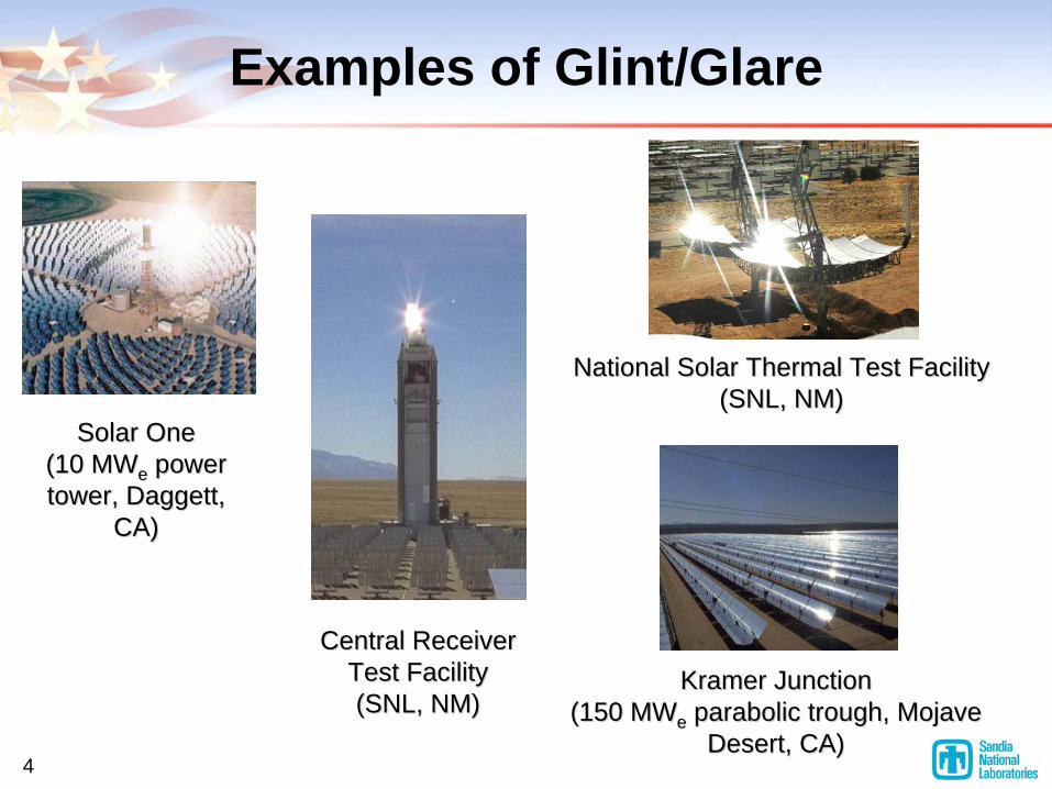
Examples of Glint/Glare
Solar OneSolar One (10 (10 MWMWee power power tower, Daggett, tower, Daggett,
CA)CA)
Central Receiver Central Receiver Test FacilityTest Facility (SNL, NM)(SNL, NM)
Kramer JunctionKramer Junction (150 (150 MWMWee parabolic trough, Mojave parabolic trough, Mojave
Desert, CA)Desert, CA)
National Solar Thermal Test FacilityNational Solar Thermal Test Facility (SNL, NM)(SNL, NM)
5
Overview
• Introduction
• Safety Metrics
• Glint and Glare Analysis
• Model Validation
• Summary
6
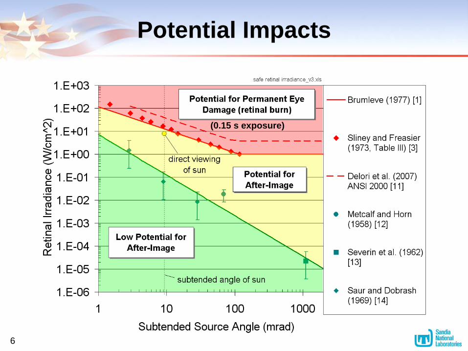
Potential Impacts
(0.15 s exposure)
7
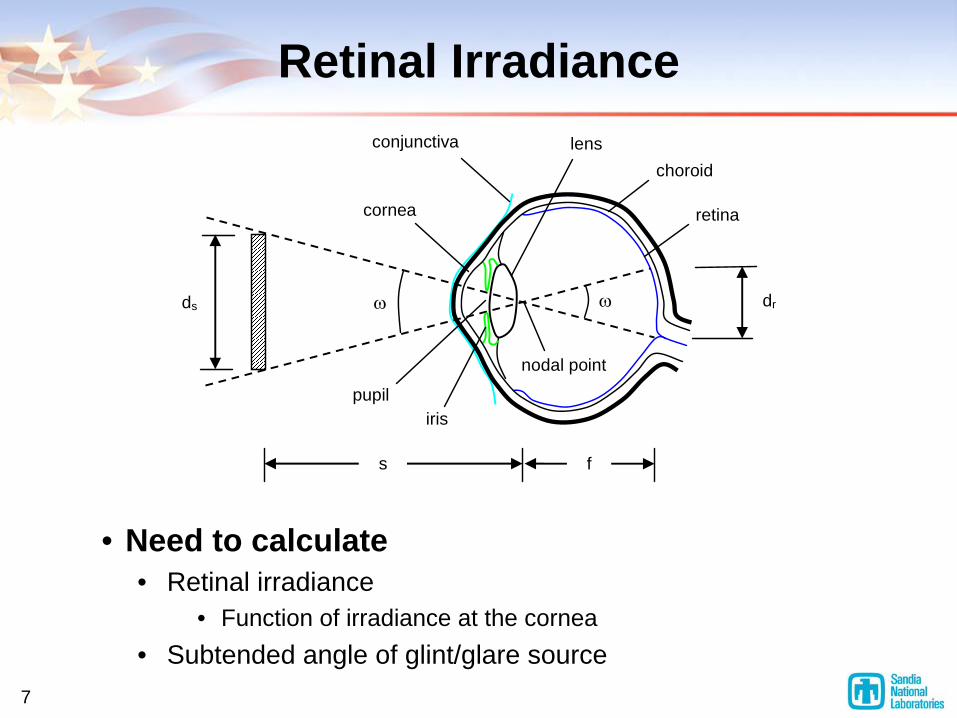
Retinal Irradiance
choroid
retina
lens conjunctiva
cornea
pupil iris
nodal point
f s
ds dr ω ω
• Need to calculate• Retinal irradiance
• Function of irradiance at the cornea• Subtended angle of glint/glare source
8
Overview
• Introduction
• Safety Metrics
• Glint and Glare Analysis
• Model Validation
• Summary

9
Modeling Approach
θ θ
Specular Reflection
Diffuse Reflection
• Analyze two different types of reflection
(polished surfaces; e.g., mirrors)
(rough surfaces; e.g., receivers)
10
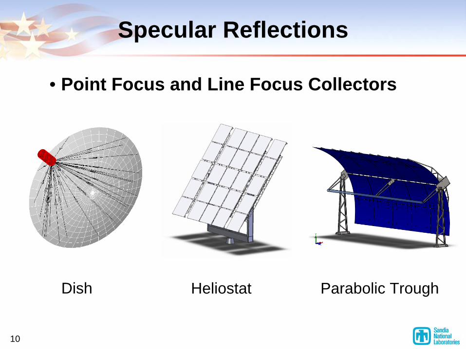
Specular Reflections
• Point Focus and Line Focus Collectors
Dish Heliostat Parabolic Trough
11
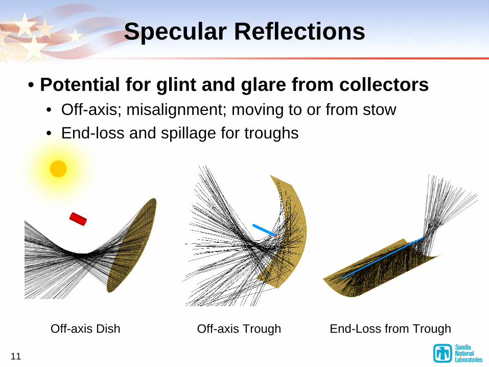
Off-axis Dish
Specular Reflections
• Potential for glint and glare from collectors• Off-axis; misalignment; moving to or from stow• End-loss and spillage for troughs
Off-axis Trough End-Loss from Trough
12
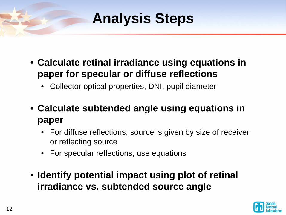
Analysis Steps
• Calculate retinal irradiance using equations in paper for specular or diffuse reflections• Collector optical properties, DNI, pupil diameter
• Calculate subtended angle using equations in paper• For diffuse reflections, source is given by size of receiver
or reflecting source• For specular reflections, use equations
• Identify potential impact using plot of retinal irradiance vs. subtended source angle
13
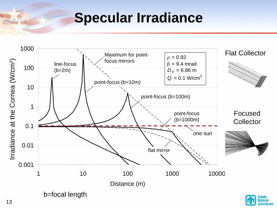
Specular Irradiance
0.001
0.01
0.1
1
10
100
1000
1 10 100 1000 10000Distance (m)
Maximum for point-focus mirrors
point-focus (b=100m)
ρ = 0.92β = 9.4 mradD h = 6.86 mQ = 0.1 W/cm2
point-focus (b=10m)
line-focus (b=2m)
point-focus (b=1000m)
flat mirror
b=focal length
one sun
Flat Collector
Focused Collector
Irrad
ianc
e at
the
Cor
nea
(W/c
m2 )
14
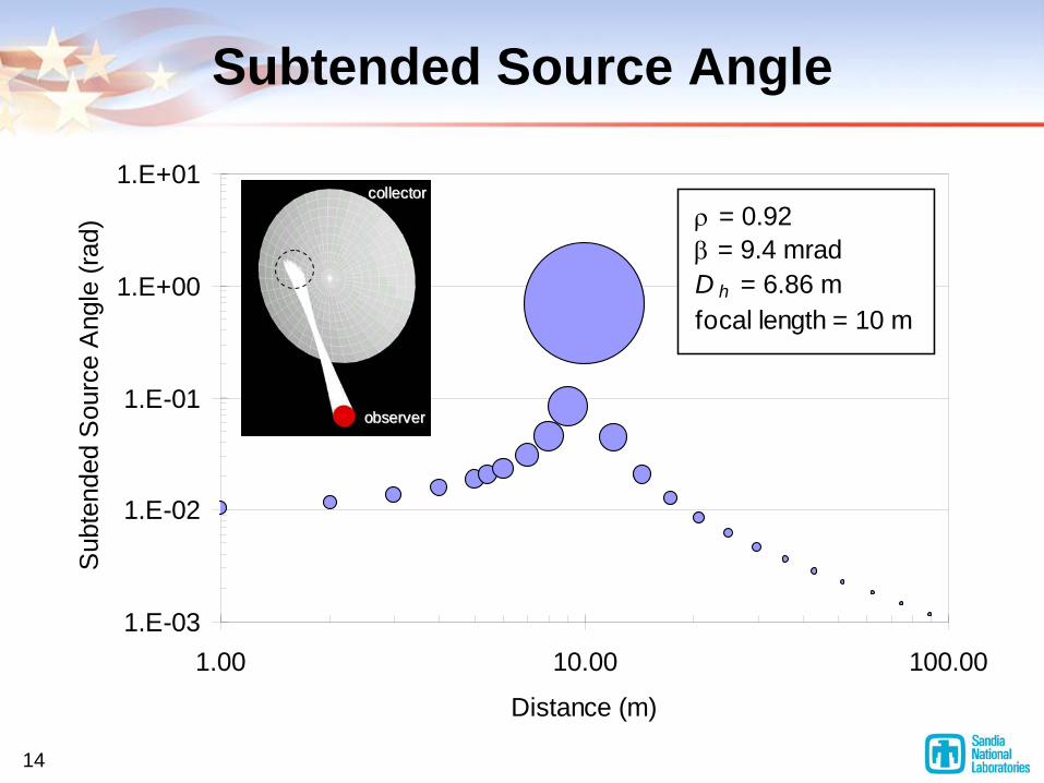
Subtended Source Angle
1.E-03
1.E-02
1.E-01
1.E+00
1.E+01
1.00 10.00 100.00
Distance (m)
Sub
tend
ed S
ourc
e A
ngle
(rad
) ρ = 0.92β = 9.4 mradD h = 6.86 mfocal length = 10 m
oobbsseerrvveerr
ccoolllleeccttoorr
15
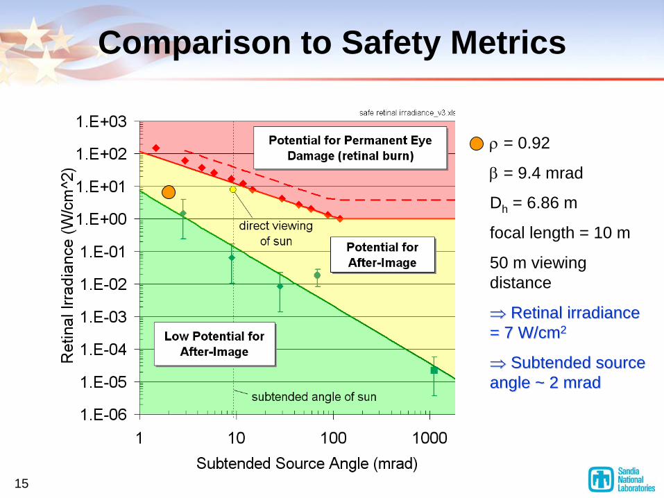
Comparison to Safety Metrics
ρ
= 0.92
β
= 9.4 mrad
Dh = 6.86 m
focal length = 10 m
50 m viewing distance
⇒⇒
Retinal irradiance Retinal irradiance = 7 W/cm= 7 W/cm22
⇒⇒
Subtended source Subtended source angle ~ 2 angle ~ 2 mradmrad

16
Overview
• Introduction
• Safety Metrics
• Glint and Glare Analysis
• Model Validation
• Summary
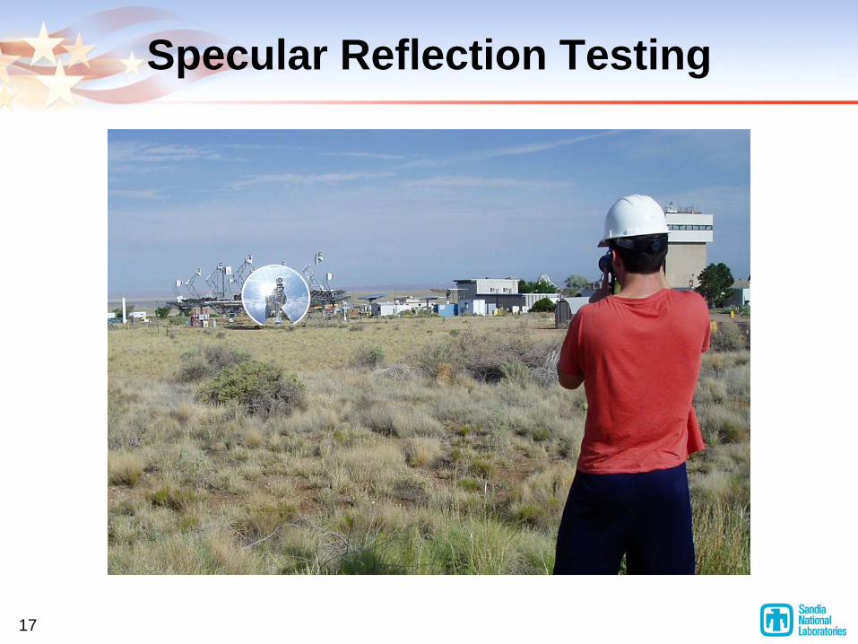
17
Specular Reflection Testing
18
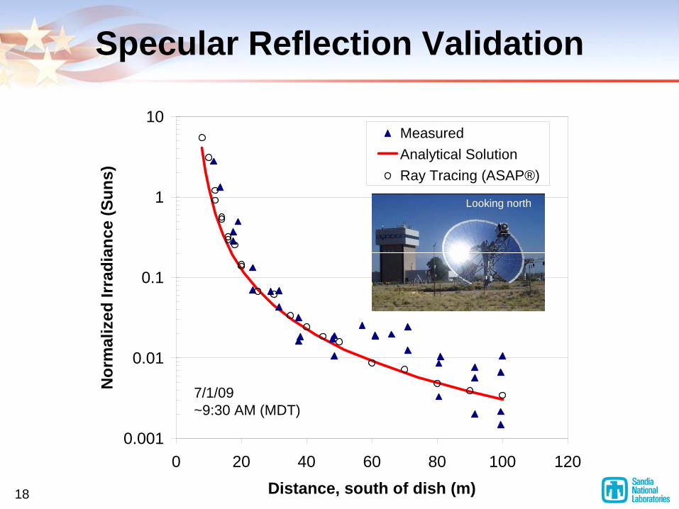
Specular Reflection Validation
0.001
0.01
0.1
1
10
0 20 40 60 80 100 120Distance, south of dish (m)
Nor
mal
ized
Irra
dian
ce (S
uns)
MeasuredAnalytical SolutionRay Tracing (ASAP®)
7/1/09~9:30 AM (MDT)
Looking north

19
Diffuse Reflection Testing

20
Diffuse Reflection Validation
0.00%
0.25%
0.50%
0.75%
1.00%
1.25%
1.50%
0 50 100 150 200 250Distance, north of tower (m)
Irrad
ianc
e (%
of o
ne s
un)
Measured
Analytical
7/2/09~10:00 AM (MDT)

21
Overview
• Introduction
• Safety Metrics
• Glint and Glare Analysis
• Model Validation
• Summary
22
Summary
• Glint and Glare can cause unwanted visual impacts
• Analytical models have been developed to quantify glint and glare• Specular reflections
• Point-focus and line-focus• Diffuse reflections
• Safety metrics have been compiled• Plot of retinal irradiance vs. subtended source angle can be
used to assess potential impact of quantified glint/glare
• Models have been validated with test data
23
Ongoing Work
• Reduce uncertainties associated with glint/glare for permitting and certification of solar power systems• Transportation Research Board
• Synthesis Report on “Investigating Safety Impacts of Energy Technologies on Airports and Aviation”
• California Energy Commission• Military• Industry
• Develop web-based tool for glint/glare analysis