methodology for controlling the ship’s path during the
TRANSCRIPT

28 Scientific Journal of Maritime Research 32 (2018) 28-35 © Faculty of Maritime Studies Rijeka, 2018
Multidisciplinary SCIENTIFIC JOURNAL OF
MARITIME RESEARCH
Multidisciplinarni znanstveni časopis
POMORSTVO
Methodology for Controlling the Ship’s Path during the Turn in Confined Waterways Srđan Vujičić1, Robert Mohović2, Ivica Đurđević Tomaš1
1 University of Dubrovnik, Maritime Department, Ćira Carića 4, 20000 Dubrovnik, Croatia, e-mail: [email protected]; [email protected] University of Rijeka, Faculty of Maritime Studies, Studentska 2, 51000 Rijeka, Croatia, e-mail: [email protected]
ARTICLE INFO
Preliminary communicationReceived 17 December 2017Accepted 17 May 2018
Key words:Manoeuvring Steering simulation Swept track Mariner’s practice Rate of the turn method
ABSTRACT
One of the basic tasks in the shipping industry is to ensure safe manoeuvring and navigation through channels and confined waterways. This paper has presented a practical and theoretical approach to the assessment of safe manoeuvring in waterways based on knowledge and experience. Experienced mariners had to sail through an approach to Thorn channel in a calm weather using their own knowledge and methods to determine variable angles of rudder deflection. The navigational performance has been determined in terms of deviation from the intended path. The results have indicated the difference in distances of the ship paths between all respondents as compared to the intended path. Besides determining the ship’s turn path, it is necessary to consider the factor F which represents the distance between the WOP and the beginning of the actual turn and the width of the swept track. However, the aim of this paper is to present a control methodology for mariners while working at sea.
1 Introduction
Safe navigation through canals and straits depends on the ship’s manoeuvrability, the features of the waterway, other external factors, and in particular the mariner’s sea-manship. One of the mariner’s basic tasks is a safe and suc-cessful manoeuvring, especially in confined waters. The required width of the waterway is estimated by various deterministic and probabilistic methods. It is often esti-mated by the quantitative method based on the probabil-ity model while using the results obtained from trials on the bridge simulator. The waterway was defined for this study: the approach channel to the Port of Southampton through the Thorn Channel where the grounding of con-tainer vessel P&O Nedlloyd Magellan occurred on 20th February 2001 due to an error of judgement during the execution of the turn.
The turn of the ship is a difficult manoeuvre for the mariner on account of determining the right timing of the wheel-over manoeuvre. Factors affecting the commence-ment of rudder deflection are the “wheel over point” (WOP) or “wheel over line” (WOL) that depend on the
ship’s manoeuvring performance, characteristics of the waterway, especially its depth and width, external natural factors such as wind speed, sea currents, and state of the sea. The control over the ship’s speed and rudder deflec-tion is at the mariner’s discretion. An incorrect, prema-ture or delayed reaction may, depending on the waterway, cause grounding, hitting the shore or navigational aids, or may cause the ship to heel due to the greater rudder deflection.
This paper has analysed the method of manoeuvring the ship in confined waters based on the research car-ried out on the bridge simulator. The research has been conducted on a sample of 10 respondents. The simulation has then been carried out by the authors who have used the elements, listed in this paper, important for control-ling the ship’s course. This has been the way to obtain the paths of the ship’s manoeuvre by each respondent. The analysis has shown various deviations from the intended path. These deviations occurred due to the respondents’ wrong assessment in terms of defining the WOP and the deflection angle. The knowledge of all the elements that affect the ship’s turn and of the exact radius of turn (ROT)

29S. Vujičić et al. / Scientific Journal of Maritime Research 32 (2018) 28-35
increases the safety of navigation and the control over the ship’s course with respect to the mariner’s discretion when giving the steering orders. The trial was conducted at the University of Dubrovnik on the Kongsberg’s Polaris bridge simulator approved by DNV (Det Norske Veritas).
Determining the width of the waterway in confined waters and predicting the ship’s manoeuvre are the basis for many research studies. The use of computer predic-tions provided by the “path predictor”, especially during the execution of the turn, according to Passenier P. O. [8], reduced the deviation from the given path by 70%. It is a mathematical model set by Van Breda and Passenier in 1998, but its implementation and reliability are still sub-ject to verification. The path prediction method may be based on hydrodynamic, mathematical, statistical, or ex-trapolation model. According to Hylten et al. [3], in 1970s, the Swedish and Danish pilots performed a turn based on the characteristics of a circle while taking into account WOP or WOL obtained trigonometrically. The trigonomet-ric functions were used to determine the surface of the ship’s path during the turn, depending on the ship’s pivot point.
According to Pietrzykowski et al. [9, 10, 2], mariners can use their knowledge to determine the width of the waterway (simulation method). The authors applied the Fuzzy method to ascertain the likelihood of a ship going aground.
2 Research Conducted on the Bridge Simulator and the Result Analysis
For this paper, the trial has been conducted at the University of Dubrovnik on the Kongsberg’s Polaris Ship Bridge Simulator approved by DNV Standard for Certification 2.14 for class A. These simulators have been developed to train and practice navigation and manoeu-vring on a modern bridge simulator, and to carry out dif-ferent types of research. Basically, the simulator consists of an instructor station, two full mission ship’s bridges, and various hydrodynamic ship models. Its key advantages are a realistic image with the visualisation of equipment and environment. Realistic visualisation, high fidelity hydrody-namic models, and ship manoeuvring features reduce the difference in reaction of trainees or respondents in simu-lation training as opposed to real life ship handling. High fidelity image has been achieved with the real-life infor-mation obtained from the ARPA radar and other devices.
The study included 10 Master Mariners, aged from 35 to 45, with over 10 years of seagoing service. Simulations have been carried out on a container ship (model CNTNR27L) with displacement D = 26995, length over all LOA = 181.8 m, beam B = 28 m, draught Ts = 9 m, propeller 142 rpm and maximum velocity vmax = 20 kn. A ship with a fixed pitch propeller has been chosen, being the typical propulsion for most of the world fleet. This type of propul-sion with the passive steering wheel is the most unfavour-able case in terms of ship’s manoeuvrability. A segment of
the waterway in the Thorn Channel off the Southampton coast has been selected for the analysis of navigation in confined waters. The segment selected has been the curved section of waterway where the marine incident oc-curred due to an error during the execution of the turn. In the predefined scenario, the ship was initially moving for-ward at the speed of 10 knots, but the respondents were allowed to change the speed when passing through the channel. The impact of currents and wind was not envis-aged in the scenario, visibility was good, and there was no traffic in the area.
The respondents were acquainted with the research task and the passage plan. Particulars of the ship were provided, along with the information obtained from the ARPA1 radar, ECDIS2 etc. Passage plan was displayed on the ECDIS screen and jointly analysed by the mariners. Each trial began with linear motion of the ship on a planned route at a distance of 10 LOA or 1 M from WOP. In this way, the respondents had enough time to learn more about the instruments and possible ambiguities and to agree on the execution of the turn.
According to the passage plan and their knowledge and experience, the respondents tried to follow the intended path and keep the course over ground. All respondents used the manual steering mode without changing the en-gine power. They used visualisation, ARPA and ECDIS, to track the ship movement. When turning the ship, they did not refer to the WOP or the radius of turn.
Each deviation from the intended path was analysed after trials. Figure 1 shows the intended and the actual path of each respondent’s vessel. Dotted red line indicates both the intended path according to the ECDIS passage plan and the circle radius of 0.48 M, while full lines in dif-ferent colours show each respondent’s path. The passage was planned for navigation in confined waters according to [4] and [7]. Particular paths can be compared and de-viations from the intended path and maximum deviations calculated by analysing Figure 1. This has led to the con-clusion that it was difficult for respondents to cope with the deviations from the set course in confined waters.
The selected segment of the channel has been divided into sectors A, B and C. After the ship movement simula-tion, the maximum deviation to port and starboard from the intended path has been calculated. Its quantitative val-ues are presented in Table1.
The table shows that the maximum deviation to port side is 0.20 M, and to starboard side is 0.08 M. The mini-mum deviation occurred in sector A where no major rudder deflection was necessary to keep the ship’s course. In sector B, the respondents had difficulties in dealing with the turn-ing path of the ship, so they deflected the rudder more (to starboard). In sector C, the respondents deflected the rud-der to port to annul the transverse shift of stern and to keep the desired course after the execution of the turn.
1 ARPA (Automatic Radar Plotting Aid)2 ECDIS (Electronic Chart Display and Information System)

30 S. Vujičić et al. / Scientific Journal of Maritime Research 32 (2018) 28-35
Figure 1 The Ship’s Intended and Respondents’ Path
Source: Authors
Table 1 Deviations from the intended path in nautical miles
Respondents SECTOR 1 2 3 4 5 6 7 8 9 10 Authors
APort 0.02 0.03 0.02 0.01 0.01 0.01 0.00 0.01 0.00 0.02 0.01Starboard
BPort 0.03 0.07 0.05 0.20 0.02 0.07 0.07Starboard 0.08 0.04 0.02
CPort 0.06 0.05 0.19 0.01 0.04 0.03 0.09 0.01Starboard 0.03 0.05 0.06
Source: Authors
31S. Vujičić et al. / Scientific Journal of Maritime Research 32 (2018) 28-35
3 The Analysis of the Theoretical Basis of a Ship Movement
This section briefly deals with the ship motion when performing the turn and with the factors affecting the ship manoeuvrability.
3.1 Ship Manoeuvrability
Ship manoeuvrability is one of its most important fea-tures and means the control over the ship motion when navigating and manoeuvring. Manoeuvring can be manual and partially or fully automated. The vessel traffic serv-ice which controls the traffic in confined waters has an important role in the process of manoeuvring. The abil-ity to keep the vessel’s course depends on the knowledge of the ship’s manoeuvrability and on the environment in which the navigation or manoeuvre is performed. The fol-lowing factors affect the process of manoeuvring the ship: manoeuvrability, characteristics of the waterway and the manoeuvring zone, the knowledge of meteorology and oceanography, and the human factor (both internal and external). Many factors affect the ship’s manoeuvrabil-ity such as structure and geometry of a ship, propulsion, steering, interference between the thruster and the rud-der. In order to define the required width of the waterway, in addition to the waterway characteristics and the ship’s technical and technological features, it is very important to take into account the seamanship of the mariner who manoeuvres the ship through a particular waterway.
3.2 The Ship’s Turn Theory
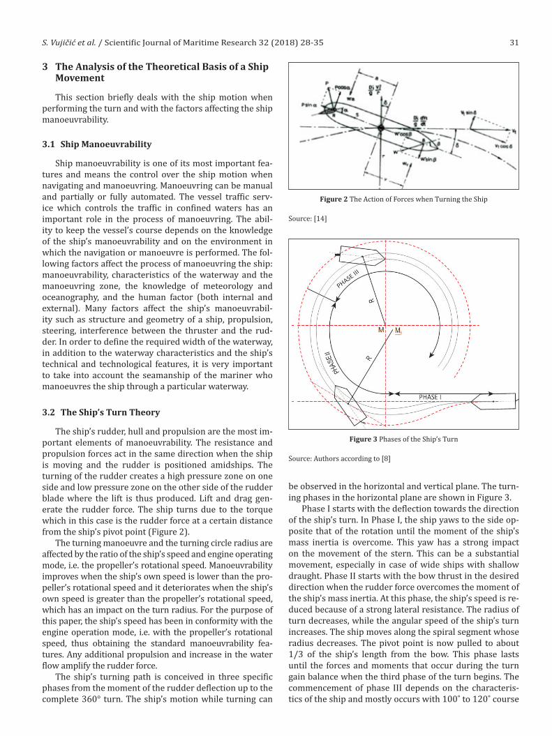
The ship’s rudder, hull and propulsion are the most im-portant elements of manoeuvrability. The resistance and propulsion forces act in the same direction when the ship is moving and the rudder is positioned amidships. The turning of the rudder creates a high pressure zone on one side and low pressure zone on the other side of the rudder blade where the lift is thus produced. Lift and drag gen-erate the rudder force. The ship turns due to the torque which in this case is the rudder force at a certain distance from the ship’s pivot point (Figure 2).
The turning manoeuvre and the turning circle radius are affected by the ratio of the ship’s speed and engine operating mode, i.e. the propeller’s rotational speed. Manoeuvrability improves when the ship’s own speed is lower than the pro-peller’s rotational speed and it deteriorates when the ship’s own speed is greater than the propeller’s rotational speed, which has an impact on the turn radius. For the purpose of this paper, the ship’s speed has been in conformity with the engine operation mode, i.e. with the propeller’s rotational speed, thus obtaining the standard manoeuvrability fea-tures. Any additional propulsion and increase in the water flow amplify the rudder force.
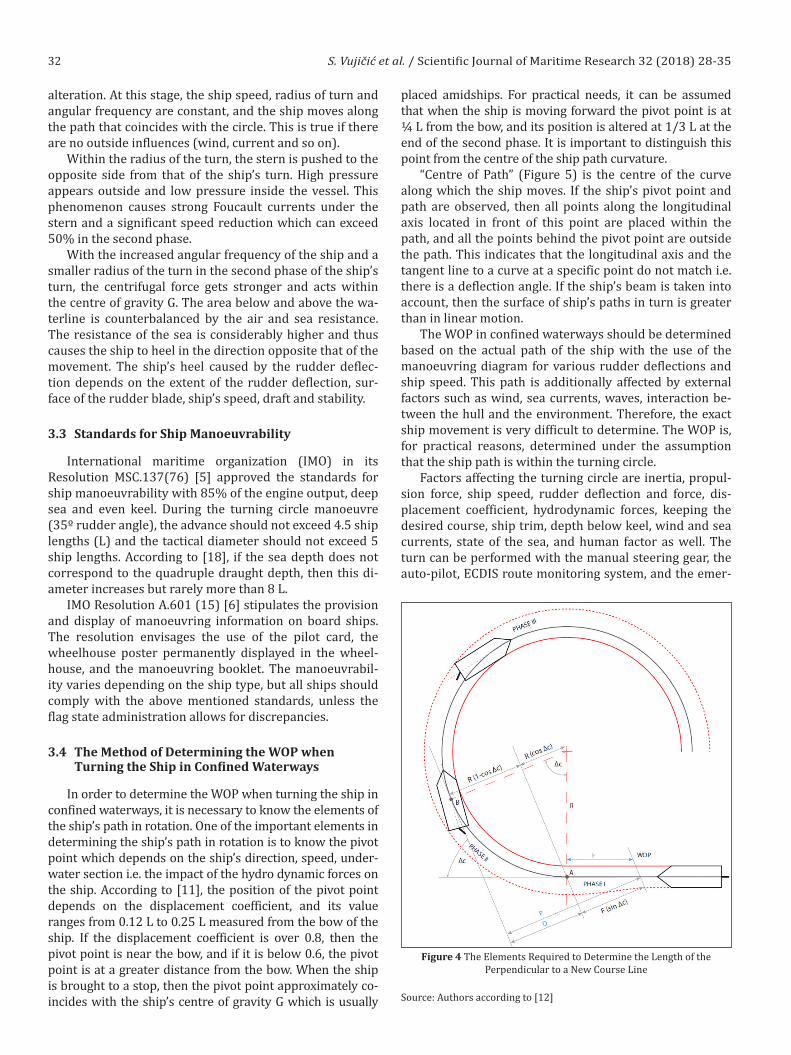
The ship’s turning path is conceived in three specific phases from the moment of the rudder deflection up to the complete 360° turn. The ship’s motion while turning can
be observed in the horizontal and vertical plane. The turn-ing phases in the horizontal plane are shown in Figure 3.
Phase I starts with the deflection towards the direction of the ship’s turn. In Phase I, the ship yaws to the side op-posite that of the rotation until the moment of the ship’s mass inertia is overcome. This yaw has a strong impact on the movement of the stern. This can be a substantial movement, especially in case of wide ships with shallow draught. Phase II starts with the bow thrust in the desired direction when the rudder force overcomes the moment of the ship’s mass inertia. At this phase, the ship’s speed is re-duced because of a strong lateral resistance. The radius of turn decreases, while the angular speed of the ship’s turn increases. The ship moves along the spiral segment whose radius decreases. The pivot point is now pulled to about 1/3 of the ship’s length from the bow. This phase lasts until the forces and moments that occur during the turn gain balance when the third phase of the turn begins. The commencement of phase III depends on the characteris-tics of the ship and mostly occurs with 100˚ to 120˚ course
Figure 2 The Action of Forces when Turning the Ship
Source: [14]
Figure 3 Phases of the Ship’s Turn
Source: Authors according to [8]
32 S. Vujičić et al. / Scientific Journal of Maritime Research 32 (2018) 28-35
alteration. At this stage, the ship speed, radius of turn and angular frequency are constant, and the ship moves along the path that coincides with the circle. This is true if there are no outside influences (wind, current and so on).
Within the radius of the turn, the stern is pushed to the opposite side from that of the ship’s turn. High pressure appears outside and low pressure inside the vessel. This phenomenon causes strong Foucault currents under the stern and a significant speed reduction which can exceed 50% in the second phase.
With the increased angular frequency of the ship and a smaller radius of the turn in the second phase of the ship’s turn, the centrifugal force gets stronger and acts within the centre of gravity G. The area below and above the wa-terline is counterbalanced by the air and sea resistance. The resistance of the sea is considerably higher and thus causes the ship to heel in the direction opposite that of the movement. The ship’s heel caused by the rudder deflec-tion depends on the extent of the rudder deflection, sur-face of the rudder blade, ship’s speed, draft and stability.
3.3 Standards for Ship Manoeuvrability
International maritime organization (IMO) in its Resolution MSC.137(76) [5] approved the standards for ship manoeuvrability with 85% of the engine output, deep sea and even keel. During the turning circle manoeuvre (35º rudder angle), the advance should not exceed 4.5 ship lengths (L) and the tactical diameter should not exceed 5 ship lengths. According to [18], if the sea depth does not correspond to the quadruple draught depth, then this di-ameter increases but rarely more than 8 L.
IMO Resolution A.601 (15) [6] stipulates the provision and display of manoeuvring information on board ships. The resolution envisages the use of the pilot card, the wheelhouse poster permanently displayed in the wheel-house, and the manoeuvring booklet. The manoeuvrabil-ity varies depending on the ship type, but all ships should comply with the above mentioned standards, unless the flag state administration allows for discrepancies.
3.4 The Method of Determining the WOP when Turning the Ship in Confined Waterways
In order to determine the WOP when turning the ship in confined waterways, it is necessary to know the elements of the ship’s path in rotation. One of the important elements in determining the ship’s path in rotation is to know the pivot point which depends on the ship’s direction, speed, under-water section i.e. the impact of the hydro dynamic forces on the ship. According to [11], the position of the pivot point depends on the displacement coefficient, and its value ranges from 0.12 L to 0.25 L measured from the bow of the ship. If the displacement coefficient is over 0.8, then the pivot point is near the bow, and if it is below 0.6, the pivot point is at a greater distance from the bow. When the ship is brought to a stop, then the pivot point approximately co-incides with the ship’s centre of gravity G which is usually
placed amidships. For practical needs, it can be assumed that when the ship is moving forward the pivot point is at ¼ L from the bow, and its position is altered at 1/3 L at the end of the second phase. It is important to distinguish this point from the centre of the ship path curvature.
“Centre of Path” (Figure 5) is the centre of the curve along which the ship moves. If the ship’s pivot point and path are observed, then all points along the longitudinal axis located in front of this point are placed within the path, and all the points behind the pivot point are outside the path. This indicates that the longitudinal axis and the tangent line to a curve at a specific point do not match i.e. there is a deflection angle. If the ship’s beam is taken into account, then the surface of ship’s paths in turn is greater than in linear motion.
The WOP in confined waterways should be determined based on the actual path of the ship with the use of the manoeuvring diagram for various rudder deflections and ship speed. This path is additionally affected by external factors such as wind, sea currents, waves, interaction be-tween the hull and the environment. Therefore, the exact ship movement is very difficult to determine. The WOP is, for practical reasons, determined under the assumption that the ship path is within the turning circle.
Factors affecting the turning circle are inertia, propul-sion force, ship speed, rudder deflection and force, dis-placement coefficient, hydrodynamic forces, keeping the desired course, ship trim, depth below keel, wind and sea currents, state of the sea, and human factor as well. The turn can be performed with the manual steering gear, the auto-pilot, ECDIS route monitoring system, and the emer-
Figure 4 The Elements Required to Determine the Length of the Perpendicular to a New Course Line
Source: Authors according to [12]

33S. Vujičić et al. / Scientific Journal of Maritime Research 32 (2018) 28-35
gency steering system. The manual steering with the set values of the rudder deflection and/or angular frequency of the turn and the autopilot which keeps the course or turns the ship in a new direction with the previously set values and parameters are commonly used in navigation.
According to the graph in Figure 4, F represents the distance between the WOP and the commencement of the actual turn which is 0.21 M or 2.1 LOA for the reference ship CNTNR27L. Soon after passing the point A, the ship turns at an angular frequency that should be brought to the desired value as soon as possible. Just before the ship reaches the desired course, it is necessary to reduce the angular frequency to 0. This requirement will be met with the rudder deflection to the opposite side of the turn.
The mathematical expression for the distance be-tween the perpendicular to the new course and the WOP is shown below and it depends on the differences between courses ∆c, the radius of circle R, and the distance between the WOP and the ship commencing its turn F.
D = R (1 – cos ∆c) (1)
P = D + (F × sin ∆c) (2)
Besides determining the ship’s turn path, to define the sufficient width of the waterway i.e. the maritime safety when turning the ship, it is necessary to consider the width of the ship’s turning path SB. This width can be de-termined by knowing the drift angle α, the length over all LOA and the beam B (Figure 5). The increasing width of the ship’s path in turn S is derived from the following sim-plified expression:
(S) = LOA × sin α (3)
The final width of the ship’s path in turn SB is obtained from the following expression:
(SB) = B + LOA × sin α (4)
It should be pointed out that the width of the navigable path has an impact on the allowed deviation in the rota-tion from the intended path.
4 Ship Tracking and Research Results
After the result analysis, the same simulation has been performed by the authors in such a way that, prior to the turn, the distance between the rudder deflection moment and the beginning of the actual turn has been determined, the distance F which best suited the reference vessel and the angular frequency have been determined. This ap-proach has provided a turn path similar to the intended path as shown in Figure 5.
The value of the distance F depends on the ship ma-noeuvrability i.e. on the initial ability to change the course of this particular ship. Some ships have these values de-fined for a specific deflection angle and a ship speed, but mariners are mostly not familiar with these values so they rely solely on their experience. In this study, by a multiple repetition of the turn according to the predefined scenario, the distance F and the initial rudder deflection angle have been defined for the ship speed of 10 knots. By analysing the ship motion produced by varied rudder deflections, it has been found that the distance F for the reference ship has been 0.21 M with gradual initial rudder deflections of up to15°.
The angular frequency of the turn depends on the ship’s speed in turn V (kn), radius of curve R (M), and the influ-ence of external factors. The following mathematical ex-pression is obtained from Figure [4] according to [1]:
= [˚/min] (5)
where represents the angular frequency in the turn,
while final value depends on the frequency (v) and
circle radius (R). The angular frequency is the ratio be-tween the sweep angle or the angle of yaw (Δc) and time (t) and it is denoted by ω.
For the purpose of this paper, a simplified scenario has been defined without external influences. That is why the angular frequency of turn ω (°/min.) can be determined with the expression:
[˚/min] (6)
According to the above expression for this specific case, the angular frequency of turn ω was 21°/min.
If the wind and sea currents are taken into account, than the expression according to Hilten and Wolkenfelt [11] can be applied.
The path presented in Figure 5 has been obtained from the predefined radius of turn R = 0.48 M, distance F = 0.21 M, ship’s speed V = 10 kn, gradual initial rudder deflections of up to15°, and with later changes in rudder deflection to
Figure 5 The Width of the Ship’s Path in Turn
Source: Authors according [12]

34 S. Vujičić et al. / Scientific Journal of Maritime Research 32 (2018) 28-35
keep the calculated angular speed of turn. On the defined WOP, the rudder has been gradually deflected to15°.
After the initiated turn, the rudder deflection has been controlled (reduced to 10°) in order to obtain the de-sired value of the angular frequency of the turn (ω 21°/min) which is monitored3 on the navigating bridge [13]. After achieving the desired angular frequency of the turn, the ship has started moving on the radius of the curve of 0.48 M. The ship has initiated the turn at the speed of 10 kn and has ended the turn at the speed of 9.2 kn. The en-gine output has not changed and the initial speed of 75 rpm has slightly decreased. The analysis of Figure 5 shows the minimum deviation from the path of the reference ship as compared to the intended path in phases I and III. The greatest deviation from the intended path is 0.01 (to
3 According to the SOLAS Regulation 19, Chapter V each ship over 50.000 GT must have a ROT indicator or any other device showing the change in the angular frequency in degrees per minute and the speed and distance measuring device.
starboard) which is the most favourable result compared to the results obtained in the research carried out on the sample of 10 respondents.
The research results have shown that a significantly smaller deviation in the turn from the intended path can be achieved when the following conditions are met: know-ing the ship manoeuvrability, well analysed navigation area, a thorough passage plan for confined waterways with the precisely determined radius of the turn, new course and WOP in relation to the distances D and F. The above mentioned method has provided the optimal con-trol of the ship’s turning path in confined waterways.
The research has shown that the respondents have not considered the necessary elements when defining the ship’s turn, and experience has shown that only few mari-ners take these facts into account in spite of the obligation to have a passage plan with precisely defined elements of the ship’s turn. Thus, the proposed model may be a means of precisely defining and executing the turn in confined waterways.
Figure 6 The Path of the Reference Ship Obtained by the Abovementioned Method in Relation to the Intended Path
Source: Authors

35S. Vujičić et al. / Scientific Journal of Maritime Research 32 (2018) 28-35
5 Conclusion
This research has discovered that mariners performed the ship’s turn in confined waters based on their rich ex-perience in the use of various rudder deflections and dif-ferent moments of deflection. In order to turn the ship with a minimum deviation from the planned path, it is necessary to take into account the turn-related theoreti-cal framework. The method for determining the rudder deflection moment with a minimum deviation from the planned path presented in this paper has been based on the radius of the path curvature and has defined the angu-lar frequency of the turn. This method has resulted in an acceptable deviation from the planned path. This research has shown that this method has obtained much better re-sults as compared to the execution of the turn based solely on the mariner’s experience. The research results could be used to determine the required minimum width of the curved segments of confined waterways where human fac-tor, i.e. the mariner’s detour from the intended path when performing the turn should be taken into account. In the future, unmanned ships will have to apply one of the turn models. Therefore, this model can be applied for that pur-pose. The testing has been performed on the bridge simu-lator on a sample of 10 respondents, so it would be good to have a larger sample size to obtain more reliable results. The impact of external factors, primarily of the surround-ing forces, should be considered in future researches.
References
[1] Đurđević T.I.: Geometric Display of Voyage Plan, “Naše More”, Volume 60, Issue 3-4, Oct 2013, pp. 49-54.
[2] Gucma L., Pietrzykowski Z.: Ship Manoeuvring in Restricted Areas: An Attempt to Quantity Dangerous Situations Using a Probalistic – Fuzzy Method, Journal of Navigation, Volume 59, 2006, pp. 251-262.
[3] Hilten M., Wolkenfelt P.: The Rate of Turn Required for Geo-graphically Fixed Turns: A Formula and Fast-Time Simula-tions, Journal of Navigation, Volume 53, Issue 01, Jan 2000, pp. 146-155.
[4] IMO RESOLUTION 893 (21) GUIDELINES FOR VOYAGE PLANNING, Feb 2000.
[5] IMO RESOLUTION MSC.137 (76): STANDARDS FOR SHIP MANOEUVRABILITY, adopted on 4 December 2002.
[6] IMO A.601 (15) PROVISION AND DISPLAY OF MANOEU-VRING INFORMATION ON BOARD SHIPS, Adopted on 19 November 1987.
[7] International Chamber of Shipping: Bridge Procedures Guide, Marisec publications, London 2007.
[8] Passenier, P.O. (1989): An Adaptive Track Predictor for Ships. Doctoral dissertation. University of Technology, Delft.
[9] Pietrzykowski Z.: Ship Manoeuvring in Restricted Areas: An Attempt to Quantify Dangerous Situations Using a Probalis-tic – Fuzzy Method, Journal of Navigation, Volume 59, 2006, pp. 251-262.
[10] Pietrzykowski Z.: Ship’s Fuzzy Domain – a Criterion for Nav-igational Safety in Narow Fairways, Journal of Navigation, Volume 61, 2008, pp. 499-514.
[11] Ship Handling Research and Training Centre: Manned Mod-el Ship Handling Course Ilawa, April 2005.
[12] Ship Handling Research, CSMART, the Center for Simulator Maritime Training, Almere, Netherlands 2015.
[13] SOLAS, Chapter V, Regulation 19 (2.9), “Carriage require-ments for ship-borne navigational systems and equipment”, Consolidated edition 2014.
[14] Definition “Kormilarenje”, Maritime encyclopedia, Volume 4, “Miroslav Krleža”, Zagreb, 1978, pp. 61-63.