method to design a hydro tesla turbine for...
TRANSCRIPT
1 Copyright © 2017 by ASME
Proceedings of the ASME 2017 Power and Energy Conference PowerEnergy2017
June 25-30, 2017, Charlotte, North Carolina, USA
PowerEnergy2017-3442
METHOD TO DESIGN A HYDRO TESLA TURBINE FOR SENSITIVITY TO VARYING LAMINAR REYNOLDS NUMBER MODULATED BY CHANGING WORKING FLUID
VISCOSITY
Mubarak S. Alrabie Mechanical & Manufacturing
Engineering Dept. Tennessee State University Nashville, Tennessee, USA
Faisal N. Altamimi Mechanical & Manufacturing
Engineering Dept. Tennessee State University Nashville, Tennessee, USA
Muhammad H. Altarrgemy Mechanical & Manufacturing
Engineering Dept. Tennessee State University Nashville, Tennessee, USA
Fatemeh Hadi Mechanical & Manufacturing
Engineering Dept. Tennessee State University Nashville, Tennessee, USA
Muhammad K. Akbar Mechanical & Manufacturing
Engineering Dept. Tennessee State University Nashville, Tennessee, USA
Matthew J. Traum Engineer Inc
Nashville, Tennessee, USA
ABSTRACT There has been a recent surge in interest for Tesla turbines
used in renewable energy applications such as power extraction
from low-quality steam generated from geothermal or
concentrated solar sources as well as unfiltered particle-laden
biomass combustion products. High interest in these bladeless
turbines motives renewed theoretical and experimental study.
Despite this renewed interest, no systematic Tesla turbine
design process based in foundational theory has been published
in the peer reviewed engineering literature. A design process is
thus presented which is flexible, allowing an engineering
designer to select and address goals beyond simply maximizing
turbine output power. This process is demonstrated by
designing a Tesla turbine where Reynolds number can be easily
varied while holding all other parameters fixed. Tesla turbines
are extremely sensitive to inter-disk spacing. It is therefore
desirable to design the experiment to avoid turbine
disassembly/reassembly between tests; this assures identical
disk spacing and other parameters for all tests. It is also
desirable to maintain similar working fluid mass flow rate
through the turbine in all tests to minimize influence of losses
at the nozzle impacting shaft power output differently across
experiments.
Variation in Reynolds number over more than two orders
of magnitude is achieved by creating a set of two-component
working fluid mixtures of water and corn syrup. Increasing
mixture mass fraction of corn syrup achieves increased working
fluid viscosity but only small increase in density with a
corresponding decrease in working fluid Reynolds number.
The overall design goal is to create a turbine that allows
modulating Reynolds number impact on Tesla turbine
performance to be evaluated experimentally. The secondary
goal is to size the turbine to maximize sensitivity to changes in
Reynolds number to make experimental measurement easier.
The presented example design process results in a Tesla
turbine with 8-cm-outer-diameter and 4-cm-inner-diameter
disks. The turbine will be able to access a range of Reynolds
numbers from 0.49 < Rem < 99.50. This range represents a
Reynolds number ratio of 𝑅𝑒𝑚,𝑚𝑎𝑥 𝑅𝑒𝑚,𝑚𝑖𝑛⁄ = 202.8, more
than two orders of magnitude and spanning the lower part of
the laminar range. The turbine’s expected power output will be
�̇� = 0.47 Watts with a delivered torque of 0.024 mN-m at a
rotation rate of ωmax = 1197 rev/min.
Combining the analytical equations underpinning the
design process with similarity arguments, it is shown that
shrinking the Tesla turbine’s physical scale drives the Reynolds
number toward 0. The resulting velocity difference between the
working fluid and the turbine disks gets driven toward infinity,
which makes momentum transfer and the resulting turbine
efficiency extremely high. In other words, unlike conventional
turbines whose efficiency drops as they are scaled down, the

2 Copyright © 2017 by ASME
performance of Tesla turbines will increase as they are made
smaller.
Finally, it is shown through similarity scaling arguments
that the 8-cm-diameter turbine resulting from the design
process of this paper and running liquid Ethylene Glycol
working fluid can be used to evaluate and approximate the
performance of a 3-mm-diameter Tesla turbine powered by
products of combustion in air.
INTRODUCTION Tesla turbines (also called boundary layer turbines, disk
turbines, or drag turbines) operate through a mechanism
different from conventional axial turbines. In a conventional
turbine, working fluid impinges upon aerodynamic blades to
generate rotational force through aerodynamic momentum
transfer. By contrast, Tesla turbines generate rotational force via
momentum transfer through shear stresses as working fluid
spirals through micro-channels created by flat, parallel, co-
rotating disks. As a result, Tesla turbines have been observed to
be robust against two-phase flow [1], a mixture of phases that
typically cannot be introduced into conventional axial or radial
turbines without ablating and damaging the aerodynamic blades
[2-5]. Resulting Tesla turbine renewable energy applications
include power extraction from particulate-laden wood gas as
well as from low-quality two-phase flow obtained from
concentrated solar, industrial heat recovery, or geothermal heat
sources – applications all unsuited for conventional turbines.
Several Tesla turbine parameters are thought to (or have
been shown to) impact performance, including disk spacing;
disk number; disk surface roughness; number, size, and shape
of nozzles; location/orientation of nozzles and exhaust ports;
and working fluid thermodynamic and physical properties [6,
7]. However, little theoretical or experimental exploration of
these parameters has occurred because Tesla turbines remain
generally outside mainstream hydro-, gas-, and stream-turbine
research. Thus, there is no generally accepted design or sizing
methodology in the literature for Tesla turbines that considers
these parameters. Further fueling estrangement of this
important technology from mainstream research, the knowledge
and capability gap for Tesla turbine design has been filled by
the empirical guidelines of amateur hobbyists and not verified
or understood using systematic engineering analysis [8, 9.]
To address the need for Tesla turbine design and sizing
methodologies in the peer reviewed engineering literature, the
goals of this paper are to 1) utilize what established Tesla
turbine performance theory does exists to develop the needed
methodology; 2) select a particular design goal different from
the conventional desired turbine design outcome, maximized
power output; and 3) apply the methodology to extract key
physical and geometric turbine parameters that will be used for
turbine construction and testing in a later work.
The primary design goal is to create a Tesla turbine where
a single identified parameter can be easily varied to test its
performance impact on the turbine while holding all other
parameters fixed. A secondary goal is to size the turbine to
maximize sensitivity to the selected variable parameter making
experimental measurement easier once the turbine is built.
To facilitate design, a predictive closed-form analytical
solution for Tesla turbine rotation rate and efficiency was found
in the literature [10-12] and extended into a systematic design
technique that includes power output, torque, and sensitivity to
variable parameters [13]. This theoretical work is applied here
to the design of an experimental Tesla turbine to demonstrate
the methodology and extract interesting results for discussion.
To achieve the primary design goal, the turbine will be
configured so that one important parameter can be varied while
the rest are held fixed. Looking forward, this approach will be
used in future work to isolate and verify experimentally the
turbine performance impacts of various parameters thought to
be important but never systematically verified: disk spacing;
disk number; disk surface roughness; number, size, and shape
of nozzles; location / orientation of nozzles and exhaust ports;
working fluid thermodynamic and physical properties; etc. So,
which variable does an experimenter choose to modulate first?
One experimental series considered was increasing the
number of turbine disks between runs to observe impact on
power output. However, Tesla turbine power output is thought
to be extremely sensitive to geometric variables. To add disks
between runs would require turbine disassembly and
reassembly between tests with no guarantee of identical fitment
(especially disk spacing) between runs. So, an experimental
series with increasing disk number would degrade into a
precision engineering fitment problem. Instead, for a first
experimental test it is desirable to vary a parameter that avoids
turbine disassembly/reassembly between tests. Along similar
lines, it is thought that Tesla turbine performance is sensitive to
loss mechanisms at the nozzle. It is therefore desirable to
maintain similar working fluid mass flow rate through the
turbine in all tests to minimize variable nozzle losses across
experiments.
This set of constraints makes undesirable the possibility of
making geometric changes to the turbine as well as varying
working fluid flow rate through it between experiments. As a
result, the remaining parameter that can be varied is Reynolds
number. It is known that power output of conventional small
aero-derived turbines operating in the laminar range is highly
sensitive to Reynolds number [14-16]. By contrast, if Tesla
turbines were insensitive to Reynolds number variation, they
could become a more sought after technology for power
extraction scenarios where the viscosity or density (and hence
Reynolds number) of working fluid changes intermittently,
unpredictably, and/or uncontrollably during operation; for
example, in a terrestrial solar-fired power cycle or in space-
based applications where the system is rapidly cycling between
solar exposure and shade [17].
With varying Reynolds number identified as the primary
design objective, the secondary goal is to maximize the
sensitivity of Tesla turbine output shaft power to changes in
Reynolds number to facilitate easy experimental measurement.
High sensitivity is achieved by taking derivatives of the turbine

3 Copyright © 2017 by ASME
model analytical power function with respect to variable
parameters and finding extrema.
BACKGROUND & THEORY The Tesla turbine was patented in 1913 [18]. Attempts
exist in the hobby literature to develop closed-form analytical
solutions relating geometric and working fluid parameters to
Tesla turbine performance [8, 9]. Swithenbank also contributes
prolifically to the hobby literature [19]. The isolated academic
work of Rice and colleagues [20-24] and experiments of some
others [25-34] contribute to understanding of Tesla turbine
performance. A few review articles, which focus on measuring
and maximizing power output, have also been published [6,
35]. This Spartan reference set constitutes the bulk of published
peer reviewed Tesla turbine literature, which pales in
comparison by volume and detail to the available body of work
on conventional axial turbines.
A resurgent interest in Telsa turbines for their ability to
process two-phase and particulate laden working fluid
characteristic of renewable energy systems has sparked a
number of recent theoretical studies and computational fluid
dynamic (CFD) modeling [36-39]. While other candidate
closed-form analytical models do exist [40], the 2010
publication by Carey [10] represents the most satisfactory
baseline differentiable closed-form analytical model relating
geometric and working fluid parameters to Tesla turbine
performance.
This approach begins with the Navier-Stokes equations in
cylindrical coordinates applied to working fluid interaction with
the rotating disk of a Tesla turbine. It results in the following
form for �̂�(𝜉, 𝑅𝑒𝑚∗ ), the dimensionless tangential velocity
difference between the disk rotor and working fluid inside the
turbine at any radial location,
�̂�(𝜉, 𝑅𝑒𝑚∗ ) =
𝑒
24𝜉2
𝑅𝑒𝑚∗
𝜉[
𝑅𝑒𝑚∗
24𝑒
−24𝜉2
𝑅𝑒𝑚∗
+ �̂�𝑜 −𝑅𝑒𝑚
∗
24𝑒
−24
𝑅𝑒𝑚∗
] (1)
where ξ = r/ro is a dimensionless radial disk location; Ŵo is the
dimensionless relative disk/fluid velocity at the disk outer
radius (ξ = 1); and 𝑅𝑒𝑚∗ is a modified Reynolds number:
𝑅𝑒𝑚∗ =
2𝑏�̇�𝑐
𝜋𝜇𝑟𝑜2 (2)
In addition, the turbine’s efficiency (dimensionless power) is
given as
𝜂 = 1 −(�̂�𝑖+𝜉𝑖)𝜉𝑖
(�̂�𝑜+1) (3)
where Ŵi is the dimensionless relative disk/fluid velocity at the
exhaust ports at the disk inner radius. This baseline model was
modified, as described elsewhere [13], to include expressions
for torque,
Γ =�̇�
𝜔 (4)
power output,
�̇� = �̇�(𝑣𝜃,𝑜𝑈𝑜 − 𝑣𝜃,𝑖𝑈𝑖) (5)
and sensitivity of efficiency (dimensionless power) to variable
parameters, including Reynolds number and dimensionless disk
size,
𝜕𝜂
𝜕𝑅𝑒𝑚∗ =
−1
�̂�𝑜+1{
1
24− [
24
𝑅𝑒𝑚∗ 2 (�̂�𝑜 −
𝑅𝑒𝑚∗
24) (𝜉2 − 1) +
1
24] 𝑒
24(𝜉2−1)
𝑅𝑒𝑚∗
} (6)
𝜕𝜂
𝜕𝜉= −
𝜉
�̂�𝑜+1[
48
𝑅𝑒𝑚∗ (�̂�𝑜 −
𝑅𝑒𝑚∗
24) 𝑒
24(𝜉2−1)
𝑅𝑒𝑚∗ + 2] (7)
DESIGN PROCESS The goal of any successful engineering design process is
the communication of the fully specified system to the person
responsible for building it [41]. Additionally, for an
experimental turbine with one variable parameter, the design
process must result in a system capable of producing enough
power to be easily measured while maximizing power output
sensitivity with respect to the variable parameter.
To design this Tesla turbine, all variables that could be
Customer Need →
Variable Parameter↓
Working Fluid
Compatibility
Parameter
Change Ease
Flat Disk
Compatibility
Accommodates
> 3 Disks
Disk Spacing
Maintained
Experiment
Size
Weighted
Total
Need Importance Weight 1 5 5 3 2 3
Inlet Diameter 3 3 5 4 2 1 62
Outlet Diameter 3 3 5 4 2 1 62
Disk Spacing 4 2 4 4 5 1 59
Disk Number 5 2 3 5 4 3 62
Fluid Viscosity & Density 5 5 5 4 5 5 92
Mass Flow Rate 4 5 4 4 5 4 83
Nozzle Location 3 4 2 2 1 1 44
Nozzle Number 2 5 2 3 1 2 54
Table 1: Pugh Chart quantitative down-selection process to viscosity and density as selected variable turbine parameters.

4 Copyright © 2017 by ASME
modulated were identified with emphasis on physical and
working fluid parameters thought to strongly influence
performance. A Pugh Chart, Table 1, was populated with these
parameters and engineering down-selection performed to
identify the parameter best meeting experimental criteria
outlined.
The conclusion emerging from this analysis was that
working fluid viscosity and density together (kinematic
viscosity) is the preferred parameter to vary to best meet design
requirements. In the analytical model of Eq. (1), the only
dimensionless variable directly influenced by viscosity and
density with all other parameters fixed is 𝑅𝑒𝑚∗ . Therefore, the
most universal way to designate varying only working fluid
density and viscosity together is to describe varying Reynolds
number.
To complete the design, all other unspecified turbine
parameters needed to be set based on analytical model
calculations: ndisks, ro, ri, t, b, h, Ẇ, and ṁ. The first six are
physical turbine parameters, the seventh is the needed turbine
power output, and the final parameter is working fluid mass
flow rate, which is set by the pump driving fluid through the
turbine and fluid return loop. Externally-influenced parameters,
Ẇ and ṁ, were set first, and the analytical model was then used
to set the physical turbine parameters to maximize turbine
power sensitivity to variable kinematic viscosity.
Output Power Selection
The first parameter set was target turbine power output. A
small 0.5-watt brushed DC motor will be connected to the
turbine and run as a generator to provide load and produce
electrical power. This power will be measured as Reynolds
number is varied to determine its influence. Tesla turbines
produce power at high shaft rotation rate and low torque. So,
0.5 watts was selected because it is a power large enough to be
easily measureable, but it does not require a motor so large as
to prevent the Tesla turbine from spinning up.
The selected motor is a Maxon A-max 12 precious metal
brushed 0.5-Watt 3.0 V DC motor designed to spin at 13700
rpm at no load with a maximum torque of 0.872 mN-m in
motor mode.
Working Fluid Selection
Variation in working fluid Reynolds number of over 200
times (and encompassing the lower end of the laminar flow
range) with no change in mass flow rate is achieved by creating
a series of two-component mixtures of two perfectly miscible
fluids with dramatically different viscosities. Notably, Reynolds
number could also have been affected by picking a viscous
fluid and increasing its temperature between runs as was done
via CFD modeling by Hasan and Benzamia [42]. However
increasing working fluid temperature would also have
measurably increased energy availability at the turbine inlet
between runs making energy extraction comparisons more
challenging. So, modulating viscosity through mixing was
selected as the preferred approach. Due to its availability and
ease of use, water was selected as one of the two candidate
liquids.
The second liquid must therefore be totally miscible in
water and have a significantly higher viscosity. Increasing
mixture mass fraction of this second fluid achieves increased
working fluid viscosity with only small increase in density. A
corresponding decrease in working fluid Reynolds number
results. Table 2 shows the candidate fluids considered along
with their key measured properties. As reliable literature values
for many of these fluids’ properties were difficult to find,
viscosity and density were directly measured at room
temperature (~ 24 °C). Viscosity was measured using a Keyu
NDJ-8S Digital Rotary Viscometer, and density was measured
by filling a 10 mL graduated cylinder and weighing on an
Ohaus Scout Pro digital balance.
For modeling purposes, binary mixture viscosity was
estimated via the Refutas equation technique [43]. Using the
kinematic viscosity (in centistokes) at the mixture temperature,
the viscosity blending number (VBN) of each component is
calculated,
𝑉𝐵𝑁𝑖 = 14.534 × 𝑙𝑛[𝑙𝑛(𝜈𝑖 + 0.8)] + 10.975 (8)
The mixture VBN is then calculated via multiplication by
mixture component mass fraction,
𝑉𝐵𝑁𝑚𝑖𝑥𝑡𝑢𝑟𝑒 = (𝑥𝐴 × 𝑉𝐵𝑁𝐴) + (𝑥𝐵 × 𝑉𝐵𝑁𝐵) (9)
Finally, the kinematic viscosity of the mixture is extracted
by inverting the VBN algorithm.
𝜈𝑚𝑖𝑥𝑡𝑢𝑟𝑒 = 𝑒𝑥𝑝 [𝑒𝑥𝑝 (𝑉𝐵𝑁𝑚𝑖𝑥𝑡𝑢𝑟𝑒−10.975
14.534)] − 0.8 (10)
Table 2: Measured viscosity and density of candidate fluids
added in a binary mixture with water to facilitate Reynolds
number modulation of Tesla turbine working fluid.
Measured
Parameters
Temperature
[°C]
Viscosity
[kg m-1
s-1
]
Density
[kg m-3
]
Water 24 0.0010 1007
Ethylene
Glycol 24 0.0019 1095
Propylene
Glycol 24 0.0036 1022
Fructose Syrup
(Maple Syrup) 24 0.953 1356
Glucose Syrup
[Corn Syrup] 24 4.400 1383
Sucrose Syrup
[Molasses] 24 6.919 1458

5 Copyright © 2017 by ASME
Based on its relatively high viscosity, economical
commercial availability in large batches, experimentally-
measured physical property batch-to-batch consistency, and
availability of references to estimate and model its viscosity
[44], Glucose syrup (corn syrup) was selected as the second
components in the variable viscosity binary mixture.
During future turbine experiments, working fluid mixture
properties will be measured quickly and accurately right before
tests using the Keyu NDJ-8S Digital Rotary Viscometer. These
well-characterized mixtures will then then be pumped through
the Tesla turbine at a predetermined mass flow rate, which is set
by power input to the pump. At the end of each experiment,
fluid properties will again be measured to account for any drift
arising from temperature change, mixture component
evaporation, and/or chemical changes in the mixture.
Pump Selection and Mass Flow Determination
The mass flow rate parameter, �̇�, is set by selection of a
pump. To maintain constant �̇� across various experimental runs
despite changing working fluid viscosity, power delivered to
the pump must be reduced as the mixture mass fraction of water
increases. To achieve this level of control, a variable DC power
supply is used to drive the pump with input power reduced at
lower working fluid viscosities.
Use of a fluid mixture instead of pure water suggested need
to use a diaphragm pump to provide continuous flow while
avoiding possible fouling or damage to internal components of
a conventional rotary pump. The selected pump must provide
adequate mass flow rate to access most of the laminar range
considering Reynolds number for flow between circular flat
plates [45],
0 < 𝑅𝑒𝑚 =�̇�𝑐
𝜋𝑟𝑜𝜇< 2000 (11)
To reach the upper laminar flow regime range, the working
fluid mixture with lowest fluid viscosity (100% water) is used.
The selected pump is a Seaflo 24.5-amp 12 VDC 53-Series
diaphragm pump with nameplate capability to deliver 7.0
gallons-per-minute (26.5 liters-per-minutes) at 60 PSI (413.7
kPa).
As described above, it is desirable to maintain constant �̇�
as working fluid viscosity is varied across multiple
experimental runs. To establish the fixed �̇� used in repeat
experiment, the available pump mass flow rate as a function of
fluid viscosity is determined gravimetrically by running fluid of
increasing viscosity through the pump and weighing
accumulation as a function of time. These data are then used to
fit a predictive power function for the pump’s performance that
relates viscosity to maximum flow rate.
Since the purpose of this experiment is to explore the
largest range of laminar Reynolds numbers, it is desirable to
maximize the ratio 𝑅𝑒𝑚,𝑚𝑎𝑥 𝑅𝑒𝑚,𝑚𝑖𝑛⁄ where 𝑅𝑒𝑚,𝑚𝑎𝑥 is the
Reynolds number for pure water at the mass flow rate fixed for
the experiment, and 𝑅𝑒𝑚,𝑚𝑖𝑛 is the Reynolds number for the
water/corn syrup mixture used to fix �̇�. The range of available
Reynolds numbers for the fluid mixture is bound by the range
of mixture viscosities: 0.001 𝑘𝑔
𝑚−𝑠 (water) < 𝜇 < 4.4
𝑘𝑔
𝑚−𝑠 (corn
syrup).
It is recognized that the Reynolds number of Eq. (11)
includes the outer disk radius, 𝑟𝑂, in the denominator. Rem can
be made arbitrarily large by making 𝑟𝑂 smaller. However, there
is a practical limit on the smallness of 𝑟𝑂, which is discussed in
the next sub-section “Selection of Outer and Inner Disk Radii”.
Since for both 𝑅𝑒𝑚,𝑚𝑎𝑥 and 𝑅𝑒𝑚,𝑚𝑎𝑥 the parameters �̇�𝑐 and 𝑟𝑂
are the same, the ratio simplifies to a viscosity quotient,
𝑅𝑒𝑚,𝑚𝑎𝑥
𝑅𝑒𝑚,𝑚𝑖𝑛=
(�̇�𝑐
𝜋𝑟𝑜𝜇)
𝑚𝑎𝑥
(�̇�𝑐
𝜋𝑟𝑜𝜇)
𝑚𝑖𝑛
=𝜇𝑚𝑎𝑥
𝜇𝑚𝑖𝑛 (12)
The largest possible 𝑅𝑒𝑚,𝑚𝑎𝑥 𝑅𝑒𝑚,𝑚𝑖𝑛⁄ ratio within the
constraints on �̇� and 𝜇 is determined by iteration. For the
selected pump and binary fluid components the mass flow rate
range is 0.0168 𝑘𝑔
𝑚−𝑠 < 𝑚 ̇ < 0.025
𝑘𝑔
𝑚−𝑠 which yields a Reynolds
number ratio range of 202.8 < 𝑅𝑒𝑚,𝑚𝑎𝑥 𝑅𝑒𝑚,𝑚𝑖𝑛⁄ < 392.5.
While it is desirable to maximize 𝑅𝑒𝑚,𝑚𝑎𝑥 𝑅𝑒𝑚,𝑚𝑖𝑛⁄ ,
access to the largest experimental space, it is also important to
note two more factors: 1) where along the 𝜕𝜂 𝜕𝑅𝑒𝑚⁄ curve
[Fig. 1] the selected design point falls and 2) what power is
being produced by the turbine at this design point.
In the range 200 < 𝑅𝑒𝑚 < 800, |𝜕𝜂 𝜕𝑅𝑒𝑚⁄ | is largest,
which means the experiment is most sensitive to Reynolds
number variations in this region: a desirable operational range
when considered in isolation from the rest of the problem.
However, large ⌈𝜕𝜂 𝜕𝑅𝑒𝑚⁄ ⌉ only occurs for large ξ, which
corresponds to turbine power output well below the established
0.5-Watt set point. Low power output is undesirable because
the relative uncertainty is this measurement is fixed, making a
small signal hard to discern from the noise.
Figure 1: The derivative of turbine efficiency (dimensionless
power) with respect to 𝑅𝑒𝑚⬚ plotted for 0.1 = ξ and 0.4 < ξ <
0.9 at 0.1 increments shows the derivative magnitude to be
largest at ξ = 0.9 and 𝑅𝑒𝑚 ≈ 200. This locus of maximized
sensitivity corresponds to low turbine power output and is not a
practical design point.
6 Copyright © 2017 by ASME
Selection of Outer and Inner Disk Radii
The Tesla turbine performance embodied in Eq. (1) and Eq.
(3) depends only on the dimensionless parameters 𝑅𝑒𝑚∗ and
𝜉 = 𝑟/𝑟𝑂. Therefore, the disk’s outer and inner diameters can
be set with some degree of flexibility subject to four
constraints. First, 𝑟𝑂 cannot be so small as to violate the
restriction of Eq. (11) and cause 𝑅𝑒𝑚 > 2000, which would
trip fluid to turbulence. While there is nothing physically
preventing the flow from being turbulent, Eq. (1) upon which
this entire analysis is predicated assumes laminar flow
momentum transfer between the working fluid and disk. Thus,
violating the laminar assumption invalidates this whole
analysis. Considering other parameters already set, 𝑟𝑂 > 0.002
m to keep the flow laminar. Second, small 𝑟𝑂 necessitates high
rotation rate to achieve power output at the 0.5 Watt range
specified. If making 𝑟𝑂 small, appropriate bearings must be
found to support shaft rotation rates in excess of 25,000 rpm.
Third, 𝜉𝑖 = 𝑟𝑖/𝑟𝑂 must be in a range that promotes strong
turbine power sensitivity to Reynolds number (see Fig. 2) and
high overall power output. As described elsewhere [13], these
design needs are diametrically opposed. Thus, a compromise is
struck by setting 𝜉𝑖 = 0.5 to provide adequate power and
sensitivity. Fourth, the inner diameter must be large enough to
accommodate the central shaft, exhaust ports, and webbing
material to hold the disks into the central shaft. It is this fourth
restriction that ultimately sets the Tesla turbine’s size, at least
for this design process. The inner diameter is therefore selected
at 0.02 m, providing a 4-cm-dimaeter space to fit everything.
Having set 𝑟𝑖 and 𝜉𝑖, 𝑟𝑂 becomes fixed at 0.04 m, yielding
a 8-cm-diameter Tesla turbine.
Selection of Other Physical Parameters
The number of disks, disk spacing, and disk thickness
remain to be set. As these parameters do not appear in the Tesla
turbine performance model of Eq. (1) and Eq. (3) selection is
guided by the literature. Rice [22] successfully used 2 mm-
thick disks with 1 mm spacing. So those values are replicated.
The minimum number of disks needed for system symmetry, 3,
is selected to keep the experimental complexity low and the
experiment physically small and manageable.
Bearing Selection & Turbine Material Selection
Given the selected parameters above, the turbine is
expected to output 0.47 Watts, near the 0.50 Wattt design
specification. It will spin at just under 1200 rpm. With this
information, bearings can be selected to hold the spinning shaft
and disks inside the housing. A pair of VXB flanged sealed
ceramic bearings housed in 304 stainless steel were selected. To
prevent galvanic corrosion due to mismatching materials, 304
stainless steel will also be used for the turbine housing, axle,
and disks.
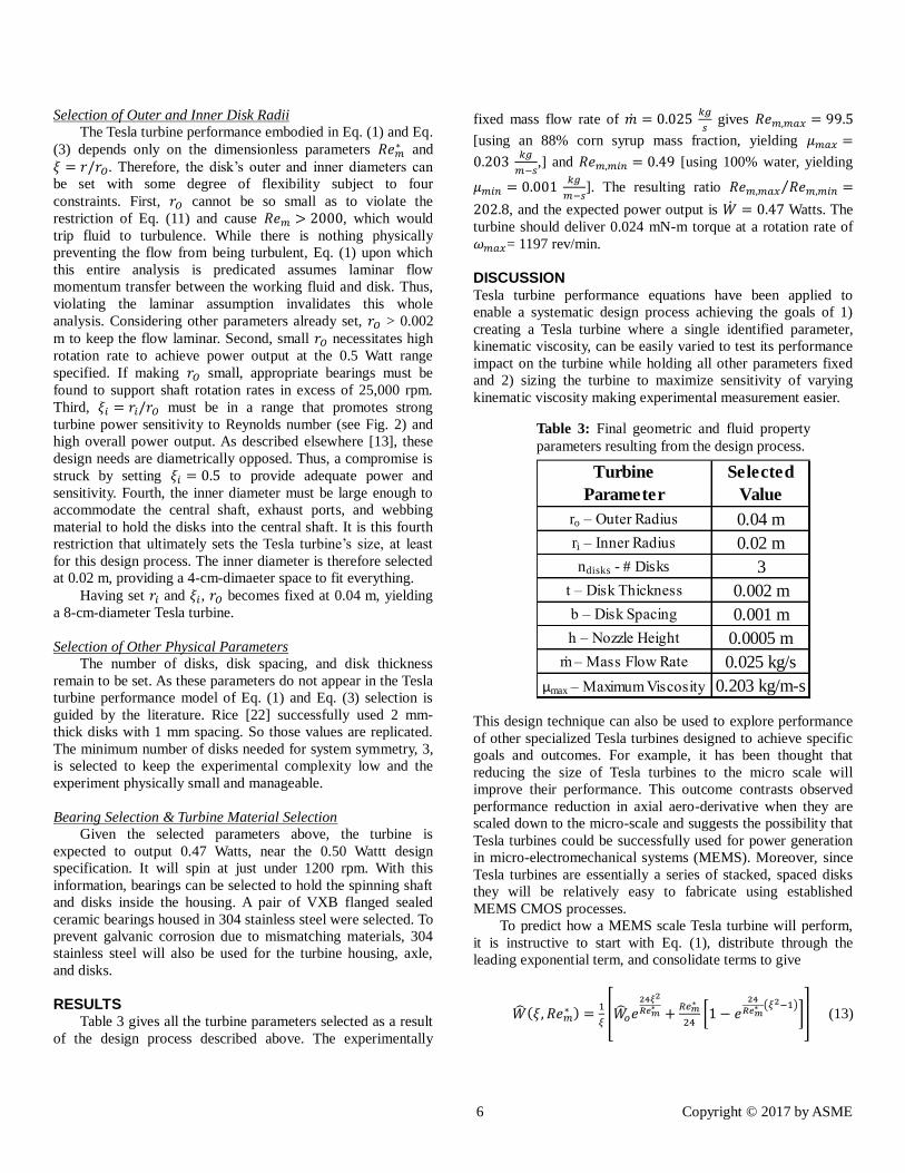
RESULTS Table 3 gives all the turbine parameters selected as a result
of the design process described above. The experimentally
fixed mass flow rate of �̇� = 0.025 𝑘𝑔
𝑠 gives 𝑅𝑒𝑚,𝑚𝑎𝑥 = 99.5
[using an 88% corn syrup mass fraction, yielding 𝜇𝑚𝑎𝑥 =
0.203 𝑘𝑔
𝑚−𝑠,] and 𝑅𝑒𝑚,𝑚𝑖𝑛 = 0.49 [using 100% water, yielding
𝜇𝑚𝑖𝑛 = 0.001 𝑘𝑔
𝑚−𝑠]. The resulting ratio 𝑅𝑒𝑚,𝑚𝑎𝑥 𝑅𝑒𝑚,𝑚𝑖𝑛⁄ =
202.8, and the expected power output is �̇� = 0.47 Watts. The
turbine should deliver 0.024 mN-m torque at a rotation rate of
𝜔𝑚𝑎𝑥= 1197 rev/min.
DISCUSSION Tesla turbine performance equations have been applied to
enable a systematic design process achieving the goals of 1)
creating a Tesla turbine where a single identified parameter,
kinematic viscosity, can be easily varied to test its performance
impact on the turbine while holding all other parameters fixed
and 2) sizing the turbine to maximize sensitivity of varying
kinematic viscosity making experimental measurement easier.
This design technique can also be used to explore performance
of other specialized Tesla turbines designed to achieve specific
goals and outcomes. For example, it has been thought that
reducing the size of Tesla turbines to the micro scale will
improve their performance. This outcome contrasts observed
performance reduction in axial aero-derivative when they are
scaled down to the micro-scale and suggests the possibility that
Tesla turbines could be successfully used for power generation
in micro-electromechanical systems (MEMS). Moreover, since
Tesla turbines are essentially a series of stacked, spaced disks
they will be relatively easy to fabricate using established
MEMS CMOS processes.
To predict how a MEMS scale Tesla turbine will perform,
it is instructive to start with Eq. (1), distribute through the
leading exponential term, and consolidate terms to give
�̂�(𝜉, 𝑅𝑒𝑚∗ ) =
1
𝜉[�̂�𝑜𝑒
24𝜉2
𝑅𝑒𝑚∗
+𝑅𝑒𝑚
∗
24[1 − 𝑒
24
𝑅𝑒𝑚∗ (𝜉2−1)
]] (13)
Turbine
Parameter
Selected
Value
ro – Outer Radius 0.04 m
ri – Inner Radius 0.02 m
ndisks - # Disks 3
t – Disk Thickness 0.002 m
b – Disk Spacing 0.001 m
h – Nozzle Height 0.0005 m
ṁ – Mass Flow Rate 0.025 kg/s
μmax – Maximum Viscosity 0.203 kg/m-s
Table 3: Final geometric and fluid property
parameters resulting from the design process.

7 Copyright © 2017 by ASME
The dimensionless inner/outer diameter ratio is bounded 0 < ξ <
1, and any arbitrary representative value in this range can be
selected, ξ = 0.1. The key question is what happens to �̂� when
𝑅𝑒𝑚∗ approaches 0; in other words, what is the trend in
momentum transfer between the working fluid and the turbine
disks as the turbine shrinks in size. Putting 𝑅𝑒𝑚∗ → 0 into Eq.
(13) yields
�̂�(𝜉 = 0.1, 𝑅𝑒𝑚∗ → 0) =
1
0.1[�̂�𝑜𝑒
24(0.1)2
0 +0
24[1 − 𝑒
24
0((0.1)2−1)]] (14)
The last term in parentheses goes to zero, giving
�̂�(𝜉 = 0.1, 𝑅𝑒𝑚∗ → 0) =
1
0.1[�̂�𝑜𝑒∞ +
0
24[1 − 0]] (15)
Finally, the lead term in parenthesis with coefficient �̂�𝑜 goes to
infinity.
�̂�(𝜉 = 0.1, 𝑅𝑒𝑚∗ → 0) =
�̂�𝑜𝑒∞
0.1 (16)
While 𝑅𝑒𝑚∗ cannot literally reach 0 (without stopping the flow,
the null solution), it can be driven to arbitrarily small values.
What does this result mean for the effectiveness of fluid-disk
momentum transfer? Recall that �̂� is the velocity difference
between the working fluid and the turbine disks. Higher �̂�
implies high velocity difference, which means high momentum
transfer to the disks, increased turbine efficiency, and higher
power output. In short, low Reynolds number corresponds to
high Tesla turbine performance, suggesting MEMS Tesla
turbines as an important new area for research exploration.
Without building a MEMS-scale Tesla turbine, it is
nonetheless possible to use scaling laws with a macro-scale
experimental turbine to explore MEMS-scale Tesla turbine
performance and behavior. Using liquid working fluid in the
macro-scale turbine and matching 𝑅𝑒𝑚∗ and 𝜉 allows replication
of a much smaller turbine running products of combustion.
Consider the inlet conditions for the millimeter-scale aero-
derived turbine in Epstein [46]. Products of combustion
(modeled as air) enter the turbine at 4 atm and 1600 K. At this
temperature and pressure, 𝜌𝑎𝑖𝑟 = 0.8815 kg/m3 and 𝜇𝑎𝑖𝑟 = 5.88
x 10-5
kg/m-s. Epstein claims a working fluid mass flow rate of
1.8 x 10⁻⁴
kg/s [46]. For comparison, consider the Reynolds
number obtained in the 8-cm-diameter Tesla turbine designed
via the process above running Propylene Glycol working fluid.
𝑅𝑒𝑚,8𝑐𝑚 =�̇�
𝜋𝑛𝜇𝑟𝑜=
0.162 𝑘𝑔
𝑠
𝜋(3)(0.004𝑘𝑔
𝑚∙𝑠)(0.04 𝑚)
= 212.2 (17)
Applying similarity arguments, a micro-turbine with the same 𝜉
and 𝑅𝑒𝑚 as the 8-cm-diameter Tesla turbine should
demonstrate the same efficiency (dimensionless power) output.
𝑅𝑒𝑚,8𝑐𝑚 = 𝑅𝑒𝑚,𝑀𝐸𝑀𝑆 =�̇�
𝜋𝑛𝜇𝑟𝑜 (18)
Using similarity arguments to solve for the disk radius of a
millimeter-scale Tesla turbine with products of combustion as
working fluid gives
𝑟𝑜 =�̇�
𝜋𝑛𝜇𝑅𝑒𝑚,𝑀𝐸𝑀𝑆=
1.8 ×10⁻⁴𝑘𝑔
𝑠
𝜋(3)(5.88 ×10⁻⁵ 𝑘𝑔
𝑚∙𝑠)(212.2)
= 0.00153 𝑚 (19)
Thus, the characteristic disk radius of this millimeter-scale
turbine with the same performance as the 8-cm-diameter Tesla
turbine running Ethylene Glycol would be about 3 mm. That
similarity-based characteristic diameter can be further driven
down by increasing the working fluid pumping rate through the
8-cm-diameter turbine.
CONCLUSION This paper applies analytical equations for turbine
performance as the foundation to present a systematic Tesla
turbine design process. To our knowledge, no Tesla turbine
design process based in foundational theory has ever been
published in the peer reviewed engineering literature. The
process is shown to be flexible, allowing an engineering
designer to select and address goals beyond simply maximizing
turbine output power. This process was demonstrated in this
paper by creating a Tesla turbine design where a single
identified parameter, Reynolds number, can be easily varied to
test its performance impact on the turbine while holding all
other parameters fixed. The secondary goal of this design
process is to size the turbine to maximize sensitivity to changes
in Reynolds number to make experimental measurement more
facile.
Reynolds number will be modulated at fixed working fluid
mass flow rate using a two-component liquid mixture of water
and corn syrup where kinematic viscosity is adjusted by
changing the mass fraction of corn syrup. The turbine design
results in 8 cm outer diameter and 4 cm inner dimeter disks.
The working fluid mass flow rate through the turbine is
�̇� = 0.025 𝑘𝑔
𝑠, giving a range of accessible Reynolds numbers
from is 0.49 < 𝑅𝑒𝑚 < 99.5 for a Reynolds number ratio of
𝑅𝑒𝑚,𝑚𝑎𝑥 𝑅𝑒𝑚,𝑚𝑖𝑛⁄ = 202.8 , more than two orders of
magnitude increase and spanning the lower part of the laminar
range. The turbine’s expected power output is �̇� = 0.47 Watts
with a delivered torque of 0.024 mN-m at a rotation rate of
𝜔𝑚𝑎𝑥= 1197 rev/min.
Combining the analytical equations underpinning the
design process with similarity arguments, it is shown that
shrinking the scale of a Tesla turbine drives the Reynolds
number toward 0. The resulting velocity difference between the
working fluid and the turbine disks gets driven toward infinity,
which makes momentum transfer and the resulting turbine
efficiency extremely high. In other words, unlike conventional
turbines whose efficiency drops as they are scaled down, the

8 Copyright © 2017 by ASME
performance of Tesla turbines will increase as they are made
smaller.
Finally, it is shown through similarity scaling arguments
that the 8-cm-dimater turbine resulting from the design process
of this paper running liquid Ethylene Glycol working fluids
could be used to evaluate and approximate the performance of a
3-mm-diameter Tesla turbine powered by products of
combustion.
NOMENCLATURE b = Spacing between rotors
h = Nozzle height
ṁ = Mass flow rate through turbine
ṁc = Mass flow rate in a channel between disk rotor pairs
ndisk = Number of rotor disks
r = Rotor radius
ri = Rotor radius at the turbine inlet (outer radius)
ro = Rotor radius at the turbine outlet (inner radius)
Rem = Reynolds number based on channel mass flow rate
Rem* = Modified Reynolds number [ 2𝑏
𝑟𝑜𝑅𝑒𝑚 = 𝑅𝑒𝑚
∗ ]
Rem,8cm = Reynolds number for an 8-cm-diameter disk turbine
Rem,max = Reynolds number for water at ṁ fixed for Rem,min
Rem,MEMS = Reynolds number for a MEMS-scale disk turbine
Rem,min = Reynolds no. for viscous mixture at pump-limited ṁ
t = Disk rotor thickness
Ui = Rotor surface tangential velocity at r = ri
Uo = Rotor surface tangential velocity at r = ro
VBNi = Viscosity blending number of component i
VBNmixture = Viscosity blending number of the mixture
vθ,i = θ-direction (tangential) working fluid velocity at r = ri
vθ,o = θ-direction (tangential) working fluid velocity at r = ro
Ẇ = Turbine mechanical output power
Ŵ(ξ,Rem*) = Dimensionless tangential velocity difference
between the disk rotor & working fluid (vθ,- U)/Uo
at any radial location
Ŵi = Dimensionless tangential velocity difference at r = ri
Ŵo = Dimensionless tangential velocity difference at r = ro
Γ = Torque
η = Turbine energy conversion efficiency
μ = Working fluid dynamic viscosity
μair = Dynamic viscosity of air
μmax = Viscosity of the most viscous 2-component working fluid
μmin = Viscosity of water (least viscous 2-component working fluid)
νi = Dynamic viscosity of component i
νmixture = Dynamic viscosity of the mixture
ξ = Dimensionless radial coordinate = r/ro
ξi = Dimensionless radius ratio = ri/ro
ρair = Density of air
ω = Angular velocity (rad/sec)
ωmax = Maximum angular velocity (rad/sec)
ACKNOWLEDGMENTS
We acknowledge in-kind donations of materials and
volunteer time by Engineer Inc, a Tennessee-based engineering
education technology company. Engineer Inc creates
inexpensive teaching laboratory equipment for engineering
courses: www.engineerinc.net.
This paper’s undergraduate authors are members of the
Tennessee Undergraduate Researcher Network (TURN) at
TSU, an organization that fast-tracks undergraduates into
meaningful early research experiences. This project
demonstrates the Undergraduate Researcher Incubator
Hypothesis [47, 48].
REFERENCES
[1] Jacobson, R., “Tesla Bladeless Pumps and Turbines,”
Proceedings of the 26th Intersociety Energy Conversion
Engineering Conference, Vol. 4, Piscataway, NJ, 1991, pp. 445-
450.
[2] Wakeman, T., Tabakoff, W., “Turbomachinery Affected by
Environmental Solid Particles,” Paper 79-0041, Proceedings of
the 17th
AIAA Aerospace Sciences Meeting, New Orleans, LA,
January 15-17, 1979.
[3] Grant, G., Tabakoff, W., “Erosion Prediction in
Turbomachinery Resulting from Environmental Solid
Particles,” AIAA Journal of Aircraft, Vol. 12, May 1975, pp.
471-478.
[4] Ghenaiet, A., “Study of Particle Ingestion through Two-
Stage Gas Turbine,” Paper GT2014- 25759, Proceedings of the
ASME Turbine Technical Conference and Exposition, Vol. 2C,
Düsseldorf, Germany, June 16-20, 2014.
[5] Tabakoff, W., Hamed, A., Metwally, M., “Effect of Particle
Size Distribution on Particle Dynamics and Blade Erosion in
Axial Flow Turbines,” Journal of Gas Turbine and Power, Vol.
113, Oct. 1991, pp. 607–615.
[6] Rice, W., “Tesla Turbomachinery,” Proceedings of the 4th
International Tesla Symposium, Serbian Academy of Sciences
and Arts, Belgrade, Yugoslavia, Sept. 22-25, 1991.
[7] Gupta, H. E., Kodali, S. P., “Design and Operation of Tesla
Turbo Machine - A State of the Art Review,” International
Journal of Advanced Transport Phenomena, Vol. 2, No. 1, 2013
pp. 7-14.
[8] Tahil, W., “Theoretical Analysis of a Disk Turbine,” Tesla
Engine Builder’s Association (TEBA) Newsletter, Vol. 15, 1998,
pp 18-19.
[9] Tahil, W., “Theoretical Analysis of a Disk Turbine (2),”
Tesla Engine Builder’s Association (TEBA) Newsletter, Vol. 16,
1999, pp 15-16.
[10] Carey, V. P., “Assessment of Tesla Turbine Performance
for Small Scale Solar Rankine Combined Heat and Power
Systems,” Journal of Engineering for Gas Turbines and Power,
Vol. 132, No.3, pp. 122301-1 – 122301-8.
[11] Carey. V. P., “Assessment of Tesla Turbine Performance
for Small Scale Solar Rankine Combined Heat and Power
Systems,” IMECE2009-10814, Proceedings of the 2009 ASME
International Mechanical Engineering Congress & Exposition,
Lake Buena Vista, Florida, November 13-19, 2009.
[12] Krishnan, V. G., Romanin, V., Carey, V. P., Maharbiz, M.
M., “Design and scaling of microscale Tesla turbines,” Journal
of Micromechanics and Microengineering, Vol. 23, 2013.
9 Copyright © 2017 by ASME
[13] Traum, M. J., Hadi, F., Akbar, M. K., “Extending
‘Assessment of Tesla Turbine Performance’ Model for
Sensitivity-Focused Experimental Design,” ASME Journal of
Energy Resources Technology, Submitted, 2017.
[14] Fréchette, L. G., Lee, C., Arslan, S., Liu, Y-. C-, “Design
of a microfabricated Rankine cycle steam turbine for power
generation,” IMECE2003-42082, Proceedings of the 2003
ASME International Mechanical Engineering Congress and
Exposition, Washington, DC, November 15–21, 2003, pp. 335-
344.
[15] Epstein, A. H., “Millimeter-scale, micro-electro-
mechanical systems gas turbine engines,” ASME Journal of
Engineering for Gas Turbines and Power, Vol. 126, No. 2,
2004, pp. 205– 226.
[16] Lee, C., Fréchette, L. G., “A silicon microturbopump for a
rankine-cycle power generation microsystem—Part I:
Component and system design,” Journal of
Microelectromechanical Systems, Vol. 20, No. 1, 2011, pp. 312-
325.
[17] McKeathen, J. E., Reidy, R. F., Boetcher, S. K., Traum, M.
J., “A Cryogenic Rankine Cycle for Space Power Generation,”
Paper Number 2009-4247, Proceedings of the 41st AIAA
Thermophysics Conference, San Antonio, TX, June 22 - 25,
2009.
[18] Tesla, N, United States of America Patent 1,061,206, 1913.
[19] Swithenbank, A. M. “The Tesla Boundary Layer Turbine,”
Web URL: http://www.stanford.edu/~hydrobay/lookat/tt.html,
accessed 3/13/2017.
[20] Boyd, K. E., Rice, W., “Laminar Inward Flow of an
Incompressible Fluid Between Rotating Disks With Full
Peripheral Admission,” Journal of Applied Mechanics, Vol. 35,
No. 2, 1968, pp 229-237.
[21] Matsch, L., Rice, W., “An Asymptotic Solution for
Laminar Flow of an Incompressible Fluid Between Rotating
Disks,” Journal of Applied Mechanics, Vol. 35, No. 1, 1968, pp.
155-159.
[22] Rice, W., “An Analytical and Experimental Investigation
of Multiple-Disk Turbines,” Journal of Engineering for Power,
Transactions of the ASME, Vol. 87, No. 1, 1965, pp. 29-36.
[23] Lawn, M. J., Rice, W., “Calculated Design Data for the
Multiple-Disk Turbine Using Incompressible Fluid,” Journal of
Fluids Engineering, Vol. 96, No. 3, 1974, pp. 252-258.
[24] Truman, C. R., Rice, W., Jankowski, D. F., “Laminar
Throughflow of Varying-Quality Steam Between Corotating
Disks,” Journal of Fluids Engineering, Vol. 100, No, 2, 1978,
pp. 194-200.
[25] Hoya, G. P., Guha, A., “The design of a test rig and study
of the performance and efficiency of a Tesla disc turbine,”
Proceedings of the Institution of Mechanical Engineers, Part A:
Journal of Power and Energy, Vol. 223, No. 4, 2009, pp. 451-
465.
[26] Guha, A., Sengupta, S., “Similitude and scaling laws for
the rotating flow between concentric discs,” Proceedings of the
Institution of Mechanical Engineers, Part A: Journal of Power
and Energy, Vol. 228, June 2014, pp. 429-439.
[27] Deng, Q., Qi, W., Feng, Z., “Improvement of a Theoretical
Analysis Method for Tesla Turbines,” GT2013-95425, 2013
ASME Turbo Expo, San Antonio, TX, June 3–7, 2013.
[28] Qi, W., Deng, Q., Feng, Z., Yuan, Q., “Influence of Disc
Spacing Distance on the Aerodynamic Performance and Flow
Field of Tesla Turbines,” GT2016-57971, 2016 ASME Turbo
Expo, Seoul, South Korea, June 13–17, 2016.
[29] Guha, A., Sengupta, A., “The fluid dynamics of work
transfer in the non-uniform viscous rotating flow within a Tesla
disc turbomachine,” Physics of Fluids, Vol. 26, 2014.
[30] Yang, Z., Weiss, H. L., Traum, M. J., “Gas Turbine
Dynamic Dynamometry: A New Energy Engineering
Laboratory Module,” Proceedings of the 2013 American
Society for Engineering Education North Midwest Section
Conference, Fargo, North Dakota, October 17-18, 2013.
[31] Yang, Z., Weiss, H. L., Traum, M. J., “Dynamic
Dynamometry to Characterize Disk Turbines for Space-Based
Power,” Proceedings of the 23rd Annual Wisconsin Space
Conference, Milwaukee Wisconsin, August 15-16, 2013.
[32] Usman, M., Khan, S., Ali, E., Maqsood, M. I., Nawaz, H.,
“Modern improved and effective design of boundary layer
turbine for robust control and efficient production of green
energy,” Journal of Physics: Conference Series, Vol. 439, 2013.
[33] Beans, E. W. “Performance Characteristics of a Friction
Disk Turbine,” Doctoral Dissertation, Pennsylvania State
University, 1961.
[34] Leaman, A. B. “The Design, Construction and
Investigation of a Tesla Turbine,” Master’s Thesis, University
of Maryland, 1950.
[35] Gupta, E. H., Kodali, S. O., “Design and Operation of
Tesla Turbo machine - A state of the art review,” International
Journal of Advanced Transport Phenomena, Vol. 2, No. 1, 2013
[36] Lampart, P., Jędrzejewski, Ł., “Investigations of
Aerodynamics of Tesla Bladeless Microturbines,” Journal of
Theoretical and Applied Mechanics, Vol. 49, No. 2, 2011, pp.
477-499.
[37] Pandey, R. J., Pudasaini, S., Dhakal, S., Uprety, R. B.,
Neopane, H. P., “Design and Computational Analysis of 1 kW
Tesla Turbine,” International Journal of Scientific and
Research Publications, Vol. 4, Issue 11, 2014.
[38] Romanin, V. D., Krishnan, V. G., Carey, V. P., Maharbiz,
M. M., “Experimental and Analytical Study of Sub-Watt Scale
Tesla Turbine Performance,” IMECE2012-89675, Proceedings
of the 2010 ASME International Mechanical Engineering
Congress and Exposition, Houston, TX, November 9–15, 2012,
pp. 1005-1014.
[39] Wee, T., Rahman, A. A., Shy, J. F., Eng, A. L.,
“Optimization of Tesla turbine using Computational Fluid
Dynamics approach,” Proceedings of the 2011 IEEE
Symposium on Industrial Electronics and Applications, 2011,
pp. 477-480.
[40] Ho-Yan, B. P., “Tesla turbine for pico hydro applications,”
Guelph Engineering Journal, Vol. 4, 2011, pp. 1-8.
[41] Cross, N., Engineering Design Methods – Strategies for
Product Design, 4th Edition, Wiley, 2008.
10 Copyright © 2017 by ASME
[42] Hasan, A., Benzamia, A., “Investigating the Impact of Air
Temperature on the Performance of a Tesla Turbine Using CFD
Modeling,” International Journal of Engineering Innovation &
Research, Vol. 3, Issue 6, 2014, pp 794-802.
[43] Maples, R. E., Petroleum Refinery Process Economics,
2nd Edition, Pennwell Books, 2000.
[44] Chirife, J., Buera, M. P., “A simple model for predicting
the viscosity of sugar and oligosaccharide solutions,” Journal
of Food Engineering, Vol. 33, No. 3-4, 1997, pp. 221-226.
[45] White, F. M., Fluid Mechanics, 7th Edition, McGraw Hill,
2011, p. 382.
[46] Epstein, A. H. “Millimeter-scale, MEMS gas turbine
engines,” Proceedings of the 2003 ASME International Joint
Power Generation Conference, 2003.
[47] Traum, M. J., Karackattu, S. L. Houston Jackson, D.,
McNutt, J. D., “Organization to Fast-Track Undergraduate
Students Into Engineering Research via Just-In-Time
Learning,” Proceedings of the Conference On Being an
Engineer: Cognitive Underpinnings of Engineering Education,
Lubbock, TX, February 1-2, 2008.
[48] Traum, M. J., Karackattu, S. L., “The Researcher
Incubator: Fast-tracking Undergraduate Engineering Students
into Research via Just-in-Time Learning,” Paper Number 09-
33, Proceedings of the 2009 ASEE Gulf-Southwestern Section
Annual Conference, Waco, TX, March 18 – 20, 2009.