method statement - rowad national plastic company · method statement (generic unless otherwise...
TRANSCRIPT

METHOD STATEMENT
For the Installation of HDPE and LLDPE Geomembrane
Please Note : This document is generic only and for use only on projects where Rowad itself is directly
involved with the Installation work on site .
If the document is used as a reference by 3rd or other parties any comments herein which relate to Rowad
Obligations and actions strictly do not apply unless otherwise agreed to in writing.
Contacts :
Website: www.rowadgeo.com
Enquiries: [email protected]
Telephone: 00966 (0)13 812 1360
P. O. Box 14164 Dammam 31424. Kingdom of Saudi Arabia
Road No. 42, 2nd Industrial City, Dammam, Kingdom of Saudi Arabia
(DOC MS. Dated 01 October 2016 Version 05)

Table of Contents
SECTION A - INTRODUCTION
Quality Statement........................................................................................................ Organization ................................................................................................................
SECTION B – MANUFACTURING QUALITY CONTROL
HDPE and LLDPE Geomembrane Quality Control ..................................................... Raw Materials.............................................................................................................. Geomembrane Testing................................................................................................ Extrusion Rod .............................................................................................................. Storage and Handling.................................................................................................. Flowchart – Geomembrane Quality Control Program .................................................
SECTION C – METHOD STATEMENT
HDPE and LLDPE Geomembrane Quality Control ..................................................... Delivery, Storage and Handling .................................................................................. On-Site Material Inspection ......................................................................................... Panel Identification and Layout ................................................................................... Equipment ................................................................................................................... Subgrade Preparation ................................................................................................. Anchoring .................................................................................................................... Deployment ................................................................................................................. Panel placement.......................................................................................................... Preparation for Welding............................................................................................... Welding Procedures .................................................................................................... Seam Inspection and Repair .......................................................................................
SECTION D – INSTALLATION QUALITY ASSURANCE
Conformance Testing .................................................................................................. Non-Destructive Testing.............................................................................................. Destructive Testing...................................................................................................... Defects and Repairs.................................................................................................... Geomembrane Acceptance ........................................................................................ Flowchart – Geomembrane Welding and Installation .................................................
SECTION E – ROWAD STANDARD MATERIAL SPECS & MANUFACTURING QC REQUIREMENTS
SECTION F – ROWAD STANDARD INSTALLATION QC & QUALITY ASSURANCE REQUIREMENTS
SECTION G – SITE SPECIFIC REQUIREMENTS
CONVERSIONS USED in this MANUAL:
40 mil = 1.0 mm
1 inch = 25.4 mm
1 foot = 304.8 mm
Degree Fahrenheit to Centigrade = (F-32) x 5/9 = C
1 Psi = 6.894 kPa~

SECTION A
INTRODUCTION
Qua lity S t a t e m e n t
Rowad Geo is dedicated to an objective of continuous commitment to quality. This dedication begins with the manufacture of the geomembrane material and ends only when our customer has accepted the liner. The employees of Rowad Geo, therefore, endorse and require a policy of Total Quality. This policy is based on the principle that quality is the fundamental responsibility of every department and is carried out by each person in that department.
Programs and procedures designed to implement this quality principle are developed by the Quality Control Department and are utilized by every employee of the Company.
Rowad Geo laboratories are accredited by the Geosynthetic Accreditation Institute Lab Accreditation Program (GAI-LAP). Rowad Geo Manufacturing and Installation processes are ISO 9001:2008 registered.
Organi zati on
Persons performing quality-related functions have sufficient authority and organizational freedom to: (1) identify quality programs; (2) initiate, recommend or provide solutions through designated channels; (3) verify implementation of solutions; (4) control further work when required. The person responsible for defining and measuring the overall effectiveness of the Quality Program is the Quality Control Manager.
Key personnel include the Chairman, General Manager – Operations, Manufacturing Manager, Quality Control Manager, Product Development Manager, Regional Managers, Project Managers, and the Safety Manager. Resumes of key personnel are provided when requested or required by project specifications.
SECTION B
M ANUFACTURING QUALITY CONTROL 1. HDPE and LLDPE Geomembrane Quality Control
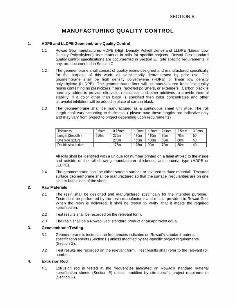
1.1 Rowad Geo manufactures HDPE (High Density Polyethylene) and LLDPE (Linear Low Density Polyethylene) liner material in rolls for specific projects. Rowad Geo standard quality control specifications are documented in Section E. Site specific requirements, if any, are documented in Section G.
1.2 The geomembrane shall consist of quality resins designed and manufactured specifically for the purpose of this work, as satisfactorily demonstrated by prior use. The geomembrane shall be high density polyethylene (HDPE) or linear low density polyethylene (LLDPE). The geomembrane liner will be manufactured from first quality resins containing no plasticizers, fillers, recycled polymers, or extenders. Carbon black is normally added to provide ultraviolet resistance, and other additives to provide thermal stability. If a color other than black is specified then color concentrates and other ultraviolet inhibitors will be added in place of carbon black.
1.3 The geomembrane shall be manufactured as a continuous sheet 8m wide. The roll length shall vary according to thickness. ( please note these lengths are indicative only and may vary from project to project depending upon requirements)
Thickness 0.5mm 0.75mm 1.0mm 1.5mm 2.0mm 2.5mm 3.0mm
Length (Smooth ) 350m 225m 170m 110m 80m 70m 50
One side texture 200m 150m 100m 80m 60m 50
Double side texture 175m 125m 90m 70m 50m 40
All rolls shall be identified with a unique roll number printed on a label affixed to the inside and outside of the roll showing manufacturer, thickness, and material type (HDPE or LLDPE).
1.4 The geomembrane shall be either smooth-surface or textured surface material. Textured surface geomembrane shall be manufactured so that the surface irregularities are on one side or both sides of the sheet.
2. Raw Materials
2.1 The resin shall be designed and manufactured specifically for the intended purpose. Tests shall be performed by the resin manufacturer and results provided to Rowad Geo. When the resin is delivered, it shall be tested to verify that it meets the required specification.
2.2 Test results shall be recorded on the relevant form.
2.3 The resin shall be a Rowad Geo. standard product or an approved equal.
3. Geomembrane Testing
3.1 Geomembrane is tested at the frequencies indicated on Rowad’s standard material specification sheets (Section E) unless modified by site-specific project requirements (Section G).
3.2 Test results are recorded on the relevant form. Test results shall refer to the relevant roll number.
4. Extrusion Rod
4.1 Extrusion rod is tested at the frequencies indicated on Rowad’s standard material specification sheets (Section E) unless modified by site-specific project requirements (Section G).

SECTION B
4.2 Test results shall be recorded on the relevant form.
5. Storage and Handling
5.1 Rolls of material are handled with equipment that will not damage the membrane. Fabric straps are attached to the rolls of material to be used for unloading at the job site.
5.2 The storage area shall be reasonably flat and free of sharp rocks or other objects that could damage the material.
SECTION B
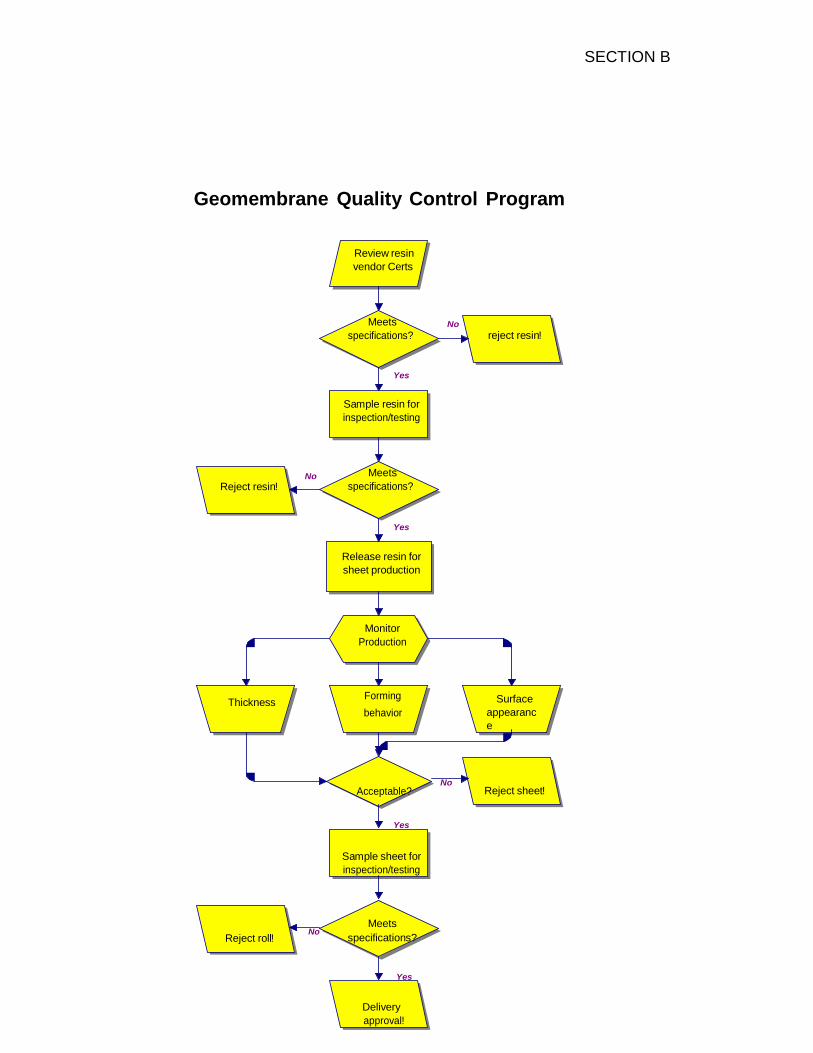
Geomembrane Quality Control Program
Review resin
vendor Certs
Meets
specifications?
No
reject resin!
Yes
Sample resin for
inspection/testing
No
Reject resin!
Meets
specifications?
Yes
Release resin for
sheet production
Monitor
Production
Thickness Forming
behavior
Surface
appearanc
e
No Acceptable?
Reject sheet!
Yes
Sample sheet for
inspection/testing
Reject roll!
Meets No
specifications?
Yes
Delivery
approval!

SECTION C
METHOD STATEMENT
(Generic Unless Otherwise Stated)
1. HDPE and LLDPE Geomembrane Quality Control
1.1 Rowad Geo installs HDPE (High Density Polyethylene) and LLDPE (Linear Low Density Polyethylene) geomembranes.
2. Delivery, Storage and Handling
2.1 Prior to unloading, the handling equipment is inspected to verify that it will not damage the material. Fabric straps or other approved apparatus are used for handling of material.
2.2 Rolls must be examined upon unloading to insure that there is no damage to the material and to assure that the correct material for the job has been received.
2.2 The storage area must be secure to prevent vandalism and thefts and must be such that rolls are not likely to be damaged by passing vehicles. The storage area shall be such that continuous contact with water is minimized. The storage area shall be smooth, flat and free of rocks or other objects that could cut or puncture the liner. Rolls of geomembrane do not need protection from normal weather conditions.
3. On-site Material Inspection
3.1 Identification labels on material rolls shall be inspected and roll numbers recorded for future documentation. The roll number is unique and shall be used to identify the roll in QC testing and to determine which panels are cut from an individual roll.
4. Panel Identification and Layout
4.1 As part of the initial job planning a panel layout drawing shall be prepared that shows how rolls of liner material may be assembled and joined to form the finished liner. Each panel of liner shall be assigned a number for future reference.
4.2 Proposed Panel Layout Drawings are intended as a guideline, during Project Planning, to indicate the basic layout concepts and allow for feedback between the Owner, Liner Installer, Engineer, etc. Actual finished Panel Layout (i.e. “As-Built”) may differ from the proposed panel layout due to field evaluations of actual site conditions. Such conditions may include considerations for construction coordination between contractors, weather (i.e. wind direction), minimization of field seaming and miscellaneous other factors.
5. Equipment
5.1. Welding Equipment: The Geomembrane Contractor shall provide welding equipment showing extrudate temperature (extrusion welder), wedge temperature (wedge welder) or nozzle temperature (hot air). Sufficient equipment shall available to avoid delaying work, and shall be supplied by a power source capable of providing constant voltage under a combined-line load. Generators with rubber tires are allowed on the geomembrane. Prior to placement on the geomembrane, tires should be inspected to assure that there are no sharp objects adhered to them that could result in damage to the geomembrane. Scrap membrane should be placed under the generator to ensure that any spilled fluids will not come into contact with the geomembrane.
5.2. Punch Press: The Geomembrane Contractor shall provide a punch press for the on-site preparation of specimens for testing.
5.3. Field Tensiometer: The Geomembrane Contractor shall provide a tensiometer for on-site shear and peel testing of geomembrane seams. The tensiometer shall be in good working order, built to ASTM specs, and calibrated within one year. The tensiometer shall be motor driven and capable of a 2 and 20 in/min jaw separation rate. It shall be capable of measuring the force exerted between the jaws and have a digital readout.

SECTION C
5.4. Vacuum Box: The Geomembrane Contractor shall provide a vacuum box for on-site testing of geomembrane seams. The vacuum box shall have a transparent viewing window on top and a soft closed-cell neoprene gasket attached to the bottom. The housing shall be rigid and equipped with a bleed valve and vacuum gauge. A separate vacuum source shall be connected to the vacuum box. The equipment shall be capable of inducing and holding a vacuum of 5 psi.
5.5. Gauge and Air Pump: The Geomembrane Contractor shall provide an air pump capable of achieving a minimum of 35 psi. Gauges must be capable of registering at least 35 psi.
5.6. Miscellaneous Equipment: Small tools will include hook blade utility knives, scissors with rounded points and silicone or rubber rollers. Step up transformer per generator will be used to assure constant voltage to the welding equipment as necessary.
6. Subgrade Preparation
6.1 The subgrade is prepared by the owner or by the contractor according to the specifications. The surface must be smooth, with no rapid changes of grade such as steps or settlement next to concrete structures. All slopes and surfaces must be compacted to ensure the integrity of the membrane. While the geomembrane is designed to withstand some differential settlement, an analysis of these areas must be made by the engineer to ensure that the stresses on the membrane are acceptable.
6.2 The surface of the subgrade must be free of sharp rocks, penetrating debris or other appurtenances that could damage the membrane. Typically, finished subgrade is achieved using a smooth steel drum roller or other method as approved by the Project Engineer. Under certain conditions a cushion geotextile can be evaluated and approved for use by the Project Engineer, to provide protection for the geomembrane.
6.3 After acceptance by the Owner’s Representative, Rowad shall perform a visual inspection of the subgrade surface to determine that it is suitable to be lined. Rowad’s acceptance of the finished subgrade surface shall be recorded on the relevant form.
7. Anchoring
7.1 The membrane is to be anchored as shown on the plans and approved drawings. The anchor trench is excavated by the owner or by the contractor as shown on the approved contract drawings. Attention must be paid to the stability of the soil being excavated. Excavation of trenches should be coordinated with the geomembrane installation to avoid excessive exposure to weathering prior to installation. Trenches that collapse, deteriorate, or become saturated, may require rework by the contractor.
7.2 Upon placement of geomembrane panels, the anchor trench must be partially backfilled by the contractor immediately to prevent panel slippage, wind uplift or blowout that could result in liner damage. If immediate backfilling of trenches is not possible, sandbag loading should be used to provide temporary ballast. Final backfilling and compaction, by the Owner or contractor, should commence only after the geomembrane has had time to dissipate manufacturing orientation and settle into its final position. Final backfilling of the anchor trench shall be completed per the specification.
8. Deployment
8.1 Geomembrane panels shall be unrolled using methods that will not damage, stretch, or crimp the geomembrane and shall protect the underlying subsurface from damage. The methods used shall minimize wrinkles. If necessary a smooth piece of geomembrane may be used as a rub sheet to facilitate deployment of geosynthetic layers. The rub sheet does not need to run the entire length of the slope, only the top crest and first few feet of the slope need to be covered to facilitate deployment. Ballast that will not damage the geomembrane shall be used to prevent uplift due to wind.

SECTION C
8.2 Panels shall be oriented perpendicular to the line of the slope crest (i.e., down and not across slope). If panels must be placed across slopes then they shall be shingled such that the upper panel is overlapped above the lower panel. For slopes steeper than 10:1, cross seams parallel to the crest or toe will be located at least 1 foot from the crest or the toe of slope or at such a distance where a fully integrated weld can be performed in restricted locations. Cross seams on slopes should be minimized, but are acceptable when staggered throughout the slope.
8.3 Each panel deployed shall be assigned a simple and logical identifying code consistent with the submitted panel layout drawings. No more panels shall be deployed in one day than can be welded during that same day. Tack welding may be acceptable as a temporary measure. However, when possible tack welded panels shall not be left overnight.
8.4 Personnel walking on the geomembrane shall not wear types of shoes that could damage the geomembrane. Smoking shall not be permitted on the geomembrane.
8.5 Vehicular traffic on the geomembrane shall be minimized. Equipment shall not damage the geomembrane by handling, trafficking, leakage of hydrocarbons, or any other means. The geomembrane surface shall not be used as a work area, for preparing patches, storing tools and supplies, or other uses. A protective cover may be spread out as a work surface.
8.6 Rowad uses low ground pressure devices such as ATV’s and tractors to help facilitate deployment over other geosynthetic layers and to reduce the potential for strain related injuries among its field personnel. Low ground pressure devices are machines with less than 7 psi per wheel when carrying a driver weighing approximately 150 lbs. The typical specification for equipment working directly over the geosynthetics placing cover material is 7 psi. Using low ground pressure machines also results in a safer work environment. Utilizing low ground pressure machines also results in a safer work environment.
8.7 Sufficient material shall be provided to allow for geomembrane shrinkage and contraction and to avoid bridging. The Superintendent shall determine the amount of additional geomembrane required for compensation based on the weather conditions during installation.
9. Panel Placement
9.1 When possible the geomembrane should be deployed according to the previously approved panel layout drawing, when such drawings are available. Site conditions such as wind and requirements of the owner or earthwork contractor may require changes to the panel layout sequence. The installation should be started at the highest elevation so that any rainfall runs off to the lower part of the impoundment, thus preventing water from getting under the geomembrane. When possible liner should also begin at the “upwind” side to minimize wind lift. When in position, panels shall be visually inspected to identify, and to allow for subsequent repair, any damage that may have occurred during handling or installation.
9.2 Geomembrane rolls are unrolled using a front-end loader or forklift, and specially designed lifting apparatus that is attached to the bucket or forks of the equipment. This enables the panels to be placed in position without heavy equipment running on the material. Panels are deployed to allow a minimum overlap of three inches. When possible, final overlap should be oriented to create a “shingle effect” in the down slope/grade direction.
10. Preparation for Seaming
10.1 The seam numbering system shall be compatible with the panel coding system. During welding operations, at least one Senior Technician shall be present and shall provide supervision over other welders.

SECTION C
10.2 The surface of the geomembrane shall be wiped with a clean cloth to remove moisture, dust, dirt, debris, or other foreign material. Solvents or adhesives shall not be used. Panels shall overlap by a minimum of three inches for all welds.
10.3 Fish mouths or wrinkles at seam overlaps shall be cut to achieve a flat overlap. The cut fish mouths or wrinkles shall be welded where the overlap is more than three (3) inches. When there is less than three inches overlap, an oval or round patch extending a minimum of three inches beyond the cut in each direction shall be used.
10.4 Seams shall be welded only when ambient temperature is between 32°F and 110°F as
measured six inches above the geomembrane surface unless other limits are approved,
in writing, by the Engineer (see Section G for site-specific requirements, if any). For
temperatures below 32°F, the following procedures shall be utilized:
10.4.1 When the weather is clear and sunny with gentle winds (10 mph or less) wedge welding can normally be performed at an ambient temperature between 15°F and
32°F (liner temperature is usually warmer than ambient due to the sun) without
additional provisions other than adjusting the welding machine. Welding
temperatures and machine speeds are adjusted to compensate for cloudy
weather and higher winds.
10.4.2 For temperatures between 5°F and 15°F some means of preheating the liner other than that provided by the welding machine is needed. Types of preheating (space heaters, temporary shelters and combinations of the two) will be determined by the individual job conditions.
10.4.3 The following variables are measured and recorded:
Liner Temperature (surface contact thermometer) Ambient Temperature (6” above liner) Wedge Temperature During Welding Wedge Speed Temperature Set Point of Wedge
10.4.4 The wedge temperature during welding must be monitored by the machine operator to insure temperature consistency. 10.4.5 No welding can take place when it is snowing, sleeting, or raining. Snow and ice must be removed from the liner prior to welding. Snow removal from the site area is the responsibility of the owner or contractor.
10.5 Trial Welds: Trial welds shall be performed on geomembrane samples to verify welding equipment operations and performance of seaming methods and conditions. Minimum of two trial welds per day or shift per welding apparatus will be made, one made prior to the start of work and one completed mid shift. Additional trial welds shall be made as necessary when air temperature changes by more than 10°F or winds change by more than 8 mph or in accordance with site-specific requirements, if any (see Section G). Welds shall be made under the same surface and environmental conditions as the production welds (i.e., in contact with geomembrane subsurface and similar ambient temperature).
10.6 Trial Weld Testing: Samples shall be at least five feet long and one foot wide with the seam centered lengthwise. Five, one inch wide tests strips shall be cut from the trial weld. Each of the specimens shall be tested in the field for peel. A trial weld specimen is considered to pass when the peel test results meet or exceed the project specifications. For double-wedge welding, both welds shall be individually tested and both shall be required to pass in peel. The trial seam tests must pass before welding on the geomembrane is started. Remaining samples shall be retained for future testing.
10.7 The primary method of welding shall be wedge welding and extrusion welding. Hot air seaming shall be used for repairs and detailing.

SECTION C
11. Welding Procedures
11.1 Fusion (Wedge) Welding:
11.1.1 Fusion (wedge) welding utilizes a metallic wedge heated to the required temperature and guided between the lapped edges of adjacent panels. The welding machine is aligned and set to the required temperature (typically 325° to 400°C depending on the material thickness and site conditions), and the machine travel speed is set to the required setting for the applicable material thickness. The wedge heats the area of the two panels to be joined to the required temperature. Rollers immediately following the wedge exert the required pressure on the heated area to obtain fusion between the adjoining
panels.
11.1.2 Welding apparatus shall be automated, vehicular-mounted, and equipped with devices giving applicable temperatures and pressures.
11.1.3 As the welding progresses, the welding operator takes care to assure correct machine speed and alignment.
11.2 Extrusion Welding:
11.2.1 Adjacent panels shall be tack bonded together using procedures that do not damage the geomembrane, allow required tests to be performed, and are not detrimental to final seaming. Welding apparatus shall be free of heat-degraded extrudate before welding. The geomembrane surface shall be abraded to a maximum ¼ inch beyond the weld bead area, using a disc grinder, or equivalent, not more than ½ hour before welding. The top edges of geomembrane 60 mil or greater shall be beveled 45° using a hand held grinder. The ends of all seams, which are more than five minutes old, shall be ground when restarting the weld. Grinding depth shall not exceed ten percent of the liner thickness.
11.2.2 Extrusion welding entails placing a hot extrudate on top of the preheated lap of two adjoining panels while simultaneously applying pressure, and utilizes a welding rod made from the same type of resin as the membrane. The welding rod is melted inside the extrusion welding machine to form the hot extrudate. Preheating of the sheet in the weld area is performed by the extrusion welding machine.
11.2.3 The Teflon shoe (that determines the profile of the molten extrudate) is checked for correct dimensions. The temperature controllers are then set to appropriate temperatures and the machines are allowed to heat to the machine temperature set point.
11.2.4 When the seam area is prepared, the welding machine is positioned so the nozzle and the shoe are flat on the seam. As the machine is moved forward, care is taken to assure that the point of the preheat nozzle is centered on the edge of the top sheet and is as close to the sheet as possible.
11.2.5 As the welding progresses, the welding operator takes care to assure correct machine speed and alignment.
11.3 Hot Air Seaming:
11.3.1 Hot air seaming utilizes a resistance heater, blower and temperature controller to force hot air between the lapped edges of the adjoining geomembranes. The hot air melts the opposing sheet surfaces. Pressure is immediately applied to bond the two sheets.
11.3.2 Hot air seaming is commonly used for repairs and detailing tasks.

SECTION C
12. Seam Inspection and Repair
12.1 After welding, a close visual inspection of the seam is made. This is done as soon as possible after the weld has been completed. The inspection is to include weld alignment. For extrusion welding, the weld thickness and profile is inspected.
12.2 Defective areas are marked and repaired then the repairs are inspected and approved. This inspection/repair process is carried out in a systematic manner as soon as possible to ensure that no defective area goes unrepaired.

SECTION D
CONSTRUCTION QUALITY ASSURANCE
1. Conformance Testing (By CQA Consultant)
1.1 When conformance testing of the geomembrane material is required and the samples have not been taken in the plant, samples shall be obtained in the field at a frequency defined in the project specifications. The CQA Consultant shall obtain samples and forward them to their laboratory. Care shall be taken not to damage the geomembrane during sampling. The sample shall be cut three feet long (excluding the first three feet of the roll) by width of roll. The machine direction shall be marked on the samples with an arrow.
2. Non-Destructive Testing
2.1 Non-destructively test all field seams over their full length using vacuum box testing, air pressure testing for fusion (wedge) welded seams only, or spark testing. Generally non- destructive testing is carried out as the seaming progresses.
2.2 Rowad standard testing parameters and requirements are documented in Section F. Site-specific requirements, if any, are documented in Section G.
2.2 Vacuum box testing shall conform to the following requirements:
2.2.1 The equipment shall include two vacuum box assemblies consisting of the following: a rigid housing, a transparent viewing window, a soft neoprene gasket attached to the bottom, a vacuum gauge, a vacuum device equipped with pressure control, a rubber pressure/vacuum hose with fittings and connections, a soapy solution and an applicator.
2.2.2 Testing shall conform to the following procedure: Brush soapy solution on seam. Place vacuum box over the wetted area. Ensure that a leak-tight seal is created. Apply a vacuum of approximately 5 psi. Examine the geomembrane through the viewing window for the presence of soap bubbles for not less than ten seconds. All areas where soap bubbles appear shall be marked and repaired as described in this section.
2.3 Air pressure testing for fusion (wedge) welded seam with an enclosed space, shall conform to the following requirements:
2.3.1 The equipment shall consist of the following: an air pump (manual or motor driven) equipped with pressure gauge capable of achieving pressure over 35 psi, a rubber hose with fittings and connections, a sharp hollow needle and a pressure gauge. Sufficient cushioning (i.e. rubsheet, wheels, padding, etc.) should be provided under the air pump equipment to protect the geomembrane.
2.3.2 Testing shall conform to the following procedure: Seal both ends of the seam to be tested. Insert needle into the channel created by the double-wedge weld. Energize the air pump to a minimum pressure as indicated in Section F, close the valve, and sustain the pressure for five minutes. If pressure loss exceeds the allowable drop or does not stabilize, locate faulty area and repair as described in this section. After test completion, the air channel at the opposite end of the seam from the air insertion point should be punctured to release the air. This will assure there is no channel blockage and that the seam has been tested along its entire length. If blockage is present, locate and test seam on both sides of blockage. Remove needle and repair penetration holes by extrusion welding as necessary.

SECTION D
2.4 Spark testing shall be used for those extrusion seams that are unable to be tested by a vacuum box.
2.4.1 The spark test method consists of placing 24 gauge copper wire at the edge or just under the top sheet overlap of the two sheets, prior to extrusion welding. After welding, a spark detector operating at 20,000 volts is run along the weld. If any pinholes are present, a circuit will be completed through the copper wire and the spark detector. This will sound an alarm in the detector alerting the operator to the presence of a defective area. The spark test is typically used for extrusion welded seams where there is no hazard anticipated from a spark and where there is no chance of creating a vacuum seal.
2.4.2 There is no immediate danger to human or animal life if a circuit is made through the spark detector. However, the spark detector should not be used in the presence of water or excessive moisture.
3. Destructive Testing
3.1 As the welding of the geomembrane progresses, test samples shall be cut from the finished liner. Defective areas identified by visual inspection such as appearance of excessive heating, contamination, offset weld, etc. should be marked for subsequent repair. The owner’s representative or Rowad shall determine the location of the destructive samples (see Section F for Rowad standard frequency and Section G for site- specific frequency, if any). When reasonable, destructive samples should be taken at the beginning or end of a seam, preferably from areas that will be buried in the trench. Based upon successful test results and Engineer’s approval the frequency of testing may be decreased (see Section G for site-specific requirements, if any). It is in the owner’s interest to minimize the number of destructive holes in the liner.
3.2 Both destructive and trial weld samples shall be labeled with the following information:
a) destructive (red label) or trial weld (green label) sample b) job name and number c) date sample was welded d) membrane thickness e) sample or seam number, if applicable f) welder’s name g) welding machine number h) ambient temperature at time of welding
3.3 Laboratory Testing (performed by the CQA laboratory): Samples shall be tested in peel and shear. Minimum acceptable strength to be obtained for these tests shall be in compliance with Rowad’s standard testing values (see Section F). If the project specifications are not in agreement, special considerations will be made between Rowad and the CQA consultant/owner’s representative in order to agree upon destructive values for each individual project (See Section G).
3.4 At least five specimens shall be tested by each test method. Specimens from each sample shall be selected alternately for testing (i.e., peel, shear, peel, shear, . . .). For double wedge seam samples, both welds shall be tested in peel. Test results shall be provided verbally within 24 hours after receiving samples, and in written form within seven days.
3.5 Failing samples shall be bounded by two locations where samples have passed destructive tests. For reconstructed seams exceeding 150 feet, a sample taken from within the reconstructed seam shall also pass destructive testing.
3.6 Prior to the geomembrane being covered by the next layer of geosynthetics or soil, seams shall exhibit passing results in laboratory testing.
SECTION D
3.7 Immediately repair all holes in the geomembrane resulting from destructive samples. The continuity of the repair shall be vacuum tested in accordance with this section.
4. Defects and Repairs
4.1 The geomembrane shall be examined for defects, holes, blisters, undispersed raw materials, and any sign of contamination by foreign matter. The geomembrane surface shall be clean at the time of examination. Each suspect location shall be repaired and non-destructively tested. Geomembrane shall not be covered at locations that have not been repaired.
4.2 Damaged geomembrane shall be removed and replaced with acceptable geomembrane if damage cannot be satisfactorily repaired.
4.3 Any portion of the geomembrane exhibiting a flaw or failing a destructive or non- destructive test shall be repaired. Procedures available include:
4.3.1 Patching used to repair large holes (over 3/8” diameter) and tears (over 2″ long), and contamination by foreign matter.
4.3.2 Abrading and re-welding: used to repair small seam sections (less than 12″ long).
4.3.3 Spot welding: used to repair small tears (less than 2” long), pinholes, or other minor, localized flaws.
4.3.4 Capping used to repair large lengths of failed seams.
4.3.5 Removing the unsatisfactory material or seam and replacing with new material.
4.4 Patches or caps shall extend at least 3″ beyond the edge of the defect, and all corners of material to be patched and these shall be rounded to a radius of at least 1”. The geomembrane below caps shall be cut to avoid water or gas collection between the two sheets.
4.5 Repairs shall be non-destructively tested using methods specified in this section.
Geomembrane Acceptance
Rowad shall retain all ownership and responsibility for the geomembrane until final acceptance by the owner. Owner will accept the geomembrane installation when the installation is complete and verification of the adequacy of all field seams and repairs, including associated testing, is complete.
SECTION D
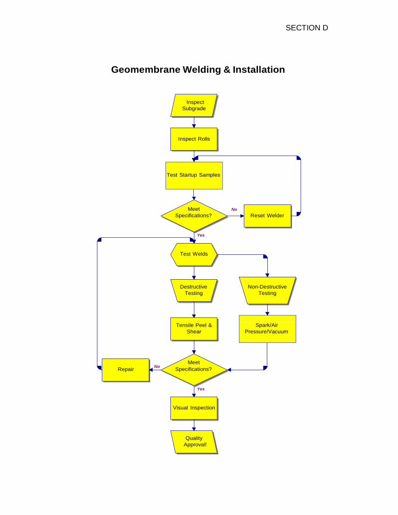
Spark/Air
Pressure/Vacuum
Geomembrane Welding & Installation
Inspect
Subgrade
Inspect Rolls
Test Startup Samples
Meet
Specifications?
No
Reset Welder
Yes
Test Welds
Destructive
Testing
Non-Destructive
Testing
Tensile Peel &
Shear
Repair
Meet No
Specifications?
Yes
Visual Inspection
Quality
Approval!

SECTION E
MATERIAL SPECIFICATIONS AND MANUFACTURING QUALITY CONTROL REQUIREMENTS
This section contains Rowad Geo, standard material specification sheets. These sheets include minimum physical property requirements and manufacturing quality control testing frequencies. Which can be down load from our website?
Rowad’s manufacturing division will provide material meeting the following requirements unless superseded by site-specific project requirements (see Section G)

SECTION F
INSTALLATION QUALITY CONTROL AND QUALITY ASSURANCE REQUIREMENTS
This section contains Rowad Geo, standard values for seam quality and non-destructive testing parameters Rowad’s Construction Division will install material as per the following requirements unless superseded by site-specific project requirements (see Section G). Air Pressure Testing
• Nondestructive air pressure testing of fusion welded seams shall conform to the following parameters:
Maximum Acceptable Pressure and Pressure Loss
HDPE
LLDPE
Thickness
Max. Pressure
Allowable Loss
Max. Pressure
Allowable Loss
20-mil
20 psi
5 psi
20 psi
5 psi
30-mil
25 psi
5 psi
25 psi
5 psi
40-mil
30 psi
4 psi
30 psi
4 psi
60-mil
30 psi
3 psi
30 psi
3 psi
80-mil
35 psi
2 psi
35 psi
2 psi
100-mil
35 psi
2 psi
35 psi
2 psi
Destructive Testing
• Destructive test samples shall be taken nominally every 500 feet of seam.
• The destructive sample shall be 12” wide by 48” long with the seam centered lengthwise. The sample shall be cut into four (4) parts for Rowad’s on-site archives, the Owner’s archives, the CQA laboratory for testing, and field testing.
• Five specimens shall be tested for shear strength and five for peel adhesion. 4 out of 5 specimens must meet the following minimum requirements to be considered “passing”.
HDPE Minimum Acceptable Strength (lbs / in. width)
Thickness
Shear Strength Peel Adhesion Strength
Wedge Weld Extrusion Weld
40-mil 80 52 45
60-mil 120 78 72
80-mil 160 104 90
100-mil 200 130 120
LLDPE Minimum Acceptable Strength (lbs / in. width)
Thickness
Shear Strength Peel Adhesion Strength
Wedge Weld Extrusion Weld
40-mil 44 40 40
60-mil 66 60 60
80-mil 88 75 70
100-mil 110 94 88

SECTION G
SITE-SPECIFIC REQUIREMENTS
This section contains site-specific project requirements including material specifications, seam quality criteria and non-destructive testing and welding parameters.
These requirements supersede Rowad Geo, standard requirements found in Section E and Section F.