method of statement for - abcos industrial
TRANSCRIPT
METHOD OF STATEMENT
FOR
FACTORY ACCEPTANCE TEST PROCEDURE
OF
LOW VOLTAGE SWITCHBOARDS
Page 1 of 13

CONTENTS
S/NO. DESCRIPTION
1.0 Scope of Work
2.0 Safety & Risk Control
3.0 Appendix : Typical Test Forms
Page 2 of 13
Scope of Work
1.1 Purpose
The aim of this documentation is to outline the FAT procedure of Low
Voltage Main Switchboard.
A) Visual Inspection Test
B) Insulation Test
C) High Voltage Injection Test
D) Primary Current Injection Test
E) Metering Current Transformer Polarity Test
F) Secondary Current Injection Test
1.2 Working Location
Approved LV main switchboard to be used for the FAT. FAT is conducted
at Sunlight factory, Singapore.
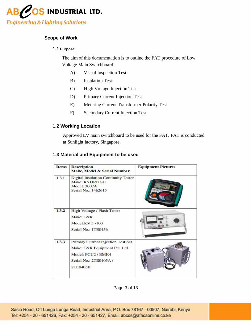
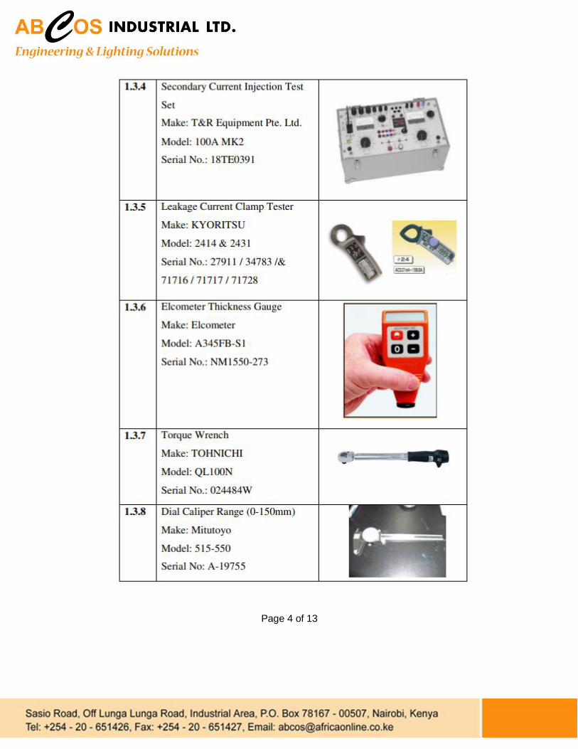
1.3 Material and Equipment to be used
Page 3 of 13
Page 4 of 13
1.4 FAT procedure
(A) Visual Inspection Test
1.4.1 Visual inspection with customer will be carried out on the LV
switchboard to
a. Check the layout of fitted components
b. Check the over all dimension of switchboard, size of busbars, cables
and earthing conductors and location of feeder entry point.
c. Check and verify the brand, model, and circuit identification of
components installed such as breakers, current transformers, fuses,
ammeters, voltmeters, power meters and protection relays etc.
d. Check overall paint work, door locking device, door gasket, door
hinges, door cut-out holes
e. Check the busbar and cable tightening, the marking, busbar
clearance, base angle bar and plinth
f. Check the labels, name plate and phase identification
(B) Insulation Test
1.4.2 Carry out 500V meggar test for phase to earth, neutral to earth, phase to
neutral and phase to phase to measure the insulation resistance with all
breakers in ‘ON’ positions.
(C) High Voltage Injection Test
1.4.3 Carry out 500V meggar test between each stressed phase and all other
phase connected to exposed conductive parts with all breakers in ‘ON’
positions.
1.4.4 Apply 2.5kV AC voltage between each stressed phase and all other phase
connected to exposed conductive parts for 60 seconds and measure the
leakage current.
. Page 5 of 13
(D) Primary Current Injection Test
1.4.6 Temporarily short the R, Y, B & N primary bars on one side of the
protection current transformers.
1.4.7 Connect the primary injection test set on R-phase and N on primary bars
on the other side of the current transformers.
1.4.8 Connect an ammeter to the R-phase of CT to monitor the secondary
current.
1.4.9 Connect a milli-ammeter to the earth-fault relay current coil to monitor
the spill current.
1.4.10 Inject 50% and 100% of the CT ratio through the primary bars and record
spill current respectively. At the same time, record the secondary current
of the R-phase respectively.
1.4.11 Repeat test mentioned from 1.4.7 to 1.4.10 with Y-phase and B-phase.
Page 6 of 13
(E) Secondary Current Injection Test
1.4.12 Select the current plug setting of IDMTL relay to the rated current of 5A
and TMS of 0.1 for 3/10 characteristic.
1.4.13 Inject secondary current of 5A to R-phase and adjust pickup current to 5A.
1.4.14 Inject 10A, 15A and 25A to R-phase and record the tripping time
respectively. The time should fall with +30% and -10% of the standard
timing.
1.4.15 Select the proposed current setting and adjust the pickup current
accordingly.
1.4.16 Repeat the test from 1.4.13 to 1.4.15 with Y-phase and B-phase.
(F) Metering Current Transformer Polarity Test
1.4.17 Temporarily short the R, Y, B & N primary bars on one side of the
protection current transformers.
1.4.18 Connect the primary injection test set on R-phase and Y-phase on primary
bars on the other side of the metering current transformers.
1.4.19 Connect an ammeter to the R-phase of CT to monitor the secondary
current.
1.4.20 Connect a milli-ammeter to earth cable to monitor the spill current. 1.4.21 Inject 50% and 100% of the CT ratio through the primary bars and record
the spill current respectively. Same time to record the secondary current
of the R-phase.
1.4.22 Repeat test mentioned from 1.4.18 to 1.4.21 with Y-phase by connecting
the primary injection test set on Y-phase and B-phase
1.4.23 Repeat test mentioned from 1.4.18 to 1.4.21 with B-phase by connecting
the primary injection test set on B-phase and R-phase
Page 7 of 13
2. Safety & Risk Control
2.1 Safety Arrangement
To control the risks during the FAT, the following arrangement will be done
(A) Safety barriers will be installed surrounding the area where the FAT is going
to be carried out.
(B) Danger signs will be hanged to warn the people who approach the FAT area
(C) RED colour warning lamp will be made to be flashing during supplying
power to the board for testing
(D) Fire extinguisher will be placed for emergency usage at FAT area
(E) A First aid box will be placed at FAT area for emergency purpose
Page 8 of 13

4. Appendix : Test Circuits (A) Test Circuit of Insulation Test (Meggar)
Incoming
R Y B NE
IR
Meggar
(500VDC)
IR
PHASE – EARTH PHASE – NEUTRAL PHASE - PHASE
Meggar Test On Low-Voltage
System without Grounding
R Y B N
Outgoing
Page 9 of 13

(B) Test Circuit of High Voltage Injection Test
Incoming
R Y B N E
IR
High Voltage
Injection Test (2.5 KVAC for 1min)
IR - Ie mA Leakage Current
Shorting
Ie Earth
Link
High Voltage Injection Test
On Low-Voltage System
without Grounding
R Y B N
Outgoing
Page 10 of 13
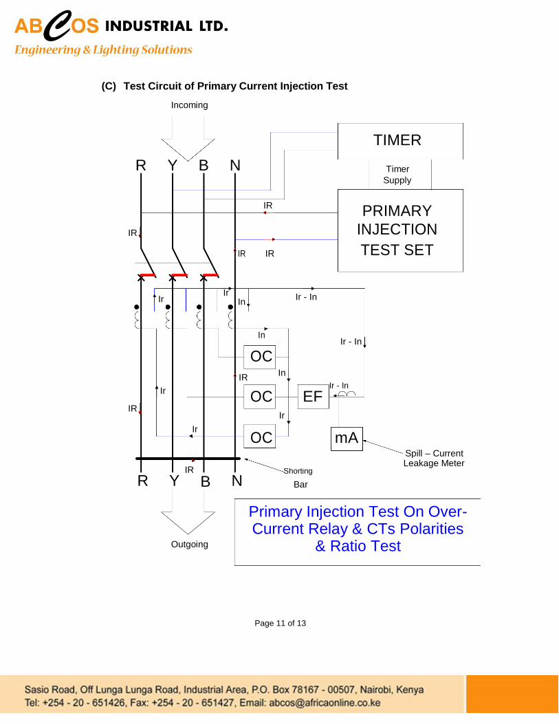
(C) Test Circuit of Primary Current Injection Test
Incoming
TIMER
R Y B N Timer
Supply
IR PRIMARY
IR INJECTION
IR IR TEST SET
Ir
Ir Ir - In In
In Ir - In
OC
IR In
Ir
Ir - In OC EF
IR Ir
Ir OC mA
Spill – Current
IR Leakage Meter
R Y N Shorting
B Bar
Outgoing
Primary Injection Test On Over-Current Relay & CTs Polarities
& Ratio Test
Page 11 of 13

(C) Test Circuit of Secondary Current Injection Test
Page 12 of 13

(D) Test Circuit of Metering Current Transformer Polarity & Ratio Test
Page 13 of 13