method for fabricating a reinforced wide shallow concrete...
TRANSCRIPT

Method for fabricating a reinforced wide shallow concrete beam with increased shear resistance efficiency
Authors Ahmed B Shuraim
Publication date 2013/12/3
Patent office US
Patent number 8595937
Application number
13/110,396
Pages 93-112
Description A method for fabricating a reinforced concrete beam which greatly increases the effectiveness of stirrups in contributing to shear resistance. The method for fabricating a reinforced concrete beam generally includes the steps of positioning a plurality of rebars parallel with respect to each other to form the internal reinforced frame of the beam. A plurality of stirrups may then be extended around the plurality of rebars to provide additional support. An equivalent spacing value is computed in terms of transverse spacing (sw), ...
Scholar articles Method for fabricating a reinforced wide shallow concrete beam with increased shear resistance efficiency
AB Shuraim - US Patent 8,595,937, 2013
Related articles - All 4 versions

US008595937B2
(12) United States Patent (10) Patent N6.= US 8,595,937 B2 (45) Date of Patent: Dec. 3, 2013 Shuraim
(54) METHOD FOR FABRICATINGA g; * 54mins er al. 267/166
REINFORCED WIDE SHALLOW CONCRETE , a e M10011 BEAM WITH INCREASED SHEAR 7,529,650 B2 * 5/2009 Wakelam et a1. .. RESISTANCE EFFICIENCY
8,196,368 B2* 6/2012 Sarraf 2007/0039276 A1 2/ 2007 Sorensen
(76) Inventor: Ahmed B. Shuraim, Riyadh (SA) * Cited by examiner
( * ) Notice: Subject to any disclaimer, the term of this Primary Examiner * Richard Chang _ patent is extended or adjusted under 35 (74) Attorney, Agent, or Fzrm * Jason L. G1lbert
U.S.C. 154(b) by 434 days. ABSTRACT (57)
(21) Appl. No.: 13/110,396 A method for fabricating a reinforced concrete beam Which greatly increases the effectiveness of stirrups in contributing
May 18-1 2011 to shear resistance. The method for fabricating a reinforced concrete beam generally includes the steps of positioning a
(22) Filed:
(65) Prior Publication Data plurality of rebars parallel With respect to each other to form
US 2012/0291286 Al the internal reinforced frame of the beam. A plurality of Nov. 22, 2012 stirrups may then be extended around the plurality of rebars to provide additional support. An equivalent spacing value is (51) Int. C1.
(200601) computed in terms of transverse spacing (sW), longitudinal spacing (sL) and effective depth (d) and ef?ciency is then maximized in light of practical considerations by varying the
B21D 49/00
(52) us. C1. USPC 29/897.34; 29/897; 29/8973; 29/897.33; _ _
29/897_35 transverse spac1ng (sW), In a preferred embodlment, after calculating the longitudinal spacing (sL) of the stirrups and 58 FM fCl '? t' S h
( ) 1e 0 assl ca Ion earc the effective depth (d) of the rebars, the stirrups are positioned USPC 29/897, 897.3, 897.33, 897.34, 897.35
Within the rebars using a transverse spacing (sW) calculated by the folloWing equation:
See application ?le for complete search history.
(56) References Cited
U.S. PATENT DOCUMENTS
11/1966 Gersovitz 8/1978 Dave
3,283,458 A 4,105,739 A 4,573,013 A * 2/1986 Kusenbergeret a1. 324/238 4,702,052 A * 10/1987 Chow 52/2232 15 Claims,7DraWing Sheets

US. Patent Dec. 3, 2013 Sheet 1 of7 US 8,595,937 B2
FIG. 1

US. Patent Dec. 3, 2013 Sheet 2 of7 US 8,595,937 B2
FIG. 2

US. Patent Dec. 3, 2013 Sheet 3 of7 US 8,595,937 B2
w J é; S
:11 [221 E3 E3
:3 w r:
20 12
FIG. 3

US. Patent Dec. 3, 2013 Sheet 4 of7 US 8,595,937 B2

US. Patent Dec. 3, 2013 Sheet 5 017 US 8,595,937 B2
Casting f'c fyv Sw Av d 5L Avd Total Group MPa MPa STIRRUP CONFIGURATION mm mm2 mm mm 5L |oad,kN
29483 - -152- - 474
29 483 660 157 152 80 300 644
1
29 483 440 157 152 80 300 647
29 483 230 157 152 80 300 677
28 - - 149 - - 470
28 465 660 201 149 75 400 471
11 28 465 230 201 149 75 400 642
28 465 230 201 149 75 400 800
28 465 230 201 149 100 300 782
28 465 230 201 149 125 240 703
30 - - 149 - - 464
30 465 660 201 149 75 400 701
111
30 465 230 201 149 75 400 703
30 465 230 201 149 75 400 893
30 465 |[ Z |[ I j] I ]| 230 201 149 100 300 812 30 465 230 201 149 125 240 702
FIG. 7
US. Patent Dec. 3, 2013 Sheet 6 of7 US 8,595,937 B2
i i i i i i i i i i
i i i i E H 2100.54.20 1 0000
Longitudinal Spacing Ratio, SL/d
FIG. 8

US. Patent Dec. 3, 2013 Sheet 7 of7 US 8,595,937 B2
iii \SL/Seq
_
0 0 3 7._ 0 0
0.0000 Transverse Spacing Ratio, Sw/d
FIG. 9

US 8,595,937 B2 1
METHOD FOR FABRICATING A REINFORCED WIDE SHALLOW CONCRETE
BEAM WITH INCREASED SHEAR RESISTANCE EFFICIENCY
CROSS REFERENCE TO RELATED APPLICATIONS
Not applicable to this application.
STATEMENT REGARDING FEDERALLY SPONSORED RESEARCH OR DEVELOPMENT
Not applicable to this application.
BACKGROUND OF THE INVENTION
1. Field of the Invention The present invention relates generally to the construction
of reinforced concrete beams and more speci?cally it relates to a method for fabricating a reinforced Wide shalloW con crete beam With increased shear resistance ef?ciency Which greatly increases the effectiveness of stirrups in contributing to shear resistance.
2. Description of the Related Art Any discussion of the related art throughout the speci?ca
tion should in no Way be considered as an admission that such related art is Widely knoWn or forms part of common general knowledge in the ?eld.
Reinforced concrete beams have been in use for years in building constructions. Wide beams in concrete buildings are generally constructed to be hidden by designing the Wide beams to have the same depth as the supported ?oor (i.e. in a joist construction). Such Wide shalloW beams are generally supported on elongated columns in constructions of residen tial buildings.
In the past, shear strength in reinforced concrete beams, or V”, has been calculated as the summation of contributions of concrete and stirrups as shoWn in the beloW equation:
VnIVC+ VSL.
The ?rst parameter, V6, is the concrete contribution to shear strength and is generally expressed by empirical equations involving a number of in?uencing parameters. For Wide beams, support Width has also been considered as an addi tional parameter Which causes geometric differences and induces disturbed force How.
The second parameter, VSL, is the stirrup contribution to shear strength and has previously been formulated for vertical stirrups as:
sL :
Where, sL is the longitudinal spacing of stirrups, Av is the vertical legs area, d is the effective depth and fyv is the yield strength of stirrups. HoWever, this equation does not include a direct parameter for the transverse spacing of stirrup legs. Building codes in various countries appear to differ in their treatment of the transverse spacing issue. For example, Euro code 2 suggests spacing limits of 0.75 d or 600 mm in both the Width and longitudinal direction. In contrast, ACI3l8-08, Which Was released by the American Concrete Institute, sug gests spacing limits of 0.5 d in the longitudinal direction, but does not provide a limit on the leg spacing in the transverse direction.
20
25
30
35
40
45
50
55
60
65
2 While there have been numerous studies conducted on the
issue, a consensus has yet to be reached regarding the issue of transverse spacing requirements With respect to Wide shalloW beams. Because of the inherent problems With the related art, there is a need for a neW and improved method for fabricating a reinforced Wide shalloW concrete beam Which utiliZes neW guidelines for computing stirrup contribution to shear strength to ensure adequate safety of Wide shalloW members for one-Way shear.
BRIEF SUMMARY OF THE INVENTION
A method Which utiliZes neW guidelines for computing stirrup contribution to shear strength to ensure adequate safety of Wide shalloW members for one-Way shear. The method pertains to computing and improving the shear stirrup contribution through a con?guration ef?ciency factor (7») that is related to the form and spacing of the stirrups. The e?i ciency factor (7») is integrated into the main design equation to ensure safety and ef?ciency such as:
The invention generally relates to a method for fabricating a reinforced Wide shalloW concrete beam Which comprises the steps of positioning a plurality of rebars parallel With respect to each other to form the internal reinforced frame of the beam. A plurality of stirrups may then be extended either Wholly or partially around the plurality of rebars to provide additional support. Each rebar Will generally include a plu rality of vertically-extending legs. The transverse spacing (sW) of each leg With respect to the other legs is preferably set to be less than or equal to a maximum value (sW ), calculated as a function of the longitudinal spacing (s L) 8f the stirrups and the effective depth (d) of the beam 20 by the folloWing equation, Which maximiZes shear strength ef?ciency:
Concrete may then be poured around the rebars, stirrups and legs to complete the Wide shalloW concrete beam.
For situations Where the transverse spacing (sW) is not complying With the required maximum value (sW ) sug gested by the above equation (as might happen for p?ifactical considerations or in assessing an existing condition), the invention provides the means to assess the actual ef?ciency factor (7») that needs to be considered in the shear calculation.
For computing the ef?ciency factor (7») for a particular closed con?guration, an equivalent spacing (seq) must be computed as
5L 0.25 Seq VSLSW 25L
Based on the equivalent spacing (seq) and the longitudinal spacing (s L), the ef?ciency factor (7») is computed as
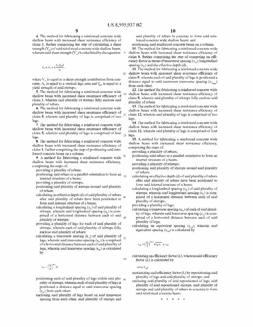
It should be noted that the ef?ciency factor (7») can be obtained graphically from FIG. 9 Without the need to use the above equations.
There has thus been outlined, rather broadly, some of the features of the invention in order that the detailed description thereof may be better understood, and in order that the present

US 8,595,937 B2 3
contribution to the art may be better appreciated. There are additional features of the invention that Will be described hereinafter and that Will form the subject matter of the claims appended hereto. In this respect, before explaining at least one embodiment of the invention in detail, it is to be under stood that the invention is not limited in its application to the details of construction or to the arrangements of the compo nents set forth in the following description or illustrated in the draWings. The invention is capable of other embodiments and of being practiced and carried out in various Ways. Also, it is to be understood that the phraseology and terminology employed herein are for the purpose of the description and should not be regarded as limiting.
BRIEF DESCRIPTION OF THE DRAWINGS
Various other objects, features and attendant advantages of the present invention Will become fully appreciated as the same becomes better understood When considered in con junction With the accompanying draWings, in Which like ref erence characters designate the same or similar parts through out the several vieWs, and Wherein:
FIG. 1 is an upper perspective vieW of a Wide shalloW beam positioned on a column.
FIG. 2 is an upper perspective vieW of the interior of a Wide shalloW beam Which shoWs positioning of rebars and stirrups.
FIG. 3 is a top vieW of a construction using Wide shalloW beams, columns and joists.
FIG. 4 is a front cutaWay vieW of a multiple-leg closed stirrup con?guration.
FIG. 5 is a front cutaWay vieW of a tWo-leg closed stirrup con?guration.
FIG. 6 is a front cutaWay vieW of an open stirrup con?gu ration Which is not el?cient in resisting shear.
FIG. 7 is a table illustrating data collected from various stirrup con?gurations.
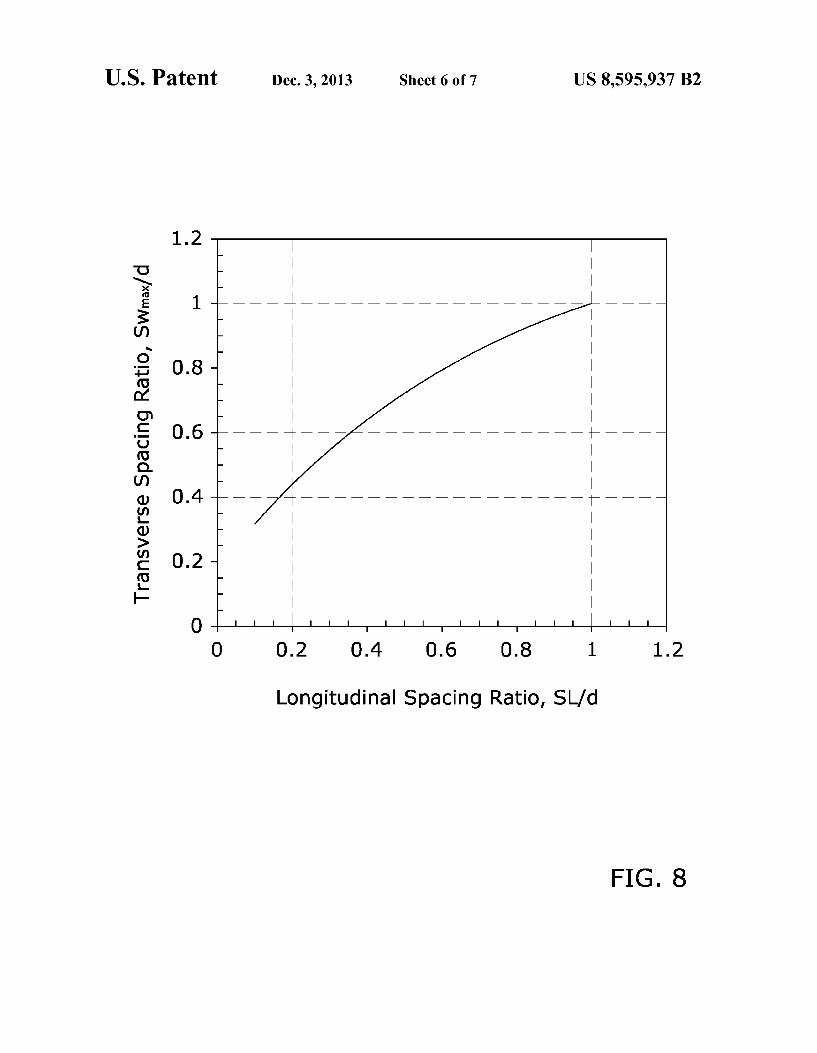
FIG. 8 is a graph illustrating the relationship betWeen the maximum transverse spacing ratio and longitudinal spacing ratio to maximize ef?ciency.
FIG. 9 is a graph illustrating the comparison betWeen stir rup ef?ciency in resisting shear force and the transverse spac ing ratio.
DETAILED DESCRIPTION OF THE INVENTION
A. OvervieW.
Turning noW descriptively to the draWings, in Which simi lar reference characters denote similar elements throughout the several vieWs, FIGS. 1 through 8 illustrate a method for fabricating a reinforced Wide shalloW concrete beam 20, Which comprises the steps of positioning a plurality of rebars 24 parallel With respect to each other to form the internal reinforced frame of the beam 20. A plurality of stirrups 22 may then be extended either Wholly or partially around the plurality of rebars 24 to provide additional support. Each rebar 24 Will generally include a plurality of vertically-ex tending legs 26. The transverse spacing (sW) of each leg 26 With respect to the other legs 26 is preferably set to be less than or equal to a maximum value (sW ), calculated as a function of the longitudinal spacing (s L) 0”?‘ the stirrups 22 and the effective depth (d) of the beam 20 by the folloWing equa tion, Which maximiZes shear strength ef?ciency:
20
25
30
35
40
45
50
55
60
65
Swmax : (ijwosd
Concrete may thenbe poured around the rebars 24, stirrups 22 and legs 26 to complete the Wide shalloW concrete beam 20.
For situations Where the transverse spacing (sW) is not complying With the required maximum value (sW ) sug gested by the above equation (as might happen for p?ifactical considerations or in assessing an existing condition), the invention provides the means to assess the actual ef?ciency factor (7») that needs to be considered in the shear calculation.
For computing the ef?ciency factor (7») for a particular closed con?guration, an equivalent spacing (seq) must be computed as
5L 0.25 seq = m 2 5L
Based on the equivalent spacing (seq) and the longitudinal spacing (s L), the ef?ciency factor (7») is computed as
It should be noted that the ef?ciency factor (7») can be obtained graphically from FIG. 9 Without the need to use the above equations. The ef?ciency factor (7») is integrated into the main design
equation to ensure safety and ef?ciency such as:
B. Reinforced Wide ShalloW Concrete Beams. The present invention is directed toWard a method of fab
ricating reinforced Wide shalloW concrete beams With increased shear resistance ef?ciency 20. FIG. 1 is an upper perspective vieW of an exemplary Wide shalloW beam 20 positioned on a narroW column 12 as is standard in many current construction projects. HoWever, it is appreciated that the methods described herein should not be construed as being limited to the fabrication of the speci?c design, shape or siZe of Wide shalloW beam 20 shoWn in the ?gures.
Reinforced Wide shalloW concrete beams 20 are generally comprised of beams of concrete Which include reinforced bars (rebars) 24 incorporated Within the concrete itself to strengthen the concrete in tension. Each rebar 24 is generally comprised of an elongated rod comprised of steel or other high durability materials. As shoWn in FIG. 2, a plurality of rebars 24 Will generally extend horiZontally through the Wide shalloW concrete beam 20.
Reinforced Wide shalloW concrete beams 20 may also include a plurality of stirrups 22 in some con?gurations. Stirrups 22 are generally comprised of rods of steel or other high durability materials Which extend either partially or fully around the plurality of rebars 24 to provide additional tension support. Generally, stirrups 22 Will include one or more legs 26 Which extend perpendicularly With respect to the horizon tally-extending stirrups 22. Wide shalloW reinforced concrete beams 20 are generally
utiliZed in constructions in combination With joists 14 and columns 12.As shoWn in FIG. 3, an exemplary construction is comprised of Wide shalloW reinforced concrete beams 20 Which are positioned horiZontally and supported by vertical columns 12. Joists 14 extend perpendicularly With respect to the beams 20 to complete the constructions.
Reinforced Wide shalloW concrete beams 20 may vary in their constructions based on the number, spacing and place

US 8,595,937 B2 5
ment of stirrups 22 and legs 26. FIG. 4 illustrates a common closed stirrup 22 con?guration in Which the stirrup 22 fully encloses the horizontally extending rebars 24. This ?gure also illustrates a four-leg con?guration Which utiliZes four verti cally extending legs 26 positioned at various locations on the stirrups 22. FIG. 5 illustrates an exemplary closed stirrup 22 con?guration Which utiliZes tWo vertically extending legs 26.
Reinforced concrete beams 20 may also be constructed With an open con?guration as shoWn in FIG. 6. In such a con?guration, the stirrups 22 do not completely enclose the rebars 24, but instead simply Wrap around rebars 24 at various locations. The con?guration shoWn in FIG. 6 is commonly referred to as a four-leg open stirrup 22 con?guration. Test data by the inventor has shoWn that such open con?gurations are not ef?cient in resisting shear and should thus be avoided. The method described in the present application are directed toWard calculating the most e?icient and shear-resistant con ?guration and spacing for any given construction project. C. Calculation of Spacing and Ef?ciency Factor.
While pre-existing methods of determining proper spacing of stirrups 22 solely utiliZe longitudinal spacing in their cal culations, the methods claimed in the present application utiliZe a neW equivalent spacing value denoted by the symbol seq. This neW equivalent spacing value is a function of both transverse spacing (sW) and longitudinal spacing (sL) of stir rups in combination With the effective depth (d) of the beam 20.
Through testing and analysis, the inventor of the present invention has calculated the equivalent spacing as shoWn in the beloW equation:
5L 0.25 seq : VsLsW 2 5L
Where the longitudinal spacing (s L) is comprised of the hori Zontal distance betWeen each separate stirrup 22 in a beam 20 and the transverse spacing (sW) is comprised of the horiZontal distance betWeen each vertically-extending leg 26 of a stirrup 22. If the equivalent spacing (seq) is calculated as being less than the longitudinal spacing (s L), than the longitudinal spac ing (s L) should be utiliZed for the value of the equivalent spacing (Seq). By utiliZing the inventor’s proposed equivalent spacing
value (seq), more e?icient calculations may be made to deter mine proper stirrup 22 spacing Which account for both trans verse spacing and longitudinal spacing.
Based on the equivalent spacing (seq) and the longitudinal spacing (s L), the ef?ciency factor (7») is computed as
AISL/SEq. It should be noted that the ef?ciency factor (7») can be obtained graphically from FIG. 9 Without the need to use the above equations.
The ef?ciency factor (7») is integrated into the main design equation to ensure safety and ef?ciency such as:
To determine proper spacing, a maximum limit on the transverse spacing betWeen consecutive legs 26 in a stirrup 22 cross-section is determined. The inventor has determined that the most ef?cient calculation of transverse spacing limita tions is calculated by the beloW equation, Which leads to an ef?ciency factor (7P1):
20
25
30
35
40
45
50
55
60
65
Swmax : (ijwosd
This equation may be utiliZed With neW Wide shalloW con crete beam 20 constructions to maximiZe e?iciency of stirrup 22 spacing in contributing to shear strength.
FIG. 8 is a graph illustrating the relationship betWeen maximum transverse spacing ratio and longitudinal spacing ratio to maximiZe e?iciency. FIG. 9 is a graph illustrating the comparison betWeen stirrup 22 ef?ciency in resisting shear force and the transverse spacing ratio. D. Test Data. The inventor of the present application conducted a num
ber of tests to con?rm that the above equations may be utiliZed to maximiZe shear strength in concrete beam 20 construc tions. FIG. 7 illustrates test results for a number of con?gu rations to illustrate the application of the principles claimed in the present application. The test data Was compiled by utiliZing sixteen specimens
of Wide shalloW reinforced concrete beams 20. The speci mens Were composed of three groups (I, II, III) based on casting time. The beams 20 in Group I Were tested betWeen 35 and 42 days from the time of casting and the beams 20 in Groups II and III Were tested betWeen 120 and 180 days from the time of casting.
Various stirrup 22 con?gurations Were tested. Each of the con?gurations are illustrated by a sectional front vieW Within the table of FIG. 7. Testing stirrup 22 con?gurations include beams 20 Without stirrups 22, tWo-leg closed stirrup 22 con ?gurations, tWo-leg open stirrup 22 con?gurations, four-leg closed stirrup 22 con?gurations and four-leg open stirrup 22 con?gurations. Loads Were applied to each specimen over full-Width plates located at the center of each span. Each specimen Was loaded With several load increments up to failure using a displacement control scheme. The results of the test data shoWed that beams Without
stirrups 22 produced consistent concrete shear strength. A comparison With Well-known codes and regression equations shoWed that the concrete shear strength of such no-stirrup 22 con?gurations Was mostly predicted conservatively. Beams 20 With constant amount of stirrups 22 shoWed clearly that stirrups 22 arranged in four-leg closed con?gurations Were signi?cantly more effective than stirrups 22 arranged in tWo leg closed con?gurations. Beams 20 With four-leg stirrups 22 shoWed signi?cant and consistent improvement in the contri bution of stirrups 22 for shear resistance even When a less area of stirrups 22 Was used. The test results made clear that Wide shalloW beams 20 Which are reinforced With tWo-leg stirrups 22 are susceptible to come shear de?cient When shear strength Was calculated Without accounting for transverse spacing, as has been common in the prior art. Thus, the equivalent spacing calculations Were shoWn to greatly improve stirrup 22 contribution and con?rmed that the inven tor’s transverse spacing limit calculations may be used in order to fully utiliZe stirrups 22 effectively. E. Method of Fabrication.
In use, the above concepts may be utiliZed to construct more Wide shalloW concrete beams 20 With improved shear strength and ef?ciency. First, rebars 24 are provided and positioned to form the internal reinforcement structure of the Wide shalloW concrete beam 20. Preferably closed stirrups 22 are then positioned around the rebars 24 as shoWn in FIG. 2, With the longitudinal spacing (s L) of the stirrups 22 and the effective depth (d) of the beam 20 being measured. Test data has shoWn that closed stirrups 22 are preferable for maximiZ

US 8,595,937 B2 7
ing shear resistance. The proper transverse spacing (sW) of any legs 26 utilized may then be chosen With the maximum limit (swm) calculated from the below equation:
swmax : (Sifmd.
After a value is determined for the proper transverse spac ing (sW), legs 26 may be added, Wherein each leg 26 is a distance equal to sW aWay from the other legs 26. Concrete may then be poured around the rebars 24, stirrups 22 and legs 26 to complete the Wide shalloW concrete beam 20.
For situations Where the transverse spacing (sW) is not complying With the required maximum value (sW ) sug gested by the above equation (as might happen for p?ifactical considerations or in assessing an existing condition), the invention provides the means to assess the actual e?iciency factor (7») that needs to be considered in the shear calculation.
For computing the e?iciency factor (7») for a particular closed con?guration, an equivalent spacing (seq) must be computed as
5L 0.25 Seq = VSLSW 2 SL.
Based on the equivalent spacing (seq) and the longitudinal spacing (s L), the ef?ciency factor (7») is computed as
It should be noted that the ef?ciency factor (7») can be obtained graphically from FIG. 9 Without the need to use the above equations.
The ef?ciency factor (7») is integrated into the main design equation to ensure safety and ef?ciency such as:
The ?rst parameter, V6, is the concrete contribution to shear strength and is generally expressed by empirical equations involving a number of in?uencing parameters. For Wide beams, support Width has also been considered as an addi tional parameter Which causes geometric differences and induces disturbed force How.
The second parameter, VSL, is the stirrup contribution to shear strength and has previously been formulated for vertical stirrups as:
sL :
Where, sL is the longitudinal spacing of stirrups, Av is the vertical legs area, d is the effective depth and fyv is the yield strength of stirrups.
Unless otherWise de?ned, all technical and scienti?c terms used herein have the same meaning as commonly understood by one of ordinary skill in the art to Which this invention belongs. Although methods and materials similar to or equivalent to those described herein can be used in the prac tice or testing of the present invention, suitable methods and materials are described above. All publications, patent appli cations, patents, and other references mentioned herein are incorporated by reference in their entirety to the extent alloWed by applicable laW and regulations. In case of con?ict, the present speci?cation, including de?nitions, Will control.
20
25
30
35
40
50
55
65
8 The present invention may be embodied in other speci?c forms Without departing from the spirit or essential attributes thereof, and it is therefore desired that the present embodi ment be considered in all respects as illustrative and not restrictive. Any headings utiliZed Within the description are for convenience only and have no legal or limiting effect.
The invention claimed is: 1. A method for fabricating a reinforced concrete Wide
shalloW beam With increased shear resistance e?iciency, comprising the steps of:
providing a plurality of rebars; positioning said rebars in a parallel orientation to form an
internal structure of a beam; providing a plurality of stirrups; positioning said plurality of stirrups around said plurality
of rebars; calculating an effective depth (d) of said plurality of rebars
after said plurality of rebars have been positioned to form said internal structure of a beam;
calculating a longitudinal spacing (sL) of said plurality of stirrups, Wherein said longitudinal spacing (sL) is com prised of a horiZontal distance betWeen each of said plurality of stirrups;
providing a plurality of legs; determining a practical value for a transverse spacing (sW)
of said plurality of legs, Wherein said transverse spacing (sW) is comprised of a horiZontal distance betWeen each of said plurality of legs;
calculating an equivalent spacing (seq), Wherein said equivalent spacing (seq) is calculated by
calculating an ef?ciency factor (7»), Wherein said e?iciency factor (7») is calculated by
maximizing said ef?ciency factor (7») by repositioning said plurality of legs and said plurality of stirrups; and
enclosing said plurality of said repositioned of legs, said plurality of said repositioned stirrups and said plurality of rebars in concrete to form said reinforced concrete beam.
2. The method for fabricating a reinforced concrete Wide shalloW beam With increased shear resistance ef?ciency of claim 1, calculating a maximum transverse spacing (sW ) of said plurality of legs, Wherein said maximum transversenszpac ing (swm) is calculated by
Swmax : (ijwosd;
and positioning each of said plurality of legs Within said plu
rality of stirrups, Wherein each of said plurality of legs is positioned a distance less than or equal to saidmaximum transverse spacing (sW ) from each other.
3. The method for fabricnanting a reinforced concrete Wide shalloW beam With increased shear resistance ef?ciency of claim 1, Wherein each of said plurality of legs is positioned a distance equal to said maximum transverse spacing (sW ) from each other. m
US 8,595,937 B2
4. The method for fabricating a reinforced concrete Wide shallow beam With increased shear resistance e?iciency of claim 1, further comprising the step of calculating a shear strength (Vn) of said reinforced concrete Wide shalloW beam, Wherein said shear strength (V n) is calculated by the equation:
Where V6 is equal to a shear strength contribution from con crete, Av is equal to a vertical legs area and fyv is equal to a yield strength of said stirrups.
5. The method for fabricating a reinforced concrete Wide shalloW beam With increased shear resistance e?iciency of claim 1, Wherein said plurality of stirrups fully enclose said plurality of rebars.
6. The method for fabricating a reinforced concrete Wide shalloW beam With increased shear resistance e?iciency of claim 5, Wherein said plurality of legs is comprised of tWo legs.
7. The method for fabricating a reinforced concrete Wide shalloW beam With increased shear resistance e?iciency of claim 5, Wherein said plurality of legs is comprised of four legs.
8. The method for fabricating a reinforced concrete Wide shalloW beam With increased shear resistance e?iciency of claim 1, further comprising the step of positioning said rein forced concrete beam on a column.
9. A method for fabricating a reinforced concrete Wide shalloW beam With increased shear resistance ef?ciency, comprising the steps of:
providing a plurality of rebars; positioning said rebars in a parallel orientation to form an
internal structure of a beam; providing a plurality of stirrups; positioning said plurality of stirrups around said plurality
of rebars; calculating an effective depth (d) of said plurality of rebars
after said plurality of rebars have been positioned to form said internal structure of a beam;
calculating a longitudinal spacing (sL) of said plurality of stirrups, Wherein said longitudinal spacing (sL) is com prised of a horiZontal distance betWeen each of said plurality of stirrups;
providing a plurality of legs for each of said plurality of stirrups, Wherein each of said plurality of stirrups fully enclose said plurality of rebars;
calculating a transverse spacing (sW) of said plurality of legs, Wherein said transverse spacing (sW) is comprised of a horiZontal distance betWeen each of said plurality of legs, Wherein said transverse spacing (sW) is calculated by
positioning each of said plurality of legs Within said plu rality of stirrups, Wherein each of said plurality of legs is positioned a distance equal to said transverse spacing (sW) from each other;
enclosing said plurality of legs based on said transverse spacing from each other, said plurality of stirrups and
20
25
30
35
40
45
55
60
10 said plurality of rebars in concrete to form said rein forced concrete Wide shalloW beam; and
positioning said reinforced concrete beam on a column. 10. The method for fabricating a reinforced concrete Wide
shalloW beam With increased shear resistance ef?ciency of claim 9, further comprising the step of computing an e?i ciency factor in terms of transverse spacing (sW), longitudinal spacing (s L) and the effective depth (d).
11. The method for fabricating a reinforced concrete Wide shalloW beam With increased shear resistance ef?ciency of claim 9, Wherein each of said plurality of legs is positioned a distance equal to said maximum transverse spacing (sW ) from each other. m
12. The method for fabricating a reinforced concrete Wide shalloW beam With increased shear resistance ef?ciency of claim 9, Wherein said plurality of stirrups fully enclose said plurality of rebars.
13. The method for fabricating a reinforced concrete Wide shalloW beam With increased shear resistance ef?ciency of claim 12, Wherein said plurality of legs is comprised of tWo legs.
14. The method for fabricating a reinforced concrete Wide shalloW beam With increased shear resistance ef?ciency of claim 12, Wherein said plurality of legs is comprised of four legs.
15. A method for fabricating a reinforced concrete Wide shalloW beam With increased shear resistance e?iciency, comprising the steps of:
providing a plurality of rebars; positioning said rebars in a parallel orientation to form an
internal structure of a beam; providing a plurality of stirrups; positioning said plurality of stirrups around said plurality
of rebars; calculating an effective depth (d) of said plurality of rebars
after said plurality of rebars have been positioned to form said internal structure of a beam;
calculating a longitudinal spacing (sL) of said plurality of stirrups, Wherein said longitudinal spacing (sL) is com prised of a horiZontal distance betWeen each of said plurality of stirrups;
providing a plurality of legs; calculating a transverse spacing (sW) of each of said plural
ity of legs, Wherein said transverse spacing (sW) is com prised of a horiZontal distance betWeen each of said plurality of legs;
calculating an equivalent spacing (seq), Wherein said equivalent spacing (seq) is calculated by
calculating an ef?ciency factor (7»), Wherein said e?iciency factor (7») is calculated by
LISL/SEq; maximizing said ef?ciency factor (7») by repositioning said
plurality of legs and said plurality of stirrups; and enclosing said plurality of said repositioned of legs, said
plurality of said repositioned stirrups, said plurality of stirrups and said plurality of rebars in concrete to form said reinforced concrete beam.
* * * * *