method and apparatus for tunneling by melting (patent us 3693731 a)
DESCRIPTION
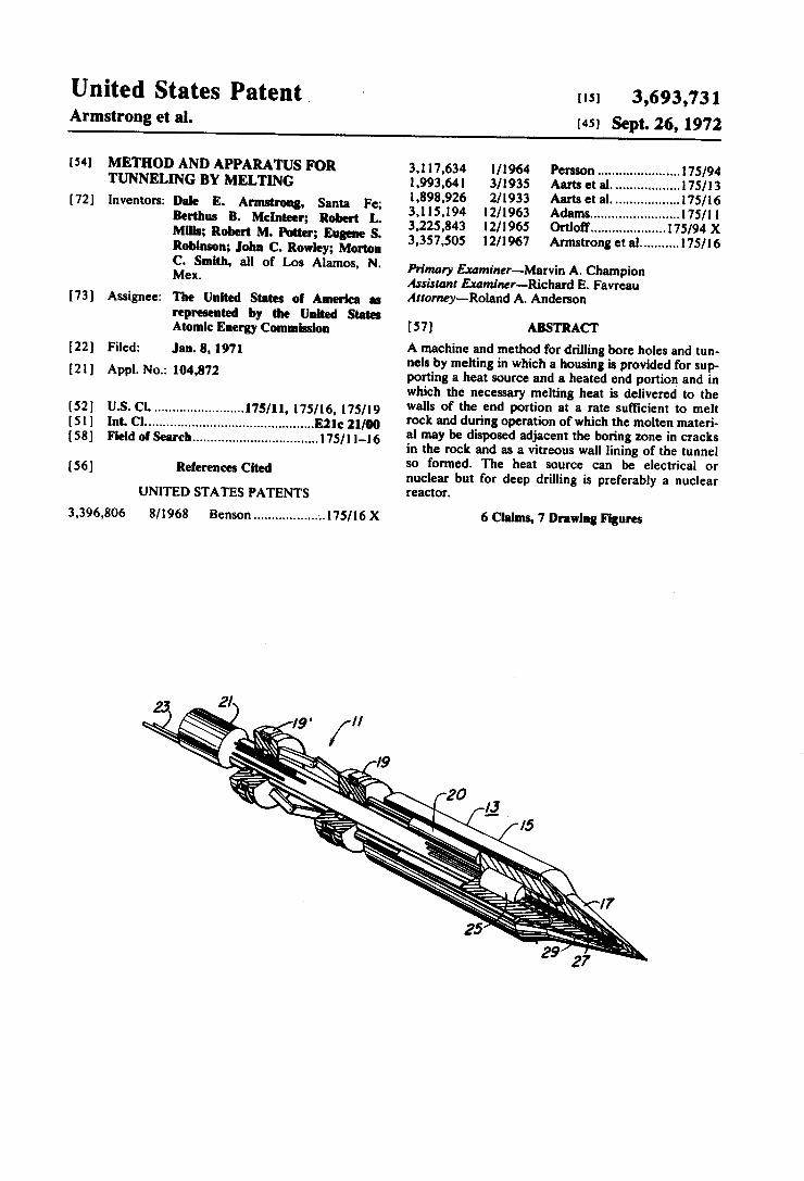
A machine and method for drilling bore holes and tunnels by melting in which a housing is provided for supporting a heat source and a heated end portion and in which the necessary melting heat is delivered to the walls of the end portion at a rate suft'lcient to melt rock and during operation of which the molten material may be disposed adjacent the boring zone in cracks in the rock and as a vitreous wail lining of the tunnel so formed. The heat source can be electrical or nuclear but for deep drilling is preferably a nuclear reactor.TRANSCRIPT
United States Patent Armstrong et al.
[54] METHOD AND APPARATUS FOR TUNNELING BY MELTING
[72] Inventors: Dale E. Armstrong, Santa Fe; Berthus B. Mclnteer; Robert L. Mills; Robert M. Potter; Eugene S. Robinson; John C. Rowley; Morton C. Smith, all of Los Alamos, N. Mex.
[73] Assignee: The United States of America as represented by the United States Atomic Energy Commission
[221 Filed: .Ian.8, 1911
[211 Appl.No.: 104,872
[52] US. Cl. ....................... ..l75/ll, 175/16, 175/19 [5 1] Int. Cl ............................................. ..E2lc 21/00 [58] Field of Search ................................. ..175/ll-l6
[56] References Cited
UNITED STATES PATENTS
3,396,806 8/1968 Benson ................ ..-..175/16 X
us] 3,693,731 [451 Sept. 26, 1972
3,1 17,634 1/1964 Persson ..................... .. 175/94 1,993,641 3/1935 Aarts et al...................175/13 1,898,926 2/1933 Aarts et al. ................ ..l7$/16 3,115,194 12/1963 Adams ....................... ..i75/ll 3,225,843 12/1965 Ortloi’f ................... ..175/94 X 3,357,505 12/ 1967 Armstrong et a1 ......... ..175/16
Primary Examiner-Marvin A. Champion Assistant Examiner-Richard E. Favreau Anomey—Roland A. Anderson
[ 5 7] ABSTRACT
A machine and method for drilling bore holes and tun nels by melting in which a housing is provided for sup porting a heat source and a heated end portion and in which the necessary melting heat is delivered to the walls of the end portion at a rate suft'lcient to melt rock and during operation of which the molten materi al may be disposed adjacent the boring zone in cracks in the rock and as a vitreous wail lining of the tunnel so formed. The heat source can be electrical or nuclear but for deep drilling is preferably a nuclear reactor.
6 Claims, 7 Drawing Figures
PATENTEBSEP‘ZB m2 3.693.731 sum 1 0r 4
Fig. 2 INVENTOR. 00/9 5 Armstrong, Bert/ms B. Mclnfeer,
Robert L.Mi/ls, Robert M Patter, Eugene 5‘. Robinson, John 6‘. Raw/5y
Marion 6‘. Sm! If
WW
PMENTEDSEPZB m
E
3.593.731 SHEET 3 OF 4
\ \\\\\\\\\\
\'\\\\\\\\\\\\\\\\\\\\\\\\\\ \ //// _
7/
65
\ \\ \ \\ \\
\\ \\ I/ 7/ I / I ’
\\\ \ \\ 34
J
45) \ i
\\
\\ \\ \\ \\
\\\ \\ \\‘
WA x 7// //////////////,\ \\ \\\\\\\\\\\\\\\\\\\
56
32
Fig. 4
142451.14
INVENTOR. Dale E Armsfran B.Mc1nf
Robert L. //ls,/?0 . For , Eugene $.Robinsan, Jab .Row/ey,
Morton C. Smith
_, Ber fl;
BY

3,693,731 1
METHOD AND APPARATUS FOR TUNNELING BY MELTING
The invention described herein was made in the course of, or under, a contract with the U. S. ATOMIC ENERGY COMMISSION. It relates generally to a method and apparatus for drilling, tunneling and shaft sinking in rock with particular advantage at hitherto in accessible depths.
This invention'provides a rapid versatile economical method of deep-earth excavation, tunneling and shaft sinking which offers solutions to ecological problems, acquiring natural resources presently inaccessible and access to an enormous reservoir of natural heat energy. These valuable subterranean sources include natural minerals and hydrocarbons, fresh water and clean geothermal heat energy. The accessibility of these resources at the present
time is limited by the technical and economic difficul ties of producing large long holes in the hard rocks of the earth's crust and mantle. The available tools and techniques for relatively shallow drilling, boring, shaft sinking, tunneling and mining in rock are highly developed and in the environments in which they have evolved they are adequately effective and et?cient. However, their efficiencies and feasibility of use decrease rapidly and their ‘costs rise in proportion, as their application is extended to greater depths, harder rocks, and higher rock temperatures and pressures. Among presently available tools for penetrating rock, only the rotary drill appears to be capable of penetrat ing the earth to depths greater than four to ?ve kilome ters at an economically useful rate and at such depths it is limited to producing holes no larger than about one half meter in diameter. It is unlikely that existing methods can be used to explore or excavate the earth to depths greater than about 12 to 15 kilometers. The present invention uses the basic apparatus and
method disclosed in U.S. Pat. No. 3,357,505 and in Los Alamos Scienti?c Laboratory of the University of California Report No. LA-3243 (1965) entitled “Rock Melting as a Drilling Technique." The rock-melting drill so disclosed is effective in penetrating basalt and other igneous rocks at usefully high rates and with moderate power consumption. For example, igneous rocks melt at about I,200°C and in being heated from ambient temperature such as 20°C to just above their melting ranges require about 4,300 joules of energy per cubic centimeter compared with the energy require ment of 2,000 to 3,000 joules per cubic centimeter for rotary drilling in igneous rocks.
In the existing rock melting devices of the prior art, a major difficulty which limited perfonnance was that of delivering a sufficiently large heat flux to the melting face of the drill or penetrator. The development of the heat pipe alleviates this problem in that the use of heat pipes enables the transfer of heat energy from a com pact heat source to the extended melting surface of the penetrator at rates high enough to maintain the surface above the melting temperature of the rock. The extrapolation of a mechanism useful for forming
large holes in the earth in accordance with the present invention uses the combination of a refractory rock melting tool, an in situ heat source preferably a small nuclear reactor and an exceedingly efficient heat transfer mechanism such as a system of heat pipes to convey heat from the source to the walls of the drilling tool.
20
25
40
45
50
55
60
65
2 The construction and operation of heat pipes is dis
closed in Los Alamos Scientific Laboratory Reports No. LA-422l-MS (1969) and No. LA-358$—MS (I966) and in IEEE Trans, [ED-l6, 717 (1969). Essen tially, a heat pipe is an elongated gas-tight cavity which contains a suitable liquid and its vapor. The heat-pipe cavity is lined with a capillary structure which trans ports the working liquid continuously from the cool end to the heat source end. At the heat source end or evaporator the liquid is continuously evaporated so that the interior space of the heat pipe is kept ?lled with vapor di?'using toward the slightly cooler con denser end. At the condenser end it deposits its heat of vaporization and remrns by the wick to continue the cycle. The heat pipe has the ability to convey heat energy of
remarkably large amounts with only small temperature differences between the hot and cool (relatively) ends. This is in contrast with the heat transfer capabilities of solid or liquid thermal conductors which require hun dreds of degrees of temperature gradient per centime ter of length to transfer heat at equivalent rates.
In the case of the rock melting drill of the present in vention in which the penetrator face must be main tained at about l,500°K ( I ,227°C) for extended opera tional periods and the heat source is many centimeters away, the heat pipe is the practical heat energy transfer mechanism.
It was found in the utilization of the rock melting tool of U.S. Pat. No. 3,357,505 that the rock being bored usually cracked due to thermal stresses. The present in’ vention makes use of such cracks and in fact enhances their production by the addition of mechanical pres sure in order that the material being melted can be disposed of in the cracks and on the tunnel or bore hole walls. -
It is a prime objective of the present invention to pro vide an apparatus and method for drilling tunnels or bore holes in rock of a size and/or depth which exceeds prior art methods. Another objective is to provide drilling apparatus
which is capable of boring holes and tunnels in rock and which disposes of the excavated material adjacent the drilling position as a bore hole lining.
Still another objective is to provide an apparatus and method for tunneling in rock in which a rock melting technique is utilized and in which the source of heat is provided at the drilling position. Another objective is to provide an apparatus and
method for the drilling of rock at great depths or distances by remote control.
Still another object is to provide a rock drilling method which applies heat and pressure to the earth's rock formation to hydrostatically fracture and melt the rock and dispose of the excavated material by lateral extrusion. Another objective is to provide an apparatus and
method for producing a vitreous lining on the wall of a hole in rock or in other earth materials such as sand. The above and other objects and advantages of the
invention will become apparent from the following description of a preferred and certain alternate em~ bodiments thereof, and from the drawings in which:
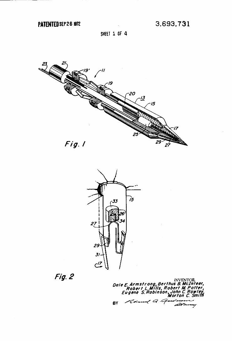
FIG. I is an isometric view partly in section using a nuclear reactor for power.
FIG. 2 is a vertical fragmentary detail of the rock drill housing and rock penetrator.
3,693,731 3
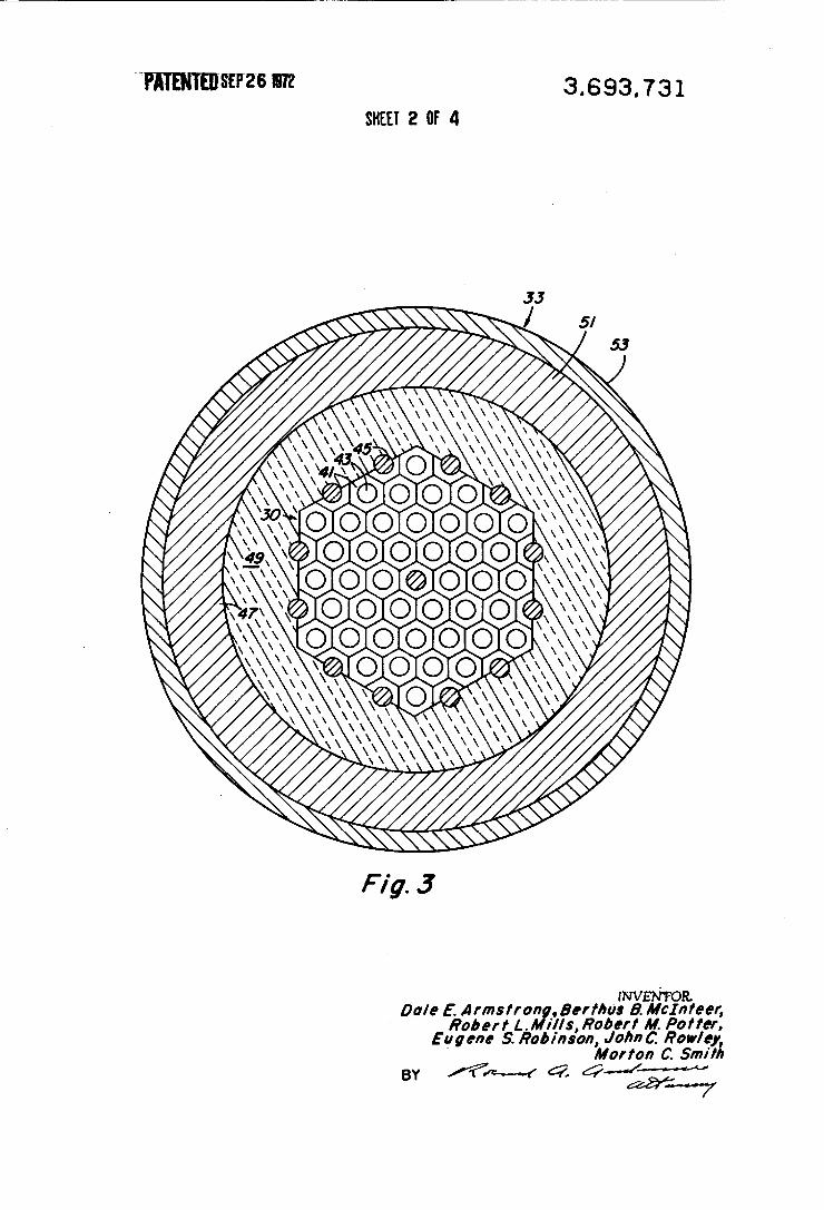
FIG. 3 is a cross section of a nuclear reactor suitable for use in the rock melting drill.
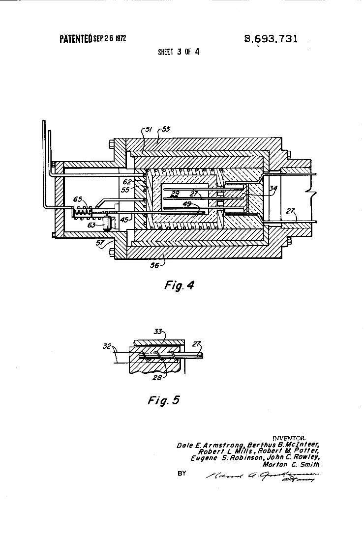
FIG. 4 is a longitudinal cross section of a nuclear reactor heat generator adapted for remote control.
FIG. 5 is a fragmentary view of an electrical heat source.
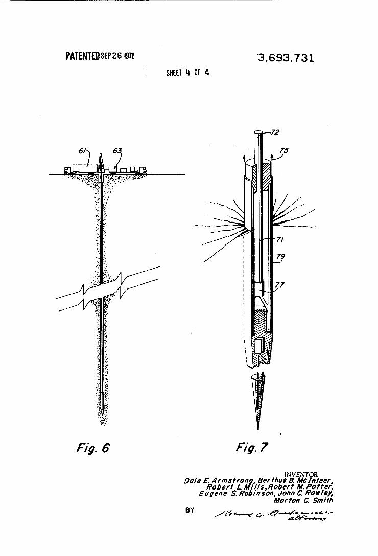
FIG. 6 is a plan view of a ?eld drilling facility. FIG. 7 is a rock drill adapted to extraordinary deep
drilling. '
Referring to FIG. I, an embodiment is shown of a rock melting drill designated generally by numeral II. The drill comprises a hollow housing 13 comprising a uniform cross section portion 15 and a nose portion 17 which may have any shape but is preferably tapered to a point and which hereinafter is termed “penetrator," a pair of thruster mechanisms l9-—l9', a control and guidance component 21 and utility supply lines 23. The prime energy source 26 may be the nuclear reactor 25 or an electrical heating mechanism such as shown in FIG. 5. Connected in heat transferring relation to the heat source are heat pipes 27 .
Referring to FIG. 2, the manner in which the conden sers 29 of heat pipes 27 are coupled to the penetrator is shown. Each heat pipe so coupled is terminated in ?at enlarged condenser section 29. The condenser sections are in tight thermal coupling with the interior of wall 31 of penetrator 17 as by clamping or welding.
Nuclear reactor 25 comprises essentially a core 30 shown in FIG. 3 and an insulation shield and armor covering 33. A heat coupling element 34 containing a liquid metal such as molten tin is supported in the reac tor and is thermally coupled to the evaporator ends of the heat pipes 27. The heat pipe 27 is shown as composed of end-to
end coupled heat pipe sections. The reason for this becomes apparent from further consideration of the heat pipe characteristics. For an operating temperature in the range of from l,400° to l,800°l( (1,127" to 1,527°C) the heat-pipe container is a gas-tight refracto ry metal tube or shell. The preferable appropriate working ?uid is lithium. Lithium heat pipes made of niobium-lpercent zirconium alloys have been operated at temperatures up to l,600°l( (1,327’C) for several thousand hours. Other materials such as alloys like tan talum-l0 percent tungsten are capable of operation to as high a temperature as 2,100°K (l,827°C). The heat pipe as an individual working element has
limited lift of the working ?uid by capillary action. In the rock melting drill the heat source may be supported several meters above the penetrator 17. The lithium heat pipe cannot effectively transport the working fluid vertically against the force of gravity a distance much in excess of one meter. However, as many heat pipe sections (each a complete heat pipe unit) can be con nected in series as the total distance requires and, as shown in FIG. 2, a plurality of heat pipe sections or units constitute each heat transfer heat pipe from the heat coupler 34 to the penetrator wall 31. A tunneling speed of I00 meters per day is well
within the heat transfer capabilities of the heat pipe. This speed of tunneling requires approximately $00 watts per square centimeter of penetrator worlt sur face. At l,400°K a lithium heat pipe can readily trans~ port l0 kilowatts per square centimeter of vapor passage cross-sectional area and at 1,800°K the capaci ty is increased by a factor of more than ?ve. Thus, each
5
20
25
30
35
45
50
55
60
65
4 square centimeter of vapor passage can supply heat to at least 30 square centimeters of penetrator surface. The heat source for the rock-melting drill to the
present invention can be electrical or nuclear. The nuclear reactor as the prime source of energy is preferred for very deep or very fast tunneling. Nuclear reactors of appropriate size and capability are available for the purpose. Reactors whose core contains about 40 volume percent heat pipes with a heat generating capacity of from I00 kW to 10 MW thermal power out put have a core size ranging from 18 cm diameter and 25 cm long to 1 meter diameter and 1 meter length. A cross section of a suitable nuclear reactor is shown
in FIG. 3 and it is similar to those developed for space nuclear and propulsion purposes. The core 30 com prises fuel elements 41 each of which has a hollow cavi ty 43 to accommodate a heat pipe evaporator end. Control rods 45 provide adjustability of heat energy generated to equal heat energy consumed in the penetrator and energy demand of accessory equip ment. The reactor core is surrounded with thermal blanket and nuclear shield 49 which in turn is protected by a heavy metal shield 51 and exterior armor 53. The core 30 and elements 49, SI and 53 constitute one practical assembly for the component 33 shown in FIG. 2 The combination of the nuclear reactor with the heat
pipes, remote control devices and coolant is explained with reference to FIG. 4. The nuclear reactor has a diametric cross section as shown in FIG. 3 except that in part the heavy metal shield 51 and armor 53 are combined into a water-cooled solid tungsten casing 55. Massive metal cage 56 provides for support of the reac tor core 29 and shielding and support for devices which are connected thereto. As shown in FIG. 6, the rock drill may be connected by drill stem 66 which encloses and extends the cables, pipes and electrical conductors to above-ground control and supply facilities 61 and 63. The cooling water is admitted to pipe ducts in con tact with or in the armor to cool the reactor as needed. The position of the control rod is remotely controlled by control drive motor 63. The reactor is provided with usual fail safe control system such as spring 64 conven tional reactor control type. In this embodiment the inlet and exhaust water pipes, the electrical supply ca bles and the main suspension cable form the main cabling or umbilical cord between the control truck and the drill. An electrical heat source instead of a nuclear reactor
is shown in FIG. 5. The electrical resistance 28 is in tight thermal contact with heat pipe 27 and is energized by electrical cables 32 leading to the earth's surface. Otherwise the penetrator is similar to the nuclear ener gized embodiment. With respect to any technique for drilling holes in the
earth the material removed to make the hole must be disposed of. In small holes such as shallow water wells in porous soils it has long been the technique to simply drive the material radially outward into the surround ing earth. In drilling larger holes or tunnels the problem of disposal grows rapidly, at least with the square power of the diameter of the hole. With respect to large holes such as one meter or larger, the technique of sideways disposal of solid debris is not feasible even in porous soils. ln solid rock this technique has hitherto not been
3,693,731 5
feasible for holes of any diameter. ln accordance with the present invention the debris may be disposed of as melted rock both as a lining for the hole and as a dispersal in cracks produced in the surrounding rock. The rock-melting drill is of a shape and is propelled under suf?cient pressure to produce and extend cracks in solid rock radially around the bore by means of hydrostatic pressure developed in the molten rock ahead of the advancing rock drill penetrator. All melt not used in glass-lining the bore is forced into the cracks where it freezes and remains. The ability of the rock melting drill to provide a
vitreous lining for the bore hole in rock or in other earth material such as sand, whether consolidated or unconsolidated in the original condition is a meritore ous advance in the art. Such a lining eliminates, in most cases, the expensive and cumbersome problem of debris elimination and at the same time achieves the advantage of a casing type of bore hole liner. Such a molded in situ casing serves a number of functions such as preventing escape of material from within the hole, preventing ingress of unwanted materials from without the hole, reducing resistance to passage of materials or objects through the hole, and providing wall support against forces developed within or without the hole. The feasibility of cracking subterranean rock by
pressure has been established, particularly in oil?eld experience by hydrofracturing. The forces involved and methods of fracturing by water pressure are discussed in publications, for example, E. Harrison et al., “The Mechanics of Fracture lnduction and Extru sion," Pet. Trans. AlME, 201, 252 (1954) and M. K. Hubbert et al., “Mechanics of Hydraulic Fracturing,“ Pet. Trans. AIME 2l0, 133 (1957). However the use of melted rock as the ?uid through which pressure is transmitted is novel with this invention. The rock-melting drill of the present invention pro
vides advantages over rock fracturing by pressure alone in that the heat induced in surrounding rock provides an effective cracking force. Most rocks are good ther~ mal insulators. The effect of an abrupt change in sur face temperature or of a heat ?ux suddenly applied to a rock surface will in general penetrate slowly. For exam ple, the heat properties of the material surrounding a cylindrical hole 2 meters in diameter in granite have been discussed in the literature by L. F. lngersoll et al., “Heat Conduction—With Engineering, Geological, and Other Applications," I954 University of Wisconsin Press. In brief, the pertinent data are: thermal conduc tivity = A = 0.0065 cal/cm-sec-°C; speci?c heat = c, = 0.19 callg-°C; density = p = 2.7 g/cm’; and thermal dif fusivity = D =0.0l27 cm'lsec. The surface temperature of the hole, T, is rapidly
raised from l00°C to about l,l00°C which is approxi mately the melting temperature of granite. To deter mine the temperature of the surrounding rock as a function of time and of dimensionless radial distance r/a from the hole, the parameter of interest is the non dimensional Fourier number F0 = (D/a')r. The speci?c origin of this mathematical approach is D. J. Schneider, “Temperature Response Charts," John Wiley & Sons, New York 1963. For the rock properties above given, F, = L26 X l0"
1 where t is in seconds. In one hour the thermal wave has migrated about one hole radius from the hole wall.
20
25
30
35
40
45
50
60
65
6 For the thermal wave to migrate 10 hole radii would take about 40 days. These results indicate that the ther mal perturbation in the earth caused by passage of a rock-melting penetrator is extremely local in nature. The thermal insulating properties of rock are favora
ble characteristics for limiting the energy consumed in boring and in creating stresses in the rock for creating cracks. Since the thermal perturbations are restricted to very thin layers adjacent to rock surfaces, the ther mal stresses generated in the zone of perturbation are easily estimated. The magnitude of the thermal stress can be derived from the relation
mtg-(Tag; (T.,— T.) where
a“, = thermal stress, kglcm' E = mean coe?'icient of thermal expansion, "C"I E = elastic modulus, kg/cm' v = Poisson ‘s ratio
T, = ambient temperature of undisturbed rock mass,
T,= ambient temperature of the rock surface, "C By substituting typical rock properties of 6 = 8 X 10-‘ °C"; E= l06 kg/cm' and v = 0.2, the
above relation becomes
Um a T.) =1
Since the tensile strengths of rocks are between 40 and 100 kg/cm’, a temperature decrease of 4° to 10°C in the zone adjacent the hole creates sufficient thermal stress to cause tensile cracking. The operation of the rock-melting penetrator may be
facilitated by the fact that the cracks started by thermal stress can be extended by lithofracture through the mechanism of high interface pressures produced by the thrust of a spear-shaped penetrator. Numerous data are in the public domain pertinent to the basic facts of frac turing, for example, the M. K. Hubbert et al. and the E. Harrison et al. publications in the AIME Transactions above identi?ed. Treatment of the crack extension behavior of rocks pressurized hydraulically has been made by R. J. Sun, "Theoretical Size of Hydraulically Induced Fractures and Corresponding Uplift in an idealized Medium,“ Journal of Geophysics Research, 74, 5995 ( I969). Speci?cally, it was demonstrated that the cracks formed from a hole 10 cm in diameter ex tended outward to distances of 50 to 60 meters, i.e., crack depths were 500 to 600 times the hole diameter. The volume of cracks of several different geometries,
formed in granite, are shown in the following table:
CALCULATED DIMENSIONS AND VOLUMES OF CRACKS FORMED lN GRANITE
Crack Crack Crack Net pressure, AP Radius, Width, Volume, Ln in en U, m‘ kg/cm' (lblin.')
S 0.2 0.1 l 165 (2,300) l0 0.5 L05 200 (2,800) 20 L0 8.0 200 (2,800) 50 I0 52.0 80 (l.l50) I00 20 420.0 80 (l,l50)
3,693,731 7
The data given show that lower pressures are required to form very long thin cracks than to form short, wide ones and that the long thin cracks have unexpectedly large volumes. For comparison: a l-meter length of a hole 2 meters in diameter has a volume of only 3. l4 m‘. As seen from the foregoing, the device of the present
invention works best when sufficient penetrator pres sure is used to force the melted excavated material into the adjacent rock. Under the requisite pressure, the hot spear-shaped penetrator is forced against the rock and a thin film of glass-like melt forms over its hot surface. This ?uid serves as a viscous pressure-transmitting medium to convert the axial thrust of the penetrator into uniformly distributed hydrostatic pressure on the wall of the hole. Stresses in the rock are very high at the tip of the penetrator and initiate cracking of the rock. The melted rock is forced into the cracks wherein heat is given up to the crack surfaces and freezes as a glass at some distance from the penetrator and serves to prop the crack open. If the ?ow of molten rock is premature ly stopped by the plugging of the cracks due to freezing, the walls of the bore hole are again subjected to large lateral hydrostatic forces and either the old cracks are enlarged or new cracks form to accept the molten rock. The rate of advance of the rock-melting penetrator is
governed by the rate at which the rock is melted, and this is controlled by the power delivered to the penetra tor surface. Cracking of the solid rock and rate of out ?ow of the melted rock depend upon the thrust applied to the penetrator. The pressure may either be obtained by a pusher
pipe or rod 66 made up of connected drill pipe seg ments and extending to the surface as shown in FIG. 6 or it can be a bore hole lock-on type of a type well known in the prior art such as schematically shown in FIG. I. The double compression lock-on device in general comprises two cylindrical thrusters l9 and 19' each being driven radially by hydraulic cylinders. Pusher hydraulic cylinders 20 with their hydraulic rams provide the prime mover force between the rock drill body and the lock-on thrusters 19. The thrust force needed for boring a two_meter diameter hole or tunnel is in the neighborhood of IS million pounds or roughly eight thousand tons. Six l4~inch hydraulic cylinders pressurized at 20,000 psi provide 18 million pounds of available controllable thrust which is more than adequate. The self-contained rock melter of FIG. 1 lends itself to remote-control operation. The rock-melting penetrator of this invention is par
ticularly applicable to drilling at depths totally inac cessible with previously available drilling techniques. Such deep drilling is exceedingly useful not only in the obtainment of data from beneath the earth's crust but also to tap essentially limitless geothermal energy. For example, beneath the Colorado plateau, the Mohorovicic discontinuity is at the anomalously shal low depth of about 30,000 meters which is well within reach of the embodiment of FIGS. 6 and 7. At this depth the normal geothermal gradient of 20°C/km results in a rock temperature of about 600"C and the overburden pressure is about 145,000 psi. The rock drill of the type shown in FIG. 7 wherein drill stem con nects the rock drill to the surface is applicable because a coolant ?uid circulation system is provided through the drill stem. Coolant passage 71 is provided in the
20
25
40
45
55
60
8 rock-drill body and is connected via pump 77 to porous metal wall 79. The fluid which exudes from the porous wall chills and strengthens the glass lining of the shaft and thermally protects the rock drill.
It is intended that at depths feasible to the operation, the FIG. I rock-melting drill will be guided by remote control. The feasibility of deep-hole radio control is provided by M. Dolukhanov, “Underground Propaga tion of Radio Waves," Radio (Moscow) I970. (English translation by Joint Publications Research Service. Publication No. JPRS 49894 (1970). The foregoing description of preferred embodiments
deals with nuclear reactor prime mover devices. It is within the contemplation of this invention that any other adequate heat generator may be used such as one which is electrical in nature. Accordingly, it will be ap parent that numerous departures from the details shown may be made within the spirit and scope of this invention and it is, therefore, understood that the in vention is limited only by the scope of the following claims. What we claim is: 1. Earth drilling apparatus for drilling bore holes and
tunnels in rock by melting a path for itself comprising an elongated hollow drill housing having a ?rst hollow portion and a second hollow portion, a heat source sup ported in said first hollow portion having a temperature of not less than about l,l00°C, heat pipe chains for thermally coupling the heat source to the interior sur face of the walls of the said second hollow portion, each of said heat pipes comprising a plurality of ther mally coupled heat pipe sections, each of the heat pipe sections having an evaporator end and a condenser end, and being coupled with the condenser end of a preceding heat pipe being adjacent the evaporator end of the next succeeding heat pipe, the initial evaporator of each of the heat pipe chains is supported in close thermal contact with the heat source and the terminal condenser of each heat pipe chain is affixed in tight thermal conductive relation to the interior wall of the said second hollow portion, and propulsion means sup ported by the said ?rst hollow portion for translating the drilling apparatus in the direction of elongation.
2. The apparatus of claim I in which the propulsion means is a double thruster bore hole lock-on mechanism and means for operating the double thruster comprising a source of hydraulic ?uid under pressure and hydraulic rams supported in the drill housing ?rst portion.
3. The apparatus of claim I in which the walls of the housing second portion converge toward the forward end whereby molten rock is distributed laterally against the bore hole walls to in situ form a vitreous casing thereon.
4. The apparatus of claim I in which the propulsion means is a drill pipe stem made up of standard drill pipe segments and having a length coextensive with the bore hole plus one additional pipe segment or a portion thereof, said drill pipe stern being connected at one end to the rearward end of the drill housing first section and extending out of the bore hole at its other end, whereby said drill stem is adapted to forcefully urge the rock drill forward by its own weight and by force applied to said other end.
3,693,731 9
5. The apparatus of claim 4 in which the walls of the heat source and drill ?rst section are water cooled, water transmission means, hydraulic pressure hoses and electrical power transmitting conductors being housed and supported in the drill stem.
6. The apparatus of claim 5 in combination with a surface facility, said surface facility comprising electri cal generating means, electrical signaling means, water coolant storage and pumping means and vertical force generating means, electrical conducting means con
5
IS
20
25
30
35
40
45
50
$5
60
65
necting the electrical generating means to the electrical power transmitting conductors, coupling means for coupling the signaling means to the rock drill, and hoses connected between the coolant pumping and storage means and the rock drill water transmission means for circulating water through the heat source armor and drill body ?rst section for cooling the same and conveying the heat thereby obtained to the surface facility.
I‘ i i i i