metec controlled test protocol: continuous monitoring
TRANSCRIPT

Continuous Monitoring Protocol Daniel Zimmerle, 970-581-9945, [email protected]
1
1
METEC Controlled Test Protocol: 2
Continuous Monitoring Emission Detection And Quantification 3
Revision 1.0 4
September 22, 2020 5
1 Purpose: 6
This testing will assess the performance of continuous monitoring (CM) systems which perform leak 7
detection and quantification (LDAQ) under Single-Blind controlled release testing over a range of 8
environmental conditions and emission rates. Testing will evaluate system-level performance measures 9
including Probability of Detection and Detection Time. Additional metrics including accuracy and 10
precision of localization and quantification estimates will be evaluated if applicable. Due to the 11
dependence of methods on weather conditions, testing will require an extended period, typically 12
months, with active emission and non-emissions periods to (1) allow each Experimental Design Point to 13
operate for an extended duration, typically hours, and (2) assess performance across a wide range of 14
meteorological conditions. 15
2 Definitions 16
o Continuous Monitor (CM) – An Emission Detection System in which sensors are installed to 17
autonomously monitor a facility without direct human supervision or intervention for an 18
extended period of time. A Continuous Monitor may operate continuously or at specific 19
intervals. 20
o Controlled Release (CR) – A type of experiment where emissions are intentionally created for 21
the purpose of evaluating emission detection and/or quantification systems. During a Controlled 22
Release, the emission rate and location are known to the Test Center within well understood 23
accuracy. 24
o Detection – An alert provided by an Emission Detection System to the Facility operator that an 25
Emission is present. An elevated gas concentration measurement alone does not constitute a 26
Detection, but instead must be accompanied by analytics or further evaluation to attribute the 27
elevated concentration to an Emission within the Facility. This attribution must be established 28
with a high enough confidence to warrant providing a detection alert to the Facility operator. 29
o Detection Time (DT) – The time between when a Controlled Release was first emitted and when 30
a Detection was first reported to the Test Center. See section 6.2.4. 31
o Emission – a release of gas to the ambient environment. 32

Continuous Monitoring Protocol Daniel Zimmerle, 970-581-9945, [email protected]
2
o Emission Detection System – A system comprised of one or more sensors and associated 33
analytics capable of detecting emissions and attributing them, at minimum, to a facility. 34
Emission Detection Systems may include analytics to categorize emissions as Fugitive or Vent, 35
and/or to provide emission rate quantification estimates. 36
o Equipment Group – A set of Equipment Units in proximity of one another. 37
o Equipment Unit – An individual unit of equipment such as a wellhead, separator, or liquid 38
storage tank. 39
o Experimental Design (a test matrix) – A set of Experimental Design Points defined to investigate 40
correlation between variation in a dependent variable and variation of one or more 41
independent variables. 42
o Experimental Design Point (an experiment) – A single combination of settings for the 43
independent variables of a controlled release experiment. Independent variables include both 44
the emission rate of the Controlled Release(s) and environmental conditions. 45
o Facility – A set of equipment with a common purpose and defined boundary which may be 46
physical (such as a fenceline) or implied. 47
o False Negative (FN) – A Controlled Release which was not detected by a Performer. See section 48
6.1 for classification of Detections. 49
o False Negative Fraction (FNF) – The number of False Negative Controlled Releases relative to the 50
total number of Controlled Releases. See section 6.2.3. 51
o False Positive (FP) – A Detection reported by a Performer that cannot be attributed to a 52
Controlled Release. See section 6.1 for classification of Detections. 53
o False Positive Fraction (FPF) – The number of False Positive Detections relative to the total 54
number of Detections. See section 6.2.2. 55
o Final Report – A report issued by the Test Center after the conclusion of testing. See section 8. 56
o Fugitive – An unintentional emission associated with a leak, upset condition, or malfunction. 57
Examples include leaks, stuck valves, or excess emissions from normally venting components. 58
o Localization Accuracy (LA)– A measure of the distance between the location of an emission as 59
estimated by a Performer and the location where a Controlled Release occurred. In this protocol 60
location accuracy is 2D. Three localization accuracies may be calculated based on (1) an 61
Equipment Unit, (2) a single latitude-longitude coordinate pair, or (3) a pair of coordinates 62
indicating a bounding box reported by the Performer (see sections 6.2.6, 6.3.5 and 6.3.6 63
respectively). 64

Continuous Monitoring Protocol Daniel Zimmerle, 970-581-9945, [email protected]
3
o Localization Precision (LP) – A measure of the area to which an emission source is attributed by 65
a Performer. Two Localization Precisions may be calculated based on (1) an Equipment Unit, or 66
(2) a pair of coordinates indicating a bounding box reported by the Performer (see sections 6.2.5 67
and 6.3.8 respectively). 68
o Operational Factor (OF) – The fraction of time which a CM is operational. See section 6.2.7. 69
o Performer – A single participant in the testing under this protocol. The Performer includes the 70
personnel and one Continuous Monitoring system. 71
o Probability of Detection (PD) – Fraction of Controlled Releases, over a set of Experimental 72
Design Points, that the Performer reported as Detections. The Probability of Detection may vary 73
across independent variables such as the emission rate and/or the meteorological conditions, 74
resulting in a Probability of Detection curve or surface. See section 6.2.1. 75
o Quantification Accuracy (QA) – A measure of the difference between the emission rate 76
estimated by a Performer and the metered emission rate of a Controlled Release. Quantification 77
Accuracy may be represented as an absolute difference, or as a percentage difference relative to 78
the metered emission rate (see sections 6.3.1 and 6.3.2 respectively). 79
o Quantification Precision (QP) – A measure of the difference between the upper and lower 80
confidence limits reported by a Performer for an emission rate estimate (see sections 6.3.3 and 81
6.3.4 respectively). 82
o Single-Blind – An experimental procedure in which the Test Center knows the location, timing, 83
and emission rate of all emissions, but Performers do not. 84
o Test Center – The location at which testing is performed under this protocol. The term ‘Test 85
Center’ includes the physical facilities, the personnel performing the evaluation, and any 86
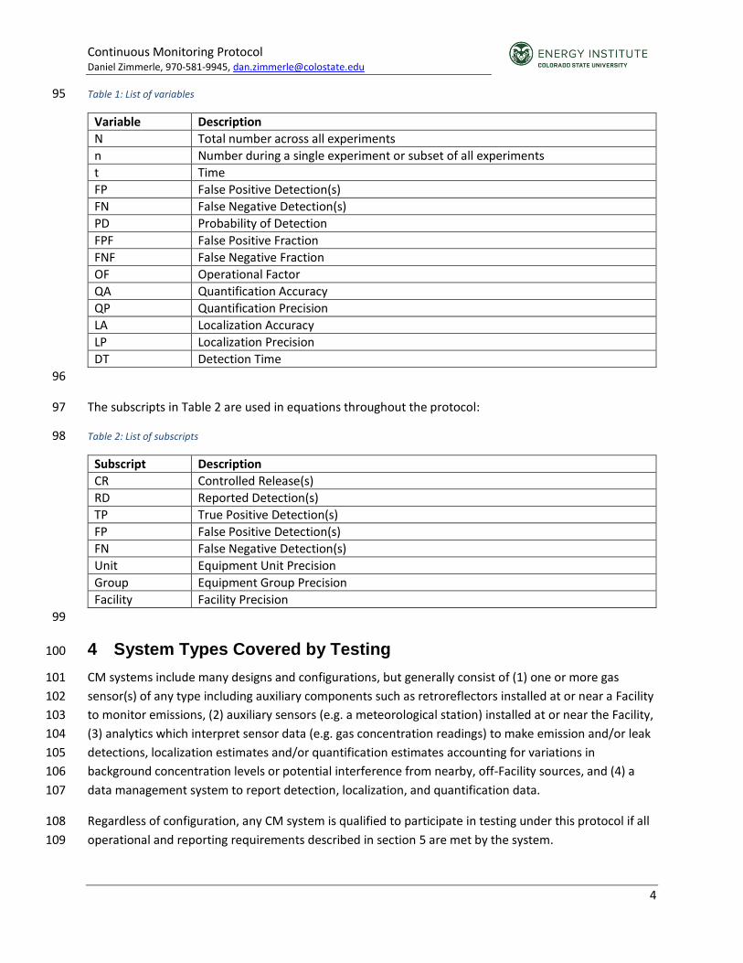
supporting software or analysis. 87
o True Positive (TP) – A Detection reported by a Performer that can be attributed to a Controlled 88
Release. See section 6.1 for classification of Detections. 89
o Vent – An intentional emission associated with a process. Examples include venting from gas 90
pneumatics, compressor rod packing, tank vent emissions from uncontrolled tanks, and 91
equipment blowdowns. 92
3 Variables and Subscripts 93
The variables listed in Table 1 are used in equations throughout the protocol: 94
Continuous Monitoring Protocol Daniel Zimmerle, 970-581-9945, [email protected]
4
Table 1: List of variables 95
Variable Description
N Total number across all experiments
n Number during a single experiment or subset of all experiments
t Time
FP False Positive Detection(s)
FN False Negative Detection(s)
PD Probability of Detection
FPF False Positive Fraction
FNF False Negative Fraction
OF Operational Factor
QA Quantification Accuracy
QP Quantification Precision
LA Localization Accuracy
LP Localization Precision
DT Detection Time
96
The subscripts in Table 2 are used in equations throughout the protocol: 97
Table 2: List of subscripts 98
Subscript Description
CR Controlled Release(s)
RD Reported Detection(s)
TP True Positive Detection(s)
FP False Positive Detection(s)
FN False Negative Detection(s)
Unit Equipment Unit Precision
Group Equipment Group Precision
Facility Facility Precision
99
4 System Types Covered by Testing 100
CM systems include many designs and configurations, but generally consist of (1) one or more gas 101
sensor(s) of any type including auxiliary components such as retroreflectors installed at or near a Facility 102
to monitor emissions, (2) auxiliary sensors (e.g. a meteorological station) installed at or near the Facility, 103
(3) analytics which interpret sensor data (e.g. gas concentration readings) to make emission and/or leak 104
detections, localization estimates and/or quantification estimates accounting for variations in 105
background concentration levels or potential interference from nearby, off-Facility sources, and (4) a 106
data management system to report detection, localization, and quantification data. 107
Regardless of configuration, any CM system is qualified to participate in testing under this protocol if all 108
operational and reporting requirements described in section 5 are met by the system. 109

Continuous Monitoring Protocol Daniel Zimmerle, 970-581-9945, [email protected]
5
Note: Systems tested under this protocol must implement appropriate analytics to report Detections, and 110
are encouraged to report localization and quantification estimates. A CM system that produces 111
concentration readings (e.g. ppm or ppm-m), or plume pictures or video, without the analytics to analyze 112
those readings and report Detections, is not supported by this protocol. 113
Testing under this protocol will operate for multiple weeks, 24 hours per day, 5-7 days per week. 114
Therefore, a system where a sensor is not weatherproof, is moved around on a single Facility, is moved 115
between facilities, or requires frequent attention by personnel other than routine maintenance and 116
calibrations as discussed in section 5.2, is not suitable for testing under this protocol.1 117
5 Test Method 118
Testing consists of four activities – installation, maintenance, operation, and reporting. 119
5.1 Installation 120
Performers will schedule with Test Center for installation. 121
5.1.1 Location of System Components 122
The location of system components may be selected by the Performer to best represent their 123
methodology when deploying at customer locations, subject to approval by the Test Center. The Test 124
Center may provide recommended locations or infrastructure where available. A Test Center may 125
articulate specific restrictions on deployment locations and requirements. Typically, selected locations 126
must meet the following guidelines: 127
1) Installations shall not inhibit vehicle or foot traffic on roadways and walkways on or around 128
the Test Center. 129
2) System components shall not introduce an undue safety hazard including but not limited to 130
loose cabling, exposed wires, tripping hazards, unmarked guy cables, or unsecured overhead 131
components. 132
3) System components shall comply with hazardous space/ATEX requirements of the Test 133
Center. 134
4) When required, Performers shall attain permission to install components outside of the Test 135
Center from the land owner or operator. 136
5.1.2 Power 137
Performers are encouraged to provide their own power for sensors or auxiliary equipment, ideally using 138
the same power subsystems as would be used in a field deployment. The Test Center may provide 139
access to power for use by Performer CM systems if available; locations where power is available may 140
be restricted by the Test Center. Performers should work with the Test Center to determine a safe and 141
1 Other protocols will address survey systems that move between facilities, and human operated sensors.

Continuous Monitoring Protocol Daniel Zimmerle, 970-581-9945, [email protected]
6
effective power plan including approval of any connections to Test Center infrastructure, mounting 142
locations for PV panels, batteries, or other power equipment. 143
5.1.3 Data Communications 144
The Test Center may provide a wired network connection if available, or Performers may be required to 145
provide their own data communications via wireless mechanisms. Performers are encouraged to use the 146
same (or similar) communications methods as would be used in field deployments. 147
5.1.4 Meteorological Data 148
Systems must install their own meteorological station if local meteorology is required, subject to 149
approval by the Test Center. Performers are encouraged to use the same meteorological system(s) as 150
would be used in field deployment. 151
5.1.5 Installation Documentation 152
The configuration of the system under test shall be documented and reported to the Test Center. 153
Documentation must be sufficient for a reviewer to fully identify the ‘as tested’ revision and 154
configuration of the CM system. At a minimum, documentation shall include: 155
1. Location (latitude, longitude, height) of system components including central instruments, 156
meteorological station, retroreflectors, sensor nodes, or any other equipment installed at or 157
near the Test Center. 158
2. Model number of each component in (1). 159
3. Power configuration of each component in (1) 160
4. Revision number of software installed in each component in (1) that includes performer-specific 161
software components, revisions, or customizations. 162
5. Revision number of any software analytics installed offsite. 163
6. Confidence level at which emission detection data are reported. 164
Installation documentation should be considered public information, and Performers should not include 165
proprietary information (e.g. algorithmic details, reasons for locating sensor in specific locations, 166
performance data of sensors, etc.) as part of this documentation. 167
5.1.6 Installation Cautions 168
Performers should recognize results are applicable only to the CM system as tested and documented. 169
Future reviewers of results will be interested in whether systems proposed for field deployment include 170
the same density and quality of sensors (or other equipment) as were tested under the protocol. 171
Deploying more sensors, higher cost-performance sensors, more extensive analytics, or more human 172
intervention than would be typical in field deployments may render the results produced in these tests 173
inapplicable to future field deployments, regulatory applications, or other uses of the test results. 174

Continuous Monitoring Protocol Daniel Zimmerle, 970-581-9945, [email protected]
7
5.1.7 Non-Compatible Systems 175
If multiple Performers installed at a Test Center are identified as incompatible due to data 176
communications platforms, positioning of sensors, or other reasons the Test Center and Performers will 177
work to resolve the issue on a case-by-case basis. The Test Center will not always be able to identify 178
these issues in advance of installation. If a conflict cannot be resolved via discussion between impacted 179
Performers and the Test Center, the decision of the Test Center is final. 180
5.2 Maintenance 181
Performers are expected to complete any maintenance required to keep the installed system 182
operational for the duration of the test period. This includes but is not limited to required calibration, 183
cleaning, component replacement, or unit replacement. Performers must notify the Test Center to 184
schedule maintenance as needed. Performers will provide documentation of maintenance tasks 185
performed and the total time onsite during each maintenance visit. Maintenance records will be 186
included in the Final Report at the conclusion of testing. 187
Performers may train Test Center personnel to perform simple maintenance tasks such as power cycling 188
or cleaning of external lenses. Tasks qualifying as “simple maintenance” will be at the discretion of the 189
Test Center. Test Center personnel will not perform troubleshooting or additional maintenance of 190
systems. Maintenance performed by Test Center personnel will be recorded and included in the Final 191
Report. 192
Periods when the CM system is not operational must be reported to the Test Center using method 193
described in section 5.4.2, and will be used to compute the Operational Factor. 194
Performers may adjust or modify their installations during maintenance visits. Modifications of the 195
installed system during the test period must be documented by the Performer and reported to METEC 196
including the date which the installation was modified and the full documentation of the new 197
configuration as defined in section 5.1.5. System modifications will be included in the Final Report. 198
5.3 Operation 199
Performer staff will not be present at the Test Center during the operation period except to complete 200
required maintenance as discussed in section 5.2. During the operation period: 201
1) The Test Center will perform Controlled Releases as outlined in section 7. For each 202
Controlled Release, the Test Center will record the location, timing, gas composition, 203
metered emission rate, and uncertainty (95% confidence limit) of the metered emission 204
rate. 205
2) Performers will remotely monitor their sensors and complete any necessary back-end 206
analytics to translate sensor readings into emission detection reports as described in section 207
5.4. 208
3) Performers will send emission detection reports to the Test Center. Emission detection 209
reports must include the data fields outlined in section 5.4. Performers will also send reports 210

Continuous Monitoring Protocol Daniel Zimmerle, 970-581-9945, [email protected]
8
to the Test Center to indicate periods when their CM system is operational or non-211
operational. 212
4) The Test Center will record the time which Performer emission detection reports are 213
received and store them for results analysis. 214
Due to the extensive nature of this test protocol, there may be periods when planned or unplanned 215
conditions may disrupt the testing within the Facility boundary at the Test Center (Facility boundary 216
defined in section 7.1). In these scenarios, the Test Center will inform Performers of the dates of 217
disruptive testing, and will not consider Controlled Releases or Detections during the identified period in 218
the analysis. The Test Center will make every reasonable effort to inform Performers in advance of a 219
planned disruption, or, if unplanned, as quickly as possible after the disruption commences. 220
5.4 Reporting 221
This section outlines data which must be reported by the Performer to the Test Center during the 222
experiments. Two categories of data, detection reports and online/offline reports, must be reported in 223
order for the Test Center to complete the classification of detections (section 6.1), evaluate all primary 224
metrics (section 6.2), and evaluate optional secondary metrics (section 6.3). 225
5.4.1 Detection Reports 226
Detection reports allow Performers to indicate when a new emission is detected, or to update a 227
previously detected emission. Detection reports include estimates by the Performer for the timing, 228
location, and quantification of each detected emission. Each detection report must be for a single 229
emission and must contain, at minimum, all mandatory fields listed in Table 3. Optional fields listed in 230
Table 3 may be included if the CM is capable of reporting these additional data. Performers that are 231
capable of reporting optional data fields are encouraged to do so in order to support the evaluation of 232
secondary metrics under the same series of experiments. 233

Continuous Monitoring Protocol Daniel Zimmerle, 970-581-9945, [email protected]
9
Table 3: Detection report fields 234
Field Description Acceptable Values
Mandatory or
Optional
DetectionReportID
A unique ID assigned by the Performer to the individual detection report. This number should be incremented for every detection report sent. Duplicate numbers will be assumed to be multiple transmissions of the same report; only one (the first received) report will be logged. The increment amount between reports is arbitrary and need not be constant; report ID should never be decremented.
Positive Integer Mandatory
DetectionReportDateTime
Date and time (Coordinated Universal Time, UTC) at which this detection report was generated in yyyy/mm/dd hh:mm format
Formatted Date & Time
Mandatory
EmissionStartDateTime Estimated date and time (UTC) at which the emission source began to emit in yyyy/mm/dd hh:mm format
Formatted Date & Time
Mandatory
EmissionEndDateTime
Estimated date and time (UTC) at which the emission source stopped emitting in yyyy/mm/dd hh:mm format If the emission has not stopped yet this field may be omitted or reported as NULL
Formatted Date & Time
Optional
EmissionSourceID
A unique ID assigned by the Performer to the individual emission source the detection report refers to. Updates to any parameter for this detection should utilize the same EmissionSourceID
Positive Integer Mandatory
Gas The gas the CM system measured to perform a detection.
List provided by Test Center
Mandatory

Continuous Monitoring Protocol Daniel Zimmerle, 970-581-9945, [email protected]
10
Field Description Acceptable Values
Mandatory or
Optional
EquipmentUnit
The Equipment Unit ID on which the emission was detected. An emission source attributed within the defined Facility but not attributed to an Equipment Unit should be reported as OTHER. An emission source detected by a CM but not attributed to the Facility may be reported as
OFF_FACILITY.
List provided by Test Center
Mandatory
Latitude1
If a bounding box is reported, the southern-most latitude of the bounding box in decimal degrees. Otherwise, the estimated latitude of the emission source location in decimal degrees.
Maximum and minimum values provided by Test Center
Optional
Latitude2
If a bounding box is reported, the northern-most latitude of the bounding box, in decimal degrees. Otherwise this field may be omitted
or reported as NULL.
Maximum and minimum values provided by Test Center
Optional
Longitude1
If a bounding box is reported, the eastern-most longitude of the bounding box, in decimal degrees. Otherwise, the estimated longitude of the emission source in decimal degrees.
Maximum and minimum values provided by Test Center
Optional
Longitude2
If a bounding box is reported, the western-most longitude of the bounding box, in decimal degrees. Otherwise this field may be omitted
or reported as NULL.
Maximum and minimum values provided by Test Center
Optional
EmissionRate
Estimated emission rate of the source. The units of this field should be grams per hour of the gas specified in Gas.
Decimal number >0 Optional

Continuous Monitoring Protocol Daniel Zimmerle, 970-581-9945, [email protected]
11
Field Description Acceptable Values
Mandatory or
Optional
EmissionRateUpper
Upper estimate of emission rate of the source. The units of this field should be grams per hour of the gas specified in Gas. If EmissionRateUpper is reported, EmissionRateLower must also be provided.
Decimal number >0 Optional
EmissionRateLower
Lower estimate of emission rate of the source. The units of this field should be grams per hour of the gas specified in Gas. If EmissionRateLower is reported, EmissionRateUpper must also be provided.
Decimal number ≥0 Optional
EmissionCategory
Emission category of the detection. Used only in the second experimental variation (see section 7.3.2).
FUGITIVE
VENT Optional
235
As a CM collects additional data to improve confidence in a quantification estimate or localization 236
estimate, or to notify end of emission, additional detection reports may be provided referencing the 237
same EmissionSourceID. Detection reports referencing the same EmissionSourceID will be grouped 238
together in the metrics to match Detections to Controlled Releases. Detection reports providing updated 239
information for a single field should provide a complete detection report including all other data fields, 240
not just the field or subset the Performer wishes to update. 241
Localization estimates may be reported as a single set of coordinates, or as a bounding box defined by a 242
maximum and minimum latitude and longitude. 243
5.4.2 Offline Reports 244
Offline reports allow Performers to indicate when a CM is not operating during the testing period. 245
These reports will be used (1) to compute the fraction of time the system was operational relative to the 246
total testing time, and (2) to limit the metrics to include only results from Controlled Release 247
experiments performed while the system is online. 248
Each offline report must contain, at minimum, all mandatory fields listed in Table 4. Optional fields 249
listed in Table 4 may be included. 250

Continuous Monitoring Protocol Daniel Zimmerle, 970-581-9945, [email protected]
12
Table 4: Offline report fields 251
Field Description Acceptable Values Mandatory or Optional
OfflineReportID
A unique ID assigned by the Performer to the individual offline report. This number should be incremented for each and every offline report sent. Duplicate numbers will be assumed to be multiple transmissions of the same report; only one (the first received) report will be logged.
Integer Mandatory
OfflineReportDateTime
Date and time (UTC) at which this offline report was generated in yyyy/mm/dd hh:mm format
Formatted Date & Time Mandatory
OfflineDateTime
Date and time (UTC) at which the system went offline in yyyy/mm/dd hh:mm format
Formatted Date & Time Mandatory
OnlineDateTime
Date and time (UTC) at which the system returned online in yyyy/mm/dd hh:mm format
Formatted Date & Time Mandatory
OfflineReason Reason why system went offline
ROUTINE_MAINTENANCE
ENVIRONMENTAL_CONDITIONS
SYSTEM_FAULT
COMMUNICATION_FAULT
Optional
252
5.4.3 Data Formatting and Responsibilities of the Test Center 253
The Test Center will establish, in advance of testing, how Detection Reports and Offline Reports shall be 254
submitted by the Performer. The Test Center may provide data formatting requirements to the 255
Performer to standardize the analysis performed by the Test Center. The Test Center must record the 256
date and time which data were received from the Performer for inclusion in the analysis and Final 257
Report. The time which emission detection reports are received by the Test Center will be used to 258
evaluate the Detection Time metric (see 6.2.4). It is encouraged that the Test Center establish a “real-259
time” data reporting method to allow the Detection Time metric to estimate the elapsed time between 260

Continuous Monitoring Protocol Daniel Zimmerle, 970-581-9945, [email protected]
13
when an emission source starts and when a CM provides an alert to the operators identifying the 261
emission on the Facility. 262
6 Performance Metrics 263
To evaluate performance metrics, detection reports and Controlled Releases will first be classified as 264
True Positive or False Positive Detections. Results will then be used to evaluate primary and secondary 265
metrics. Primary metrics will be evaluated for all CM systems under test; secondary metrics will be 266
evaluated for systems that report optional data fields. 267
Caution: Performance metrics and the operational and environmental conditions during the experiment 268
will be reported in the Final Report (see section 8). Performance metrics may only be applicable under 269
the conditions tested and caution should be exercised in extrapolating test results to operational or 270
environmental conditions not encountered during the testing period. 271
6.1 Classification of Detections 272
Detection reports which refer to the same EmissionSourceID will be grouped together as one 273
“Detection” during the classification process. The order of the detection reports referring to the same 274
EmissionSourceID will be determined using the DetectionReportID field; the ‘first’ report is the detection 275
report with the smallest DetectionReportID, the ‘last’ detection report is the detection report with the 276
largest DetectionReportID. The data in the last detection report for each Detection will be used in the 277
classification process. 278
Prior to classification the following Controlled Releases and Detections will be removed from the 279
classification process: (1) Controlled Releases which occur during experiments entirely within a period 280
where the CM was reported offline by the Performer (see section 5.4.2), and (2) Detections where the 281
EquipmentUnit is OFF_FACILITY in the last detection report. Controlled releases removed in this 282
step will not be classified as False Negatives. Detections removed in this step will not be classified as 283
True Positives or False Positives. 284
Note: Performers should note that the last detection report will be utilized for matching, and detections 285
with a location OFF_FACILITY will be removed from the matching. This allows a CM to identify a 286
possible emission as early as possible, but also to change the location to locate it outside the facility 287
boundaries later, eliminating a possible False Positive Detection. 288
The Test Center will perform the classification using the following process for each experiment: 289
1. The list of Controlled Releases performed within the Facility boundary during the experiment 290
will be sorted by Equipment Unit, then by emission rate in descending order. 291
2. The list of all Detections where EmissionStartDateTime is between the start time and end time 292
of the experiment will be sorted by EquipmentUnit, then by EmissionRate (if reported) in 293
descending order. 294

Continuous Monitoring Protocol Daniel Zimmerle, 970-581-9945, [email protected]
14
3. For each Controlled Release in (1), if a Detection in (2) is reported on the same Equipment Unit, 295
the Detection and Controlled Release will be paired as a True Positive Detection and removed 296
from further matching. True Positives matched in this step will be identified as correct unit 297
Detections (see section 6.2.5). 298
4. The list of Controlled Releases and list of Detections remaining after (3) will be resorted by 299
Equipment Group, then by emission rate in descending order. 300
5. For each Controlled Release in (4), if a Detection in (4) is reported on the same Equipment 301
Group, the Detection and Controlled Release will be paired as a True Positive Detection and 302
removed from further matching. True Positives matched in this step will be identified as correct 303
group Detections (see section 6.2.5). 304
6. The list of Controlled Releases and list of Detections remaining after (5) will be resorted by 305
Facility, then by emission rate in descending order. 306
7. For each Controlled Release in (6), if Detection in (6) is reported on the same Facility, the 307
Detection and Controlled Release will be paired as a True Positive Detection and removed from 308
further matching. Detections where EquipmentUnit = OTHER will be interpreted as on the 309
Facility in this step. True Positives matched in this step will be identified as correct Facility 310
Detections (see section 6.2.5). 311
8. Any Controlled Releases remaining after (7) will be identified as False Negative Detections. 312
9. Any Detections remaining after (7) will be identified as False Positive Detections. 313
This process will classify all Detections attributed to the Facility as either True Positive or False Positive, 314
and all Controlled Releases occurring on the Facility as either True Positive or False Negative, and result 315
in the three possible scenarios illustrated in Table 5 for each experiment when the CM is online. If the 316
number on Controlled Releases, 𝑛𝐶𝑅, is greater than the number of reported Detections, 𝑛𝑅𝐷, then each 317
reported Detection will be classified as True Positive and the remaining Controlled Releases will be 318
classified as False Negative. If the number of Controlled Releases is equal to the number of reported 319
Detections, then each reported Detection will be classified as True Positive and no Controlled Releases 320
will be classified as False Negative. If the number of Controlled Releases is less than the number of 321
reported Detections, then each Controlled Release will be classified as True Positive and the remaining 322
Detections will be classified as False Positive. 323
Table 5: Detection classification outcomes for each experiment 324
Relationship between 𝑛𝐶𝑅 and 𝑛𝑅𝐷
Number of True Positives, 𝑛𝑇𝑃
Number of False Positives, 𝑛𝐹𝑃
Number of False Negatives, 𝑛𝐹𝑁
𝑛𝐶𝑅 > 𝑛𝑅𝐷 𝑛𝑅𝐷 0 𝑛𝐶𝑅 − 𝑛𝑅𝐷
𝑛𝐶𝑅 = 𝑛𝑅𝐷 𝑛𝑅𝐷 0 0
𝑛𝐶𝑅 < 𝑛𝑅𝐷 𝑛𝐶𝑅 𝑛𝑅𝐷 − 𝑛𝐶𝑅 0
325

Continuous Monitoring Protocol Daniel Zimmerle, 970-581-9945, [email protected]
15
6.2 Primary Metrics 326
The following performance metrics have been identified as primary metrics: 327
6.2.1 Probability of Detection 328
Probability of Detection (PD) will be calculated as a curve or surface. Detection data will be binned by 329
conditions (environmental and controlled). For each set of conditions the PD will be calculated as the 330
number of True Positive Detections divided by the sum of the number of True Positive Detections and 331
False Negative Detections in the relevant conditions: 332
𝑃𝐷|𝑥 =𝑛𝑇𝑃
𝑛𝑇𝑃 + 𝑛𝐹𝑁 |
𝑥
333
Where 𝑥 is the combination of conditions at which the PD is evaluated at. 334
PD results will be calculated for the following three cases unless otherwise agreed by the Performer and 335
Test Center: 336
1) PD vs emission rate 337
2) PD vs average wind speed 338
3) PD vs emission rate and average wind speed 339
The Performer may request PD be calculated against an independent variable other than wind speed, if 340
they believe the performance of their CM solution is more impacted by another, recorded and available 341
variable. The Performer may also request only (1) to be calculated with (2) and (3) omitted, producing 342
only a PD curve instead of a surface or series of curves. While the Final Report will contain only the 343
requested PD curve/surface, all data will be released, and other parties may compute other PD 344
curves/surfaces. 345
6.2.2 False Positive Fraction 346
The False Positive Fraction will be calculated for the set of all experiments as the number of False 347
Positive Detections divided by the total number of reported Detections. 348
𝐹𝑃𝐹 =𝑁𝐹𝑃
𝑁𝑅𝐷=
𝑁𝐹𝑃
𝑁𝐹𝑃 + 𝑁𝑇𝑃 349
The False Positive Fraction does not represent the rate at which a Performer reported a Detection when 350
there were no emissions at the Facility. 351
6.2.3 False Negative Fraction 352
The False Negative Fraction will be calculated for the set of all experiments as the number of False 353
Negatives divided by the total number of Controlled Releases. 354
𝐹𝑁𝐹 =𝑁𝐹𝑁
𝑁𝐶𝑅 355

Continuous Monitoring Protocol Daniel Zimmerle, 970-581-9945, [email protected]
16
The False Negative Fraction does not represent the rate at which controlled emissions were undetected 356
by a Performer. 357
6.2.4 Detection Time 358
Detection Time will be calculated for each True Positive Detection as the time between the start of the 359
Controlled Release and the time when the matched Detection was received by the Test Center. If the 360
matched Detection includes multiple detection reports for the same EmissionSourceID, the Detection 361
Time will consider the time which the first detection report was received. 362
6.2.5 Localization Precision (Equipment Unit) 363
For primary metrics, localization uses only the EquipmentUnit provided in the detection report to 364
determine the precision of each True Positive. If the True Positive Detection includes multiple detection 365
reports for the same EmissionSourceID, the Localization Accuracy will consider the EquipmentUnit of the 366
last detection report received. Each True Positive Detection will be classified into one of three levels of 367
precision, from most precise to least precise: 368
1) Correct unit: The EquipmentUnit was the Equipment Unit on which the Controlled Release 369
occurred. 370
2) Correct group: The EquipmentUnit was in the Equipment Group where the Controlled Release 371
occurred. 372
3) Correct Facility: The EquipmentUnit was within the facility boundary where the controlled 373
release occurred. 374
6.2.6 Localization Accuracy (Equipment Unit) 375
Localization Accuracy will be calculated for the set of all experiments as the fraction of reported 376
Detections at each level of precision. 377
1) Correct unit: 378
𝐿𝐴𝑈𝑛𝑖𝑡 =𝑁𝑇𝑃𝑈𝑛𝑖𝑡
𝑁𝑅𝐷=
𝑁𝑇𝑃𝑈𝑛𝑖𝑡
𝑁𝑇𝑃 + 𝑁𝐹𝑃 379
2) Correct group 380
𝐿𝐴𝐺𝑟𝑜𝑢𝑝 =𝑁𝑇𝑃𝐺𝑟𝑜𝑢𝑝
+ 𝑁𝑇𝑃𝑈𝑛𝑖𝑡
𝑁𝑅𝐷=
𝑁𝑇𝑃𝐺𝑟𝑜𝑢𝑝+ 𝑁𝑇𝑃𝑈𝑛𝑖𝑡
𝑁𝑇𝑃 + 𝑁𝐹𝑃 381
3) Correct Facility 382
𝐿𝐴𝐹𝑎𝑐𝑖𝑙𝑖𝑡𝑦 =𝑁𝑇𝑃𝐹𝑎𝑐𝑖𝑙𝑖𝑡𝑦
+ 𝑁𝑇𝑃𝐺𝑟𝑜𝑢𝑝+ 𝑁𝑇𝑃𝑈𝑛𝑖𝑡
𝑁𝑅𝐷=
𝑁𝑇𝑃
𝑁𝑇𝑃 + 𝑁𝐹𝑃 383
6.2.7 Operational Factor 384
Operational Factor will be calculated as the fraction of time the CM system is operational as reported by 385
the Performer relative to the total deployment time. 386

Continuous Monitoring Protocol Daniel Zimmerle, 970-581-9945, [email protected]
17
𝑂𝐹 = 1 −∑ 𝑡𝑜𝑓𝑓𝑙𝑖𝑛𝑒
𝑡𝑡𝑜𝑡𝑎𝑙 387
6.3 Secondary Metrics 388
Secondary metrics will only be evaluated when optional data fields necessary for their calculation are 389
included in detection reports. The following performance metrics have been identified as secondary 390
metrics: 391
6.3.1 Quantification Accuracy (Absolute) 392
Quantification Accuracy will be calculated for each True Positive Detection as the absolute difference (in 393
g/hr) between the EmissionRate reported and the metered emission rate of the matched Controlled 394
Release. 395
6.3.2 Quantification Accuracy (Relative) 396
Quantification Accuracy will also be calculated as a relative difference for each True Positive Detection 397
as the absolute difference (in g/hr) between the EmissionRate reported and the metered emission rate 398
of the Controlled Release normalized by the metered emission rate of the Controlled Release. 399
6.3.3 Quantification Precision (Absolute) 400
Quantification Precision will be calculated for each True Positive Detection as the absolute difference 401
between EmissionRateLower and EmissionRateUpper. 402
6.3.4 Quantification Precision (Relative) 403
Quantification Precision will also be calculated for each True Positive Detection as the absolute 404
difference between EmissionRateLower and EmissionRateUpper normalized by the metered emission 405
rate of the matched Controlled Release. 406
6.3.5 Localization Accuracy (Single Coordinate) 407
Localization Accuracy will be calculated for each True Positive Detection with a single coordinate pair as 408
the absolute difference (in meters) between the reported coordinate and the location where the 409
Controlled Release occurred. 410
6.3.6 Localization Accuracy (Bounding Box) 411
Localization Accuracy will be calculated for each True Positive Detection with a bounding box coordinate 412
set as the absolute difference (in meters) between the center of the reported bounding box and the 413
location where the Controlled Release occurred. 414
6.3.7 Bounding Box Accuracy 415
A true/false value will also be calculated for each True Positive Detection with a bounding box 416
coordinate set to indicate if the Controlled Release was within the reported bounding box. The Bounding 417
Box Accuracy will be calculated as the fraction of True Positive Detections with a bounding box reported 418
where the Controlled Release was within the bounding box. 419

Continuous Monitoring Protocol Daniel Zimmerle, 970-581-9945, [email protected]
18
6.3.8 Localization Precision (Bounding Box) 420
Localization Precision will be calculated for each True Positive Detection with a bounding box coordinate 421
set as the area (in square meters) of the bounding box. 422
6.3.9 Localization Stability (Equipment Unit) 423
Localization stability is an indication of how frequently the location estimate changed between 424
subsequent detection reports for a single EmissionSourceID. The localization stability will be calculated 425
as 426
LS = {
1 𝑖𝑓 𝑛𝑟𝑒𝑝𝑜𝑟𝑡𝑠 = 1
1 – (nchanges
nreports − 1) 𝑖𝑓 𝑛𝑟𝑒𝑝𝑜𝑟𝑡𝑠 > 1
} 427
where nchanges is the number of times the EquipmentUnit changed between subsequent detection 428
reports and nreports is the total number of detection reports for the EmissionSourceID. 429
6.3.10 Emission Categorization 430
The emission categorization metric will be evaluated for the second test variation only (see section 431
7.3.2). The metric will be calculated as the fraction of True Positive Detections which are categorized 432
correctly. 433
7 Experimental Design 434
7.1 Facility to be Monitored 435
The Test Center will define the Facility to be monitored using a bounding box of coordinates. The 436
bounding box may correspond to physical infrastructure, such as a fenceline, or an implied boundary 437
such as a property line, right of way, or easement. 438
7.2 Selection of Experimental Design Points 439
Each Experimental Design Point will be selected by the Test Center during the test period to sweep a 440
range of emission rates and environmental conditions. Enough Experimental Design Points should be 441
performed in each combination of Controlled Release emission rate and environmental condition of 442
interest to evaluate a Probability of Detection curve. The Test Center will keep track of the number of 443
Experimental Design Points in each cell of a design matrix similar to the matrix illustrated in Table 6. 444
Note the Experimental Design does not need to be identical in each application of the protocol. Rather, 445
the experimental design points should be selected considering the observed performance of the CM 446
systems during testing. 447

Continuous Monitoring Protocol Daniel Zimmerle, 970-581-9945, [email protected]
19
Table 6: Example experimental design matrix for emission detection testing. ‘Wind Speed’ is used as an example; actual 448 experimental matrices will have more dimensions including multiple environmental or release variables. Typical examples 449 include wind speed, wind direction, temperature, and gas composition. Depending upon CM solutions testing, other variables, 450 such as solar irradiation or humidity, may also be tracked. 451
Emission Rate
Zero Low Med High W
ind
Sp
eed
Low
Med
High
452
7.2.1 Gas Composition 453
Gas composition may vary between Experimental Design Points. The range of expected gas 454
compositions will be provided by the Test Center to the Performer in advance of testing. The Test Center 455
will select the gas composition considering the engineering design of the controlled release system, 456
realism of the test, completion of the test matrix, and operational safety considerations. Gas 457
composition may vary between emission locations included in an Experimental Design Point. Gas 458
composition for each controlled release should not vary during one Experimental Design Point. 459
The actual gas composition of Controlled Releases will be recorded by the Test Center for inclusion in 460
the analysis. Gas composition will be applied to the flowrate of Controlled Releases to calculate the 461
mass flowrate of each gas species. Probability of Detection curves derived from test results will use the 462
mass flowrate of the gas specified in the Performer detection reports (see Gas in Table 3). 463
7.2.2 Emission Rate 464
One of the primary objectives of this protocol is to evaluate the Probability of Detection curve across a 465
range of emission rates. Therefore, the Test Center will vary or extend emission rates in the test matrix 466
(Table 6) during the testing to produce detection rates from near-zero to near-100% for the performers 467
participating, and taking into account the range of environmental conditions tested. Experimental 468
Design Points will consider the combination of emission rate and environmental conditions at the time 469
of the experiment to include repeated test conditions (e.g. similar combination of emission rate and 470
wind speed as other Experimental Design Points) and the range of test conditions (e.g. individual 471
experiments spanning a range of emission rates across a range of environmental conditions). 472
Emission rates will be restricted to within the constraints of the Test Center controlled release system. 473
The lower limit and upper limit of the Test Center will be provided by the Test Center to the 474
Performer(s) in advance of testing. The Test Center has the final authority to select the emission rates 475
considering the engineering design of the controlled release system and operational safety 476
considerations. 477
Continuous Monitoring Protocol Daniel Zimmerle, 970-581-9945, [email protected]
20
7.2.3 Duration 478
Each design point will operate for an extended, but variable, duration. Durations will be chosen to allow 479
CM systems time to use analytics to report a detection including localization and quantification 480
estimates. The typical duration of each Experimental Design Point will be several hours or greater, but 481
the Test Center retains the flexibility to adjust durations to values reasonable for the CM systems and 482
Test Center capabilities. Durations will be set before testing commences, and the Test Center will move 483
to the next test after the time allotted for the current design point has elapsed. The allotted time may 484
vary for different design points. The start and end of each Experimental Design Point will not be 485
announced to the Performer. 486
7.2.4 Simultaneous Controlled Releases 487
Experimental Design Points may include multiple simultaneous Controlled Releases. 488
Other emission sources may occur near the Facility during testing. These emissions may be associated 489
and controlled by the Test Center, or unassociated with the Test Center. If the Test Center performs 490
Controlled Releases outside the Facility boundary during the test period, they shall be recorded as 491
potentially interfering sources and included in the Final Report. 492
7.2.5 Environmental Conditions 493
The environmental conditions during each Experimental Design Point will be summarized using the 494
maximum, minimum, mean and standard deviation of each parameter during the full duration of the 495
test. 496
7.3 Experimental Variations 497
Two distinct experimental variations are outlined in this section. Testing may be performed under either 498
or both variations. Metrics are evaluated separately for the two variations. The first variation is intended 499
to evaluate Emission Detection Systems. The second variation is intended to evaluate Emission 500
Detection Systems which categorize emission detections as Fugitive and Vent. 501
Testing under both variations will (1) occur 24 hours a day, 7 days a week, and (2) be performed “Single-502
Blind”. Performers will not be informed when an individual Experimental Design Point is starting or 503
ending, or of the number, location(s), or emission rate(s) of Controlled Releases during the experiment. 504
7.3.1 Variation 1: Emission Detection 505
In this variation Controlled Releases will not be categorized as Fugitive or Vent emissions. All emission 506
detections attributed to the monitored Facility should be reported by Performers. Since it is not 507
necessary for Performers to distinguish “Fugitive” from “Vent” emissions using the EmissionCategory 508
(see Table 3), this data field should be omitted from detection reports; if included, it will be ignored. 509
Testing will include experiments where multiple Controlled Releases occur simultaneously and periods 510
where no Controlled Releases occur within the monitored Facility. Each Controlled Release will operate 511
at a “steady” condition. 512
Experiments will be selected by the Test Center following the guidance in section 7.2. 513

Continuous Monitoring Protocol Daniel Zimmerle, 970-581-9945, [email protected]
21
7.3.2 Variation 2: Emission Detection and Categorization 514
When Vented emissions are included at a facility, a Performer needs to understand if an emission 515
detected by a CM system should be classified as Vented or Fugitive. Typically, CM systems perform this 516
classification by learning the pattern of emissions (‘baseline emissions’) at the facility when no fugitive 517
emissions are present – i.e. all emissions are vented. This learned or programmed pattern is then 518
utilized to distinguish unexpected emissions (fugitives) from expected emissions (vents). 519
This presents an additional challenge to the CM system which must determine if the emissions at the 520
facility are within expected “baseline” emissions or exceed the “baseline” emissions and therefore 521
represent a Fugitive source which requires corrective action. This test variation is intended to evaluate 522
the ability of CM systems to categorize Vented and Fugitive emission sources using a simulated baseline. 523
All Controlled Releases will be categorized by the Test Center as Fugitive or Vent emissions during this 524
test variation. All emission detections attributed to the monitored Facility should be reported by 525
Performers. Performers should indicate if the Detection refers to a Fugitive or a Vent emission using the 526
EmissionCategory (see Table 3). 527
Performers will be provided an opportunity to characterize baseline emissions. During this baseline 528
period, the Test Center will include only Controlled Releases considered Vents. Vents may include 529
intermittent and continuous emission sources. Intermittent releases will be modelled on recorded field 530
data and will likely not occur at uniform intervals. Performers will be notified of the start and end of the 531
baseline period, but will not be informed of the actual baseline emissions including the location, 532
emission rate, or frequency of individual sources. After performing several experiments on a given 533
baseline, the Test Center may change the baseline emissions and must provide Performers an additional 534
opportunity to characterize the new baseline. 535
After the baseline period, the Test Center will continue to operate Vent emissions according to the 536
baseline. Experiments will be performed where additional Controlled Releases will be introduced to 537
simulate Fugitive emissions. The location and emission rate of Fugitive Controlled Releases during each 538
experiment will be selected by the Test Center following the guidance in section 7.2. Individual Fugitive 539
Controlled Releases will be designed to represent different source types and may be continuous (e.g. 540
flange leak) or intermittent (e.g. over-pressurization of liquid storage tank). 541
Intermittent Controlled Releases will be reported as the average metered non-zero emission rate. 542
Performers including quantification estimates for Detections identified as intermittent sources should 543
report an estimate of the average emission rate of the source when it is emitting. 544
Metrics will be characterized considering all Controlled Releases and all detection reports similar to 545
variation 1. An addition Emission Categorization metric will be calculated under this variation. 546
During this variation, planned or unplanned disruptions may require the Test Center to stop all 547
controlled releases, including the baseline. If this occurs as a planned event (e.g. refilling or replacing 548
gas cylinders in the controlled release system), the Test Center will notify Performers in advance of the 549
disruption. If this is unplanned (e.g. a safety shutdown) the Test Center may not be able to notify 550

Continuous Monitoring Protocol Daniel Zimmerle, 970-581-9945, [email protected]
22
Performers in advance, but will provide notification when possible. Performers should take appropriate 551
actions to avoid problems with any auto-learning algorithms. After any disruption, the Test Center will 552
resume controlled releases, including baseline emissions. 553
8 Final Report 554
The Test Center will perform the classification of detections and calculation of metrics after all 555
experiments are completed and detection reports have been provided by the Performer. The calculation 556
of metrics will be performed across the full duration of the testing program. 557
The Test Center will provide a Final Report to the Performer. A copy of the original Final Report will be 558
available from the Test Center, by request, with the Performer’s consent for release. The Final Report 559
will include, at minimum, the information described in this section. 560
8.1 Experiment Summary 561
The experiment summary will include the date range which experiments were performed within, the 562
total number of experiments and the total number of Controlled Releases. Experimental conditions will 563
be summarized including the Controlled Release rates, Controlled Release durations, and environmental 564
conditions during the experiments. 565
8.2 Performance Metrics 566
Performance metrics will include all primary metrics as described in section 6.2. Secondary metrics will 567
be reported if the Performer detection reports included the required data for their calculation. Metrics 568
which are calculated individually for each True Positive Detection, for example Quantification Accuracy 569
(section 6.3.1), will be included as histograms. Performance metrics for the two test variations (see 570
sections 7.3.1 and 7.3.2) will be calculated and reported separately. 571
8.3 Documentation of Test Protocol 572
A copy of the test protocol utilized in the experiments will be included. 573
8.4 Documentation of System Under Test 574
Documentation of the system under test as reported by the Performer to the Test Center in section 575
5.1.5 and including any maintenance records as reported under section 5.2 will be included. 576
8.5 Controlled Release and Detection Data 577
All Controlled Release and Detection data will be included. Each True Positive, False Positive, and False 578
Negative Detection will be included. Each Detection will include: 579
1) The Detection classification (True Positive, False Positive, False Negative) 580
2) Performer reported detection data, as received by the Test Center, including all data fields 581
listed in 5.4.1 (applicable to True Positive and False Positive Detections only). 582
Continuous Monitoring Protocol Daniel Zimmerle, 970-581-9945, [email protected]
23
3) The Controlled Release data including timing, metered emission rate with upper and lower 583
95% confidence limits, Equipment Unit ID, latitude, longitude and height (applicable to True 584
Positive and False Negative Detections only). 585
4) Meteorological conditions as measured by the Test Center for each Controlled Release 586
(applicable to True Positive and False Negative Detections only). 587
5) Time to detect, Localization Accuracy, Localization Precision, Quantification Accuracy and 588
Quantification Precision metrics calculated for the individual Detection (applicable to True 589
Positive Detections only). 590
8.6 Offline Reports 591
Reported data under section 5.4.2 for when the system was online and when it was offline will be 592
included as a data table. 593
8.7 Flow Meter Calibrations 594
The Test Center will include calibration records for the flowmeters used in the experiments. 595
596
597
End of the protocol specification. 598

Continuous Monitoring Protocol Daniel Zimmerle, 970-581-9945, [email protected]
24
9 Example Application: Testing at METEC 599
This section contains information specific to the first application of the test protocol at the Methane 600
Emissions Technology Evaluation Center (METEC), and is not part of the protocol. 601
METEC is an outdoor research laboratory at Colorado State University comprised of mock natural gas 602
facilities designed to test Emission Detection Systems under Controlled Release experiments. 603
9.1 Installation and Maintenance 604
9.1.1 Scheduling Installation 605
METEC will host Performer personnel for 1-3 days for installation. In general, installation needs to be 606
scheduled >2 weeks in advance, and needs to be flexibly planned for inclement weather. 607
9.1.2 Location of equipment and subsystems 608
Fixed posts will be provided to support installation of CM systems in the approximate locations shown in 609
Figure 1. Each post will be a 3” galvanized pipe, approximately 3 meters tall, on which multiple sensor 610
systems may be mounted. A CM system will likely share a mounting pole with other CM systems. 611
METEC staff will work with Performers to maintain equitable mounting locations for all Performers. 612
Performer personnel may not adjust the position of another system already installed. 613
614
Figure 1: Approximate locations of posts for mounting Continuous Monitoring systems at METEC 615

Continuous Monitoring Protocol Daniel Zimmerle, 970-581-9945, [email protected]
25
Performers may propose an installation plan which includes sensors or subsystems installed at locations 616
other than the provided posts. In general system components may be installed on tripods or masts, 617
placed on the ground, or attached to equipment at METEC. Performers are responsible for providing all 618
components necessary for their deployment configuration. At minimum, installation plans should follow 619
the guidelines in section 5.1.1. METEC will have the final authority to approve or disapprove deployment 620
plans at their discretion. 621
Performers are responsible for engineering and review of their deployment plan. Installations should be 622
designed for continuous deployment in all weather conditions including high temperature, low 623
temperature, precipitation (rain, snow, sleet, hail), and wind. Installations should be designed for a 110 624
mph wind zone at METEC. METEC’s high elevation has high solar irradiation, with global horizontal 625
irradiance exceeding 1100 W/m2 at times. METEC is not liable for damage to systems resulting from 626
improper design or installation. 627
METEC will supervise installation of CM systems, but all work must be completed by the Performer. 628
9.1.3 Electrical Power 629
Mounting locations in Figure 1 will include a 120V/60 Hz power distribution box at the base of each 630
pole. Systems which require 120V power will coordinate with METEC in advance and provide all required 631
material to connect their sensors to the power distribution. 632
Due to fire danger, combustion fueled power sources, including fuel cells, will not be allowed at METEC. 633
9.1.4 Data Communications 634
METEC does not have infrastructure to support a wired network connection for Performer data 635
communications. 636
9.1.5 Maintenance 637
Maintenance must be scheduled with METEC in advance. METEC will provide an escort while the 638
Performer is onsite to ensure a Performer is only touching/maintaining their equipment. 639
9.2 Data Reporting 640
METEC will implement an email reporting system. Detection reports and offline reports will be reported 641
by Performers to METEC via email using defined message formats described in this section. This 642
reporting method simulates automated detection alerts which would be sent to facility operators by an 643
automated reporting system. The time at which an email is received will determine the time when the 644
emission was detected – i.e. reported to the facility operator. 645
METEC will accept detection reports up to one week (168 hours) after the end of each Experimental 646
Design Point. Detection reports received later than one week after the experiment will not be included 647
in any analysis. 648
Performers must register the sending email address with METEC. Only data sent from this registered 649
address will be considered in the analysis. 650

Continuous Monitoring Protocol Daniel Zimmerle, 970-581-9945, [email protected]
26
METEC will provide a testing email account for Performers to test their reporting software 651
implementation prior to the start of the testing period. 652
METEC will provide a reporting email account to report data to during the testing period. Automated 653
systems at METEC will monitor the email addresses, parse incoming messages, and log reports. Upon 654
receipt, each report will be validated by an automated system and METEC will send an automated reply 655
indicating if the report was successfully added to the database. Reports which do not include all 656
required fields, or with fields not formatted as expected will be returned to the sender with an error 657
message. Incomplete or improperly formatted reports will not be considered in the metrics. 658
9.2.1 Reporting Standards 659
Items in this subsection apply to all reports discussed in sections 9.2.2 and 9.2.3. 660
All text field names, including subject lines, are case-insensitive. 661
All text field names, including subject lines, must be spelled correctly. Fields with incorrect spellings will 662
not be included in metrics. 663
All times will be reported in coordinated universal time (UTC), since testing may extend across daylight 664
savings time changes and analytics may be in different locations than sensors. 665
Latitude and longitude will be reported in decimal degrees using WGS-84. Latitude and longitude in 666
degree-minute-second format will not be accepted. 667
Fields which are not applicable can be sent with blank values or omitted. 668
9.2.2 Detection Report 669
Each detection report must be sent as an email with the subject DETECTION. Each detection report 670
must contain only a single detection (i.e. information for a single emission per email). Detection data 671
must be reported in the email body of a detection report formatted as field: value pairs. Each field: value 672
pair must be on a new line. Each detection report must contain, at minimum, all mandatory fields listed 673
in Table 3 (see section 5.4.1). Detection report fields which acceptable values are provided by the Test 674
Center are defined in Table 7 for testing at METEC under this protocol. When updating detection 675
information, the METEC system will accept no more than one detection report for the same 676
EmissionSourceID every five minutes. 677
Table 7: Acceptable values for detection report fields when testing at METEC. 678
Field Acceptable Values
Gas
THC
NMHC
METHANE
ETHANE
PROPANE
BUTANE

Continuous Monitoring Protocol Daniel Zimmerle, 970-581-9945, [email protected]
27
Field Acceptable Values
EquipmentUnit
4W-1
4W-2
4W-3
4W-4
4W-5
5W-1
5W-2
5W-3
4S-1
4S-2
4S-3
4S-4
5S-1
5S-2
5S-3
4F-1
4F-2
4T-1
4T-2
4T-3
OTHER
OFF_FACILITY
Latitude1 min = 40.594800 max = 40.596550
Latitude2 min = 40.594800 max = 40.596550
Longitude1 min = -105.141480 max = -105.138400
Longitude2 min = -105.141480 max = -105.138400
679
An example detection report is shown below, as it would appear in the email monitor at METEC (not a 680
real email address): 681
From: Reporter,Auto <[email protected]> 682 Sent: Sunday, May 10, 2020 5:48 PM 683 To: [email protected] 684 Subject: Detection 685 686 DetectionReportID: 16 687 DetectionReportDateTime: 2020/05/10 14:42 688 EmissionStartDateTime: 2020/05/10 14:37 689 EmissionSourceID: 7 690 Gas: Methane 691 EquipmentUnit: 4T-2 692 Latitude1: 40.595749 693 Longitude1: -105.139861 694 EmissionRate:150 695

Continuous Monitoring Protocol Daniel Zimmerle, 970-581-9945, [email protected]
28
EmissionRateUpper:175 696 EmissionRateLower:100 697 698
9.2.3 Offline Reports 699
Each offline report must be sent as an email with the subject OFFLINE. Each email must contain only a 700
single report. Data must be reported in the email body of an offline report formatted as field: value pairs. 701
Each field: value pair must be on a new line. Each offline report must contain, at minimum, all mandatory 702
fields listed in Table 4 (see section 5.4.2). 703
9.2.4 Test 704
Report tests allow Performers to check connectivity to the data reporting system. Each report test must 705
be sent as an email with the subject TEST. METEC will send an automated reply indicating the report 706
test was received, and will include all of the text sent in the report. The test will be logged at METEC, but 707
the contents of the test message will not be parsed or analyzed. 708
9.2.5 Response Messages 709
When each message is received by METEC, an automated system will parse the message and will return 710
a message to the Performer’s registered email address. The subject line of each message will be 711
formatted as 712
Response:<type of message> 713
Where <type of message> repeats the subject line sent to METEC (e.g. Detection, Offline, or Test). 714
The body of the message will contain: 715
The field:value pairs as parsed by METEC. 716
A separator ‘%ORIGINAL%’ 717
The original text of the message as received by METEC 718
Performers are encouraged to periodically scan these messages to assure that fields are being correctly 719
parsed. Report any concerns or issues to METEC. Note, METEC will not be monitoring responses and it is 720
the Performers responsibility their system is producing acceptable detection reports. The example 721
message above would produce the response below (bold text for emphasis only): 722
From: [email protected] 723 Sent: Sunday, May 10, 2020 5:52 PM 724 To: Reporter,Auto <[email protected]> 725 Subject: Response:Detection 726 727 Report has been successful processed by METEC and was saved to data base. 728 %PARSED% 729 DETECTIONREPORTID: 16 730 DETECTIONREPORTDATETIME: 2020/05/10 14:42 731 EMISSIONSTARTDATETIME: 2020/05/10 14:37 732 EMISSIONSOURCEID: 7 733

Continuous Monitoring Protocol Daniel Zimmerle, 970-581-9945, [email protected]
29
GAS: METHANE 734 EQUIPMENTUNIT: 4T-2 735 LATITUDE1: 40.595749 736 LONGITUDE1: -105.139861 737 EMISSIONRATE:150 738 EMISSIONRATEUPPER:175 739 EMISSIONRATELOWER:100 740 %ORIGINAL% 741 DetectionReportID: 16 742 DetectionReportDateTime: 2020/05/10 14:42 743 EmissionStartDateTime: 2020/05/10 14:37 744 EmissionSourceID: 7 745 Gas: Methane 746 EquipmentUnit: 4T-2 747 Latitude1: 40.595749 748 Longitude1: -105.139861 749 EmissionRate:150 750 EmissionRateUpper:175 751 EmissionRateLower:100 752
753
9.3 Definition of Facility to be Monitored 754
Testing at METEC under this protocol will be performed on METEC Pads 4 and 5. The Facility boundary is 755
defined by the maximum and minimum latitude and longitude listed in Table 8 which form the bounding 756
box shown in Figure 2 . Controlled Releases may occur anywhere within the defined Facility boundary 757
during testing under this protocol. Equipment Unit IDs for use in detection reports are shown in Figure 758
3. Performers will receive kml data including the Facility boundary and markers with Equipment Unit IDs 759
prior to testing. 760
Table 8: Facility boundary 761
Limit (Location) Latitude Longitude
Max (NE Corner) 40.596060° -105.139070°
Min (SW Corner) 40.595500° -105.140600°
762
Continuous Monitoring Protocol Daniel Zimmerle, 970-581-9945, [email protected]
30
763
Figure 2: Facility boundary 764
765
Figure 3: Equipment Unit IDs 766
9.4 Testing Efficiency 767
Testing at METEC will require solutions to be installed and operational continuously for an extended 768
period (several months minimum) to complete testing. In order to efficiently perform testing, it is likely 769
that multiple Performers will participate in a given testing period. 770
9.5 Gas Composition 771
Controlled Releases at METEC will largely use compressed natural gas (CNG). METEC measures the gas 772
composition to allow emission rates to be reported as whole gas or individual species (e.g. methane). 773
The composition of CNG varies, however METEC gas composition has typically been measured at 774

Continuous Monitoring Protocol Daniel Zimmerle, 970-581-9945, [email protected]
31
approximately 85% methane, 10% ethane, and 1% propane. METEC will include some Experimental 775
Design Points with higher ethane and propane content in the test matrix. 776
9.6 Experimental Variations 777
Generally, METEC will perform testing under both experimental variations (see section 7.3) with a 778
period of performance defined for each. 779
9.7 Quality Control 780
METEC will perform some quality checking to make sure emissions are occurring as intended. METEC 781
personnel will use a combination of audio/visual/olfactory (AVO), optical gas imaging (OGI), and 782
portable gas monitors to validate the location of emission sources. Quality control (QC) issues will be 783
documented including the experiment ID, date and time, and emission point affected. Detections 784
associated with experiment IDs with QC issues will be addressed on a case-by-case basis and may be 785
flagged for exclusion from the results analysis. 786
Leak surveys will also be performed periodically by the Test Center to ensure no leaks occur from the 787
controlled release system. Leaks identified during routine leak surveys will be documented by the Test 788
Center and included in the Final Report. 789
Maintenance performed by the Test Center resulting in vented emissions will be logged by the Test 790
Center, including the location, date and time of the vent. 791