metallurgical effects of introducing powdered weee to a ... · experimental results show a possible...
TRANSCRIPT

INNOVATIONS IN WEEE RECYCLING
Metallurgical Effects of Introducing Powdered WEEE to a Molten SlagBath
Nikolaus Borowski1 • Anna Trentmann1 • Frederic Brinkmann1 • Matthias Sturtz1 • Bernd Friedrich1
� The Minerals, Metals & Materials Society 2018
AbstractPowders and dusts from e-waste recycling processes are a valuable source for different metals like copper or precious
metals such as silver and gold. Hence, the recycling of this fine fraction is of great interest. In addition to these precious
metals, large amounts of organic, ceramic, and oxidic elements emerge, which have a tremendous influence on slag
properties and the entire melting process. In order to recycle the valuable metals and use the energy of the material
accompanying the organic constituents, the IME Institute of RWTH Aachen University is conducting research on the
metallurgical effects of these fractions when introduced into a molten slag bath and developing solutions to recycle the
component metals. Within this research, the influences on the slag phase are simulated using the thermochemical software
FactSageTM, and the material-specific oxygen amount required to combust the organic constituents is calculated. The
results are tested and optimized in preliminary laboratory-scale experiments and later scaled up to technical size. The
experimental results show a possible reduction in the slag phase’s liquidus temperature by adding different additives and
the feasibility of autothermal melting of fine fractions with good metal recovery rates and low metal distribution to the
mineral phase.
Keywords WEEE-recycling � Powder � Autotherm � Slag properties � Injection � Pellet
General Background
In this world that is increasingly connected, which relies on
electronic equipment and automation, electronics are
playing a greater role in everyday technological products.
The amount of e-waste that is generated all over the world
is increasing annually along with growing production rates
and global population growth [1]. Consequently, waste
treatment and its recycling are of great interest. Over the
last two decades, mechanical separation and conditioning
followed by pyrometallurgical processes were the main
focus for recycling electronic wastes [2]. These pyromet-
allurgical methods were promoted for the recycling of
e-wastes because they are able to handle all kinds of
electronic wastes with only limited amounts of previous
separation, sorting, and conditioning processes. With the
growing recycling rates of e-wastes, the amounts of waste
fractions, which occur during the mechanical treatment of
electronic scraps, are also steadily increasing. Because of
their high metal content—especially in terms of precious
metals—e-waste powders and dusts have become a more
and more interesting source. However, the input amounts
of electronic scrap powders and dusts into the existing
recycling routes, e.g., pyrometallurgical copper recycling
are limited because of the associated impurities (organics,
ceramics, and oxides) which lead to alterations of the main
melting process as well as challenges associated with the
small particle size [3].
In other industries, especially in the steel making
industry, iron powders and metallurgical dusts are already a
well-known recyclable waste stream. Here, the two main
furnace-feeding concepts for fine products are, on the one
hand pelletizing processes where powders are agglomer-
ated and sintered to mostly spherical pellets, and on the
other hand, injection processes where dusts and powders
for melt treatment are pneumatically transported and
The contributing editor for this article was Hiromichi Takebe.
& Nikolaus Borowski
1 IME-Institute of Process Metallurgy and Metal Recycling,
RWTH Aachen University, Intzestraße 3, 52056 Aachen,
Germany
123
Journal of Sustainable Metallurgyhttps://doi.org/10.1007/s40831-018-0159-3(0123456789().,-volV)(0123456789().,-volV)

injected by lances into the melt [4]. Recycling can be
carried out with self-reducing pellets made of waste
streams like dusts and sludges with embedded carbon [5].
Investigations about their reduction behaviors in relation to
time and temperature have been conducted by Kowit-
warangkul et al. [6]. Detailed experimental results for the
reduction kinetics are provided by Nascimiento et al. [7].
In steel plants, dusts and powders are often, when not
pelletized or sintered, injected into the furnace. Many
studies have been carried out to investigate the usage and
optimization of injection technologies for fine powders. In
this paper, however, only those exemplary studies with a
similarity to the project at hand will be mentioned. The
studies by Lahiri et al. and Liukkonen et al. about carbon
injection into the slags of electric steel production to pro-
duce a foamy slag describe the causes and phenomenon of
foamy slags as well as their control [8, 9]. The general
advantages of foamy slags in metal production processes
such as higher metal yield and increased reaction rates of
carbon are described and discussed by Merz et al. [10]. A
‘‘zero waste metallurgy’’ through the recycling of zinc-
containing baghouse dusts and oily mill scales is also
described by Shaw et al., where dusts and mill scales were
mixed with carbon as reducing agents and injected into the
melting zone of an EAF-furnace. It was demonstrated how
the wastes can be significantly reduced and recycled in an
economic and efficient manner [11]. Further information
about furnace dust recycling in different processes can be
obtained from [12, 13].
The general concept behind this research was to adopt
the basics of both methods for the recycling of fine frac-
tions from E-waste conditioning and melting processes.
State of the Art of WEEE Processing
Nowadays, research and industrial processes are applied to
recover the valuable materials from e-wastes, with most
efforts focusing on the recovery of metal fractions due to
their high economic value [14]. In general, metals found in
electronic waste can be classified into five main groups:
base metals (BMs), precious metals (PMs), platinum group
metals (PGMs), metals of concern (MCs, Hazardous), and
scarce elements (SEs) [15].
• Base metals (BMs): Cu, Al, Ni, Sn, Zn, and Fe.
• Precious metals (PMs): Au, Ag, Pd, Pt, Rh, Ir, and Ru.
• Metals of concern (MCs, Hazardous): Hg, Be, In, Pb,
Cd, As, and Sb.
• Scarce elements (SEs): Te, Ga, Se, Ta, and Ge.
Manual disassembly is a standard procedure that is
usually performed on the scrap before metallurgical pro-
cessing. It is used to separate the components that are rich
in valuable metals from the rest of the scrap. In a first step,
pollutants such as LCD panels, capacitors, and highly toxic
and harmful materials are separated, so that they can be
safely discarded without incurring a severe environmental
impact. Furthermore, recyclates, e.g., rough pieces of
plastic or copper, are removed selectively [3, 16]. Subse-
quently, several shredding and multiple-sorting steps take
place, which separate the input material into different
recyclates such as copper scrap and printed circuit boards
as well as pollutants and residues [16]. The general pro-
cedure is shown in Fig. 1.
Typical waste fractions that occur during the mechanical
treatment are dust or shredder light fractions (SLFs) [16].
The amounts of these waste fractions differ for each
specific treatment route. According to Bigum et al., the
percentage used for treating high-grade WEEE produces up
to 3 kg of filter dust and 32 kg of light fraction (fluff) per
ton of high-grade WEEE [18].
Thereby, precious metals can be found in dust streams
either in the off-gas or on the surface of other output
fractions. This is caused by PMs (precious metals) that are
usually widespread and only used in small amounts in
complex materials of electronic parts or PCBs, which are
broken into small pieces during shredding processes [19].
A detailed analysis of the chemical and mineralogical
compositions of WEEE fines originating from a mechani-
cal recycling process of waste printed circuit boards was
conducted by Wang et al. [20]. With SEM and EDS
analysis of the different-sized fractions, they were able to
analyze longish fibers consisting of mainly Al, Si, and Ca
and metal particles composed of mainly Al, Cu, and Fe.
The amount of metal particles decreased with the
increasing particle size [20].
Pyrometallurgical e-waste recycling is mainly carried
out in plants using an equipment that was initially devel-
oped for the primary extraction or remelting of copper and
lead. In a typical smelting process for electronic wastes, the
e-wastes are fed together with other nonferrous metal scrap
and scraps containing precious metals into melting fur-
naces or converters (i.e., IsaSmelt or Kaldo). The process
usually takes place at temperatures around 1300 �C. Oxy-gen or enriched air is injected into the furnace for organic
content combustion and to melt the load. Thereby, the
organic content substitutes parts of the fossil fuels and
supplies energy to the system. At the same time, a selective
oxidation takes place with the metal impurities present in
the feed. These oxidized metal impurities then form the
slag phase along with the ceramic materials found in the
e-wastes [21].
Journal of Sustainable Metallurgy
123

An Innovative Approach for IntroducingPowdered WEEE into a Molten Slag Bath
Due to the high content of valuable metals in WEEE
powders coupled with a lack of suitable methods for
recovering these fractions in the melting process, the IME
investigates the introduction concepts of powders into the
slag phase. These methods are able to address all of the
aforementioned aspects:
– Limitation of input because of the exothermic reaction
by organics and oxygen.
– Deviation of slag properties due to incoming
impurities.
– Challenges caused by small particle size, which can
result in high material losses into the off-gas and the
reaction of particles before they enter the reaction zone.
It is therefore important to investigate the influence and
the effects of the dusts on the slag phase. Thus, the fol-
lowing aspects are of great importance:
(1) Liquidus temperature.
(2) Viscosity influenced by oxidic and ceramic
constituents.
(3) Required oxygen amount for combustion of the
entire organic content and selective oxidation (Fe,
Al).
(4) Metal agglomeration as droplets and their settling
through the slag phase.
Dusts from WEEE conditioning already contain high
amounts of carbon that accompany the organics, which
have to be oxidized and combusted in order to extract the
metals. On the one hand, this can be economical and
environmentally beneficial in terms of energy and CO2
balance when it is able to substitute fossil fuels, but on the
other hand, a large amount of energy is released in the
smelting process that needs to be dealt with.
Besides the high amount of energy, the high contents of
silica and alumina in WEEE dusts are very challenging in
terms of slag control and adjustment, once they become
part of the process. The general idea behind addressing
these issues and the complexity of their nature are shown in
detail in Fig. 2. The mixed dusts with fluxes are introduced
into the basic slag phase consisting of SiO2, Al2O3, and
CaO. The added fluxes have to be chosen according to the
introduced amount of Al2O3, FeO/Fe2O3, and ceramics to
ensure feasible process properties due to a possible melting
point and viscosity deviation. In the slag, metallic alu-
minum will be combusted, and the majority of the iron will
be oxidized by injecting pure oxygen.
The exothermic reaction of the organic combustion is
used as process heat in order to melt the contained metal
and ceramic components which are collected in a molten
bath. Due to their free Gibbs energy, metals such as copper
or nickel and precious metals are supposed to remain in the
metal phase, whereas losses of lead and zinc will occur due
to their high vapor pressures.
The concept behind an investigation on the metallurgi-
cal effects of introducing powdered WEEE in a molten slag
bath begins with the characterization of the input material
used. Subsequently, the analyzed composition is modeled
using the software FactSageTM in order to calculate the
addition of slag additives and oxygen. This optimized
mixture is tested in preliminary laboratory-scale
WEEE
pre-crushingselective removal
2. shredding
separation/classification
filter dust
pollutants
composites
recyclates
Pollutants and residues
recyclates
1. shredding
separation/ sortingdust extraction
Fig. 1 General mechanical
treatment of electronic scrap
[16, 17] (Color figure online)
Journal of Sustainable Metallurgy
123

experiments with input material of 300 g and then expan-
ded to demonstration-scale experiments in a top-blown
rotary converter (TBRC) with a melting volume of 500 L.
Material Characterization
Laboratory-Scale Experiments
Microscopic images illustrate the inhomogeneity of the
material. Glass fibers from shredded PCBs, metallic parti-
cles, and colored particles (most likely plastic) can be
identified. A grain-size distribution shows that nearly 50%
of the particles are smaller than 50 lm. The detailed
average chemical composition is shown in Fig. 3.
The high copper content of 6–10 wt% and the amount of
precious metals such as silver (530 ppm) emphasize the
recycling potential of the dust. Due to the high contents of
Al2O3 and SiO2, a high melting slag phase is generated
which needs to be optimized.
Scaled-Up Experiments
Because of the increased material consumption for scaled-
up experiments, it is impossible to use the same dusts and
powders as in the laboratory experiments. In order to val-
idate the results of the laboratory experiments and to see
what kinds of effects the powders and dusts will have on
the slag phase, a material as similar as possible and in
sufficient amount was synthetically produced. Therefore,
the shredded WEEE scraps of various categories were
mixed and grinded to obtain a fine powder comparable to
the dusts that were previously used.
Process Modeling
Oxygen Demand
A detailed determination of the oxygen amount required
for the combustion of organic contents in WEEE powders
Min
eral
pha
se
SiO
2,A
l2O3,
Fe2O
3,Ca
O +
Flu
xes
Off Gas
Energy
Metal phase[Cu, Sn, Ni, Pb, Fe, Zn, Ag, Au ]
Cu, Sn, Pb,Ni, Au, Ag
Fe2O3
CO/CO2Fluxes
SiO2 , Al2O3,CaO
Valuable Metals
Mineral product
Dust[Organics, Me ,Oxides]
Fluxes Oxygen
Mixing
Metallurgical treatment
ZnOConditioning
Fig. 2 Process for efficient
metal recycling from filter dust
(Color figure online)
Fig. 3 Average complete chemical composition of filter dust
Journal of Sustainable Metallurgy
123

is of great importance for a balanced melting process. On
the one hand, the organic contents should be combusted as
energy-efficiently as possible. This means that only a few
parts of unburned carbon/organics should remain in the off-
gas stream, and that, on the other hand, the injected amount
of oxygen should determine the reactor’s atmosphere.
Due to the high complexity and the heterogeneity of the
different PCB categories, fixed oxygen values are impos-
sible. Because of the varying contents of carbon, hydrogen,
and easily oxidizing metals such as aluminum, each scrap
type requires a different calculation of the oxygen amount
required. The calculation of the oxygen required is based
on a general plastic composition of PCBs according to
Table 1. Based on the measured carbon content, the weight
of the organics was calculated. Here 30 wt% C is equiva-
lent to 40–45 wt% of organics. In addition to the organic
constituent parts, the oxidation values of aluminum, zinc,
as well as parts of iron, lead. and tin were taken into
account.
The oxygen value has to be set so that the following
assumptions are fulfilled:
(1) The aluminum and zinc are completely oxidized.
(2) The carbon will be completely oxidized to carbon
monoxide.
(3) The iron, tin, and lead will be partly oxidized
(Comment 5).
All other metals should be collected and recovered in
the molten metal phase. Therefore, the oxygen value
should not exceed the calculated value, as otherwise, oxi-
dation process of these valuable metals will occur. Fur-
thermore, the oxygen required (if it is assumed that only
carbon is present) will be compared to the oxygen required
when a general plastic composition is taken into account
for the combustion process.
The oxygen amount required for the targeted reaction is
around 327 L O2 per kg of powder and 230 L per kg of
dust when only the measured carbon content is taken into
account. In case of organics, the oxygen requirement
slightly differs due to bound oxygen in the organic com-
pound. The difference between the two assumptions is only
13 L/kg. Hence, for simplification, in the following
modeling steps, the organic content will be assumed to be
pure carbon.
Phase Equilibrium Modeling
In order to calculate the melting point of the slag, to
optimize the melting and the required amount of oxygen
for a complete combustion of the plastic content, several
modeling procedures were carried out with FactSageTM
7.0. The databases that were used were FToxid (thermo-
dynamic data for pure oxide and oxide solutions), FactPS
(pure substances, thermodynamic data for 4776 com-
pounds), and FScopp (copper alloy database). Furthermore,
every component was calculated as an initially pure
substance.
Slag Melting Temperature
Generally speaking, the liquidus temperature of slags
formed by electronic wastes is not predictable and has to be
determined on a case by case basis. The basic components
of PCBs forming the slag phase are the ceramic con-
stituents SiO2, Al2O3, and earth or alkaline oxides in var-
ious compositions [22]. If we only take these elements into
account, the general liquidus temperature of e-scraps from
type 1–3 varies from 1250 �C up to 1350 �C.However, in actual recycling processes, e-scraps are
always accompanied by components such as casings,
resistors, and capacitors which introduce several metals
into the process. Alumina and iron have a particularly
strong influence on the liquidus temperature because they
are easily oxidized and converted into the slag phase. The
resulting liquidus temperature strongly deviates from the
one previously mentioned with temperatures above
1500 �C, depending mainly on the alumina content in the
process. In order to achieve a refractory lining gentle
process as well as an efficient separation of metals and
nonmetals, an oxidic slag phase with low liquidus tem-
peratures is necessary.
Table 1 General plastic
composition of average PCB
[22, 23]
Materials Molecular formula Molar mass (g/mol) Part of plastics (wt%)
Polyethylene [CH2]n 14 34.02
Polypropylene [C3H6]n 42 16.49
Epoxies [C15H16O2]n 228 8.25
Polyvenyl-chloride [C2H3Cl]n 31 8.25
Polyterta-flouroethane [C2F4]n 100 8.25
Polyesters [C10H8O4]n 192 16.49
Journal of Sustainable Metallurgy
123

Slag Modeling for a Reduced LiquidusTemperature
Because of high amounts of alumina, the composition of
the slag phase arising from melting filter dust has to be
improved in terms of its physical properties. FactSageTM
modeling is carried out using a simplified composition
which is shown in Table 2.
To calculate the liquidus temperature of the slag, the
main oxides (Al2O3, SiO2, MgO, CaO, Fe2O2, and FeO) are
taken into account. Due to the inhomogeneous material
composition, the slag melting point is calculated for the
two mixtures (shown by the black point and gray point in
the diagram). If the filter dust is processed without opti-
mizing its chemical composition, a liquidus temperature of
1637.4 �C is calculated by thermodynamic assessment for
the phase area shown by gray dots (Slag 2). The liquidus
temperature for the composition (black dots) is 1490.17 �C(Slag 1) (Fig. 4).
Due to the fact that a slag melting temperature of
1500 �C is unsuitable for a convenient copper recycling
process and because of the high formation of solid mineral
phases at 1300 �C, it is necessary to optimize the slag.
Theoretical influences of different mixtures of SiO2/CaO
on the liquidus temperature are shown in Fig. 5.
A lowering of the melting point is feasible with addi-
tions of SiO2 and CaO down to 1250–1275 �C. An additionin the ratio 0.70 SiO2 and 0.30 CaO enables a liquidus
temperature of 1170 �C but bears the risk of a high vis-
cosity because of the high SiO2 addition. In order to find a
compromise between the melting point and the viscosity,
mixtures C and E were chosen for laboratory-scale exper-
iments (pellet mixtures 1 and 2, Table 3).
The liquidus temperature of Slag 2 can be optimized
down to 1320 �C. A higher addition also decreases the
melting point, but the addition of high amounts of SiO2
raises questions about the viscosity of the slag generated.
CaO can not only be used to lower the temperature, but
also serves as a hardener in pelletizing. This optimization
was tested in pellet mixtures 7–12. With the addition of
Na2O, a significant decrease of the slag melting tempera-
ture down to 1300 �C in the range of 4–10% addition is
possible. A higher input of Na2O leads to the formation of
high melting oxides such as NaAlO2 and NaAlSiO4.
Despite this theoretical calculation, a mixture with the
addition of 15 wt% Na2O will be tried, in order to test the
model. Evaluations about the influences of CaO, Fe2O3,
and FeO were also conducted.
Modeled Metal Recovery from e-Waste Powders
The theoretical recovery rates in the metal phase for sev-
eral metals from the filter dust at 1300 �C in relation to the
addition of oxygen are shown in Fig. 6. In addition to the
maximum use of the combustion enthalpy with the
exothermal reaction of carbon and oxygen, a selective
oxidation of different target elements was aimed for. Less
than 35 L per 100 g of filter dust oxygen addition, copper,
nickel, and tin are mainly in the metal phase. A higher
amount of oxygen leads to losses of these elements in the
slag phase. Aluminum is the first metal to be oxidized after
the removal of carbon, which is completely removed with
O2 additions above 0.7 L per 100 g of filter dust, while
some carbon is still present in carbides, mainly coupled
with iron. Zn and Pb are also present in the metal phase,
but are mainly found in the gas phase due to their high
vapor pressures at 1300 �C. In the range of 5–25 L, the
formation of a face-centered cubic (fcc) solid solution
lowers the metal recovery rates of nickel and silver.
The carbon content is completely combusted with an
oxygen addition greater than 24 L per 100 g of filter dust.
However, based on the results shown in Fig. 6, the theo-
retical addition of oxygen is defined as 28–30 L of oxygen
per 100 g of filter dust (gray area) in order to achieve a
satisfactory oxidation of iron ([ 92%) and to recover the
entire copper amount ([ 99%) in the metal phase. More-
over, nearly the entire gold and tin contents can be
recovered in the metal phase in this area.
Due to the fact that the slag melting temperature cal-
culated without optimization was too high for a copper
recycling process, the slag system needs to be improved by
slag additives. When calculating the equilibrium by alter-
nating the addition of oxygen to our system, the results
indicated the formation of a gas phase, a liquid metal
phase, a solid solution, and different oxide phases
depending on the addition of oxygen. The liquid metal
phase 1 consisted mainly of copper and was stable up to the
addition of up to 42 L of oxygen. The addition of a low
amount of oxygen (\ 5 L) led to the formation of a second,
iron-rich metal phase (liquid 2). The emerging slag phase
Table 2 Simplified filter dust composition
Compound Content in wt% Compound Content in wt%
C 19.2 Cu 6.83
Al2O3 15.3–23.6 Zn 2.79
SiO2 18.95–21.6 Al 7.10
MgO 1.1–1.7 Sn 0.93
CaO 5.5–6.48 Fe 0.59
Fe2O3 0.88 Pb 1.89
FeO 0.42 Ni 0.14
Au (ppm) 10
Ag (ppm) 531
Journal of Sustainable Metallurgy
123

([ 38 L oxygen) mainly consisted of SiO2, Al2O3, CaO,
MgO, FeO, and Fe2O3. The high amounts of solid oxides,
e.g., spinel phase, feldspar, cordierite, and mulite empha-
size the need for slag optimization. In maximum, a mass of
60 g of different solid phases arise. With the addition of
10 wt% Na2O, it is nearly possible to avoid the building of
solid mineral phases and to dissolve the oxides in the slag
Fig. 4 Ternary phase diagram
of the three main oxides with
constant values for Fe2O3, FeO,
and MgO (compare with
Table 2) (Color figure online)
Fig. 5 Theoretical influences of different mixtures of SiO2/CaO on the liquidus temperature
Journal of Sustainable Metallurgy
123

phase, and only a small amount of a spinel and carnegieite
phase is formed (\ 5 g).
To sum up, additives can have positive impacts on the
slag phase, decreasing its liquidus temperature and making
it much easier (with less time and energy consumption) to
reach temperatures above the designated liquidus temper-
ature. This is very important in any pyrometallurgical
metal recovery process as increasing the temperature of the
slag decreases its viscosity and increases the time that the
slag needs to reach its solidification temperature, thus
allowing metal droplets to settle and form a homogeneous
metal phase. To lower the melting temperature of high
melting scrap types like filter dust, the addition of SiO2/
CaO or Na2O can reduce the melting temperature signifi-
cantly. A combustion of the entire organic content and a
selective oxidation of iron are possible with the defined
amount of oxygen.
Experimental Part
Laboratory-Scale Experiments
In order to verify the results from the thermodynamic
modeling, the melting behavior of autogenous pellets was
tested in an experimental setup as shown in Fig. 9. Pellets
Table 3 Pellet mixtures for
melting experimentsSlag additives (%) Binder Additives Slag system
Reference experiment None None
1 27.6 CaO; 23.0 SiO2 molasses – 1
2 27.0 CaO; 32.4 SiO2 molasses – 1
3–5 5.0–15.0 Na2O molasses – 1
6 10.1 CaO; 0.82 Fe2O3
0.58 FeO; 6.9 Na2O
molasses – 1
7 35.0 CaO; 51.8 SiO2 molasses – 2
8 35.0 CaO; 51.8 SiO2 molasses 10% copper (fine) 2
10 35.0 CaO; 51.8 SiO2 molasses 10% copper (fine) 2
11 35.0 CaO; 51.8 SiO2 molasses 10% copper (grains) 2
12 35.0 CaO; 51.8 SiO2 water 10% copper (grains) 2
Fig. 6 Metal recovery rates in the liquid phase for several elements at 1300 �C (Color figure online)
Journal of Sustainable Metallurgy
123
were built up on a pelletizing disk. Different binders, slag
compositions, and copper additives were used as listed in
Table 3. Pure copper (fine grains) was added to several
pellets in order to test and control the exothermic reaction
of carbon and oxygen.
Due to the small amounts of filter dust that were pre-
pared (200–300 g), the pellet sizes varied. Most pellets
were in the range of between 4 and 10 mm in diameter.
Before combustion, the pellets were dried at ambient
conditions for 24 h. Water as a binder resulted in an
exothermic drying of the pellets, while molasses (water
solution with 10 vol% molasses) resulted in a slower dry-
ing process.
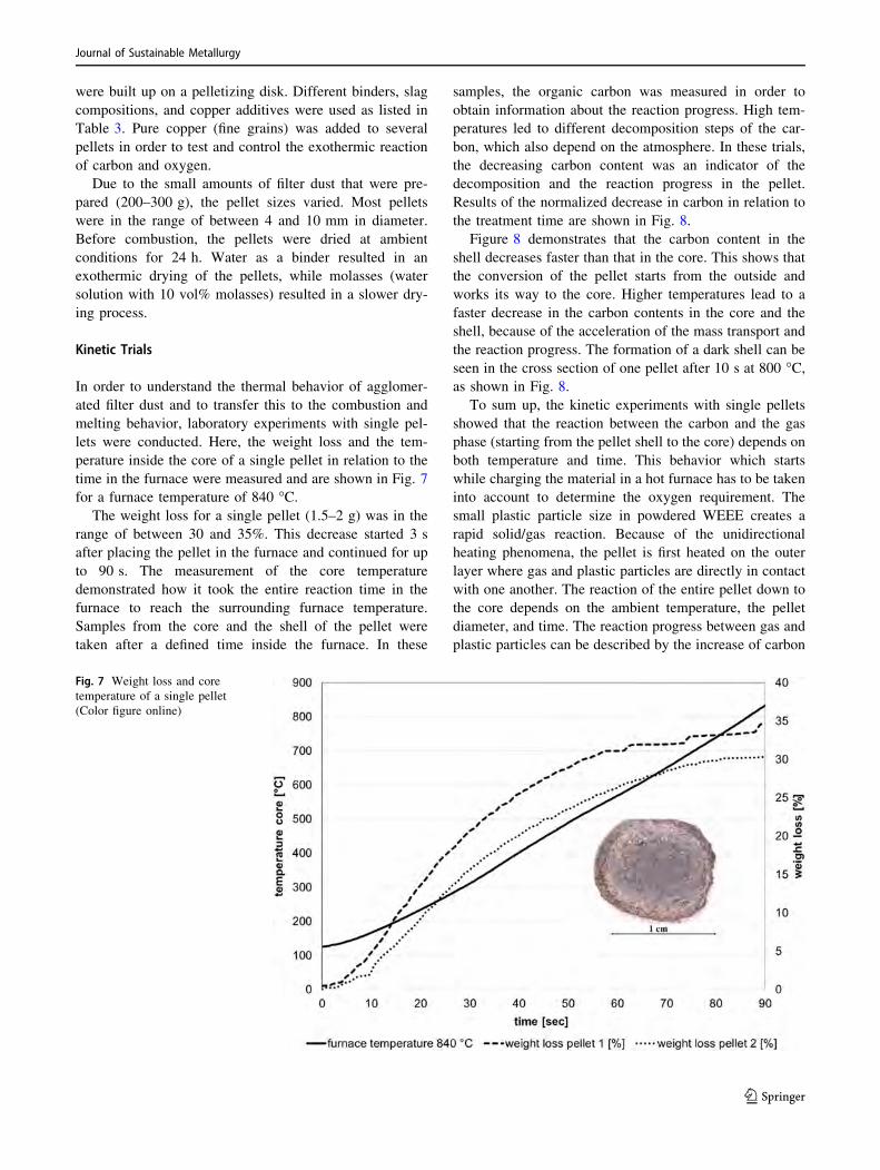
Kinetic Trials
In order to understand the thermal behavior of agglomer-
ated filter dust and to transfer this to the combustion and
melting behavior, laboratory experiments with single pel-
lets were conducted. Here, the weight loss and the tem-
perature inside the core of a single pellet in relation to the
time in the furnace were measured and are shown in Fig. 7
for a furnace temperature of 840 �C.The weight loss for a single pellet (1.5–2 g) was in the
range of between 30 and 35%. This decrease started 3 s
after placing the pellet in the furnace and continued for up
to 90 s. The measurement of the core temperature
demonstrated how it took the entire reaction time in the
furnace to reach the surrounding furnace temperature.
Samples from the core and the shell of the pellet were
taken after a defined time inside the furnace. In these
samples, the organic carbon was measured in order to
obtain information about the reaction progress. High tem-
peratures led to different decomposition steps of the car-
bon, which also depend on the atmosphere. In these trials,
the decreasing carbon content was an indicator of the
decomposition and the reaction progress in the pellet.
Results of the normalized decrease in carbon in relation to
the treatment time are shown in Fig. 8.
Figure 8 demonstrates that the carbon content in the
shell decreases faster than that in the core. This shows that
the conversion of the pellet starts from the outside and
works its way to the core. Higher temperatures lead to a
faster decrease in the carbon contents in the core and the
shell, because of the acceleration of the mass transport and
the reaction progress. The formation of a dark shell can be
seen in the cross section of one pellet after 10 s at 800 �C,as shown in Fig. 8.
To sum up, the kinetic experiments with single pellets
showed that the reaction between the carbon and the gas
phase (starting from the pellet shell to the core) depends on
both temperature and time. This behavior which starts
while charging the material in a hot furnace has to be taken
into account to determine the oxygen requirement. The
small plastic particle size in powdered WEEE creates a
rapid solid/gas reaction. Because of the unidirectional
heating phenomena, the pellet is first heated on the outer
layer where gas and plastic particles are directly in contact
with one another. The reaction of the entire pellet down to
the core depends on the ambient temperature, the pellet
diameter, and time. The reaction progress between gas and
plastic particles can be described by the increase of carbon
Fig. 7 Weight loss and core
temperature of a single pellet
(Color figure online)
Journal of Sustainable Metallurgy
123

loss. The carbon content decreases with the reaction time,
whereby the decrease in the shell is faster compared to the
core. Increasing the temperature influences the carbon loss
directly to a faster reaction. The reaction time to the core is
also shown with the temperature measurement inside the
core. These phenomena have a direct influence on the
reaction with oxygen and the resulting oxygen amount for
the combustion of the organic content. In further research,
the mechanism of decomposition and gas–solid reactions
will be analyzed in more detail.
Melting Experiments
The laboratory-scale melting experiments were carried out
in a resistance furnace. Pellets made of filter dust and the
experimental setup can be seen in Fig. 9. Before charging
the material, the crucible was heated to 900 �C to ensure
that there was sufficient activation energy for the com-
bustion of the organic compounds. A constant oxygen flow
ranging between 10 and 15 L/min was injected into the
crucible through a ceramic lance. The pellets were charged
in batches in order to prevent the lance from becoming
blocked. The temperature was measured between the two
crucibles, in the off-gas tube and in the crucible before the
material was charged. The off-gas composition (CO, CO2,
O2) was also measured.
The pellets used were stable while they were charged
into the crucible and did not show any signs of spalling.
After charging, the start of the combustion was visible after
3 s. The resulting liquid phase could only be detected in the
parts of the crucible, where the oxygen lance was blowing
directly onto the material. After complete combustion, the
reaction crucible was taken out of the combustion furnace
and placed into another resistance furnace at
1300–1400 �C for one hour to hold the system at the cal-
culated equilibrium conditions. Afterward, the crucible was
taken out of the furnace afterward and cooled in ambient
air, crushed, and its content manually separated into slag
and metal. Samples of slag were analyzed using XRF
analysis, while metal samples were analyzed using spark
spectrometry.
Results and Discussion for Laboratory-ScaleExperiments
To investigate the requirements of the pelletizing step and
the optimization of the filter dust composition, combustion
experiments with ‘‘pure’’, nonpelletized filter dust were
conducted. In these experiments, it was impossible to
achieve a clear separation between the metal and slag
phase, and only the formation of small metal droplets on
the surface of the material was observed (see Fig. 10).
Because of the turbulent off-gas generation (combustion
combined with oxygen blow), high material losses[ 50%
occurred. In summary, more oxygen was required to
combust the entire organic fraction compared to that in the
theoretical calculation. The actual oxygen amount required
for a combustion of the entire organic content was 39–43 L
oxygen per 100 g of filter dust.
The melting behavior of the pellets depends strongly on
the composed mixture. For some mixtures, a clear sepa-
ration between metal and slag was achieved. In other cases,
high melt viscosity led to an incomplete combustion of the
material and to the formation of a solid top layer.
Fig. 8 Normalized losses of
carbon in the core and the shell
after defined treatment times at
different temperatures (Color
figure online)
Journal of Sustainable Metallurgy
123

The composition of the metal phase mainly consisted of
Cu, Pb, Zn, Sn, and Sb. Other detected elements were
precious metals such as silver and gold. The copper amount
was between 74 and 96 wt% copper. In experiments with
the addition of coper, a higher amount of copper in the
metal phase was analyzed. For experiments with the
addition of Na2O up to 8.5 wt% lead was found in the
metal phase (mixture 4–6), whereas the lead content in
mixture 7–12 was below 1 wt% in the metal phase. Weight
loss in the melting experiments was between 30 and
35 wt%, which is in line with the weight loss experiments
for single pellets (see ‘‘Kinetic trials’’).
A comparison between the modeled and analyzed metal
compositions for selected mixtures 4–6 is shown in Fig. 11.
In general, the modeled FactSageTM composition is very
much in line with the produced metal phases. For mixture
4, a combination of 10% Na2O, filter dust and molasses as
the binder was investigated experimentally. The calculated
melting point of the slag phase was assumed to be around
1300 �C. The oxygen amount required to achieve a clear
separation between metal and slag was 39–42 L per 100 g
of filter dust. In experiments with mixture 4, around 6%
metal and 50% slag were produced (? material losses in
Fig. 9 Pellets made of filter dust (left) and the experimental setup for combustion experiments (right) (Color figure online)
Fig. 10 Metal droplets on the surface after combustion experiments with pure filter dust (Color figure online)
Fig. 11 A comparison between the actual and modeled metal
compositions (Color figure online)
Journal of Sustainable Metallurgy
123

off-gas and combustion weight loss). The metal phase
contained a higher copper amount (84 wt%) than calcu-
lated (79 wt%). Instead, the amount of tin was significantly
lower than calculated, which also applies to all metal cal-
culations shown. Due to the fact that the actual oxygen
amount was higher than the one calculated, a selective
oxidation of a higher amount of metal was possible (see
Fig. 6). This supports the fact that the actual iron amount in
the metal phase was lower than those calculated in mix-
tures 4 and 6. The metal phase in experiment 5 contained
less copper (74.8% as opposed to 81.2%) than modeled in
contrast to the iron amount that was much higher (8.5% as
opposed to 4.9%). This can be justified by a segregation of
the melt into a copper-rich phase and an iron-rich phase.
The equilibrium modeling only predicted segregation in the
metal phases for oxygen additions, which was significantly
lower in comparison to the actual oxygen addition for
mixture 5. This shows that it was not possible to achieve
the equilibrium between the metal and the slag phase in the
laboratory-scale experiments. The small scale also caused
metal losses in the slag phase, which will be optimized in
the scale-up experiments (Comment 1).
For precious metals like gold and silver, it was possible
to achieve recovery rates that were significantly above
100%. This proved that the input material was rather
inhomogeneous and contained more precious metals than
those estimated in the calculations. Antimony was found in
the produced metal phases, which was not taken into
account for the FactSageTM calculation. The model will be
extended due to this result in future studies.
A comparison between the actual and the modeled slag
compositions for selected experiments is shown in Fig. 12.
The chemical slag analysis was normalized to 100 wt%.
Only the main and relevant oxides were shown with an
individual color. ZnO, PbO, NiO, SnO, and MgO were
summarized (rest). Generally speaking, the calculated slag
composition (FactSageTM) showed a good correlation with
the analyzed slag composition, especially for the amounts
of SiO2, Na2O, and CaO. The actual amount of Al2O3 was
smaller than the ones calculated for all experiments. This
observation implies that the content of alumina in the raw
material was less than that assumed. In contrast, the con-
tents of iron oxides and copper oxide were higher than
those calculated. Analysis showed a copper content of
between 1.7 and 4.4 wt% (CuO) in the slag, whereas the
modeled amount was\ 0.3 wt%. One possible explanation
for this is that the material needs a longer time to react and
a higher oxygen amount to combust than that assumed. The
higher input of oxygen and the small scale of the trials bear
the risk of copper oxidation. Higher recoveries of metals
such as Pb, Zn, and Sn in the metal phase cannot be
achieved because of the small material input and the rel-
atively high oxygen amount. The influences of metal oxi-
des on the slag melting point and its viscosity must
therefore be taken into account in further calculations
(Comment 3).
To sum up all results from the laboratory-scale experi-
ments, it is absolutely necessary to optimize the high
melting filter dust in order to achieve a metal and slag
separation. In the small-scale experiment, an addition of
10% Na2O continuously showed the best results. Calcu-
lating the melting point and slag/metal composition with
FactSageTM showed a good correlation with the chemical
analysis. However, challenges for modeling the melting
behavior in laboratory-scale trials with FactSageTM are:
– A significantly higher amount of oxygen due to the
kinetics of the reaction of oxygen and carbon in the
pellet (see ‘‘Kinetic trials’’) and the unknown oxygen
efficiency on the laboratory scale.
– Oversimplification of the actual input material for
modeling. Due to this fact, several elements, for
example, antimony are not taken into account.
– Due to differences in density and particle size, segre-
gation during storage can occur. The input material is
mixed for a defined time before the experiments, but
inhomogeneity cannot be ruled out, which has a great
influence because of the small scale.
– FactSageTM models are calculations in the equilibrium
where kinetics are not taken into account. This
influences, for example, the calculations for phase
distribution and oxygen requirements.
Scaled-Up Experiments
The laboratory experiments showed the feasibility and
potential metal yields by melting WEEE powders. In the
next step, the effects of e-waste powders and fines on the
slag phase on the small industrial scale (0.5 m3 meltFig. 12 A comparison between the actual and modeled slag compo-
sitions (Color figure online)
Journal of Sustainable Metallurgy
123

volume) were investigated in order to reduce any side
effects and to compare the simulated FactSageTM results
with the actual melting experiments. Therefore, finely
grinded PCBs were injected into a synthetic slag phase at
1300 �C, the starting temperature. Furthermore, it was
tested as to whether a foamy slag can be achieved. The
general experimental setup is shown in Fig. 13.
The experiments were conducted in a top-blown rotary
converter (TBRC) at the IME Institute in Aachen as shown
in Fig. 14. The powders and fines were injected into the
slag phase near the metal–slag boundary through the main
injector. A second injector was optional and not in use for
the main process. It can, however, be added in special cases
when fluxing is required. The experiment was conducted
with an initial molten slag bath formed by a SiO2, Al2O3,
and CaO composition, chosen so that the lowest possible
liquidus temperature was achieved.
After the slag was completely molten, the powders were
injected into the molten slag phase. The mass flow of
injected WEEE powders was adjusted according to the
calculated energy requirement for an autothermic melting
process between 1350 �C and 1450 �C and was based on
the calorific value of the previously measured carbon
content of 30 wt%. Based on the results of the laboratory
trials, the simultaneously injected amount of oxygen was
slightly increased to the calculated value of 320 L O2 per
kg powder and later adjusted so that the organics could be
completely combusted. After 800 kg of material had been
continuously injected into the slag phase and 30 min of
holding time had passed at 1450 �C, both, slag and metal
phases, were tapped. The produced metal settled at the
bottom of the ladle and could be easily separated from the
slag after cooling (Fig. 15). Finally, several samples of
each phase were taken and analyzed.
Results from the Scaled-Up Experiments
Combustion of Organics Depending on the Oxygen Supply
The combustion of the WEEE powders was executed so
that nearly no fumes in the off-gas stream were visible. The
gas temperature and composition especially in terms of
CO, H2, and NOx were continuously measured. In Fig. 16,
a characteristic extract of the measured data is shown. Here
the actual oxygen amount per kg of powder is shown for
two cases: on the one hand, the calculated 320 l oxygen per
kg, and on the other hand, the actual oxygen consumption
per kg of the injected material. All values are in relation to
the actual material mass flow. In addition to the two oxy-
gen consumption rates, the resulting temperature of the off-
gas stream is also shown. Primarily, three different inter-
vals can be identified (based on the calculated stoichio-
metric oxygen requirement):
(I) Low oxygen input: The actual injected oxygen
amount is way below the calculated oxygen
requirement.
(II) Equal or slightly higher oxygen input than the
stoichiometric calculated (incl. 25% O2 addition).
(III) High oxygen input: The actual injected oxygen
amount is well beyond the calculated oxygen
requirement.
Interval 1 is exemplary for combustion processes with a
lack of oxygen. A first indicator therefore is the increasing
Fig. 13 Schematic process of WEEE powder injection into the slag phase
Journal of Sustainable Metallurgy
123

off-gas temperature exceeding the material mass flow
caused temperature change due to strong post-combustion
processes in the off-gas stream. A second and very strong
indicator can be seen in Fig. 17. Here the CO, H2, and NOx
formation is shown for the same time interval as that shown
in Fig. 16. The area of phase 1 contains various and very
high CO peaks accompanied by visual and distinct H2
peaks. This results from a lack of sufficient oxygen for
combustion. Hence, only CO can be formed. The lack of
oxygen is so high that pure H2 was formed but not post-
combusted.
Interval (2b) shows an area of sufficient oxygen
requirement, and in the case of interval (2a), even with a
small excess of oxygen. These intervals are characterized
by a stable temperature and very low CO amounts. In the
interval (2b), the oxygen demand nearly equals the 320 L
per kg with less oxygen excess than that in (2a). Here a CO
formation below 50 ppm can be identified with a few peaks
slightly exceeding the 50 ppm value. In the case of H2 in
both intervals (2a) as well as (2b), no relevant peaks are
visible. By comparing the two intervals, it can be said that
the CO as well as the H2 amounts in the off-gas are lower
with a slightly increased oxygen value.
The same result can be seen in interval 3 where the
injected oxygen strongly exceeds the calculated amount. In
terms of CO and H2 formation, no significant change
compared to interval (2a) can be seen. Only a strong
temperature decrease in the off-gas stream is apparent. The
strong decrease results, on the one hand, from a decreased
material flow and, on the other hand, from gas excess and
reduced post-combustion processes in the off-gas stream.
By comparing all intervals, it is evident that interval 1 is
not suitable for the melting process due to the high pollu-
tion of the off-gas streams. Moreover, interval 3 is not
suitable; even though it shows good off-gas values, the
high oxygen content has no significant influence and
inevitably leads to an oxidization and loss of valuable
metals. The best results were achieved with equal or
Fig. 14 TBRC with lances for
injecting WEEE powders and
oxygen (Color figure online)
Fig. 15 Left: Injecting powder
into the slag phase; right:
Cooled slag and metal block
(Color figure online)
Journal of Sustainable Metallurgy
123

slightly increased oxygen values compared to that for the
previously calculated 320 L. Considering only interval 2
process phases, 400 L of oxygen per kg of powder were
injected parallel to the material. Compared to the previ-
ously calculated value of 320 L per kg of injected material,
the actual oxygen requirement appears to be 25% higher
Fig. 16 Comparison of the actual and calculated oxygen consumptions depending on mass flow (Color figure online)
Fig. 17 CO, H2, and NOX concentrations in off-gas (Color figure online)
Journal of Sustainable Metallurgy
123

than that assumed. This can be explained by the reaction
rate of the oxygen that may not react even though it is
injected into the slag because all of the surrounding ele-
ments have already been oxidized. The reaction rate under
scaled-up conditions seems to be less than that experienced
under the laboratory experiments. In terms of NOx for-
mation, Fig. 17 shows that the average value lies below
300 ppm and, in most cases, even below 200 ppm. Over
the entire process, values below 200 ppm were most
common. Compared to the values produced by the natural
gas burner between 800 and 1100 ppm NOx depending on
operation mode, the values of the autothermal WEEE-
powder melting were 75–80% less.
Liquidus Temperature and Viscosity of the Slag Phase
During the entire experiment, the slag was completely
molten at temperatures of approximately 1400 �C and
showed a low viscosity with no significant changes even
though material was continuously injected. Hence, no
fluxes were added to the process. It should be mentioned
that the evaluation of the slag’s viscosity during the process
could only be carried out visually and on the basis of
experience, due to the high turbulences in the furnace and
the slag’s foaminess, which exclude all calculation and
modeling opportunities. The foaminess of the slag partly
resulted from the injected nitrogen and oxygen but mostly
from CO/CO2 bubbles that formed in the slag phase. The
foaminess was not as strong as expected. This can be
explained by the material flow compared to the reactor
size. For a good and strong foaming of the slag, greater
carbon-rich material is required in the process. In this
particular case, this was impossible due to the already
relatively high energy levels at these material input rates.
In terms of liquidus temperature, it appeared that the
entire slag phase was completely molten at these temper-
atures without adding any additives. This experimentally
observed completely molten slag phase at approximately
1400–1450 �C in contrast to the calculated liquidus
temperatures of both the initial material composition as
well as the final slag composition, shown in Table 4, as
1495 and 1514 �C, respectively. Both liquidus tempera-
tures are above the temperature conditions in the furnace.
The great deviation between the measured temperature
in the furnace with a molten slag and the theoretically
calculated temperature for a complete liquid slag phase
with FactSageTM can be explained by an error in temper-
ature measurement even though this was double checked
by two independent measurement systems (pyrometer and
thermocouple). Another possibility could be an error in
FactSageTM calculations due to the exclusion of metallic
oxides with a very low percentage of weight although
metal oxides such as MgO and TiO2 were experimentally
added to the calculation. However, the liquidus tempera-
ture could only be decreased to 1475 �C which is still
above the average furnace temperature. The most realistic
explanation for the observed effect is a possible high metal
content (Cu) in the slag phase during the process, which
could not be measured in the cooled slag due to efficient
metal settling. A higher Cu content in the slag phase than
the measured would lead to significant changes in liquidus
temperatures even below 1400 �C and explain the low
viscosity and liquidus temperature. To validate this
assumption, further tests are necessary with continuous
slag sampling.
Products and Distribution of Metals
The analysis of the products shows that 277 kg of slag and
96 kg of metal phase are produced with 670 kg of input
material. Hence, 56% of the injected material is trans-
formed into metal and slag, whereas 44% is lost to filter
dust or the off-gas. The loss within the scaled-up experi-
ments appears to be higher compared to the laboratory
trials (30–35% loss) and can be explained by the com-
bustion of the organic content, which has a higher per-
centage in the injected powder than that in the dust.
Furthermore, the discharge of volatile components like Zn
is slightly increased at scaled-up experiments. In total, the
44% of material loss is in line with the aforementioned
assumption of 40–45 wt% of organics in the material. The
detailed analysis of the produced metal and slag phases
shows that, on the one hand, the metals of interest were
successfully recovered in a metal phase with relatively high
recovery rates and that, on the other hand, iron was
Table 4 Composition and liquidus temperatures
Wt% SiO2 Al2O3 CaO Fe2O3 Tliq [�C]
Powder 42.6 28.8 18.5 10.1 1495
Slag 38.2 33.8 20.4 7.6 1514
Table 5 Metal composition and
distributionWt% Cu Ni Fe Pb Sn Ag Mass (kg)
Slag 3.32 0.245 3.92 0.33 1.09 – 277
Metal 92.98 0.994 0.012 0.24 4.88 0.21 96
Distribution coefficient 0.036 0.247 326 1.375 0.223 \ 0.001
Journal of Sustainable Metallurgy
123

selectively oxidized. Table 5 illustrates that nearly 97% of
Cu and over 80% of Sn and Ni were recovered. The rest
was oxidized and caught in the slag. In terms of iron, nearly
99% was selectively oxidized and transferred to the slag
phase.
Conclusion and Open Issues
Laboratory-scale experiments show that it is essentially
necessary to optimize high melting scrap types with addi-
tives in order to achieve a distinct metal-and-slag separa-
tion. To avoid extensive mass losses and to obtain a
reaction of the material in the targeted reaction zone, it is
necessary to include a pelletizing step or to blow the
material in the slag phase. By adding different additives, it
is possible to achieve the formation of the slag phase and to
avoid the formation of solid mineral phases. The actual
oxygen amount required to achieve this separation and to
make the entire organic content combustible is approxi-
mately 30% higher. One reason for this higher amount
required is the amount of oxygen lost to the off-gas system.
Furthermore, not only the amount of carbon but also the
kinetics for the reaction between oxygen and carbon have
to be taken into account, because of the unidirectional
heating phenomena from the pellet shell to the core.
Studies on the decomposition and gas–solid reactions of
carburized pellets will be investigated in future research.
Generally speaking, the phase equilibrium modeling agrees
with the practical results. Differences occur because the
input material is not homogeneous, because of the
oversimplified model of the material and because the
equilibrium, as modeled in FactSageTM, was not achieved.
The scale up showed that an autothermal melting pro-
cess with powdered e-waste material is possible without
any restriction even when the additives are not included.
The experimentally determined oxygen demand validated
the results of the lab trails demonstrating that an excess of
oxygen is necessary to combust the organics efficiently
without strong pollution of the off-gas stream. Under
technical conditions, the oxygen excess is slightly
decreased to 25% (compared to 30% excess in laboratory
experiments), and will be less under even more extreme
melting conditions. The injected gases and the CO/CO2
that were produced, foamed the slag but not as much as
was expected. With the increasing material flow, the slag’s
foaming will also increase due to a greater production of
CO/CO2, which is the main driver for slag’s foaming. The
results of the melting trial show that 55% of the injected
material is recovered in two product phases. Precious
metals can be recovered with very high recovery rates of
97% for Cu, and more than 80% for Sn and for Ni. The low
Fe content in the metal phase shows that it is possible to
selectively oxidize iron and transfer it to the mineral phase.
Figure 18 illustrates a comparison of the metal distri-
bution coefficients between laboratory and scaled-up
experiments. Even though the input materials are different,
the results show very similar distribution tendencies except
for iron and lead. This can be explained by a greater oxi-
dizing atmosphere during the scaled-up experiments and a
faster oxygen–material reaction due to the increased reac-
tion surfaces compared to that of the pelletized material.
Despite the atmospheric influences on iron and lead,
Fig. 18 Distribution coefficients of metals in the laboratory-scale and scaled-up experiments (Color figure online)
Journal of Sustainable Metallurgy
123

valuable metals such as copper, nickel, and tin are col-
lected in a metal phase with high recovery rates but with a
slightly decreased metal distribution coefficient for the
metal phase compared to the laboratory experiments.
The experiments show that it is possible to introduce
powdered e-waste fractions and dusts into a molten slag
phase. Further investigations should be conducted on
gas/solid reactions and the autogenous combination of
dusts with other waste fractions. In terms of organic
combustion and selective oxidation, the oxygen input has
to be optimized and precisely adjusted to the mass flow
according to the experimental results. Furthermore, studies
on the copper content during melting and its development
have to be carried out in order to explain and match the
observed effects with the simulation results.
Acknowledgments We offer our special thanks to the Stein Injection
Technology GmbH for providing the injection equipment and the
knowhow. This project is promoted by the federal Ministry for
Economy and Energy according to a decision of the German federal
parliament.
References
1. Balde C et al (2015) The global E-waste monitor—2014. United
Nations University
2. Rhamdhani M et al (2014) Metal extraction processes for elec-
tronic waste and existing industrial routes: a review and aus-
tralian perspective. Resources 3(1):152–179
3. Veit H, Bernardes A (2015) Electronic waste: recycling tech-
niques. Springer, Berlin
4. Bartos R et al (2015) Stahlfibel. Verlag Stahleinsen GmbH
5. Wang S et al (2003) Verhalten der Reduktion und Volu-
menanderung von selbstreduzierenden Pellets mit DSD und
Kohle als Reduktionsmittel, 18. Aachener Stahlkolloqium,
pp 29–41
6. Kowitwarangkul P (2014) Reduction behavior of self-reducing
pellet (SRP) for low height blast furnace. Steel Res Int
85(11):1501–1509
7. Nascimiento RC et al (1999) Kinetics and catastrophic swelling
during reduction of iron ore in carbon bearing pellets. Ironmak
Steelmak 26(3):182–186
8. Lahiri AK et al (2004) Foaminess of slag: cause and control. In:
VII international conference on molten slags fluxes and salts. The
South African Institute of Mining and Metallurgy, Johannesburg
9. Liukkonen M et al (2012) A compilation of slag foaming phe-
nomenon research theoretical studies, industrial experiments and
modelling. VTT Technology 63
10. Merz M et al (2006) New slag foaming experiences with high-
chromium steels. Stahl und Eisen 126(1):49–53
11. Shaw D (1996) Recycling of oily millscale and EAF-baghouse
dust by re-injection into an EAF using the carbofer process.
Working party on steel, seminar on the processing, utilization and
disposal of waste in the steel industry, Ungarn
12. Liebman M (2000) The current status of electric arc furnace dust
recycling in North America, in Recycling of metals and engi-
neered materials. Wiley, Hoboken
13. Kruger J et al (1998) Einsatz von sekundaren, zink- und blei-
haltigen Materialien bei der Sinterrostung im Imperial Smelting
Prozess. Rohstofftechnik im Wandel, Aachener Umwelttage der
Fakultat fur Bergbau, Huttenwesen und Geowissenschaften
14. Wang R et al (2014) Recycling of non-metallic fractions from
waste electrical and electronic equipment (WEEE): a review.
Elsevier, Amsterdam
15. Hageluken C (2006) Improving metal returns and eco-efficiency
in electronics recycling—a holistic approach for interface opti-
mization between pre-processing and integrated metals smelting
and refining. In: Proceedings of the 2006 IEEE international
conference
16. Rotter V et al (2014) Anlagenbilanzierung als Bewertungsin-
strument fur eine Qualitats-recycling von Elektroaltgeraten.
Recycling und Rohstoffe 7:191–203
17. Martens H (2011) Recycling von Elektro-und Elektronikalt-
geraten. In: Recyclingtechnik, pp 273–301
18. Bigum M et al (2012) Metal recovery from high-grade WEEE: a
life cycle assessment. J Hazard Mater 207–208:8–14
19. Chancerel P et al (2009) Edelmetallruckgewinnung aus Elektro-
und Elektronikaltgeraten durch Aufbereitung. Mull und Abfall
2:78–82
20. Wang F et al (2015) Mineralogical analysis of dust collected from
typical recycling line of waste printed circuit boards. Waste
Manag 43:434–441
21. Espinosa D et al (2015) Electronic waste: recycling techniques
(chapter 8). Springer, Berlin
22. Shuey SA et al (2006) Pyrometallurgical processing of electronic
waste. In: SME Annual Meeting
23. Ogunniyi IO et al (2009) Chemical composition and liberation
characterization of printed circuit board comminution fines for
beneficiation investigations. Waste Manag 29(7):2140–2146
Journal of Sustainable Metallurgy
123