metallurgical characterisation of a historical metal tie
TRANSCRIPT

Construction and Building Materials 226 (2019) 888–898
Contents lists available at ScienceDirect
Construction and Building Materials
journal homepage: www.elsevier .com/locate /conbui ldmat
Metallurgical characterisation of a historical metal tie-rod from MilanCathedral
https://doi.org/10.1016/j.conbuildmat.2019.07.2720950-0618/� 2019 Elsevier Ltd. All rights reserved.
⇑ Corresponding author.E-mail addresses: [email protected] (M. Bellanova), andrea.
[email protected] (A. Baggioli), [email protected] (B. Rivolta), [email protected] (R. Felicetti).
Mariagrazia Bellanova a,⇑, Andrea Baggioli b, Barbara Rivolta c, Roberto Felicetti a
aDepartment of Civil and Environmental Engineering, Politecnico di Milano, Piazza Leonardo da Vinci, 32, 20133 Milano, Italyb Polo Territoriale di Lecco, Politecnico di Milano, Via Gaetano Previati, 1/c, 23900 Lecco, ItalycDipartimento di Meccanica, Politecnico di Milano, Via La Masa 1, 20156 Milano, Italy
h i g h l i g h t s
� The metallurgical features of a hand-made tie were studied to infer the causes of failure.� The material was found to be extremely heterogeneous in terms of matrix, inclusions and defects.� Metallurgical evidence suggests that failure occurred along forged welds.� More ductile behaviour is associated with a mainly ferritic matrix with iron-rich bulky-shape dendritic slag inclusions.� Sudden variation of microstructure due to the forged weld can be seen across the visible crack.
a r t i c l e i n f o
Article history:Received 12 February 2019Received in revised form 3 July 2019Accepted 22 July 2019
Keywords:Tie-rodWrought-ironMilan cathedralFailure analysisMetallurgical characterizationArchaeometallurgy
a b s t r a c t
One tie-rod from Milan Cathedral (15th century) recently broke in a defective cross-section. In order toinfer the causes of failure, a metallurgical characterisation was performed, the results of which are dis-cussed here. First, a visual inspection of the specimen was performed. Next, the fracture surface was anal-ysed using a Scanning Electron Microscope (SEM) combined with Energy Dispersive X-Ray Spectrometry(EDXS) to detect the failure modes involved. A cross-section close to the failure surface was investigatedby means of Stereoscopy, Light Optical Microscopy (LOM), SEM and EDXS in order to identify themicrostructural compounds and characterise the slag inclusions. Vickers and Rockwell hardness testswere also carried out to correlate microstructural observations with mechanical properties. A strong rela-tionship between failure and defects due to forging was observed, which is a particularly noteworthyresult with regard to the representativeness of laboratory tests and the viability of in-situ inspection.
� 2019 Elsevier Ltd. All rights reserved.
1. Introduction
Historical wrought iron can be considered a completely differ-ent material from modern steel, despite both of them being iron-carbon alloys. Regarding iron-working technology, in the past notheoretical knowledge was available. Artisans learned to produceartefacts in workshops in accordance with the best practices avail-able at the time. The quality of the products strongly depended onthe master’s ability. Therefore, workpieces from the same periodmay differ greatly from one another. Sometimes the main materialproperties may vary even within the same element.
Ore reduction and forging are probably the most crucial stages.Mechanical properties, homogeneity and surface features arehighly dependent on the smelting temperature and reducingpower of the furnace. In the history of metallurgy, two ore reduc-tion methods can be distinguished: the direct and the indirectmethod, which have been extensively discussed by many authors[1,2]. The direct method is the most ancient technique. The reac-tion product is a spongy mass called bloom, which is a highlyheterogeneous mixture of solid iron usually characterised by alarge number of non-metallic Slag Inclusions (SIs), local porosities,and larger voids. The indirect method was introduced in the 14thcentury. The term refers to the reduction of ore into pig iron inthe blast furnaces. This pig iron could be used for casting orreheated in finery forges. As many authors have pointed out, themetallurgical analysis of SIs can provide interesting informationabout the reduction method used [3,4]. With regard to the forgingphase, macro discontinuities and rough surfaces resulted from

M. Bellanova et al. / Construction and Building Materials 226 (2019) 888–898 889
handwork. Typical macro-defects of tie-rods are forged welds.Wrought iron elements of considerable size (such as strengtheningbars) were usually obtained by joining several pieces [5,6,7]. Theedges of the bars to join were heated to a temperature below themelting point and then hammered together to create an integral,homogeneous joint. Before welding, the edges were shaped inorder to guarantee the largest contact area between the two pieces,more effective pressing force and hence a better connection [8,9].Based on these premises, defects at the micro- and meso-scale thatare inherent to the reduction process can be identified in historicalmetal components, as can flaws at the macro scale due to forging.Both of them influence the mechanical behaviour of the elementand hence its structural performance.
Tie-rods from Milan Cathedral represent an extremely interest-ing example of historical metallic components. The building of thecathedral on a former Christian complex started in 1386 from theapses and the choir in the east. It continued through the edificationof the transept with the tiburio and dome, which was followed bythe erection of the five naves and the spires from east to west. TheCathedral was completed at the beginning of the 19th century withthe construction of the façade [10]. Compared to tie-rods in otherhistorical buildings, the structural elements examined have signif-icantly larger cross-sections: the average dimensions are83x55mm2. Their length ranges from 5.1 m to 16.4 m dependingon the nave. Tie-rods were placed from the beginning of the con-struction at the springer of every arch and hence most of themhave been active for over 500 years. The structural system of thechurch shows some very interesting peculiarities making evenmore crucial the structural role of tie-rods [11]. Typically, horizon-tal thrusts are balanced by many bearing elements [12]. In MilanCathedral, the main elements devoted to this purpose were thetie-rods and the transversal masonry walls above the vaults. More-over, over the centuries the loads have continuously changed dueto both human and environmental factors, causing a redistributionof the loads through the structure [13,14,15].
In May 2009 the deformation monitoring system workinginside the cathedral recorded an anomalous verticality variationin pillar 88 compared with the trend of the previous years [16].Examination of the area concerned revealed the failure of the tie-rod connecting piers 58 and 88, which was then substituted witha modern steel bar. This event showed the need to perform a broadmultidisciplinary study on these elements in order to infer the pos-sible causes of failure. Although microclimate monitoring revealedthat during the year relative humidity sometimes exceeds the lim-its set by the current codes for the conservation of metallic compo-nents, favouring the occurrence of corrosion [17], evidence of thefailure suggest a collapse due to mechanical reasons. The studytherefore had three main focuses: a) estimation of the actual ten-sile stress of the active elements; b) identification of the mostdetrimental defects through the use of Non Destructive Techniques(NDTs); c) material characterisation.
The dynamic identification method proposed in [18] was imple-mented in situ on 112 tie-rods in order to estimate their actualstate of stress. This provided interesting results, with stress valuesin the range of 0–150 N/mm2 [19]. However, this approach canhardly allow to detect the presence of dominant defects, whichgovern the actual load capacity of the elements. Forged welds areamong the most detrimental ones as they constitute discontinu-ities which span the whole cross-section. The critical nature offorged welds in structural terms makes their identification andmonitoring paramount. As no methods specifically designed forthis purpose are currently available, several NDTs commonlyadopted for the inspection of modern metals were studied in orderto evaluate the potential for extending them to the field of culturalheritage [20]. By adapting eddy current testing to this unconven-tional application, based on a customised probe, it was possible
to identify forged welds, which are the dominant defects of Milancathedral tie-rods [21].
With regard to mechanical properties, a first campaign was per-formed using standard tensile tests according to EN ISO 6892-1 oneight samples machined from the broken tie-rod [19]. Resultsshowed a very high standard deviation due to the presence ofmany defects. Specifically, yield stress, tensile strength and elasticmodulus were 142 ± 60 MPa, 199 ± 111 MPa and 206 ± 45 GPa,respectively. For this reason, a mechanical characterisation basedon fracture properties of the material was considered more reliableand hence Elasto Plastic crack initiation testing was performedaccording to ASTM E1820-17 on 13 samples machined from boththe base material and the material close to a forged weld [20].The results shed light on the structurally critical nature of forgedwelds: fracture toughness at these locations was one order of mag-nitude lower than the fracture toughness of the base material. Den-sity was measured using the hydrostatic weighing method,yielding a result of 7792 kg/m3. Since most of the techniques forcrack detection are electromagnetic methods, the electrical andmagnetic properties of the base material were identified as well.The electrical conductivity (q) was found to be (9.1 ± 0.9) � 106S/m, while the magnetic hysteresis cycles showed a residual induc-tion and coercive force of about 0.859 T and 889.5 A/m, respec-tively [21].
The studies discussed here were conducted within the above-mentioned broader multidisciplinary investigation concerningthe replaced tie-rod from Milan Cathedral. The aim was to charac-terise the material properties and to study the reason for failures inorder to identify any potential structurally critical features. To thisend, failure modes were estimated, and microstructural com-pounds, types of inclusions, incidence of voids and mechanicalproperties were studied in detail since they may provide insightsof fundamental interest.
2. Material and methods
When ancient buildings are analysed, NDTs are usually pre-ferred. In the case at issue, it was possible to perform severalDestructive Tests (DTs) because the broken tie-rod removed in2009 was made available. The studies focused on the portion ofthe element close to the failure surface. More precisely, the frac-ture surfaces (samples A1 and A2) and the section adjacent to sam-ple A1 (sample B) were analysed in depth in order to infer thepossible causes of failure and to characterise the material. Thelocation of the samples analysed is shown in Fig. 1. Unfortunately,the actual tensile stress of the element before collapse is unknownas extensive dynamic tests were performed later. However, it isinteresting to note that the three southward tie-rods located alongthe same transverse section of the cathedral showed very high ten-sile stress values (90–110 MPa).
The different techniques listed belowwere employed in an inte-grated manner to achieve reliable results.
- Unaided Visual inspection (VI): although it must be combinedwith more detailed analyses, unaided VI enables preliminaryhypotheses on failure modes and material features to be made.
- Stereo Microscopy (SM): preliminary observations were carriedout using a NIKON SM Z2800 stereoscope. This made it possibleto detect many kinds of inclusions and porosities, to analyse thearea close to the crack and to identify the most interestingregions to inspect.
- Light Optical Microscopy (LOM): it was mainly adopted to anal-yse microstructures and grain size, identify defects, and providean initial description of the SIs. A LEICA MDR light opticalmicroscope was used.
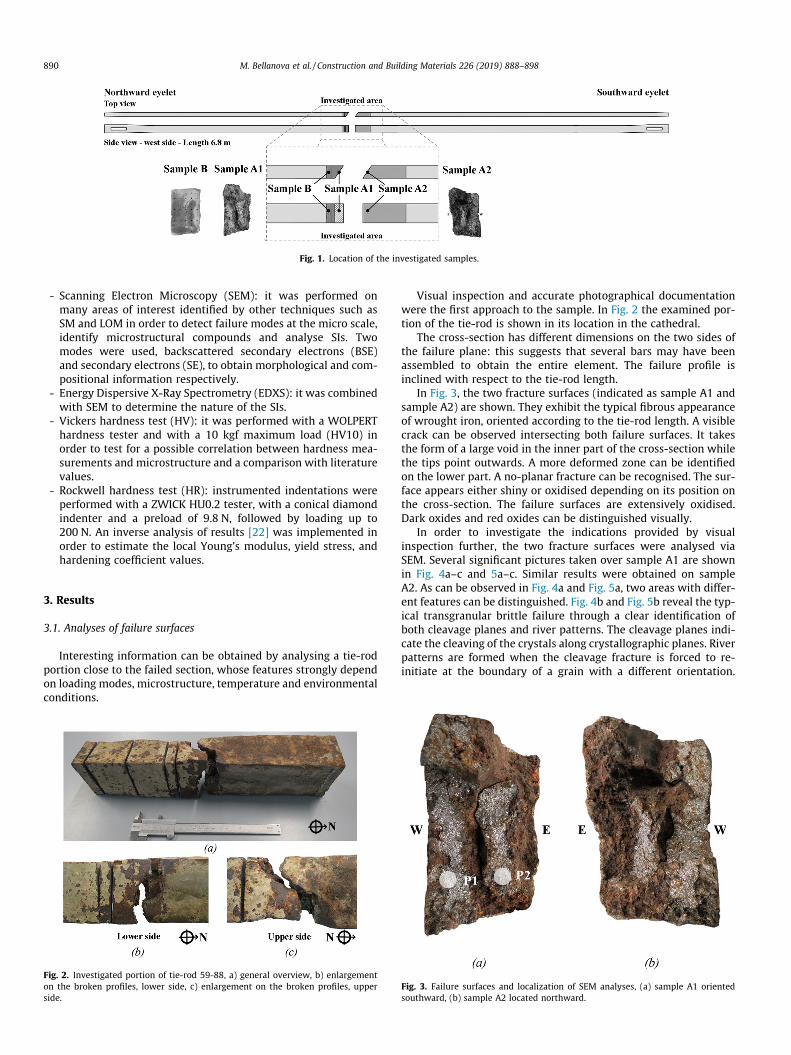
Fig. 1. Location of the investigated samples.
890 M. Bellanova et al. / Construction and Building Materials 226 (2019) 888–898
- Scanning Electron Microscopy (SEM): it was performed onmany areas of interest identified by other techniques such asSM and LOM in order to detect failure modes at the micro scale,identify microstructural compounds and analyse SIs. Twomodes were used, backscattered secondary electrons (BSE)and secondary electrons (SE), to obtain morphological and com-positional information respectively.
- Energy Dispersive X-Ray Spectrometry (EDXS): it was combinedwith SEM to determine the nature of the SIs.
- Vickers hardness test (HV): it was performed with a WOLPERThardness tester and with a 10 kgf maximum load (HV10) inorder to test for a possible correlation between hardness mea-surements and microstructure and a comparison with literaturevalues.
- Rockwell hardness test (HR): instrumented indentations wereperformed with a ZWICK HU0.2 tester, with a conical diamondindenter and a preload of 9.8 N, followed by loading up to200 N. An inverse analysis of results [22] was implemented inorder to estimate the local Young’s modulus, yield stress, andhardening coefficient values.
3. Results
3.1. Analyses of failure surfaces
Interesting information can be obtained by analysing a tie-rodportion close to the failed section, whose features strongly dependon loading modes, microstructure, temperature and environmentalconditions.
Fig. 2. Investigated portion of tie-rod 59-88, a) general overview, b) enlargementon the broken profiles, lower side, c) enlargement on the broken profiles, upperside.
Visual inspection and accurate photographical documentationwere the first approach to the sample. In Fig. 2 the examined por-tion of the tie-rod is shown in its location in the cathedral.
The cross-section has different dimensions on the two sides ofthe failure plane: this suggests that several bars may have beenassembled to obtain the entire element. The failure profile isinclined with respect to the tie-rod length.
In Fig. 3, the two fracture surfaces (indicated as sample A1 andsample A2) are shown. They exhibit the typical fibrous appearanceof wrought iron, oriented according to the tie-rod length. A visiblecrack can be observed intersecting both failure surfaces. It takesthe form of a large void in the inner part of the cross-section whilethe tips point outwards. A more deformed zone can be identifiedon the lower part. A no-planar fracture can be recognised. The sur-face appears either shiny or oxidised depending on its position onthe cross-section. The failure surfaces are extensively oxidised.Dark oxides and red oxides can be distinguished visually.
In order to investigate the indications provided by visualinspection further, the two fracture surfaces were analysed viaSEM. Several significant pictures taken over sample A1 are shownin Fig. 4a–c and 5a–c. Similar results were obtained on sampleA2. As can be observed in Fig. 4a and Fig. 5a, two areas with differ-ent features can be distinguished. Fig. 4b and Fig. 5b reveal the typ-ical transgranular brittle failure through a clear identification ofboth cleavage planes and river patterns. The cleavage planes indi-cate the cleaving of the crystals along crystallographic planes. Riverpatterns are formed when the cleavage fracture is forced to re-initiate at the boundary of a grain with a different orientation.
Fig. 3. Failure surfaces and localization of SEM analyses, (a) sample A1 orientedsouthward, (b) sample A2 located northward.

Fig. 4. SEM analyses on sample A1 at position P1. (a) general picture, enlargement on (b) transgranular brittle failure area, (c) ductile failure area.
Fig. 5. SEM analyses on sample A1 at position P2. (a) general picture, enlargement on (b) transgranular brittle failure area, (c) ductile failure area.
M. Bellanova et al. / Construction and Building Materials 226 (2019) 888–898 891
These tear ridges tend to merge in the direction of crack growth: adownward direction of propagation is suggested. In contrast,Fig. 4c and Fig. 5c clearly show dimples, which indicate a micro-void coalescence around discontinuities such as non-metallicinclusions and impurities. Dimples are symptomatic of a ductilefracture mode. Compositional analysis was performed by EDXSon the inclusion inside a dimple shown in Fig. 4c. As can be seenin Table 1, the main element detected (excluding Fe, C, and O) is Si.
3.2. Microstructural characterisation
Microstructural characterisation was carried out on a cross-section close to the fracture surface (sample B). It was prepared
Table 1EDXS compositional semiquantitative analysis on the inclusion inside a dimple.
Elements O Na Mg Al Si
Weight [%] 26.4 – 2.0 1.7 13.4
by planar grinding and polishing, according to the ASTM E3-11Standard Guide for Preparation of Metallographic Specimens [32].Preliminary inspections of the whole cross-section were performedusing the stereo microscope. Several interesting pictures areshown in Fig. 6a–e.
A visible crack crosses the whole specimen. Inside the crack,rust was detected (Fig. 6b and c), suggesting that the crack is notof recent formation. The material is highly defective and manykinds of discontinuities were distinguished, such as porosities,inclusions, macrovoids, and microcracks. Discontinuities of micro-metric dimensions or smaller are more concentrated mainly closeto the visible crack (Fig. 6a and b). Larger flaws are randomly dis-tributed, especially on the westward portion of the cross-section
P S K Ca Mn Fe
3.4 – – 4.8 7.3 Bal.

Fig. 6. Stereomicrographs on sample B (a) crack tip, (b) concentrated discontinuities close to the main crack, (c) crack bifurcation, (d) isolated discontinuities, (e) hammerslaglayer and voids (f) localization of pictures.
892 M. Bellanova et al. / Construction and Building Materials 226 (2019) 888–898
(Fig. 6d). A 0.2–0.3 mm-thick hammerslag layer (oxide producedduring hot working) covers the tie-rod (Fig. 6e). It is almost uni-form and coherent with the wrought iron core and has probablyhad a protective effect against corrosion. Very large voids arelocated below the crust at a depth of up to 15 mm.
After stereo analysis, metallographic etching was carried out onthe surface inspected by using nital 2% (solution of nitric acid inethyl alcohol) in order to reveal the microstructure according toASTM E407-07 (2015) Standard Practice For Microetching Metalsand Alloys [33].
As other studies, including [6], have suggested, some prelimi-nary qualitative insights can be obtained by observing the etchedsection, the superficial features of which depends on the carboncontent. Usually the areas with a carbon content of over 0.2–0.3%appear more opaque. This indication allows an initial distinctionto be made at the macro scale between regions characterised bydifferent carburisation states. As Fig. 7b shows, three different con-ditions can be distinguished:
- 35% of the surface has a C content lower than or equal to 0.2%;- 20% of the surface has a C content ranging from 0.4% to 0.2%;- 45% of the surface has a C content greater than or equal to 0.4%.
3.2.1. Metal matrixLOM analysis confirmed the macroscopic observations. Two
main microstructures were identified, namely ferrite and pearlite,and their percentage over the sample is not uniform. In order to
coordinate the results provided by different techniques, a grid of40 points, with a spacing of 10 mm, was traced (Fig. 8).
Micrographs at 100X were taken at each node. Fig. 9a–g showseveral of the microstructures identified. The fractions of themicrostructural compounds were determined according to ASTME 562-02 Standard Test Method for Determining Volume Fractionby Systematic Manual Point Count [34]. A highly heterogeneousdistribution of the two main microstructural compounds wasobserved: the percentage of pearlite ranges from 97% (Fig. 9c) to0% (Fig. 9f). The grid nodes were classified into three categoriesdepending on the percentage of pearlite (Table 2). The discrete datasystem was transformed into a continuous distribution by interpo-lating the nodal values and the results were plotted in the colouredcontour map shown in Fig. 9. An examination of the LOM micro-graphs reveals that ferrite nucleates at the grain boundary andgrows with lamellar shape. Especially in Fig. 9d, Widmanstättenplates can be observed. In addition to ferrite and pearlite, cemen-tite was occasionally detected (Fig. 9b and e).
The area close to the macroscopic crack was also analysed indetail. Fig. 10a and b are illustrative pictures taken by opticalmicroscope before and after etching, respectively. Concentratedinclusions and a sudden change of both microstructure and grainsize can be observed across the crack.
3.2.2. Analysis of slag inclusionsWith regard to SIs, before the industrial revolution, both
wrought iron and steel working were performed at temperatures

Fig. 7. Carbon content evaluation at the macroscopic level (a) real surface after etching, (b) categorization of the cross-section area.
Fig. 8. Reference grid.
M. Bellanova et al. / Construction and Building Materials 226 (2019) 888–898 893
below the melting point of iron and hence different types ofnon-metallic particles remained entrapped in the metallicmatrix. They were typically identified by stereoscopic analysisbut sometimes could not be easily distinguished from smallvoids. With the advent of LOM it became possible to identifySIs in the ferrite matrix with certainty and inspect their features.Two examples are shown in Fig. 11a and b. Both of them areiron-rich inclusions. Fig. 11a illustrates a bulky two-phase SI ofwüstite and glass, while Fig. 11b depicts a slender two-phaseSI of fayalite and glass.
In contrast, SIs in the pearlite matrix cannot be easily distin-guished from voids using LOM. Therefore, in order to characterisethem properly, SEM analysis coupled with EDXS was used. Afterobtaining a complete overview of the whole cross-section, four sig-nificant points were chosen to perform SEM analyses:
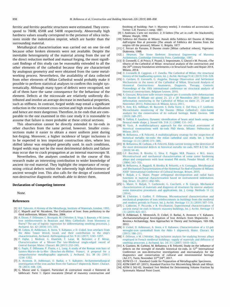
- close to the upper tip of the visible crack (pearlite 60% and fer-rite 40%, Fig. 12a);
- close to the widest part of the visible crack (pearlite 62% andferrite 38%, Fig. 12b);
- undamaged material (pearlite 0% and ferrite 100%, Fig. 12c).
- close to the lower tip of the visible crack (pearlite 20% and fer-rite 80%, Fig. 12d).
At the same position, BSE often revealed the presence of differ-ent types of SIs. Each one of them was studied by EDXS. The resultsare reported in Table 3.
The pictures in Fig. 12a and b were taken of material charac-terised by approximately the same percentage of ferrite and pear-lite. Different types of inclusions were revealed. In Fig. 12a, theparticularly high percentage of Si (about 63%) at the A-inclusionsuggests a glassy SI (iron content is negligible). In contrast, thechemical analysis of the B-inclusion in Fig. 12a and the C-inclusion in Fig. 12b suggests an iron-rich glassy composition. Asexpected, inclusions of rust were identified inside the crack (D-inclusion in Fig. 12a), as indicated by the detection of mostly Feand O.
In Fig. 12c, the metal matrix is pure ferrite (0% pearlite). Thedetected inclusion has a bulky shape and a pale dendritic phasewith a glassy appearance. EDXS analysis reveals a Fe-rich inclusionwith a significant amount of Si (13.10%). More specifically, it ischaracterised by dendrites of wüstite (FeO) in a glassy matrix.There is also a significant presence of Ca and Mn, the content ofwhich is 4.75% and 6.33%, respectively. Carbon is completelyabsent. The morphology is very similar to inclusions in Fig. 11, asdetected by LOM. Indeed, the same metal matrix surrounds it.
The picture in Fig. 12d shows the mostly ferritic microstructure(80% ferrite and 20% pearlite). EDXS on the F-inclusion revealediron oxides, as in the other inclusion analysed inside the crack.The G-inclusion is spheroidal graphitic carbon, the enlargementof which is shown in Fig. 12e. Its size is about 10–15 lm. This kindof inclusion is recurring in the mostly ferritic iron part of the sam-ple. Around nodules, a finer pearlite can be usually found, becom-ing progressively coarser. H-inclusion in Fig. 13d is iron-free, withhigh percentage of Si, Ca, and Mn.
3.2.3. Hardness testsVickers and Rockwell hardness tests were carried out on the
polished surface by conforming to the same grid used for the opti-cal microscope observation. The two measurements were recipro-cally shifted by 4 mm in order to avoid any interaction. Asexpected, in the mostly pearlitic structure the indenter produceslocal cracking around the indentation area, while in the mostly fer-ritic structure only local plastic deformation occurs. This confirms
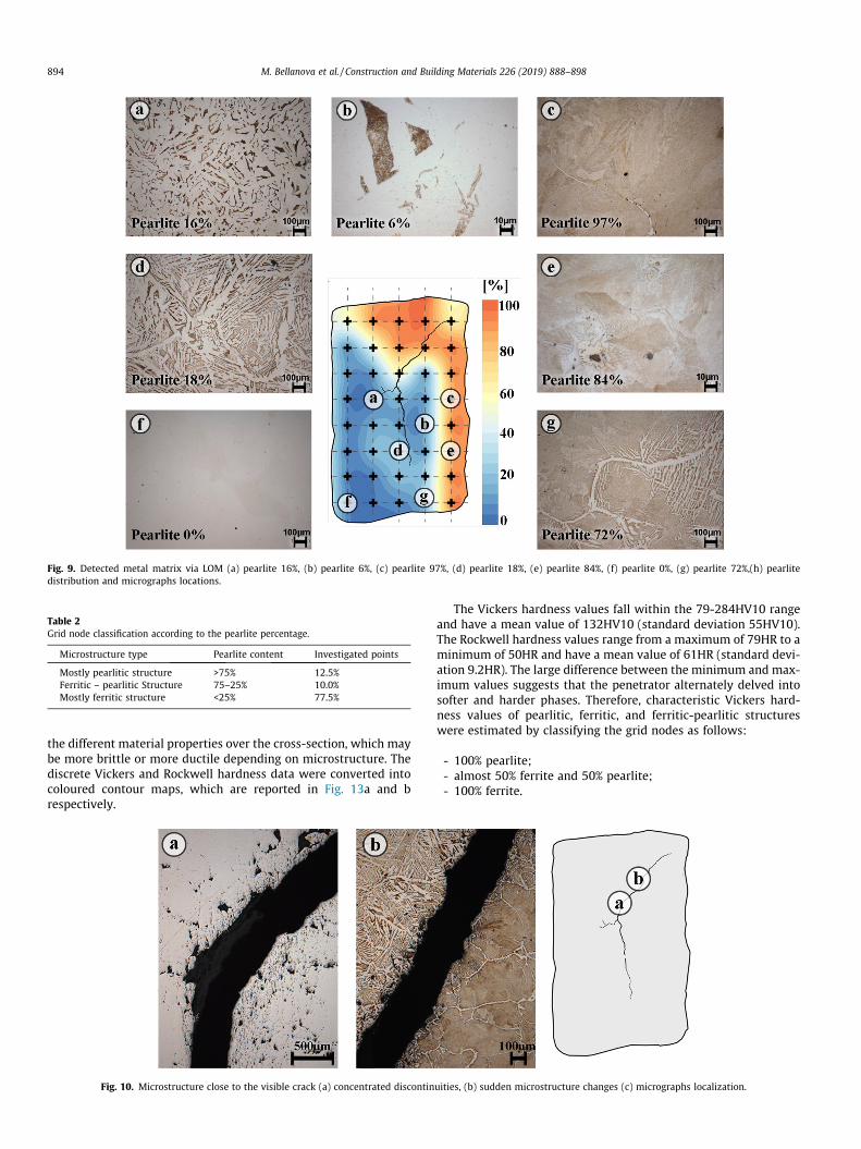
Fig. 9. Detected metal matrix via LOM (a) pearlite 16%, (b) pearlite 6%, (c) pearlite 97%, (d) pearlite 18%, (e) pearlite 84%, (f) pearlite 0%, (g) pearlite 72%,(h) pearlitedistribution and micrographs locations.
Table 2Grid node classification according to the pearlite percentage.
Microstructure type Pearlite content Investigated points
Mostly pearlitic structure >75% 12.5%Ferritic – pearlitic Structure 75–25% 10.0%Mostly ferritic structure <25% 77.5%
894 M. Bellanova et al. / Construction and Building Materials 226 (2019) 888–898
the different material properties over the cross-section, which maybe more brittle or more ductile depending on microstructure. Thediscrete Vickers and Rockwell hardness data were converted intocoloured contour maps, which are reported in Fig. 13a and brespectively.
Fig. 10. Microstructure close to the visible crack (a) concentrated discontin
The Vickers hardness values fall within the 79-284HV10 rangeand have a mean value of 132HV10 (standard deviation 55HV10).The Rockwell hardness values range from a maximum of 79HR to aminimum of 50HR and have a mean value of 61HR (standard devi-ation 9.2HR). The large difference between the minimum and max-imum values suggests that the penetrator alternately delved intosofter and harder phases. Therefore, characteristic Vickers hard-ness values of pearlitic, ferritic, and ferritic-pearlitic structureswere estimated by classifying the grid nodes as follows:
- 100% pearlite;- almost 50% ferrite and 50% pearlite;- 100% ferrite.
uities, (b) sudden microstructure changes (c) micrographs localization.

Fig. 11. LOM analyses on the two-phase inclusions detected in ferrite matrix. (a) wüstite and glass, (b) fayalite and glass, (c) micrographs localization.
M. Bellanova et al. / Construction and Building Materials 226 (2019) 888–898 895
Since the variability in these subintervals is low, the averagevalues can be assumed as the representative values for the metalmatrix considered. According to this procedure, ferrite could beassociated with 94HV10, pearlite-ferrite with 148HV10, and pear-lite with 223HV10.
A 3D micro geometrical survey was performed using the ALI-CONA Infinite Focus 3D optical microscope inside the indentationimprint of points exceeding the intervals defined by mean valueand standard deviation and iron-free glassy inclusions weredetected.
An inverse analysis was performed at each location where hard-ness was measured, exploiting the pertinent indentation curve asinput data in order to estimate the material parameters governingthe mechanical behaviour such as Young’s modulus, yield strengthand hardening coefficient. As discussed in [23] the estimation ofthese values is not convincing because the estimated Young’s mod-ulus fell within a reasonable range of 180–220 GPa only in fournodes. This could be explained by the strict assumptions underly-ing the method, namely isotropic and homogeneous material witha grains size at least two orders of magnitude smaller than thedimension of the indentation imprint and characterised by linearelasticity and exponential hardening law in the plastic stage [2425]. As a matter of fact, these conditions are not appropriate forthe examined material.
4. Discussion
The two failure surfaces provide interesting information aboutthe failure mechanism. Dark oxides are usually produced at theforging temperature and hence are a result of the manufacturingprocess; red oxides, commonly known as ‘‘rust”, form at room tem-perature. The latter are fairly evenly distributed over the wholecross-section and are caused by atmospheric corrosion. This evi-dence is in agreement with the results of microclimate monitoring[17], which revealed that for most of the year relative humidityexceeds the recommended limit of 50%, favouring the onset of cor-rosion in metallic materials. However, the characteristics of thefracture surfaces, as well as the generalised corrosion itself, indi-cate a failure that was mainly determined by mechanical proper-ties, defectiveness and load conditions. It is reasonable to assumethat the crack nucleated inside the section in a weaker region ofthe material of sizable dimensions (�5–8 mm), where local stressconcentration occurred. The position of the visible crack acrossthe specimen slices suggests an inclined propagation relative tothe tie-rod length. Non-homogeneous mechanical properties can
be inferred from the appearance of the failure surfaces. Thishypothesis is confirmed by SEM analyses revealing both brittleand ductile collapse mechanisms. The former is associated withthe shiny cross-section surface while the latter is associated withthe more opaque part. The remarkable heterogeneity of the mate-rial and the presence of silica oxides suggest iron smelting in a low-reducing, non-homogeneous atmosphere. As noted above, theseconditions may be associated with older furnaces, based on thedirect method of reduction.
The differences in the amount of carbon in the cross-sectionscan be accounted for by poor hot working resulting from hand-work. However, the level of carburisation is relatively high com-pared with values measured in the tie-rods of other churches ofthe same period [26]. This aspect can be attributed to the employ-ment of highly qualified blacksmiths due to the importance ofMilan Cathedral. The evaluation of carbon content evaluation atthe macroscopic level as displayed in Fig. 8b can be completelyoverlapped with the observations made at the microscopic scale.The most highly carburised part of the cross-section correspondsto the mostly pearlitic microstructure, which has a higher carboncontent than the ferritic matrix. More generally, the distributionof the main microstructural compounds, i.e. ferrite and pearlite,indicates a highly heterogeneous material, confirming the hypoth-esis regarding the furnace based on the analysis of the fracture sur-face. These items of evidence are confirmed in the literature bymany authors, including [27] [3] and [6]. However, the mostly fer-ritic metal matrix is prevalent and corresponds, as expected, to themost highly deformed portion of the cross-section (higher ductil-ity). Grain boundaries can be clearly identified only where thesame amount of ferrite and pearlite occurs. They have large sizes(hundreds of microns), but their dimensions are extremely hetero-geneous. Widmanstätten plates can be observed in these regions aswell. The formation of this particular microstructure is highlydependent on the chemical composition of the bloom and the cool-ing temperature. Specifically, it can be recognised in low carboncontent material and indicates a very high forging temperature(950 �C–1100 �C), followed by a rapid cooling process. It is typicalof wrought iron produced by the direct process [28].
The heterogeneity of the material is also related to its inherentdefectiveness. A stereoscopic examination provides a general over-view of the distribution of defects. However, at this inspectionscale it was not possible to distinguish their features. LOM andSEM enabled larger inclusions ( 200 mm) detected in the mostlyferritic microstructure to be characterised. As shown in Fig. 12,there are two different types of iron-rich two-phase inclusions.Both of them suggest the use of the direct method of reduction;
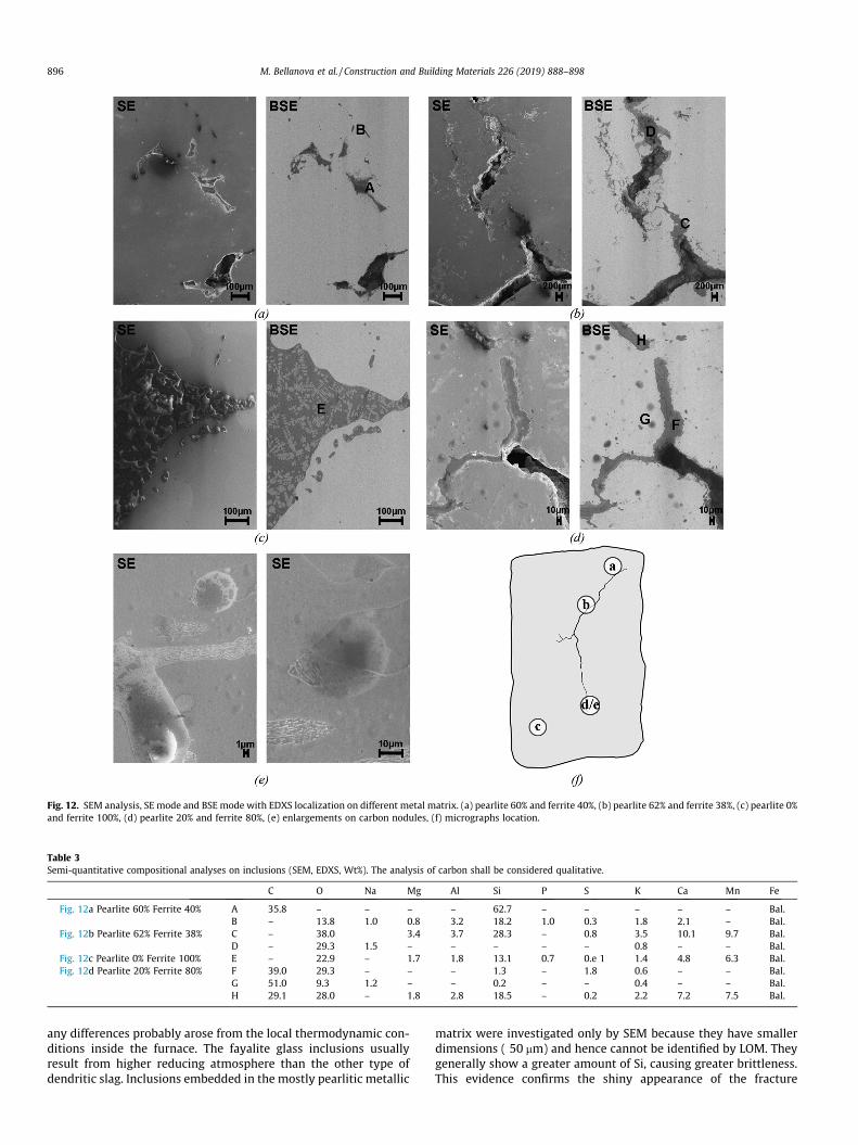
Table 3Semi-quantitative compositional analyses on inclusions (SEM, EDXS, Wt%). The analysis of carbon shall be considered qualitative.
C O Na Mg Al Si P S K Ca Mn Fe
Fig. 12a Pearlite 60% Ferrite 40% A 35.8 – – – – 62.7 – – – – – Bal.B – 13.8 1.0 0.8 3.2 18.2 1.0 0.3 1.8 2.1 – Bal.
Fig. 12b Pearlite 62% Ferrite 38% C – 38.0 3.4 3.7 28.3 – 0.8 3.5 10.1 9.7 Bal.D – 29.3 1.5 – – – – – 0.8 – – Bal.
Fig. 12c Pearlite 0% Ferrite 100% E – 22.9 – 1.7 1.8 13.1 0.7 0.e 1 1.4 4.8 6.3 Bal.Fig. 12d Pearlite 20% Ferrite 80% F 39.0 29.3 – – – 1.3 – 1.8 0.6 – – Bal.
G 51.0 9.3 1.2 – – 0.2 – – 0.4 – – Bal.H 29.1 28.0 – 1.8 2.8 18.5 – 0.2 2.2 7.2 7.5 Bal.
Fig. 12. SEM analysis, SE mode and BSE mode with EDXS localization on different metal matrix. (a) pearlite 60% and ferrite 40%, (b) pearlite 62% and ferrite 38%, (c) pearlite 0%and ferrite 100%, (d) pearlite 20% and ferrite 80%, (e) enlargements on carbon nodules, (f) micrographs location.
896 M. Bellanova et al. / Construction and Building Materials 226 (2019) 888–898
any differences probably arose from the local thermodynamic con-ditions inside the furnace. The fayalite glass inclusions usuallyresult from higher reducing atmosphere than the other type ofdendritic slag. Inclusions embedded in the mostly pearlitic metallic
matrix were investigated only by SEM because they have smallerdimensions ( 50 mm) and hence cannot be identified by LOM. Theygenerally show a greater amount of Si, causing greater brittleness.This evidence confirms the shiny appearance of the fracture

Fig. 13. Hardness values distribution, a) Vickers HV10, b) Rockwell HR.
M. Bellanova et al. / Construction and Building Materials 226 (2019) 888–898 897
surfaces. The main difference between the A-inclusion in Fig. 13aand the D-inclusion in Fig. 13b is the relatively high content ofCa (10.14%) and Mn (9.66%) in the latter, which usually originatesfrom ashes and ore, respectively. Carbon-rich inclusions and rustwere identified as well. As the percentage of ferrite increases, theamount of Si decreases and iron-rich inclusions are more frequent.This correlation between metal matrix and type of slag is con-firmed in the literature, as shown in [29] and [30].
The microstructural findings in terms of matrix and types ofinclusions show a strong agreement with the hardness testingresults. The distribution of Vickers and Rockwell hardness valuescan be completely overlapped with the pearlite content map:higher hardness values correspond to the mostly pearliticmicrostructure with mainly silica-rich inclusion while the lowestones correspond to the mostly ferritic microstructure with iron-rich inclusions. With regard to hardness values, the comparisonwith similar case studies is not meaningful because small differ-ences in the metal matrix as well as in grain dimensions maystrongly influence the results.
All of the evidence from analyses at different inspection scalesleads to the hypothesis of the direct reduction method. Neverthe-less, slag inclusions recognised in other similar cases [27] areusually much larger than those identified in the Milan Cathedraltie-rod. It is reasonable to assume the use of a more accuratemetalworking process due to the relevance of the building. Indeed,the fracture characterisation that was performed [31] reveals anextremely tough base material. A hardening branch without localinstabilities dominates the load-displacement curve, plastic defor-mations are extremely marked and the ultimate strength is neverreached in the strain range allowed by the test. The same studydemonstrates that the mechanical performance of the materialdecreases sharply at forged welds due to the heat treatment used.In samples including forged welds, the load-displacement curveshows a softening branch and an unstable crack propagation asso-ciated with the presence of local discontinuities. The resultingtoughness values are about one order of magnitude lower thanthe base material. For this reason, forged welds can be consideredthe most critical cross-sections. This evidence cannot be directlyextended to all historical tie-rods, as it depends on the averagedimensions of slag inclusions.
The tie-rod failure analyses of the replaced element confirm thisinsight. The crack propagated along an inclined direction withrespect to the longitudinal tie-rod axis, recalling the typical forgedweld shape. Moreover, the crack visible over the cross-section islocated across a region where concentrated discontinuities andsudden change of microstructure occurred, as shown via LOMbefore and after etching. As mentioned previously, in the literature
these two occurrences are often associated with the presence offorged welding of two wrought-iron pieces [6]. This evidence, com-bined with the results of visual inspection, leads to the hypothesisof crack propagation along a forged weld, which is in agreementwith the lower toughness observed at these locations.
5. Conclusions
The behaviour of wrought iron tie-rods in historical buildings isstrongly affected by heterogeneity and defectiveness in the mate-rial stemming from the manufacturing techniques used. In thispaper, the case study of the Milan cathedral tie-rods wasaddressed. Many analyses were conducted at different inspectionscales in order to infer possible causes of tie-rod failure in connec-tion with metallurgical features of the material.
Many observations led to the hypothesis that tie-rod failed dueto a crack initiating inside the cross-section at a weaker point(macroscopic inclusion or void) and propagating outward along aforged weld. Crack morphology on the examined cross-sectionand along the tie-rod length indicates the direction of propagation.Concentrated inclusions and sudden variations of microstructureacross the crack highlighted via LOM suggest the presence of aforged weld. Lower toughness values at this region achieved bythe mechanical characterisation described in [31] confirm thismentioned insight. Moreover, the macroscopic crack detected inanother tie-rod substituted in 2014 exhibits the same straight-scarf forged weld shape. This evidence endorses the results of thepresent study.
Failure mode is not homogeneous and both transgranular brit-tle and ductile failures were identified over the fracture surfaces.Brittle and ductile failure modes were identified very close toone another. Ductile failure corresponds to the most highlydeformed part identified through the visual inspection.
These insights are in agreement with the microstructural find-ings. The material is extremely heterogeneous in terms of bothmicrostructural compounds and defects. Although ferrite and pear-lite are the prevalent microstructures, their distribution over thecross-section is extremely variable. Two distinct more homoge-nous areas can be identified, corroborating the hypothesis of differ-ent mechanical properties over the investigated cross-section.Across their boundary, microstructure and grain size suddenlychange, two pieces of evidence which substantiate the hypothesisof a forged weld between two bars at this location. More generally,the mostly ferritic structure is prevalent and characterises 78% ofthe examined grid nodes. As the percentage of pearlite contentincreases, the amount of carbon increases, and hence also strengthand brittleness. With regard to defects, different types of flawsresulting from the manufacturing process were identified, suchas microcracks, micro-porosities, voids and slag inclusions. Astrong correlation was found between the identified microstruc-tures (ferrite, pearlite) and the type of discontinuities. Iron-richdendritic slag inclusions (typically wüstite) characterise the ferriticmatrix. Spheroidal graphitic carbon was identified in regionswhere the ferritic structure is prevalent. Fine pearlite nucleatesaround carbon nodules. These two types of inclusions are com-pletely absent from the mostly pearlitic structure, where smallerglassy slags were detected. Microcracks were identified as well.Usually inside cracks iron oxide inclusions were recognised.
Both microstructural compounds and defects strongly affectmechanical properties. Indeed, metallurgical characterisationshows a strong agreement with the results of hardness tests. Datavariability confirms the heterogeneity of the material. Higher hard-ness values were found in the primarily pearlitic microstructure,while the lowest values were observed mostly in the ferriticmicrostructure. Distinctive hardness values related to pearlitic,
898 M. Bellanova et al. / Construction and Building Materials 226 (2019) 888–898
ferritic and ferritic-pearlitic structures were estimated. They corre-spond to 76HR, 65HR and 54HR respectively. Abnormally highhardness values usually correspond to the presence of silica inclu-sions inside the indentation imprint, which are harder than thesurrounding material.
Metallurgical characterisation was carried out on one tie-rodbecause other broken elements were not available. Despite theinevitable heterogeneity of the material arising from the use ofthe direct reduction method and manual forging, the most signifi-cant findings of this study can be reasonably extended to all theother elements of the cathedral because they are characterisedby analogous geometry and were obtained from the same metal-working process. Nevertheless, the availability of data collectedfrom other elements of Milan Cathedral would probably make itpossible to perform statistical analyses to confirm this insight sys-tematically. Although many types of defects were recognised, notall of them have the same consequence for the behaviour of theelement. Defects at the microscale are relatively uniformly dis-tributed and involve an average decrease in mechanical properties,such as stiffness. In contrast, forged welds may entail a significantreduction in the resistant cross-section and high strain localisationand hence are more dangerous. Therefore, in tie-rods that are com-parable to the one examined in this case study it is reasonable toassume that failure is more probable at these critical sections.
This observation cannot be directly extended to tie-rods inother churches from the same period, however. Smaller cross-sections make it easier to obtain a more uniform joint duringhot-forging. Moreover, a higher incidence of larger inclusions isto be expected in less important construction sites, where lessskilled labour was employed generally used. In such conditions,forged welds may not be the most detrimental defects and failuremay occur due to crack propagation at an internal macroscopic SI.
Nevertheless, the analyses conducted in the course of thisresearch make an interesting contribution to wider knowledge ofancient tie-rod material. They highlight the importance of recog-nising critical defects within the inherently high defectiveness ofancient wrought iron. This also calls for the design of customisednon-destructive diagnostic methods able to detect them.
Declaration of Competing Interest
None.
References
[1] R.F. Tylecote, A History of the Metallurgy, Institute of Materials, London, 1992.[2] C. Mapelli and W. Nicodemi, The Civilisation of Iron: from prehistory to the
third millenium, Milano: Olivares, 2004.[3] A. Disser, P. Dillmann, C. Bourgain, M. L’Héritier, E. Vega, S. Bauvais, e M. Leroy,
Iron reinforcements in Beauvais and Metz Cathedrals: from bloomery orfinery? The use of logistic regression for differentiating smelting processes, J.Archaeol. Sci. 42 (2014) 315–333.
[4] M. Cohen, D. Ashkenazi, A. Stern, Y. Kahanov, e D. Cvikel, Iron artefacts fromthe Akko Tower Wreck, Israel, and their contribution to the ship’scharacterization, Archaeol. Anthropological Sci. 9 (6) (2017) 1243–1257.
[5] P. Fajfar, J. Medved, G. Klancnik, T. Lazar, M. Necemer, e P. Mrvar,Characterization of a Messer–The late-Medieval single-edged sword ofCentral Europe, Mater. Charact. 86 (2013) 232–241.
[6] G. Pagès, P. Dillmann, P. Fluzin, e L. Long, A study of the Roman iron bars ofSaintes-Maries-de-la-Mer (Bouches-du-Rhône, France). A proposal for acomprehensive metallographic approach, J. Archaeol. Sci. 38 (6) (2011)1234–1252.
[7] A. Aronson, D. Ashkenazi, O. Barkai, e Y. Kahanov, Archaeometallurgicalinvestigation of the iron anchor from the Tantura F shipwreck, Mater. Charact.78 (2013) 108–120.
[8] G. Musso and G. Copperi, Particolari di costruzioni murali e finimenti difabbricati: Parte 1: Opere muratorie [Detail of masonry construction and
finishing of building: Part 1: Masonry works], 3 riveduta ed accresciuta ed.,Torino: G.B. Paravia e comp. 1887.
[9] I. Andreani, L’arte nei mestieri. 2: Il fabbro [The art in craft: the blacksmith],Milano: Hoepli, 1998.
[10] Fabbrica del Duomo di Milano, Annali della Fabbrica del Duomo di Milanodall’origine fino al presente [The annals of Fabbrica del Duomo from theorigins till the present], Milano: G. Brigola, 1877
[11] C. Ferrari da Passano, Il Duomo rinato [Milan cathedral reborn], Vigevano:Diakronia, 1988.
[12] J. Heyman, The Stone Skeleton: Structural Engineering of MasonryArchitecture, Cambridge University Press, Cambridge, 1997.
[13] D. Coronelli, C. di Prisco, F. Pisanò, S. Imposimato, S. Ghezzi e M. Pesconi, «Thetiburio of the Cathedral of Milan: structural analysis of the construction andthe 20th century foundation settlements,» in Structural Faults and Repair 2014,Milano, 2014.
[14] D. Coronelli, B. Caggioni, e F. Zanella, The Cathedral of Milan: the structuralhistory of the loadbearing system, Int. J. Archit. Heritage 9 (4) (2015) 510–528.
[15] G. Cardani, D. Coronelli, G. Angjeliu, Damage Observation and SettlementMechanisms in the naves of the Cathedral of Milan, Structural Analysis ofHistorical Constructions: Anamnesis, Diagnosis, Therapy, Controls,Proceedings of the 10th international conference on structural analysis ofhistorical constructions, Belgium Leuven, 2016.
[16] A. Giussani, Relazione sulle misure eseguite per il controllo delle deformazionidel Duomo di Milano nei giorni 21, 23 e 28 Novembre 2011 [Report ondeformation monitoring in the Cathedral of Milan on dates 21, 23 and 28November 2011], Politecnico di Milano, Lecco, 2011.
[17] N. Aste, R.S. Adhikari, M. Buzzetti, S. Della Torre, C. Del Pero, e F. Lonforte,Microclimatic monitoring of the Duomo (Milan Cathedral): risks-basedanalysis for the conservation of its cultural heritage, Build. Environ. 148(2019) 240–257.
[18] N. Tullini, F. Laudiero, Dynamic identification of beam axial loads using oneflexural mode shape, J. Sound Vib. 318 (1) (2008) 131–147.
[19] M. Vasic, A multidisciplinary approach for the structural assessment ofhistorical constructions with tie-rods PhD thesis, Milano: Politecnico diMilano, 2015.
[20] M. Bellanova, e R. Felicetti, A multidisciplinary strategy for the inspection ofhistorical metallic tie-rods: the milan cathedral case study, Int. J. Archit.Heritage 13 (3) (2019) 371–389.
[21] M. Bellanova, M. Carboni, e R. Felicetti, Eddy current testing to the detection ofthe most detrimental defects in historical metallic tie-rods, NDT & E Int. 104(2019) 34–41.
[22] G.F. Bocchini, B. Rivolta, G. Silva, E. Poggio, M.R. Pinasco, e M.G. Ienco,Microstructural and mechanical characterisation of some sinter hardeningalloys and comparisons with heat treated PM steels, Powder Metall. 47 (4)(2004) 343–351.
[23] M. Bellanova, A. Baggioli, B. Rivolta, R. Felicetti, e A. Cornaggia, Metallurgicaland Mechanical Characterization of the Historical Tie-Rod of Duomo di Milano,XXXI� International Conference of Cultural heritage, Brixen, 2015.
[24] V. Buljak, e G. Maier, Proper orthogonal decomposition and radial basisfunctions in material characterization based on instrumented indentation,Eng. Struct. 33 (2011) 492–501.
[25] G. Maier, V. Buljak, T. Garbowski, G. Cocchetti, e N. Giorgio, Mechanicalcharacterization of materials and diagnosis of structures by inverse analysis:some innovative procedures and applications, Int. J. Comp. Methods 11 (3)(2014).
[26] M. L’héritier, I. Guillot, P. Dillmann, Microstructural characterization andmechanical properties of iron reinforcements in buildings from the medievaland modern periods in France, Int. J. Archit. Heritage 13 (3) (2019) 507–519.
[27] C. Calderini, P. Piccardo, e R. Vecchiattini, Experimental characterization ofancient metal tie-rods in historic masonry buildings, Int. J. Archit. Heritage 13(3) (2019) 425–437.
[28] D. Ashkenazi, E. Mentovich, D. Cvikel, O. Barkai, A. Aronson e Y. Kahanov,«Archaeometallurgical Investigation of Iron Artifacts from Shipwrecks – AReview,» Archaeology, New Approaches in Theory and Techniques, 169-186,2012.
[29] D. Cvikel, D. Ashkenazi, A. Stern, e Y. Kahanov, Characterization of a 12-pdrwrought-iron cannonball from the Akko 1 shipwreck, Mater. Charact. 83(2013) 198–211.
[30] P. Dillman, e M. L’Héritier, Slag inclusion analysis for studying ferrous alloysemployed in French medieval buildings: supply of materials and diffusion ofsmelting processes, J. Archaeol. Sci. 34 (11) (2007) 1810–1823.
[31] A. Gianneo, M. Carboni, M. Bellanova, e R. Felicetti, Study on the influence ofdefects on the strenght of metallic historical tie-rods, in 12th InternationalConference on non-destructive investigations and microanalysis for thediagnostics and conservation of cultural and environmental heritage(Art.17), Turin, November 22nd/24th, 2017.
[32] ASTM E3-11 , Standard Guide for Preparation of Metallographic Specimens.[33] ASTM E407-07 (2015), Standard Practice For Microetching Metals and Alloys.[34] ASTM E 562-02, Standard Test Method for Determining Volume Fraction by
Systematic Manual Point Count.