metal shop - foundry_handbook
TRANSCRIPT

7/21/2019 Metal Shop - Foundry_handbook
http://slidepdf.com/reader/full/metal-shop-foundryhandbook 1/56
WHITING
useful
informationfor
foundrymen
METALLURGICALEQUIPMENT
SYSTEMS

7/21/2019 Metal Shop - Foundry_handbook
http://slidepdf.com/reader/full/metal-shop-foundryhandbook 2/56
A complete lineof
Ferrous Melting Equipment
With Materialand
Hot Metal Handling EquipmentEngineered for the job.
Copyright 2004, by Whiting Equipment Canada Inc., Welland, Ontario, L3B 5P4

7/21/2019 Metal Shop - Foundry_handbook
http://slidepdf.com/reader/full/metal-shop-foundryhandbook 3/56
The information herein is revised periodically to include themost current practical data useful to the people in the
Metallurgical Industry. Data is included on Induction Furnaces
to complete the line of melting and metal handling equipmentcovered herein. We hope you find this useful.
For more information or additional copies of this booklet,
please contact us.
Metallurgical Equipment Division
WHITING EQUIPMENT CANADA INC. Welland, Ontario, Canada
+1 905-732-7585
To Our F r iends
in the Metal Casting
Industry:
7/21/2019 Metal Shop - Foundry_handbook
http://slidepdf.com/reader/full/metal-shop-foundryhandbook 4/56
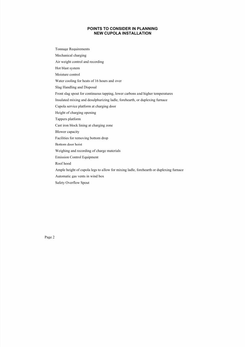
POINTS TO CONSIDER IN PLANNINGNEW CUPOLA INSTALLATION
Tonnage Requirements
Mechanical charging
Air weight control and recording
Hot blast system
Moisture control
Water cooling for heats of 16 hours and over
Slag Handling and Disposal
Front slag spout for continuous tapping, lower carbons and higher temperatures
Insulated mixing and desulphurizing ladle, forehearth, or duplexing furnace
Cupola service platform at charging door
Height of charging opening
Tappers platform
Cast iron block lining at charging zone
Blower capacity
Facilities for removing bottom drop
Bottom door hoist
Weighing and recording of charge materials
Emission Control Equipment
Roof hood
Ample height of cupola legs to allow for mixing ladle, forehearth or duplexing furnace
Automatic gas vents in wind box
Safety Overflow Spout
Page 2
7/21/2019 Metal Shop - Foundry_handbook
http://slidepdf.com/reader/full/metal-shop-foundryhandbook 5/56
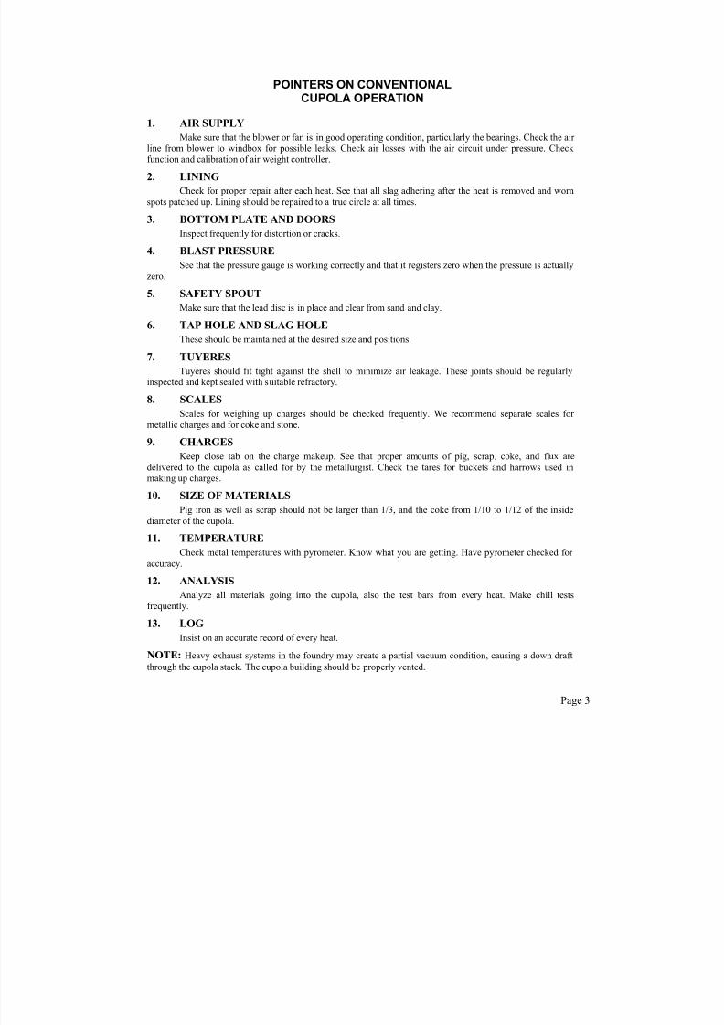
POINTERS ON CONVENTIONALCUPOLA OPERATION
1. AIR SUPPLY
Make sure that the blower or fan is in good operating condition, particularly the bearings. Check the air line from blower to windbox for possible leaks. Check air losses with the air circuit under pressure. Check
function and calibration of air weight controller.
2. LINING
Check for proper repair after each heat. See that all slag adhering after the heat is removed and worn
spots patched up. Lining should be repaired to a true circle at all times.
3. BOTTOM PLATE AND DOORS
Inspect frequently for distortion or cracks.
4. BLAST PRESSURE
See that the pressure gauge is working correctly and that it registers zero when the pressure is actually
zero.
5. SAFETY SPOUT
Make sure that the lead disc is in place and clear from sand and clay.
6. TAP HOLE AND SLAG HOLE
These should be maintained at the desired size and positions.
7. TUYERES
Tuyeres should fit tight against the shell to minimize air leakage. These joints should be regularlyinspected and kept sealed with suitable refractory.
8. SCALES
Scales for weighing up charges should be checked frequently. We recommend separate scales for metallic charges and for coke and stone.
9. CHARGES
Keep close tab on the charge makeup. See that proper amounts of pig, scrap, coke, and flux are
delivered to the cupola as called for by the metallurgist. Check the tares for buckets and harrows used inmaking up charges.
10. SIZE OF MATERIALS
Pig iron as well as scrap should not be larger than 1/3, and the coke from 1/10 to 1/12 of the inside
diameter of the cupola.
11. TEMPERATURE
Check metal temperatures with pyrometer. Know what you are getting. Have pyrometer checked for accuracy.
12. ANALYSIS
Analyze all materials going into the cupola, also the test bars from every heat. Make chill tests
frequently.
13. LOG
Insist on an accurate record of every heat.
NOTE: Heavy exhaust systems in the foundry may create a partial vacuum condition, causing a down draft
through the cupola stack. The cupola building should be properly vented.
Page 3

7/21/2019 Metal Shop - Foundry_handbook
http://slidepdf.com/reader/full/metal-shop-foundryhandbook 6/56
APPOXIMATE MELTING RATES IN TONS PER HOUR FORWHITING LINED CUPOLAS (Uninterrupted Operation)
METAL TO COKE RATIO (CRecommendedBlower Cap'y.
6:1 7:1 8:1 9
333#/ton 286#/ton 250#/ton 222
CupolaSize
ShellDiam.
LowerLiningThick-ness**
Diam.InsideLining
AreaInsideLining
Sq.In.
Theoretical Air Flow
thruTuyeresSCFM
VolumeICFM
Pressureoz./in.
2* 99ft
3/#c 107ft
3/#c 112ft
3/#c 118
0 27" 4½" 18" 254 573 640 8 1.1 1.3 1.4 -
1 32" 4½" 23" 415 937 1040 16 1.9 2.0 2.2 2
2 36" 4½" 27" 573 1293 1430 20 2.6 2.8 3.1 3
2½ 41" 7" 27" 573 1293 1430 20 2.6 2.8 3.1 3
3 46" 7" 32" 804 1815 2000 24 3.7 4.0 4.3 4
3½ 51" 7" 37" 1075 2426 2700 24 4.9 5.3 5.8 6
4 56" 7" 42" 1385 3126 3450 24 6.3 6.8 7.4 7
5 63" 9" 45" 1590 3589 4000 28 7.3 7.8 8.5 9
6 66" 9" 48" 1810 4085 4500 32 8.3 8.9 9.7 1
7 72" 9" 54" 2290 5170 5750 32 10.4 11.3 12.3 1
8 78" 9" 60" 2827 6380 7100 32 12.9 13.9 15.2 1
9 84" 9" 66" 3421 7720 8600 36 15.6 16.8 18.4 1
9½ 90" 9" 72" 4072 9190 10200 36 18.6 20.0 21.9 2
10 96" 9" 78" 4778 10790 11900 36 21.8 23.5 25.7 2
11 102" 12" 78" 4778 10790 11900 36 21.8 23.5 25.7 2
12 108" 12" 84" 5542 12510 13900 36 25.3 27.3 29.8 3
* Additional pressure capacity may be required when auxiliary equipment is added to the blast system or when ** For long heats use heavier lining or use water cooling.
Page 4
7/21/2019 Metal Shop - Foundry_handbook
http://slidepdf.com/reader/full/metal-shop-foundryhandbook 7/56
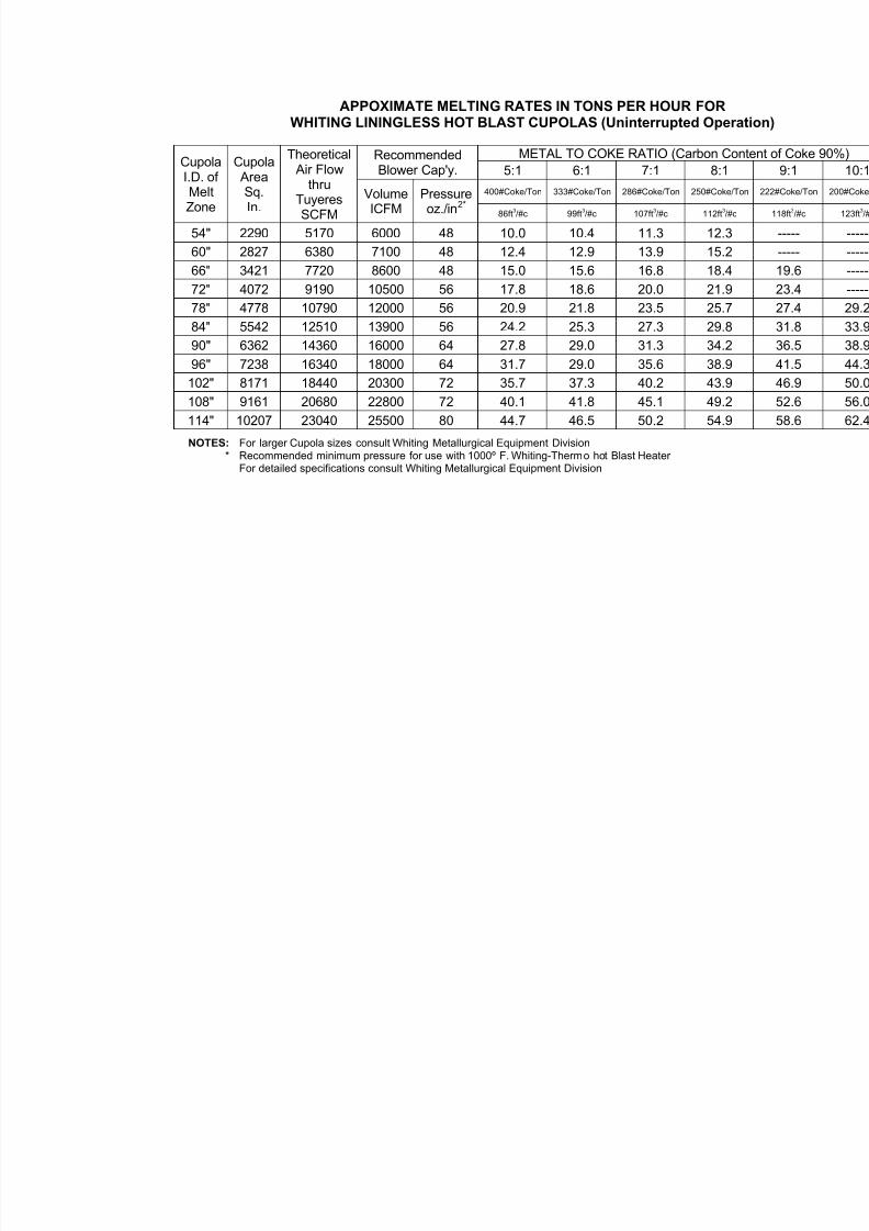
APPOXIMATE MELTING RATES IN TONS PER HOUR FORWHITING LININGLESS HOT BLAST CUPOLAS (Uninterrupted Ope
METAL TO COKE RATIO (Carbon CRecommended
Blower Cap'y. 5:1 6:1 7:1 8:1
400#Coke/Ton 333#Coke/Ton 286#Coke/Ton 250#Cok
CupolaI.D. ofMeltZone
Cupola AreaSq.In.
Theoretical
Air Flowthru
TuyeresSCFM
VolumeICFM
Pressureoz./in2*
86ft3/#c 99ft
3/#c 107ft
3/#c 112ft
3/
54" 2290 5170 6000 48 10.0 10.4 11.3 12.3
60" 2827 6380 7100 48 12.4 12.9 13.9 15.2
66" 3421 7720 8600 48 15.0 15.6 16.8 18.4
72" 4072 9190 10500 56 17.8 18.6 20.0 21.9
78" 4778 10790 12000 56 20.9 21.8 23.5 25.
84" 5542 12510 13900 56 24.2 25.3 27.3 29.890" 6362 14360 16000 64 27.8 29.0 31.3 34.2
96" 7238 16340 18000 64 31.7 29.0 35.6 38.9
102" 8171 18440 20300 72 35.7 37.3 40.2 43.9
108" 9161 20680 22800 72 40.1 41.8 45.1 49.2
114" 10207 23040 25500 80 44.7 46.5 50.2 54.9
NOTES: For larger Cupola sizes consult Whiting Metallurgical Equipment Division* Recommended minimum pressure for use with 1000º F. Whiting-Thermo hot Blast Heater
For detailed specifications consult Whiting Metallurgical Equipment Division
7/21/2019 Metal Shop - Foundry_handbook
http://slidepdf.com/reader/full/metal-shop-foundryhandbook 8/56
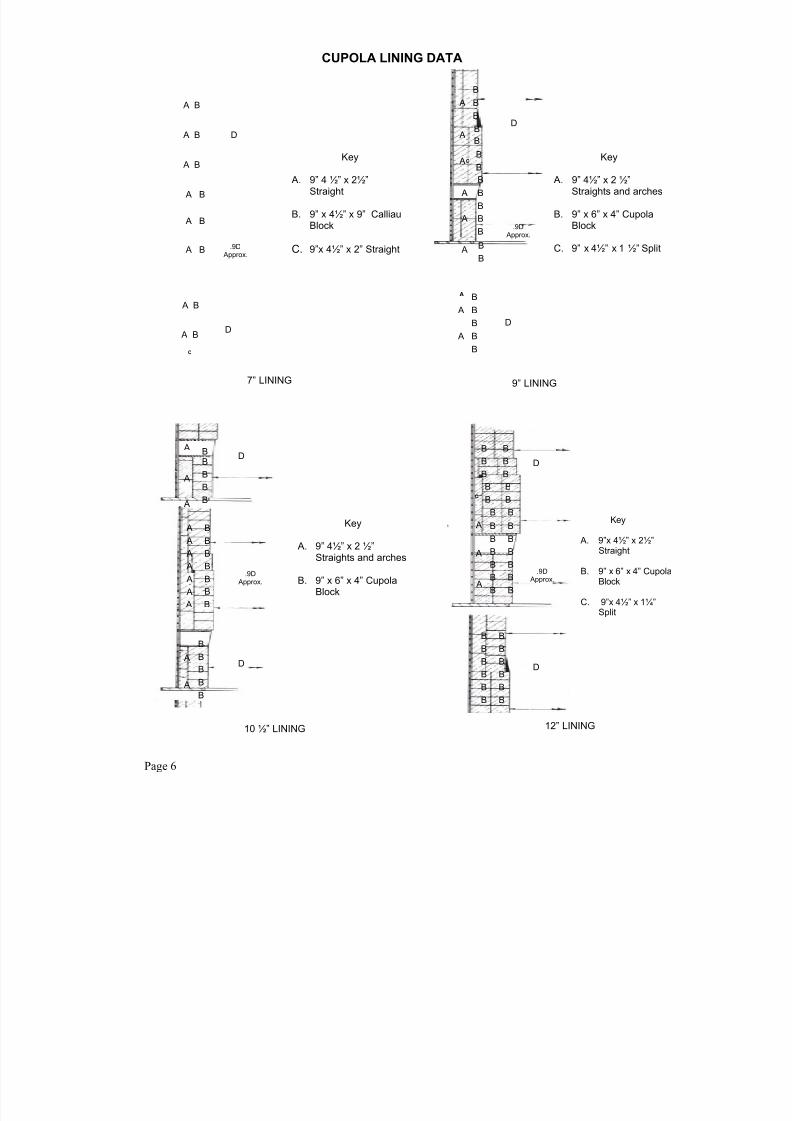
D
A B
D
Key
A. 9” 4 ½” x 2½”Straight
B. 9” x 4½” x 9” CalliauBlock
C. 9”x 4½” x 2” Straight
7” LINING
.9D Approx.
A B
A B
A B
A B
A B
A B
A B
Key
A. 9” 4½” x 2 ½”Straights and arches
B. 9” x 6” x 4” Cupola
Block
C. 9” x 4½” x 1 ½” Split
9” LINING
.9D Approx.
B
A B
B
B
A B
B
AB
B
AB
BC
A B
B
B
B A
C
A
A B
B
B
A B
B D
D
BB
B
B
B
B
B
B
B
B
B
B
B
B
B
B
B
A
A
A
A
A
A
A
A
A
A
A
A
D
D
Key
A. 9” 4½” x 2 ½”Straights and arches
B. 9” x 6” x 4” CupolaBlock
10 ½” LINING
.9D Approx.
B
B
B
B
B
B
B
B
B
B
B
B
B
B
B B
B
B
B
B
B
B
B
B
B
B
B
B
B
B
B
B
B B
B
B
A
A
A
C
Key
A. 9”x 4½” x 2½”Straight
B. 9” x 6” x 4” CupoBlock
C. 9”x 4½” x 1¼”Split
D
12” LINING
.9D Approx.
D
CUPOLA LINING DATA
Page 6

7/21/2019 Metal Shop - Foundry_handbook
http://slidepdf.com/reader/full/metal-shop-foundryhandbook 9/56
CUPOLA LININGSNUMBER OF BRICK AND BLOCK REQUIRED FOR WHITING CUP
NOTE: For long runs, heavier lining may be required. Consult your supplier for other
LOWER LINING U
Mat’ls Req’d per Foot of Height MatCupola
No.
ShellInside
Diam.
Inches
Lining
Thick-ness
Inches
CupolaInside
Diam.
Approx.Inches
Cupola
Block
Size No.
Cupola
Block
Pcs.
9” Str.
Brick
Pcs.
Fire
Clay
Lbs.
TotalWeight
Approx.
Lbs.
Lining
Thick-ness
Inches
9” S
Bric
Pcs
0
12
27”
32”36”
4½”
4½”4½”
18”
23”27”
* “A” 16-25
* “B” 21-30* “C” 27-36
12
1618
3
3
15
2224
335
442494
2½”2½”
2630
2½3
3½
41”46”
51”
7”7”
7”
27”32”
27”
* “C” 27-36* “D” 30-39
* “D” 30-39
* “E” 40-49
1820
6
16
3442
43
4044
47
740863
924
2½”2½”
2½”
3439
43
4
5
6
56”
63”
66”
7”
9”
9”
42”
45”
48”
* “E” 40-49
* * 42-54* * 48-60
* * 48-60
25
2733
63
51
55
56
54
72
76
1067
1390
1447
2½”
4½”
4½”
48
5
11
7
8
9
72”
78”
84”
9”
9”
9”
54”
60”
66”
* * 54-66
* * 60-72
* * 66-78
69
78
84
64
68
74
83
91
98
1681
1778
1920
4½”
4½”
4½”
20
32
42
9½
1011
12
90”
96”102”
108”
9”
9”12”
12”
72”
78”78”
84”
* * 72-84
* * 78-90* * 78-90
* * 90-102
* * 84-96* * 96-108
90
9696
108
102114
80
84
105
115122
130
2063
21943182
3370
4½”
4½”4½”
4½”
52
6572
82

7/21/2019 Metal Shop - Foundry_handbook
http://slidepdf.com/reader/full/metal-shop-foundryhandbook 10/56
CUPOLA LININGS
ALTERNATE ARRANGEMENTS FOR LOWER LINING, Cupola No. 0 ThUsing Standard arch and Straight Brick (2½” brick)
Materials Required Per Fo
Cupola
No.
ShellInside
Diam.
Inches
LiningThickness
Inches
Cupola
InsideDiam.
(Approx.)
Inches
No. 3Arch
Brick
Pcs.
No. 2Arch
Brick
Pcs.
No. 1Arch
Brick
Pcs.
9” Str.
BrickPcs.
0
12
2½
33½
4
27”
32”36”
41”
46”51”
56”
4½”
4½”4½”
7”
7”7”
7”
18”
23”27”
27”
32”37”
42”
6 40
4842
42
3224
15
720
20
3854
71
34
3943
48
USING STANDARD CIRCLE BRICK (9” x 4½” x 2½”) Cupola No. 1 ThrMaterials Required Per Foo
Cupola
No.
ShellInside
Diam.
Inches
Lining
ThicknessInches
Cupola
Inside
Diam.(Approx.)
Inches
24-33Circle
Brick
Pcs.
36-45Circle
Brick
Pcs.
45-57Circle
Brick
Pcs.
9” Str.
BrickPcs.
12
2½
33½4
32”36”
41”
46”51”56”
4½”4½”
7”
7”7”7”
23”27”
27”
32”37”42”
5844
44
20
20
20
536839
1048
34
394348
Note:– 3” series brick in these shapes are available – fewer bricks with fewer joints wou
Page 8

7/21/2019 Metal Shop - Foundry_handbook
http://slidepdf.com/reader/full/metal-shop-foundryhandbook 11/56
4½”
2½”
Upper Lining9” x 4½” x 2½”Firebrick
Lower Lining9” x 9” x 4½”Cupola Block
4½”
9”
Linings for Std. CupolasNo. 1-2
Upper Lining9” x 4½” x 2½”Firebrick
Lower Lining9” x 9” x 4½”Cupola Block
Linings for Std. CupolasNo. 2½-3-3½-4
9”
4½”
2½”
4½”
4½”
2 ½ ”
7”
Upper Lining9” x 4½” x 2½”Firebrick
Lower Lining
9” x 4” x 6”Cupola Block
Linings for Std. CupolasNo. 5 to 10 Incl.
4½”
2½”
9”4½”
6” 2 ½ ”
8½”
Upper Lining9” x 4½” x 2½”Firebrick
Lower Lining9” x 4” x 6”
Cupola Block
Linings for Std. CupolasNo. 11 & 12
2½”
4½”
9”
6” 6”
STANDARD LINING ARRANGEMENTS
ALTERNATE ARRANGEMENTS FOR UPPER LININGS
FOR CUPOLAS NO. 5 THROUGH NO. 12Using Standard Circle Brick (9” x 4½” x 2½”)
MATERIALS REQUIRED PER FOR OF HEIGHT
Cupola
No.
Shell Inside
Diam. Inches
Upper Lining Thick-
ness Inches
Diam. Inside Upper Lining
(Approx.) Inches
48-57Circle
BrickPcs.
60-69Circle
BrickPcs.
72-81Circle
BrickPcs.
84-93Circle
BrickPcs.
96-105Circle
BrickPcs.
108-117Circle
BrickPcs.
FireClay
Lbs.
TotalWeight
(Approx.)Lbs
56
789
9½10
1112
63”66”
72”78”84”
90”96”
102”108”
4½”4½”
4½”4½”
4½”4½”4½”
4½”4½”
54”57”
63”69”
75”81”
87”93”99”
4820
5892
8229
44106
10134
44120
11124
53149120 63
44
4750
555863
656975
800
852919
100010791160
123813181400
NOTE:–3” series brick in these shapes are available – fewer brick
with fewer joints would be required.
Page 9

7/21/2019 Metal Shop - Foundry_handbook
http://slidepdf.com/reader/full/metal-shop-foundryhandbook 12/56
RECOMMENDED TAP HOLE SIZESFOR CONTINUOUS TAPPING
AND BACK SLAGGING
Melting Rate inTons per hr.
5 10 15 20 25
Diameter
Tap Hole 1/2” 5/8” 3/4” 1” 1-1/8”
EquivalentPipe Size
1/4” 3/8” 1/2” 3/4” 1”
NOTE: For other than round holes, use equivalent cross-sectional area
GOOD MONOLITHIC REFRACTORY LINING(Acid) for Cupola Melting Zones, Converters,
Ladles, Electric Furnace Bottoms, etc.
50% — Minus 3/8” Silica Ganister
30% — Minus 1/8” Silica Ganister
14% — 140 Mesh or finer—Silica Flour
6% — Western Bentonite
7% — Or More Water by weight (Use as much water as possible without causing puffing
while ramming).
Mull in good muller eight (8) minutes or more.
Ram as hard as possible around steel form.
Dry slowly at 600°F. as long as practicable; up to 36 hours is desirable.
Heat slowly from 600° to 1250°F. in 3 to 4 hours.
Preheat from 1250 to 2000F. before charging with molten iron.
NOTE:— To guide those wishing to make screen test on mixture. Particle size distribution of drymixture should be as follows:
On 28 Mesh 53 to 55%
Thru 28 Mesh on 65 Mesh 14 to 14½ %
Thru 65 Mesh 33 to 36½ %
Page 10

7/21/2019 Metal Shop - Foundry_handbook
http://slidepdf.com/reader/full/metal-shop-foundryhandbook 13/56
SLAG NOTCH SKIMMER BRIC
S†
H*
DRAIN HOLE
TAP HOLE
SAND BOTTOM
* H inches > cupola pressure oz./in† 1½” to 2”
Melting rate in tons per hour 5 10 15 20
Minimum Diameter of tap hole 1-1/4” 1-3/4” 2-1/4” 2-1/2” 2
Equivalent Std. Pipe Sizes 1” 1-1/2” 2” 2-1/2” 2
NOTE: For other than round holes, use equivalent cross-sectional area
RECOMMENDED TAP HOLE SIZES FOR FRONT SLAGGING
FRONT SLAGGING
ME

7/21/2019 Metal Shop - Foundry_handbook
http://slidepdf.com/reader/full/metal-shop-foundryhandbook 14/56
Effluent
Gas
Fractionof 1 Lb.
CarbonBurned to
Air Requirements
Lbs. per 1 Lb.
Carbon
Gases Produced
Lbs. per
Lb. Carbon
Heat Develope
BTU. per Lb.
Carbon
CO2% CO% N2%A
CO2
B
COO2 N2 Air CO2 CO N2 Total CO2 CO T
0
12
34.7
33.031.4
65.3
66.066.6
0.000
0.0290.060
1.000
0.9710.940
1.33
1.371.41
4.44
4.574.70
5.77
5.946.11
0.00
0.110.22
2.33
2.262.19
4.44
4.574.70
6.77
6.947.11
000
422873
4350
42244089
4
44
34
5
29.728.1
26.4
67.367.9
68.6
0.0920.125
0.159
0.9080.875
0.841
1.451.50
1.54
4.854.99
5.14
6.306.49
6.68
0.340.46
0.58
2.112.04
1.96
4.854.99
5.14
7.307.49
7.68
13381819
2314
39503806
3658
55
5
6
78
24.7
23.121.5
69.3
69.970.5
0.195
0.2320.271
0.805
0.7680.729
1.59
1.641.69
5.30
5.475.64
6.89
7.117.33
0.71
0.850.99
1.88
1.791.70
5.30
5.475.64
7.89
8.118.33
2837
33763943
3502
33403171
6
67
910
11
19.818.2
16.5
71.271.8
72.5
0.3120.354
0.400
0.6880.646
0.600
1.751.80
1.87
5.826.01
6.21
7.577.81
8.08
1.151.30
1.47
1.601.51
1.40
5.826.01
6.21
8.578.82
9.08
45405151
5820
29932810
2610
77
8
12
1314
14.8
13.211.6
73.2
73.874.4
0.447
0.4960.547
0.553
0.5040.453
1.93
1.992.07
6.42
6.646.86
8.35
8.638.93
1.64
1.822.01
1.29
1.171.06
6.42
6.646.86
9.35
9.639.93
6504
72177959
2406
21921971
8
99
151617
9.98.36.6
75.175.776.4
0.6020.6580.720
0.3980.3420.280
2.132.212.29
7.117.357.63
9.249.579.92
2.212.422.64
0.920.800.65
7.117.357.63
10.2410.5710.92
8759957610476
173114881218
101111
18192021
5.03.31.70.0
77.077.778.379.0
0.7830.8520.9221.000
0.2170.1480.0780.000
2.382.472.572.67
7.918.218.528.87
10.2910.6811.0911.54
2.873.133.393.67
0.510.340.180.00
7.918.218.528.87
11.2911.6812.0912.54
11393123971341014550
944644339000
12131314
* See Page 13 for an explanation and example of the
data contained in this chart.
AIR REQUIREMENTS FOR COMBUSTION*(60° F Temp. and 29.92 Inches of Mercury)
Page 12

7/21/2019 Metal Shop - Foundry_handbook
http://slidepdf.com/reader/full/metal-shop-foundryhandbook 15/56
EXPLANATION.
(1) C + O2 = CO2 (2) CO2 + C = 2CO
For a gas analysis of 14 percent CO2 the table shows 11.6 percent CO and 74.4 percent N2 and the 11.6 preduction of CO2 no free oxygen being involved. It is now necessary to resort to the use of the Law of He
of a series of reactions is the same regardless of the intermediate steps, and thus, when (2) is added to (1)
2C + O2 = 2COor C + ½ O2 = CO
This reaction does not actually take place, but by the Law of Hess, its occurrence can be assumed.
The CO content of the effluent gases in the problem under consideration has been shown to be 11.6 per c
results from the incomplete combustion of a certain amount of carbon of the coke. At the same time 14 p
the carbon that is completely consumed initially, When 1 lb. C is burned under these conditions, the frac
Cco2 = 14/(14 + 11.6) = 0.547and the fraction burned to CO is Cco = 11.6/(14 + 11.6) 0.453
Consequently, the air required to form CO is 0.547 x 151* = 82.6 cu. ft.
and that required to form CO 0.453 x 75.5** = 34.2 cu. ft.
The total volume of air used to burn one pound of carbon under these conditions is 116.8 cu. ft. It has be
iron is being melted at a ratio of 10 to 1, therefore 200 lbs. of coke containing 90% carbon, or 180 lbs. of
total air consumption is
180 x 116.8 = 21,000 cu. ft. (approximately)
* 151 Cu. ft. of air required to burn 1 lb. of carbon to CO2.
** 755 Cu. ft. of air required to burn 1 lb. of carbon to CO.

7/21/2019 Metal Shop - Foundry_handbook
http://slidepdf.com/reader/full/metal-shop-foundryhandbook 16/56
RELATIONSHIP BETWEEN METALTEMPERATURE AND MELTING RATE FOR
VARIOUS BLAST RATES AND FUEL RATIOS
2800
2780
2760
2740
2720
2700
2680
2660
2640
2620
2600
2580
2560
2540
2520
2500
2480
2460
2440
2800
2780
2760
2740
2720
2700
2680
2660
2640
2620
2600
2580
2560
2540
2520
2500
2480
2460
244014 16 18 20 22 24 26 28 30 32 34 36 38 40 42 44 46 48 50 52 54 56
Relationship between metal temperature and meltingrate for various blast rates and fuel ratios, from datareported by Massori and Lindsay.
– G.C. Wright – American Foundryman Nov. ‘47
Lbs. Metal per Minute per Sq. Ft. Cupola Area
Lbs. Metal per Hour per Sq. Ft. Cupola Area
10 15 20
Area of CupolaI.D.Cupola Sq. In. Sq. Ft.
24
30
36
42
45
48
54
60
66
7278
84
452.3
706.8
1017.8
1385.4
1590.4
1809.5
2290
2827
3421
40724778
5542
3.142
4.909
7.069
9.621
11.04
12.57
15.90
19.65
23.76
28.2733.18
38.48
MELT RATE
T E M P E R A T U R E ° F
Cu. Ft. per Min. perSq. In. Cupola Area
Lbs. Carbon per Ton(2000 Lbs) Metal
Lbs. Metal perLb. Carbon
Cu. Ft. per Min. per Sq. Ft.Cupola Area
1 . 4
6
1.65
1.94
2.202.43
2.92280
260
240
220
200
180
160
140
120
420350317
280
235
21016.7
14.3
12.5
11.110.0
9.1
Page 14

7/21/2019 Metal Shop - Foundry_handbook
http://slidepdf.com/reader/full/metal-shop-foundryhandbook 17/56
FORMULA FOR ESTIMATINGHEIGHT OF BED COKE
Multiply the square root of the blast pressure by 10.5 and add a factor F for operational
variables.
Coke Bed Height (above Tuyeres) in inches = F)(ox./in.
Press.BoxWind5.10
2 +×
For normal operating conditions and using a cone bottom charging bucket, an F factor of 6 may be used. For other than normal operating conditions or when they are not exactly known (as
when starting up a new installation), the proper value for F may vary up to 12 to 18 maximum. If
lower carbon iron is desired, the F factor is lower than if high carbon iron is desired. If a quick bottom release charging bucket is used, a higher F value is indicated. Some believe if the coke
size is smaller or larger than one-tenth 1/10) to one-twelfth (1/12) of the inside diameter of the
cupola lining, F is greater. Other conditions may affect the value too.
Example: Given a blast pressure of 16 oz., the square root is 4, and 10.5 x 4 is 42.0.Using F = 6, the bed coke should be 48” above the tuyeres; for F = 12, it would be 54”;
and for F = 18, it would be 60”; all for a 16 oz. blast.
This should serve to estimate starting requirements. The exact value of F may be established
for a particular installation and operation by adjusting the initial value, as suggested above,according to the results obtained and desired.
APPROXIMATE HOLDING CAPACITYOF CUPOLA WELL
Dia. inside lining(inches)
Approx Molten Iron HoldingCapacity Cupola Well(lbs.)
23
273237
4245
485460
6672
7884
570
82011601540
19902280
261033904050
49105840
68407960
(Figures based on (1) 12-inch average depth of metal, and (2) molten metal occupies 46 percent
of available volume of the well.)
(Courtesy AFS—“The Cupola and Its Operation”)
Page 15

7/21/2019 Metal Shop - Foundry_handbook
http://slidepdf.com/reader/full/metal-shop-foundryhandbook 18/56
AIR
0.020
0.018
0.016
0.014
0.012
0.010
0.008
0.006
0.004
0.002
0.00020 30 40 50 60 70 80 90
70 80 90 100 110 120 130 140 150 160 170 180 190 200 210
0.00
0.05
0.10
0.15
0.20
0.25
0.30
0.35
0.40
0.45
0.50
Percentage relative humidity curves
Percentage relative humidity curves
Temperature °F
H u m i d i t y
, p o u n d s w a t e r v a p o r p e r p o u n d
d r y a i r
Temperature °F
H u m i d i t y , p o
u n d s w a t e r v a p o r p e r p o u n d d r y
a i r
Psychrometric chart: temperature range, 20° to 90°F; pressure, 29.921 in. Hg.
Psychrometric chart: temperature range, 10° to 210°F; pressure, 29.921 in. Hg.
(Both charts by permission of O.T. Zimmerman, author, and publishers of Kent
Engineering Handbook.)
Page 16

7/21/2019 Metal Shop - Foundry_handbook
http://slidepdf.com/reader/full/metal-shop-foundryhandbook 19/56
20,000
18,000
16,000
14,000
12,000
10,000
8,000
6,000
4,000
2,000
0
400 800 1200 1600 2000 2400 2800 3200 36
0 1 2 3 4 5 6 7 8 9 10 11 12 13 14 15 16 1
Grains%
In12345
6789
1011121314151617181920
*Based on Sta
Grains Water per Cu. Ft. of Blast
Lbs. of Coke per Hour
C u .
F t . B l a s
t p e r
M i n u
t e
COKE CONSUMPTION DUE TO MOISTURE
NOTE: To obtain grains of water per std. Cu. ft. of air, multiply lbs. of water per
dry air by 534.8

7/21/2019 Metal Shop - Foundry_handbook
http://slidepdf.com/reader/full/metal-shop-foundryhandbook 20/56
STANDARD HYDRO-ARC FURNACE SHELL CAPACITIES
Furnace capacitiesare based upon
lining burned backto this dimension
Slag allowance is basedupon 1 cu. ft. per ton of hotmetal. May be varied withoperational requirement
These dimensionsmay be increasedto add more scrapholdingcapacity
This dimensionmay be increa-sed for hot metalcapacity
Floor line
For duplexing or hot metal operationsthis dim. May be increased by as muchas 25% to increase hot metal capacity
¼E
¼E
C
A
D
E
S
Slim line
H
G
F
J
B
Inside Shell
Dia. A
DepthB
MoltenMetalCapy.To SillLineLbs.
MoltenMetal
Wt. PerInch ofDepthLbs.
ScrapCapy.Cu. Ft.
Capy.Per
Foot ofDepthCu. Ft.
InsideDia.New
LiningC
TotalLiningThick-ness
D
BrickThick-ness
E
MetalDepthTo Sill
F
BottomThick-ness
G
Shell Above
SillJ
SillHeight AboveFloor
K
DepthPanels
L
Aprox.Slag
Allow-ance
S 3'-4" 2'-6" 900 150 7 4.3 2'-4" 6" 6” 7 1/2" 9" 13½” 2'-8" ----- 1”
4'-0" 3'-0" 1800 250 14 7.1 3'-0" 6" 6” 9 1/2" 10" 16½” 2'-8" ----- 1½”
5'-0" 3'-9" 3540 450 31 12.6 4'-0" 6" 9” 11" 12" 1'-10" 2'-6" ----- 1½” 6'-0" 4'-6" 6220 700 51 19.6 5'-0" 6" 9” 1'-1" 15" 2'-2" 2'-6" ----- 2”
7'-3" 5'-6" 10770 930 97 26 5'-9" 9" 9” 1'-4" 17" 2'-9" 2'-6” 1'-3" 2¼”
8'-0" 6'-0" 14100 1190 135 33.2 6'-6" 9" 9” 1'-5" 18" 3'-1" 2'-4" 1'-7" 2½”
9'-0" 6'-9" 20700 1580 210 44.2 7'-6" 9" 13½” 1'-7" 18" 3'-8" 2'-4" 2'-2" 2¾”
10'-0" 7'-6" 33000 2030 310 56.7 8'-6" 9" 13½” 1'-11" 18" 4'-1" 2'-4" 2'-7" 3¾”
11'-0" 8'-3" 44500 2540 435 70.9 9'-6" 9" 13½” 2'-1" 18" 4'-8" 2'-4" 3'-2" 3¾”
12'-6" 9'-9" 65200 3100 640 86.6 10'-6" 12" 13½” 2'-5" 20" 5'-8" 2'-4" 4'-2" 4”
13'-6" 10'-5" 80600 3560 800 99.4 11'-3" 13½” 13½” 2'-7" 20" 6'-2" 2'-4" 4'-8" 4”
14'-0" 11'-0" 94000 3890 925 108 11'-9" 13½” 13½” 2'-9" 21" 6'-6" 2'-4" 5'-0" 4½”
15'-0" 11'-10" 116200 4580 1190 128 12'-9" 13½” 13½” 2'-11" 21" 7'-2" 2'-4" 5'-8" 4½”
16'-0" 11'-11" 136300 5320 1380 149 13'-9" 13½” 13½” 3'-0" 21" 7'-2" 2'-4" 5'-8" 4½”
17'-0" 12'-4" 163100 6120 1600 171 14'-9" 13½” 13½” 3'-2" 24" 7'-2" 2'-4" 5'-8" 4½”
18'-0" 12'-5" 187500 6980 1830 195 15'-9" 13½” 13½” 3'-3" 24" 7'-2" 2'-4" 5'-8" 5” 19'-0" 12'-6" 213700 7900 2080 220 16'-9" 13½” 13½” 3'-4" 24" 7'-2" 2'-4" 5'-8" 5”
20'-0" 13'-4" 241900 8870 2520 247 17'-9" 13½” 13½” 3'-5" 24" 7'-11" 2'-4" 6'-5" 6”
21'-0" 14'-5" 291800 9890 3100 276 18'-9" 13½” 13½” 3'-8" 24" 8'-9" 2'-4" 7'-3" 7”
22'-0" 14'-7" 337100 10980 3470 306 19'-9" 13½” 13½” 3'-10" 24" 8'-9" 2'-4" 7'-3" 7½”
23'-0" 15'-1" 396400 12120 3880 338 20'-9" 13½” 13½” 4'-1" 27" 8'-9" 2'-4" 7'-3" 8”
24'-0" 15'-3" 451600 13310 4300 372 21'-9" 13½” 13½” 4'-3" 27" 8'-9" 2'-4" 7'-3" 8”
25'-0" 15'-4" 497400 14570 4710 407 22'-9" 13½” 13½” 4'-4" 27" 8'-9" 2'-4" 7'-3" 8½”
26'-0" 15'-5" 545500 15880 5150 443 23'-9" 13½” 13½” 4'-5" 27" 8'-9" 2'-4" 7'-3" 9”
28'-0" 15'-10" 645200 18660 6060 521 25'-9" 13½” ----- 4'-7" 30" 8'-9" 2'-4" 7'-3" -----
30'-0" 15'-11" 737000 21670 7010 605 27'-9" 13½” ----- 4'-8" 30" 8'-9" 2'-4" 7'-3" -----
32'-0" 16'-10" 832900 24910 8020 695 29'-9" 13½” ----- 4'-9" 30" 8'-9" 2'-4" 7'-3" ----- Ratings Based on Molten Density of 430 lbs/cu .ft.
L
Page 18

7/21/2019 Metal Shop - Foundry_handbook
http://slidepdf.com/reader/full/metal-shop-foundryhandbook 21/56
GRAPHITE ELECTRODES(Courtesy Union Carbide Corp.)
(TYPICAL CURRENT CARRYING RANGES – OPEN ARC APPLICATIONS)
The chart below is based on the heating effect in a graphite electrode column from applying anassumed average phase current. Among other important operating factors, however, which must
be considered before selecting the electrode grade and size for your particular application arethese:
• Type of scrap • Proximity of side wallsto electrode circle
• Method of charging • Meltdown time/total heattime ratio, tap-top-tap
• Electrode column length below holder • Type of fume system
TYPICALCURRENT CARRYINGRANGE
8200 12300
16400 20500 24600 28700
120
100
80
60
40
20
inches►
mm ►
0
P h a s e C u r r e n t ( K i l o - A m p e r e s )
Electrode Diameter
ELECTRIC ARC FURNACE TRANSFORMERS(Approximate equivalent capacities)
Multiply: By: To Get:
KVA rating @ 35° C.
KVA rating @ 40° C.
KVA rating @ 45° C.KVA rating @ 50° C.
KVA rating @ 60° C.KVA rating @ 65° C.
1.44
1.30
1.181.08
0.930.90
KVA rating @ 55° C.
KVA rating @ 55° C.
KVA rating @ 55° C.KVA rating @ 55° C.
KVA rating @ 55° C.KVA rating @ 55° C.
Page 19

7/21/2019 Metal Shop - Foundry_handbook
http://slidepdf.com/reader/full/metal-shop-foundryhandbook 22/56
0 400 800 1200 1600 2000 2400 2
2066°FMelting Point for
43% Carbon Iron
% Carbon by Wt.
4 3 2 1
A
B
C
KEYCurve “A” – TheoreticalCurve “B” – Actual for Large
FurnacesCurve “C” – Actual for Small
Furnaces
Curve “A” taken from pg20 ofMetals Handbook 1936. Thiscurve based on investigationsby Wust, Meuthen andDuerrer.
POWER COMSUMED IN MELTING IRON AND STEEL WITH AN ELECTRIC
650
600
550
500
450
400
350
300
250
200
100
150
50
KHW P E RT ON
TEMPERATURE, °F
HYDRO-ARC FURNACE DATA
Page 20

7/21/2019 Metal Shop - Foundry_handbook
http://slidepdf.com/reader/full/metal-shop-foundryhandbook 23/56
WHITINGVERTICAL TYPE
LINE FREQUENCY CHANNEL INDUCTION FURNACE
F
ED
1
2
C
C
B
A I.D.
Clearance @
Full Tilt
J
KH
G
4’-2
3
4
5
6 7
8
9
10
1. POUR SPOUT2. HOT METAL INLET3. SLAG BUCKET – NOTE: 15° BACK TILT4. FOUNDATION & TILT STAND5. HYDRAULIC TILT CYLINDER6. SLAG DOOR7. FURNACE ROOF8. FURNACE SHELL9. INDUCTOR COOLING FRAME10. INDUCTOR UNITNOTE: a) POUR SPOUT AND HOT METAL
INLET MAY ALSO BE SUPPLIEDOPPOSITE HAND.
b) ALSO AVAILABLE WITH ROOFLIFT & SWING MECHANISM FORCOLD CHARGING.
c) ALSO AVAILABLE FOR TWOINDUCTOR ACCOMMODATION.
IRONCAPACITY
(TONS)
V C F
T Y P E A B C D E F G H J I.D. K
U S A B L E
H E E L
T O T A L
8 10’-10’ 5’-5” 2’-11” 3’-11” 3’-10” 5’-6” 2’-2” 5’-3” 14’-2” 7’-1” 12” 8 3 11
15 12’-6” 6’-3” 3’-6” 4’-8” 4’-8” 6’-5” 2’-2” 6’-3” 16’-6” 8’-3” 12” 15 5 20
20 13’-2” 6’-7” 3’-8” 4’-10” 4’-8” 6’-8” 2’-4” 6’-9” 17’-3” 8’-8” 12” 20 6 2630 14’-10” 7’-5” 4’-0” 5’-3” 4’-8” 7’-6” 2’-7” 6’-9” 18’-10” 9’-9” 12” 30 7 37
40 14’-10” 7’-5” 4’-0” 5’-3” 4’-8” 7’-6” 2’-7” 8’-5” 18’-10” 9’-9” 12” 40 10 50
50 17’-6” 8’-9” 4’-9” 6’-3” 4’-7” 8’-2” 2’-8” 8’-3” 20’-6” 11’-0” 22” 50 12 62
NOTE: Dimensions are approximate and may vary with operational requirement.
Page 21

7/21/2019 Metal Shop - Foundry_handbook
http://slidepdf.com/reader/full/metal-shop-foundryhandbook 24/56
WHITINGHORIZONTAL TYPE
LINE FREQUENCY CHANNEL INDUCTION FURNACE
152
7
8
93
6
5 4
BC A
E
D
F
J
KKR3
R4R1
R2
B
C A1. POUR SPOUT2. HOT METAL INLET
3. TILT ROLLER ASSEMBLY4. TILT DRIVE5. TILT CHAIN6. SLAG DOOR (OPEN POSITION)7. FURNACE SHELL8. INDUCTOR COOLING FRAME9. INDUCTOR UNITNOTE: a) POUR SPOUT AND HOT METAL
INLET MAY ALSO BE SUPPLIEDOPPOSITE HAND.
b) POUR SPOUT CAN BE OF ENDPOUT TYPE AS SHOWN OR OFFRONT POUR TYPE.
IRONCAPACIT
(TONS)
H C F
T Y P E
F I G A B C D E F G H J K R1 R2 R3 R4
U S A B L E
H E E L
35 1 13’-6” 20’-6” 4’-0” 7’-10” 2’-2” 8’-7” 1’-6” 2’-6” 4’-0” 35° 4’-7” 5’-7” 8’-10” 5’-2” 35 10
50 1 15’-10” 22’-10” 4’-0” 8’-0” 2’-5” 8’-9” 1’-6” 2’-6” 4’-0” 35° 4’-9” 5’-9” 9’-0” 5’-4” 50 14
65 1 18’-4” 25’-4” 4’-0” 8’-0” 2’-5” 8’-9” 1’-6” 2’-6” 4’-0” 35° 4’-9” 5’-9” 9’-0” 5’-4” 65 15
85 1 17’-6” 24’-6” 4’-0” 9’-0” 3’-0” 9’-3” 2’-0” 3’-0” 5’-0” 35° 5’-3” 6’-3” 9’-6” 6’-3” 85 15 1
110 1 22’-2” 29’-2” 4’-0” 10’-0” 3’-0” 9’-3” 2’-0” 3’-0” 5’-0” 35° 5’-3” 6’-3” 9’-6” 6’-3” 110 20 1
150 2 26’-9” 33’-9” 4’-0” 10’-0” 3’-0” 9’-3” 2’-6” 5’-0” 6’-0” 35° 5’-3” 6’-3” 9’-6” 6’-3” 150 27 1
200 2 28’-6” 35’-6” 4’-0” 10’-6” 3’-3” 9’-9” 2’-6” 5’-0” 6’-0” 35° 5’-9” 6’-9” 10’-0” 6’-7” 200 35 2
NOTE: Dimensions are approximate and may vary with operational requirement.
FIG.-1
FIG.-2
Page 22

7/21/2019 Metal Shop - Foundry_handbook
http://slidepdf.com/reader/full/metal-shop-foundryhandbook 25/56
USEFUL DATA ON COMBUSTION
AIR
Consists of 23% (by weight) of oxygen and 77% (by weight) of nitrogen; or by volume 20.7%
oxygen and 79.3% nitrogen. One pound at 62° F. (barometer at 30 inches) occupies 13.1 cu. ft., and 56cu. ft. at this temperature contain 1 lb. of oxygen.
OXYGEN—O
One pound at 62° F. occupies 12 cu. ft. According to Welters theory, any material burned with one
pound of oxygen evolves 7,560 B.T.U.
CARBON—C
One pound requires for its complete combustion 2-2/3 lbs. of oxygen, or, 11.54 lbs. air—151 cu. ft.
of air, developing 20,160 B,T.U., of which 5,760 are latent, being expended in vaporizing the carbon;
leaving 14,400 sensible. If perfect combustion takes place, 12,610 effective B.T.U. may he realized
with the escaping flue gases at 600° F:
CARBON MONOXIDE—CO
One pound occupies 13½ cu. ft. at 62° F. requires 4-7 lb. of oxygen or 32 cu. ft. of air for itscombustion and evolves 4,320 B.T.U. With perfect combustion and escaping flue gases at 600° F.,
3,820 effective B.T.U. may be realized. One cu. ft. requires 2.4 cu. ft. of air for combustion andevolves 320 B.T.U.
HYDROGEN—H
One pound at 62° F. occupies 190 Cu. ft., requires 8 lbs. of oxygen or 450 Cu. ft. of air for itscombustion and evolves 60,480 B.T.U. when burned to liquid water. 42,000 B.T.U. may be realized
with flue gas at 600° F. One cu. ft. of hydrogen gas requires 2-1/3 cu. ft. of air for its combustion and
evolves 324 B.T.U.
SULPHUR—S
One pound requires one pound of oxygen or 56 cu. ft. of air for combustion and evolves 4,000BT.U., exclusive of the heat required for volatilization of the sulphur. With perfect combustion and
flue gases at 600° F., 3,260 B.T.U. may be realized.
NATURAL GASOne pound occupies 22 cu. ft. at 62° F., or 1,000 cu. ft. weigh 45 lbs. One cu. ft. requires 10 cu. ft.
of air for its combustion and evolves about 1,000 B.T.U.
OIL (BEAUMONT)
Specific gravity .92 weighs 7-2/3 lbs. per gallon. One barrel of 42 gals. weighs 322 lbs. Requires for
complete combustion 15 lbs. of air per lb. of oil or 1,500 cu ft. of air per gallon of oil. One poundgives about 20,000 B.T.U.
HEAT
Evolved by the combustion of any organic fuel, such as coal, is approximately that of its carbon plus
that of as much of its hydrogen as exceeds the amount required to combine with its oxygen to form
water. Pulverized coal weighs approximately 35 lbs. per cu. ft.
EXAMPLEIf a fuel consists of 87% C, 5% H and 8% O, the 8% of oxygen will be sufficient to combine with
1% of hydrogen, leaving 4% of that element available for combustion. The B.T.U. to be derived from
1 lb. of this fuel will then be that corresponding to .87 lbs. of carbon plus .04 lbs. of hydrogen.
The above statements are approximately correct for the theoretical amount of air required at 62° F.with the barometer at 30 in. In practice, 10% to 20% more air should be provided because of the
imperfect mixture with the fuel. Further corrections should be made for temperature in hot climates,
also for pressure in high altitudes.
Page 23

7/21/2019 Metal Shop - Foundry_handbook
http://slidepdf.com/reader/full/metal-shop-foundryhandbook 26/56
SELECTION OF U-TYPE HOLDING LADLE FORDESULPHURIZING WITH SODA ASH
The treatment of molten iron with soda-ash in a ladle or a forehearth has proved a very
practical and economical means of refining and mixing cupola metal, and has been
adopted by many foundries. For this purpose the U-shaped ladle has been found, bycomparative tests, to do the job better and with a smaller amount of refining agent than
any of the other types of reservoirs.
At the same time that the metal is being purified, there is a distinct mixing action whichtends to level off variations in composition.
The U-ladle extends the advantages of a mixer ladle and desulphurizer to foundries
making the lightest grades of castings and with melting rates as low as 2 or 3 tons perhour. The capacity of the mixer ladle may vary widely for the same diameter cupola,
depending upon the class of work, the capacity of the transfer ladle and the extent of
desulphurizing that is desired. For refining light castings, where the iron is taken away in50 or 100 lb. ladles the mixer should have a working capacity of 1/10 to 1/6 the hourly
melting rate. For instance, 600 to 1000 lbs. capacity for a melting rate of 3 tons per hour,or 2400 lbs. to 4000 lbs. for a melting rate of 12 tons per hour where the metal is taken
away in 250 to 1000 lb. transfer ladles; in either case, holding the iron in the ladle incontact with the desulphurizing slag from 6 to 10 minutes. For heavy castings the
capacity may well vary from 1/5 to 1/3 the hourly melting rate, thus providing an elapsed
time of 12 to 20 minutes in the refining ladle.
Extent of DesulphurizingOrdinarily one pound of soda ash per ton of iron is required to neutralize silicates and
cupola slag entrained in the iron. Thereafter further additions reduce sulphur contentabout as shown below:
Metal at Spout Sulphur
.08% .10% .13% .17%
With 2 lb. soda-ash per ton _ _ _ _ _ _ _ _ _ _ _ _ _ _ .070 .085 .110 .145
With 4 lb. soda-ash per ton _ _ _ _ _ _ _ _ _ _ _ _ _ _ .060 .070 .090 .115With 6 lb. soda-ash per ton _ _ _ _ _ _ _ _ _ _ _ _ _ _ .050 .060 .075 .095
The above values are usual for acid cupola operation. Lower sulphurs can be obtainedfrom cupolas operating with basic slag.
Choice of insulation between the refractory lining and the shell ranges from a sheet or
two of ordinary building asbestos paper to 1¼” thick insulating brick.
Page 24

7/21/2019 Metal Shop - Foundry_handbook
http://slidepdf.com/reader/full/metal-shop-foundryhandbook 27/56
WHITING U-LADLES – IRON CAPACITY IN POUNDS(Figures in bold and underlined indicate lining customarily used)
LiningThick-ness
13½x 46
14½x 50
16x 54
18x 64
19¼x 67½
20x 74
20x 80
20x 90
22½x 90
25x 96
27x 90
34½x 101
34½x 110
4”5”6”
23141856
1460
356029392392
46923934 6258 7742 9302 10202 11702
7”8”9”
1123840
1913
15001146
3258
26592133
53324496
3746
66305714
4841
82486982
5975
89987702
6611
102468906
7678
147031302811477
197001767715791
250392266720442
3936036218
4352840145
10”
11”12”
1675 3079
2488
4056
33552732
5062
42384198
5620
47243918
6557
55384618
10044
87277519
14035
1240510897
18358
1641214599
33243
30431
27724
36937
33895
31024
15”18”
4510 7062 9913 2072314931
2334916999
Capacities based on 411 lbs. per cu. ft. or .238 lbs. per cu. in.
Larger sizes engineered to order.
H J
F
E
G
GAUGE WHEELBASE
A B C D
9½ MIN.
STANDARD SPOUT ARRANGEMENTS
Size E F G H J Ga.
Wheel-
base13½” x 46”14½” x 50”16” x 54”
27”27”35¾”
51”54”65”
18”20”27¾”
58”62”681/8”
13½”13½”183/8”
24”24”36”
79”83”891/8”
18” x 64”19¼” x 67½”
20” x 80”
35¾”35¾”
35¾”
67”69”
69”
26¾”26¾”
24¾”
781/8”815/8”
955/8”
183/8”183/8”
183/8”
36”36”
36”
991/8”1025/8”
1151/8”
22½” x 90”25” x 96”27” x 90”
35¾”35¾”42”
72”74”86”
21¾”15”14”
1055/8”111
5/8”
1055/8”
183/8”18
3/8”
183/8”
36”36”36”
1265/8”132
5/8”
1055/8”
34½” x 101”
34½” x 110”
511/8”
51
1
/8”
90½”
90½”
13½”
13½”
1185/8”
127
5
/8”
20½”
20½”
36”
36”
118½”
127½” Page 25

7/21/2019 Metal Shop - Foundry_handbook
http://slidepdf.com/reader/full/metal-shop-foundryhandbook 28/56
IRON CAPACITYTaper Side Ladles
Bowl SizeCAPACITIES IN POUNDS (Bold Face and Highlighted figures sho
Lining Thickness
Top Dia.& Depth Bottom Dia.
Top
Allowance1½ 2 2¾ 3½ 4 4¾ 5¼
20½ 18 2 839 717 556 420
21½ 19 2 1001 863 681 525
23 20 2 1247 1087 873 687
24 21 2 1457 1279 1039 830
26 22¾ 2 1921 1707 1415 1156 1002
27½ 24 2½ 2273 2033 1705 1412 1236
29 25½ 2½ 2748 2475 2100 1763 1558
32 28 2½ 3815 3474 3001 2571 2307 1944
34½ 30¼ 3 4838 4439 3881 3370 3054 2616
36 31½ 3 5128 4512 3945 3594 3105 2804
36½ 32 3 5388 4751 4164 3799 3292 2978
40 35 3 7342 6555 5825 3799 3292 2978
40½ 35½ 3 7671 6861 6107 5635 4972 4558
43½ 38 3 8768 7878 7317 6525 6029
44 38½ 3 9138 8222 7646 6830 6318
46 40½ 4 10455 9456 8826 7931 7368
48 42½ 4 12030 10931 10236 9246 8621
48½ 42½ 4 12486 11359 10646 9629 8987
51 44½ 4 13502 12700 11554 10828
52 45½ 4 14499 13657 12454 11691
55 48 5 17212 16270 14920 14061
56 49 5 18381 17397 15985 15085
58 51 5 20876 19804 18263 17280
61 53½ 5 23576 21842 20733
62 54 5 24767 22974 21825
66 58 5 31069 28980 27639 72 63½ 6 38847 37219
77* 70 6 48372 46513
86* 77 7 58383 56301
*NOTE: 79" and 86" ladles are 72" deep. All others have the same depth as top diameter.
Based on density of molten iron at 411 lbs. per cu. ft. or 0.238 lbs. per cu. in.
Page 26

7/21/2019 Metal Shop - Foundry_handbook
http://slidepdf.com/reader/full/metal-shop-foundryhandbook 29/56
STEEL CAPACITYTaper Side Ladles
Bowl SizeCAPACITIES IN POUNDS (Bold Face and Highlighted figures sh
Lining Thickness
Top Dia.& Depth Bottom Dia.
Top
Allowance1½ 2 2¾ 3½ 4 4¾ 5¼
20½ 18 4 777 662 510 383 310 219
21½ 19 4 935 803 630 482 398 289
23 20 4 1176 1022 816 689 536 403
24 21 4 1381 1209 978 778 660 506
26 22¾ 4 1630 1346 1096 948 749
27½ 24 4½ 1950 1630 1346 1175 946 810
29 25½ 4½ 2388 2020 1690 1491 1221 1060
32 28 4½ 2917 2492 2233 1877 1661
34½ 30¼ 5 3793 3287 2974 2542 2278
36 31½ 5 4426 3863 3515 3031 2733
36½ 32 5 4666 4082 3720 3217 2907
40 35 5 5753 5297 4656 4258
40½ 35½ 5 6038 5566 4904 4491
43½ 38 5 7827 7265 6471 5974
44 38½ 5 8176 7597 6779 6266
46 40½ 6 9417 8783 7883 7318
48 42½ 6 10214 9217 8588
48½ 42½ 6 10630 9606 8959
51 44½ 6 12720 11562 10829
52 45½ 6 13694 12477 11706
55 48 6 16719 15326 14440
56 49 6 17885 16428 15499
58 51 6 20378 18787 17771
61 53½ 7 22048 20920
62 54 7 23208 22040
66 58 7 29359 2799172 63½ 8 39474 37808
77* 70 8 47249
86* 77 9 57161
*NOTE: 79" and 86" ladles are 72" deep. All others have the same depth as top diameter.
Based on 430 lbs. per cu. ft. or 0.25 lbs. per cu. in.

7/21/2019 Metal Shop - Foundry_handbook
http://slidepdf.com/reader/full/metal-shop-foundryhandbook 30/56
Time temperature curveshowing temperature ofiron from the time it istapped to the last ironfrom pouring ladle,including period ofsuperheating in theelectric furnace.
Courtesy of
Carl F. JosephCentral Foundry
Division (G.M. Co.)
2900
2800
2700
2600
2500
5 25 27.5 30 35
T I M E
S C A L C H A
N G E S
FLUIDITY DANGER
(COVERED)
(OPEN TOP)
E L E C T R I C
F U R N A C E
T A P P E D
F O R H E A R T H
T A P P E D
&
I R O
N
I N T O
F U R N A C E S
T E M P E R A T U R E
I N
D E G
R E E S F A H R E N H E I T
TIME IN MINUTES
Page 28

7/21/2019 Metal Shop - Foundry_handbook
http://slidepdf.com/reader/full/metal-shop-foundryhandbook 31/56
PRACTICAL METHOD FOR CALCULATINGLADLE CAPACITIES
A
D GG
H
G
F C
E GG
B
V
A – Top Dia. Bowl
B – Bottom Dia. Bowl
C – Height Bowl
D – Top Dia. Inside of Lining
E – Bot. Dia. Inside of Lining
F – Height of Metal
G – Thickness of Lining
H – Top Allowance
V – Vol. of Metal
W – Weight of Metal
Z – Density of Metal
V = Vol. of Metal = F E D
××
+7854.
2
2
W = Z V ×
APPROX. DENSITIES OF VARIOUS METALSIN THE MOLTEN STATE
Metal Lbs./Cu. In. Lbs./Cu. Ft.
Aluminum .079 137
Brass .243 420
Copper .288 487
Cast Iron .238 411
Blast Furnace Iron .231 400
Lead .379 655
Magnesium .056 97
Silicon .0758 131
Steel .250 430
Tin .230 400
Zinc .237 410
Page 29
7/21/2019 Metal Shop - Foundry_handbook
http://slidepdf.com/reader/full/metal-shop-foundryhandbook 32/56
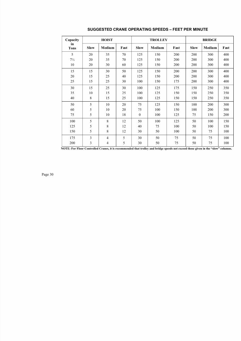
SUGGESTED CRANE OPERATING SPEEDS – FEET PER MINU
HOIST TROLLEY Capacity
in
Tons Slow Medium Fast Slow Medium Fast Slow
5
7½
10
20
20
20
35
35
30
70
70
60
125
125
125
150
150
150
200
200
200
200
200
200
15
20
25
15
15
15
30
25
25
50
40
30
125
125
100
150
150
150
200
200
175
200
200
200
30
35
40
15
10
8
25
15
15
30
25
25
100
100
100
125
125
125
175
150
150
150
150
150
50
60
75
5
5
5
10
10
10
20
20
18
75
75
0
125
100
100
150
150
125
100
100
75
100
125
150
5
5
5
8
8
8
12
12
12
50
40
30
100
75
50
125
100
100
50
50
50
175200
33
44
55
3030
5050
7575
5050
NOTE: For Floor Controlled Cranes, it is recommended that trolley and bridge speeds not exceed those given
Page 30

7/21/2019 Metal Shop - Foundry_handbook
http://slidepdf.com/reader/full/metal-shop-foundryhandbook 33/56
HOISTING ROPE
The following table shows breaking strengths for wire rope commonly used on
cranes, ship hoists & winches.
To obtain the safe working load for each diameter of rope, divide the breaking
strength by the factor of safety. Minimum factor of safety for general use is 5:1. Forhot metal handling equipment and high capacity ship hoists 10:1 is recommended.
Wire rope in daily use should be inspected at least once each week and more
frequently if rope is subjected to heavy duty service. Special attention should be givento sections of rope which pass over sheaves as well as all rope end connections.
A special wire rope lubricant should be applied regularly. When installing newhoist rope, not less than 2 turns should remain on the drum when the load is in its
lowest position to relieve stresses on the rope anchor.
Ultimate Strength In Tons Of Improved Plow Steel Wire Rope
Class 6 x 37
6 Strands, 37 Wires/Strand
Class 6 x l9
6 Strands, 19 Wires/Strand Rope
Diam. Fiber Core
Wire Rope
Core Fiber Core
Wire Rope
Core
3/8”
1/16”
1/2”9/16”
5/8”
3/4”
7/8”
1”
1-1/8”
1-1/4”
5.77
7.82
10.212.9
15.8
22.6
30.6
39.8
50.1
61.5
6.20
8.41
11.013.9
17.0
24.3
32.9
42.8
53.9
66.1
6.10
8.27
10.713.5
16.7
23.8
32.2
41.8
52.6
64.6
6.56
8.89
11.514.5
17.9
25.6
34.6
44.9
56.5
69.4
Page 31

7/21/2019 Metal Shop - Foundry_handbook
http://slidepdf.com/reader/full/metal-shop-foundryhandbook 34/56
SCRAP HANDLING MAGNETS (DEEP COIL)
Diameter, Inches 45” 54” 63” 6
Net Weight, Pounds 2650 4000 6100 77
Head Room Required, Inches 43” 44” 55” 5
Cold Current @ 230 Volts 40 amps. 59 amps. 78 amps. 95 a
Generator Capacity Required 7.5 K.W. 10 K.W. 14 K.W. 17 K
Rectifier Capacity Required 10 K.W. 13.5 K.W. 18 K.W. 22 K
Size of Duplex Flexible Cable #8 B&S #6 B&S #6 B&S #4 B
Recommended Crane Capacity 4 Ton 5 Ton 8 Ton 10
AVERAGE (All Day) LIFTING CAPACITY IN POUNDS
Machine Cast Pig 1500 2560 3970 4
No. 1 Heavy Melting Scrap 1500 2560 3970 4
No. 2 Melting Scrap 1030 1660 2580 3
No. 1 Machinery Scrap (Cast Iron) 815 1300 2040 2
No. 2 Busheling 565 870 1360 1
Steel Turnings 475 725 1230 1
Plate Punchings 1720 3000 4350 5
Page 32

7/21/2019 Metal Shop - Foundry_handbook
http://slidepdf.com/reader/full/metal-shop-foundryhandbook 35/56
GRADES OF MALLEABLE IRON
GradeUltimate
Lbs./Sq. In.
Yield
Lbs./Sq. In.Elongation %
*
***
Cupola32510 (B)
35018 (A)Pearlitic
40,000 (Min.)50,000 (Min.)
53,000 (Min.)60,000 to 90,000
30,000 (Min.)32,500 (Min.)
35,000 (Min.)43,000 to 70,000
5 (Min.)10 (Min.)
18 (Min.)10 to 2
* Grades 32510 and 35018 refer to A.S.T.M. Specification A-47 and are frequently referred to as grades B and A.
** Specifications on mechanical properties for the many special grades of malleable iron are frequently decided
upon by agreement between producer and consumer.
COLOR SCALE FOR TEMPERATURESThe following color scale permits a rough approximation of high temperatures.
Degrees Degrees
Color Centigrade Fahrenheit
Lowest visible red 475 885
Lowest visible red to dark red 475 to 650 885 to 1200
Dark red to cherry red 650 to 750 1200 to 1380
Cherry red to bright cherry red 750 to 815 1380 to 1500
Bright cherry red to orange 815 to 900 1500 to 1650Orange to yellow 900 to 1090 1650 to 2000
Yellow to light yellow 1090 to 1315 2000 to 2400
Light yellow to white 1315 to 1540 2400 to 2800
White to dazzling white 1540 or higher 2800 or higher
FUSION POINTS OF ASH AND SLAGSCoal Ash
Easily fusible below 1200 below 2200
Moderately fusible 1200 to 1430 2200 to 2600
Refractory above 1430 above 2600
Slags
Acid open-hearth slag approx.1250 approx. 2280
Basic open-hearth slag approx. 1250 approx. 2280
Blast furnace slag approx. 1170 approx. 2140Heating furnace slag approx. 1165 approx. 2130
Courtesy Harbison-Walker Refractories Co.
MELTING POINTS OF MINERALS AND OXIDES°Cent. °Fahr.
Corundum (A12O3) 2050 3722Chromium Oxide (Cr 2O3) 1990 3614Cristobalite (SiO2) 1728 3142.4Forsterite (2MgO●SiO2) 1910 3470Lime (CaO) 2570 4658
Periclase (MgO) 2800 5072Rutile (TiO2) 1825 3317Spinel (MgO●A12O3) 2135 3875Zirconia (ZrO2) 2720 4928Zircon (ZrO2●SiO2) 2550 4622
Mullite (3Al2O3●2SiO2)Mullite melts incongruently at 1830°C. (3326°F.) to form corundum and a silicious liquid. It is
completely melted at approximately 1925°C. (3497°F.).Kaolinite (A12O3●2SiO2●2H2O)
Kaolinite has a P.C.E. value of cone 35, corresponding to a temperature of 1785°C. (3245°F.).
Page 33

7/21/2019 Metal Shop - Foundry_handbook
http://slidepdf.com/reader/full/metal-shop-foundryhandbook 36/56
INTERNATIONALATOMIC WEIGHTS
Name Symbol AtomicWeight
Name Symbol AtomicWeight
AluminumAntimony
Argon
Arsenic
Barium
Beryllium
Bismuth
Boron
Cadmium
CalciumCarbon
Cerium
Cesium
Chlorine
Chromium
Cobalt
Copper
Fluorine
GalliumGermanium
Gold
Hydrogen
Iridium
Iron
Lead
Lithium
Magnesium
ManganeseMercury
AlSb
A
As
Ba
Be
Bi
B
Cd
CaC
Ce
Cs
Cl
Cr
Co
Cu
F
GaGe
Au
H
Ir
Fe
Pb
Li
Mg
MnHg
26.98121.75
39.95
74.92
137.34
9.01
208.98
10.81
112.40
40.0812.010
140.12
132.91
35.45
52.00
58.93
63.54
19.00
69.7272.59
196.97
1.0080
192.2
55.85
207.19
6.940
24.31
54.94200.59
Molybdenum Nickel
Niobium
Nitrogen
Osmium
Oxygen
Palladium
Phosphorus
Platinum
PotassiumRadium
Selenium
Silicon
Silver
Sodium
Strontium
Sulfur
Tantalum
TelluriumThallium
Thorium
Tin
Titanium
Tungsten
Uranium
Vanadium
Yttrium
ZincZirconium
Mo Ni
Nb
N
Os
O
Pd
P
Pt
KRa
Se
Si
Ag
Na
Sr
S
Ta
TeTi
Tb
Sn
Ti
W
U
V
Yt
ZnZr
95.9458.71
92.91
14. 008
190.2
16.000
106.4
30.97
195.09
39.10226
78.96
28.09
107.87
22.99
87.62
32.06
180.95
127.60204.37
232.04
118.69
47.90
183.85
238.03
50.94
88.90
65.3791.22
Page 34

7/21/2019 Metal Shop - Foundry_handbook
http://slidepdf.com/reader/full/metal-shop-foundryhandbook 37/56
PROPERTIES OF VARIOUS METALS AND ALLOYS
Density
Specific
Heat
(RoomTemp)
Melting Point
Linear
LengthMetal Symbol
g/cm3 lbs./in.
3 Cal./g/°C °C °F per °
AluminumBrass YellowBronzeBronze CastCadmium
ChromiumCobaltCopperGold
Iron (Cast)Iron (Wrought)LeadMagnesiumManganese
Monel NickelSiliconSilverSteel:
CarbonStainl. 304Stainl. 410
TinTitanium
UraniumZinc
Al
–
–
–
Cd
Cr
Co
Cu
Au
–
Fe
Pb
Mg
Mn
–
Ni
Si
Ag
Sn
Ti
U
Zn
2.708.20-8.608.80-8.78
8.788.648
6.938.718.8919.32
7.03-7.737.8711.361.747.43
8.848.902.33
10.49
7.87.97.7
7.304.51
19.077.13
0.0980.296-0.3100.318-0.317
0.3170.312
0.2500.3150.3210.698
0.254-0.2790.2840.4100.0630.268
0.3190.3220.084
0.379
0.2820.2850.278
0.2640.163
0.6890.258
0.2150.090.090.090.055
0.110.0990.0920.031
0.110.110.031
0.2450.121
0.1270.1050.162
0.056
0.1170.120.11
0.0540.124
0.0280.091
660931
10461050321
1878149710841064
1088-12601510327
6501260
132714551412
962
1482> 1399> 1482
2321670
1132419
1220170819151922610
34122727
19831947
1990-23002750621
12022300
242126512574
1764
2700> 2550> 2700
4503038
2070786
23.6x120.318.418.429.8
6.213.816.814.2
10.611.429.327.123.3
14.013.3 –
19.7
11.017.311.0
238.4
–39.7

7/21/2019 Metal Shop - Foundry_handbook
http://slidepdf.com/reader/full/metal-shop-foundryhandbook 38/56
THERMAL PROPERTIES OF METALS
SUBSTANCE
Mean
Specific
Heat
60° to
MeltingPoint
BTU per
Lb. Per
°F
Melting
Point
°F
Heat inSolid at
Melting
Point
BTU/Lb.
LatentHeat
of
Fusion
BTU/Lb.
Total
Heat
in Liquidat
Melting
Temp.
BTU/Lb.
Average
Pouring
Temp.
°F
Total
Heat
in Liquid
atPouring
Temp.
°F
BTU/Lb.
Aluminum .254 1220 288 170 458 1380 500
Antimony .054 1167 58.5 68.9 127 1320 136
Beryllium .634 2343 1411 470 1881 2500 1981
Bismuth .032 520 14.0 22.5 36.5 620 40.1
Brass, Muntz Metal (60 Cu, 40 Zn) .120 1660 192 69.0 261 1850 284
Brass, Red (85 Cu, 15 Zn) .105 1880 191 86.5 278 2250 317
Brass, Yellow (65 Cu, 35 Zn) .106 1708 175 84.4 259 2150 306
Bronze, Aluminum (90 Cu, 10 Al) .126 1905 232 98.6 331 2200 368
Bronze, Bearing (80 Cu, 10 Sn, 10 Pb) .095 1832 168 79.9 248 2050 269
Bronze, Bell-Metal .100 1598 154 76.3 230 1900 260
Bronze, Gun-Metal .107 1832 190 84.2 274 2100 303
Bronze, Tobin .107 1625 167 73.5 241 1850 265
Cadmium .060 610 31.3 23.8 55.1 750 65.1
Chromium .156 3412 525 136 661
Copper .105 1983 197 91.1 288 2200 321
Gold .034 1947 62.9 29.0 91.9 2150 100.3
Iron, Pure 60° to 2802°F .168 2802 451 117 568 3100 626
Iron, Pure 60° to 2554°F .168 409* 3.06 412**
Iron, Pure 60° to 1670°F .164 254* 6.53 261**
Iron, Pure 60° to 1414°F .141 184* 0.0 184**
Iron, Cast, Gray (94 Fe, 3.5 C, 2.5 Si) .190 2246 415 41.1 456 2800 583
Iron, Cast, White (97 Fe, 3 C) .180 2102 368 60.3 428 2900 612
Iron, Pig (4.22 C, 1.48 Si, 0.73 Mn,0.12 P, 0.03 S)
.153 2012 299 84.6 384 2300 450
Lead .032 621 17.4 11.3 28.7 720 31.9
Magnesium .281 1202 312 160 472 1380 522
Manganese .182 2300 391 115 506 2400 529
Molybdenum .078 4760 372 126 498
Monel Metal .127 2421 305 122 427 2750 464
Nickel .136 2651 346 133 479 2850 506
Platinum .037 3224 116 49 165
Rhodium .076 3571 262
Silver .062 1764 103 45 148 1950 160
Steel (0.00-0.60 C) .165 2800 445 118 563 3100 621
Steel (0.60-0.80 C) .165 2670 425 118 543 2950 644
Steel (0.80-1.00 C) .165 2600 421 118 539 2900 608
Tin .059 450 21.5 26.1 47.6 650 59.5
Titanium (99.9 Ti) .173 3038 295 100 395
Tungsten .036 6170 220 79 299Vanadium .153 3150 473
Zinc .101 786 70.9 43.4 114 900 125
Zirconium .066 3200 207
* Heat in solid up to transformation point
** Heat in solid after allotropic point
Page 36

7/21/2019 Metal Shop - Foundry_handbook
http://slidepdf.com/reader/full/metal-shop-foundryhandbook 39/56
Specific Gravity – Density
Gas or VaporChemical
Formula
Specific
Gravity
Air = 1
D
Lb
1 A
Acetylene C2H2 0.9073
Air – 1.0000
Ammonia NH3 0.5963
Butane C4H10 2.0854
Carbon Dioxide CO2 1.5290
Carbon Monoxide CO 0.9671 Ethane C2H6 1.0493
Ethylene C2H4 0.9749
Helium He 0.1380
Hydrogen H2 0.0695
Methane CH4 0.5544
Nitrogen N2 0.9672
Oxygen O2 1.10527
Ozone O3 1.6580
Propane C3H8 1.5620
Sulfur Dioxide SO2 2.2638
PHYSICAL PROPERTIESOF GASES AND VAPORS

7/21/2019 Metal Shop - Foundry_handbook
http://slidepdf.com/reader/full/metal-shop-foundryhandbook 40/56
PROPERTIES OF DRY AIR
Temp.
Deg. F.
Density,
lb./cu. ft.
Wolume of
1 lb. Dry
Air, cu. ft.
Fraction of
Volume*
Enthalpy
BTU/lb.
0
510
1520
25
303540
455055
60
6570
758085
90
95100
110
120130
140150
160
170
180190
200220240
260
280300
350400
450
500550600
700800900
1000
1200
150018002100
.0863
.0854
.0845
.0836
.0827
.0819
.0810
.0802
.0794
.0786
.0778
.0771
.0764
.0756
.0749
.0742
.0735
.0728
.0722
.0715
.0709
.0696
.0684
.0673
.0662
.0651
.0640
.0630
.0620
.0614
.0601
.0584
.0567
.0551
.0536
.0522
.0490
.0461
.0436
.0413
.0393
.0374
.0342
.0315
.0292
.0272
.0239
.0202
.0175
.0155
11.59
11.7111.83
11.9612.09
12.21
12.3512.4712.59
12.7212.8512.97
13.09
13.2313.35
13.4813.61
13.74
13.8513.9914.10
14.37
14.6214.86
15.1115.36
15.63
15.87
16.1316.29
16.6417.1217.64
18.1518.66
19.16
20.4121.69
22.94
24.2125.4526.74
29.2431.7534.25
36.76
41.84
49.5057.1464.52
. 868
.877
.886
.896
.905
.915
.924
.934
.943
.953
.962
.971
.981
.9901.000
1.0091.0191.028
1.038
1.0471.057
1.075
1.0941.113
1.1321.151
1.170
1.189
1.2081.227
1.2451.2831.321
1.359
1.3961.434
1.5281.623
1.717
1.8111.9062.001
2.1902.3782.567
2.756
3.133
3.7104.2784.834
109.90
111.10112.30
113.50114.69
115.89
117.08118.28119.48
120.68121.87123.07
124.27
125.47126.66
127.86129.06130.26
131.46
132.66133.86
136.26
138.66141.06
143.47145.88
148.28
150.68
153.09155.50
157.92162.73167.56
172.39
177.23182.08
194.25206.46
218.72
231.06243.48255.96
281.14306.65332.48
358.63
411.82
493.64577.51662.99
* Fraction of volume at 70°F or relative volume compared to 70°F (must multiply by 100 for % volume.)
Page 38

7/21/2019 Metal Shop - Foundry_handbook
http://slidepdf.com/reader/full/metal-shop-foundryhandbook 41/56
TEMPERATURE CONVERSION TABLE NOTE: The Fahrenheit equivalent is shown in the bold type to the right of the Centigrade temperature C.
The Centigrade equivalent is shown in the bold type to the left of the Fahrenheit temperature F.C. F. C. F. C. F. C. F.
-17.8
-17.2
-16.7-16.1
-15.6-15.0
-14.4
-13.9
0
1
2
3
45
6
7
32.0
33.8
35.637.4
39.241.0
42.8
44.6
4.44
5.00
5.566.11
6.677.22
7.78
8.33
40
41
42
43
4445
46
47
104.0
105.8107.6
109.4
111.2113.0
114.8
116.6
26.7
27.227.8
28.3
28.929.4
30.0
30.6
80
81
82
83
8485
86
87
176.0
177.8179.6
181.4
183.2185.0
186.8188.6
149
154160
166
171177
182188
300
310
320
330
340350
360
370
572
590608
626
644662
680698
-13.3
-12.8
-12.2
-11.7-11.1
-10.6
-10.0
-9.44
8
9
10
11
12
13
14
15
46.4
48.2
50.0
51.853.6
55.4
57.2
59.0
8.89
9.44
10.0
10.611.1
11.7
12.2
12.8
48
49
50
51
52
53
54
55
118.4
120.2
122.0
123.8125.6
127.4
129.2
131.0
31.1
31.7
32.2
32.833.3
33.9
34.4
35.0
88
89
90
91
92
93
94
95
190.4
192.2
194.0
195.8197.6
199.4
201.2
203.0
193
199
204
210216
221
227
232
380
390
400
410
420
430
440
450
716
734
752
770788
806
824
842
-8.89-8.33
-7.78
-7.22
-6.67
-6.11-5.56
-5.00
16
17
18
19
20
21
22
23
60.862.6
64.4
66.2
68.0
69.871.6
73.4
13.313.9
14.4
15.0
15.6
16.116.7
17.2
56
57
58
59
60
61
62
63
132.8134.6
136.4
138.2
140.0
141.8143.6
145.4
35.636.1
36.7
37.2
38
4349
54
96
97
98
99
100
110
120
130
204.8206.6
208.4
210.2
212
230248
266
238243
249
254
260
266271
277
460
470
480
490
500
510
520
530
860878
896
914
932
950968
986
-4.44
-3.89
-3.33-2.78
-2.22
-1.67
-1.11
-0.56
2425
26
27
28
29
30
31
75.2
77.0
78.880.6
82.4
84.2
86.0
87.8
17.8
18.3
18.919.4
20.0
20.6
21.1
21.7
6465
66
67
68
69
70
71
147.2
149.0
150.8152.6
154.4
156.2
158.0
159.8
60
66
7177
82
88
93
99
140150
160
170
180
190
200
210
284
302
320338
356
374
392
410
282
288
293299
304
310
316
321
540550
560
570
580
590
600
610
1004
1022
10401058
1076
1094
1112
1130
0
0.56
1.11
1.67
2.222.78
3.33
3.89
32
33
34
35
36
37
38
39
89.6
91.4
93.2
95.0
96.898.6
100.4
102.2
22.2
22.8
23.3
23.9
24.425.0
25.6
26.1
72
73
74
75
76
77
78
79
161.6
163.4
165.2
167.0
168.8170.6
172.4
174.2
104
110
116
121127
132
138
143
220
230
240
250
260
270
280
290
428
446
464
482500
518
536
554
327
332
338
343349
354
360
366
620
630
640
650
660
670
680
690
1148
1166
1184
12021220
1238
1256
1274
C. F. C. F. C. F. C. F.
371
377
382388
393399
404
410
700
710
720
730
740
750
760
770
1292
1310
13281346
13641382
1400
1418
593
599
604610
616621
627
632
1100
1110
1120
1130
1140
1150
1160
1170
2012
2030
20482066
20842102
2120
2138
816
821
827832
838843
849
854
1500
1510
1520
1530
1540
1550
1560
1570
2732
2750
27682786
28042822
2840
2858
1038
1043
10491054
10601066
1071
1077
1900
1910
1920
1930
1940
1950
1960
1970
3452
3470
34883506
35243542
3560
3578
416
421
427
432
438443
449
454
780
790
800
810
820
830
840
850
1436
1454
1472
1490
15081526
1544
1562
638
643
649
654
660666
671
677
1180
1190
1200
1210
1220
1230
1240
1250
2156
2174
2192
2210
22282246
2264
2282
860
866
871
877
882888
893
899
1580
1590
1600
1610
1620
1630
1640
1650
2876
2894
2912
2930
29482966
2984
3002
1082
1088
1093
1099
11041110
1116
1121
1980
1990
2000
2010
2020
2030
2040
2050
3596
3614
3632
3650
36683686
3704
3722
460
466
471
477
482
488
493
499
860
870
880
890
900
910
920
930
1580
1598
1616
1634
1652
1670
1688
1706
682
688
693
699
704
710
716
721
1260
1270
1280
1290
1300
1310
1320
1330
2300
2318
2336
2354
2372
2390
2408
2426
904
910
916
921
927
932
938
943
1660
1670
1680
1690
1700
1710
1720
1730
3020
3038
3056
3074
3092
3110
3128
3146
1127
1132
1138
1143
1149
1154
1160
1166
2060
2070
2080
2090
2100
2110
2120
2130
3740
3758
3776
3794
3812
3830
3848
3866
504510
516521
527
532
538
543
940950
960
970
980
990
1000
1010
17241742
17601778
1796
1814
1832
1850
727732
738743
749
754
760
766
13401350
1360
1370
1380
1390
1400
1410
24442462
24802498
2516
2534
2552
2570
949954
960966
971
977
982
988
17401750
1760
1770
1780
1790
1800
1810
31643182
32003218
3236
3254
3272
3290
11711177
11821188
1193
1199
1204
1210
21402150
2160
2170
2180
2190
2200
2210
38843902
39203938
3956
3974
3992
4010
549
554
560
566
571577
582
588
1020
1030
1040
1050
1060
1070
1080
1090
1868
1886
1904
1922
19401958
1976
1994
771
777
782
788
793799
804
810
1420
1430
1440
1450
1460
1470
1480
1490
2588
2606
2624
2642
26602678
2696
2714
993
999
1004
1010
1016
1021
1027
1032
1820
1830
1840
1850
1860
1870
1880
1890
3308
3326
3344
3362
3380
3398
3416
3434
1216
1221
1227
1232
1238
1243
1249
1254
2220
2230
2240
2250
2260
2270
2280
2290
4028
4046
4064
4082
4100
4118
4136
4154
Page 39

7/21/2019 Metal Shop - Foundry_handbook
http://slidepdf.com/reader/full/metal-shop-foundryhandbook 42/56
USEFUL FORMULAS
MECHANICAL FORMULAS
Torque in Lb.-ft. = RPM
Hp 5250× Hp =
5250
RPM Torque×
Rpm = Polesof No
Frequency .
120×
Horsepower =12000,33
)(2)(
×
××× RPM inches R pounds P π
Horsepower =000,63
RPM R P ×× or
000,63
RPM Torque×
1 KW = 1.341 HP 1 HP = 0.7457 KW
TORQUE (LB.-IN.) AT 1 HP
RPM LB.-IN RPM LB.-IN RPM LB.-IN RPM LB.-IN
17501430
1170950870780640580520420
3644
5466728198109121150
350280
230190155125100846856
180225
2743314065046307509261125
4537
302520
16.513.5119
7.5
14001703
21002520315038184667572770008400
64.7
4.03.22.72.21.81.51.21.0
1050013404
1575019687233702863635000420005250063000
To compute torque at any horsepower, multiply torque values above by horsepower required.Examples: 10 hp @ 350 rpm, Torque = 10 x 180 or 18000 lb.-in.
½ hp @ 30 rpm, Torque = ½ x 2100 or 1050 lb.-in.
For intermediate speeds, approximate the torque from table, or apply standard torque formula above.
ELECTRICAL FORMULAS
Alternating Current
To Find Single-phase Three-phase
Amperes whenhorsepower is known pf Eff E
Hp
××
× 746
pf Eff E
Hp
×××
×
73.1
746
Amperes whenkilowatts are known pf E
Kw
×
×1000
pf E
Kw
××
×
73.1
1000
Amperes whenkva are known E
Kva 1000×
E
Kva 1000×
Kilowatts1000
pf E I ××
1000
73.1 pf E I ×××
Kva1000
E I ×
1000
73.1 E I ××
Horsepower –(output) 1000
pf Eff E I ×××
1000
73.1 pf Eff E I ××××
I = Amperes; E = Volts; Eff. = Efficiency; pf= Power factor; Kva = Kilovolt-amperes; Kw = Kilowatts
RULES OF THUMB (Approximation) At 1800 rpm, a motor develops 3 lb.-ft. per hp At 1200 rpm, a motor develops 4.5 lb.-ft. per hpAt 575 volts, a 3-phase motor draws 1 amp per hp At 460 volts, a 3-phase motor draws 1.25 amp per hpAt 230 volts, a 3-phase motor draws 2.5 amp per hp At 230 volts, a single-phase motor draws 5 amp per hp
At 115 volts, a single-phase motor draws 10 amp per hp
Page 40

7/21/2019 Metal Shop - Foundry_handbook
http://slidepdf.com/reader/full/metal-shop-foundryhandbook 43/56
WEIGHTS OF VARIOUS MATERIALS
Material
Average per cubic
foot in pounds
Material
Average per cubic
foot in pounds
BrickCommon
Cements
Portland
Coal and Coke
AnthraciteBituminousCharcoal
Coke
Concrete
Cement, fine
Rubble, coarse
Earth
Loam, dry, loose
Loam, packedLoam, soft loose mudLoam, dense mud
Gravel
Dry, packedWet, packed
Lime
Quick, loose lumpsQuick, fineStone, large rocks
Stone, irregular lumps
Masonry
Dry
Granite or limestoneMortar, rubbleSandstone, dressed
Metals
AluminumBrass, castBronzeCopper, cast
Copper, rolled or wireIron, gray cast
Iron, white castIron, wrought
100
94
6049
18.5
26.3
137
119
76
95108125
118130
5375
168
96
138
165154144
166524
548537
555445475490
Metals (Cont’d)Lead, cast
Lead, rolled NickelSteel, castSteel, rolled
Steel, stainlessTin, castZinc, cast
Oils
CrudeEngineGasoline
Petroleum
Refractory Materials
Firebrick, insulating
Firebrick material(superplastic)
Fireclay brick(superduty)
Ganister, ground silicaMagnesite and magnesite-
chrome brickMagnesite (loose)
Silica brick
Sand
Dry, loose
Dry, packed
Water
At 39.2°F (Max density)
Woods, Dry
HemlockHickory
IronwoodMahogany
MapleOak, liveOak, white
Pine, whitePine, yellow northernPine, yellow southernSpruce
708711537490495
473 - 516455443
485543
55
30 - 60
135
137 - 154
123
170 - 197155
102 - 115
100
110
62.425
25
53114
35 - 53495950
25344525
Page 41

7/21/2019 Metal Shop - Foundry_handbook
http://slidepdf.com/reader/full/metal-shop-foundryhandbook 44/56
PRESSURE EQUIVALENTS
Ounces per
Sq. In.
Lbs per
Sq. In.
Inchesof
Water
Millimetersof
Water
Inchesof
Mercury
Millimetersof
Mercury
0.250.50
1
23
4
56
7
89
101112
13
14
1516
17
1819
20
2122
23
24
2526
27
2829
30
31
3233
3435
0.0160.031
0.062
0.1250.187
0.250
0.3120.375
0.437
0.5000.562
0.6250.6870.750
0.812
0.875
0.9371.000
1.062
1.1251.187
1.250
1.3121.375
1.437
1.500
1.5621.625
1.687
1.7501.812
1.875
1.937
2.0002.062
2.1252.187
0.4330.866
1.732
3.4645.20
6.92
8.6610.39
12.12
13.8615.59
17.3219.0520.78
22 52
21 25
25 9827 71
29.44
31.1832.91
34.64
36.3738.10
39.84
41.57
43.3045.00
46.8
48.550.2
52.0
53.7
55.457.2
58.960.6
11.0022.00
44.00
88.0132.0
176.0
220.0264.0
308.0
350.9395.0
439.0483.0527.0
571
615
659703
747
791835
879
923967
1011
1055
10991143
1187
12311275
1319
1363
14071451
14951539
0.03190.0638
0.1275
0.25510.3826
0.570
0.6380.765
0.893
1.0201.148
1.2751.4031.531
1.658
1.786
1.9132.041
2.169
2.2962.424
2.551
2.6792.806
2.934
3.061
3.1893.317
3.444
3.5723.699
3.827
3.954
4.084.21
4.344.46
0.8101.621
3.239
6.4789.72
12.95
16.1919.43
22.67
25.9129.15
32.3835.6238.86
42.1
45.3
48.651.8
55.1
58.361.5
64.8
68.071.2
74.5
77.7
81.084.2
87.4
90.793.9
97.2
100.4
103.6106.9
110.1113.3
Page 42

7/21/2019 Metal Shop - Foundry_handbook
http://slidepdf.com/reader/full/metal-shop-foundryhandbook 45/56
METRIC EQUIVALENTS(Based on National Bureau of Standards)
LENGTH
cm = 0.3937 in. in. = 2.5400 cmm = 3.2808 ft. ft. = 0.3048 m
m = 1.0936 yd. yd. = 0.9144 mkm = 0.6213 mile mile = 1.6093 km
AREA
cm2 = 0.1549 in.
2 in.
2 = 6.4516 cm
2
m2 = 10.7638 ft.
2 ft.
2 = 0.0929 m
2
m2 = 1.1959 yd.
2 yd.
2 = 0.7645 m
2
km2 = 0.3861 mi.
2 mi.
2 = 2.5900 km
2
hectare = 2.471 acres acres = 0.4047 hectareone hectare = 10,000 m
2
VOLUMEcm
3 = 0.0610 in.
3 in.
3 = 16.3871 cm
3
m3 = 35.3142 ft.
3 ft.
3 = 0.0283 m
3
m3 = 1.3079 yd.
3 yd.
3 = 0.7645 m
3
Liter = 0.0353 ft.3
ft.3
= 28.32 liters
Liter = 0.2641 gal. (U.S.) gal. = 3.7853 liters
Liter = 61.0250 in.3 in.
3 = 0.0163 liters
one Liter of pure water @ 4°C = 2.2046 lb. = 1 kg
WEIGHT g = 15.4323 grains grain = 0.0647 g
g = 0.0352 oz. oz. = 28.3496 gkg = 2.2046 lbs. lb. = 0.4535 kg
kg = 0.0011 ton (short) ton (short) = 907.1848 kgm ton = 1.1023 ton (short) ton (short) = 0.9071 m ton
m ton = 2205 lbs. ton (long) = 1016 kg
PRESSURE 1 kg per cm
2 = 14.22 lb. per in.
2 1 lb. per in.
2 = 0.07031 kg per cm
2
1 kg per m2 = 0.2048 lb. per ft.
2 1 lb. per ft.
2 = 4.882 kg per m
2
1 kg per cm2 = 0.9678 normal atmosphere
1 normal atmosphere = 1.0332 kg per cm2
1 normal atmosphere = 14.70 lb. per in.2
MISCELLANEOUS Density = 1 lb./ft.
3 = 16.0185 kg/m
3
Energy = 1 BTU = 0.252 kg-calorie
Work = 1 ft. lb. = 0.13826 kg-m
Density = 1 KW = 14.3328 kg-Cal/min.
Page 43

7/21/2019 Metal Shop - Foundry_handbook
http://slidepdf.com/reader/full/metal-shop-foundryhandbook 46/56
CONVERSION FACTORS
BTU per min. x 0.02356 = HorsepowerBTU per min. x 0.01757 = Kilowatts
Ft. Lbs. per min. x 0.0000303 = HorsepowerHorsepower x 42.44 = BTU per min
Horsepower x 33,000 = Ft. Lbs. per minHorsepower x 10.70 = kg cal per min.
Horsepower x 745.7 = WattsWatts x 0.7373 = Ft. Lbs. per sec.
Kilowatts x 1.3410 = HorsepowerInches of Water x 0.5773 = Oz. per Sq. In.
Oz. per Sq. In. x 1.732 = In. of WaterIn. of Water x 0.03613 = P.S.I.U.S. Gallons x 0.8327 = Imperial GallonsU.S. Gallons x 0.1337 = Cubic Ft.
In. of Mercury x 0.4912 = P.S.I.Ft. of Water x 0.4335 = P.S.I.Cu. Ft. x 62.428 = Pounds of WaterU.S. Gallons x 8.336 = Pounds of Water
BTU per Lb. x 0.586 = KWH per Ton (Short)
Cal per g x 1.8 = BTU per Poundg per cm x 62.428 = Pounds per Ft.M.P.H. x 88 = Ft. per Sec.Diameter Circle x 0.886 = Side of Equal Square
Side of Square x 1.414 = DiagonalSide of Cube x 1.732 = Space DiagonalJoule x 0.7373 = Foot PoundsMiles x 5,280 = Feet
Long Tons x 2,240 = PoundsAcres x 43,560 = Sq. Ft.Lbs. x 7,000 = Grains
POWER1 KW = 56.87 BTU per min.
1 KW = 1.341 HP1 HP = 550 Ft.-Lb. per sec.
1 Watt = 44.25 Ft.-Lb. per min.
1 Watt = 14.34 g-cal per min.
TEMPERATURE SCALESDegrees Fahrenheit = 1.8 (Deg C) + 32
Degrees Kelvin = Deg C + 273.16
Degrees Rankine = Deg F + 459.69
ENERGY1 BTU = 252.161 Calories
1 HP-HR = 2544.48 BTU
1 KWH = One KW for one our1 KWH = 2,655,218 Ft.-Lb.
1 KWH = 1.34 HP-HR
1 KWH = 3412.19 BTU
COST OF OPERATING ELECTRIC MOTORSOne KWH is consumed for each one (1) HP used per hour. Calculate HP used per hour and multiply
by prevailing rate per KWH to get cost of operation.
(Above is based on a motor efficiency of 85% and average line loss.)
Page 44
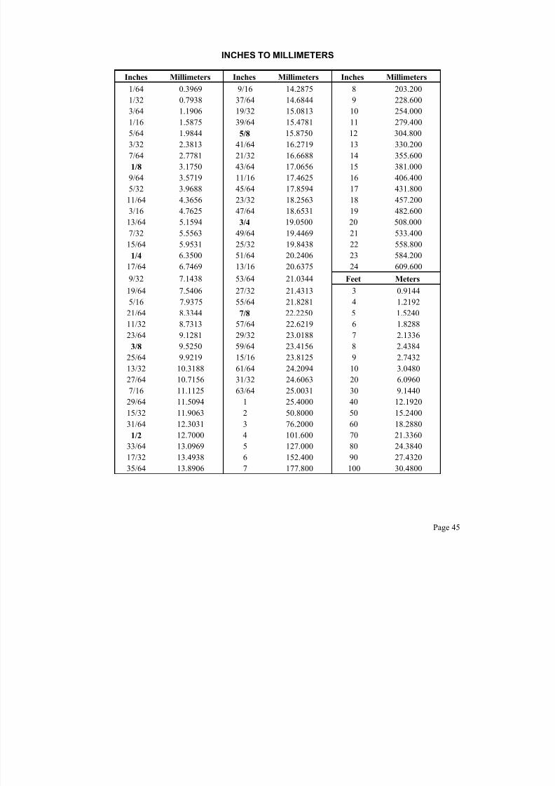
7/21/2019 Metal Shop - Foundry_handbook
http://slidepdf.com/reader/full/metal-shop-foundryhandbook 47/56
INCHES TO MILLIMETERS
Inches Millimeters Inches Millimeters Inches Millimeters
1/64 0.3969 9/16 14.2875 8 203.200
1/32 0.7938 37/64 14.6844 9 228.600
3/64 1.1906 19/32 15.0813 10 254.000
1/16 1.5875 39/64 15.4781 11 279.400
5/64 1.9844 5/8 15.8750 12 304.800
3/32 2.3813 41/64 16.2719 13 330.200
7/64 2.7781 21/32 16.6688 14 355.600
1/8 3.1750 43/64 17.0656 15 381.000
9/64 3.5719 11/16 17.4625 16 406.400
5/32 3.9688 45/64 17.8594 17 431.800
11/64 4.3656 23/32 18.2563 18 457.200
3/16 4.7625 47/64 18.6531 19 482.60013/64 5.1594 3/4 19.0500 20 508.000
7/32 5.5563 49/64 19.4469 21 533.400
15/64 5.9531 25/32 19.8438 22 558.800
1/4 6.3500 51/64 20.2406 23 584.200
17/64 6.7469 13/16 20.6375 24 609.600
9/32 7.1438 53/64 21.0344 Feet Meters
19/64 7.5406 27/32 21.4313 3 0.9144
5/16 7.9375 55/64 21.8281 4 1.2192
21/64 8.3344 7/8 22.2250 5 1.5240
11/32 8.7313 57/64 22.6219 6 1.8288
23/64 9.1281 29/32 23.0188 7 2.1336
3/8 9.5250 59/64 23.4156 8 2.4384
25/64 9.9219 15/16 23.8125 9 2.7432
13/32 10.3188 61/64 24.2094 10 3.0480
27/64 10.7156 31/32 24.6063 20 6.0960
7/16 11.1125 63/64 25.0031 30 9.1440
29/64 11.5094 1 25.4000 40 12.1920
15/32 11.9063 2 50.8000 50 15.2400
31/64 12.3031 3 76.2000 60 18.28801/2 12.7000 4 101.600 70 21.3360
33/64 13.0969 5 127.000 80 24.3840
17/32 13.4938 6 152.400 90 27.4320
35/64 13.8906 7 177.800 100 30.4800
Page 45

7/21/2019 Metal Shop - Foundry_handbook
http://slidepdf.com/reader/full/metal-shop-foundryhandbook 48/56
MEASURES AND WEIGHTS
DECIMAL OF AN INCH AND A FOOT
Fractions
Of Inch of Foot
I n c h E q u i v a -
l e n t s t o F
o o t
F r a c t i o n
s
Fractions
Of Inch of Foot
I n c h E q u i v a -
l e n t s t o F
o o t
F r a c t i o n
s
Fractions
Of Inch of Foot
I n c h E q u i v a -
l e n t s t o F
o o t
F r a c t i o n
s
Fractions
Of Inch of Foot
I n c h E q u i v a -
l e n t s t o F
o o t
F r a c t i o n
s
0.0052 1/16 0.2552 3 1/16 0.5052 6 1/16 0.7552 9 1/160.0104 1/8 0.2604 3 1/8 0.5104 6 1/8 0.7604 9 1/8
1/64 0.015625 3/16 17/64 0.265625 3 3/16 33/64 0.515625 6 3/16 49/64 0.765625 9 3/160.0208 1/4 0.2708 3 1/4 0.5208 6 1/4 0.7708 9 1/40.0260 5/16 0.2760 3 5/16 0.5260 6 5/16 0.7760 9 5/16
1/32 0.03125 3/8 9/32 0.28125 3 3/8 17/32 0.53125 6 3/8 25/32 0.78125 9 3/80.0365 7/16 0.2865 3 7/16 0.5365 6 7/16 0.7865 9 7/160.0417 1/2 0.2917 3 1/2 0.5417 6 1/2 0.7917 9 1/2
3/64 0.046875 9/16 19/64 0.296875 3 9/16 35/64 0.546875 6 9/16 51/64 0.796875 9 9/160.0521 5/8 0.3021 3 5/8 0.5521 6 5/8 0.8021 9 5/80.0573 11/16 0.3073 3 11/16 0.5573 6 11/16 0.8073 9 11/16
1/16 0.06250 3/4 5/16 0.31250 3 3/4 9/16 0.56250 6 3/4 13/16 0.81250 9 3/40.0677 13/16 0.3177 3 13/16 0.5677 6 13/16 0.8177 9 13/160.0729 7/8 0.3229 3 7/8 0.5729 6 7/8 0.8229 9 7/8
5/64 0.078125 15/16 21/64 0.328125 3 15/16 37/64 0.578125 6 15/16 53/64 0.828125 9 15/160.0833 1 0.3333 4 0.5833 7 0.8333 100.0885 1 1/16 0.3385 4 1/16 0.5885 7 1/16 0.8385 10 1/16
3/32 0.09375 1 1/8 11/32 0.34375 4 1/8 19/32 0.59375 7 1/8 27/32 0.84375 10 1/80.0990 1 3/16 0.3490 4 3/16 0.5990 7 3/16 0.8490 10 3/160.1042 1 1/4 0.3542 4 1/4 0.6042 7 1/4 0.8542 10 1/4
7/64 0.109375 1 5/16 23/64 0.359375 4 5/16 39/64 0.609375 7 5/16 55/64 0.859375 10 5/160.1146 1 3/8 0.3646 4 3/8 0.6146 7 3/8 0.8646 10 3/80.1198 1 7/16 0.3698 4 7/16 0.6198 7 7/16 0.8698 10 7/16
1/8 0.12500 1 1/2 3/8 0.37500 4 1/2 5/8 0.62500 7 1/2 7/8 0.87500 10 1/20.1302 1 9/16 0.3802 4 9/16 0.6302 7 9/16 0.8802 10 9/160.1354 1 5/8 0.3854 4 5/8 0.6354 7 5/8 0.8854 10 5/8
9/64 0.140625 1 11/16 25/64 0.390625 4 11/16 41/64 0.640625 7 11/16 57/64 0.890625 10 11/160.1458 1 3/4 0.3958 4 3/4 0.6458 7 3/4 0.8958 10 3/40.1510 1 13/16 0.4010 4 13/16 0.6510 7 13/16 0.9010 10 13/16
5/32 0.15625 1 7/8 13/32 0.40625 4 7/8 21/32 0.65625 7 7/8 29/32 0.90625 10 7/80.1615 1 15/16 0.4115 4 15/16 0.6615 7 15/16 0.9115 10 15/160.1667 2 0.4167 5 0.6667 8 0.9167 11
11/64 0.171875 2 1/16 27/64 0.421875 5 1/16 43/64 0.671875 8 1/16 59/64 0.921875 11 1/160.1771 2 1/8 0.4271 5 1/8 0.6771 8 1/8 0.9271 11 1/80.1823 2 3/16 0.4323 5 3/16 0.6823 8 3/16 0.9323 11 3/16
3/16 0.18750 2 1/4 7/16 0.43750 5 1/4 11/16 0.68750 8 1/4 15/16 0.93750 11 1/40.1927 2 5/16 0.4427 5 5/16 0.6927 8 5/16 0.9427 11 5/160.1979 2 3/8 0.4479 5 3/8 0.6979 8 3/8 0.9479 11 3/8
13/64 0.203125 2 7/16 29/64 0.453125 5 7/16 45/64 0.703125 8 7/16 61/64 0.953125 11 7/160.2083 2 1/2 0.4583 5 1/2 0.7083 8 1/2 0.9583 11 1/20.2135 2 9/16 0.4635 5 9/16 0.7135 8 9/16 0.9635 11 9/16
7/32 0.21875 2 5/8 15/32 0.46875 5 5/8 23/32 0.71875 8 5/8 31/32 0.96875 11 5/80.2240 2 11/16 0.4740 5 11/16 0.7240 8 11/16 0.9740 11 11/160.2292 2 3/4 0.4792 5 3/4 0.7292 8 3/4 0.9792 11 3/4
15/64 0.234375 2 13/16 31/64 0.484375 5 13/16 47/64 0.734375 8 13/16 63/64 0.984375 11 13/160.2396 2 7/8 0.4896 5 7/8 0.7396 8 7/8 0.9896 11 7/80.2448 2 15/16 0.4948 5 15/16 0.7448 8 15/16 0.9948 11 15/16
1/4 0.25000 3 1/2 0.50000 6 3/4 0.75000 9 1 1.00000 12
Page 46

7/21/2019 Metal Shop - Foundry_handbook
http://slidepdf.com/reader/full/metal-shop-foundryhandbook 49/56

7/21/2019 Metal Shop - Foundry_handbook
http://slidepdf.com/reader/full/metal-shop-foundryhandbook 50/56
INDEXAir, dry, properties of 38
Air, Humidity percentages 16
Atomic weights 34
Circles, area and circumstances 47
Coke consumption due to moisture 17
Color scale for temperatures 33Combustion, air required for 12,13
Combustion, useful data 23
Conversion factors 44
Crane Speeds 30
Crane hoisting rope, size and strength 31
Cupolas, formula for estimating height of bed coke 15
Cupolas, front slagging 11
Cupolas, melting rates for lined 4
Cupolas, melting rates for liningless hot blast 5
Cupolas, planning new installations 2
Cupolas, operation, pointers on 3
Cupolas, recommended tap hole sizes 10
Cupolas well, holding capacities 15
Cupolas lining data 6, 7, 8, 9
Decimal equivalents 46
Electric Arc furnace transformers 19
Electrical motors, cost of operating 44
Electrodes, Graphite 19
Energy 44
Formulas, mechanical, electrical, rules of thumb 40
Fusion, points, ash and slag 33
Gases and vapors, physical properties 37
Hydro-Arc furnace data, power consumption 20
Hydro-Arc furnace, Shell capacities 18
Inches to Millimeters 45
Induction furnace, vertical type 21
Induction furnace, horizontal type 22Ladles, capacities, iron 26
Ladles, capacities, steel 27
Ladles, selecting size of U-ladles 24
Ladles, capacities of U-Ladles 25
Ladles, method of calculating capacities 29
Ladles, standard spout arrangements 25
Magnets, scrap handling, lifting capacities 32
Malleable iron, grades 33
Metal densities in molten state 29
Melting points, minerals and oxides 33
Metal temperature and melting ratio 14
Metric equivalents 43
Monolithic linings 10Power 44
Pressure equivalents 42
Properties of metals and alloys 35
Temperature, conversion 39
Temperature, cupola tapping 28
Temperature scales 44
Thermal properties, metals 36
Weights, various materials 41
Page 48

7/21/2019 Metal Shop - Foundry_handbook
http://slidepdf.com/reader/full/metal-shop-foundryhandbook 51/56
Indexing Vibrating Feeder Type Cupola Charge
133 Cu. Ft. Clamshell Charging Bucketfor Loading Vibrating Feeder Cupola Charger
Size 18’/19’/18’ WhitingHydro-Arc Electric Furnace
Pictured on these pages are a number of reasons why – when planning to mechanize orimprove your foundry operations – you should consult Whiting. No matter what your problem,
there is Whiting foundry equipment to solve it – better and more economically.

7/21/2019 Metal Shop - Foundry_handbook
http://slidepdf.com/reader/full/metal-shop-foundryhandbook 52/56
50 Cu. Ft. Tilting Weigh Hopper Weighing CuCharges and Loading them into Skip Hoist Bu
Cupola Being Charged by Vibrating Feeder
170 Cu. Ft. Charging Bucket and “S” Type SkCupola ChargingSize 11’ Whiting Hydro-Arc Electric Furnace

7/21/2019 Metal Shop - Foundry_handbook
http://slidepdf.com/reader/full/metal-shop-foundryhandbook 53/56
35 Ton A.O.D.
Vessel
Trambeam HotMetal Carrier
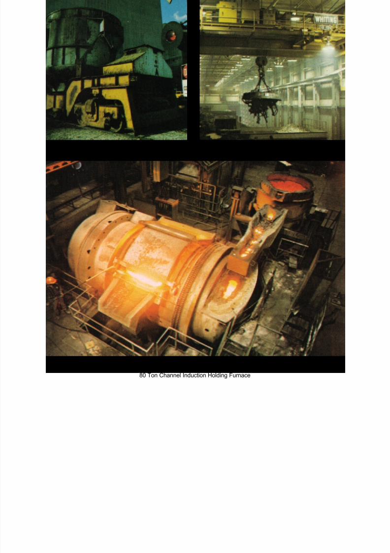
7/21/2019 Metal Shop - Foundry_handbook
http://slidepdf.com/reader/full/metal-shop-foundryhandbook 54/56
50 Cu. Ft. Clamshell Arc Furnace Charging BucketSelf-Propelled Radio Controlled Transfer/Scale Car
10 Ton Charge Make-up Crane
80 Ton Channel Induction Holding Furnace
7/21/2019 Metal Shop - Foundry_handbook
http://slidepdf.com/reader/full/metal-shop-foundryhandbook 55/56
Copyright 2004, by Whiting Equipment Canada Inc., Welland, Ontario, L3B 5P4

7/21/2019 Metal Shop - Foundry_handbook
http://slidepdf.com/reader/full/metal-shop-foundryhandbook 56/56
WHITING