metal cutting band saw - ogiri woman · controls for the optional dbw-15 buttwelder are described...
TRANSCRIPT

i
PLEASE READ THIS MANUAL CAREFULLY BEFORE OPERATING THE MACHINE!
MODEL FIRST SERIAL NO. LAST SERIAL NO.
PRINTED IN U.S.A. PB-512 (4-04)
For your information and future reference, pertinent data concerning yourmachine is stamped on a plate attached to your machine. Be sure to providemachine model and serial numbers with any correspondence or parts orders.
Specifications contained herein were in effect at the time this manual wasapproved for printing. Our policy is one of continuous improvement, reservesthe right, however, to change specifications or design at any time without noticeand without incurring obligations.
OPERATOR'S INSTRUCTION MANUALMETAL CUTTING BAND SAW
VCS-20vsd 574-04101

ii
TABLE OF CONTENTSMACHINE DIMENSIONS
Floor Plan ............................................................... 1Front View............................................................... 2
MACHINE FEATURES
Front View............................................................... 3
INSTALLATION
Location .................................................................. 4OSHA Notice........................................................... 4Cleaning .................................................................. 4Unpacking ............................................................... 4Lifting ...................................................................... 4Machine Alignment .................................................. 4Electrical Installation ............................................... 5Plant Air Installation (If Required) ............................. 5Preparation for Use ................................................. 5
OPERATION
Safety Precautions .................................................. 6Using the Blade Chart ............................................. 6Electrical Controls ................................................... 7Band Speed Controls .............................................. 7Saw Band Preparation ............................................. 7-9Post Adjustment ..................................................... 9Worktable ............................................................... 9Wheel Brush and Chip Removal .............................. 10Typical Operation Procedures .................................. 10-11
LUBRICATION
Lubrication Chart ..................................................... 12Lubrication Diagram ................................................ 13
MAINTENANCE
Replacing Crowned Bandwheel Tires ....................... 14Insert-Type Saw Guides .......................................... 14Electric Motors ........................................................ 14Head Components .................................................. 14Transmission........................................................... 14Wheel Brush ........................................................... 14Machine Cleaning.................................................... 14Band Drive Belts ..................................................... 14Variable Pulley ........................................................ 15Mist Coolant ............................................................ 15
TROUBLE SHOOTING .................................. 16-17
ACCESSORIES
Disc Cutter .............................................................. 18Rip Fence ............................................................... 18Workholding Jaws ................................................... 18Air-Operated Power Feed ........................................ 18-19Chip Blower ............................................................. 19Mist Coolant ............................................................ 19Band Mist Lubricator ............................................... 19Worklamp ............................................................... 19Post Elevating Handwheel ....................................... 20Worktable Option .................................................... 20DBW-15 Buttwelder ................................................. 20Optional Saw Guide Blocks..................................... 20-21
REPLACEMENT PARTS
Machine Specifications............................................ 22Parts Manual ........................................................... 22Index ....................................................................... 22Assembly Drawings and Parts Lists ........................ 24-82
DBW-15 BUTTWELDER
Table of Contents .................................................... 85
How to read your serial number:

1
MACHINE DIMENSIONS
FLOOR PLAN
INCHES (± .03)MILLIMETERS (± 1 mm)

2
MACHINE DIMENSIONS (Continued....)
FRONT VIEW
INCHES (± .03)MILLIMETERS (± 1 mm)
13" (330.2 mm) 80.17 (2036.3 mm)
19" (482.6 mm) 86.17" (2188.7 mm)
25" (635.0 mm) 92.17" (2341.1 mm)
31" (787.4 mm) 98.17" (2493.5 mm)
A BDimensions
WorkHeight

3
MACHINE FEATURES
FRONT VIEW

4
INSTALLATIONAll “left”, “right”, “front” and “rear” designa-tions in this manual are as viewed by theoperator facing the machine's controls.
LOCATION
1. The floor area required for the machine is approxi-mately 46 inches (1168.4 mm) in width by 44.5inches (1130.3 mm) in length. Machine heigh is 80.17inches (2036.3 mm). Refer to pages 1 and 2 for othermachine dimensions.
2. Locate the machine to provide adequate space foryour sawing needs. Be sure also to provide sufficientclearance for opening doors, loading and unloading ofstock, maintenance and lubrication procedures, plusoperation of any machine accessories.
OSHA NOTICE!!
OSHA Regulation 1910.212 (5B).Machines designed for a fixed location shallbe securely anchored to prevent walking ormoving.
UNPACKING
1. The machine is fastened to and shipped on a woodenskid. Overseas shipments are also crated.
2. Carefully remove all protective covers, strapping,hold-down brackets, crating, etc. Then: (a)Removeall bolts which fasten the machine to the shippingskid; (b)Check inside the rear drive compartment forother removable brackets, extra machine parts and/or supplies which might have been placed there forshipment. (c) Inspect the machine and all parts forshipping damage. Claim procedures are listed onthis manual’s inside front cover.
CLEANING
1. If necessary, use solvent to remove any rust-preven-tive coating applied to exposed bare metal surfacesbefore shipment.
LIFTING
1. A tapped hole is located on top of the machine's sawhead. Screw a forged 3/4-10NC eye-bolt (not sup-plied) into this hole for lifting purposes. Net weight ofthe machine is approximately 1250 pounds (567 kg).
DO NOT lift the machine by its sawing head orworktable.
MACHINE ALIGNMENT
1. To properly align the machine, place shims betweenthe floor and the base mounting pads until themachine is level with weight resting evenly on all thebase pads.
Shim Locations.
2. Lower the post and place a good quality, 10 inch (255mm) master square on the worktable against thepost's back side. Measure clearance between thepost and square near the bottom of the post. Clear-ance should be within 0.007-inch ±0.005-inch (0.18mm ±0.13 mm) at the bottom of the post.
Squaring Worktable to the Post.
3. Add or remove shims under the base pads until thecorrect post to square clearance is obtained.
The machine must be bolted to the floor forworktable loads over 100 pounds (45.4 kg).

5
ELECTRICAL INSTALLATION
Electrical installation must be made by autho-rized electrical maintenance personnel only!
1. Refer to the machine specifications plate on themachine frame to verify that the electrical supplycircuit will meet the voltage/phase/frequency/amper-age requirements listed.
2. Bring the incoming power leads into the machine'selectrical panel located inside the drive compartmentin the rear of the machine. Refer to the electricalschematic, if necessary, when making the connec-tions.
3. Turn the disconnect switch the electrical control boxenclosure to ON. Then: (a) Alternately jog the BandStart and All Stop pushbuttons; (b) Check to makesure the saw band is running in a downward motion;(c) Reverse the leads if saw band movement isincorrect.
4. The motor overload relay for the band drive motor isincluded in the function of the band drive invertercontrol.
PLANT AIR INSTALLATION (If Required)
1. Plant air (shop air) is required to operate the optionalsliding air table, chip blower and mist coolant.
2. The incoming air supply is connected at the drivecompartment wall in the rear of the machine. Airpressure must be in the range of 80 to 90 psi (5.6 to6.3 kg/cm²).
DO NOT exceed 90 psi (6.3 kg/cm²).
PREPARATION FOR USE
1. The machine will accept saw band widths from 1/16to 1/2 inch (1.5 to 12.7 mm) and 154 inches (3910mm) in length. See the "Operation" section later inthis manual for instructions on installing and remov-ing the saw band and related adjustments.
2. Make electrical connections to the machine whilereferring to the electrical schematic.
3. All covers and guards are in place, doors are closedand the operator has read the instruction manual andunderstands the safety rules and operation of themachine.
4. Make sure all points listed in the Lubrication Charthave been checked or properly serviced.

6
OPERATIONSAFETY PRECAUTIONS
Warning Label.
USING THE BLADE CHART
1. Refer to the Blade Chart escutcheon on the front ofthe machine for information about suggested bandspeed for material type and thickness.
2. Locate the material type to be cut and then move tothe right to find the recommended band speed underthe material height column.
3. If a radius cut is to be made, note the minimumrecommended blade width on the radius cutting chart.Refer to a saw blade specification table to determinethe recommended saw band gage and set.
4. For example, to cut low carbon steel which is two(2) inches (50.8 mm) thick, you would set the bandspeed to 330 feet per minute (100.6 m/min.).
Blade Chart recommendations can be ad-justed to meet special requirements.
For future reference, keep a record of bandspeeds and other application settings for suc-cessful jobs.
Blade Chart

7
ELECTRICAL CONTROLS
1. The following controls are located on the side of theelectrical control box:
• Disconnect Switch. This switch supplies incom-ing power to the machine.
• Start. Push this green button to start the band drivemotor.
• Stop. Push this red mushroom head button to stopthe band drive motor. This button latches down whenpushed and must be released or reset before themachine can be operated. To release or reset, ro-tate the button head clockwise until the head popsup.
Electrical Control Box.
2. Worklight (Optional). A switch on the worklightturns the light "off" and "on". On some machines,there is a selector switch on the electrical controlbox above the Start pushbutton that turns the light"off" and "on".
3. Controls for the optional DBW-15 Buttwelder aredescribed in a seperate section later in this manual.
BAND SPEED CONTROLS
1. The transmission gear shift lever, band speed indi-cator, and variable speed handwheel are located onthe machine's right side below the worktable.
2. The operator can select between "high" and "low"band speed ranges by moving the transmission gearshift lever: (a) To the left to obtain "high" range speeds-- 950 to 5200 fpm (292 to 1584 m/min); (b) To theright to obtain "low" range speeds -- 55 to 300 fpm(17 to 90 m/min).
• The "neutral" position is in the middle of the slot.The band speed MUST be at its lowest speed beforethe shift lever can be moved to "neutral".
3. Variable speed within both ranges is changed by turn-ing the band speed handwheel. Turn the handwheelclockwise to "decrease" the band speed, counter-clockwise to "increase" it. To determine when thedesired speed has been reached, refer to the bandspeed indicator while turning the handwheel.
4. During machine operation, keep the following bandspeed and gear shifting precautions in mind:
Adjust the band speed handwheel only whilethe machine is running.
Always turn the speed speed handwheel toits lowest speed before stopping the machineor shifting into "neutral".
Always allow the saw band to stop completelybefore opening any bandwheel door.
Stop the machine to shift gears. Then turnthe drive bandwheel by hand to engage theclutch while shifting.
5. If the transmission gears are not in position to mesh:(a) Turn the machine off; (b) Open the lowerbandwheel door, and; (c) Manually turn the lowerbandwheel until meshing occurs. DO NOT attemptto force the gear shift lever into place.
SAW BAND PREPARATION
Saw Band Selection
1. The machine is equipped with an Imperial Bi-MetalSuper Silencer saw band that is 154 inches (3910mm) long. It will accept saw band widths from 1/16to one (1) inch (1.5 to 25.4 mm).
2. Standard equipment includes:
• One (1) set of high-speed, insert-type saw guideblocks for saw bands from 1/16 to 1/2 inch (1.5 to12.5 mm) wide.
• One (1) set of steel saw guide inserts for saw bands1/4 to 1/2 inch (6.4 to 12.5 mm) wide.

8
Insert-Type Saw Guide Adjustment
These instructions apply to both the upper andlower insert-type saw guide blocks.
1. Select the saw guide blocks and inserts marked forthe width of the saw band to be used. Then: (a)Place the right insert in the right milled slot; (b)Tighten the insert screw slightly so that the insertwill slide in the slot, yet still hold its correct positionwhen released.
Positioning the Right Insert.
2. Select the insert gage which matches the size ofthe saw band being used. Then: (a) Place the in-sert gage in the left slot; (b) Adjust the right insert tofit exactly into the notched end of the gage; (c) Tightenthe right insert screw.
3. Place the left insert in its slot and tighten the insertlightly. Then: (a) Place the gage edgewise betweenboth inserts; (b) Lower the left insert until it restsagainst the gage; (c) Tighten the left insert screw.
Positioning the Left Insert.
Insert-type saw guides are recommended formaximum band speeds of 1300 fpm (390 m/min) for production sawing, or up to 5000 fpm(1500 m/min) for occasional sawing. Use op-tional roller saw guides for continuous saw-ing over 1300 fpm (390 m/min).
SAW BAND PREPARATION (Continued....) Saw Band Removal
Always use extreme care when handling sawbands.
1. Release saw band tension. Then: (a) Open bothbandwheel doors; (b) Remove the post saw bandguard; (c) Loosen the screw holding the worktable'ssawing slot clamp bar and move it aside.
2. Carefully slip the worn or broken saw band from theslot in the column guard, the saw guide inserts andthen remove it from around both bandwheels.
Saw Band Installation
Always use extreme care when handling sawbands.
1. Remove the old saw band according to the direc-tions above. Then: (a) Place the new saw bandcarefully through the slot in the column guard, aroundthe bandwheels and between the upper and lowersaw guide inserts; (b) The center of the saw bandshould track along the center of the bandwheel tires.
2. Remove the new saw band's protective Saw Cap.Then: (a) Apply the band tension recommended bythe scale adjacent to the tension adjustment knob;(b) Reinstall the post saw band guard; (c) Reposi-tion and secure the worktable sawing slot clamp bar.
Saw Band Tension Adjustment
1. Saw band tension is adjusted by turning the knoblocated below the machine's sawing head (this knobalso is used to lock the post in place).
2. A scale showing the recommended tension for vari-ous saw band widths is located to the right of thetension adjustment knob. Scale numbers representthe recommended tensions for common saw bandgages and pitches.
Adjusting Saw Band Tension.

9
3. The following are operator tensioning recommenda-tions:
• Reduce the recommended band tension when us-ing saw bands with a coarser pitch or lighter gage.
• Increase the recommended band tension when us-ing heavier gage saw bands.
Saw Band Tracking
1. The upper bandwheel can be tilted a maximum ofthree (3) inches (76.2 mm) forward and backward tohelp obtain correct saw band tracking. A saw bandis tracking properly when the saw band center fol-lows the center of both crowned rubber bandwheeltires.
2. The following tracking procedures are to be performedwith the band drive motor off and the transmission in"neutral": (a) Open both bandwheel doors; (b) Manu-ally turn the bandwheels to observe how the sawband is tracking.
Tilt Adjustment Handles.
3. To adjust bandwheel tilt if tracking is not correct: (a)Loosen the tilt lock handle; (b) Turn the tilt adjust-ment handle until the saw band tracks correctly onthe bandwheel tires; (c) Retighten the tilt lock handle.
4. Close both bandwheel doors.
POST ADJUSTMENT
1. Post and upper saw guide elevation can be adjustedto accept workpieces with heights varying up to 13inches (330.2 mm).
2. To adjust: (a) Loosen the lockscrew located insidethe upper bandwheel door by using the adjustmentknob and turn counterclockwise (this knob alsoused for band tension adjustment); (b) Raise or lowerthe post manually to the desired position; (c) Turnthe adjustment knob clockwise to lock the post inposition.
Post Adjustment.
3. Some machines have a optional post elevatinghandwheel which uses a set of gears to raise andlower the post. Refer to the "Accessories" sectionfor use of this option.
WORKTABLE
1. The standard worktable measures 26 by 26 inches(660.4 by 660.4 mm). Its load capacity is approxi-mately 150 pounds (68.0 kg) evenly distributedwith NO impact.
The machine must be bolted to the floor fortable loads over 100 pounds (45.4 kg).
2. The worktable has drilled holes on the front and rightsides to attach accessory equipment.
3. There is several worktable options to choose from tomaximize your machine's productivity. Refer to the"Accessories" section for description and use of thevarious worktable options.
SAW BAND PREPARATION (Continued....)

10
WHEEL BRUSH AND CHIP REMOVAL
1. A brush, located on the lower bandwheel approxi-mately in the ten (10) o'clock position, cleans metalchips from the bandwheel during machine operation.Removed chips drop into a removable pan in themachine base. This pan should be emptied periodi-cally.
DO NOT open the bandwheel doors until sawband has completely stopped.
2. During operation, chips and other depris may accu-mulate around such machine areas as saw guides,worktable surfaces, bandwheels, slides, etc. Re-move this debris as soon as possible. It is recom-mended that you remove chip collections atleast twice per each eight (8) hour shift, andmore often with heavier use.
TYPICAL SAWING PROCEDURES
These procedures assume that the following machine condi-tions exist: (a) The machine has been properly installed andaligned; (b) The band drive motor is off; (c) The proper sawband has been installed, is correctly tracked and tensioned;(d) All lubrication procedures have been carried out.
1. Raise the post high enough so that the upper sawguide can not be damaged while stock is being loadedonto the worktable.
2. If necessary, tilt the optional worktable to the de-sired angle and lock it in place.
3. Load stock to be cut onto the worktable. Clamp thestock if necessary.
4. Lower the post until the upper saw guide is just abovethe stock, but NOT touching.
5. Determine the band speed range and desired bandspeed for the procedure to be undertaken. Then:(a) Use the transmission gear shift lever to choosebetween "high" and "low" band speed ranges; (b)Push the Start button; (c) Turn the band speedhandwheel to the band speed desired.
6. Carefully move the stock toward the saw band andbegin the cut. Adjust the band speed as necessaryduring the cutting procedure.
7. After the cut has been finished: (a) Turn the bandspeed handwheel to its lowest speed; (b) Push theStop button; (c) Remove the piece just cut from theworktable; (d) Reposition the stock to begin anothercut; (e) Push the Start button and then set the bandspeed.
Contour Sawing
1. Procedures for stock set-up and band speed adjust-ment are the same as noted for production sawingexcept that contour sawing of large, heavy stock willrequire the use of optional air-operated power feed orair-powered worktable and a heavy gage saw band.
2. The following are important contour sawing precau-tions which should be observed:
Reduce the feed force when cutting into anopening to prevent saw band damage.
DO NOT feed work so rapidly that saw bandtwisting or bowing occurs.
For future reference, keep a record of bandspeed, feed pressure and coolant applicationsettings for successful jobs.
3. A hole is usually drilled in the stockpiece when asharp corner is to be cut, as shown in the illustra-tion. However, a corner may also be by-passed bycutting a curve, and leaving the remainder to benotched out later.
Starting Hole for Sharp Contour Cutting.
Internal Contours
1. To prepare for internal contour sawing: (a) Drill astarting hole in the stock; (b) Run the saw bandthrough the hole; (c) Weld the saw band. Insulatethe saw band from contact with the stock or theworktable will insure a better weld.
2. The diameter of the drilled starting hole is determinedby the size of the saw band being used. Use thewidest possible saw band for cutting the curve.

11
Internal Contour Sawing.
3. Attempting to cut too small a radius with too wide asaw band will cause binding, and the lower bandwheelmay become grooved. The Blade Chart shows mini-mum radii cuts possible with various saw band widths.
4. Radii chart recommendations are based on sawingrelatively thin stock. Consider these variations: (a)Use a heavy gage saw band for heavy stock sawing;(b) Use a narrower than recommended saw bandwhen sawing stock more than one (1) inch (25.4 mm)thick.
TYPICAL SAWING PROCEDURES Continued....)

12
LUBRICATIONLUBRICATION CHART
LOCATION DESCRIPTION ANDSERVICE RECOMMENDATIONS
RECOMMENDEDLUBRICANT
LUBRICATIONINTERVAL*
LUBRICATIONPOINT NO.
Variable Pulley. One (1) oil cup.1 WEEKLY
Band Tension Screw and Bearing. Clean and apply oil.2
3
MONTHLY
5
6
Table Trunnion (Optional). Oil tilt surfaces. MONTHLY
7
8
Post. Clean and apply oil. MONTHLY
Upper Bandwheel Slide, Hinge, and Tilt Screw.Clean and apply oil.4 MONTHLY
CHECKMONTHLY
Accessory Equipment as Supplied. Keep clean andapply oil as required to to maintain proper function, reducewear, and corrosion, etc.
CHECKMONTHLY
High quality, rust and oxidation-inhibited,medium hydraulic and general purposeindustrial oil.
ISO-VG Grade 68 (Formerly ASTM GradeNo. 315).
Union 76, UNAX RX 68, or equivalent.
High quality, EP (extreme pressure) multi-purpose gear oil.
S.A.E. Grade No. 90.
Union 76, MP Gear Lube 90 or equivalent.
9Transmission. One (1) quart (0.95 liter) capacity. Properoil level must be maintained. Drain and refill yearly orwhen required
CHECKMONTHLY
Electric Motor. Oil cup and/or grease fittings.10 Lubricate (if any) per manufacturer's recommendations.
11 Mist Coolant Reservoir (Optional). Keep filled andhoses clear.
DBW-15 Buttwelder (Optional). Lubricate as required per DBW-15 Instruction Manual.12* Lubrication intervals are based on a 8-hour day, 40-hour week. Lubricate more often with heavier use.
Speed Change Screw and Linkage. Clean and apply oilas required.
CHECKMONTHLY
Miscellaneous: Slides, Hinges, Pivot Points, Compo-nent Parts, Unpainted Surfaces, etc. Clean and applyoil as required.
Premium quality, saw band coolant andlubricant.
CHECK DAILY/AS REQUIRED

13
LUBRICATION DIAGRAMS
FRONT VIEW
REAR VIEW

14
MAINTENANCEREPLACING CROWNED BANDWHEEL TIRES
1. Loosen the worn tire with a screwdriver or other flattool.
2. Stretch the tire if necessary to remove it.
3. Clean the bandwheel and install a new tire by stretch-ing it over the bandwheel.
INSERT-TYPE SAW GUIDES
Roller Back-Up Bearing
1. These bearings are sealed and packed for life with aspecial lubricant. They can be replaced by: (a)Removing the snap ring; (b) Pulling out the bearingand shaft; (c) New bearings are easily installed witha light press fit.
ELECTRIC MOTORS
1. Follow the manufacturer's maintenance instructionsfor each electric motor.
HEAD COMPONENTS
1. Wipe oil onto the post occasionally. Then move thepost up and down through the slide block severaltimes.
2. Oil the upper bandwheel slide and band tension screweach month.
3. Wheel bearings are sealed and lubricated for life.
TRANSMISSION
1. Drain, flush, and refill the transmission yearly. Fill tothe bottom of the check plug opening with oil recom-mended by the Lubrication Chart.
Checking Oil Level.
2. Check often for seal leaks around the shaft.
3. Immediately investigate any loud or unusual noises,or rough operating vibration.
4. Return a faulty transmission to the factory for repair.
Correct new transmission installation is ex-tremely important because careful alignmentis necessary. Installation by a factory servicerepresentative is highly recommended.
WHEEL BRUSH
1. Check the lower bandwheel brush occasionally forcorrect position. Adjust the brush so it just touchesthe bandwheel tire.
Too much pressure of the brush will score thebandwheel tire.
2. Replace the brush when necessary.
MACHINE CLEANING
Stop the machine when cleaning the machineor opening bandwheel doors or covers.
1. Keep the machine and its parts as clean as pos-sible to prevent excessive wear and damage.
2. Remove the chip pan and dispose of the chips whennecessary.
3. Metal chips and other waste materials may collectaround areas such as: saw guides, table surface, T-slots, bandwheels, slides, etc. Remove these ma-terials as soon as possible. It is recommendedthat you remove chip collections at least twiceper each eight (8) hour shift, and more oftenwith heavier use.
BAND DRIVE BELTS
1. Belts driving the variable pulley and input sheave willstretch during use. This stretch is taken up auto-matically by the counter-balancing weight of the drivemotor on its mounting plate.
2. To replace the belts: (a) Lift the drive motor andblock it in place; (b) Slip the old belts from theirpulleys and install the new ones; (c) Remove theblock from the drive motor.

15
VARIABLE PULLEY
1. Remove, wash and clean the variable speed pulleywith solvent every six (6) months. Then: (a) Checkto see that the pulley's center sheave is free to shiftsideways; (b) Check the pulley for scoring whichcould damage the belts.
2. Bearings are lubricated from an oil cup in the shaftend.
DO NOT over-lubricate. This will cause oil tocoat the belts and pulley and will cause slip-page.
MIST COOLANT
1. Intermittent coolant stream indicates an air leak.Check all joints.
2. Clogging may occur if waxed-based or other cool-ants are used. Your service representative can pro-vide complete information about various coolants.
3. Keep the mist applicator nozzle and filter clean. Ifthe center nylon coolant tube needs replacing, re-move the entire applicator tube. Insert new nylontube and trim off excess flush with nozzle. Makesure all joints are sealed and tight after applicatortube is reinstalled.

16
TROUBLE SHOOTINGRepair and adjustment procedures should bemade by experienced maintenance person-nel, or by a factory service representative. Ref-erence to the machine's electrical schematicwill be helpful.
MACHINE WON'T START
1. Make sure the disconnect switch is in the "on" posi-tion.
2. Make sure the bandwheel doors are closed.
3. Check the main fuses and control circuit fuses forfaulty operation.
4. Check the transformer for faulty operation.
MACHINE VIBRATION
1. Check for unbalanced bandwheels.
2. Check for worn or unbalanced band drive belts.
3. Check for an incorrectly shimmed machine base.
SAW BAND VIBRATION
1. Incorrect band speed or feed force is being used.
2. Choice of blade pitch is incorrect.
3. Stock is not being clamped firmly to the worktableand/or optional vise jaws.
4. Check for worn or improperly adjusted saw guideinserts.
5. Check for a worn saw guide back-up bearing.
6. Check for a loose post. Adjust the two (2) springplungers if necessary.
7. Check for a poor weld in the saw band.
8. Check for an incorrect saw band tension setting.
SAW BAND IS CUTTING INACCURATELY
1. Check for worn blade teeth. Inserts that are too widefor the blade will damage the teeth set.
2. Check for scale on the stock.
3. The saw band may be too wide if a radius is beingcut.
4. Check for incorrect saw band, post or insert align-ment.
5. Incorrect band speed or feed force is being used.
6. Coolant (if supplied) is not being applied evenly toboth sides of the saw band.
7. Check for an incorrect saw band tension setting.
8. The upper saw guide is not located close enough tothe stock.
9. Check for worn or loosely-adjusted saw guide inserts.
EXCESSIVE INSERT AND BLADE WEAR
1. Inserts or roller saw guide are adjusted too tightly onthe saw band.
2. High band speed is causing friction (using roller sawguides may be adviseable). Increase coolant (if sup-plied) volume to better lubricate the saw band.
3. The back-up bearing may need replacement.
4. Check for incorrect saw band tension setting.
PREMATURE BLADE TEETH DULLING
1. The saw band is not being "broken" in on the firstfew cuts. Reduce the feeding pressure when mak-ing these cuts.
2. Band speed is too high (this causes abrasion).
3. Saw band pitch is too coarse.
4. Coolant (if supplied) is not properly covering the sawband.
5. The cutting rate is too high.
6. Check for faulty material such as heavy scale, inclu-sions, hard spots, etc.
7. Check for saw band vibration.
8. Check for chip welding, or for a chipped tooth lodgedin the cut.

17
TROUBLE SHOOTING (Continued....)
9. Check for incorrect saw band tension setting.
10. Inserts are incorrect for the width of blade being used.This allows the inserts to hit the set teeth (listen forclicking sounds during saw band operation).
SAW BAND SLIPS OFF BANDWHEEL
1. The upper bandwheel is not aligned properly. Thesaw band needs to be tracked.
2. Check for slippery coolant, or excessive coolant vol-ume (if supplied).
3. Check for incorrect machine alignment.
4. Check for a worn or improperly-adjusted wheel brush(this allows chips to remain on the bandwheel tire).
5. Incorrect saw guides are being used.
6. Check for incorrect saw band tension setting.
SURFACE FINISH ON WORK IS TOO ROUGH
1. Check for a worn saw guide insert (adjust or replaceif necessary.
2. Band speed is too low or feed force is too heavy.
3. Blade pitch is too coarse.
4. Check for saw band vibration.
5. Check for a poor weld in the saw band.
NO COOLANT FLOW (If Supplied)
1. Make sure reservoir is full.
2. Check for a clogged coolant applicator nozzle.
3. Check for a clogged or kinked coolant hose.
4. Check for a clogged or damaged coolant control valve.
TRANSMISSION WILL NOT STAY IN GEAR
1. Check for worn gears.
Transmission replacement, repairs, adjust-ments or alignment should be performed onlyby a factory service representative.
TRANSMISSION WILL NOT SHIFT INTO GEAR
1. Check the shift linkage for loose set screws or bro-ken spring pins.
2. Check for a jammed shift mechanism.
3. Check for jammed or damaged sliding clutch jaws.

18
ACCESSORIESThe following are accessories sometimes usedduring sawing operations. A factory repre-sentative will be happy to advise you aboutthe current availability of any accessory.
DISC CUTTER
1. This attachment can be used to cut internal or exter-nal circles from 2-1/2 to 30 inches (63.5 to 762.0mm) in diameter. To set up the disc cutter:
• Place flat washers under the mounting screws. Then:(a) Bolt the mounting bracket to the post; (b) Lowerthe post until the upper saw guide is approximately3/8 inch (10 mm) above the worktable; (c) Loosenthe fine adjustment and arm clamp bolts; (d) Movethe center pin to the approximate distance of theradius to be cut; (e) Tighten the fine adjustment clampbolt.
Disc Cutter.
• Position the center pin so that it is perpendicular tothe saw band's cutting edge. To do so: (a) Place asquare against the tip of a sawband tooth; (b) Loosenthe vertical adjustment clamp bolt; (c) Line up thecenter pin with the square's blade edge; (d) Clampthe vertical adjustment clamp bolt.
• Make final radius adjustments with the fine adjust-ment wheel. Then: (a) tighten the arm and radiusarm clamp bolts while making sure the center pin issquare to the table; (b) Adjust the disc cutter forstock thickness by raising or lowering the post.
RIP FENCE
1. Square this fixture during installation so that it is inline with the worktable sawing slot. When align-ment is correct, secure the adjusting screws in placewith the set screws under the the guide bar on therip fence casting.
2. Before attempting a long cut, check to see that thesaw band is not worn on one side. This will causestock to wander relative to the rip fence guide bar.
Rip Fence.
WORKHOLDING JAWS
1. This option is used for off-hand and contour sawing.By looping a power feed chain around the workholdingjaws, the operator can use the cable pulley systemto guide stock along the contour layout lines.
Be sure to use the correct saw band widthwhen cutting a radius.
Workholding Jaws.
AIR-OPERATED POWER FEED
This option requires shop air: 20 psi (1.4 kg/cm²) minimum; 100 psi (7.0 kg/cm²) maximum.It has been tested at 70 psi (4.9 kg/cm²) pres-sure during factory inspection.
1. Air power feed provides steady feeding pressure andallows the operator to use both hands to guide thestockpiece.

19
2. This system has: (a) A pressure-regulating valveand gauge located slightly below the left worktablesurface; (b) A pulley and cable system attached byan adjustable bracket to the rear worktable edge andto an air cylinder mounted to the machine base.
3. Operation procedures are as follows:
• Adjust the pulley and cable system for stock width.This is done by: (a) Loosening the two (2) knobslocated under the rear mounting bracket; (b) Remov-ing any slack in the workholding chain.
Chain and Pulley System.
• Set the desired feed force with the regulating valveknob. Turn the knob clockwise to increase feedforce, counterclockwise to decrease it. Refer tothe gauge for pressure readings.
Pressure Valve and Gauge.
• Place stock between the workholding jaws and re-move any slack in the cable. Next: (a) Start themachine; (b) Begin the cut by pushing down slightlyon the foot pedal.
• Feed force can be increased while sawing by apply-ing additional pressure on the foot pedal. When thesawing is finished, remove your foot from the pedalto relax feed force.
A special oil-mist lubricator is included withthis option.
CHIP BLOWER
1. The operator can remove chips from the sawing areaby using the chip blower. Shop air is used to deliverair to the cutting area.
2. Adjust the flexible hose and nozzle to direct chipsaway from the sawing area.
3. The air supply connection is located on the left sideof the machine on the drive compartment wall. In-coming air supply should be between 80 and 90 psi(5.6 and 6.3 kg/cm²).
DO NOT exceed 90 psi (6.3 kg/cm²).
MIST COOLANT
1. Using shop air, this option has a valve with sightglass and a one (1) quart (0.95 liter) supply bottlemounted on the rear side of the head.
2. Air and coolant are mixed in a manifold to form a finemist. Adjust the flexible tube to direct mist streamonto saw band and workpiece to lubricate and coolthe cutting area. Regulate mist with adjustable valveat a rate of one drop per second as seen through thesight glass.
3. The air supply connection is located on the left sideof the machine on the drive compartment wall. In-coming air supply should be between 80 and 90 psi(5.6 and 6.3 kg/cm²).
DO NOT exceed 90 psi (6.3 kg/cm²).
4. Your service representative can provide complete in-formation on various coolants.
BAND MIST LUBRICATOR
1. See the instructions sent with the unit for informationon operation and adjustments.
WORKLAMP
1. The worklight illuminates the cutting area and areasnearby and is controlled by an "on/off" switch on thelamp, or by selector switch on the electrical controlbox.
AIR-OPERATED POWER FEED (Continued....)

20
POST ELEVATING HANDWHEEL
1. This option allows the operator to adjust the postand upper saw guide by means of a handwheel lo-cated on the right side of the sawing head. Turn thehandwheel clockwise to "raise" the post, counter-clockwise to "lower" it.
WORKTABLE OPTION
26" Tiltable Worktable
1. These factory installed worktables measures 26 by26 inches (660.4 by 660.4 mm) and replaces thestandard fixed worktable. Load capacity is 500pounds (226.8 kg) evenly distibuted with NOimpact for either table.
The machine must be bolted to the floor fortable loads over 100 pounds (45.4 kg).
Tiltable Worktable.
2. The worktable can be tilted manually up to 10º leftand 45º right -- primarily for sawing compound angles.The amount of worktable tilt is indicated by a pointerand a trunnion-mounted calibrated scale.
3. To tilt the worktable: (a) Use the wrench provided toreach through the machine frame and under the work-table to loosen the tilt locknut; (b) Tilt the worktablemanually until the pointer reaches desired angleshown on the scale; (c) Tighten the tilt locknut.
DBW-15 BUTTWELDER
1. Information covering blade welding, plus operationand maintenance of the optional DBW-15 Buttwelder(with flash grinder and blade shear) are provided in aseperate section later in this instruction manual.
OPTIONAL SAW GUIDE BLOCKS
1. It is possible to equip the machine with precision,heavy-duty, high speed, insert-type saw guides orroller saw guides.
Insert-Type Saw Guides
• High speed, heavy-duty saw guide blocks are forband speeds up to 6000 fpm (1830 m/min).
High Speed Saw Guides (Standard)
• Precision saw guide blocks are used for band speedsup to 2000 fpm (608 m/min) with saw band widths of1/16 to 1/4 inch (1.5 to 6.4 mm).
Precision Saw Guides.
• Saw guides with steel or carbide-faced back-up bear-ings with saw band widths of 1/16 to one (1) inch(1.5 to 25.4 mm) can be used with this machine.
Heavy-Duty Saw Guides With Steel or Carbide-Faced Back-Up Bearing.

21
Roller Saw Guides
1. Use roller saw guides for continuous high-speed saw-ing. They are recommended for continuous sawingat band speeds over 1300 fpm (390 m/min).
• Type I roller saw guide blocks use 1/4 to 1/2 inch(6.4 to 12.7 mm) saw bands and are for band speedsup to 6000 fpm (1830 m/min).
Type I Roller Saw Guides.
• Type II roller saw guide blocks use 1/4 to one (1)inch (6.4 to 25.4 mm) saw bands and are for bandspeeds up to 6000 fpm (1830 m/min).
Type II roller saw guide blocks reduce thework height capacity by one (1) inch (25.4 mm)and restricts right table tilt to 27°.
Type II Roller Saw Guides.
2. Roller saw guides are adjusted as follows:
• Select the rollers which match the width of saw bandto be used. Next: (a) Place one (1) back-up roller(has a rear flange) and one (1) side roller in upperguide block; (b) Place one (1) back-up roller and one(1) side roller in the lower saw guide block in oppo-site position of the upper guide; (c) Attach the upperroller guide to the post and the lower roller guide tothe keeper block.
• Place the saw band over the upper and lowerbandwheels. Next: (a) Adjust the saw band ten-sion; (b) Loosen the roller lock screw; (c) Bring therollers toward the saw band by turning the eccentricbearing shaft with a screwdriver. The rollers shouldbe just free enough to turn without moving the sawband.
The bearings will overheat if the rollers aretoo tight against the saw band. Conversely,rollers that are too loose may cause the sawband to wobble and affect cutting accuracy.
• Tighten the roller lock screws to prevent the eccen-tric shaft from turning and changing the roller adjust-ment.
OPTIONAL SAW GUIDE BLOCKS (Continued....)

22
REPLACEMENT PARTSINDEX
Final AssemblyAir Feed Assembly*Auxiliary Post Support Assembly* (Extra Work Height)Band Lubricator Assembly*Bandwheel AssembliesCarrier and Cable Sub-Assembly (Air Feed)Chip Blower Assembly* (And Related Items)Disc Cutter Assembly*Drive AssemblyElectrical AssemblyElectrical Control Box AssemblyExtra Work Height Assembly*Guard Assembly* (Point of Operation)Head AssemblyMist Coolant Assembly* (And Related Items)Motor Base AssemblyPost AssemblyPost Elevating Handwheel Assembly*Rip Fence Assembly*Saw Guide Assemblies (Standard)Saw Guide Assemblies (Insert Type)Saw Guide Assemblies (Roller Type)Table and Trunnion Assembly* (Tiltable)Table Assembly (Fixed)Transmission AssemblyVariable Assembly (Speedmaster)Variable Linkage Sub-AssemblyWork Holding Jaw Assembly*
Electrical SchematicAir System Schematic*
Other Assemblies and Documents:
Air Feed Sub-Assembly* (See Air Feed)Band Tension Screw Sub-Assembly (See Head)Door Latches (See Final)Pushbutton Box Detail (See Electrical Control Box)Saw Guide Inserts and Gages (See Saw Guide)Wheel Hinge Sub-Assembly (See Head)
BUTTWELDER*
Buttwelder Table of Contents .................................. 85
* Denotes Attachment or Optional Equipment.
MACHINE SPECIFICATIONS
1. For your information and future reference, pertinentdata concerning your machine should be written inthe spaces provided above. This information isstamped on a plate attached to the rear side of yourmachine. Be sure to provide machine model andserial number with any correspondence or parts or-ders.
PARTS MANUAL
1. The following section contains the machine assem-bly drawings and corresponding parts list. The as-sembly drawing is on the left with its parts list on thefacing page. Please order carefully!
2. Be sure to provide machine model and serial num-ber with any correspondence or parts orders.
3. Lesser quality parts may lead to personal injury and/or machine damage. Original factory parts are highlyrecommended.
4. After the first page (Final Assembly), the other as-semblies follow in alphabetical order with the sche-matics at the end. See the following index of draw-ings and parts list to help locate what you are look-ing for.
MODEL SERIAL NO.
PHASECYCLEVOLTAGE
ELECTRICALSCHEMATIC
YEAR OFMANUFACTURE

��������������� � ��
�������
�� ��� ��� �������������
����������������������������� ����� ��� �����
�����������
�
�
!
�
�
"
�
�
�� �� �� �� ��
��
��
�#
��
��
��
�!
��
���"��
��
�#
!�
!�
!� !�
!"!�!#��
!� !!
�"

CODE NO. HC-1-71______________________
FINAL ASSEMBLY
INDEX PART DESCRIPTION UNITS PERNO. NO. ASS'Y.Ref. 290218H Final Assembly1 404522H . Chip Box Weldment .......................................................................................... 12 513012 . Drive Assembly (See Detail) ............................................................................. 13* 220211H . Frame Weldment .............................................................................................. 14 009400 . Knob Assembly ................................................................................................. 15 . DBW-15 Buttwelder Assembly (Optional) (See Welder Manual) ...................... 16 404476 . Escutcheon (Warning) ...................................................................................... 17 145882 . Escutcheon (Caution) (English) ........................................................................ 1
149667 . Escutcheon (Caution) (International) ................................................................ 18 . Electrical Assembly (See Detail) ....................................................................... 110 201469 . Decal (American Flag) ...................................................................................... 111 520279 . Head Assembly (See Detail) ............................................................................. 112 420710 . Blade Chart ....................................................................................................... 114 172762 . Latch ................................................................................................................. 115 198853 . Screw, Rd. Hd. Mach. #8-32NC x 3/8 ............................................................... 216 216862 . Plastic Cover ..................................................................................................... 117 131033 . Escutcheon (Warning) (English) ....................................................................... 1
131408 . Escutcheon (Warning) (International) ............................................................... 118 028081 . Upper Saw Guide Assembly (See Detail) ......................................................... 119 018500 . Upper Saw Guide Holding Screw ...................................................................... 220* 171508 . Saw Band (Imperial Bi-Metal Super Silencer) ................................................... 121 304525 . Saw Band Tag ................................................................................................... 122 420758 . Table Assembly (Fixed) (See Detail) ................................................................. 123 028082 . Lower Saw Guide Assembly (See Detail) ......................................................... 124 198246 . Screw, Soc. Hd. Cap 1/4-20NC x 1-3/4 ............................................................ 225 413965H . Guard Weldment (Standard) ............................................................................. 1
414435H . Guard Weldment (Rip Fence Option) ............................................................... 1417086H . Guard Assembly (Point of Operation) (Optional) (See Detail) ........................... 1
26 198867 . Screw, Rd. Hd. Mach. #10-24NC x 3/8 ............................................................. 227 199111 . Nut, Hex. #10-24NC .......................................................................................... 228 199320 . Washer, Lock #10 Std. ...................................................................................... 229 172654 . Escutcheon (Caution) (English) ........................................................................ 1
172655 . Escutcheon (Caution) (International) ................................................................ 130 172762 . Latch ................................................................................................................. 131 198853 . Screw, Rd. Hd. Mach. #8-32NC x 3/8 ............................................................... 232 101158 . Escutcheon (International Only) ........................................................................ 133 199397 . Screw, Rd. Hd. Drive #2 x 1/4 ........................................................................... 334 420945H . Rear Drive Cover .............................................................................................. 135 199299 . Screw, Hex. Hd. Self-Drill M4.8 x 13 ................................................................. 736 420925H . Top Drive Cover ................................................................................................ 137 199299 . Screw, Hex. Hd. Self-Drill M4.8 x 13 ................................................................. 639 100666 . Escutcheon (CSA Modification) ........................................................................ 140 . Escutcheon (Machine Specifications) ............................................................... 1
*NOTE: See Extra Work Height Assembly If Applicable.
Following Not Shown:406871 . Instruction Tag .................................................................................................. 1170091 . Box of Extra Parts ............................................................................................. 1004141 . . Saw Guide Insert Pack (See Detail) ............................................................... 1010853 . . Wrench (Table Tilt) ......................................................................................... 1199568 . . Hex. Key 3/16" ................................................................................................ 1
. Operation and Maintenance Manual ................................................................. 1206668* . Worklamp (Optional) ........................................................................................ 1417045 . Pallet ................................................................................................................ 1123001 . Shipping Bracket and Hardware (Export Only) ................................................ 1

�� �#� �!� �������������
�������������������������������������������� � �� �"� �!���
� ����� ��� �����
��������������
���������$� �����
�
�
! � � " �
�
#
��
�
�
!
� �
"
�
�
# �� ��
��
�!
����
�"
��
��
�#
��
��
��
�!
�����"����
�#
!�
�������������# �� #�
�������
������ �� ��

CODE NO. HC-9-32______________________
AIR FEED ASSEMBLY
INDEX PART DESCRIPTION UNITS PERNO. NO. ASS'Y.Ref. 513087 Air Feed Assembly1 416813 . Air Feed Sub-Assembly (See Detail) ..................................................... 12 198008 . Screw, Hex. Hd. Cap 1/4-20NC x 3/4 .................................................... 23 199321 . Washer, Lock 1/4 Std. ............................................................................ 24 203604 . Pipe Plug (Brass) ................................................................................... 15 198044 . Screw, Hex. Hd. Cap 3/8-16NC x 3/4 .................................................... 36 199332 . Washer, Lock 3/8 Std. ............................................................................ 37 34-005414 . Spacer Washer ...................................................................................... 38 420866 . Carrier and Cable Assembly (Air Feed) (See Detail) ............................. 19 115652 . Tubing Clamp ......................................................................................... 110 199484 . Screw, Pan Hd. Self-Tap 1/4-20NC x 1/2 ............................................. 111 5-027506 . 90° Street Elbow (Brass) ........................................................................ 312 002004 . Barbed Insert .......................................................................................... 313 35-006888 . Hose Clamp ........................................................................................... 614 198896 . Screw, Rd. Hd. Mach. 1/4-20NC x 5/8 .................................................. 215 199374 . Washer, Lock 1/4 Shakeproof Ext. ........................................................ 216 199115 . Nut, Hex. 1/4-20NC ................................................................................ 217 145883 . Oil-Fog Lubricator (Includes Bracket) .................................................... 118 138445 . Oil (ASTM 315) ...................................................................................... A.R.19 197094 . Neoprene Hose 11/16 O.D. (Black) ....................................................... A.R.20 172794 . Air Cylinder ............................................................................................. 121 169631 . Air Filter .................................................................................................. 122 198006 . Screw, Hex. Hd. Cap 1/4-20NC x 1/2 .................................................... 423 199321 . Washer, Lock 1/4 Std. ............................................................................ 424 199147 . Nut, Hex. Jam 1-14NF ........................................................................... 125 325663 . Cylinder Mounting Bracket ..................................................................... 126 115652 . Tubing Clamp ......................................................................................... 227 199484 . Screw, Pan Hd. Self-Tap 1/4-20NC x 1/2 .............................................. 128 172793 . Foot Valve .............................................................................................. 129 172792 . Guard ..................................................................................................... 130 128179 . Barbed Insert .......................................................................................... 2
Following Not Shown:5-013007 . Work Holding Jaw Assembly (See Detail) ............................................. 1
Ref. 416813 . Air Feed Sub-Assembly1 203219 . . Reducer Bushing (Brass) ..................................................................... 12 5-027506 . . 90° Street Elbow (Brass) ...................................................................... 13 128179 . . Barbed Insert ........................................................................................ 14 315365 . . Bracket ................................................................................................. 15 125674 . . Regulating Valve .................................................................................. 16 35-009530 . . Gauge .................................................................................................. 17 203219 . . Reducer Bushing (Brass) ..................................................................... 18 203483 . . Pipe Coupling (Brass) .......................................................................... 19 203482 . . Pipe Nipple (4") (Brass) ........................................................................ 110 008254 . . 90° Street Elbow (Brass) ...................................................................... 2

�������������� �� ��
�������
�� ��� ���� �������������
����������������������������� �� �"� �����
� ����� ��� �����
�$%����� �&���$&&��������� '�%�������(�������)
��
��
�"
�#
��
��
�!
�
"
�
��
�
#����
�
�
!
�

CODE NO. HC-2-118______________________
AUXILIARY POST SUPPORT ASSEMBLY(Extra Work Height)
INDEX PART DESCRIPTION UNITS PERNO. NO. ASS'Y.Ref. 506149H Auxiliary Post Support Assembly1 13-001423 . Post Collar .......................................................................................... 12 198048 . Screw, Hex. Hd. Cap 3/8-16NC x 1-1/2 .......................................... 23 199332 . Washer, Lock 3/8 Std. ....................................................................... 24 032463H . Upper Post Guide .............................................................................. 15 198048 . Screw, Hex. Hd. Cap 3/8-16NC x 1-1/2 .......................................... 26 199325 . Washer, Lock 3/8 Std. ....................................................................... 27 198439 . Screw, Soc. Set 5/16-18NC x 3/4 ..................................................... 48 13-001309 . Back-Up Pad ..................................................................................... 19 13-001419 . Back-Up Pad Screw 1/2-13NC x 4-1/8 ............................................ 110 199132 . Nut, Hex. Jam 1/2-13NC ................................................................... 111 35-009616 . Retaining Ring ................................................................................... 112 203551 . Escutcheon (Remove Bracket) ....................................................... 113 024337H . Support Arm ....................................................................................... 114 198067 . Screw, Hex. Hd. Cap 1/2-13NC x 1-1/2 .......................................... 115 007629 . Starwheel Assembly .......................................................................... 1
6-001103 . . Starwheel ......................................................................................... 1004261 . . Spring Pin ......................................................................................... 113-001422 . . Post Clamp Screw ........................................................................... 1
16 032462H . Lower Post Guide .............................................................................. 117 305659 . Auxiliary Post (24" and 25" Work Heights) ....................................... 1
305660 . Auxiliary Post (30" and 31" Work Heights) ....................................... 118 198439 . Screw, Soc. Set 5/16-18NC x 3/4 ..................................................... 419 198450 . Screw, Soc. Set 3/8-16NC x 5/8 ....................................................... 1

�� ��� �!� �������������
������$�������������
$���� ���
� &������$�����
�
�
�
�
"
��#
��
�� �� �! �� �� �" �� �� �# �� �� ��
!
��������������� � ��
�������
������ �� ��
�������������������������������������������� � �� �"� �!���
� ����� ��� �����

CODE NO. HC-8-30____________________
BAND LUBRICATOR ASSEMBLY
INDEX PART DESCRIPTION UNITS PERNO. NO. ASS'Y.Ref. 420288 Band Lubricator Assembly (Unist System)1 217359 . Applicator Unit (Includes Hose) .............................................................. 12 198015 . Screw, Hex. Hd. Cap 1/4-20NC x 2-1/4 ................................................. 23 199115 . Nut, Hex. 1/4-20NC ................................................................................ 24 199321 . Washer, Lock 1/4 Std. ............................................................................ 25 209458 . Hose Clamp (Half) .................................................................................. 16 198321 . Screw, Button Hd. Soc. #10-24NC x 3/8 ................................................ 17 215821 . Nozzle Splitter ........................................................................................ 18 198360 . Screw, Button Hd. Soc. 1/4-20NC x 7/8 ................................................. 19 199114 . Nut, Hex. Jam 1/4-20NC ........................................................................ 110 199321 . Washer, Lock 1/4 Std. ............................................................................ 111 215917 . Mounting Bracket ................................................................................... 112 198366 . Screw, Button Hd. Soc. 1/4-20NC x 3/8 ................................................. 213 214906 . Mounting Bracket ................................................................................... 114 198366 . Screw, Button Hd. Soc. 1/4-20NC x 3/8 ................................................. 215 5-027506 . 90° Street Elbow ..................................................................................... 116 203144 . Pipe Nipple (Brass) ................................................................................ 117 176829 . Solenoid Valve (3-Way) ......................................................................... 118 176811 . Vent Filter Breather ................................................................................ 119 009955 . Tubing Clamp ......................................................................................... 520 198366 . Screw, Button Hd. Soc. 1/4-20NC x 3/8 ................................................. 521 133195 . Grommet ................................................................................................ 122 320570 . 90° Cord Grip Connector ........................................................................ 1
Following Not Shown and Mounted on or Near the Control Box:211111 . Selector Switch (2 Position) ................................................................... 1217373 . Escutcheon (Mist Lube) ......................................................................... 1

�������������� �� ��
�������
�� ��� ���� �������������
����������������������������
�����������������
����������������
�����������������
�
�
!
�
�
"
�
�
�
!
�����������������
� � !
� �� �"� ������ ����� ��� �����

CODE NO. HC-2-117________________________
BANDWHEEL ASSEMBLIES
INDEX PART DESCRIPTION UNITS PERNO. NO. ASS'Y.
CROWNED BANDWHEELS
Ref. 402598 Bandwheel Assembly (Upper)Ref. 039712 Bandwheel Assembly (Lower)1 125357 . Tire ......................................................................................................... 12 402597 . Bandwheel (Upper) ................................................................................ 1
402599 . Bandwheel (Lower) ................................................................................ 13 5-001508 . Ball Bearing (Upper Bandwheels Only) .................................................. 2
FLANGED BANDWHEELS
Ref. 406558 Bandwheel Assembly (Upper)Ref. 408945 Bandwheel Assembly (Lower)1 305030 . Tire And Rim Assembly .......................................................................... 12 004675 . Retainer .................................................................................................. 43 198000 . Screw, Hex. Hd. Cap #10-24NC x 3/8 ................................................... 84 406458 . Bandwheel (Upper) ................................................................................ 1 408875 . Bandwheel (Lower) ................................................................................ 15 304732 . Flange Segment ..................................................................................... 66 198000 . Screw, Hex. Hd. Cap #10-24NC x 3/8 ................................................... 187 5-001508 . Ball Bearing (Upper Bandwheels Only) .................................................. 2
Ref. 302346 Wheel Hinge Assembly1 5-001424 . Axis Stud ................................................................................................ 12 198423 . Screw, Soc. Set 1/4-20NC x 5/16 .......................................................... 13 120624 . Block ...................................................................................................... 1

���������������# �� #�
�������
�� �#� �!! �������������
����������������������������
��������������������� '��������)
�������������
��������&$��� ������
�*$���+���&$��� ������
����+������&$��� �����
�
�
!
�
�
� � !
�
�
"
�
�
� � ! � � "
� � ! �
�"��#�������!
���������������� � �� �"� �!���� ����� ��� �����

CODE NO. HC-9-33______________________
CARRIER and CABLE ASSEMBLY(Air Feed)
INDEX PART DESCRIPTION UNITS PERNO. NO. ASS'Y.Ref. 420866 Carrier and Cable Assembly1 5-013417 . Cable Clamp Housing ............................................................................ 12 35-005011 . Power Feed Chain Assembly ................................................................. 1
6-013501 . . Power Feed Chain ................................................................................ 15-013419 . . Cable Clamp Eye ................................................................................. 1199546 . . RIvet (3/16 x 7/16) ................................................................................ 1
3 5-013418 . Cable Clamp Hook ................................................................................. 14 5-013417 . Cable Clamp Housing ............................................................................ 15 35-006395 . Horizontal Pulley Assembly (See Detail) ................................................ 26 521571 . Cable Carrier .......................................................................................... 17 199127 . Nut, Hex. Jam 3/8-16NC ........................................................................ 28 199332 . Washer, Lock 3/8 Std. ............................................................................ 29 315362 . Equalizer Pulley Assembly (See Detail) ................................................. 110 35-006396 . Vertical Pulley Assembly (See Detail) .................................................... 211 35-005288 . Power Feed Cord ................................................................................... 112 34-013106 . Handwheel ............................................................................................. 213 199266 . Washer, Flat 1/2 S.A.E. Std. .................................................................. 2
Ref. 35-006395 . Horizontal Pulley Assembly1 34-013301 . . Cap ....................................................................................................... 12 204986 . . Pulley .................................................................................................... 13 198005 . . Screw, Hex. Hd. Cap 1/4-20NC x 3/8 .................................................. 14 199375 . . Washer, Lock 1/4 Shakeproof ............................................................. 15 5-013309 . . Pulley Spacer ....................................................................................... 26 199302 . . Washer, Flat 3/8 Wrought .................................................................... 17 34-013418 . . Thumb Nut ........................................................................................... 18 35-006398 . . Pulley Screw ......................................................................................... 1
Ref. 315362 . Equalizer Pulley Assembly1 34-013311 . . Cap ....................................................................................................... 12 204986 . . Pulley .................................................................................................... 13 003275 . . Pulley Axis ............................................................................................ 14 003276 . . Retaining Ring ...................................................................................... 25 172795 . . Clevis .................................................................................................... 1
Ref. 35-006396 . Vertical Pulley Assembly1 34-013301 . . Cap ....................................................................................................... 12 204986 . . Pulley .................................................................................................... 13 199374 . . Washer, Lock 1/4 Shakeproof. ............................................................ 14 204985 . . Pulley Stud ........................................................................................... 15 198005 . . Screw, Hex. Hd. Cap 1/4-20NC x 3/8 .................................................. 16 5-013309 . . Pulley Spacer ....................................................................................... 2

�������������� �� ��
�������
�� �#� �!� �������������
����������������������������������������������� �� �"� �!���
� ����� ��� �����
��&������������� '����������������)
�
!
�
�
"
�
#
��
��
��
�
�

CODE NO. HC-9-34____________________
CHIP BLOWER ASSEMBLY
INDEX PART DESCRIPTION UNITS PERNO. NO. ASS'Y.Ref. 417302 Chip Blower Assembly1 5-027506 . 90° Street Elbow .................................................................................... 12 35-006888 . Hose Clamp .......................................................................................... 13 128179 . Barbed Insert ......................................................................................... 14 5-027506 . 90° Street Elbow .................................................................................... 15 120241 . Valve .................................................................................................... 16 172530 . Coolant And Air Hose ............................................................................ 1
172529 . . Connector ............................................................................................ 1197322 . . Segmented Hose (Specify Length) ..................................................... A.R.172528 . . Nozzle ................................................................................................. 1
7 197094 . Neoprene Hose 11/16 O.D. ................................................................... A.R.8 319526 . Orifice (.038) (Brass) ............................................................................. 19 201746 . Close Nipple (Brass) ............................................................................. 110 203818 . Anchor Connector ................................................................................. 111 002004 . Barbed Insert ......................................................................................... 112 35-006888 . Hose Clamp .......................................................................................... 1

�� ���� �� �������������
���$����������
� � ! � � " �
�#
��
��
��
�!��
���"��
��������������# �� #�
�������
������ �� ��
�������������������������������������������� � �� �"� �!���
� ����� ��� �����

CODE NO. HC-10-2______________________
DISC CUTTER ASSEMBLY
INDEX PART DESCRIPTION UNITS PERNO. NO. ASS'Y.Ref. 402080 Disc Cutter Assembly1 039019 . Bracket ................................................................................................... 12 004276 . Spring Pin .............................................................................................. 13 35-003400 . Radius Arm Clamp ................................................................................. 14 198046 . Screw, Hex. Hd. Cap 3/8-16NC x 1 ....................................................... 25 199332 . Washer, Lock 3/8 Std. ............................................................................ 26 219409 . Adjustment Rod (w/ #202383 Adhesive) ................................................ 17 35-003399 . Radius Arm ............................................................................................ 18 5-015109 . Adjustment Housing ............................................................................... 19 004261 . Spring Pin ............................................................................................... 110 198046 . Screw, Hex. Hd. Cap 3/8-16NC x 1 ....................................................... 111 199332 . Washer, Lock 3/8 Std. ............................................................................ 112 35-003402 . Center Pin Clamp ................................................................................... 113 5-015412 . Adjustment Wheel .................................................................................. 114 35-003401 . Center Adjusting Tube ........................................................................... 115 5-015415 . Center Pin .............................................................................................. 116 198029 . Screw, Hex. Hd. Cap 5/16-18NC x 1 ..................................................... 117 199323 . Washer, Lock 5/16 Std. .......................................................................... 1
Following Not Shown and Used For Mounting to the Post:198029 . Screw, Hex. Hd. Cap 5/16-18NC x 1 ..................................................... 2199262 . Washer, Flat 5/16 S.A.E. Std. ................................................................. 2199323 . Washer, Lock 5/16 Std............................................................................ 2131797 . Cloth Bag................................................................................................. 134-020308 . Wrench.................................................................................................... 1

�������������� �� ��
�������
�� ��� ���� �������������
����������������������������
�����������
��
!
�
�"
�
�#��
��
��
�!
��
���"�����#��
��
���!��
��
�"����
�#!�
!�!�
!!
!�
!"
!� !� !# �� ��
��
�!
��
�� �" �� ��
�#
�� �� �� �!
��
�"
��
��
�#
"�
"�"�
"!
"�
"�
"" "�
""
"#
��
��
!�
��
� ����� ��� �����

CODE NO. HC-5-128____________________
DRIVE ASSEMBLY
INDEX PART DESCRIPTION UNITS PERNO. NO. ASS'Y.Ref. 513012 Drive Assembly1 016664 . Brush Holder Weldment ...................... 12 016684 . Wheel Brush ....................................... 13 198349 . Screw, Button Hd. Soc. 1/4-20NC x 1/2 24 260380 . Dowel Pin ........................................... 25 133316 . Spacer (.014/.016) .............................. A.R.6 133317 . Spacer (.028/.032) .............................. A.R.7 133318 . Spacer (.127/.143) .............................. A.R.8 199140 . Nut, Hex. Jam 3/4-10NC ..................... 19 199378 . Washer, Lock 3/4 Shakeproof Ext. ...... 110 199268 . Washer, Flat 3/4 S.A.E. Std. ............... 111 039712 . Bandwheel Assembly (See Detail) ...... 112 5-004604 . Woodruff Key ...................................... 113 198031 . Screw, Hex. Hd. Cap 5/16-18NC x 1-1/2 414 199323 . Washer, Lock 5/16 Std. ...................... 415 198236 . Screw, Soc. Hd. Cap 1/4-20NC x 1/2 .. 216 199321 . Washer, Lock 1/4 Std. ........................ 217 172399 . Adaptor ............................................... 118 174055 . Screw, Soc. Hd. Shoulder 1/4-20NC x 3/8 119 315179 . Shift Arm Mounting Bracket ................ 120 120796 . Screw, Soc. Hd. Shoulder 1/4-20NC x 3/8 121 199321 . Washer, Lock 1/4 Std. ........................ 122 199176 . Nut, Hex. 1/4-20NC ............................. 123 314674 . Shift Lever .......................................... 124 315549 . Escutcheon (Band Speed) (Feet/English) 1
316159 . Escutcheon (Band Speed) (Metric/ International) ....................................... 1
25 315548 . Lockout Plate Weldment ..................... 126 173260 . Pointer Plate ....................................... 127 198001 . Screw, Hex. Hd. Cap #10-24NC x 1/2 . 228 173259 . Spacer ................................................ 229 118698 . Strap ................................................... 130 118704 . Spacer ................................................ 131 198347 . Screw, Button Hd. Soc. #10-24NC x 1/2 232 199319 . Washer, Lock #10 Std. ....................... 233 199111 . Nut, Hex. #10-24NC ............................ 234 004259 . Spring Pin .......................................... 135 197317 . Nylon Tubing 3/16 O.D. ...................... A.R.36 165718 . Wire .................................................... 137 118698 . Strap ................................................... 138 198347 . Screw, Button Hd. Soc. #10-24NC x 1/2 239 315817 . Bracket ............................................... 140 198349 . Screw, Button Hd. Soc. 1/4-20NC x 1/2 2
INDEX PART DESCRIPTION UNITS PERNO. NO. ASS'Y.41 414268 . Variable Linkage Sub-Assembly (See
Detail) ................................................. 142 133310 . Shim (.035) ......................................... A.R.43 133311 . Shim (.0149) ....................................... A.R.44 133312 . Shim (.005) ......................................... A.R.45 133313 . Shim (.003) ......................................... A.R.46 198054 . Screw, Hex. Hd. Cap 3/8-16NC x 3 .... 347 199325 . Washer, Lock 3/8 Std. ........................ 348 314965 . Angle Bracket ..................................... 249 198044 . Screw, Hex. Hd. Cap 3/8-16NC x 3/4 .. 250 199325 . Washer, Lock 3/8 Std. ........................ 251 171104 . Pivot Rod ............................................ 152 199513 . Cotter Pin ........................................... 253 . Motor Base Assembly (See Detail) ..... 154 199127 . Nut, Hex. Jam 3/8-16NC ..................... 155 197149 . Plastic Tubing 1/2 O.D. ....................... A.R.56 202180 . Fabreeka Washer ............................... 257 001875 . Spring ................................................. 158 199264 . Washer, Flat 3/8 S.A.E. Std. .............. 159 202645 . Screw, Hex. Hd. Cap 3/8-16NC x 7-3/8 160 016218 . V-Belt (3 Phase Motors) ..................... 1
203873 . V-Belt (1 Phase Motors) ..................... 161 045423 . Variable Assembly (6P-A Speedmaster)
(See Detail) ........................................ 162 198440 . Screw, Soc. Set 5/16-18NC x 1 .......... 163 100641 . V-Belt ................................................. 164 508583 . Pulley ................................................. 165 198552 . Screw, Soc. Set 5/16-18NC x 1/2 ....... 266 7-001345 . Key ..................................................... 167 506827 . Transmission Assembly (See Detail) .. 168 133570 . Shim (.005) ......................................... A.R.69 133571 . Shim (.008) ......................................... A.R.70 133572 . Shim (.010) ......................................... A.R.71 133573 . Shim (.020) ......................................... A.R.
Not Shown and Located on Drive Cover Weldment andUsed on Machines With 220V/50 Hz, 1 Phase Motors Only:420528 . Cover .................................................. 1199649 . Screw, Button Hd. Soc. #10-24NC x 1/4 1

�������������� �� ��
�������
�� �"� �!� �������������
����������������������������
��������������
��
!�
�"
��
#
����
�!��
��
�"�����#����
��
�"
��
���#
� ����� ��� �!���
!�
�!
��
��
!�
!�
��
�&������

CODE NO. HC-6-32________________________
ELECTRICAL ASSEMBLY
INDEX PART DESCRIPTION UNITS PERNO. NO. ASS'Y.Ref. Electrical Assembly1 215624 . Limit Switch (Door Interlock) ...................................................................... 12 199683 . Screw, Soc. Hd. Cap #6-32NC x 1-1/4 ....................................................... 23 215619 . Cord Grip Connector (.236-.472) ................................................................ 14 215623H . Mounting Bracket (Limit Switch Key) .......................................................... 15 198201 . Screw, Soc. Hd. Cap #4-40NC x 3/8 .......................................................... 26 199255 . Washer, Flat #4 S.A.E. Std. ....................................................................... 27 199315 . Washer, Lock #4 Std. ................................................................................. 28 199106 . Nut, Hex. #4-40NC ..................................................................................... 29 133195 . Grommet .................................................................................................... 110 197332 . Electrical Cord (#18-2 Conductor) .............................................................. A.R.11 215623H . Mounting Bracket (Limit Switch Key) .......................................................... 112 198201 . Screw, Soc. Hd. Cap #4-40NC x 3/8 .......................................................... 413 199255 . Washer, Flat #4 S.A.E. Std. ....................................................................... 414 199315 . Washer, Lock #4 Std. ................................................................................. 415 199106 . Nut, Hex. #4-40NC ..................................................................................... 416 215624 . Limit Switch (Door Interlock) ...................................................................... 117 199683 . Screw, Soc. Hd. Cap #6-32NC x 1-1/4 ....................................................... 218 215619 . Cord Grip Connector (.236-.472) ................................................................ 119 197332 . Electrical Cord (#18-2 Conductor) .............................................................. A.R.20 009955 . Hose Clip .................................................................................................... 321 198210 . Screw, Soc. Hd. Cap #8-32NC x 3/8 .......................................................... 322 . Control Box Assembly (See Detail) ............................................................ 123 201688 . Cord Grip Connector (.200-.394) ................................................................ 124 201687 . Cord Grip Connector (.545-.709) ................................................................ 125 197367 . Electrical Cord (#10-3 Conductor) (115V, 1 Phase) ................................... A.R.
197225 . Electrical Cord (#12-3 Conductor) (220V, 1 Phase) ................................... A.R.197367 . Electrical Cord (#14-4 Conductor) (3 Phase Motors) ................................. A.R.
26 198008 . Screw, Hex. Hd. Cap 1/4-20NC x 3/4 ......................................................... 227 199321 . Washer, Lock 1/4 Std. ................................................................................ 228 199260 . Washer, Flat 1/4 S.A.E. Std. ...................................................................... 229 201688 . Cord Grip Connector (.200-.394) ................................................................ 130 135106 . Hole Seal (When Worklight Not Supplied) ................................................. 131 007506 . Grommet .................................................................................................... 132 133195 . Grommet .................................................................................................... 1
Following Not Shown:009135 . Escutcheon (Limit Switch No.) ................................................................... 2199397 . Screw, Rd. Hd. Drive #2 x 1/4 .................................................................... 4

�������������� �� ��
�������
�� �"� �!! �������������
����������������������������� ����� ��� �����
������������������%������
�#��
����
�!
�� !#!�
!�
!�
!!
!�
!�
!�
�"
�#��
��
!"
!�
��
�"
��
��
!��
"
��
�#
��
��
��
�!
��
��
��

CODE NO. HC-6-33____________________
ELECTRICAL CONTROL BOX ASSEMBLY
INDEX PART DESCRIPTION UNITS PERNO. NO. ASS'Y.Ref. Electrical Control Box Assembly1 320740 . Grounding Bus .................................... 12 198962 . Screw, Pan Hd. Slotted M6 x 1.0 x 16 . 23 215203 . Screw, Pan Hd. Slotted M6 x 1.0 x 8 ... 14 215202 . Screw, Pan Hd. Slotted M5 x 0.8 x 6 ... 75 199244 . Washer, Flat M5 .................................. 76 141639 . Terminal Lug ....................................... 18 319088 . Transformer (208V) ............................ 1
319087 . Transformer (220V, 230V, 460V, 575V) 1217752 . Transformer (380V-415V) ................... 1
9 199115 . Nut, Hex. 1/4-20NC ............................. 410 199261 . Washer, Flat 1/4 S.A.E. Std. ............... 411 103835 . Wire Terminal (#5/6 Stud).................... 312 207111 . Wire Terminal (#8 Stud, Locking) ....... 213 207206 . Contactor ............................................ 1
197210 . Contactor (Single Phase Motors) ........ 114 200618 . End Stop ............................................. 315 215213 . Fuse Block (208V, 230V, 460V, 575V) 3
420394 . Circuit Breaker (220V) ........................ 1420391 . Circuit Breaker (380V-415V) ............... 1215212 . Fuse Block (115 Single Phase) ........... 1215212 . Fuse Block (220 Single Phase) ........... 2
16 205036 . Fuse (15 Amp) (208V) ........................ 3203162 . Fuse (10 Amp) (230V) ........................ 3203161 . Fuse (460V, 575V) .............................. 3205335 . Fuse (25 Amp) (115V Single Phase).... 1206176 . Fuse (20 Amp) (220V Single Phase) ... 2
17 207293 . Overload Relay (208V, 220V) ............. 1207292 . Overload Relay (230V) ........................ 1207291 . Overload Relay (380V-415V, 460V,
575V) .................................................. 1207297 . Overload Relay (115V Single Phase)... 1207293 . Overload Relay (220V Single Phase) .. 1
18 215212 . Fuse Block .......................................... 1420355 . Circuit Breaker (220V, 380V-415V) ..... 1
19 202218 . Fuse (1.6 Amp) (208V, 230V, 460V, 575V)................................................... 1
20 521588H . Enclosure Weldment .......................... 1
INDEX PART DESCRIPTION UNITS PERNO. NO. ASS'Y.21 200615 . Terminal Block ................................... 1022 200617 . End Section ........................................ 123 200618 . End Stop ............................................ 224 204271 . Terminal Block Marker Set ................. 125 203249 . Nut Rivet #10-32NF ............................ 226 203456 . Escutcheon ....................................... 127 207191 . Pushbutton Operator (Red Mushroom,
Twist to Reset) ................................... 128 207186 . Contact Block (1-NC) .......................... 129 200093 . E-Stop Marker (Yellow) ....................... 130 207190 . Pushbutton Operator (Green) ............. 131 207185 . Contact Block (1-NO) ......................... 132 207185 . Hole Seal (No Worklight Option) ......... 1
207181 . Selector Switch (2 Position) ................ 133 207185 . Contact Block (1-NO) ......................... 134 203925 . Gasket Strip ....................................... A.R.35 211437 . Disconnect Switch Assembly .............. 136 204150 . Push Nut Retainer .............................. 237 204865 . Screw, Hex. Hd. Captive #10-32NF x 3/4 238 204152 . Washer, Nylon #10 ............................. 239 176528 . Label (Electrical Hazard) .................... 140 202711 . Fuse/Overload Schedule .................... 1
Following Not Shown:197197 . Wire, #16 Red (19 Strand) .................. A.R.197325 . Wire, #16 White (19 Strand) ............... A.R.197339 . Wire, #14 Black (19 Strand) ............... A.R.197195 . Wire, #14 Green/Yellow (19 Strand) .... A.R.203722 . Ground ID Shrink Tube (50 Hz Only) .. A.R.007635 . Wire Terminal (#10 Stud) (50 Hz) ....... 9202558 . Safety Switch Spacer (50 Hz) ............. 1161543 . Hour Meter (Optional) ......................... 1199106 . Nut, Hex. #4-40NC ............................. 4199382 . Washer, Lock #5 Shakeproof Ext. ...... 4

�������������� !� �!
�������
�� ��� ���# �������������
����������������������������� �� �"� �����
� ����� ��� �����
�%�������(�������������
�
�
!
�
�
"
�
#
�
������ �� ��

CODE NO. HC-2-119__________________________
EXTRA WORK HEIGHT ASSEMBLY
INDEX PART DESCRIPTION UNITS PERNO. NO. ASS'Y.Ref. 221305H 18" Work Height Assembly (2019-V, 2019-V3, 2019-V5)Ref. 221306H 24" Work Height Assembly (2025-V, 2025-V3, 2025-V5)Ref. 221307H 30" Work Height Assembly (2031-V, 2031-V3, 2031-V5)1 506149H . Auxiliary Post Support Assembly (Work Heights Over 19") (See Detail) 12 168843 . Worklamp (Optional) .............................................................................. 13 407860 . Post Elevating Handwheel Assembly (19" Work Height) (See Detail) .. 1
407729 . Post Elevating Handwheel Assembly (25" Work Height) (See Detail) . 1407618 . Post Elevating Handwheel Assembly (31" Work Height) (See Detail) . 1
4 306436H . Saw Band Guard Assembly (19" Work Height) ..................................... 1306312H . Saw Band Guard Assembly (25" Work Height) ..................................... 1305508H . Saw Band Guard Assembly (31" Work Height) ..................................... 1316926H . . Guard Weldment (19" Work Height) ................................................... 1316927H . . Guard Weldment (25" Work Height) ................................................... 1316923H . . Guard Weldment (31" Work Height) ................................................... 1316934H . . Guard Slide Cover ............................................................................... 1133372 . . Thumb Screw ...................................................................................... 1
5 105304 . Spring Pin (Work Heights Over 19" Only) ............................................. 16* 305518H . Guard Slide (Post) (8-5/8") .................................................................... 1 * 305519H . Guard Slide (Post) (14-5/8") .................................................................. 1 * 305520H . Guard Slide (Post) (20-5/8") .................................................................. 17 133372 . Thumb Screw ........................................................................................ 28 171509 . Saw Band (Super Silencer) (19" Work Height) ..................................... 1
216825 . Saw Band (Super Silencer) (25" Work Height) ..................................... 1171511 . Saw Band (Super Silencer) (31" Work Height) ..................................... 1
9 220681H . Frame Weldment (19" Work Height) ..................................................... 1220682H . Frame Weldment (25" Work Height) ..................................................... 1220683H . Frame Weldment (31" Work Height) ..................................................... 1
*NOTE: Use These Interchangeable Guard Slides When Applicable. Be Sure To Use The Guard Slide That Will Cover Exposed Saw Band Completely.
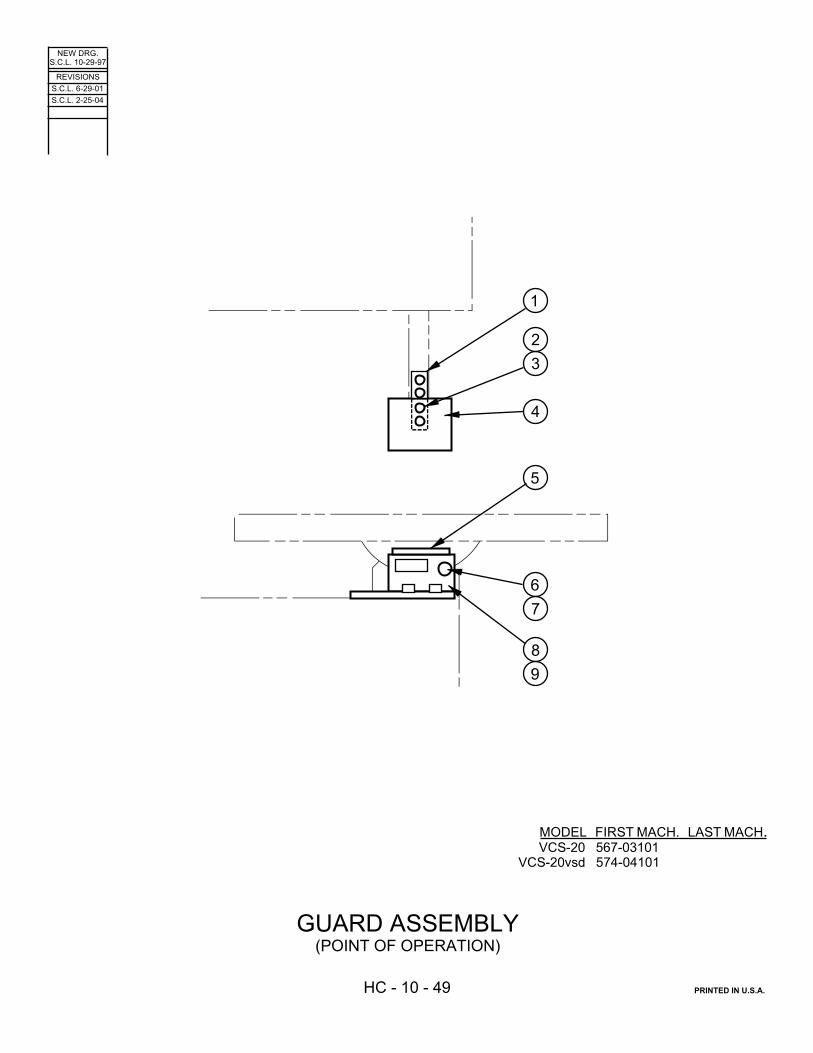
��������������� �# #�
�������
�� ���� ��# �������������
����������������������������
�$��������� '&���������&�������)
!
�
�
"
�
�
�
#
�
�����" �# ��
������ �� ��
���������������� � �� �"� �!���� ����� ��� �����

CODE NO. HC-10-49________________________
GUARD ASSEMBLY
INDEX PART DESCRIPTION UNITS PERNO. NO. ASS'Y.Ref. 417086H Guard Assembly (Point of Operation)1 146046 . Thumb Screw Assembly ........................................................................ 2
131086 . . Knob..................................................................................................... 1198219 . . Screw, Soc. Hd. Cap #10-24NC x 3/8.................................................. 1
2 203546 . Spacer.................................................................................................... 23 319337 . Upper Guard (Plexiglas)......................................................................... 14 417085H . Telescoping Guard................................................................................. 15 417084H . Lower Guard .......................................................................................... 16 203145 . Escutcheon (Guard Position) ................................................................. 17 133372 . Thumb Screw......................................................................................... 18 203098 . Nut Plate 1/4-20NC ................................................................................ 1

�������������� �� ��
�������
�� ��� ���� �������������
����������������������������� �� �"� �����
� ����� ��� �����
����������
��!��"��
#
��
��
��
�!
��
��
�"
��
��
�#
��
��
�� �! �� ��
�"
��
��
�# !� !�
!�
!!

CODE NO. C-2-114____________________
HEAD ASSEMBLY
INDEX PART DESCRIPTION UNITS PERNO. NO. ASS'Y.Ref. 520279 Head Assembly1 120627 . Pin ......................................................................................................... 12 35-009613 . Retaining Ring ....................................................................................... 23 004265 . Spring Pin .............................................................................................. 24 198264 . Screw, Soc. Hd. Cap 5/16-18NC x 2 ..................................................... 35 199323 . Washer, Lock 5/16 Std. ......................................................................... 36 198440 . Screw, Soc. Set 5/16-18NC x 1 ............................................................ 37 504621 . Head Casting ........................................................................................ 18 402598 . Bandwheel Assembly (See Detail) ........................................................ 19 415369 . Head Slide Weldment ........................................................................... 110 178228 . Screw, Soc. Set 1/4-20NC x 5/8 (Self Locking, Half Dog Pt.) ............... 211 302346 . Wheel Hinge Assembly (See Detail) ..................................................... 112 319429 . Band Tension Screw Sub-Assembly ..................................................... 1
203548 . . Adaptor ................................................................................................ 1139123 . . Screw .................................................................................................. 1004261 . . Spring Pin ............................................................................................ 1
13 199132 . Nut, Hex. Jam 1/2-13NC ....................................................................... 214 004259 . Spring Pin .............................................................................................. 115 199266 . Washer, Flat 1/2 S.A.E. Std. ................................................................. 216 35-002810 . Thrust Bearing ....................................................................................... 117 144062 . Angle ..................................................................................................... 118 319252 . Lock Handle .......................................................................................... 119 5-001506 . Bearing Locknut .................................................................................... 120 5-001507 . Bearing Lockwasher .............................................................................. 121 319251 . Tilting Screw Handle (w/Stud) ............................................................... 122 35-008761 . Compression Spring .............................................................................. 123 199267 . Washer, Flat 5/8 S.A.E. Std. ................................................................. 124 142250 . Band Tension Pointer ............................................................................ 125 139122 . Bracket .................................................................................................. 126 198001 . Screw, Hex. Hd. Cap #10-24NC x 1/2 .................................................. 227 199320 . Washer, Lock #10 Std........................................................................... 228 199111 . Nut, Hex. #10-24NC .............................................................................. 229 117737 . Escutcheon (Band Tension) (Inch/English) ........................................... 1
131424 . Escutcheon (Band Tension) (Metric/International) ................................ 130 199123 . Nut, Hex. Jam 5/16-18NC ..................................................................... 231 163080 . Retaining Compound (Loctite #271 ) .................................................... A.R.32* 316925 . Guard Weldment (Standard) ................................................................. 133* 216836 . Post Assembly (Standard) (See Detail) ................................................ 1 * 404971 . Post Elevating Handwheel Assembly (Standard - Optional) (See Detail) 1
*NOTE: See Extra Work Height Assembly If Applicable.
Following Not Shown:148368 . Escutcheon (Post - Raise/Lower) (International) .................................. 1199396 . Screw, Rd. Hd. Drive #2 x 3/16 ............................................................. 3

�������������� �� ��
�������
�� ��� ��" �������������
����������������������������������������������� �� �"� �!���
� ����� ��� �����
���������������� '����������������)
����������������������
�
�
!
�
�
"
��
#
��
��
��
�!
��
��
�"
��
��
�#
��
��

CODE NO. HC-8-16______________________
MIST COOLANT ASSEMBLY
INDEX PART DESCRIPTION UNITS PERNO. NO. ASS'Y.Ref. 517518H Mist Coolant Assembly1 002004 . Barbed Insert ......................................................................................... 12 35-006888 . Hose Clamp .......................................................................................... 13 203818 . Anchor Connection ................................................................................ 14 319526 . Orifice (.038) (Brass) ............................................................................. 15 201746 . Close Nipple (Brass) ............................................................................. 16 197094 . Neoprene Hose 11/16 O.D. (Black) ...................................................... A.R.7 5-004520 . 90° Street Elbow .................................................................................... 18 128179 . Barbed Insert ......................................................................................... 19 35-006888 . Hose Clamp .......................................................................................... 110 303956H . Bracket .................................................................................................. 111 199476 . Screw, Rd. Hd. Self-Tap 1/4-20NC x 3/4 .............................................. 212 136918 . Bottle Assembly ..................................................................................... 113 197144 . Plastic Tubing 3/8 O.D. (Clear) ............................................................. A.R.14 104713 . Hose Clamp .......................................................................................... 215 038303 . Coolant Manifold Assembly (Standard) ................................................. 1
038304 . Coolant Manifold Assembly (19” Work Height) ..................................... 1307334 . Coolant Manifold Assembly (25” Work Height) ..................................... 1311565 . Coolant Manifold Assembly (31” Work Height) ..................................... 1
16 172530 . . Coolant And Air Hose (Standard) ........................................................ 1172531 . . Coolant And Air Hose (19” Work Height) ............................................ 1172532 . . Coolant And Air Hose (25” Work Height) ............................................ 1172533 . . Coolant And Air Hose (31” Work Height) ............................................ 1172529 . . . Connector .......................................................................................... 1197322 . . . Segmented Hose (Specify Length) ................................................... A.R.172528 . . . Nozzle ............................................................................................... 1
17 108116 . 90° Barbed Insert .................................................................................. 118 5-027507 . . Sight Feed Valve ................................................................................. 119 119910H . . Manifold ............................................................................................... 120 14-014528 . Close Nipple .......................................................................................... 121 121061 . . Coolant Tube Assembly ..................................................................... 1
197140 . . . Nylon Tubing .089 O.D. (Cut to Length) ............................................ A.R.136893 . . . Glue (Meta Grip #3802) .................................................................... A.R.119912 . . . Pipe Plug ........................................................................................... 1

�������������� �� ��
�������
�� ��� ���� �������������
����������������������������
���������������
�
�!
�
��
#
�� "�
� ����� ��� �����

CODE NO. HC-5-127________________________
MOTOR BASE ASSEMBLY
INDEX PART DESCRIPTION UNITS PERNO. NO. ASS'Y.Ref. Motor Base Assembly1 518409 . Motor Base Plate .................................................................................... 12 198182 . Screw, Hex. Hd. Cap 3/8-16NC x 1-1/4 ................................................. 4
198030 . Screw, Hex. Hd. Cap 5/16-18NC x 1-1/4 (Single Phase) ....................... 43 199302 . Washer, Flat 3/8 Wrought ...................................................................... 4
199301 . Washer, Flat 5/16 Wrought (Single Phase) ........................................... 44 199126 . Nut, Hex. 3/8-16NC ................................................................................ 4
199122 . Nut, Hex. 5/16-18NC (Single Phase) ..................................................... 45 322011 . Pulley (60 Hz) ......................................................................................... 1
322010 . Pulley (50 Hz) ......................................................................................... 1308824 . Pulley (115V/60 Hz, 1 Phase) ................................................................ 1321368 . Pulley (220V/50 Hz, 1 Phase) ............................................................... 1
6 198425 . Screw, Soc. Set 1/4-20NC x 1/2 ............................................................ 17 209621 . Electric Motor (200V, 220V, 230V, 380V- 415V, 460V) ......................... 1
209622 . Electric Motor (575V) ............................................................................. 1133879 . Electric Motor (115V/60 Hz, 1 Phase) .................................................... 1209595 . Electric Motor (220V/50 Hz, 1 Phase) .................................................... 1
8 015835 . Cord Grip Connector .............................................................................. 19 014411 . Flange Washer ....................................................................................... 110 019543 . Bond Nut ................................................................................................ 1
Following Not Shown:205642 . Motor Terminal Block (50 Hz Only) ........................................................ 1

�������������� �� ��
�������
�� ��� ���� �������������
����������������������������� �� �"� �����
� ����� ��� �����
&��������
�
�
!
�
�
"
�
�
#
��
��
��

CODE NO. HC-2-115________________________
POST ASSEMBLY
INDEX PART DESCRIPTION UNITS PERNO. NO. ASS'Y.Ref. 216836 Post Assembly (Standard)Ref. 216837 Post Assembly (19” Work Height)Ref. 216938 Post Assembly (25” Work Height)Ref. 216839 Post Assembly (31” Work Height)1 417400 . Post (Standard) ..................................................................................... 1
418468 . Post (19” Work Height) ......................................................................... 1418780 . Post (25” Work Height) ......................................................................... 1417630 . Post (31” Work Height) ......................................................................... 1
2 417394 . Post Slide Casting ................................................................................. 13 204849 . Lockscrew Sub-Assembly ..................................................................... 1
203548 . . Adaptor ................................................................................................ 1004261 . . Spring Pin ............................................................................................ 1204848 . . Brass Stud ........................................................................................... 1
4 204850 . Spring Plunger ....................................................................................... 25 198280 . Screw, Soc. Hd. Cap 3/8-16NC x 1-1/4 ................................................ 46 199325 . Washer, Lock 3/8 Std. ........................................................................... 47 319741 . Post Slide Plate ..................................................................................... 18 112328 . Screw, Soc. Hd. Shoulder 5/16-18NC x 1/2 .......................................... 49 198698 . Screw, Fill. Hd. Mach. #10-24NC x 1/2 ................................................. 210 198459 . Screw, Soc. Set 3/8-24NF x 1 ............................................................... 411 004282 . Spring Pin .............................................................................................. 212 318807 . Guard Stop Bracket ............................................................................... 1

�������������� �� ��
�������
�� ��� ���" �������������
����������������������������� �� �"� �!���
� ����� ��� �����
&����������������������������
�
!
�
�
�
�
#
�!
�� �� �" ��
��
�#
��
����
�!
��
���"
��
��
�
"
��
��

CODE NO. HC-2-116________________________
POST ELEVATING HANDWHEEL ASSEMBLY
INDEX PART DESCRIPTION UNITS PERNO. NO. ASS'Y.Ref. 404971 Post Elevating Handwheel Assembly (Standard)Ref. 407860 Post Elevating Handwheel Assembly (18” and 19” Work Heights)Ref. 407729 Post Elevating Handwheel Assembly (24” and 25” Work Heights)Ref. 407618 Post Elevating Handwheel Assembly (30” and 31” Work Heights)1 198245 . Screw, Soc. Hd. Cap 1/4-20NC x 1-1/2 ................................................. 22 199374 . Washer, Lock 1/4 Shakeproof ............................................................... 23 303029 . Post (Standard) ...................................................................................... 1
306242 . Post (18” and 19” Work Heights) ........................................................... 1306243 . Post (24” and 25” Work Heights) ........................................................... 1306244 . Post (30” and 31” Work Heights) ........................................................... 1
4 198242 . Screw, Soc. Hd. Cap 1/4-20NC x 1 ........................................................ 45 198576 . Screw, Soc. Set 5/16-18NC x 3/4 (Flat Pt.) ............................................ 46 303030 . Cover ...................................................................................................... 17 125566 . Bevel Gear ............................................................................................. 18 004240 . Spring Pin ............................................................................................... 19 016063 . Thrust Bearing ........................................................................................ 110 133113 . Tubing .................................................................................................... 111 404970 . Housing .................................................................................................. 112 130751 . Grip Ring ................................................................................................ 113 5-013309 . Spacer .................................................................................................... A.R.14 004263 . Spring Pin ............................................................................................... 115 120922 . Bearing ................................................................................................... 216 038643 . Handwheel ............................................................................................. 117 123901 . Pin .......................................................................................................... 118 104690 . Handle .................................................................................................... 119 004259 . Spring Pin ............................................................................................... 120 198410 . Screw, Soc. Set #10-24NC x 1/4 ........................................................... 121 198422 . Screw, Soc. Set 1/4-20NC x 1/4 ............................................................ 122 003971 . Spring ..................................................................................................... 123 140765 . Friction Plug ........................................................................................... 124 004259 . Spring Pin ............................................................................................... 125 125567 . Bevel Gear ............................................................................................. 126 132667 . Shaft (Standard) ..................................................................................... 1
143983 . Shaft (18” and 19” Work Heights) .......................................................... 1143984 . Shaft (24” and 25” Work Heights) .......................................................... 1143985 . Shaft (30” and 31” Work Heights) .......................................................... 1
27 132666 . Nut .......................................................................................................... 1

�� ���� �" �������������
��&�����������
� � "
��#����
�
�
!
��������������# �# #�
�������
������ �� ��
�������������������������������������������� � �� �"� �!���
� ����� ��� �����

CODE NO. HC-10-6____________________
RIP FENCE ASSEMBLY
INDEX PART DESCRIPTION UNITS PERNO. NO. ASS'Y.Ref. 047779 Rip Fence Assembly1 5-016302 . Clamp Guide .......................................................................................... 12 198278 . Screw, Soc. Hd. Cap 3/8-16NC x 3/4 ..................................................... 2
34-005414 . Spacer Washer (If Supplied) .................................................................. 23 35-005178 . Rip Fence Sub-Assembly ....................................................................... 14 35-000544 . . Clamp ................................................................................................... 15 198278 . . Screw, Soc. Hd. Cap 3/8-16NC x 3/4 ................................................... 26 35-000546 . . Work Guide .......................................................................................... 17 5-016403 . . Clamp Bar Screw ................................................................................. 28 198425 . . Screw, Soc. Set 1/4-20NC x 1/2 .......................................................... 29 5-016303 . . Clamp Bar ............................................................................................ 110 34-006504 . . Spring Clip ............................................................................................ 211 117670 . . Handwheel Assembly ........................................................................... 1
Following Not Shown:203556 . Tag (Rip Fence Alignment) .................................................................... 1

���������������# �� #�
�������
�� ��� ��� �������������
����$�����������'�������)
� � " � � !
�
�
$&&�������� �����������
����$������������� ����$���������
� �
!
�
�
"
�
�
! � �
���������&�������
������ �� ��
�������������������������������������������� � �� �"� �!���
� ����� ��� �����

CODE NO. HC-7-20________________________
SAW GUIDE ASSEMBLIES
INDEX PART DESCRIPTION UNITS PERNO. NO. ASS'Y.Ref. 028081 Upper Saw Guide Assembly (High Speed) (1/16”-1/2”)1* 011529 . Ball Bearing ......................................................................................... 12 011541 . Retaining Ring (If Supplied) ................................................................ 13* 018415 . Bearing Cap ........................................................................................ 14* 176845 . Spacer ................................................................................................ 15 198238 . Screw, Soc. Hd. Cap 1/4-20NC x 5/8................................................... 26 34-008502 . Insert Washer ...................................................................................... 27 027981 . Upper Saw Guide Block ...................................................................... 18 137339 . Hole Plug (If Supplied) ........................................................................ 1
Ref. 028082 Lower Saw Guide Assembly (High Speed) (1/16”-1/2”)1* 011529 . Ball Bearing ......................................................................................... 12 011541 . Retaining Ring (If Supplied) ................................................................ 13* 018415 . Bearing Cap ........................................................................................ 14* 176845 . Spacer ................................................................................................ 15 198238 . Screw, Soc. Hd. Cap 1/4-20NC x 5/8................................................... 26 34-008502 . Insert Washer ...................................................................................... 27 027983 . Lower Saw Guide Block ...................................................................... 18 137339 . Hole Plug (If Supplied) ........................................................................ 1
*NOTE: When ordering any of the marked items, ordering #085369 - Bearing Replacement Kit is recommended.
SAW GUIDE INSERT GAGE34-008320 . Insert Gage (.025) ............................................................................... 113-008303 . Insert Gage (.032) ............................................................................... 113-009307 . Insert Gage (.035) ............................................................................... 134-008506 . Box (For Inserts and Gages) ............................................................... 1
SAW GUIDE INSERT SELECTIONSTEEL SIZE CARBIDE004499 1/16”004498 3/32”004497 1/8” 141759004496 3/16”004495 1/4” 016168003960 3/8” 016170003959 1/2” 013291003958 5/8” 105894003957 3/4” 013292003956 1” 008982

���������������# �# #�
�������
�� ��� ��� �������������
����$�����������'������� &�)
����$���������
����$�������������� ���� ��$� �����$��������� '��������������( $&)
���� ��$� �����$��������� '������������( $&)
&�����������$��������� '�,�"-� ��,�-��������)
$&&��������
�����������
� � ! � � "
�
�#��
��
��
!�
�
"
�
$&&��������
� � ! � �
"
�
�
��
!�
�
"
�
�����������
� � ! � �
$&&��������
"
�
�����������
��������$� �����
� � ! � �
� � ! �
������ �� ��

CODE NO. HC-7-18____________________
SAW GUIDE ASSEMBLIES
INDEX PART DESCRIPTION UNITS PERNO. NO. ASS'Y.HEAVY DUTY SAW GUIDE ASSEMBLY (CARBIDE BACK-UP)
Ref. 119918 Upper Saw Guide Assembly (1/16” - 1/2”)Ref. 017861 Upper Saw Guide Assembly (5/8” - 3/4”)Ref. 303011 Upper Saw Guide Assembly (1”)Ref.* 120119 Upper Saw Guide Assembly (1” W/
Coolant Line)1 198238 . Screw, Soc. Hd. Cap 1/4-20NC x 5/8
(1/16” – 1/2”) ................................... 2198242 . Screw, Soc. Hd. Cap 1/4-20NC x 1
(5/8” – 3/4”) ..................................... 2198244 . Screw, Soc. Hd. Cap 1/4-20NC x 1-1/4
(1”; Coolant Line) ............................ 22 34-008502 . Insert Washer ................................. 23 198445 . Screw, Soc. Set 5/16-24NF x 1/2
(5/8”, 3/4”, 1”) .................................. 1033509 . Coolant Nozzle (Coolant Line) ........ 1
4 038076 . Upper Saw Guide Block (1/16” - 1/2”) 1025252 . Upper Saw Guide Block (5/8”, 3/4”) .... 1025253 . Upper Saw Guide Block (1”) ........... 1033631 . Upper Saw Guide Block (W/Coolant
Line) ............................................... 15 135441 . Locknut (5/8”, 3/4”, 1”) .................... 16 133202 . Pipe Plug (5/8”, 3/4”, 1”) .................. 1
108116* . 90° Barbed Insert (Coolant Line) ..... 17 018337 . Guide Guard (5/8”, 3/4”, 1”) ............. 18 017218 . Bearing Cap Ass’y. (Includes Carbide) 19 011529 . Bearing ........................................... 210 011541 . Retaining Ring ................................ 111 200306 . Spacer (Between Bearings) ............ 1
* Models 1612-3, 2612-2H, 2613-2, 3613-3, 6013-3, 6013-H3 Only.NOTE: If your Machine has 2 Coolant Lines to the Upper Saw Guide,Delete This Item and Replace With the Following:
109452 . Swivel Joint ..................................... 1016001 . Barbed Insert .................................. 2
Ref. 119001 Lower Saw Guide Assembly (1/16” - 1/2”)Ref. 018168 Lower Saw Guide Assembly (5/8” - 3/4”)Ref. 017732 Lower Saw Guide Assembly (1”)1 017218 . Bearing Cap Ass’y. (Includes Carbide)12 011529 . Bearing ........................................... 23 011541 . Retaining Ring ................................ 14 200306 . Spacer (Between Bearings) ............ 15 037738 . Lower Saw Guide Block (1/16” - 1/2”) 1
025258 . Lower Saw Guide Block (5/8”, 3/4”) .... 1025257 . Lower Saw Guide Block (1”) ............ 1
6 198238 . Screw, Soc. Hd. Cap 1/4-20NC x 5/8 (1/16” – 1/2”) ................................... 2
198242 . Screw, Soc. Hd. Cap 1/4-20NC x 1 (5/8” – 3/4”) ..................................... 2
198244 . Screw, Soc. Hd. Cap 1/4-20NC x 1-1/4 (1”; Coolant Line) ............................ 2
7 34-008502 . Insert Washer ................................. 2
SAW GUIDE INSERT SELECTION
STEEL SIZE CARBIDE004499 1/16”004498 3/32”004497 1/8” 141759004496 3/16”004495 1/4” 016168003960 3/8” 016170003959 1/2” 013291003958 5/8” 105894003957 3/4” 013292003956 1” 008982
INDEX PART DESCRIPTION UNITS PERNO. NO. ASS'Y.HEAVY DUTY SAW GUIDE ASSEMBLY (STEEL BACK-UP)
Ref. 120143 Upper Saw Guide Assembly (1/16” - 1/2”)Ref. 011528 Upper Saw Guide Assembly (5/8” - 3/4”)Ref. 011530 Upper Saw Guide Assembly (1”)1 198244 . Screw, Soc. Hd. Cap 1/4-20NC x 1-1/4
(1/16” – 1/2”, 1”) .............................. 2198242 . Screw, Soc. Hd. Cap 1/4-20NC x 1
(5/8” – 3/4”) ..................................... 22 34-008502 . Insert Washer ................................. 23 198445 . Screw, Soc. Set 5/16-24NF x 1/2
(5/8”, 3/4”, 1”) ................................. 14 038076 . Upper Saw Guide Block (1/16” - 1/2”) 1
025252 . Upper Saw Guide Block (5/8”, 3/4”) .... 1025253 . Upper Saw Guide Block (1”) ........... 1
5 120369 . Pipe Plug (5/8”, 3/4”, 1”) ................. 16 011540 . Bearing Cap ................................... 17 011529 . Bearing ........................................... 28 011541 . Retaining Ring ................................ 19 200306 . Spacer (Between Bearings) ............ 1
Ref. 120142 Lower Saw Guide Assembly (1/16” - 1/2”)Ref. 011543 Lower Saw Guide Assembly (5/8” - 3/4”)Ref. 011542 Lower Saw Guide Assembly (1”)1 011540 . Bearing Cap ................................... 12 011529 . Bearing ........................................... 23 011541 . Retaining Ring ................................ 14 200306 . Spacer (Between Bearings) ............ 15 037738 . Lower Saw Guide Block (1/16” - 1/2”) 1
025258 . Lower Saw Guide Block (5/8”, 3/4”) .... 1025257 . Lower Saw Guide Block (1”) ........... 1
6 198244 . Screw, Soc. Hd. Cap 1/4-20NC x 1-1/4 (1/16” - 1/2”, 1”) .............................. 2
198242 . Screw, Soc. Hd. Cap 1/4-20NC x 1 (5/8” – 3/4”) ..................................... 2
7 34-008502 . Insert Washer ................................. 2
PRECISION SAW GUIDE ASSEMBLY (1/16” – 1/2”)
Ref. 011519 Precision Upper Saw Guide Assembly1 198238 . Screw, Soc. Hd. Cap 1/4-20NC x 5/8 22 34-08502 . Insert Washer ................................. 23 198445 . Screw, Soc. Set 5/16-24NF x 1/2 .... 14 025249 . Upper Saw Guide Block .................. 15 198501 . Screw, Soc. Set #8-32NC x 1/4 (Cone Pt.) 16 120369 . Pipe Plug ........................................ 17 34-080092 . Bearing Sub-Assembly (See Detail) 1
Ref. 011507 Precision Lower Saw Guide Assembly1 198238 . Screw, Soc. Hd. Cap 1/4-20NC x 5/8 22 34-008502 . Insert Washer ................................. 23 34-008009 . Bearing Sub-Assembly (See Detail) 14 025247 . Lower Saw Guide Block .................. 15 198501 . Screw, Soc. Set #8-32NC x 1/4 (Cone Pt.) 1
Ref. 34-008009 . Bearing Sub-Assembly1 34-008418 . . Shaft ............................................. 12 35-009043 . . Bearing ......................................... 13 34-008312 . . Washer ......................................... 14 34-008309 . . Roller Seal .................................... 1
SAW GUIDE INSERT SELECTION
34-008320 . Insert Gage (.025) .......................... 134-008303 . Insert Gage (.032) .......................... 134-008307 . Insert Gage (.035) .......................... 134-008506 . Box (For Inserts and Gages) ........... 1

���������������# !� #�
�������
�� ��� ��# �������������
����$�����������'�������� &�)
�
�
!
�
�
"��
�
�
!
�
�
$&&��������
�����������
� �
!
� �
� �
!
� �
$&&��������
�����������
� &���� ������������$��������� � &����� ������������$���������
�
�
!
�
� �
�
!
�
�
��( $&�������
����������
�
�
!
�
�
�
�
!
�
�
��( $&������� ����������
������ �� ��

CODE NO. HC-7-19 _________
_________
SAW GUIDE ASSEMBLIES
INDEX PART DESCRIPTION UNITS PERNO. NO. ASS'Y.
TYPE I – ROLLER SAW GUIDE ASSEMBLY
Ref. 029256 1/4” Upper Roller Saw Guide AssemblyRef. 029258 3/8” Upper RollerSaw Guide AssemblyRef. 029506 1/2” Upper Roller Saw Guide Assembly1 See Below . Back-Up Roller Assy (See Detail) ... 12 028960 . Upper Guide Block .......................... 13 198239 . Screw, Soc. Hd. Cap 1/4-20NC x 3/4 . 24 199321 . Washer, Lock 1/4 Std. .................... 25 See Below . Side Roller Assy (See Detail) .......... 1
Ref. 029257 1/4” Lower Roller Saw Guide AssemblyRef. 029259 3/8” Lower Roller Saw Guide AssemblyRef. 029505 1/2” Lower Roller Saw Guide Assembly1 See Below . Back-Up Roller Assy (See Detail) ... 12 028961 . Lower Guide Block .......................... 13 199239 . Screw, Soc. Hd. Cap 1/4-20NC x 3/4 . 24 199321 . Washer, Lock 1/4 Std. .................... 25 See Below . Side Roller Assy (See Detail) .......... 1
TYPE I – ROLLER ASSEMBLIES
Ref. 028982 1/4” Back-Up Roller AssemblyRef. 028978 3/8” Back-Up Roller AssemblyRef. 028976 1/2” Back-Up Roller Assembly1 100046 . Retaining Ring ................................. 22 011541 . Retaining Ring ................................. 13 018296 . Shaft ................................................ 14 011529 . Bearing ............................................ 15 028983 . 1/4” Back-up Roller .......................... 1
028979 . 3/8” Back-up Roller .......................... 1028977 . 1/2” Back-up Roller .......................... 1
Ref. 028984 1/4” Side Roller AssemblyRef. 028980 3/8” Side Roller AssemblyRef. 028974 1/2” Side Roller Assembly1 100046 . Retaining Ring ................................ 22 011541 . Retaining Ring ................................ 13 018296 . Shaft ............................................... 14 011529 . Bearing ........................................... 15 028985 . 1/4” Side Roller ............................... 1
028981 . 3/8” Side Roller ............................... 1028975 . 1/2” Side Roller ............................... 1
TYPE II – ROLLER SAW GUIDE ASSEMBLY
Ref. 109517 Upper Saw Guide Block Assembly1 198236 . Screw, Soc. Hd. Cap 1/4-20NC x 1/2 . 12 199321 . Washer, Lock 1/4 Std. .................... 13 016001 . Barbed Insert .................................. 14 198448 . Screw, Soc. Set 3/8-16NC x 3/8 ...... 25 0-01741 . Plug ................................................ 26 0-33636 . Coolant Guard ................................ 17 0-33517 . Upper Saw Guide Block .................. 18 0-33509 . Coolant Nozzle ............................... 1
Ref. 017215 Lower Saw Guide Block Assembly1 002140 . Chip Deflector ................................. 12 198235 . Screw, Soc. Hd. Cap 1/4-20NC x 3/8 . 23 198449 . Screw, Soc. Set 3/8-16NC x 1/2 ...... 24 001741 . Plug ................................................ 25 027743 . Lower Saw Guide Block .................. 1
Not Shown (For Both Upper and Lower Guides):131798 . Cloth Bag ........................................ 1
INDEX PART DESCRIPTION UNITS PERNO. NO. ASS'Y.
TYPE II ROLLER ASSEMBLIESRef. 020798 1/4” Back-Up Roller AssemblyRef. 020808 3/8” Back-Up Roller AssemblyRef. 020295 1/2” Back-Up Roller AssemblyRef. 021071 5/8” Back-Up Roller AssemblyRef. 020296 3/4” Back-Up Roller AssemblyRef.* 028968 1” Back-Up Roller Assembly1 001303 . Retaining Ring ................................ 22 001568 . Retaining Ring ................................ 13 013530 . Spindle ........................................... 14 001779 . Bearing ........................................... 15 013532 . 1/4” Back-Up Roller ........................ 1
013541 . 3/8” Back-Up Roller ........................ 1013534 . 1/2” Back-Up Roller ........................ 1013543 . 5/8” Back-Up Roller ........................ 1013536 . 3/4” Back-Up Roller ........................ 1100757 . 1” Back-Up Roller ........................... 1
Ref. 020799 1/4” Side Roller AssemblyRef. 020807 3/8” Side Roller AssemblyRef. 020292 1/2” Side Roller AssemblyRef. 021072 5/8” Side Roller AssemblyRef. 020293 3/4” Side Roller AssemblyRef.* 028967 1” Side Roller Assembly1 001303 . Retaining Ring ................................ 22 001568 . Retaining Ring ................................ 13 013530 . Spindle ........................................... 14 001779 . Bearing ........................................... 15 013531 . 1/4” Side Roller ............................... 1
013540 . 3/8” Side Roller ............................... 1013533 . 1/2” Side Roller ............................... 1013542 . 5/8” Side Roller ............................... 1013535 . 3/4” Side Roller ............................... 1100758 . 1” Side Roller .................................. 1
*NOTE: To Be Used With Flanged Rubber-tired WheelsUsing 1/4”, 1/2”, 3/4” or 1” Bands. Also Used WithSteel Fanged or Rubber Crowned Wheels Using
1” Band Only.

�������������� �� ��
�������
�� �!� �#! �������������
����������������������������
������������$�����������
�
�
! � "
�
�
#
�������!��
��
�"
�� �� �# ��
��
���!
��
��
�"
� �� �"� �!���� ����� ��� �����
��������������

CODE NO. HC-3-93________________________
TABLE AND TRUNNION ASSEMBLY
INDEX PART DESCRIPTION UNITS PERNO. NO. ASS'Y.Ref. 172512 Table and Trunnion Assembly (26" x 26")1 040645 . Trunnion ................................................................................................ 12 198065 . Screw, Hex. Hd. Cap 1/2-13NC x 1 ...................................................... 43 199327 . Washer, Lock 1/2 Std. ........................................................................... 44 316903 . Center Plate (Oval) ............................................................................... 16 514113 . Table (26" x 26") ................................................................................... 17 003861 . Escutcheon ........................................................................................... 18 199401 . Screw, Rd. Hd. Drive #6 x 3/8 ............................................................... 29 512731 . Cradle .................................................................................................... 110 198046 . Screw, Hex. Hd. Cap 3/8-16NC x 1 ...................................................... 211 199332 . Washer, Lock 3/8 Std. ........................................................................... 212 024244 . Lower Post Block .................................................................................. 113 35-000516 . Dowel Pin .............................................................................................. 214 34-003315 . Pointer ................................................................................................... 115 198839 . Screw, Rd. Hd. Mach. #6-32NC x 5/16 ................................................. 116 199273 . Washer, Flat #6 S.A.E. Std. .................................................................. 217 198046 . Screw, Hex. Hd. Cap 3/8-16NC x 1 ...................................................... 218 199264 . Washer, Flat 3/8 S.A.E. Std. ................................................................. 219 004599 . Clamp .................................................................................................... 120 039464 . Head ...................................................................................................... 121 010501 . Spacer ................................................................................................... 122 199141 . Nut, Hex. 3/4-16NF ............................................................................... 123 199268 . Washer, Flat 3/4 S.A.E. Std. ................................................................. 124 016351 . Dowel Pin .............................................................................................. 225 198291 . Screw, Soc. Hd. Cap 1/2-3NC x 3/4 ...................................................... 326 198106 . Screw, Hex. Hd. Cap 3/4-16NF x 5 ....................................................... 1

��������������� � ��
�������
�� �!� ��� �������������
����������� '��%��)
����������������������������������������������� �� �"� �!���� ����� ��� �����
� � ! � � " � � #
��
��
�!�����"��
��

CODE NO. HC-3-71________________________
TABLE ASSEMBLY
INDEX PART DESCRIPTION UNITS PERNO. NO. ASS'Y.Ref. 420758 Table Assembly (Fixed)1 420756 . Table Weldment .............................................................................. 12 198179 . Screw, Hex. Hd. Cap 3/8-16NC x 3/4 .............................................. 43 199325 . Washer, Lock 3/8 Std. ..................................................................... 44 198046 . Screw, Hex. Hd. Cap 3/8-16NC x 1 ................................................. 25 199325 . Washer, Lock 3/8 Std. ..................................................................... 26 219578 . Sawing Slot Clamp Bar .................................................................... 17 024244 . Lower Post Block ............................................................................. 18 198065 . Screw, Hex. Hd. Cap 1/2-13NC x 1 ................................................. 39 199335 . Washer, Lock 1/2 Std. ..................................................................... 310 420755 . Table Support Angle ........................................................................ 211 198179 . Screw, Hex. Hd. Cap 3/8-16NC x 3/4 .............................................. 412 199325 . Washer, Lock 3/8 Std. ..................................................................... 413 420754 . Table/Guide Mounting Plate ............................................................ 114 35-000516 . Dowel Pin ......................................................................................... 215 198046 . Screw, Hex. Hd. Cap 3/8-16NC x 1 ................................................. 216 199325 . Washer, Lock 3/8 Std. ..................................................................... 217 016351 . Dowel Pin ......................................................................................... 2

�������������� �� ��
�������
�� ��� ��� �������������
���������������
����������������&�������
�
�
!
�
�
"
�
�
#
��
��
�! �� �� �"
��
�� �# �� �� �� �! ��
���"
��
��
�#
!�
!�
!�!!!�
!�
!"
!�
!�!#�������!�����"
��
��
�#
��
����
��
��
�!
�������������������������������������������� � �� �"� �!���
� ����� ��� �����

CODE NO. HC-4-47________________________
TRANSMISSION ASSEMBLYINDEX PART DESCRIPTION UNITS PERNO. NO. ASS'Y.Ref. 506827 Transmission Assembly1 108557 . Bearing .................................................................................................................... 12 5-004303 . Countershaft Bearing Cover .................................................................................... 13 5-004309 . Gasket ..................................................................................................................... 14 5-004602 . Woodruff Key .......................................................................................................... 15 323106 . Bearing Cover ......................................................................................................... 16 213598 . Shaft Seal ................................................................................................................ 17 35-008688 . Retaining Ring ......................................................................................................... 18 307343 . Input Shaft Assembly .............................................................................................. 1
031737 . . Input Shaft And Clutch .......................................................................................... 1004283 . . Spring Pin .............................................................................................................. 1307344 . . Clutch .................................................................................................................... 1
9 100122 . Bearing .................................................................................................................... 110 175651 . Flinger (If Supplied) ................................................................................................. 111 35-008189 . Retaining Ring ......................................................................................................... 112 35-007538 . Retaining Ring ......................................................................................................... 113 002273 . Ball Bearing ............................................................................................................. 114 111692 . Snap Ring ............................................................................................................... 115 214190 . Shaft Seal ................................................................................................................ 116 164548 . Needle Bearing ....................................................................................................... 117 164547 . Inner Race ............................................................................................................... 118 143391 . Grease (Union 76 Unoba EP 2) .............................................................................. A.R.19 111449 . Shifter Fork Weldment ............................................................................................ 120 111451 . Shifter Clutch Assembly .......................................................................................... 1
048621 . . Shifter Clutch ......................................................................................................... 1111450 . . Ball Bearing ........................................................................................................... 1004209 . . Spring Pin .............................................................................................................. 3
21 35-000443 . Dowel Pin ................................................................................................................ 122 6-004421 . Clutch Gear ............................................................................................................. 123 147522 . Spacer ..................................................................................................................... 124 147523 . Ball Bearing ............................................................................................................. 125 408641 . Bearing Cover Plate ................................................................................................ 126 198239 . Screw, Soc. Hd Cap 1/4-20NC x 3/4 ....................................................................... 527 212668 . Black Silcon (Super Flex 598) ................................................................................. A.R.28 147524 . Oil Seal .................................................................................................................... 129 408637 . Output Shaft ............................................................................................................ 130 147521 . Seal Ring ................................................................................................................. 131 35-007192 . Woodruff Key .......................................................................................................... 232 152085 . Shim (.005) .............................................................................................................. A.R.33 152086 . Shim (.010) .............................................................................................................. A.R.34 152087 . Shim (.032) .............................................................................................................. A.R.35 152088 . Shim (.060) .............................................................................................................. A.R.36 147622 . Bearing Spacer ....................................................................................................... 137 108557 . Bearing .................................................................................................................... 138 506828 . Transmission Cover ................................................................................................ 139 198257 . Screw, Soc. Hd. Cap 5/16-18NC x 5/8 .................................................................... 440 013122 . Dowel Pin ................................................................................................................ 141 5-004311 . Gasket ..................................................................................................................... 142 054871 . Transmission Case ................................................................................................. 143 152157 . Magnetic Plug ......................................................................................................... 144 313681 . Countershaft And Pinion ......................................................................................... 145 5-004424 . Gear ........................................................................................................................ 146 103235 . Spacer ..................................................................................................................... 147 160149 . Escutcheon (If Supplied) ......................................................................................... 148 199396 . Screw, Rd. Hd. Drive #2 x 3/16 ............................................................................... 249 113737 . Pipe Plug ................................................................................................................. 150 138442 . Gear Oil ................................................................................................................... A.R.51 198005 . Screw, Hex. Hd. Cap 1/4-20NC x 3/8 ...................................................................... 452 120369 . Pipe Plug (1/8 NPT) ................................................................................................ 153 159133 . Screw, Soc. Hd. Cap 1/4-20NC x 1/2 (Low Head) ................................................. 454 17-013521 . 90° Street Elbow ..................................................................................................... 1

�������������� �� #�
�������
�� ��� �!" �������������
�������������� '&��������)
� � ! �
�"��#
������ �� ��
����������������������������� ����� ��� �����

CODE NO. ____HC-5-36______________________
VARIABLE ASSEMBLY
INDEX PART DESCRIPTION UNITS PERNO. NO. ASS'Y.Ref. 045423 Variable Assembly (6P-A Speedmaster)1 010861 . Oiler (If Supplied) ..................................................................................... 12 010857 . Sleeve ...................................................................................................... 13 024882 . Floating Sheave ....................................................................................... 14 028813 . Shaft (6P-A Speedmaster) .................................................................... 15 010859 . Plug (Either End of Shaft) ........................................................................ 16 024881 . End Sheave .............................................................................................. 27 198436 . Screw, Soc. Set 5/16-18NC x 3/8 ............................................................ 48 010496 . Oil Wick .................................................................................................... 39 001139 . Retaining Ring .......................................................................................... 1

�������������� �� ��
�������
�� ��� ��� �������������
����������������������������� ����� ��� �����
������������(����$� �����
�!
� � ! � � "
� � # �� �� �� �! ��
���"�����#
��
����
��

CODE NO. HC-4-48_ __ ______ ___ ____
VARIABLE LINKAGE SUB-ASSEMBLY
INDEX PART DESCRIPTION UNITS PERNO. NO. ASS'Y.Ref. 414268 Variable Linkage Sub-Assembly1 042535 . Handwheel ............................................................................................. 12 004259 . Spring Pin ............................................................................................... 13 142253 . Universal Joint ........................................................................................ 14 198422 . Screw, Soc. Set 1/4-20NC x 1/4 ............................................................ 25 004259 . Spring Pin ............................................................................................... 16 315180 . Variable Screw ....................................................................................... 17 174012 . Indicator Arm Sub-Assembly .................................................................. 1
118699 . . Arm ....................................................................................................... 1199292 . . Washer, Flat #8-S Brass ...................................................................... 135-006328 . . Swivel Block ......................................................................................... 1198690 . . Screw, Fill. Hd. Mach. #6-32NC x 3/8 .................................................. 1
8 198854 . Screw, Rd. Hd. Mach. #8-32NC x 1/2 .................................................... 29 35-007558 . Retaining Ring ........................................................................................ 110 002915 . Spacer (.0625) ....................................................................................... 111 126207 . Spring Washer (.099) ............................................................................. 212 315182 . Base Weldment ...................................................................................... 113 005956 . Adjusting Screw ..................................................................................... 314 199142 . Nut, Hex. Jam 3/4-16NF ........................................................................ 315 513017 . Arm ......................................................................................................... 116 006175 . Trunnion Pin ........................................................................................... 117 007979 . Spacer .................................................................................................... 218 5-013410 . Screw Stop Nut 1/2-13NC x 3/8 ............................................................. 419 199142 . Nut, Hex. Jam 3/4-16NF ........................................................................ 120 106110 . Belleville Washer .................................................................................... 121 124594 . Bushing .................................................................................................. 122 107280 . Shaft ....................................................................................................... 123 118116 . Handle .................................................................................................... 124 118117 . Pin .......................................................................................................... 1

���������������# �� #�
�������
�� ���� ��" �������������
���(���������.��������
��!��"�
������ �� ��
�������������������������������������������� � �� �"� �!���
� ����� ��� �����

CODE NO. HC-10-16______________________
WORK HOLDING JAW ASSEMBLY
INDEX PART DESCRIPTION UNITS PERNO. NO. ASS'Y.Ref. 5-013007 Work Holding Jaw Assembly1 5-013512 . Jaw Handle ............................................................................................. 22 5-013318 . Bracket ................................................................................................... 23 040678 . Work Holding Jaw Sub-Assembly .......................................................... 14 5-013110 . . Work Holding Jaw ................................................................................ 15 198892 . . Screw, Rd. Hd. Mach. 1/4-20NC x 5/16 ............................................... 66 5-013313 . . Sprocket ............................................................................................... 27 199015 . . Screw, Truss Hd. Mach. #10-24NC x 3/8 ............................................ 4


��������������� � ��
�������
�������������
���� ����������
������������������������������� �� �"� �!���
� ����� ��� �����
� ���������� ������������������������������ ��!"!#$
�����%&�'����� ��!"!#(
) � ��*�+,-� .&������� ��$�//(
��*,�&� �*�%&�'����� ��!"!#0
��.�1 �*�� ���,22��"��23 �4�$���*�.156�7 � 1,1
����23 �4!�(��*�.156�7&8 1,1
��*���%&�'����� ��$ ��(��0
)� 9 .����� �(�($��
�((�� &
�&9����%&�'����� ���/�//
�: 2����;�����7 3������&��
)2� ��3


MODEL FIRST SERIAL NO. LAST SERIAL NO.DBW-15 471-88101
PRINTED IN U.S.A.
PARTS and INSTRUCTION MANUALBUTTWELDER
PLEASE READ THIS MANUAL CAREFULLY BEFORE OPERATING THE BUTTWELDER!
For your information and future reference, pertinent data concerning yourbuttwelder should be written in the spaces provided above. This information isstamped on a plate attached to the front of your welder. Be sure to providewelder model and serial numbers with any correspondence or parts orders.
Specifications contained herein were in effect at the time this manual wasapproved for printing. Our policy is one of continuous improvement, reservesthe right, however, to change specifications or design at any time without noticeand without incurring obligations.
PB-413.2 (6-01)

TABLE OF CONTENTS
WELDER DIMENSIONS .......................... 1
WELDER FEATURES ............................. 2
INSTALLATION
Specifications .......................................................... 3Location .................................................................. 3Unpacking ............................................................... 3Blade Shear Installation .......................................... 3Electrical Installation ............................................... 3
OPERATION
General Description ................................................. 4Preparation For Welding .......................................... 4-5Making the Weld ..................................................... 5-6Grinding and Annealing Welded Bands .................... 6-7
MAINTENANCE
Lubrication .............................................................. 8Slide Bar Maintenance ............................................ 8Welder Jaw Maintenance ........................................ 8Jaw Alignment ......................................................... 8Jaw Gap Adjustments ............................................. 8Weld Upset Force Adjustment................................. 8Weld Lever Drag Spring ........................................... 9Maximum Jaw Gap Adjustment ............................... 9Blade Line-Up Guide Adjustment ............................. 9Final Jaw Alignment ................................................ 9
TROUBLE SHOOTING .................................. 10
ACCESSORIES
Blade Shear ............................................................ 11
REPLACEMENT PARTS
DBW-15 Buttwelder ................................................. 12-13Blade Shear ............................................................ 14-15Electrical Schematic ............................................... 16
81


1
WELDER DIMENSIONS
FRONT VIEWSIDE VIEW
(Inside Enclosure)
INCHES (± .03)MILLIMETERS (± 1 mm)
SIDE VIEW
NOTE: Portable Welder has theEnclosure and related parts.

2
WELDER FEATURES

3
INSTALLATIONAll “left”, “right”, “front” and “rear” designa-tions in this manual are as viewed by theoperator facing the control panel.
SPECIFICATIONS
1. This resistance-type buttwelder is capable of weld-ing various saw bands from 1/16 to 1 inch (1.5 to 25mm) wide and 0.025 to 0.035 inch (0.63 to 0.89 mm)in thickness.
LOCATION
1. There are three (3) primary factors to consider whenchoosing the buttwelder's location:
• The operator must have sufficient space foe easysaw band handling and welding.
• Sufficient space must be allowed so that a coiledsaw band will not injure persons passing nearby.
• There must be no flammable materials nearby thatmight be ignited by sparks from the welder.
UNPACKING
1. Carefully remove the buttwelder from its shipping box.Then: (a) Remove all packing materials; (b) Unpackthe Blade Shear and band thickness gage; (c) Placethe welder on a table in preparation for Blade Shearattachment.
2. Inspect the welder for broken or damaged parts. Re-fer to this manual's inside front cover for damageclaim procedures.
3. When assembling the blade shear to the welder, fol-low the directions on the instruction sheet SE-14 (6-99) provided with the Blade Shear.
BLADE SHEAR INSTALLATION
1. Mount the Blade Shear to the band sawing machineor to the portable buttwelder box with the 5/16-18NCx 3/4 cap screws provided. A bracket is also pro-vided for mounting the blade shear to the facing sur-face of the machine if desired.
ELECTRICAL INSTALLATION
Electrical installation must be made by au-thorized electrical maintenance personnelonly.
Incoming Power Connections.
Portable Welder
1. Connect the buttwelder to an electrical power linewith sufficient capacity to provide instantaneous loadspecified on the data plate. Also fuse according toamperage listed. Refer to the electrical schematicsupplied with your welder if necessary.
This buttwelder WILL NOT operate on directcurrent (DC).
2. Wiring must conform to local electrical codes. Tocontinue electrical connections: (a) Route the cus-tomer supplied power source through the back panelhole in the welder box; (b) Secure with an appropri-ate connector (customer supplied); (c) Attach theground wire to the ground stud inside the back panel;(d) Connect line "1" to the top of the disconnect switchT1; (e) Connect line "2" to the top of the disconnectswitch T2.
Machine Mounted Installation (208V, 230V Only)
1. Bring incoming power from the machine to the backof the welder. Then: (a) Connect the lines to theterminals shown in the illustration.
2. For all other voltages, refer to the electrical sche-matic furnished with the welder or machine for properelectrical connections.

4
OPERATIONGENERAL DESCRIPTION
1. Model DBW-15 is a resistance-type buttwelder. Itstwo (2) clamping jaws hold the butted saw band endstogether during the welding process. When the op-erator presses the Weld Lever, an electric currentflows through the butted saw band ends. This cre-ates enough heat to soften and join the band ends.
2. Pressing the Weld Lever also releases a springwhich causes the clamping jaws to force the sawband ends together (electric current shuts off beforethe movable jaw has completed its movement).
3. Final upset or "forging" occurs while the saw band isstill hot, but no longer being heated by its electricalenergy source.
PREPARATION FOR WELDING
It is important that both the saw band andbuttwelder be properly prepared for eachwelding operation.
Saw Band Preparation
1. Cutting. Cut the saw band to length using the bladeshear (if supplied) to insure that the blade ends areflat, square and smooth.
Use the Blade Shear to Cut the Saw Band.
2. Tooth Spacing. When preparing fine-pitched sawbands, one or more teeth on each side of the cutmust be ground off to insure uniformity of the sawband's weld cross-section area. This willalso insure:(a) Proper tooth spacing at the weld area; (b) Reten-tion of the teeth's set pattern.
Grind Off Teeth to Insure Weld Area Uniformity.
3. If the Blade Shear is not used to cut the saw band,both ends must be squared before welding. To doso: (a) Grind both ends in one operation; (b) Holdthe ends so that teeth point in opposite directions;(c) Regardless of the grinding angle, both ends shouldmatch perfectly when positioned end to end.
Grind Blade Ends When Necessary.
4. Cleaning. Use No. 120 grit emery cloth or equiva-lent for this operation. Be sure the emery cloth doesnot touch the teeth and damage the set of teeth sharp-ness. Sand that part of each saw band end that willcontact the welder jaws (any dirt, oil, oxide or scalethat is not removed will prevent good electrical con-tact). Oxide must also be removed from Dart sawbands.
Buttwelder Prepration
1. Clean the welder jaws. Then: (a) Remove and cleanthe lower jaw inserts; (b) Set the Weld Force se-lector to the correct position for the width of blade tobe welded; (c) Adjust the Weld Lever position ac-cording to blade width.

5
2. Both the weld force setting and the initial gap be-tween welder jaws must be increased in proportionto the increase in cross-section area of the bladebeing welded (force and initial jaw gap must be in-creased for thicker blades as well as wider blades).Greater jaw gap and weld force allow wider or thickerblades to reach proper welding temperature.
3. It is difficult to establish recommended jaw gap andWeld Force settings because so many variablesare involved (such as different blade types, widtheand gages), in addition to variations between weld-ers. Settings which provide the best welds for eachwidth, gage and type of blade should be determinedby experience and noted for future use.
Saw Blade Adjustment
1. For internal sawing purposes, insert the saw bandthrough a starting hole drilled in the workpiece. Next:(a) Bring the blade ends together to be clamped intothe buttwelder jaws; (b) Cut out the old weld if weld-ing a used saw band.
It is recommended that saw bands containonly one (1) weld.
Preparing For Internal Sawing.
When welding bands which pass through aworkpiece hole, insulating the saw band fromcontact with the workpiece or table will in-sure a better weld.
2. Place saw band ends between the jaws with the teethagainst the line-up guides attached to the front edgeof the jaws.
PREPARATION FOR WELDING (Continued....) Blades 1/8 inch (3.2 mm) or less in width aretoo narrow to be clampedcorrectly whenplaced against the line-up guides. Move thesenarrow blades back slightly from the line-upguides, align by eye, and then clamp in place.
3. Clamp the jaws by moving the handles upward.Check to be sure that the band edges meet in thecenter of the jaw gap without any offset in thicknessor across the width.
4. If contact across the saw band width is not com-plete, remove one end and recut it.
A misaligned joint will cause an incompleteweld.
MAKING THE WELD
Jaw Gap and Weld Force Controls
1. The Weld Force setting and the initial welder jawgap must be in proportion to the increase in cross-section area of the blade being welded. Greater jawgap allow wider or thicker blades to reach properwelding temperature.
2. Greater weld forces produces the same unit pres-sure while welding wider or thicker saw bands.
3. The Weld Force selector provides variable controlof the upsetting force. Initial jaw gap is set by ad-justing the Weld Lever position before making theweld.
Weld Procedures
Always step to one side to avoid weldingsparks.
1. Use asmooth, steady motion (not too fast or slow)when pressing the Weld Lever and holding it down.Hold the lever down until the weld has cooled.
2. Release the stationary jaw clamping handle first, thenrelease the Weld Lever (this will prevent scouringof the welder jaw surface). The welder mechanismand electrical switches are automatically recockedwhen the Weld Lever is released.
3. Remove the saw band and carefully inspect the weldfor possible deficiency (see "Weld Inspection" nextpage). If the weld is poor, refer to the "Trouble Shoot-ing" section for possible cause and solution).

6
MAKING THE WELD (Continued....)
Bi-metal and very narrow carbon saw bandsrequire special treatment to protect a weldfrom accidental breakage. It is recommendedthat welds in these saw bands be annealedBEFORE removal for grinding, and also AF-TER grinding as well.
Weld Inspection
1. Inspect the weld carefully immediately after remov-ing from the welder. Check to see that: (a) Teethspacing is uniform; (b) The weld is located in thecenter of the gullet.
Weld Characteristics.
2. Major jaw misalignment is easily noted from the weldappearance. Refer to the "Trouble Shooting" sec-tion if the weld is imperfect.
Band Misalignment.
Welder Jaw Clean-Up
1. It is very important that the welder jaws be kept cleanat all times. That means the jaws and inserts mustbe wiped or scraped clean after every weld.
2. Clean welder jaws help insure better welds by: (a)Holding proper alignment; (b) Preventing flash frombecoming embeded in the saw Band; (c) Preventingshorts or poor electrical contact.
This buttwelder is designed for intermittentuse. Overheating may occur if repeated weld-ing takes place during a short period of time.
GRINDING and ANNEALING WELDED BANDS
Grinding
1. Use the grinding wheel to prepare the saw band forwelding and to remove flash from the weld. Flash onboth sides of the weld must be ground off to bladethickness (the weld should then pass freely throughthe band gage).
2. The grinder switch pilot light is provided as a safetyfeature since it may be difficult for the operator tovisually see if the grinding wheel is rotating. Thelight glows when the grinder motor is running.
Using the Grinding Wheel.
Keep hands away from the rotating grindingwheel. The glowing pilot light of the grinderon-off switch indicates when the grindingwheel is running.
3. Dress the saw band after welding to remove excessmetal from the weld flash. With the blade teeth fac-ing outward, grind the welded area down to the samethickness as the remainder of the band.
Handle the saw band carefully because weldsare brittle before being annealed.
4. Grind the weld carefully and observe these precau-tions: (a) DO NOT hit the saw band teeth; (b) DONOT grind deeper than the saw band thickness; (c)DO NOT burn or overheat the weld area; (d) DO re-move flash from the saw band's back edge; (e) DOgrind off flash or "stub" teeth projecting beyond thenormal set or height of other teeth; (f) DO check theweld thickness by passing it through the correct bandthickness gage.

7
GRINDING AND ANNEALING WELDED BANDS (Continued....)
Annealing
1. When a saw band is heated with the buttweldingprocess, steel at the point-of-weld "air hardens" andbecomes brittle. The Annealing switch is used to"anneal" the weld by reheating it (this returns thesaw band to an approximation of its original condi-tion).
2. Swing the Weld Lever completely upward to the"anneal" setting (the drag spring will hold the lever inplace). Then clamp the saw band between the welderjaws and follow the annealing instructions below.
Overheating will damage blade temper. Al-ways shade the weld area with your hand be-cause the desired color may not be visiblewith normal lighting conditions.
3. To Anneal Carbon Blades: (a) Push and jog theAnnealing switch until the weld is dull cherry tocherry red in color; (b) Allow the blade to cool slowlyby decreasing the jogging frequency.
4. To Anneal Dart Blades: (a) Heat the blade slowlyuntil the first indication of dull red color appearsacross the width og the weld area; (b) Cool quicklyby releasing the Annealing switch.
5. To Anneal Imperial Bi-Metal Blades: (a) Jog theAnnealing switch so that the saw band heats slowlyuntil the weld begins to emit light (dullest red color);(b) Cool the weld quickly by releasing the Anneal-ing switch. Follow this procedure both before andafter grinding Imperial Bi-Metal blades.

8
MAINTENANCEAll adjustments must be made with the poweroff, except where specifically instructed oth-erwise.
LUBRICATION
1. Lubricate the weld force selector cam and all mis-cellaneous pivot points every six (6) months. Theinterval between lubrication may be shortened orlengthened depending usage and on the amount ofdust and dirt in the area.
2. The grinder motor normally will not require lubrica-tion for several years.
3. Use Union 76 UNAX-RX 215, ASTM Grade 215 orequivalent oil on all lubrication points.
SLIDE BAR MAINTENANCE
1. Keep the slide bar clean. Dirt may cause the mov-able jaw to stick and "burn out" the weld.
2. Check the movable jaw often for freedom of move-ment. If there is binding, remove the jaw, then cleanthe slide bar and jaw.
WELDER JAW MAINTENANCE
1. Welder jaws must be kept clean if consistent re-sults are to be obtained. Excess metal in the formof incandescent particles is blown out of the weldduring the welding cycle causing a scale or flash tobuild on the welder jaws. The welder will not performproperly unless the jaws are wiped or scraped cleanafter each weld.
JAW ALIGNMENT
1. Welder jaws are aligned at the factory and do notrequire further adjustment. Replace both welder jawsif either jaw becomes damaged.
2. Blade line-up guides insure that the saw band's toothedge is straight within 0.004 inch (0.10 mm) per four(4) inches (100 mm) when measured two (2) inches(50 mm) on either side of the weld.
JAW GAP ADJUSTMENTS
Final Jaw Gap
1. Final jaw gap shall be 0.075 inch (1.9 mm) with theweld lever completely depressed (it is factory set). Ifthe jaw gap becomes noticeably reduced, anew jawgap spacer is required.
Jaw Gap at Electrical Cut-Off
Any adjustments involving electrical workmust be performed by a qualified electrician.
1. Jaw gap at the electrical cut-off shall be 0.140 inch(3.65 mm) with power off. Adjust the elctrical cut-offas follows: (a) Connect a continuity meter to thecut-off switch wires; (b) Place a 0.140 inch (3.65mm) gage between the jaws (the jaws must hold thegage in place); (c) Loosen the jam nut and turn theadjustment screw as required to just break the cir-cuit with a 0.140 inch (3.65 mm) gap; (d) Tighten thejam nut.
2. Acceptable jaw gap is 0.135 to 0.140 inch (3.42 to3.65 mm) when the mavable jaw is repeatedly cycledthrough the welding motion.
WELD UPSET FORCE ADJUSTMENT
1. Upset force shall be from 10 to 12 pounds (4.5 to 5.4kg) when measured at the movable jaw with the WeldForce selector set for the narrowest saw band width.
2. Approximate location of the weld force spring an-chor is with approximately 1/4 inch (6.4 mm) of threadvisible on the spring anchor.
3. Make the final adjustments in the following manner:(a) Disconnect the weld lever spring; (b) Disconnectthe weld force spring; (c) Bend the transformer leadattached to the movable jaw so that when connectedit will urge the jaw to its final jaw gap position; (d)Reconnect the weld force spring.
4. Attach the spring scale to the movable jaw and useit to manually pull the jaw to its maximum open po-sition, approximately 15/32 inch (11.9 mm). Then:(a) Gradually release pull on the scale and note thereading when the jaw starts to move; (b) If the springscale reading at this point does not fall within the 10to 12 pounds (4.5 to 5.4 kg) range, the weld forcespring anchor must be reset.
5. To reset the spring anchor, disconnect the weld forcespring and turn the screw as required. Then: (a)Replace the weld force spring and recheck as de-scribed above; (b) Replace the weld force returnspring.

9
WELD LEVER DRAG SPRING
1. This spring serves two (2) functions: (a) Its uppercorner acts as a detent to locate the movable jaw forband annealing purpose; (b) Force exerted by thespring against the weld lever provides frictional dragto hold the lever at any of the several required initialjaw gap settings for welding. This allows the opera-tor to clamp a blade in the welder or adjust the upsetforce selector without disturbing the jaw gap setting.
2. The weld lever drag spring is mounted on the paneland secured by two (2) screws. It is adjusted byshimming between the panel and spring (shim asrequired to obtain both objectives). The top shim isusually used to establish detent; the bottom shim toestablish frictional drag. However, shims under ei-ther top or bottom screws will affect function.
MAXIMUM JAW GAP ADJUSTMENT
1. Place the Weld Lever in the "anneal" setting andthe Weld Force selector at its widest position. Next:(a) Turn the jaw gap adjustment set screw to obtain15/32 inch (11.9 mm) jaw gap; (b) Lock the adjust-ment set screw in place.
BLADE LINE-UP GUIDE ADJUSTMENT
1. The blade line-up guides maintain tooth edge align-ment of the saw band ends being welded. Beforeinstalling the line-up guides, check their mountingsurfaces as these guides must be in line within 0.004inch (0.10 mm) when checked with a straightedge.The guides are aligned to protrude 0.025 inch (0.63mm) below the saw band clamping surface of thewelder jaws.
2. Adjust the line-up guides as follows: (a) Loosen thescrews holding the line-up guides to the welder jaws;(b) Insert a section of 1 inch (25 mm) wide by 0.035inch (0.89 mm) gage saw band into the welder jaws.The saw band must be out of the jaws (teeth ex-tended in front of the alignment guides) by at least 3/16 inch (4.8 mm); (c) Place a 0.025 inch (0.63 mm)shim on top of the saw band, but within the jaw clamp-ing area; (d) Clamp the welder jaws; (e) Adjust theband guides to touch the side of the saw band andlock in place.
FINAL JAW ALIGNMENT
1. To check final alignment, make a weld in a 1 inch(25 mm) wide by 0.035 inch (0.89 mm) gage bi-metalsaw band. The finished weld must be straight within0.004 inch (0.10 mm) per four (4) inches (100 mm)when measured two (2) inches (50 mm) on eitherside of the weld.
2. Follow these procedures in making this weld: (a)Set the Weld Force selector at its maximum widthposition; (b) Set the initial jaw gap by adjusting theWeld Lever position (it mudt be set to the line indi-cating the widest width); (c) Make the final jaw align-ment adjustment required to result in the listed toler-ances.

10
TROUBLE SHOOTINGRepair and adjustment procedures should bemade only by experienced maintenance per-sonnel, or by a factory service representative.Reference to the buttwelder's electrical sche-matic will be helpful.
MISALIGNED WELD
1. Cause - Dirt or scale on the welder jaws or blade.Solution - Clean with No. 120 emery cloth.
2. Cause - Blade ends are not cut off squarely.Solution - (a) Shear blade ends properly; (b) Re-place knives in the Blade Shear.
3. Cause - Jaws or inserts are worn.Solution - Replace the jaw or inserts.
4. Cause - Jaws are not aligned correctly.Solution - Replace the jaws and/or slide bar.
5. Cause - Blade is not clamped correctly.Solution - Refer to the "Saw Blade Alignment" por-tion of the "Operation" section.
Misaligned Weld.
MISALIGNED WELD - BLADE ENDS OVERLAP
1. Cause - The Weld Force control is set foe a widerblade than that being used.Solution - Adjust correctly.
2. Cause - Jaws are not aligned correctly.Solution - Replace the jaws and/or slide bar.
Overlapped Weld.
WELD BREAKS WHEN USED
1. Cause - Weld is not annealed correctly.Solution - Refer to the "Annealing Welded Bands"portion of the "Operation" section.
2. Cause - Weld has been ground too thin.Solution - Refer to the "Grinding Welded Bands"portion of the "Operation" section.
INCOMPLETE WELD (Joint Not Complete or Has "Blow Holes"
1. Cause - Incorrect initial set-up.Solution - (a) Initial jaw gap (Weld Lever position)is not set correctly; (b) Weld Force control is notset correctly.
2. Cause - Improper clamping procedures.Solution - Refer to the "Saw Blade Alignment" por-tion of the "Operation" section.
3. Cause - Defective cut-off switch may not break thecircuit at the end of the welding operation.Solution - Replace the weld cut switch.
Incomplete Weld.
Burned Out Weld.
4. Cause - Cut-off switch is not adjusted correctly.Solution - Refer to the "Jaw Gap at Electrical Cut-Off" portion of the "Operation" section.
5. Cause - Jaw movement is obstructed by kinked jawcable or tangled wires..Solution - Bend the cable or untangle the wires.
BRITTLE WELDS
1. Cause - Incorrect annealing heat.Solution - Bring the weld up to correct color as de-scribed in the "Annealing Welded Bands" portion ofthe "Operation" section.
2. Cause - Scale or oil on the weld.Solution - Clean the weld area properly.

11
ACCESSORIESBLADE SHEAR
1. This attachment is capable of cutting saw bandsfrom 1/16 to 1 inch (1.5 to 25 mm) wide and 0.025to 0.035 inch (0.63 to 0.89 mm) in thickness.
Blade Shear Features
Mounting
1. The Blade Shear is mounted on the left side of thewelder enclosure (portable welder only) and to themachine frame if the welder is flush mounted intothe machine.
Operation
1. With the handle in the upright position, place thesaw band with the teeth of the blade against thesquaring edge. This assures that the saw band willbe square with its length.
2. Pull the handle down. Shear will cut from back ofthe saw band to the front or teeth edge.
3. To remove an old weld from a saw band, place thecenter of the weld between the knife blades and cutthrough.
Maintenance
1. Lubricate the eccentric with a general purpose oiland carefully wipe the knife blades occasionally tokeep the Blade Shear functioning properly.
2. To sharpen or replace the knife blades: (a) Re-move the retaining rings and pivot pin to removethe upper knife blade and the four (4) round headscrews to remove the lower knife blades; (b) Grindthe cutting edges to sharpen or replace the blades;(c) Reinstall the screws, pivot pin and retaining rings.

12
REPLACEMENT PARTSDBW-15 BUTTWELDER

13
BUTTWELDER ASSEMBLYINDEX PART DESCRIPTION UNITS PERNO. NO. ASS’Y.Ref. DBW-15 Buttwelder Assembly1 513543 . Buttwelder Enclosure Weldment ........... 12 175105 . Safety Switch ......................................... 13 199470 . Screw, Pan Hd. Self-Tap #10-24NC x 5/16 44 174845 . Side Cover .............................................. 15 198906 . Screw, Rd. Hd. Mach. 5/16-18NC x 3/4 26 121127 . Nutsert 5/16-18NC (If Supplied) ............ 27 131807 . Blade Shear Assy (See Detail) .............. 18 414365 . Grinder Wheel Guard ............................. 19 198344 . Screw, Button Hd. Soc. #8-32NC x 1/2 . 410 198349 . Screw, Button Hd. Soc. 1/4-20NC x 1/2 211 175662 . Escutcheon (Specifications) .................. 112 199400 . Screw, Rd. Hd. Drive #6 x 1/4 ................ 413 175612 . Blade Gauge .......................................... 114 414406 . Welder Jaws (Order As A Unit) ................ 115 198349 . Screw, Button Hd. Soc. 1/4-20NC x 1/2 416 121066 . Line-Up Guide ........................................ 217 198349 . Screw, Button Hd. Soc. 1/4-20NC x 1/2 218 173374 . Knob ....................................................... 119 174851 . Grinder Motor Switch ............................. 120 174850 . Anneal Switch ........................................ 121 175919 . Handle .................................................... 1
198410 . Screw, Soc. Set #10-24NC x 1/4 ........... 122 513221 . Panel ...................................................... 123 198349 . Screw, Button Hd. Soc. 1/4-20NC x 1/2 424 198344 . Screw, Button Hd. Soc. #8-32NC x 1/2 . 225 119880 . Drag Spring ............................................ 126 198344 . Screw, Button Hd. Soc. #8-32NC x 1/2 . 427 121067 . Insert Bearing ......................................... 228 198344 . Screw, Button Hd. Soc. #8-32NC x 1/2 . 429 038660 . Jaw Insert ................................................ 230 119906 . Pin (If Supplied) ..................................... 231 315503 . Cam And Handle .................................... 232 018151 . Shoulder Screw ...................................... 233 174853 . Knob ....................................................... 234 198368 . Screw, Button Hd. Soc. 1/4-20NC x 3/4 235 198349 . Screw, Button Hd. Soc. 1/4-20NC x 1/2 436 13-006501 . Grinding Wheel ...................................... 137 317286 . Retaining Ring ....................................... 138 177062 . Fender Washer ....................................... 239 199209 . Nut, Hex. Jam 3/8-24NF (Left Hand) ..... 140 199302 . Washer, Flat 3/8 Wrought (If Supplied) . 141 107429 . Grommet ................................................. 142 104770 . Ground Tag ............................................ 143 175071 . Wire (14” w/.250 Spade) ........................ 144 199211 . Nut, Brass #10-24NC .............................. 345 199387 . Washer, Flat #10 Brass w/Teeth ............. 346 198349 . Screw, Button Hd. Soc. 1/4-20NC x 1/2 147 174062 . Ground Wire (4” w/.250 Ring Terminal
- Both Ends) ............................................ 148 174522 . Terminal Block ....................................... 149 198344 . Screw, Button Hd. Soc. #8-32NC x 1/2 ..... 250 415449 . Transformer (208V Only) ........................... 1
415126 . Transformer (All Other Voltages) ............... 151 138561 . Fuse Block .................................................. 252 175767 . Fuse ............................................................ 253 138562 . End Section ................................................ 154 198349 . Screw, Button Hd. Soc. 1/4-20NC x 1/4 .... 455 199853 . Screw, Pan Hd. Mach. #10-24NC x 1
(Brass) .......................................................... 1
INDEX PART DESCRIPTION UNITS PERNO. NO. ASS’Y.56 131959 . Transformer (380V, 400V, 415V) ........... 1
209573 . Transformer (460V) ................................ 1211426 . Transformer (575V) ................................ 1
57 198349 . Screw, Button Hd. Soc. 1/4-20NC x 1/2 458 513545 . Bracket .................................................... 159 177046 . Electric Motor ......................................... 160 175720 . Actuator Weldment ................................. 161 104030 . Spring ..................................................... 162 175148 . Spring Anchor ......................................... 163 199114 . Nut, Hex. Jam 1/4-20NC ........................ 164 315476 . Frame Casting ........................................ 165 120796 . Screw, Soc. Hd. Shoulder 1/4-20NC x 3/8 166 35-009550 . Tension Adjusting Lever ........................ 167 415304 . Switch Mounting Bracket ....................... 168 198349 . Screw, Button Hd. Soc. 1/4-20NC x 1/2 269 6-006313 . Insulator .................................................. 170 6-006339 . Tension Spring ....................................... 171 198360 . Screw, Button Hd. Sco. 1/4-30NC x 7/8 172 172925 . Switch ..................................................... 273 175261 . Jaw Gap Spacer ..................................... 274 198376 . Screw, Button Hd. Soc. #6-32NC x 3/8 . 675 198429 . Screw, Soc. Set 1/4-20NC x 1-1/4 ......... 176 175148 . Spring Anchor ......................................... 177 199811 . Screw, Button Hd. Soc. 1/4-20NCx 1-1/2 478 315478 . Slide Bar ................................................. 179 173063 . Slide Casting .......................................... 180 198638 . Screw, Soc. Set 1/4-20NC x 1-1/4
(Oral Pt.) ................................................. 181 199114 . Nut, Hex. Jam 1/4-20NC ........................ 182 316601 . Tension Adjustment Cam (Includes Pin) 183 319481 . Actuator Stop Bracket ............................. 184 198366 . Screw, Button Hd. Soc. 1/4-20NC x 3/8 285 198242 . Screw, Soc. Hd. Cap 1/4-20NC x 1 ........ 186 199114 . Nut, Hex. Jam 1/4-20NC ........................ 1
Following Not Shown:6-006502 . Tag (Caution) ......................................... 1175615 . Instructions/Parts Manual ....................... 1004231 . Spring Pin .............................................. 1107637 . Cable Tie ................................................ 2128968 . Conduit Sub-Assembly (Machine
Mounted Units) ....................................... 1
For Machine Mounted Units:Ref. 414276 Welder Mounting Bracket Assembly1 198008 . Screw, Hex. Hd. Cap 1/4-20NC x 3/4 .... 22 199321 . Washer, Lock 1/4 Std. ............................. 23 198008 . Screw, Hex. Hd. Cap 1/4-20NC x 3/4 .... 24 199321 . Washer, Lock 1/4 Std. ............................. 25 199260 . Washer, Flat 1/4 S.A.E. Std. .................. 26 199176 . Nut, Hex. 1/4-20NC ................................ 27 315330 . Bracket .................................................... 18 172397 . Bar ........................................................... 19 198008 . Screw, Hex. Hd. Cap 1/4-20NC x 3/4 .... 310 199321 . Washer, Lock 1/4 Std. ............................. 3
CODE NO. H1-13.10

14
BLADE SHEAR

15
CODE NO. H1-19.0
INDEX PART DESCRIPTION UNITS PERNO. NO. ASS’Y.Ref. 131807 Blade Shear Assembly1 35-008437 . Knife ..................................................................................................... 12 35-007558 . Retaining Ring ...................................................................................... 23 34-013508 . Knob ..................................................................................................... 14 35-008441 . Eccentric .............................................................................................. 15 35-008446 . R.H. Square .......................................................................................... 16 35-008438 . Handle .................................................................................................. 17 35-008448 . R.H. Side Plate ..................................................................................... 18 35-008447 . L.H. Side Plate ..................................................................................... 19 35-008445 . L.H. Square........................................................................................... 110 198012 . Screw, Hex. Hd. Cap 1/4-20NC x 1-1/2 ................................................. 111 100016 . Spacer .................................................................................................. 312 199261 . Washer, Flat 1/4 S.A.E. Std.................................................................. 613 199115 . Nut, Hex. 1/4-20NC ............................................................................... 114 199321 . Washer, Lock 1/4 Std. .......................................................................... 115 198011 . Screw, Hex. Hd. Cap 1/4-20NC x 1-1/4 ................................................. 216 199115 . Nut, Hex. 1/4-20NC ............................................................................... 217 199321 . Washer, Lock 1/4 Std. .......................................................................... 218 100015 . Blade .................................................................................................... 219 198865 . Screw, Rd. Hd. Mach. #10-24NC x 1/4 .................................................. 420 35-008451 . Pin ........................................................................................................ 121 35-008582 . Retaining Ring ...................................................................................... 2
Following Not Shown and Used for Mounting. Select What Applies to Your Machine:
121127 . Nutsert 5/16-18NC ................................................................................ 2198027 . Screw, Hex. Hd. Cap 5/16-18NC x 3/4 .................................................. 2199323 . Washer, Lock 5/16 Std. ......................................................................... 2146720 . Bracket ................................................................................................. 1198906 . Screw, Rd. Hd. Mach. 5/16-18NC x 3/4 ................................................. 2
BLADE SHEAR ASSEMBLY
