merlin® handcart compressed air foam system (cafs) · merlin® handcart compressed air foam system...
TRANSCRIPT

MR012013.8
1
OPERATOR MANUAL
MERLIN® HANDCART
COMPRESSED AIR FOAM SYSTEM (CAFS)
Multi-Purpose, Portable Compressed Air Foam System
for
Fire Suppression, Decontamination & Spill Response
This document contains Intelagard proprietary information intended for use solely by the purchaser of this Intelagard system. Reproduction is not authorized without the expressed written consent of Intelagard.

MR012013.8
2

MR012013.8
3
TABLE OF CONTENTS
TABLE OF CONTENTS ....................................................................................................................... 3
MERLIN QUICK START ....................................................................................................................... 5 SECTION 1 – FRONT MATTER ......................................................................................................... 6
WARNING SUMMARY ..................................................................................................................... 7
SECTION 2 - GENERAL INFORMATION ....................................................................................... 10 2.0 Scope of this Manual. .................................................................................................................. 10 2.1 Equipment Model Number and Name ......................................................................................... 10 2.2 Serial Number Locations. ............................................................................................................ 10
2.3 List Of Abbreviations/Acronyms & Terms Used In This Manual .............................................. 11 2.4 Purpose of Equipment.................................................................................................................. 12
2.5 Safety, Care, and Handling .......................................................................................................... 12 2.6 Commercial Warranty Information ............................................................................................. 13
SECTION 3- EQUIPMENT DATA AND DESCRIPTION............................................................... 14 3.0 Merlin Characteristics, Capabilities and Features ....................................................................... 14
3.1 Merlin Physical Parameters ......................................................................................................... 15 3.2 Merlin Operational Parameters .................................................................................................... 16
3.3 Location of Major Components ................................................................................................... 17 3.4 Description of Major Components .............................................................................................. 18 3.5 Description of Merlin Controls and Indicators ............................................................................ 22
3.6 Merlin Modes of Operation ......................................................................................................... 23 3.7 Nozzle Options ............................................................................................................................ 24
3.8 Foam Mixing and Nozzle Guide .................................................................................................. 26
SECTION 4 – INSPECTION, PREPARATION & USE OF THE MERLIN ................................. 27
4.0 General ......................................................................................................................................... 27 4.1 Uncrating ..................................................................................................................................... 27
4.2 Inventory& Inspect - Standard Equipment Shipped with the Merlin .......................................... 28 4.3 Prepare for Use – Configure the Merlin for Operation ................................................................ 29
4.4 Operating the Merlin Handcart .................................................................................................... 31 4.5 Drafting ........................................................................................................................................ 34 4.6 Refilling Operations ..................................................................................................................... 34
4.7 System Shut Down ...................................................................................................................... 36 4.8 System Venting Procedure .......................................................................................................... 37
4.9 Storage Options ........................................................................................................................... 37 4.10 Freeze Protecting the Merlin. .................................................................................................... 38
SECTION 5 – PREVENTIVE MAINTENANCE CHECKS ............................................................. 40 5.0 General. ........................................................................................................................................ 40 5.1 Merlin Periodic Maintenance Checks .......................................................................................... 44
SECTION 6 - TROUBLESHOOTING ............................................................................................... 45 SECTION 7 – SUPPORTING INFORMATION ............................................................................... 46
7.0 General ......................................................................................................................................... 46 7.1 Using the Merlin with a Low-Pressure Air Source ..................................................................... 46 7.2 About Air Cylinder Recharging. .................................................................................................. 47 7.3 Cylinder Compatibility Information ............................................................................................ 48 7.4 Merlin Decontaminant Application Capability ........................................................................... 49
MR012013.8
4
SECTION 8 – FREQUENTLY ASKED QUESTIONS .................................................................... 50 SECTION 9 – REPAIR PARTS, REPLACEMENTS &CONSUMABLES .................................. 51
9.0 Repair Parts, Replacements, Consumables & Optional Items ..................................................... 51 9.1 Merlin System .............................................................................................................................. 51 9.2 Merlin Spares/Repairs ................................................................................................................. 52
9.3 Merlin Optional Accessories/Replacement Parts ........................................................................ 52 9.4 Merlin Consumables .................................................................................................................... 53
INTELAGARD, INC. LIMITED WARRANTY .................................................................................. 54

MR012013.8
5
MERLIN QUICK START
1. Fill Fluid Tanks via Tank Ports. (See Foam Mixing and Nozzle Guidelines, Section 3 paragraph 3.8 for general mixing guidelines. Refer to solution manufacturer’s recommendations whenever possible.)
2. Install fully charged air cylinder(s) into Cylinder Pouch. (One will operate the system; the second can be stored there as back up.)
3. Buckle and tighten tank retention strap(s). 4. Connect Air Cylinder Coupler on high pressure whip line to Air Cylinder Valve and
hand tighten clockwise. Do not turn air on yet! 5. Ensure that push-to-connect fitting on high pressure whip line is securely attached to
High Pressure Inlet fitting on Equipment Case. 6. Unwind hose. 7. Securely attach hose to Fluid Outlet 8. Make sure that Handset with nozzle is securely attached to hose. 9. Ensure that Handset Valve is in closed position (clockwise to stop). 10. Turn on air by completely open Air Cylinder Valve by slowly turning knob counter-
clockwise to stop. 11. Briefly open the Handset Valve to allow pump to prime. Once liquid starts discharging
from nozzle, close handset by turning valve clockwise to stop. 12. Adjust Air Control Valve setting for WETTER or DRIER foam as needed. 13. Turn Flow Balancing Valve handles to desired settings.
Merlin is now ready to operate. Open Handset Valve to apply foam.

MR012013.8
6
SECTION 1 – FRONT MATTER
The Merlin Handcart provides the user with the ability to apply unexpanded (1:1) to highly expanded (~35:1) compressed air foam that is generated from on-board liquid solution. The Merlin is capable of creating and applying fire fighting foams, decontaminating foams and many other foam products, without modification or performance degradation. Used and maintained properly the Merlin is an extremely safe and effective system that provides a single operator the ability to deploy up to ~490 gallons1 of compressed air foam from a single liquid tank fill.
The Merlin is a high pressure air unit. Although every effort has been taken to ensure the Merlin is safe to operate, the operator MUST be aware that this system uses high-pressure air to create and propel foam onto a target. Precautions MUST be taken to ensure operator safety.
Operators must read this manual and be familiar with the safety considerations outlined herein. Refer to the Warning Summary beginning on page 7 of this manual for an explanation of potential risks.
Throughout this manual Important Procedures, Cautions and Warnings are identified by the symbol below. Ensure the cautions, warnings and procedures specified herein are closely followed. Doing so will help ensure your Merlin remains serviceable and can be employed with maximum safety and effectiveness.
**NOTE**
This symbol is used throughout this manual to clearly indicate an important procedural step or warning statement.
When accompanied with the word “WARNING” this symbol indicates a strong possibility of severe personal injury or loss of life if instructions are not followed.
When accompanied with the word “CAUTION” this symbol indicates a possibility of personal injury or equipment damage if instructions are not followed.
Heed all warnings and cautions!
1 The Merlin has an operator adjustable air control valve that is used to control foam expansion, with the range
being unexpanded (1:1) up to ~35:1 expansion. Using the optional Mid-X air aspirating nozzle increases achievable expansion up to ~70:1. The level of expansion achieved will vary based upon foam concentrate used, quality of water supply, operator adjustment of the „Air Control Valve‟ and foam concentrate viscosity and quality.

MR012013.8
7
WARNING SUMMARY
This section contains general safety warnings and procedural cautions that must be understood and consistently applied during operation and maintenance of this equipment. FAILURE TO OBSERVE THESE WARNINGS AND CAUTIONS COULD RESULT IN SEVERE PERSONAL INJURY OR LOSS OF LIFE AND/OR DAMAGE TO YOUR EQUIPMENT!
WARNING! Personnel using the Merlin to respond to a fire emergency must be educated in the basic principles of fire fighting to mitigate the risk of performing these inherently dangerous operations.
WARNING! Before operation, ALWAYS verify that all hoses and accessories are properly connected. Further, ALWAYS inspect the unit to ensure the integrity of the air cylinder is not compromised and that all lines are serviceable.
WARNING! NEVER operate a unit that has an identified air leak or worn or damaged air lines/discharge hose. Once pressurized, a loose/leaking/damaged connection may disconnect or rupture, potentially causing injury.
WARNING! After operation, ALWAYS turn off the air supply and bleed the handset hose to relieve the system of pressure. Failure to do so could result in injury and /or system damage.
WARNING! To enhance the service life of your Merlin system, we recommend only filtered/breathing quality air be used to charge the Merlin's air cylinder. NOTE: This cylinder is not certified/authorized for use as a breathing air cylinder - DO NOT USE Merlin cylinders with breathing systems!
WARNING! NEVER deploy liquid or foam onto a charged electrical fire. Foam, like water, is a conductive medium. Deployment of foam onto an electrically charged fire can result in electrocution!
WARNING! ALWAYS wear eye protection while operating any compressed air foam system!

MR012013.8
8
WARNING SUMMARY - Continued WARNING! The Merlin Handcart is capable of deploying chemical and/or
biological decontaminating foams without modification. Personnel performing this operation must be properly trained. Standard protective ensemble (MOPP gear) is required at all times prior, during and after decontamination operations.
WARNING! ALWAYS treat the Merlin as though the discharge hose is energized. Once a system is pressurized it will remain so until the air supply is turned off and the handset is activated to release pressure in the lines.
WARNING!ALWAYS point the discharge device of the Merlin in a safe direction and activate the handset to verify the system is not pressurized.
CAUTION! NEVER transport unrestrained/unsecured air cylinders. Doing so could result in cylinder damage, potentially rupturing the high pressure vessel. Always protect the air cylinder valve from impact, especially when transporting and/or filling cylinder.
WARNING! NEVER fill pressure air cylinders that are out of hydrostatic testing period. Refer to DOT regulations at all times.
WARNING! NEVER fill an air cylinder that has visible damage, unraveling or charring of composite fiber.
WARNING! ALWAYS retest air cylinders every 5 years per DOT OFFC & DOT-SP11194 and per TC-SU5303.
CAUTION! Open the air cylinder valve slowly to reduce impact on the pressure regulation system! Rinse and inspect the cylinder periodically to insure material integrity!
WARNING! NEVER use high and low pressure sources to power the system at the same time! Doing so will result in severe damage to system!

MR012013.8
9
REVISION TRANSMITTAL PAGE
MERLIN HANDCART COMPRESSED AIR FOAM SYSTEM (CAFS)
OPERATOR MANUAL
Call, contact us via telephone, email or mail:
Intelagard, Inc.
Attn: Project Manager, Merlin 1275 Rock Creek Circle
Lafayette, CO80026
TEL: 303.309.6309 [email protected] www.intelagard.com
DATE OF REVISION
SUMMARY OF CHANGE
PAGES CHANGED
Feb 2013 Major structure and content changes Multiple
August 2015 Update Foam Mixing Guide 26
January, 2017 Revision transmittal information, Warranty Addition
9, 55
MR012013.8
10
SECTION 2 - GENERAL INFORMATION
2.0 Scope of this Manual.
This manual fully explains receiving, preparing for use, using and maintaining your Merlin Handcart. The manual is broken down into the sections below:
Table of Contents
Merlin Quick Start
Section 1 – Front Matter: Warning Summary, Revision Transmittal Page
Section 2 – General Information
Section 3 – Equipment Data and Description
Section 4 – Inspection, Preparation & Use of the Merlin
Section 5 – Preventive Maintenance Checks
Section 6 – Troubleshooting
Section 7 – Supporting Information
Section 8 – Frequently Asked Questions Section 9 – Repair Parts, Replacements & Consumables
Reporting Equipment Improvement Recommendations (EIR)
Type of Manual
Operator‟s Manual; Provides instructions for operating and maintaining the Merlin Handcart CAFS. (Compressed Air Foam System)
2.1 Equipment Model Number and Name
Merlin Handcart CAFS can be ordered with or without an air cylinder. (Specific model and part numbers are included in Section 9 of this manual.)
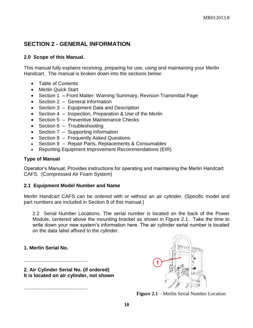
2.2 Serial Number Locations. The serial number is located on the back of the Power Module, centered above the mounting bracket as shown in Figure 2.1. Take the time to write down your new system‟s information here. The air cylinder serial number is located on the data label affixed to the cylinder.
1. Merlin Serial No. _______________________
2. Air Cylinder Serial No. (if ordered) It is located on air cylinder, not shown _______________________ Figure 2.1 – Merlin Serial Number Location

MR012013.8
11
2.3 List Of Abbreviations/Acronyms & Terms Used In This Manual
CAF Compressed Air Foam. Foam created by injecting air into a surfactant-carrying liquid solution such as the many fire fighting foam concentrates/solutions commercially available.
CAFS Compressed Air Foam System. A foam generating system that uses compressed air as a primary energy source.
CFM/SCFM Cubic Feet per Minute/Standard Cubic Feet Per Minute – Alternate unit of measure for volume throughput.
Concentrate A highly concentrated foam solution intended to be combined with water in the Merlin‟s liquid storage tanks.
Dry Foam
„Dry‟ foam is a term used for highly expanded foam. The more air injected into the surfactant solution the greater the foam expansion. Dry foam contains more air and requires less liquid to create.
Expansion Ratio
The ratio of foam volume created after expansion to the liquid volume present before expansion. A 1:1 ratio means the liquid has not been expanded. A 15:1 ratio means the liquid has been expanded to 15 times its original volume.
High-Pressure Air
The Merlin can accept air from one of two sources – a high-pressure air source or an air compressor. The high pressure air cylinder, rated at 4350/4500-PSI is the source of the Merlin‟s high-pressure air supply.
Low-Pressure Air The Merlin can accept air from one of two sources – a high-pressure air source or an air compressor. Air compressors are the source for low-pressure air.
Solution As used in this manual "solution" refers to a either a water + foam concentrate mixture or an undiluted foam solution.
PSI Pounds per Square Inch – Unit of measure for pressure.
Wet Foam „Wet‟ foam is a term used for unexpanded or minimally expanded foam. Wet foam contains less air and requires more liquid to create.

MR012013.8
12
2.4 Purpose of Equipment
The Merlin Handcart CAFS is a multiple use, self-contained foam delivery apparatus specifically designed for rapid, mobile response to fire emergencies and hazmat response missions. The Merlin is capable of creating and applying foam solutions as an independent system, using only on-board resources (liquid and air). The Merlin also has the ability to connect to an external air source (air compressor) in lieu of a high-pressure air cylinder. Utilizing an external air source eliminates the operational limitations imposed by using a limited on-board containerized air supply.
The Merlin is capable of applying numerous foam solutions, including but not limited to Class A& B firefighting foams (including long duration proteins, AFFF and AR-AFFF), decontaminating foams such as EasyDECON® DF200, moldicides and many new wetting agents and combination A/B firefighting agents.
If you are unsure of the suitability of a foam concentrate or it‟s compatibility with the Merlin system, contact Intelagard before using the concentrate in the unit. For additional information on capabilities and employment modes see Sections 3 (Equipment Data and Description) and 4 (Inspection, Preparation & Use of the Merlin) of this manual. 2.5 Safety, Care, and Handling
WARNING! The Merlin Handcart uses high-pressure, containerized air as an energy source to create and propel foam onto a target. Before operation, ALWAYS verify that all hoses and accessories are properly connected. Further, ALWAYS inspect the unit to ensure the integrity of the air cylinder is not compromised and all lines are serviceable.
2.5.1 High Pressure Air. The Merlin system uses a high-pressure air cylinder as the container for air energy that creates and propels foam onto targets. Users MUST ALWAYS exercise appropriate cautions when filling, transporting and using high-pressure air cylinders. The cylinders provided by Intelagard are carbon-fiber wrapped for added safety, and the installed air cylinder valve includes a burst disk. In the event a cylinder is overcharged, the burst disk will rupture at ~6750 psi, venting the air into the atmosphere. Intelagard‟s air cylinders are manufactured to Department of Transportation (DOT) standards, which require a cylinder be capable of withstanding 3.33 times operating pressure without incident (3.33 x 4500 psi). The DOT special permit number is provided on the cylinder label. Always use cylinders that meet DOT standards in the Merlin. The Merlin also has a low pressure port for utilizing power from a compressor. SAFETY must always be foremost in the operators mind to prevent accidents or incidents that could lead to system damage and/or personal injury. Read and observe all safety warnings in this manual and NEVER attempt to operate a Merlin CAF system with an air leak. If escaping air is heard once the system is pressurized, turn off the air supply, activate the handset to release trapped air and fluid and then thoroughly inspect the system to identify the source of the air leak – do not use a Merlin with an air leak!

MR012013.8
13
2.5.2 Hazardous Materials. The Merlin ships with the air cylinder (if purchased) empty; therefore there are no hazardous material restrictions on transport or storage of the Merlin Handcart. Fire foam concentrates are also free of restrictions on transport and storage. Intelagard provides concentrate MSDS‟s on request, and a MSDS is enclosed in all foam concentrate cases. The Merlin is suitable for use with a multitude of foam concentrates therefore it is not possible to address all possible contingencies within this manual. If purchasing Class A or B fire foam concentrates or EasyDECON® DF200 through Intelagard these materials are environmentally safe and also impose no restrictions on transport or storage beyond standard temperature considerations for long-term storage. In the interest of personnel safety and system integrity users must take the time to familiarize themselves with the qualities of the solutions they will apply with the Merlin Handcart by thoroughly reviewing the MSDS provided with the foam concentrates. 2.6 Commercial Warranty Information
Intelagard provides a limited commercial warranty included in the purchase agreement and/or contract. Intelagard‟s commercial warranty is included at the end of this manual, and is available on our webpage, www.intelagard.com.

MR012013.8
14
SECTION 3- EQUIPMENT DATA AND DESCRIPTION
Section 3 Contents:
3.0 Merlin Characteristics, Capabilities and Features
3.1 Merlin Physical Parameters
3.2 Merlin Operational Parameters
3.3 Location of Major Components
3.4 Description of Major Components
3.5 Description of Merlin Controls and Indicators
3.6 Merlin Modes of Operation
3.7 Nozzle Options
3.8 Foam Mixing and Nozzle Guide
3.0 Merlin Characteristics, Capabilities and Features
3.0.1 The Merlin is a self-contained, independently functioning and transportable Compressed Air Foam (CAF) generation apparatus, highly suited for fire and hazardous vapor suppression, liquid spill response, and military and civil decontamination operations. The Merlin is designed to apply foaming solutions for fire suppression (Class A& B), decontamination, hazardous material remediation, biohazard control, toxic material spill remediation, cleaning and mold control, as well as many other applications
3.0.2 The Merlin is capable of applying most commercially available foam concentrates, including Class-A, long-duration protein, AFFF, AR-AFFF, decontaminating foams, and many new wetting agents and combination A/B agents. The Merlin has many additional applications, including application of non-foaming liquid solutions and air-aspirated foam with simple nozzle changes and control adjustments. Contact Intelagard for recommended foaming agents or with any questions regarding system capabilities.
3.0.3 The Merlin is powered by means of air energy, provided by an approved air cylinder or external air compressor2. Filtered, breathing quality air is injected into an approved surfactant solution to create foam, which is propelled onto a target via the air energy that also drives the internal pump subsystem. Intelagard offers DOT-approved 66 cu. ft., 4350/4500-psi, carbon-fiber wrapped air cylinders with the Merlin. If other air cylinders are used in the Merlin, they must meet Intelagard‟s criteria to avoid voiding the system's warranty. See Section 7.3 for air cylinder compatibility information.
WARNING!NEVER use high and low pressure sources to power the system at the same time! Doing so will result in severe damage to system!
2 To operate the Merlin without performance degradation an air compressor must be capable of providing 15-
CFM of filtered air at 100-110 psi. See Section 7. Paragraph 7.1 for additional information

MR012013.8
15
3.1 Merlin Physical Parameters
System Specifications.
COMPLETE SYSTEM: Dry Weight: System: ~80.7 lbs3 (without fluid or air cylinder)
Full Weight: ~224 lbs (with 14 gal fluid and 1 full air cylinder)
Dimensions: ~49.25” H x 19.25” W x 23.75” D (height measurement will change with tire inflation and tire choice)
TANK:
Liquid Capacity: (2) 7 gallon tanks (measured to top of sight tube)
Material: Molded Polypropylene
Closure (Cap): Lanyard retained, vented, poly construction, 3” diameter
PUMP:
Combined Flow: ~10 gallons per minute4 (gpm) liquid flow rating
Pressure: 100 psi Optimum, 110 psi Maximum
Construction: Glass reinforced poly housing with Santoprene internals
AIR INJECTION (Foam Expansion Control):
Adjustable by mechanical valve, 90 degrees rotation, wet/dry setting
COMPRESSED AIR FOAM (CAF) MANIFOLD:
Expansion: 1:1 (liquid application) to ~35:15
Air Consumption: ~9.5 cfm Max6
Resupply Ratio: ~1:1 MAX (14-gal tank load emptied per full air cylinder)7
Output Stream: ~105 gallons per minute finished foam
Output Throw Distance: ~45 ft MAX8
3 Intelagard cylinder adds ~13 lbs.
4 The Merlin pumps are individually rated to dispense ~5-gallons of liquid per minute. When working in
conjunction with the CAF components pump flow is reduced by as much as 35%. 5 Achievable expansion ratio depends on foam solution composition. Concentration and concentrate quality will
affect finished foam expansion. 6 Air consumption varies according to foam solution make-up and wet dry setting. Re-supply ratio based on 66
cu. ft, 4500psi cylinder. 7 The tank to cylinder resupply ratio will vary according to foam solution, nozzle selection and system settings
(wet/dry). 8 Wet/Dry settings, foam product, nozzle used, wind and other factors will significantly affect foam throw
distance.

MR012013.8
16
3.2 Merlin Operational Parameters
OPERATIONS PARAMETERS
Structure, Woodland Fire Fighting
Class-A Foam. Foam expansion ratio should be adjusted via the Air Control Valve to determine the best setting for the situation. See Foam Mixing and Nozzle Guidelines, Section 3.8 for more recommendations.
Vehicle, Tire and Fuel Fires
Class B (AFFF or AR-FFF) foam. Foam expansion ratio should be adjusted via the Air Control Valve to determine the best setting for the situation. See Foam Mixing and Nozzle Guidelines, Section 3.8 for more recommendations,
Decontaminant Solution, EasyDECON® DF200
EasyDECON DF200 is available in a three-part formulation that ships in 5 gal, 100 gal and 500 gal configurations. Add Part 1 to Tank A, Part 2 to Tank B, and finally, Part 3 to Tank A when ready to deploy. (Shelf life of the EasyDECON DF200 is significantly degraded once Part 3 is added to Part 1.) Do not dilute with water. Apply at expansion ratio best suited for the target area and agent challenge. Use the fan spray nozzle to apply foam to vertical surfaces.
Flow / Capacity / Throughput
14 gal (total) fluid tanks can yield up to ~490 gal of finished foam with the Air Control Valve adjustment set fully to the „dry‟ setting using a smoothbore nozzle (~35:1 expansion
9). Foam expansion is a function of the amount of air injected into a liquid
solution. A higher “wet” setting will use more liquid and less air. A higher “dry” setting will use more air, and less liquid. Optimum settings must be determined by the operator based upon the environment, mission and specific challenges presented. As air consumption varies based upon the wet/dry setting, operators can expect to empty the fluid tanks approximately one time on a fully charged air cylinder. If „wetter‟ foam is being applied the air supply will last comparatively longer than when applying „dry‟ foam.
Set-up Times
Tank Refill Time: ~1-2 minutes
Pumping time: Subject to system settings
System PMCS: < 10 minutes
System Start-Up: < 1-2 minutes
System Shutdown: < 1 minute
Configure for external air: < 2 minutes
Foam Projection Distance
Projection distance is a function of wet/dry settings, foaming agent, air source, nozzle used and weather. With standard equipment, projection distance is up to ~45 feet
10
Operating Pressure 100 psi optimal, 110 psi maximum
Low Pressure Air
(Air Compressor) Requirements
Compressor must provide a minimum of 15-scfm at 100 psi optimum, 110 psi maximum. Owner/operators should test their compressor to determine suitability for use with the Merlin
Foam Expansion System: 1:1 (unexpanded) up to ~35:1 (35 times original liquid volume). With Mid-X Nozzle: up to ~ 70:1 is achievable
Accessories See section 9 of this manual
Table 3.2.1 - List of Merlin Operational Parameters
9 Achievable expansion varies based upon concentrate and nozzle used and operator chosen system settings.
10 Throw distance can vary significantly based upon foam concentrate, water quality, wet/dry settings, air quality,
nozzle used and weather.

MR012013.8
17
3.3 Location of Major Components
Figure 3.3.1 - Location of Major Components
ITEM COMPONENT FUNCTION
1 Air Cylinder and Nozzle Pouch
Mold and mildew resistant Cordura® fabric pouch for cylinder storage and nozzle storage
2 Air Cylinder Retention Straps
Retention straps to hold cylinders in place for safe storage and transport
3 Air Cylinder(s) and Valve(s)
4350/4500 psi carbon fiber wrapped, 66 cu. ft. air cylinder; Standard US cylinders are equipped with CGA valves with burst disk (DIN fittings available on request)
4 Portable Handcart Aluminum handcart on 10" pneumatic* tires with extended handle for easier movement. (*solid rubber tires available upon request)
5 Control Panel / Removable Equipment Case
Control panel includes air control valve, flow balancing valves for fluid tanks and cylinder pressure gauge. Equipment case houses functional components of the Merlin, and can be removed for remote operations.
6 Low Pressure Air Connection
Connection for low pressure auxiliary air source
7 High Pressure Air Connection
Connection for high pressure air cylinder. Connects to cylinder with "high pressure whip line"
8 Handset / Hose Assembly
20' x 3/4" ID hose, ships with full port high performance handset attached. Nozzle attaches to handset via quick connect fitting

MR012013.8
18
ITEM COMPONENT FUNCTION
9 Nozzle Nozzles are interchangeable, and used to tailor foam application to the mission – see Section 3 paragraph 3.7 for additional information Merlin ships standard with 12 mm Smooth Bore Nozzle.
10 Discharge Port Port where foam exits Merlin to the attached hose/hose handset assembly connected via quick connect fitting
11 Fluid Tanks (2) Twin 7 gal (measured to top of sight tube) tanks are molded from high grade polypropylene resins. Configured with sight tubes for fluid level monitoring. Includes drain plug for easy cleaning.
12 Fluid Ports and Caps 3" caps covering the Merlin's tank filling ports. Caps are vented and lanyard retained
13 Flow Balancing Valves
Valves adjust fluid flow for individual Merlin fluid tanks
14 Air Control Valve An adjustable dial, labeled Wetter Foam and Dryer Foam. Used to select the amount of air injected into the foam thus controlling the foam expansion ratio.
Table 3.3.1 – Merlin Major Components.
3.4 Description of Major Components
#1. Air Cylinder and Nozzle Pouch: The air cylinder(s) are held in the Merlin cart unit in an attached, padded ballistic cloth pouch and polyethylene sheet. Two standard cylinders can be accommodated at the same time. This allows for efficient recharging of the air supply if the Merlin is being used for extended deployment. The cylinders are placed in the pouch, valve end up, and one cylinder is connected to the system.
#2. Air Cylinder Retention Straps: There are two cylinder retention straps on the handcart cross member directly above the pouch. These straps must be buckled and tightened around the cylinder(s) to ensure secure transport of the cylinders and operator safety.
#3. Air Cylinder(s) and Valve(s) - Intelagard air cylinders are 4350/4500 psi carbon fiber wrapped high pressure air cylinders. Our air cylinders ship with the valve installed (CGA or DIN) and are ready to be filled upon receipt by customer. Our standard cylinders have a DOT or CE label around the cylinder
body and are certified for use only with Intelagard CAF systems. These carbon composite cylinders have a 15-year service life, and must be hydro-statically tested every five years per DOT test criteria. The date of manufacture and the service pressure rating can be found on the DOT label. The valves incorporate a burst disk, designed to rupture at approximately 6750 psi in the event of over-filling. Per DOT regulations high-pressure cylinders are manufactured to withstand overfilling to 3.33 times operating pressure. 4350 cylinders have been manufacturer-approved for filling to 4500psi. Always inspect cylinders for damage prior to re-charging. Cylinders incorporate a serial number on the data plate.
WARNING! To maintain the integrity of the system Intelagard recommends using only quality, filtered air to charge our cylinders. Never use a Merlin air cylinder as a breathing air cylinder! Only persons trained in the proper use of air compressors and cascade systems should refill air cylinders!
Figure 3.4.1 – Air Cylinder

MR012013.8
19
#4. Portable Handcart: The Merlin is mounted to a rugged aluminum handcart that allows the user to comfortably transport the unit, whether full or empty. The standard 10” pneumatic tires are mounted on alloy wheels for movement over uneven terrain. The tire pressure should be maintained at a minimum pressure of 30 psi, with a maximum pressure of 50 psi. The extended aluminum handle allows for proper balancing of the system while transporting. Custom bracketing has been designed to allow for secure connection of the tanks, cylinder pouches and equipment modules. Optional semi-pneumatic and hard rubber tires, as well as larger tires and wheels are available from Intelagard.
#5. Control Panel / Removable Equipment Case:The control panel located on the front of the removable equipment case is configured for effective use by personnel in Personal Protective Equipment (PPE). The controls on the panel include the air control valve (for wetter and drier foam expansion consistency), the flow balancing valves for Tank A and Tank B, and the cylinder pressure gauge.
The equipment case can be easily and quickly removed from the Merlin by detaching the four quick connect fittings located on the back of the case, and removing the pins holding the case and bracket to the handcart. Once removed, the case can be carried to remote locations and connected to a high or low pressure air source, and to bulk fluid storage (via optional fluid drafting hoses) for large scale operations. The case houses the functional components of the Merlin system including various calibrations and adjustments that require special equipment and procedures to change. These settings are factory preset.
WARNING! Opening this enclosure improperly may lead to injury, death or equipment damage!
The equipment case may only be opened and serviced by factory authorized personnel. Breakage of the factory seal by unauthorized personnel will void equipment warranty!
#6. Low Pressure Air Connection: Merlin users with an available compressed gas supply (nitrogen or compressed air) can operate the Merlin system by bypassing the internal regulation system and supplying regulated low pressure directly to the Merlin via the equipment case low pressure air connector. A compressed gas supply regulated to 110psi MAX can be connected via the quick-disconnect fitting. An external compressor must provide a minimum of 15-scfm at 100 psi optimum, 110 psi maximum. Owner/operators should test their compressor to determine suitability for use with
the Merlin.
#7. High Pressure Air Connection: Below the low pressure connection is a male quick-disconnect for high pressure connection to the equipment case. Cascade cylinder systems
Fig.3.4.2 High and Low Pressure Air Connections

MR012013.8
20
Fig 3.4.3 High performance handset
Fig 3.4.4 Trigger Handset
and SCBA type cylinders can be connected here by using the high pressure whip line included with the Merlin system. The high and low pressure connections are gender-alternated and different in connection shape. They are not interchangeable. One end of the high pressure whip line connects to the equipment case and the other connects to the cylinder valve.
#8. Handset and Hose Assembly: The Merlin ships with a standard 20‟ long x 3/4” diameter hose and high performance handset assembly. The handset comes pre-installed on the hose. The system connection end of the hose is equipped with a quick-connect coupling to make connection to the discharge port quick and easy. The tip of the handset incorporates a quick-connect coupling for multiple available nozzles.
The discharge hose has a high degree of chemical compatibility. The discharge hose is rated for up to 300 psi (20.7 bar) of pressure. The hose also has a flame resistant outer jacket. Owners/operators should adhere to the guidelines set forth in NFPA 1962 “Standard for the Inspection, Care and Use of Fire Hose, Couplings, Nozzles and the Service Testing of Fire Hose”.
8.1 High performance handset Configuration - Standard): The high performance handset ships standard with the Merlin, and is connected to the 20‟ hose with a stainless steel quick-connect fitting. Once the unit is filled with foam solution and the air cylinder is secured in place and opened, all that is required to operate the system is to safely aim the handset and open the valve by turning clockwise to stop. This
handset requires two hands to operate. One hand firmly grasps the pistol grip handle at the base of the valve, while the other hand rotates the valve handle counterclockwise (forward) to turn on and clockwise (upward) to turn off. The system will dispense foam as long as the valve is open, and will cease when the valve is closed, or when components are exhausted.
8.2 Trigger Handset (Optional):The trigger handset is a rapid-action valve that is operable by one hand. It consists of a handset trigger valve that is operated by squeezing the trigger with the index finger. This handset trigger has a locking tab (dependent upon order specifications) that allows the user to lock the handset in the open position by pressing the top
portion of the trigger. To disengage the lock, squeeze in and down on the top section of the trigger, allowing the lock tab to release. Use of this handset with the Merlin will result in reduced throw distance, but is recommended for use with decontaminant solutions such as EasyDECON DF200. Call Intelagard or your local distributor for more information.
The handset hose attaches to the discharge port on the Merlin with a stainless steel quick-connect fitting. When not in use, the hose should be stored by coiling it around the metal hose bracket located on the front of the fluid tanks.
CAUTION! NEVER pull the Merlin using the hose!

MR012013.8
21
#9. Nozzle: Both the standard high performance and optional trigger handset are equipped with a quick-connect fitting for easy exchange of the nozzle. Nozzle changes allow the operator to tailor the fluid application to best suit the current mission. See Section 3 paragraph 3.7 for additional nozzle options.
#10. Discharge Port: The discharge port is located at the bottom on the front of the Merlin, between the two fluid tanks. This is where fluid is discharged from the unit. The hose attaches here via a stainless steel quick-connect fitting.
#11. Fluid Tanks: The two 7-gal. (measured to the top of the sight tube) Merlin fluid tanks are molded from high grade polypropylene. The tanks are configured with front mounted sight tubes for easy monitoring of fluid levels. A drain plug is located on the bottom of each tank for easy cleaning. Clear plastic plates are located on each tank for use by the operator for identification of agent and tank fill date.
#12. Fluid Ports and Caps: The 3-inch (7.6 cm) fluid fill ports and threaded caps are located at the top of the fluid tanks. The caps are removed from the tanks by turning counterclockwise, and are held in place once removed by a stainless steel lanyard. The caps are vented to allow for off-gassing of agents being used.
#13. Flow Balancing Valves: Twin flow valves are located on the control panel. The valves are calibrated from 0% (closed) to 100% (open). Normal flows at 100% operation will be between 4.5 to 5 gpm (17.034 and 18.927 lpm), per valve. Valves are designed to hold at given settings, and regulate the volume of fluid discharged from each tank.
#14. Air Control Valve: The air control valve is located on the front face of the equipment case. This valve controls the wetness of the discharged foam. The valve handle turns 90 degrees, from the wet foam setting (horizontal) to the dry foam setting (vertical). A directional label is included at the valve handle.

MR012013.8
22
3.5 Description of Merlin Controls and Indicators
The Merlin has simple operator controls and indicators, all of which are explained in this section.
ITEM COMPONENT FUNCTION
1 Air Cylinder Air On/Off Knob
Used to turn airflow from the cylinder On or Off. Once connected to the HP fittings and turned on, the system is energized – ALWAYS point the discharge nozzle in a safe direction! To turn the air ON turn the knob counter-clockwise SLOWLY to stop. To turn the air OFF turn knob clockwise to stop. (This air valve knob may be a "push to turn", depending on configuration.)
2 Air Cylinder Pressure Display (CGA Valves Only)
Displays the amount of air in the air cylinder
3 Low Pressure Air Connection Connection for low pressure auxiliary air source. Connects via quick-connect fitting
4 High Pressure Air Connection Connection for high pressure air cylinder. Connects to cylinder with "high pressure whip line"
5 Handset / Hose Assembly 20' x 3/4"diameter hose, ships with full port high performance handset attached. Nozzle attaches to handset via quick-connect fitting
Figure 3.5.1-Merlin Controls & Indicators

MR012013.8
23
ITEM COMPONENT FUNCTION
6 Pressure Gauge High pressure gauge build into the control panel. Dual scale, liquid filled gauge that indicates cylinder fill pressure.
7 Air Control Valve An adjustable dial, labeled “Wetter Foam” and “Dryer Foam”. Used to select the amount of air injected into the fluid thus controlling the foam expansion ratio.
8 Flow Balancing Valves Valves adjust fluid flow for individual Merlin fluid tanks
9 Discharge Port Port where foam exits Merlin to the attached hose/hose handset assembly connected via quick connect fitting
Table 3.5.1- Merlin Controls & Indicators
3.6 Merlin Modes of Operation
The Merlin is capable of being used in two different configurations. Using optional nozzles, the operator can tailor system capabilities to specific missions /challenges.
3.6.1Standard Configuration: Self-Contained, High-Pressure Air Cylinder. In this mode the Merlin uses on-board consumable supplies, including water, foam concentrate and high-pressure containerized air to create and propel foam onto a target. Using a high-pressure cylinder charged with 4500psi of air, the Merlin injects air into a concentrate solution to create foam, which may be unexpanded (1:1) or fully expanded (up to ~35:1). The Merlin has an air control valve located on the control panel located on the equipment case that allows for the selection of a desired foam expansion ratio. Air and fluids are combined in the Merlin to create foam, which is then expelled from the nozzle when the operator activates the handset. Operator settings will affect the consumption rate of the air and liquid solutions. At 1:1 (unexpanded) the air tank can empty the fluid tanks up to ~three (3) times before the air cylinder is emptied. At full expansion (~35:1 using the smoothbore nozzle) the air cylinder will empty the fluid tanks ~1 – 1.5 times before the air supply is exhausted. Operations with an air cylinder are covered in Section 4 paragraph 3. 3.6.2 Alternate Configuration: External Air Source (Compressor). The Merlin can be powered by an external, low-pressure air supply in lieu of the high-pressure air cylinder. For large, sustained missions or fixed-site protection, containerized air may be impractical or less desirable. Air compressors that are capable of providing 15 SCFM of filtered air at 100 to 110 psi can be connected to the Merlin with a standard air line, thus eliminating the requirement for air cylinders. The equipment case can be removed for remote operations using the low-pressure air supply (compressor). Note that compressors operate off a stored air supply and that under-rated compressors will degrade Merlin performance. Powering the Merlin with low-pressure air requires the purchase of an optional air supply line available in lengths up to 100 feet (See Section 9 paragraph 9.3). See Section 7 paragraph 7.1 for additional information on using an air compressor for air energy in lieu of a high-pressure air cylinder.

MR012013.8
24
3.7 Nozzle Options
3.7.1 Smoothbore Nozzle, 12mm. The Merlin ships with a 12mm smoothbore nozzle, which is a general purpose nozzle. With this nozzle the operator has the ability to project foam (also known as the “throw distance”) up to ~45-feet. Throw distance varies based on nozzle selection, foam expansion setting, concentrate qualities, air source and weather conditions, principally wind and precipitation. Generally the operator uses the smoothbore for initial attack of a fire, reducing fire to a point where the operator can safely approach to conduct mop-up operations. The smoothbore may be used effectively for 1:1 up to ~35:1 expansion applications. At 1:1 (unexpanded) the operator consumes ~ 3 fills of the 2 fluid storage tank fills per one air cylinder with this nozzle. At full expansion (~35:1) the operator consumes 1-1.5 storage tank fills per one air cylinder.
3.7.2 Fan Spray Nozzle (Optional Item). The fan spray nozzle is best suited for applying a thin, uniform layer of foam, making it ideal for covering large surfaces with minimum splash-back and waste. Based on the expansion ratio adjustment, the projected foam can adhere to walls and ceilings, and the application pattern is well suited for covering floors and terrain. When held waist high and passed slowly over the target surface the fan spray will lay down a very uniform layer of foam approximately 3-feet in width. The fan spray nozzle may be used effectively for applying foam at 1:1 up to ~15:1 expansion ratios. Air consumption will be similar to that of the smoothbore and dependent on the selected expansion ratio.
3.7.3 Mid-X Nozzle (Optional Item). The Mid-X nozzle is an air aspirating nozzle that introduces additional air into the foam product at the nozzle, making expansion ratios of up to ~70:1 achievable. THE MID-X NOZZLE SHOULD BE USED ONLY AT THE "WETTER" SETTING ON THE AIR CONTROL VALVE. The foam dispensed is a very thick layer of foam, meant to saturate the target area. This foam blanket serves to smother (thus

MR012013.8
25
preventing reignition) and to trap vapors (preventing off-gassing of potentially harmful materials). At full expansion, the operator can expect to deplete a full air cylinder after ~3 tanks of liquid. The Mid-X nozzle is well suited for mop up operations after a fire is reduced.
3.7.4 Piercing Tip Nozzle (Optional Item) The piercing tip nozzle is a stainless steel smoothbore nozzle intended to be used to force foam into an enclosed space such as a room, vehicle interior or engine compartment, either by breaching with the tip of the nozzle or by inserting the tip through an existing gap. This allows the operator to attack a fire without direct exposure to its source. Once a fire has been sufficiently reduced the operator can then switch to one of the other nozzles to completely extinguish the fire. The piercing tip nozzle has a maximum throw distance of ~20 feet. For planning purposes operators should plan ~1-1.5 tanks of fluid to a single air cylinder.
CAUTION! DO NOT grip the plastic handset when piercing an object – it will break! Hold the nozzle handgrips to thrust the tip through the object.
3.7.5 Hazmat Nozzle (Optional Item). The Hazmat Nozzle is designed to dispense non-foaming agents, although EasyDECON DF200 can also be deployed using this nozzle. The Hazmat nozzle orifice is fully adjustable from a straight stream to a wide cone spray. The flow rate of the nozzle also changes as the pattern is adjusted. The Air Control Valve should be in the “Wetter Foam” position when using this nozzle.

MR012013.8
26
3.8 Foam Mixing and Nozzle Guide
Mixing measurements per single 7 gal. (26.5 L) tank (Measured to top of sight tube.)
Nozzle Key: 1=Smooth Bore, 2=Fan Spray, 3=Mid X, 4= Piercing Tip, 5=Hazmat
WARNING! Thoroughly flush system with water prior to switching from one type of solution to another.
Foam Type % Mix Mix Ratio (min.)
Pre-Mixing
Nozzles
Class A
1%
9 oz / 7 gal (26 cl / 26.5L)
No 1,2,3,4
Protein
3%
28 oz / 7 gal (83 cl / 26.5 L)
Yes 1,4
Protein
6% 54 oz / 7 gal
(1.6 L / 26.5 L)
AFFF
AR-AFFF
3% 28 oz / 7 gal
(83 cl / 26.5 L)
Yes 1,2,3,4
AFFF AR-AFFF
6% 54 oz / 7 gal.
(1.6 L / 26.5 L)
Non-Foaming
Agents
Per Manufacturer's Instructions 5
EasyDECON®
DF200 Crystal Clean®
100% Full Strength Yes 1,2,3,4,5
Refer to formula manufacturer's mixing recommendations whenever possible.

MR012013.8
27
SECTION 4 – INSPECTION, PREPARATION & USE OF THE MERLIN
4.0 General
Section 4 describes operator procedures for initial receipt, inspection, preparation for use and operation of a Merlin. This section is divided into subsections, as detailed below:
4.1 Uncrating
4.2 Inventory & Inspect –Standard Equipment Shipped with the Merlin
4.3 Prepare for Use – Configure the Merlin for Operation
4.4 Operating the Merlin Handcart
4.5 Drafting
4.6 Considerations for Spray Operations
4.7 Refilling Operations
4.8 System Shut-Down
4.9 System Venting Procedure
4.10 Storage Options
4.11 Freeze Protecting the Merlin
4.1 Uncrating
Uncrate your system - inventory and inspect all items. The contents of your crate will be dictated by your agreement at the time of purchase – check your purchase agreement to determine if all items are present at the time of uncrating!
Your Merlin and purchased accessories are shipped in a durable, re-sealable wooden crate that should be retained for repacking the Merlin for storage or shipping. The wooden crate serves to secure the unit and components during transport, preventing damage, while also serving to protect the contents from the environment. The top of the crate is secured with metal quick disconnect clips that are easily removed with a screw driver. Retain the clips for re-use.
After unpacking the contents of the crate it is prudent to immediately inventory and inspect the contents. If any defects are noted, such as missing components or transport damage, immediately contact the distributor from whom you purchased the system to file a claim for action/corrective action.

MR012013.8
28
4.2 Inventory& Inspect - Standard Equipment Shipped with the Merlin
After opening the crate locate the packing slip and immediately inventory the crate contents. Table 4.2.1 provides a detailed listing of the items shipped standard with the Merlin – contents may vary based upon your purchase agreement.
Quantity,
Nomenclature, Description Action
1 each, Merlin
Handcart ( may
have been ordered
with or without air
cylinder)
Merlin Handcart
Inspect the fluid tanks for cracks and obvious damage.
Verify that the two (2) 3” storage tank caps are present and the threads
are undamaged. Unscrew the caps and verify the lanyards are
attached. Replace caps.
Note the Merlin serial number, which is provided on the back side of
the Equipment Case above the bracket. Record the serial number for
future reference/accountability.
Note the presence and condition of the Air Control Valve, Flow
Balancing Valves, and the Low- and High-Pressure Air Connections
on the Equipment Case.
1 each, Carbon-
Fiber Wrapped Air
Cylinder (if
purchased)
Comes with CGA valve
pre-installed, standard.
DIN valves are optional
NOTE: Cylinders are
normally shipped empty.
Before operations, fully
charge the cylinder to
4500psi. Military
contracts may require
cylinders to ship full –
check the pressure gauge
on the valve (CGA only) to
determine fill status.
Inspect the cylinder for any obvious damage.
Obvious damage to the cylinder means that the cylinder should be
inspected by a certified official before use.
For CGA-valve equipped cylinders – verify the pressure gauge is
intact.
Rub marks are routine wear and are not cause for concern.
Note and record the cylinder serial number, present on the cylinder
data plate
1 each,
Handset/Hose
Assembly
20’x3/4” discharge hose
tipped with high
performance handset
Inspect hose for cuts, tears cracks. Inspect the on/off valve on the
handset and the quick-connect fitting on the hose.
1 each, 12 mm
Smooth bore nozzle General purpose nozzle
Ships attached to the handset with a brass quick-connect coupling.
Remove the nozzle from the handset and reinstall to verify attaching
hardware functions properly
Long Neck Funnel Funnel For use when filling Fluid Tanks to minimize aeration of foam solution
Foam concentrate
containers
Container(s) of foam
concentrate
Containers of foam concentrate included with system for training,
testing or mission use. (Quantity, volume and type designated by
customer specification)
Valve Connection
O-ring (2) extra O-rings Replacement O-rings for CGA or DIN connection
Table 4.2.1. Standard Equipment Shipped with the Merlin

MR012013.8
29
4.3 Prepare for Use – Configure the Merlin for Operation
NOTE: Prior to first use of the Merlin system it will be necessary to have the air cylinder charged by authorized personnel. Note the pressure gauge on the air cylinder valve (CGA valves only). The pressure gauge will read zero (0-psi) on an empty air cylinder. When cylinders with DIN valves are attached to the Merlin, cylinder pressure can be read on the Pressure Gauge located on the Merlin Control Panel.
CAUTION! ALWAYS secure cylinders during transport. ALWAYS ensure your cylinders are charged with filtered, breathable, not industrial, air. See Section 7 paragraph 7.2 for additional information on cylinder charging.
4.3.1 Install and Connect Charged Air Cylinder. Place the cylinder in the air cylinder pouch located on the back of the Merlin with valve facing up. The cylinder should rest securely in the pouch. Connect the plastic buckle on the cylinder retention strap. Pull on the end of the strap to tighten the strap securely around the neck of the cylinder. Ensure that the valve O-ring is in place on the connector. Mate the connector to the cylinder threads - watch for cross threading! Thread the CGA (Din fittings optional) fitting onto the valve threads and hand tighten. See Figure 4.3.1 below. Tighten the connection hand tight, until it is snug. DO NOT turn the air cylinder on at this time!
Figure 4.3.1.1 CGA to Air Cylinder Connection
WARNING! Air cylinders are under high-pressure and must be treated with respect and caution! NEVER attempt to use the Merlin until you have taken the time to review the Warnings and Cautions in this manual – read the manual completely
4.3.2 Fill the Fluid Tanks. With your Merlin fully assembled and fitted with a filled air cylinder installed and connected to the high-pressure CGA fitting, it is now time to pour a fill of foam solution into the Merlin. See Foam Mixing and Nozzle Guidelines, Section 3 paragraph 3.8 for general mixing guidelines. (Refer to formula manufacturer’s recommendations whenever possible.)
The best way to transfer the mixed foam solution into the Merlin fluid tank is with the included long-necked funnel, which minimizes the aeration of the foam solution as it is poured into the Merlin. Fill the foam tank to the desired level, and tighten the fill cap back in place. With Class A foams and some AFFF agents, you can fill the tank with the required amount of water and then gently add the concentrate. This will allow the concentrate to mix properly while minimizing foam expansion in the tank. Always refer to manufacturer‟s directions for proper mixing and usage procedures.

MR012013.8
30
When using EasyDECON DF200 decontamination formula, pour Part 1 into Tank A and Part 2 into Tank B. Add Part 3 to Tank A when ready to deploy the system. Once Part 3 is added to Part 1, the shelf life of the EasyDECON DF200 is 6-8 hours.
4.3.3 Connecting the Equipment Case to the Handcart. If the equipment case is not connected to the Merlin, follow the instructions below. There are 6 connecting points where the Merlin‟s equipment case interfaces with the handcart. See Figure 4.3.3.1.
1. Tilting the case forward, hook the lower end of the equipment case bracket onto the two 3/8-inch diameter pins protruding out from the sides of the handcart. Pivot the case into the upright position until the lock-pin holes align. Insert the lock-pins.
2. Connect the foam exit line to the port labeled “Foam Out” 3. Ensure that Tank A and Tank B lines are connected to equipment case
Figure 4.3.3.1 Equipment Case Connections
4.3.4 Connecting the Handset/Hose Assembly and Nozzle. The Merlin handset and nozzle attaches with a quick-disconnect fitting. This connector is attached by pulling the sliding collar away from the open end. While pulling back on this collar, slide the female connector over the male nipple until it stops. As you release the sliding collar it should pop forward under spring force. Pull lightly on the handset hose to ensure that the connector halves have engaged each other and are locked together. The nozzle connection operates in the same fashion. Pull back on the sliding collar, insert the male connecting end of the nozzle into the handset and release the collar. Pull lightly on the nozzle to ensure that the connection is seated. Nozzles can be interchanged when the system is pressurized however handset hoses cannot!
WARNING! NEVER attempt to disconnect a handset or hose from the Merlin while the cylinder valve(s) is open or the system is pressurized. Always ensure that the cylinder valve is closed and then relieve system pressure by squeezing the handset valve before disconnecting a hose or handset!
WARNING! Before turning the air supply on ensure the handset hose is correctly attached to the Merlin‟s discharge port. Also verify that the handset is NOT in the OPEN position. Pressurizing the system with the handset OPEN will result in foam discharge as soon as the air is turned on!

MR012013.8
31
The Merlin is now ready for operation.
CAUTION! It IS NOT recommended to turn the air supply on and then leave the Merlin dormant. Leave the air off until system use is imminent.
NOTE: The fluid tanks are not pressurized. Once the air is turned on the interior plumbing of the Merlin is pressurized, not the fluid tanks. This design allows operators to open the fluid tanks to replenish the Merlin‟s fluid supply „on the fly‟.
NOTE: Based upon your operational requirements you may leave the Merlin in this „ready for use‟ state (full of fluid) for a period of up to 6 months without concern (Class A and AFFF foam concentrates only). As the Merlin is an emergency response, fluid pumping system, the system should be inspected and tested every 30 days when in this ready state. Operators should fill out the plastic data plates on the fluid tanks to annotate the type of concentrate fill and the date the concentrate was mixed.
CAUTION! If storing the Merlin outside and under conditions where temperatures may reach freezing, your system could sustain freeze damage if appropriate steps are not taken. For cold weather considerations see Section 4, paragraph 4.11.
CAUTION: When preparing to use a Merlin system that has been filled with solution and left ALWAYS perform this additional step before attacking a fire. Tilt the Merlin back on the handcart wheels and move it forward and backward vigorously 6-7 times. Performing this step helps to ensure that the concentrate is dispersed within the water. Failure to perform this step could have a direct impact on the quality of the foam produced! .
WARNING! Once the air cylinder knob (or alternative air source) is turned on the plumbing and discharge system is pressurized! It is very important that operators inspect all couplings and attachments before pressurizing the system to avoid system damage and possible injury to personnel.
WARNING! ALWAYS treat the Merlin as though it is pressurized – if unsure point the nozzle in a safe direction and activate the handset. If foam discharges verify the air supply is turned off. If the air is turned off yet the system still discharges a small volume of foam this means the trapped pressure was not released from the system after the air supply was turned off – this is a very important procedural step.
4.4 Operating the Merlin Handcart
4.4.1 Handset and Nozzle Operation. The Merlin high performance handset is a two-handed handset operation. Pay attention to the direction this handset is pointed any time the system is charged. To open the handset valve, turn the valve counterclockwise to

MR012013.8
32
a horizontal position. The handset is now activated. To close the handset, turn the valve clockwise (upward) to stop. See Figure 4.4.1 below.
To change nozzles, pull back on the sliding quick-disconnect collar and pull the nozzle from the fitting. To attach the replacement nozzle, pull back on the sliding collar, fully insert the new nozzles male quick-connect fitting and release the collar, making sure that the collar engages fully and returns to its fully locked position.
4.4.2 Air Control Setting. Operators will, through training and regular use, become familiar with the qualities and virtues of expanded foams versus unexpanded liquids. The air control valve located on the control panel of the Merlin is used to control the amount of air injected into the concentrate solution, therefore the expansion of the foam. Every mission is unique, so there is no one single setting that will be optimum.
Using the air control valve the operator can adjust the foam expansion ratio on the fly while performing spray operations. The Merlin will expand liquid concentrates between 1 and to up to ~35 times their original (unexpanded) volume by adjusting the air control valve. With the optional Mid-X nozzle, which is an air aspirating nozzle, expansion ratios of up to ~70:1 are achievable and the air control valve should be in the “Wetter Foam” position.
Turning the valve to the full „Wetter Foam‟ setting will result in minimal expansion of the concentrate. At full „wet‟, the system will dispense a watery solution with traces of concentrate visible in the stream. The „wetter‟ the setting, the faster the on-board liquid resources are exhausted and the longer the air supply will last. This setting is useful for cleaning and flushing the fluid tank and pump after use, and for emptying the fluid tanks while conserving air resources. Also, the „Wetter Foam‟ setting is used with the optional Mid-X nozzle and optional adjustable Hazmat nozzle for use with non-expanding liquid agents.
Turning the air control valve to the „Dryer Foam‟ setting will inject more air into the solution stream thus creating highly expanded (up to ~35:1) foam. In this state the foam produced will have a consistency similar to shaving cream. A dry foam setting consumes air faster but uses less fluid from the fluid tanks.
During initial training operators should adjust the air control setting to observe and become familiar with usage of this valve to achieve the desired foam quality. Different types of foam concentrates vary in their finished foam qualities. Also, solution viscosities will affect how much air is required to produce the desired finished foam results. Differences in nozzle shapes also effect the air injection requirement and spray patterns.
4.4.3 Flow Balancing Valve Settings. These valves control the amount of fluid coming out of each fluid tank. The Merlin can dispense from either Tank A or Tank B separately or simultaneously. For instance, it is possible to have Class A foam solution in Tank A and Class B foam solution in Tank B to allow for instantaneous response to multiple fire types. Alternatively, multipart decontamination foams such as EasyDECON DF200 can
Figure 4.4.1 High performance handset Operation

MR012013.8
33
be mixed by placing different parts in each tank and then drawing from both tanks at the same time. Operators will, through training and regular use, become familiar with the qualities and virtues of specific foam concentrates, their uses and the Flow Balancing Valve adjustments required for optimal usage.
Perform the following steps to apply foam with the readied Merlin:
STEP 1. Turn the air supply on by slowly turning the air cylinder knob counter-clockwise to stop. When the air is turned on you will hear the pump „chug‟ briefly as air enters the lines. At this time listen for a „hissing‟ indicating a possible leak at a connection. If escaping air is heard immediately turn the air off, bleed the pressure from the system by activating the handset and then trouble shoot the system.
STEP 2. Secure the nozzle to the handset, point it in a safe direction, and activate the handset briefly to charge the system – you will hear the pump cycle.
If necessary make adjustments to the air control valve setting to control the foam expansion to your desired consistency.
The Merlin is now charged and capable of producing foam on demand by activating the handset.
4.4.4 Alternative Powering Option. For remote and/or long term operation, the Merlin can be powered by a standard air compressor of up to 100 psi optimal, 110 psi maximum operating pressure, with a minimum 15 scfm output. The removable equipment case is equipped with a low pressure air supply connector located just above the primary high pressure quick-connect fitting on the back of the equipment case. Contact Intelagard for availability and pricing information on optional low pressure air supply hoses.
To operate from a compressor, ensure the air cylinder knob is turned off and the system has been depressurized – then release the high pressure quick-connect fitting that attaches the air cylinder hose to the back of the equipment case. Insert a standard ¼” air male quick connect fitting into the female low pressure air fitting. See Section 7 paragraph 7.1 for more information.

MR012013.8
34
4.5 Drafting
In addition to being an independent, stand-alone unit, the Merlin can draft from remote fluid sources by disconnecting the quick-connect fitting(s) on the rear of the equipment case and connecting optional drafting hose(s). The optional drafting hose is 20 ft. (6.1m) in length and can draft from alternative fluid sources such as pails, drums, totes or other large containers. The Merlin equipment case can be entirely disconnected from the cart unit for total remote operation when connected to alternative air and fluid supplies.
The case is removed by disconnecting all quick-connect fittings located on the back of the case (two fluid hoses, one air supply hose, the handset hose and the pressure vent tube), and removing the two ring pins that hold the case bracket to the handcart. Follow these steps to convert to stand alone operations:
STEP 1. Release the two “Fluid In” quick connect fittings located on the back of the equipment case.
STEP 2. Insert draft hose(s) with male quick connect fittings into female quick connect fittings on the rear of the case.
STEP 3. Position the other end of the draft hose(s) into the fluid source(s), making sure that the end remains in the fluid.
STEP 4. Operate the system as noted above. (It will take longer for the pumps to self-prime.)
STEP 5. Remember that the fluid balancing valves on the control panel must be set to correspond with the draft hose(s) in use. If drafting with a single hose connected to Side “A” only, the Side “A” control valve must be fully open (100%) and the Side “B” valve fully closed (0%) for proper operation and reverse for Side “B” only. If using two drafting hoses, normal control operation as previously described will apply.
STEP 6. To draft directly from larger bulk storage containers such as caged totes, draft hoses can be configured to plumb directly to container. Contact Intelagard for more information.
4.6 Refilling Operations
4.7.1 Fluid Depletion/Refill Operations. When the Merlin fluid tank(s) in use is nearly empty foam stream quality degrades noticeably indicated by irregular/intermittent foam discharge and „sputtering‟. If the fluid tank is completely empty the pump will cycle (chug) until the air is turned off. Retreat to a safe area and replenish the fluid in the Merlin. To refill the Merlin‟s fluid tank perform the following procedures:
STEP 1. Remove the tank cap for refilling operations. The fluid in the Merlin tanks is never under pressure – there is no need to turn off the air supply at this time unless the air cylinder will be exchanged.
STEP 2. Add water and/or formula according to the formula manufacturer‟s directions, filling tank to the desired level. NOTE: There may be residual concentrate remaining in the tank that will foam during the refill operation – the faster fluid is added (the greater the fluid

MR012013.8
35
turbulence) the more this will occur. This is a harmless effect of adding fluid into a tank with residual concentrate in it. Operators should wipe away the foam that emerges from the filler neck and continue to fill the unit until it is full.
STEP 3. Add the appropriate foam concentrate – for formulas requiring water, ALWAYS add concentrate to water- never water to concentrate. Replace the liquid storage tank cap. Tilt the Merlin back on the handcart wheels and move the unit back and forth vigorously 6-7 times to mix the tank contents.
STEP 4. Check the pressure gauge on the control panel (or on the cylinder itself if it is a CGA cylinder) to determine how much air remains in the cylinder. If necessary exchange the air cylinder using procedures noted in 4.7.2, below.
STEP 5. If air supply is adequate, continue the operation.
4.7.2 Air Depletion/Cylinder Exchange. During operations, periodically check the pressure gauge on the control panel to monitor the amount of air remaining in the cylinder.
STEP 1. Retreat to a safe area.
STEP 2. Turn the air supply („On/Off‟ knob) to the „Off‟ position by rotating the knob on the cylinder valve clockwise (pushing in on the knob while turning may be required for some models). This turns the air supply off.
CAUTION! The system has air trapped in the lines – after turning the air supply off ALWAYS point the nozzle in a safe direction and activate the handset to release the trapped air and fluid.
STEP 3. Depressurize the plumbing and hose/handset assembly by pointing the nozzle in a safe direction and activating the handset trigger.
WARNING! If the high-pressure connection does not turn easily the air is likely not turned off, or not turned off fully! Make sure the air supply is turned completely off and repeat Step 3 to release the trapped air by activating the handset. Disconnecting the cylinder with the air on will result in a very energetic discharge of air – injury could result and the high-pressure connection O-ring will be blown out. See figure 5.0.1 for O-ring location.
STEP 4. Detach the air cylinder by unscrewing the high-pressure connection – as this connection is hand tight it should unscrew very easily – remember, it was tightened only until snug – if resistance to detaching seems too high the system is likely still pressurized! In this case, depressurize the system by following directions given above. Unsnap the cylinder retention strap.
STEP 5. Exchange the air cylinder. Snap the cylinder retention strap around the neck of the cylinder. Connect the high-pressure fitting to the air cylinder. If the O-ring is compromised, replace it.

MR012013.8
36
CAUTION! If using the trigger handset with the Merlin, ALWAYS ensure the handset trigger is not locked in the down/on position before turning on the system‟s air supply.
STEP 6. Slowly pressurize the system by turning the air cylinder knob counter-clockwise. Listen for pressure entering the system – also listen carefully for any „hiss‟ of escaping air that may indicate an air leak. If there are no air leaks, check fluid levels and continue the mission. If air can be heard escaping from the system immediately turn the air off, activate the handset to release trapped pressure and trouble shoot.
4.7 System Shut Down
The Merlin is powered by compressed air. ALWAYS purge residual pressure stored within the pumping/plumbing systems after use, and before any maintenance procedure.
STEP 1. Turn off the air supply by turning the ON/OFF knob on the cylinder valve clockwise to the full stop position. Some cylinder valves may require a push-to-turn step on the knob.
STEP 2. Open Fluid Balancing Valves on both Tank A and Tank B.
STEP 3. Purge the system of any trapped air by pointing the handset in a safe direction and opening the handset. Do this until all air has been relieved from the lines.
STEP 4. If the system is to be stored during cold temperatures (near freezing and below) the fluid tanks must be drained and filled with winterizing solution or freeze-proof, fire foam concentrate. See Section 4 paragraph 4.11 for additional information.
STEP 5. Check the air remaining in the air cylinder by observing the cylinder air pressure display. If the cylinder is to be removed for recharging, disconnect the high-pressure whip line and remove the cylinder.
STEP 6. It is important to clean your Merlin and store it properly after each use. The components used in the manufacture of this unit are durable, dependable and not susceptible to damage from exposure to approved, quality foam agents. However, it is a good idea to clean and flush your system thoroughly after each use to assure that no residual agents will, over time, clog or otherwise affect the performance of your Merlin.
STEP 7. If the system is to be stored for a long period of time or a different liquid solution is to be used for the next operation, flush each tank by running a minimum of two gallons of clean water to purge each tank and plumbing pathways of any remaining concentrate residues. This prevents trapped concentrates from clogging the plumbing pathway. Turn off the air supply and depressurize the system by activating the handset.
It is now safe to change foam types, cylinders, change handsets/nozzles, and perform all PMCS checks. This operation should be performed at the completion of each use.

MR012013.8
37
4.8 System Venting Procedure
CAUTION! The use of peroxide-based decontamination foam solutions (such as DF200) may result in off-gassing and an internal buildup of pressure within the Merlin. Hot weather conditions will aggravate this condition. The Merlin is equipped with an automatic venting system to avoid any potential damage. The release valve may vent excess pressure at any time the system contains decontamination solution. Please observe and follow all cautions and instructions displayed on the Merlin!
The automatic venting system is located on the rear of the Merlin equipment case. The vent exits into a drain tube that allows any vented material to vent safely away from the equipment and the operator. This device is set at a safe level in order to allow any build-up of pressure to release if necessary.
To remove the vent tube (as you would when disconnecting the equipment case), grasp the small release ring on the exit fitting and depress it toward the fitting, while at the same time pulling the tube away from the fitting. The tube should release with a minimal amount of effort. To reverse the process, simply insert the tube in the fitting outlet and push the tube until it seats fully. Keep the vent fitting pointed towards the ground or in a safe direction at all times.
4.9 Storage Options
4.9.1 Storage in a Ready State. The Merlin can be stored full of fluid and Class A or AFFF foam concentrates (not AR-AFFF) so long as the unit is protected from freezing. The fluid in the Merlin may freeze at or about 32 degrees Fahrenheit. If freezing temperatures are likely but there is a need to maintain the Merlin in a ready state, use freeze-protected foam concentrate from one of many concentrate manufacturers. Under nonfreezing conditions, the Merlin can be stored with a water/Class A or water/AFFF concentrate mixture (solution) in the fluid tank for up to 180 days. Clean, good quality water should be used when storing. The concentrate should retain the capability to effectively extinguish fires for a minimum of 180 days (6 months), dependent upon storage conditions
CAUTION! Do not store the Merlin in a ready state if using decontamination foam. Always completely flush the Merlin with clean water before switching to a different foam than previously used in the unit.
CAUTION! NEVER turn on the air supply until it is time to conduct a mission. Energizing the system places the fluid in the lines under pressure – protracted inactivity with a pressurized system unnecessarily stresses components and creates a potentially dangerous condition if someone does not know the unit is energized.

MR012013.8
38
WARNING! Disconnecting the handset/hose assembly from a Merlin that is pressurized will result in an energetic discharge of fluid from the discharge port or the on the tank or the hose connector at the handset. ALWAYS make sure the air supply is off and the system is purged of any trapped pressure before disconnecting the hose and/or handset!
CAUTION! NEVER store the Merlin with AR-AFFF in the tank(s). AR-AFFF will break down and become ineffective over the course of a day. NEVER store the Merlin with decontamination formulation in the tank. This may cause damage to the system!
If you want to leave your Merlin ready for the next use, you can only do so if you are using synthetic Class A foam agents. If you are using other solutions such as protein-based, Class B or decontamination foam agents, it is not recommended that you leave the Merlin filled with solution. Protein foams will begin to break down after as little as 24 hours in solution with water, and AFFF foams can break down in a few days. Decontamination formulas have an even shorter shelf life after mixing.
You may install and connect another charged air cylinder onto the Merlin, and then place the unit in a dry, protected place to store until needed again. Once the Merlin‟s consumables have been replenished the system is ready for operations. 4.9.2 Short-to-Long Term Storage/Inactivity (Non-Ready State). A system that is being shut-down for short-term storage and does not need to be maintained in a ready state should have a minimum of two gallons of clean water cycled through it prior to storage. Performing this „flushing operation‟ will clean the fluid lines and prevent trapped materials from possibly clogging the lines. After the system is flushed it should be emptied completely and stored in a freeze protected environment. Note – if there are still small amounts of fluid in the system, owners must be aware that disconnecting the handset hose will allow fluid to slowly leak from the discharge port. This is normal and does not indicate a maintenance issue. 4.10 Freeze Protecting the Merlin.
There are two possibilities to consider when storing the Merlin under possible freezing conditions: 4.10.1 Empty (Non-Ready State. In order to prepare the unit for storage under cold weather conditions you must remove as much water as possible from the tanks and lines. After rinsing and draining the fluid tanks, flush the system out by running 2 or 3 gallons (7.57 L or 11.36L) of water through it. To rinse the lines out after flushing the system with water, adjust the air control to „full dry‟ and activate the handset for approximately 15 seconds to force trapped fluid from the lines. When all of the fluid has been evacuated from the system, a turn the air supply off and purge the trapped air pressure by opening the handset. Turn the air supply off, purge the trapped pressure and store the Merlin.

MR012013.8
39
4.10.2 Full (Ready State). Owners may need to maintain the Merlin in a ready-to-use state during cold weather. In these cases, it is recommended that the system is stored in a temperature controlled environment where freezing will not occur.

MR012013.8
40
SECTION 5 – PREVENTIVE MAINTENANCE CHECKS
5.0 General.
The Merlin is designed to be easy to use and maintain. Periodic inspection will help to ensure it remains in good working order.
WARNING! Untrained/uncertified personnel are NEVER authorized to attempt repair of the Merlin‟s high-pressure components.
CAUTION! NEVER attempt to open the equipment case of your Merlin – DOING SO WILL VOID YOUR WARRANTY!
If you are experiencing a problem with your system that you cannot correct, contact your Distributor or Intelagard by phone, email or website. Please refer to page 9 for complete contact information. The checks prescribed herein state the recommended frequency in the “interval” column:
B: Inspect this item before placing the system into operation
D: Monitor the specified components during operations for correct operation or serviceability
A: Perform these checks/procedures after operations to ensure your system is ready for the next use and remains in good working order.
M: Perform these checks once per month minimum.
The last column, „NMC If” (Not Mission Capable) details conditions that will render the system unusable, or useable with degraded performance.
Item
Interval Item for
Inspection Procedure NMC If:
1
B
A
M
Merlin Handcart
Conduct a thorough physical inspection of the entire unit – look for obvious damage that will impair safe/effective operation
Missing components; structure damage to tank or air cylinder; air or fluid leaks
2 B
A Air Cylinder
Verify the air cylinder is charged by checking the pressure gauge on the cylinder neck
Cylinder not charged
3 B
A Air Cylinder
Inspect the threads of the air cylinder and the threads of the high-pressure fitting on the Merlin – ensure they are clean and undamaged
Threads dirty or damaged. If damaged have the cylinder inspected at your filling station

MR012013.8
41
Item Interval Item for
Inspection Procedure NMC If:
4
B
A
M
High-Pressure Lines
Cylinder Connection
Inspect the high-pressure connection that mates to the cylinder valve. Note the presence and condition of the O-ring – see Figure 5.0.1
Inspect the cylinder retention strap for cuts, dry rot, or missing/damaged buckle
Inspect the high-pressure lines – look for obvious conditions that could result in air leaks – see Figure 5.0.2
O-ring missing or damaged - system will leak air. Replace O-ring before attempting to operate
Cylinder retention strap unusable
High-pressure lines damaged or leaking
Table 5.01. – Merlin PMCS
Figure 5.0.1 – High Pressure Cylinder Connection
Figure 5.0.2 - High Pressure Line
Item 2 – Cylinder Pressure Gauge Item 4 – High-Pressure Connection O-ring Location
Item 3 – Cylinder & high-pressure connection threads
Item 4 - High Pressure Line
Item 4 – High Pressure O-Ring Location

MR012013.8
42
Item Interval Item for Inspection Procedure NMC If
5 B
A
System Quick-Connects:
Discharge Hose to Merlin Connector
Discharge Handset to Nozzle Connectors
Visually inspect inside cavity for dirt or debris. Clean as necessary.
Visually inspect the ‘check balls’ by looking inside the fitting cavity. Ensure that there are no missing check balls.
Visually inspect the o-ring inside the fitting cavity for any obvious nicks or cuts.
Ensure spring collar slides back and forth freely and returns to a forward position under spring pressure when released.
Connect the handset to the discharge port. Ensure that the spring collar returns completely forward. Pull lightly outward on the handset hose to ensure a firm connection.
Connect the nozzle to the handset – ensure the spring collar returns to a forward position thus locking the nozzle in place
Handset or nozzle connections dirty – clean before use.
Connectors do not lock in place – clean thoroughly.
Ball bearings missing – could result in a poor connection and disconnecting during operations while under pressure – replace component.
6 B
M Discharge Hose
Look for swollen sections of hose along the entire length of the hose.
Slightly bend the handset hose and examine closely - check for cracking, nicks, and abrasions.
While bending the hose listen for popping or cracking noises - noise indicates aged reinforcement ply within the hose, or dry rot
Integrity of the discharge hose is compromised by swelling, cuts or tears – replace.
7
B
A
M
Handset
Inspect for obvious physical damage.
It is important to routinely inspect the gun for:
Cracks and damage
Free movement (without binding) of the trigger and trigger-lock (if using trigger handset) mechanisms.
Signs of leakage around the connecting ends or component seams.
Trigger fails to return to the off position when released – ensure that you are not locking it into place by squeezing the lower portion of the trigger. Replace if not operator error.
Cracks in the fluid carrying portion of the handset.
Missing hardware.
Does not securely lock the nozzle into place – exchange nozzles to determine if the handset or nozzle is at fault. Replace faulty part.
Table 5.01. – Merlin PMCS (Cont.)

MR012013.8
43
Item Interval Item for Inspection Procedure NMC If
8
B
D
A
M
Seal Location
Inspect all air and fluid line connections of your Merlin unit
Before, during, and after operation be observant – note any air or fluid leaks from any airline or fluid line connections
See Figure 5.0.3 for all seal locations
Systems with air leaks must be shut down for safety.
Attempt to trouble shoot – users ARE NOT authorized to attempt to repair high pressure components without training and certification from authorized Intelagard personnel
Table 5.01. – Merlin PMCS (Cont.)
Figure 5.0.3 - Merlin Seal Locations
Item 8 - Seal Locations

MR012013.8
44
5.1 Merlin Periodic Maintenance Checks
Item Interval Item for
Inspection Procedure NMC If
P-1 Monthly System
Periodically cycle fluids through your system or exchange the fluid as part of a routine maintenance/training program – Leaving the system unchecked for prolonged periods of time increases risk of not being mission ready when needed
NOTE: If the system is to be stored where temperatures can drop below 32
oF take action to
prevent freezing – see Section 4, paragraph 4.10
System has not been activated and tested within the last six months. Test system and make any necessary repairs.
P-2 Every 5 years
Cylinder Have cylinder hydrostatically tested
Cylinder fails certification. Replace air cylinder.
Table 5.1.2 – Periodic Maintenance Checks

MR012013.8
45
SECTION 6 - TROUBLESHOOTING
Refer to the following chart if you have any problems with the operation of your system.
PROBLEM SOLUTION
System does not function when air cylinder is opened and handset is activated.
Check cylinder air pressure. Replace with a full air cylinder.
System operates, but produces only water or non-expanded foam solution.
Check air valve setting on the control panel. Open valve fully to “Dryer Foam”. If open, check for proper foam mix in the tank(s) and for quality of foam.
Unit produces good quality foam at first, but quality deteriorates as tank empties.
Mix foam concentrate into water more thoroughly.
Pump slows down during continuous use in cold environments.
System components may be icing. Warm the unit for a few minutes, and keep it warm prior to use.
When air cylinder is opened, pumps cycle continuously and will not prime.
Briefly activate handset to allow trapped air to escape so pumps can prime.
After use, pumps cycle continuously regardless of deactivation of handset.
Fluid tank(s) are empty. Shut off air cylinder valve, purge pressure, and refill fluid tank(s).
If you experience any additional problems with the operation of your system, call your Distributor or Intelagard Customer Support at 800-468-6090, or 303-309-6309.

MR012013.8
46
SECTION 7 – SUPPORTING INFORMATION 7.0 General
This section provides information on operating the Merlin with a low-pressure air source as well as general information regarding cylinder recharging and decontamination applications. Section 7 contents:
7.1 – Using the Merlin with a Low-Pressure Air Source
7.2 – About Air Cylinder Recharging
7.3 – Cylinder Compatibility Information
7.4 – Merlin Decontamination Application Capability
7.1 Using the Merlin with a Low-Pressure Air Source
The Merlin is capable of using air from an air compressor as an alternate air energy source in lieu of using a high-pressure air cylinder. The low pressure port is located on the back of the equipment case. Never use the high pressure port in lieu of the low pressure port! The low pressure port is designed to accept an industrial standard ¼” air quick-connect fitting on a standard air hose. Air hose lengths up to 100‟ have performed to standard, and are available from Intelagard. See Section 9 paragraph 9.3 for more information. To effectively power the Merlin without any noticeable change in performance of the system (when compared to using high-pressure), a compressor must be capable of providing a minimum of 15 CFM of filtered air at 100-110 psi. Compressors providing less than 15 CFM at 100-PSI are capable of powering the Merlin - albeit at reduced performance levels. Operators desiring to use the Merlin with a low-pressure air system (compressor) can safely test the Merlin with their compressor system to determine performance - however ensure that air input pressure never exceeds 110-PSI – doing so overtaxes the pump and air lines and will cause system damage.
CAUTION! Air compressor input pressure must never exceed 110-PSI – System damage can occur and the warranty shall be void.
To use the Merlin with an air compressor perform the following steps:
STEP 1. Ensure that the air cylinder valve is completely shut, disengage the air cylinder quick-connect fitting.

MR012013.8
47
STEP 2. Perform before-operations preventative maintenance checks as prescribed in Section 5.
STEP 3. On completion of the maintenance checks prepare the Merlin for operations.
CAUTION! Do not connect air hose at this time. Air compressors provide a continuous stream of air - once the air hose is connected the system will be energized.
STEP 4. Verify the handset IS NOT activated – once the air line is connected to the
compressor port, the system will be energized.
STEP 5. Adjust the air compressor to provide optimum air flow – 100 to110-PSI at 15-SCFM.
WARNING!NEVER exceed air input pressure of 110-PSI – higher internal pressures can damage the internal pump system and air lines.
STEP 6. Start the air compressor and allow the air tank to fill completely.
STEP 7. Connect the air compressor line and begin spray operations. NOTE: Setting the Merlin to dispense „dry‟ (highly expanded) foam consumes more air – the higher the expansion setting the greater the demand on the air compressor. If you experience problems with the compressor air supply there are several possible causes:
Compressor was not allowed to fully charge (fill) before beginning spray operations
Compressor is under-rated to the stated Merlin performance specifications
Compressor‟s air reservoir is too small to support the Merlin‟s air demands (14 gal. min.)
If your compressor is not keeping up with the air demand during spray operations:
Adjust the Merlin air control valve to „wetter‟ setting – this will decrease air consumption.
Use short trigger bursts rather than continuous streams (reduces air demand and allows compressor to keep up with demand).
7.2 About Air Cylinder Recharging.
The Merlin normally uses a carbon-fiber wrapped air cylinder charged to 4500psi and equipped with a CGA valve (standard) or DIN valve (optional). These cylinders are standard

MR012013.8
48
high-pressure cylinders – as such, any facility with the ability to recharge high-pressure air cylinders with filtered, breathing quality air will have the ability to recharge the air cylinders. Merlin users that do not have a high-pressure refill capability are encouraged to contact their local fire department. Professional firefighters use high-pressure, breathing-air systems in the performance of their duties. Standard air compressors, such as those present in many garages and maintenance facilities are low-pressure systems – as such they DO NOT have the ability to generate the pressure necessary to recharge the Merlin‟s air cylinder. Additionally, these facilities generally DO NOT produce filtered, breathing quality air which is cleaner and affords less risk of oils and debris that could contaminate your air cylinders and/or damage your Merlin. Merlin users must be aware of the hydrostatic test requirements for high-pressure cylinders. Additional information on cylinder safety is shown below. 7.2.1 Hydrostatic Testing. The air cylinders sold by Intelagard are reusable items provided they have been successfully hydrostatically tested within the last five years. Note the last test date which is annotated on the cylinder data plate. DO NOT use cylinders that have not been inspected within the last five years. 7.2.2 Cylinder Safety Ratings and Features. Factory-supplied air cylinders are manufactured and certified to US DOT specifications with a safety factor of 3.33 times the operating pressure of the cylinder. Factory-supplied cylinders are rated for operating pressure of 4500 psi, therefore they are certified to be capable of withstanding up to 14,985 psi. The valves of the factory-supplied air cylinders incorporate a burst disk. This disk is a built in safety feature. In the event a cylinder‟s internal pressure should exceed ~6750psi, the burst disk is designed to release the air from the cylinder in a controlled manner. 7.2.3 High-pressure recharging systems are commercially available. If you have questions on recharging systems/stations please contact your Distributor or Intelagard. 7.3 Cylinder Compatibility Information
Many of our clients may already have cylinders that they wish to use with the Merlin system. Please note the essential cylinder compatibility information below. 7.3.1 Third-party manufactured cylinders used in the Merlin must be compliant with DOT, CGA, DIN and/or CE regulations/certifications. Look for this information on the data plate. See Figure 7.3.1 for example DIN, CGA, CE, and DOT cylinder marking examples. Use of non-compliant cylinders will void your warranty!! 7.3.2 Cylinder pressure ratings must be 4350psi or 4500psi. Note that DOT-approved 4350psi cylinders can be safely charged to 4500psi given the 3.33 safety factor included in DOT regulatory standards.

MR012013.8
49
7.3.3 If so equipped, the cylinder valve gauge should match the cylinder service pressure – always check the cylinder labeling before charging a cylinder. 7.3.4 Cylinders that have been filled with industrial air (non-breathing quality air) are not to be used for breathing air use! Note that if industrial air is used for Merlin operations increases the risk of oils/small debris that could contaminate the air cylinders and affect Merlin performance.
WARNING! NEVER mix industrial air cylinders and breathing air cylinders – accidental use of industrial air cylinders could create health problems if used as breathing air.
If in doubt about cylinder compatibility contact your Distributor or Intelagard.
7.4 Merlin Decontaminant Application Capability
The Merlin is capable of employing decontaminating foams as well as firefighting foams. One decontaminant specifically optimized for foam applications is EasyDECON® DF200 for decontaminating most chemical and biological agents, as well as many other additional toxic industrial materials and biological organisms. EasyDECON® DF200 was developed by Sandia National Laboratory and has been licensed to Intelagard. Please contact Intelagard direct for additional information of the utility, capabilities and use of EasyDECON® DF200. See Section 4, paragraph 4.3.2 for instructions for using this formula in the Merlin.
Figure 7.3.1 – Example of the types of valve assemblies available – DIN on the left, CGA (standard) on the right

MR012013.8
50
SECTION 8 – FREQUENTLY ASKED QUESTIONS Q: Where can I get my cylinder filled/refilled? A: Many fire departments and diver supply companies have access to breathing quality air recharging systems. Q: What can I spray with my Merlin? A: Fire foam solutions, protein foams, decontaminating foams and many others. Contact your Distributor or Intelagard if you have specific questions. Q: Can I use my Merlin cylinder for other applications? A: YES BUT – your factory-supplied air cylinder can be used for other applications per its DOT rating. You should NEVER fill your cylinder with anything other than breathing quality air. Filling a cylinder with industrial quality air could introduce oils and debris that could cause system problems and effect performance. Q: How do I protect my Merlin from freezing? A: See paragraph 4.10 of this manual. If you have concentrate/freezing questions please contact Intelagard Q: If I have a warranty claim who do I contact for resolution? A: The supplier who sold the Merlin to you. Intelagard‟s contact data is provided on page 9 of this manual. Q: Where can I learn more about EasyDECON® DF200?
A: www.intelagard.com
Q: Can I use an air compressor to provide air energy instead of the air cylinder? A: YES – see paragraph 7.1 of this manual Q: Can my personal air compressor charge my high-pressure air cylinder? A: NO – a standard air compressor cannot be used to charge high-pressure air cylinders – this requires a specialized compressor Q: Can I ship my air cylinders full of air? A: YES BUT- this will require hazardous material certification and placards and will incur additional shipping charges Q: When I disconnect the hose my Merlin leaks from the discharge port – is it broken? A:NO- A Merlin stored full must have the hose/handset attached to the discharge port to prevent leaking when it has fluid in the tank(s).

MR012013.8
51
SECTION 9 – REPAIR PARTS, REPLACEMENTS &CONSUMABLES
9.0 Repair Parts, Replacements, Consumables & Optional Items
The Merlin is designed to be rugged, easy to use and easy to maintain. Intelagard provides a commercial warranty for materials and workmanship in the unlikely event your Merlin should fail during the warranty period – see your commercial warranty included with your factory shipment for warranty claims assistance. If the Merlin is damaged or out of warranty please contact your Distributor or Intelagard for replacement parts and/or instructions. Before returning any contaminated equipment (or equipment that has been exposed to contamination) to Intelagard, you MUST DECONTAMINATE it in accordance with an established procedure approved by a Government who is a member of the World Health Organization. Equipment must be free from any chemical, biological, radioactive, toxic, corrosive or infectious contamination. Intelagard will not accept any returned equipment unless accompanied by a Declaration of Decontamination. This completed document must always be faxed in advance to Intelagard and the original must be included inside the packing box. Any chemical, biological, radioactive, toxic, corrosive or infectious materials that the equipment may have been exposed to must be noted in the Declaration of Decontamination as well as the detailed method of cleansing and decontamination Returned equipment will be kept on hold status or returned to sender until the required documentation is received by Intelagard. A Declaration of Decontamination form can be found at www.intelagard.com.
CAUTION! Attempts to repair, replace or adjust high-pressure components will void the warranty on the unit and expose operators to potential danger. DO NOT attempt to repair or replace any high-pressure sub-systems or components without express authorization from Intelagard!
9.1 Merlin System
Part # Description Note
46191601-V801 Merlin Handcart Includes: 4500-psi carbon fiber wrapped air cylinder (CGA or DIN configuration); 20 ft x .75” ID hose/high performance handset assembly; 12mm smoothbore nozzle; handcart with twin 7 gallon fluid tanks; cylinder/handset pouch; Long-neck funnel; (2) valve connection replacement O-rings; Operators Manual
Color: Red on Black

MR012013.8
52
9.2 Merlin Spares/Repairs
Part # System Description Note
46191603-V942 Handset & Hose Assembly, 20-feet in length, .75” ID
Stock unit replacement. Handset & hose, pre-assembled – Does not include nozzle
46191601-V996 Merlin Equipment Case Complete/Fully plumbed military Merlin equipment case.
31181606-V200 Seal Kit Kit includes :
Roll, Teflon Tape; Plus 2 ea Valve connection O-rings
Handset Q-disconnect o-rings
Nozzle Q-disconnect washer
31162310-H3411 Cylinder Retention Strap Ships with replacement procedure
46191603-V902 Smoothbore, general purpose nozzle,12mm
Standard unit replacement. Provides maximum foam throw distance.
9.3 Merlin Optional Accessories/Replacement Parts
Part # Description Note
46182004-V965 4350/4500-psi Carbon Fiber Wrapped Air Cylinder, with preinstalled CGA valve
Standard (US) item replacement
46191603-V966 300 Bar Carbon Fiber Wrapped Air Cylinder with preinstalled DIN valve
Available in bulk orders only.
46191603-V969 Basic Nozzle Kit Includes MID-X, Fan Spray and Hazmat nozzles
Provides the ability to apply foam in the manner most suitable for the mission and desired end-state.
46191603-V902 Smoothbore, general purpose nozzle,12mm Standard unit replacement. Provides maximum foam throw distance.
46191603-V901 Smoothbore, general purpose nozzle, 9.5mm To be used with optional Trigger Handset
46191603-V924 Fan Spray Nozzle Suitable for covering large surface areas with a thin layer of foam
46191603-V912 Mid-X Nozzle Air aspirating nozzle
46191603-V922 Piercing Nozzle Designed to ‘push’ foam into a structure or vehicle through a small breech
46191603-V021 Hazmat Nozzle Suitable for deploying non-foaming agents, water
46191603-V923 Under Carriage Nozzle For hard to reach areas
46191603-V942 Handset & Hose Assembly, 20-feet in length, .75” ID
Stock unit replacement. Handset & hose, pre-assembled – Does not include nozzle
46191603-V935
Trigger Handset/hose assembly
Trigger action handset for one handed operation of Merlin handset
21422004-H700 Tank Cap w/lanyard Cap for Merlin fluid tank
40142002-V670 Air Compressor Hose 100’ For use with low pressure (compressor) air source
40142002-V671 Air Compressor Hose 50’
46142002-V672 Air Compressor Hose 20’
40142008-V249 Drafting Hose Set 50’
For use when using the Merlin for drafting purposes
40142008-V953 Drafting Hose Set 25’
40142008-V952 Drafting Hose Set 20’
40142008-V951 Drafting Hose Set 10’
31181606-V200 Seal Kit Kit includes :Roll, Teflon Tape,Plus 2 eaValve connection O-rings,Handset Q-disconnect o-rings, Nozzle Q-disconnect washer

MR012013.8
53
9.4 Merlin Consumables
FIRE
Part # System Description Notes
46191606-V841 Class-A Fire Concentrate Case, 24-each 8 oz (236.6ml) containers
Class A is used for structure fires – wood, paper, etc. Class A is also suitable for training/familiarization with the Merlin unit. 46191606-V838
Class-A Fire Concentrate Pail, 5 gal (18.93L)
46191606-V840 AFFF Fire Concentrate Case, 12-each 20 oz (568.3 ml) containers
AFFF is used for vehicle, fuel and rubber fires. 46191606-V842
AFFF Fire Concentrate Pail, 5 gal (18.93L)
DECONTAMINATION – TRAINING
Part # System Description Note
42281601-V237 EasyDECON DF200 Training Solution, 5gal (18.93ml) kit
Configured as DF200 for training realism 42281601-V726 EasyDECON DF200 Training Solution, 100 gal (178.5L) kit
42281601-V732 EasyDECON DF200 Training Solution, 500 gal (1892L) kit
DECONTAMINATION – EasyDECON DF200
Part # System Description Note
200-5312 EasyDECON DF200, 2 gal (7.57ml) kit*
Military-grade decontaminant 200-5313 EasyDECON DF200, 5 gal (18.93ml) kit*
200-5315 EasyDECON DF200, 100 gal (178.51ml) kit*
200-5316 EasyDECON DF200, 500 gal (1892.5L) tote kit
200-9060 Fortifier Test Kit, 60-sample kit Recertifies Part 2 efficacy
*Minimum shipment quantities apply

MR012013.8
54
INTELAGARD, INC. LIMITED WARRANTY Intelagard‟s Warranty obligations are limited to the terms set forth below: Intelagard warrants to the original purchaser that the Macaw® Backpack, the Merlin® Handcart and the SwiftCAF® Family of Products are free of defects in materials and workmanship under normal use and service for a period of three years from the date of purchase by the original purchaser. Intelagard warrants to the original purchaser that all other Intelagard products are free of defects in materials and workmanship under normal use and service for a period of one year from the date of purchase by the original purchaser. These periods of time will be referred to as the "Warranty Period" in this document. Intelagard's obligation under this Warranty is specifically limited to replacing or repairing its products or parts thereof which are shown by Intelagard's examination to be in a defective condition attributable hereunder to Intelagard. This Warranty covers net cost of parts and labor only. Mileage, delivery, shipping and travel time, including diagnostic calls to analyze the problem, are not covered by this or any other warranty. In the event of a Warranty claim by an end-user, an authorized Intelagard representative or distributor shall be responsible for the initial investigation and Warranty claim. To qualify for this Warranty, alleged defective product must be returned to Intelagard at its address listed below, transportation charges prepaid, within a reasonable time after discovery of alleged defect, and in no event later than the expiration of the Warranty period. In no case will labor associated with removal and replacement/repair of defective components be reimbursed without prior written approval, from a Director or Officer level representative of Intelagard. If, as a result of Intelagard's examination of the returned product Intelagard concludes that a product defect attributable hereunder to Intelagard exists, Intelagard shall cure such defect within a reasonable time, not to exceed forty five (45) days after such examination is completed. The remedy of repair or replacement parts shall be carried out by Intelagard or a distributor trained and authorized to do repairs on Intelagard products ("Authorized Distributor"). This Warranty is not transferable. The total responsibility of Intelagard for claims, losses, liabilities, or damages, whether in contract or tort, related to its products shall not exceed the purchase price. In no event shall Intelagard be liable for any special, indirect, incidental, or consequential damages including, but not limited to, loss of use of facilities or product, loss of profits, property damage or lost production, whether suffered by the buyer or any third party. Repair parts and replacement products covered under this Warranty are furnished, at Intelagard's option, on an exchanged basis and will either be reconditioned or new. All replaced products and parts will become the property of Intelagard. Intelagard may request that the buyer replace defective parts with new or refurbished user installable parts that Intelagard provides in fulfillment of its Warranty obligation. A replacement product or part, including a user installable part that has been installed in accordance with instructions provided by Intelagard, assumes the remaining Warranty Period of the original product. Parts provided by Intelagard in fulfillment of its Warranty obligation must be used in products for which Warranty services are claimed. Workmanship related to non-warranty repairs shall be warranted for a ninety (90) day period. Failure to follow procedures as laid out in this Warranty statement may cause forfeiture of claim. Distributors or end-users automatically deducting the value of a Warranty claim from outstanding balances due prior to receiving written notification of Intelagard approval of the Warranty claim may be subject to forfeiture of the entire claim.
The above remedy of product defects is the purchaser‟s sole remedy.
Any modifications made, expiration of product, and/or the addition of other product to this product by the purchaser may render this Warranty null and void. All Warranty repairs reimbursable under this Warranty must be performed by an Authorized Distributor using Intelagard approved replacement parts. Repairs or attempted repairs by anyone other than an Authorized Distributor are not reimbursable under this Warranty. In addition, these unauthorized repair attempts may result in additional malfunctions, and will void this Warranty. This Warranty applies only to parts or components which are defective and does not cover repairs necessary due to normal wear, misuse, accidents, collision with any object, fire, flooding, sand, dirt, windstorm, hail, lightning, earthquake or other acts of God, act of war or hostilities, exposure to weather conditions, theft, abuse, modifications made by owner without the written permission of Intelagard, or lack of proper maintenance. Wear caused by chemicals, abrasions, improper storage, or exposure to excessive temperature is not considered a defect and is not covered by this Warranty. Maintenance and wear items are not warrantable items. Regular, routine maintenance of product to keep it in proper condition is the responsibility of the owner. Intelagard makes no representations and disclaims all warranties of any kind, express or limited relative to any third-party foam and solution product that may be resold by Intelagard, and defers entirely to the statements, documentation, warranties and claims made by the foam or solution manufacturer.
INTELAGARD EXPRESSLY DISCLAIMS ALL EXPRESS WARRANTIES OTHER THAN THOSE SET FORTH HEREIN AND
EXPRESSLY DISCLAIMS ALL IMPLIED WARRANTIES OF MERCHANTABILITY AND FITNESS FOR A PARTICULAR PURPOSE. NO OTHER WARRANTY, EITHER EXPRESSED OR IMPLIED AND INCLUDING A WARRANTY OF MERCHANTABILITY AND FITNESS FOR A PARTICULAR PURPOSE HAS BEEN MADE OR WILL BE MADE. EXCEPT AS PROVIDED IN THIS WARRANTY AND TO THE EXTENT PERMITTED BY LAW, INTELAGARD IS NOT RESPONSIBLE FOR DIRECT, SPECIAL, INCIDENTAL OR CONSEQUENTIAL DAMAGES RESULTING FROM ANY BREACH OF WARRANTY OR CONDITION, OR UNDER ANY OTHER LEGAL THEORY, INCLUDING BUT NOT LIMITED TO LOSS OF USE; LOSS OF REVENUE; LOSS OF ACTUAL OR ANTICIPATED PROFITS (INCLUDING LOSS OF PROFITS ON CONTRACTS); LOSS OF THE USE OF MONEY; LOSS OF ANTICIPATED SAVINGS; LOSS OF BUSINESS; LOSS OF OPPORTUNITY; LOSS OF GOODWILL; LOSS OF REPUTATION; LOSS OF, DAMAGE TO OR CORRUPTION OF DATA; OR ANY INDIRECT OR CONSEQUENTIAL LOSS OR DAMAGE HOWSOEVER CAUSED INCLUDING THE REPLACEMENT OF PRODUCT AND PROPERTY.
Intelagard, Inc. 1275 Rock Creek Circle
Lafayette, CO 80026 USA