merkur es spray packages - graco€¦ · warnings 4 3a0732n warnings the following warnings are for...
TRANSCRIPT
Instructions/Parts
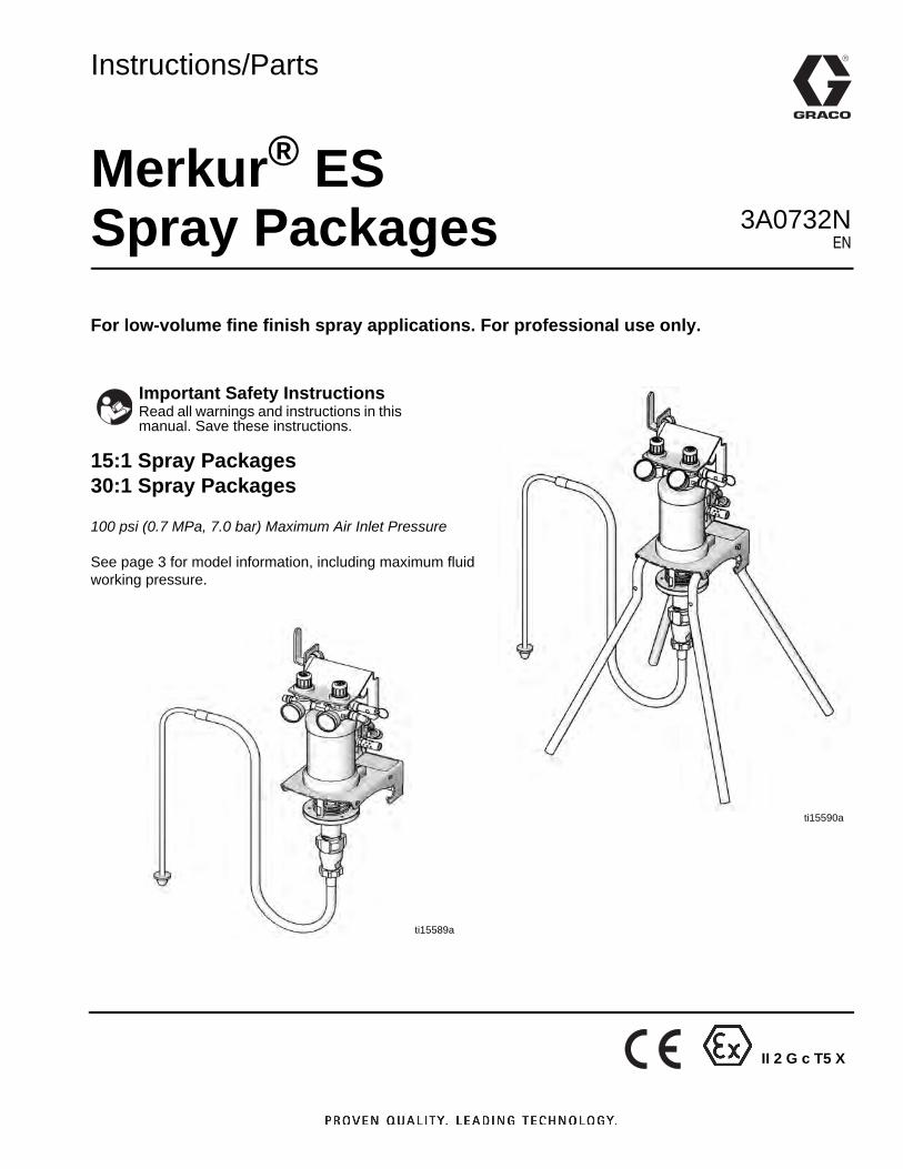
Merkur® ESSpray PackagesFor low-volume fine finish spray applications. For professional use only.
15:1 Spray Packages30:1 Spray Packages
100 psi (0.7 MPa, 7.0 bar) Maximum Air Inlet Pressure
See page 3 for model information, including maximum fluid working pressure.
Important Safety InstructionsRead all warnings and instructions in this manual. Save these instructions.
ti15590a
ti15589a
3A0732NEN
II 2 G c T5 X
2 3A0732N
ContentsModels . . . . . . . . . . . . . . . . . . . . . . . . . . . . . . . . . . . 3Warnings . . . . . . . . . . . . . . . . . . . . . . . . . . . . . . . . . 4Installation . . . . . . . . . . . . . . . . . . . . . . . . . . . . . . . . 7
Prepare the Operator . . . . . . . . . . . . . . . . . . . . . 7Prepare the Site . . . . . . . . . . . . . . . . . . . . . . . . . 7Supplied Components . . . . . . . . . . . . . . . . . . . . . 7Inline Fluid Filter Kits . . . . . . . . . . . . . . . . . . . . . . 7Air Line Accessories . . . . . . . . . . . . . . . . . . . . . . 7Wall Mount Packages . . . . . . . . . . . . . . . . . . . . . 8Grounding . . . . . . . . . . . . . . . . . . . . . . . . . . . . . . 8Flush Before Using Equipment . . . . . . . . . . . . . . 8Setup . . . . . . . . . . . . . . . . . . . . . . . . . . . . . . . . . . 9
Operation . . . . . . . . . . . . . . . . . . . . . . . . . . . . . . . . 10Pressure Relief Procedure . . . . . . . . . . . . . . . . 10Trigger Lock . . . . . . . . . . . . . . . . . . . . . . . . . . . 10Prime the Pump . . . . . . . . . . . . . . . . . . . . . . . . 10Install the Spray Tip . . . . . . . . . . . . . . . . . . . . . 11Adjust the Atomization . . . . . . . . . . . . . . . . . . . 11Adjust the Spray Pattern . . . . . . . . . . . . . . . . . . 12Shutdown . . . . . . . . . . . . . . . . . . . . . . . . . . . . . 12
Maintenance . . . . . . . . . . . . . . . . . . . . . . . . . . . . . . 13Tighten Threaded Connections . . . . . . . . . . . . . 13Flush the Pump . . . . . . . . . . . . . . . . . . . . . . . . . 13
Troubleshooting . . . . . . . . . . . . . . . . . . . . . . . . . . 14Repair . . . . . . . . . . . . . . . . . . . . . . . . . . . . . . . . . . . 15
General Information . . . . . . . . . . . . . . . . . . . . . 15To Remove Intake Valve Only . . . . . . . . . . . . . 15Disconnect the Displacement Pump . . . . . . . . . 15Disassemble the Pump . . . . . . . . . . . . . . . . . . . 16Reassemble the Pump . . . . . . . . . . . . . . . . . . . 16Reconnect the Displacement Pump . . . . . . . . . 16Repair Air Valve . . . . . . . . . . . . . . . . . . . . . . . . 18Replace Pilot Valves . . . . . . . . . . . . . . . . . . . . . 20Disconnect the Air Motor . . . . . . . . . . . . . . . . . . 21Reconnect the Air Motor . . . . . . . . . . . . . . . . . . 21Repair Air Motor . . . . . . . . . . . . . . . . . . . . . . . . 22
Parts . . . . . . . . . . . . . . . . . . . . . . . . . . . . . . . . . . . . 25Package Parts . . . . . . . . . . . . . . . . . . . . . . . . . . 25Hose and Gun . . . . . . . . . . . . . . . . . . . . . . . . . . 29Displacement Pump Parts . . . . . . . . . . . . . . . . 30Air Motor Parts . . . . . . . . . . . . . . . . . . . . . . . . . 32Air Valve Parts . . . . . . . . . . . . . . . . . . . . . . . . . 34Air Control Parts . . . . . . . . . . . . . . . . . . . . . . . . 36
Kits and Accessories . . . . . . . . . . . . . . . . . . . . . . 38Package Dimensions . . . . . . . . . . . . . . . . . . . . . . . 39
Package Weights . . . . . . . . . . . . . . . . . . . . . . . . . . 39Wall Bracket Mounting Hole Diagram . . . . . . . . . 40Technical Data . . . . . . . . . . . . . . . . . . . . . . . . . . . . 41Performance Charts . . . . . . . . . . . . . . . . . . . . . . . . 42
15:1 Ratio Pumps . . . . . . . . . . . . . . . . . . . . . . . 4230:1 Ratio Pumps . . . . . . . . . . . . . . . . . . . . . . . 43
Graco Standard Warranty . . . . . . . . . . . . . . . . . . . 44Graco Information . . . . . . . . . . . . . . . . . . . . . . . . . 44
Models
3A0732N 3
Models
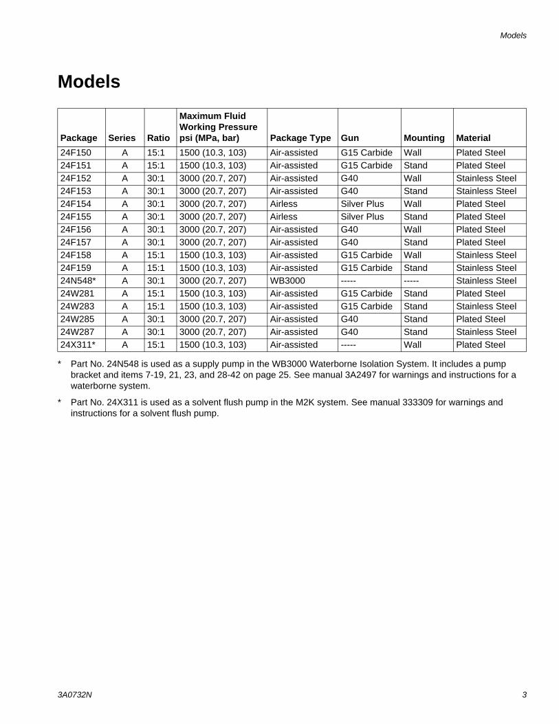
* Part No. 24N548 is used as a supply pump in the WB3000 Waterborne Isolation System. It includes a pump bracket and items 7-19, 21, 23, and 28-42 on page 25. See manual 3A2497 for warnings and instructions for a waterborne system.
* Part No. 24X311 is used as a solvent flush pump in the M2K system. See manual 333309 for warnings and instructions for a solvent flush pump.
Package Series Ratio
Maximum Fluid Working Pressure psi (MPa, bar) Package Type Gun Mounting Material
24F150 A 15:1 1500 (10.3, 103) Air-assisted G15 Carbide Wall Plated Steel24F151 A 15:1 1500 (10.3, 103) Air-assisted G15 Carbide Stand Plated Steel24F152 A 30:1 3000 (20.7, 207) Air-assisted G40 Wall Stainless Steel24F153 A 30:1 3000 (20.7, 207) Air-assisted G40 Stand Stainless Steel24F154 A 30:1 3000 (20.7, 207) Airless Silver Plus Wall Plated Steel24F155 A 30:1 3000 (20.7, 207) Airless Silver Plus Stand Plated Steel24F156 A 30:1 3000 (20.7, 207) Air-assisted G40 Wall Plated Steel24F157 A 30:1 3000 (20.7, 207) Air-assisted G40 Stand Plated Steel24F158 A 15:1 1500 (10.3, 103) Air-assisted G15 Carbide Wall Stainless Steel24F159 A 15:1 1500 (10.3, 103) Air-assisted G15 Carbide Stand Stainless Steel24N548* A 30:1 3000 (20.7, 207) WB3000 ----- ----- Stainless Steel24W281 A 15:1 1500 (10.3, 103) Air-assisted G15 Carbide Stand Plated Steel24W283 A 15:1 1500 (10.3, 103) Air-assisted G15 Carbide Stand Stainless Steel24W285 A 30:1 3000 (20.7, 207) Air-assisted G40 Stand Plated Steel24W287 A 30:1 3000 (20.7, 207) Air-assisted G40 Stand Stainless Steel24X311* A 15:1 1500 (10.3, 103) Air-assisted ----- Wall Plated Steel
Warnings
4 3A0732N
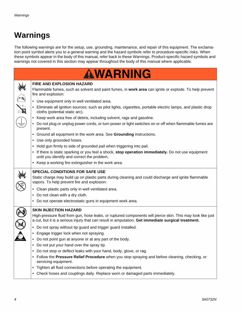
WarningsThe following warnings are for the setup, use, grounding, maintenance, and repair of this equipment. The exclama-tion point symbol alerts you to a general warning and the hazard symbols refer to procedure-specific risks. When these symbols appear in the body of this manual, refer back to these Warnings. Product-specific hazard symbols and warnings not covered in this section may appear throughout the body of this manual where applicable.
WARNINGWARNINGWARNINGWARNINGFIRE AND EXPLOSION HAZARDFlammable fumes, such as solvent and paint fumes, in work area can ignite or explode. To help prevent fire and explosion:
• Use equipment only in well ventilated area.• Eliminate all ignition sources; such as pilot lights, cigarettes, portable electric lamps, and plastic drop
cloths (potential static arc). • Keep work area free of debris, including solvent, rags and gasoline.• Do not plug or unplug power cords, or turn power or light switches on or off when flammable fumes are
present.• Ground all equipment in the work area. See Grounding instructions.• Use only grounded hoses.• Hold gun firmly to side of grounded pail when triggering into pail.• If there is static sparking or you feel a shock, stop operation immediately. Do not use equipment
until you identify and correct the problem.• Keep a working fire extinguisher in the work area.
SPECIAL CONDITIONS FOR SAFE USEStatic charge may build up on plastic parts during cleaning and could discharge and ignite flammable vapors. To help prevent fire and explosion:
• Clean plastic parts only in well ventilated area. • Do not clean with a dry cloth. • Do not operate electrostatic guns in equipment work area.
SKIN INJECTION HAZARDHigh-pressure fluid from gun, hose leaks, or ruptured components will pierce skin. This may look like just a cut, but it is a serious injury that can result in amputation. Get immediate surgical treatment.
• Do not spray without tip guard and trigger guard installed.• Engage trigger lock when not spraying.• Do not point gun at anyone or at any part of the body.• Do not put your hand over the spray tip.• Do not stop or deflect leaks with your hand, body, glove, or rag.• Follow the Pressure Relief Procedure when you stop spraying and before cleaning, checking, or
servicing equipment. • Tighten all fluid connections before operating the equipment.• Check hoses and couplings daily. Replace worn or damaged parts immediately.
Warnings
3A0732N 5
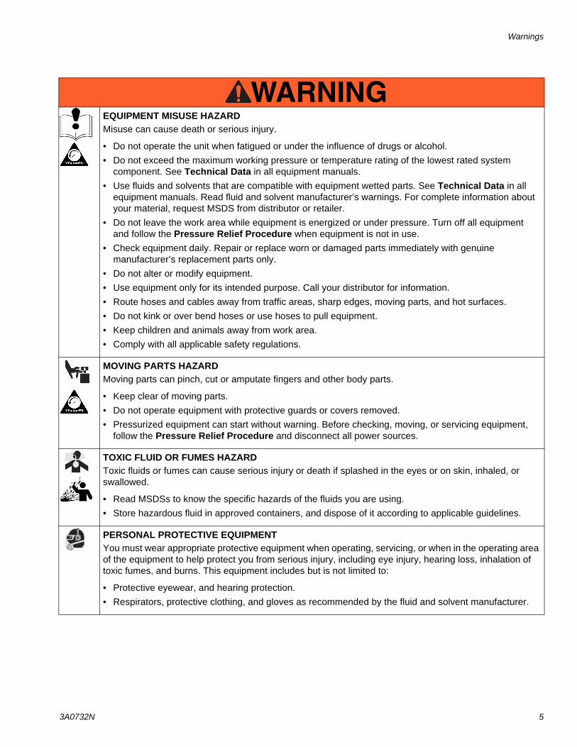
EQUIPMENT MISUSE HAZARDMisuse can cause death or serious injury.
• Do not operate the unit when fatigued or under the influence of drugs or alcohol.• Do not exceed the maximum working pressure or temperature rating of the lowest rated system
component. See Technical Data in all equipment manuals.• Use fluids and solvents that are compatible with equipment wetted parts. See Technical Data in all
equipment manuals. Read fluid and solvent manufacturer’s warnings. For complete information about your material, request MSDS from distributor or retailer.
• Do not leave the work area while equipment is energized or under pressure. Turn off all equipment and follow the Pressure Relief Procedure when equipment is not in use.
• Check equipment daily. Repair or replace worn or damaged parts immediately with genuine manufacturer’s replacement parts only.
• Do not alter or modify equipment.• Use equipment only for its intended purpose. Call your distributor for information.• Route hoses and cables away from traffic areas, sharp edges, moving parts, and hot surfaces.• Do not kink or over bend hoses or use hoses to pull equipment.• Keep children and animals away from work area.• Comply with all applicable safety regulations.
MOVING PARTS HAZARDMoving parts can pinch, cut or amputate fingers and other body parts.
• Keep clear of moving parts.• Do not operate equipment with protective guards or covers removed.• Pressurized equipment can start without warning. Before checking, moving, or servicing equipment,
follow the Pressure Relief Procedure and disconnect all power sources.
TOXIC FLUID OR FUMES HAZARDToxic fluids or fumes can cause serious injury or death if splashed in the eyes or on skin, inhaled, or swallowed.
• Read MSDSs to know the specific hazards of the fluids you are using.• Store hazardous fluid in approved containers, and dispose of it according to applicable guidelines.
PERSONAL PROTECTIVE EQUIPMENTYou must wear appropriate protective equipment when operating, servicing, or when in the operating area of the equipment to help protect you from serious injury, including eye injury, hearing loss, inhalation of toxic fumes, and burns. This equipment includes but is not limited to:
• Protective eyewear, and hearing protection. • Respirators, protective clothing, and gloves as recommended by the fluid and solvent manufacturer.
WARNINGWARNINGWARNINGWARNING
Warnings
6 3A0732N
Installation
3A0732N 7
Installation
Prepare the OperatorAll persons who operate the equipment must be trained in the safe, efficient operation of all system components as well as the proper handling of all fluids. All operators must thoroughly read all instruction manuals, tags, and labels before operating the equipment.
Prepare the SiteEnsure that you have an adequate compressed airsupply.
Bring a compressed air supply line from the air com-pressor to the pump location. Be sure all air hoses are properly sized and pressure-rated for your system. Use only electrically conductive hoses. The air hose should have a 3/8 npt(m) thread. A quick disconnect coupling is recommended.
Keep the site clear of any obstacles or debris that could interfere with the operator's movement.
Have a grounded, metal pail available for use when flushing the system.
Supplied ComponentsSee FIG. 2 on page 9.
• The red-handled bleed-type master air valve (D) is required in your system to relieve air trapped between it and the air motor and gun when the valve is closed. Do not block access to the valve.
• The pump air regulator (F) controls pump speed and outlet pressure by adjusting the air pressure to the pump.
• The air pressure relief valve (P) opens automati-cally to prevent overpressurization of the pump.
• The gun air regulator (E) adjusts the air pressure to the air-assisted spray gun.
• The spray gun (H) dispenses the fluid. The gun houses the spray tip (not shown), which is available in a wide range of sizes for different spray patterns and rates of flow. Refer to gun manual for tip instal-lation.
• The red hose (G) provides the gun air supply.
• The blue hose (K) provides the gun fluid supply.
• The suction kit with strainer (J) allows the pump to draw fluid from a 5 gallon (19 liter) pail.
Inline Fluid Filter KitsInline fluid filter kits are available as an accessory in stainless steel (24F271) or aluminum (24F272), to filter particles from fluid as it leaves the pump. Kits include a 60 mesh (250 micron) stainless steel element.
Air Line AccessoriesInstall the following accessories in the order shown in FIG. 2, using adapters as necessary.
• An air-line filter (C) removes harmful dirt and mois-ture from the compressed air supply.
• A second bleed-type air shutoff valve (B) isolates the air line accessories for servicing. Locate upstream from all other air line accessories.
Installation
8 3A0732N
Wall Mount Packages1. Be sure the wall can support the weight of the
pump, bracket, hoses and accessories, as well as the stress caused during operation.
2. Position the wall bracket at a convenient height. Do not stretch the suction hose tight; let it hang to assist fluid flow into the pump. For ease of operation and service, make sure the pump air inlet, fluid inlet, and fluid outlet ports are easily accessible.
3. Using the wall bracket as a template, drill mounting holes in the wall. Hole diameters and wall mounting dimensions are shown on page 40.
4. Attach the bracket to the wall. Use screws that are long enough to keep the pump from vibrating during operation.
NOTE: Be sure the bracket is level.
Grounding
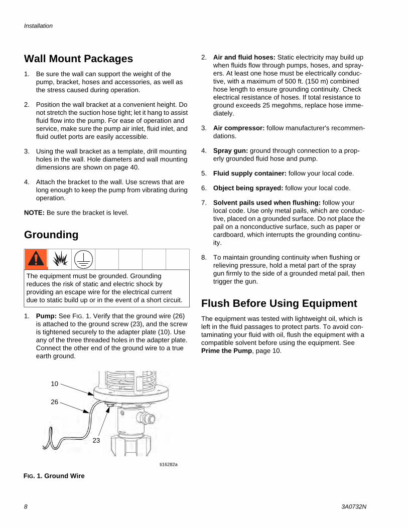
1. Pump: See FIG. 1. Verify that the ground wire (26) is attached to the ground screw (23), and the screw is tightened securely to the adapter plate (10). Use any of the three threaded holes in the adapter plate. Connect the other end of the ground wire to a true earth ground.
2. Air and fluid hoses: Static electricity may build up when fluids flow through pumps, hoses, and spray-ers. At least one hose must be electrically conduc-tive, with a maximum of 500 ft. (150 m) combined hose length to ensure grounding continuity. Check electrical resistance of hoses. If total resistance to ground exceeds 25 megohms, replace hose imme-diately.
3. Air compressor: follow manufacturer's recommen-dations.
4. Spray gun: ground through connection to a prop-erly grounded fluid hose and pump.
5. Fluid supply container: follow your local code.
6. Object being sprayed: follow your local code.
7. Solvent pails used when flushing: follow your local code. Use only metal pails, which are conduc-tive, placed on a grounded surface. Do not place the pail on a nonconductive surface, such as paper or cardboard, which interrupts the grounding continu-ity.
8. To maintain grounding continuity when flushing or relieving pressure, hold a metal part of the spray gun firmly to the side of a grounded metal pail, then trigger the gun.
Flush Before Using EquipmentThe equipment was tested with lightweight oil, which is left in the fluid passages to protect parts. To avoid con-taminating your fluid with oil, flush the equipment with a compatible solvent before using the equipment. See Prime the Pump, page 10.
The equipment must be grounded. Grounding reduces the risk of static and electric shock by providing an escape wire for the electrical current due to static build up or in the event of a short circuit.
FIG. 1. Ground Wire
23
26
ti16282a
10
Installation
3A0732N 9
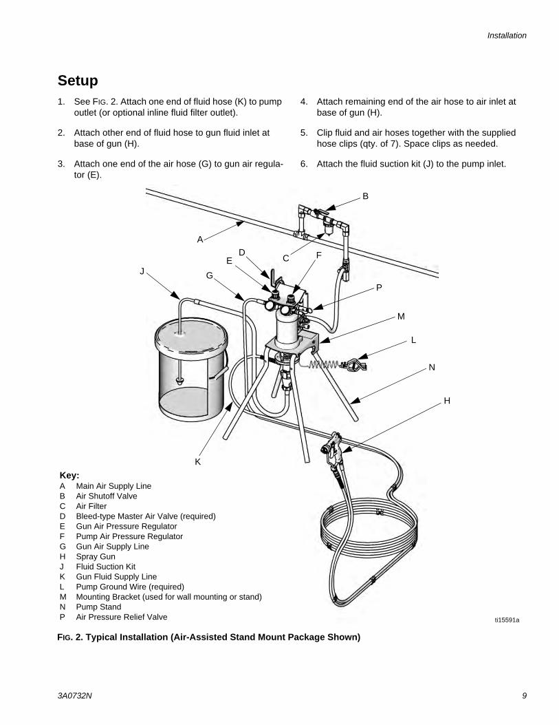
Setup1. See FIG. 2. Attach one end of fluid hose (K) to pump
outlet (or optional inline fluid filter outlet).
2. Attach other end of fluid hose to gun fluid inlet at base of gun (H).
3. Attach one end of the air hose (G) to gun air regula-tor (E).
4. Attach remaining end of the air hose to air inlet at base of gun (H).
5. Clip fluid and air hoses together with the supplied hose clips (qty. of 7). Space clips as needed.
6. Attach the fluid suction kit (J) to the pump inlet.
FIG. 2. Typical Installation (Air-Assisted Stand Mount Package Shown)
A
B
CD FE
G
N
J
K
L
ti15591a
H
M
P
Key:A Main Air Supply LineB Air Shutoff ValveC Air FilterD Bleed-type Master Air Valve (required)E Gun Air Pressure RegulatorF Pump Air Pressure RegulatorG Gun Air Supply Line H Spray GunJ Fluid Suction KitK Gun Fluid Supply LineL Pump Ground Wire (required)M Mounting Bracket (used for wall mounting or stand)N Pump StandP Air Pressure Relief Valve
Operation
10 3A0732N
Operation
Pressure Relief Procedure
1. Lock the gun trigger.
2. See FIG. 2. Turn off the bleed-type master air valve (D).
3. Unlock the gun trigger.
4. Hold a metal part of the gun firmly to a grounded metal waste container. Trigger the gun to relieve fluid pressure.
5. Lock the gun trigger.
6. If you suspect that pressure has not been fully relieved after following the steps above, check the following:
a. The spray tip may be completely clogged. Very slowly loosen the air cap retaining ring to relieve pressure in the cavity between the ball/seat shutoff and the plugged tip. Clear the tip orifice.
b. The gun fluid filter or the fluid hose may be com-pletely clogged. Very slowly loosen the hose end coupling at the gun and relieve pressure gradually. Then loosen completely to clear the obstruction.
c. After following the steps above, if the spray tip or hose still seems completely clogged, very slowly loosen the tip guard retaining nut or hose end coupling and relieve pressure gradually, then loosen completely. With tip removed, trig-ger gun into waste container.
Trigger Lock
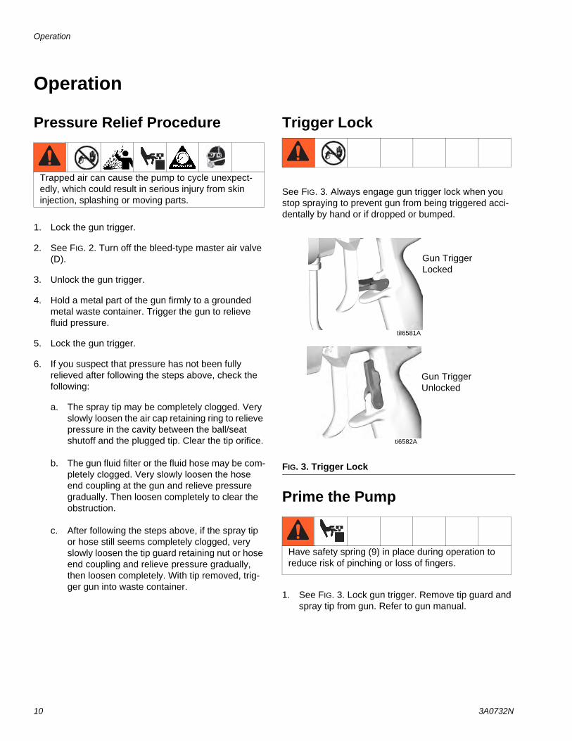
See FIG. 3. Always engage gun trigger lock when you stop spraying to prevent gun from being triggered acci-dentally by hand or if dropped or bumped.
Prime the Pump
1. See FIG. 3. Lock gun trigger. Remove tip guard and spray tip from gun. Refer to gun manual.
Trapped air can cause the pump to cycle unexpect-edly, which could result in serious injury from skin injection, splashing or moving parts.
FIG. 3. Trigger Lock
Have safety spring (9) in place during operation to reduce risk of pinching or loss of fingers.
tiI6581A
ti6582A
Gun Trigger Locked
Gun Trigger Unlocked
Operation
3A0732N 11
2. See FIG. 2. Close gun air regulator (E) and pump air regulator (F) by turning knobs counterclockwise reducing pressure to zero. Close bleed-type air valve (D).
3. Connect air line to bleed type air valve.
4. Check that all fittings throughout system are tight-ened securely.
5. Position pail close to pump. Suction hose is 3 ft (0.9 m) long. Do not stretch hose tight; let it hang to assist fluid flow into pump.
6. Hold metal part of gun firmly to side of grounded metal pail, unlock trigger, and hold trigger open.
7. Open bleed-type air valve. Slowly turn pump air reg-ulator clockwise, increasing pressure until pump starts.
8. Cycle pump slowly until all air is pushed out and pump and hoses are fully primed.
9. Release gun trigger and lock trigger safety. Pump should stall against pressure.
Install the Spray Tip
Follow Pressure Relief Procedure, page 10. Install the spray tip and tip guard as explained in your separate gun manual, supplied.
The fluid output and pattern width depend on the size of the spray tip, the fluid viscosity, and the fluid pressure. Use the Spray Tip Selection Chart in your gun instruc-tion manual as a guide for selecting an appropriate spray tip for your application.
NOTE: The maximum recommended spray tip size is .019 in. (0.483 mm).
Adjust the Atomization
NOTE: Use this procedure with airless and air-assisted spray guns.
1. Do not turn on atomizing air supply. Fluid pressure is controlled by the air pressure supplied to the pump (pump air regulator). Set fluid pressure at low starting pressure. For low viscosity fluids (less than 25 sec, #2 Zahn cup) with lower percent solids (typi-cally less than 40%), start at 300 psi (2.1 MPa, 21 bar) at pump outlet. For fluids with higher viscosity or higher solids content, start at 600 psi (4.2 MPa, 42 bar). Refer to the following example.
Example:
2. Hold gun perpendicular and approximately 12 inches (304 mm) from surface.
3. Move gun first, then pull gun trigger to spray onto test paper.
4. Increase fluid pressure in 100 psi (0.7 MPa, 7 bar) increments, just to the point where a further increase in fluid pressure does not significantly improve fluid atomization. Refer to the following example.
Example:
5. If you are using an air-assisted spray gun, see Adjust the Spray Pattern on page 12.
Pump Ratio
Pump Air Regulator Setting
psi (MPa, bar)
Approximate Fluid Pressurepsig (MPa, bar)
15:1 x 20 (0.14, 1.4) = 300 (2.1, 21)30:1 x 20 (0.14, 1.4) = 600 (4.2, 42)
Pump Ratio
Pump Air Regulator Increment
psi (MPa, bar)
Incremental Fluid Pressurepsi (MPa, bar)
15:1 x 7 (.05, 0.5) = 100 (0.7, 7.0)30:1 x 3.3 (0.02, 0.2) = 100 (0.7, 7.0)
Operation
12 3A0732N
Adjust the Spray Pattern
NOTE: Use this procedure with air-assisted spray guns only.
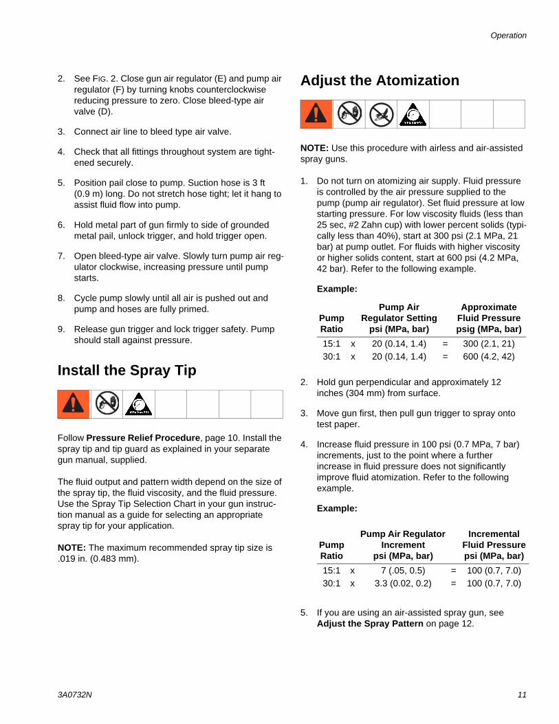
1. See FIG. 4. Close off pattern adjustment air by turn-ing knob (AA) clockwise (in) all the way. This sets gun for its widest pattern.
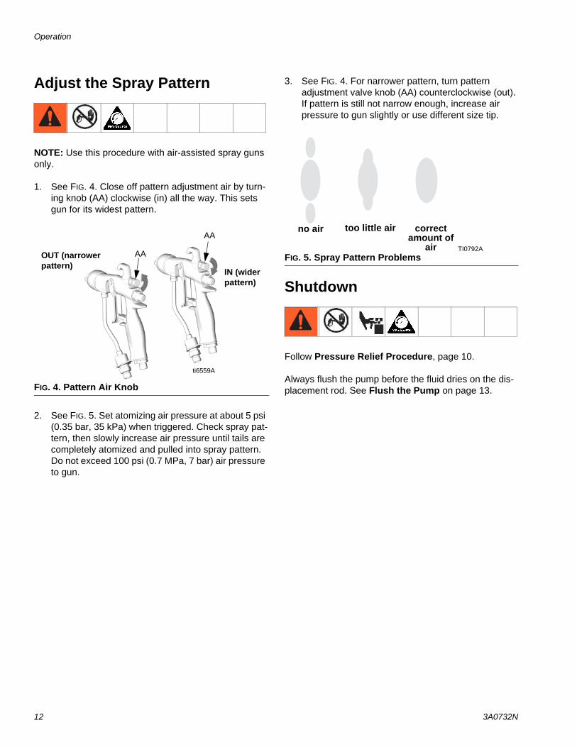
2. See FIG. 5. Set atomizing air pressure at about 5 psi (0.35 bar, 35 kPa) when triggered. Check spray pat-tern, then slowly increase air pressure until tails are completely atomized and pulled into spray pattern. Do not exceed 100 psi (0.7 MPa, 7 bar) air pressure to gun.
3. See FIG. 4. For narrower pattern, turn pattern adjustment valve knob (AA) counterclockwise (out). If pattern is still not narrow enough, increase air pressure to gun slightly or use different size tip.
Shutdown
Follow Pressure Relief Procedure, page 10.
Always flush the pump before the fluid dries on the dis-placement rod. See Flush the Pump on page 13.FIG. 4. Pattern Air Knob
ti6559A
OUT (narrower pattern)
IN (wider pattern)
AA
AA
FIG. 5. Spray Pattern Problems
no air too little air correct amount of
air TI0792A
Maintenance
3A0732N 13
Maintenance
Tighten Threaded ConnectionsBefore each use, check all hoses for wear or damage. Replace as necessary. Check that all threaded connec-tions are tight and leak-free.
Flush the Pump
Flush the pump:
• Before first use
• When changing colors or fluids
• Before repairing equipment
• Before fluid dries or settles out in a dormant pump (check the pot life of catalyzed fluids)
• At the end of the day
• Before storing the pump.
Flush at the lowest pressure possible. Flush with a fluid that is compatible with the fluid you are pumping and with the wetted parts in your system. Check with your fluid manufacturer or supplier for recommended flushing fluids and flushing frequency.
1. Follow Pressure Relief Procedure, page 10.
2. Remove tip guard and spray tip from gun. Refer to separate gun manual.
3. Place suction tube in grounded metal pail containing cleaning fluid.
4. Set pump to lowest possible fluid pressure, and start pump.
5. Hold a metal part of the gun firmly to a grounded metal pail.
6. Trigger gun. Flush system until clear solvent flows from gun.
7. Follow Pressure Relief Procedure, page 10.
8. Clean the tip guard, spray tip, and fluid filter element separately, then reinstall them.
9. Clean inside and outside of suction tube and suction hose.
Read all Warnings. Follow all Grounding instruc-tions. See page 8.
Troubleshooting
14 3A0732N
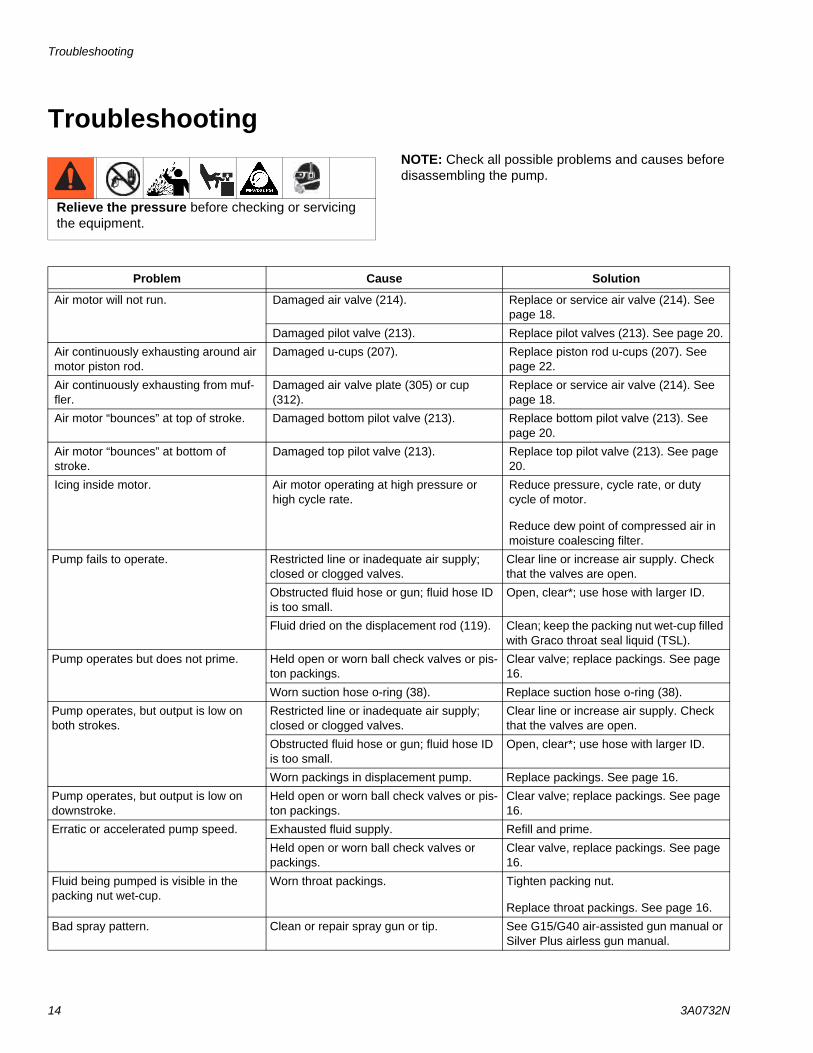
TroubleshootingNOTE: Check all possible problems and causes before disassembling the pump.
Relieve the pressure before checking or servicing the equipment.
Problem Cause Solution
Air motor will not run. Damaged air valve (214). Replace or service air valve (214). See page 18.
Damaged pilot valve (213). Replace pilot valves (213). See page 20.
Air continuously exhausting around air motor piston rod.
Damaged u-cups (207). Replace piston rod u-cups (207). See page 22.
Air continuously exhausting from muf-fler.
Damaged air valve plate (305) or cup (312).
Replace or service air valve (214). See page 18.
Air motor “bounces” at top of stroke. Damaged bottom pilot valve (213). Replace bottom pilot valve (213). See page 20.
Air motor “bounces” at bottom of stroke.
Damaged top pilot valve (213). Replace top pilot valve (213). See page 20.
Icing inside motor. Air motor operating at high pressure or high cycle rate.
Reduce pressure, cycle rate, or duty cycle of motor.
Reduce dew point of compressed air in moisture coalescing filter.
Pump fails to operate. Restricted line or inadequate air supply; closed or clogged valves.
Clear line or increase air supply. Check that the valves are open.
Obstructed fluid hose or gun; fluid hose ID is too small.
Open, clear*; use hose with larger ID.
Fluid dried on the displacement rod (119). Clean; keep the packing nut wet-cup filled with Graco throat seal liquid (TSL).
Pump operates but does not prime. Held open or worn ball check valves or pis-ton packings.
Clear valve; replace packings. See page 16.
Worn suction hose o-ring (38). Replace suction hose o-ring (38).
Pump operates, but output is low on both strokes.
Restricted line or inadequate air supply; closed or clogged valves.
Clear line or increase air supply. Check that the valves are open.
Obstructed fluid hose or gun; fluid hose ID is too small.
Open, clear*; use hose with larger ID.
Worn packings in displacement pump. Replace packings. See page 16.
Pump operates, but output is low on downstroke.
Held open or worn ball check valves or pis-ton packings.
Clear valve; replace packings. See page 16.
Erratic or accelerated pump speed. Exhausted fluid supply. Refill and prime.
Held open or worn ball check valves or packings.
Clear valve, replace packings. See page 16.
Fluid being pumped is visible in the packing nut wet-cup.
Worn throat packings. Tighten packing nut.
Replace throat packings. See page 16.
Bad spray pattern. Clean or repair spray gun or tip. See G15/G40 air-assisted gun manual or Silver Plus airless gun manual.
Repair
3A0732N 15
Repair
General Information• Reference numbers and letters in parentheses in
the text refer to the callouts in the figures and the parts drawing.
• Always use Genuine Graco Parts and Accessories, available from your Graco distributor. If you supply your own accessories, be sure they are adequately sized and pressure rated for your system.
To Remove Intake Valve OnlyThe intake ball and seat may be cleaned or serviced without disconnecting the displacement pump.
1. Stop the pump.
2. Flush the pump, if possible (see page 13). Follow Pressure Relief Procedure, page 10.
3. Disconnect the suction hose.
4. Remove the intake housing (110). See FIG. 7.
5. Clean or replace the ball guide (109), ball (116), seat (117), and o-ring (111).
6. Install the o-ring (111‡), seat (117), intake ball (116‡), and ball guide (109) in the intake housing (110).
7. Screw the intake housing (110) onto the cylinder (105). Torque to 70-80 ft-lb (95-108 N•m).
Disconnect the Displacement Pump
1. Stop the pump.
2. Flush the pump, if possible (see page 13). Follow Pressure Relief Procedure, page 10.
3. Disconnect the air hose, fluid hose, and suction hose.
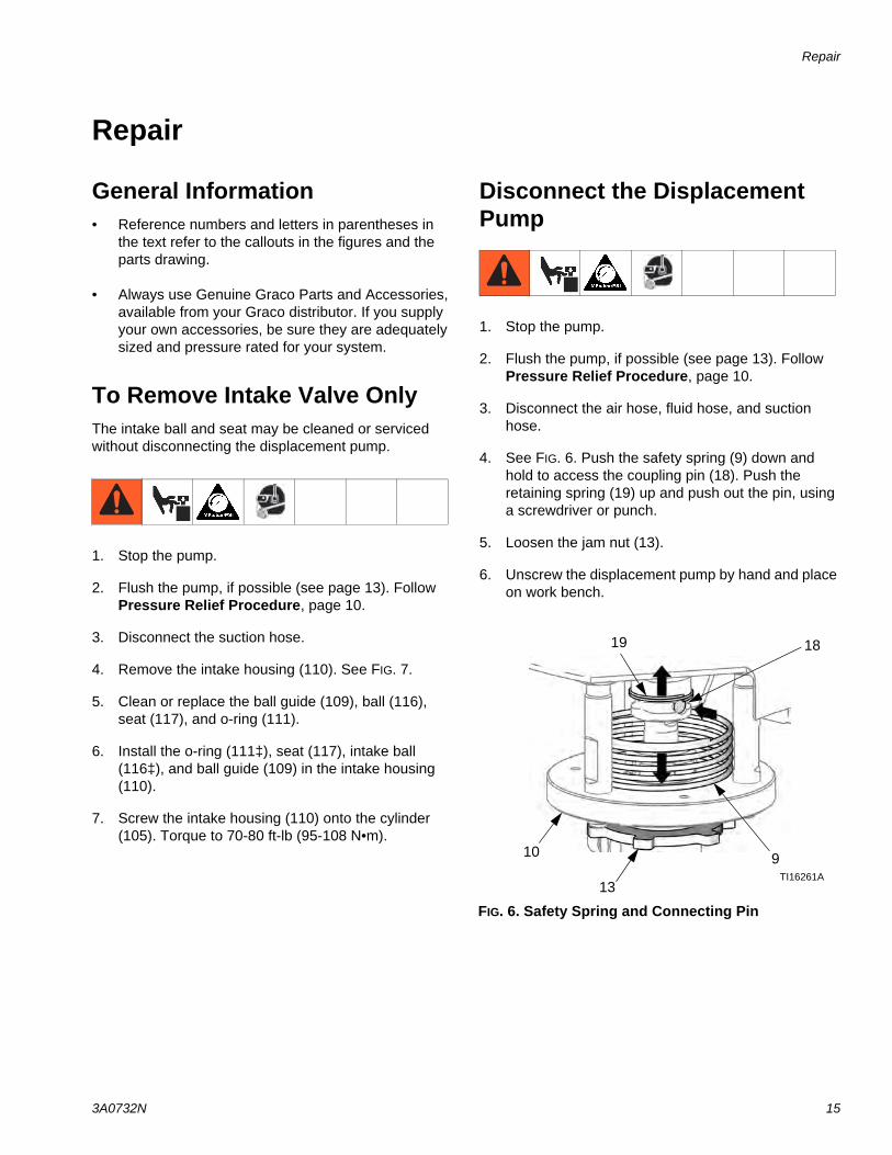
4. See FIG. 6. Push the safety spring (9) down and hold to access the coupling pin (18). Push the retaining spring (19) up and push out the pin, using a screwdriver or punch.
5. Loosen the jam nut (13).
6. Unscrew the displacement pump by hand and place on work bench.
FIG. 6. Safety Spring and Connecting Pin
19
9
18
TI16261A13
10
Repair
16 3A0732N
Disassemble the PumpNOTE: Pump Repair Kits are available. See page 31 to order the correct kit for your pump. Parts are marked with an ‡.
1. Follow the instructions under Disconnect the Dis-placement Pump, page 15.
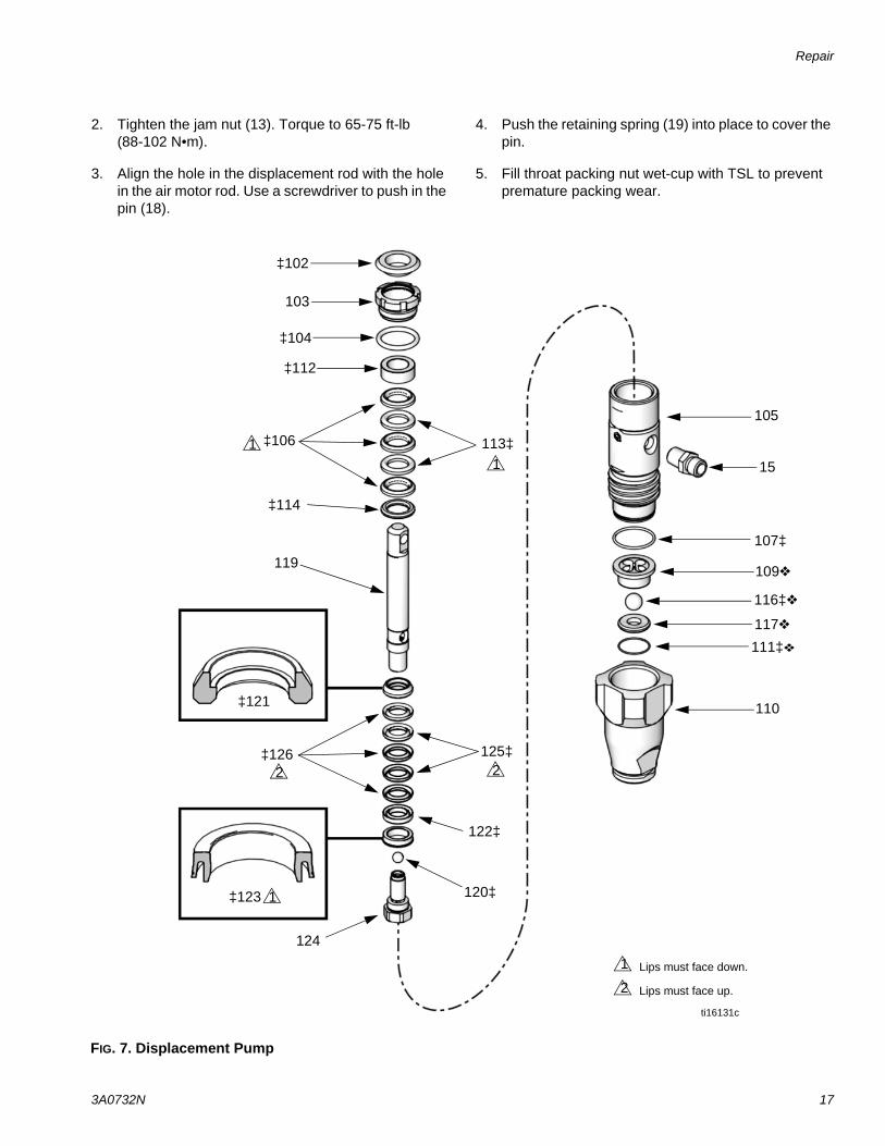
1. See FIG. 7. Loosen the packing nut (103), using a screwdriver and hammer. Remove the o-ring (104).
2. Unscrew the cylinder (105) from the intake housing (110). The rod and piston assembly will come with the cylinder.
3. Remove the ball guide (109), intake ball (116), seat (117), and o-ring (111) from the intake housing (110).
4. Drive the rod and piston assembly out the bottom of the cylinder. Remove the o-ring (107) from the cylin-der.
5. Insert a plastic rod in the bottom of the cylinder and drive the throat packings and glands out the top.
6. Put the rod (119) in a vise and unscrew the piston (124). Be careful not to drop the piston ball (120). Disassemble the piston packings from the piston.
7. Clean and inspect all parts. Replace any damaged parts.
Reassemble the PumpNOTE: Soak the leather packings (113‡, 125‡) in hydraulic oil for one hour before installing them in the pump.
1. Install the piston wiper (123‡) on the piston (124), with the lips facing down. Install the female gland (122‡). Install the piston packings in the following order with the lips facing up: blue UHMWPE (126‡), leather (125‡), UHMWPE, leather, UHMWPE. Install the male gland (121‡).
2. Put the displacement rod (119) in a vise. Place the piston ball (120‡) in the cavity of the rod. Screw the piston assembly into the rod. Torque to 24-30 ft-lb (33-40 N•m).
3. Install the male gland (114‡) in the cylinder (105). Install the throat packings in the following order with the lips facing down: blue UHMWPE (106‡), leather (113‡), UHMWPE, leather, UHMWPE. Install the female gland (112‡).
4. Install the o-ring (104‡) on the packing nut (103). Loosely install the packing nut in the cylinder.
5. Liberally lubricate the piston packings and the top 2 in. (51 mm) of the displacement rod (119).
6. Push the displacement rod (119) into the cylinder (105) from the bottom until the piston is completely in the cylinder and the rod protrudes from the pack-ing nut (103).
7. Grease the o-ring (107‡) and install it on the cylin-der (105).
8. Install the o-ring (111‡), seat (117), intake ball (116‡), and ball guide (109) in the intake housing (110).
9. Place the intake housing (110) in a vise. Screw the cylinder (105) into the intake housing. Torque to 70-80 ft-lb (95-108 N•m).
10. Tighten the packing nut (103) 1/2 turn past hand-tight, or torque to 60-80 in-lb (6.7-9.0 N•m).
11. Ensure that the button plug (102‡) is in place on the packing nut (103).
12. Follow the instructions under Reconnect the Dis-placement Pump, page 16.
Reconnect the Displacement Pump
1. Screw the displacement pump into the adapter plate (10) until it stops. Back off pump less than 1 turn, to align pump outlet as desired.
NOTICEThe displacement pump can be damaged if the stroke is not centered when the pump is reconnected. Be sure to fully screw the displacement pump into the adapter plate (10).
Repair
3A0732N 17
2. Tighten the jam nut (13). Torque to 65-75 ft-lb (88-102 N•m).
3. Align the hole in the displacement rod with the hole in the air motor rod. Use a screwdriver to push in the pin (18).
4. Push the retaining spring (19) into place to cover the pin.
5. Fill throat packing nut wet-cup with TSL to prevent premature packing wear.
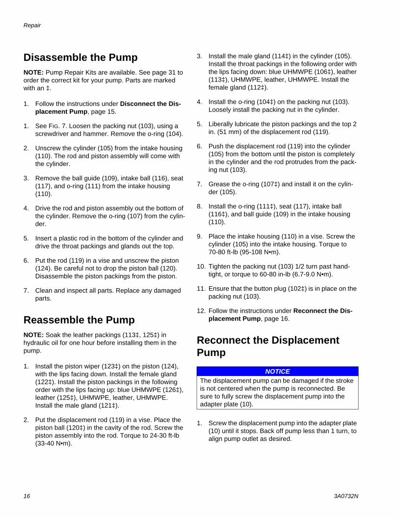
FIG. 7. Displacement Pump
ti16131c
119
125‡
117
116‡
110
113‡
‡123
‡102
‡106
103
‡112
107‡
111‡
109
122‡
‡121
120‡
‡114
105
124
‡104
‡126
15
1
Lips must face down.
Lips must face up.
1
2
1
1
2 2
Repair
18 3A0732N
Repair Air Valve
Replace Complete Air Valve1. Stop the pump. Follow Pressure Relief Procedure,
page 10.
2. Disconnect the air line to the motor.
3. See FIG. 14 on page 23. Remove four screws (211). Remove the air valve (214) and gasket (209*).
4. To repair the air valve, go to Disassemble the Air Valve, page 18. To install a replacement air valve, continue with step 5.
5. Align the new air valve gasket (209*) on the mani-fold, then attach the air valve (214). Torque screws (211) to 95-105 in-lb (11-12 N•m).
6. Reconnect the air line to the motor.
Replace Seals or Rebuild Air ValveNOTE: Air Valve Seal Kits are available. See page 35. Parts are marked with an †.
Air Valve Repair Kits are available. See page 35. Parts are marked with an .
Air Valve End Cap Kits are available. See page 35. Parts are marked with an .
Disassemble the Air Valve
1. Perform steps 1-3 under Replace Complete Air Valve, page 18.
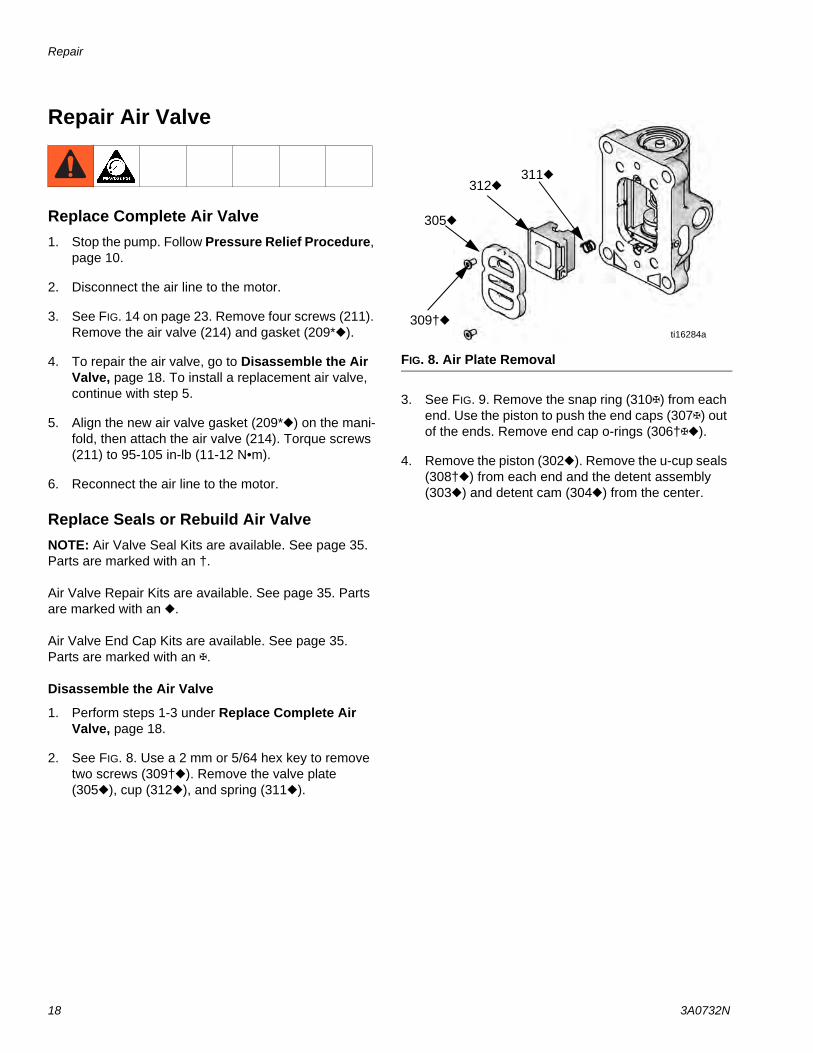
2. See FIG. 8. Use a 2 mm or 5/64 hex key to remove two screws (309†). Remove the valve plate (305), cup (312), and spring (311).
3. See FIG. 9. Remove the snap ring (310) from each end. Use the piston to push the end caps (307) out of the ends. Remove end cap o-rings (306†).
4. Remove the piston (302). Remove the u-cup seals (308†) from each end and the detent assembly (303) and detent cam (304) from the center.
FIG. 8. Air Plate Removal
309†
305
312311
ti16284a
Repair
3A0732N 19
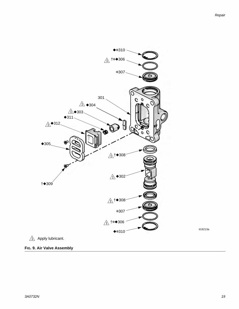
FIG. 9. Air Valve Assembly
1 Apply lubricant.
310
307
307
†309
305
312
311303
302
†308
†308
301
304
310ti16213a
†306
†306
1
1
1
1
1
1
1
1
Repair
20 3A0732N
Reassemble the Air Valve
1. See FIG. 9. Lubricate detent cam (304) and install into housing.
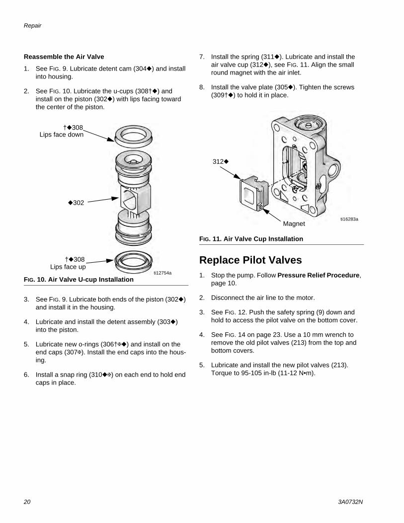
2. See FIG. 10. Lubricate the u-cups (308†) and install on the piston (302) with lips facing toward the center of the piston.
3. See FIG. 9. Lubricate both ends of the piston (302) and install it in the housing.
4. Lubricate and install the detent assembly (303) into the piston.
5. Lubricate new o-rings (306†) and install on the end caps (307). Install the end caps into the hous-ing.
6. Install a snap ring (310) on each end to hold end caps in place.
7. Install the spring (311). Lubricate and install the air valve cup (312), see FIG. 11. Align the small round magnet with the air inlet.
8. Install the valve plate (305). Tighten the screws (309†) to hold it in place.
Replace Pilot Valves1. Stop the pump. Follow Pressure Relief Procedure,
page 10.
2. Disconnect the air line to the motor.
3. See FIG. 12. Push the safety spring (9) down and hold to access the pilot valve on the bottom cover.
4. See FIG. 14 on page 23. Use a 10 mm wrench to remove the old pilot valves (213) from the top and bottom covers.
5. Lubricate and install the new pilot valves (213). Torque to 95-105 in-lb (11-12 N•m).
FIG. 10. Air Valve U-cup Installation
Lips face down
Lips face up
†308
†308
302
ti12754a
FIG. 11. Air Valve Cup Installation
312
ti16283aMagnet
Repair
3A0732N 21
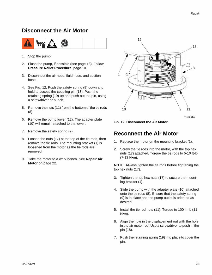
Disconnect the Air Motor
1. Stop the pump.
2. Flush the pump, if possible (see page 13). Follow Pressure Relief Procedure, page 10.
3. Disconnect the air hose, fluid hose, and suction hose.
4. See FIG. 12. Push the safety spring (9) down and hold to access the coupling pin (18). Push the retaining spring (19) up and push out the pin, using a screwdriver or punch.
5. Remove the nuts (11) from the bottom of the tie rods (8).
6. Remove the pump lower (12). The adapter plate (10) will remain attached to the lower.
7. Remove the safety spring (9).
8. Loosen the nuts (17) at the top of the tie rods, then remove the tie rods. The mounting bracket (1) is loosened from the motor as the tie rods are removed.
9. Take the motor to a work bench. See Repair Air Motor on page 22.
Reconnect the Air Motor1. Replace the motor on the mounting bracket (1).
2. Screw the tie rods into the motor, with the top hex nuts (17) attached. Torque the tie rods to 5-10 ft-lb (7-13 N•m).
NOTE: Always tighten the tie rods before tightening the top hex nuts (17).
3. Tighten the top hex nuts (17) to secure the mount-ing bracket (1).
4. Slide the pump with the adapter plate (10) attached onto the tie rods (8). Ensure that the safety spring (9) is in place and the pump outlet is oriented as desired.
5. Install the tie rod nuts (11). Torque to 100 in-lb (11 N•m).
6. Align the hole in the displacement rod with the hole in the air motor rod. Use a screwdriver to push in the pin (18).
7. Push the retaining spring (19) into place to cover the pin.
FIG. 12. Disconnect the Air Motor
19
9
18
TI16261A
11
8
10
1 17
Repair
22 3A0732N
Repair Air Motor
NOTE: Complete Air Motor Replacement Kits are avail-able. Order 24G693 (2.5 in. motor) or 24G694 (3.5 in. motor).
NOTE: Air Motor Seal Kits are available. See page 33 for the correct kit for your motor. Parts included in the kit are marked with an asterisk (*). For best results, use all the parts in the kit.
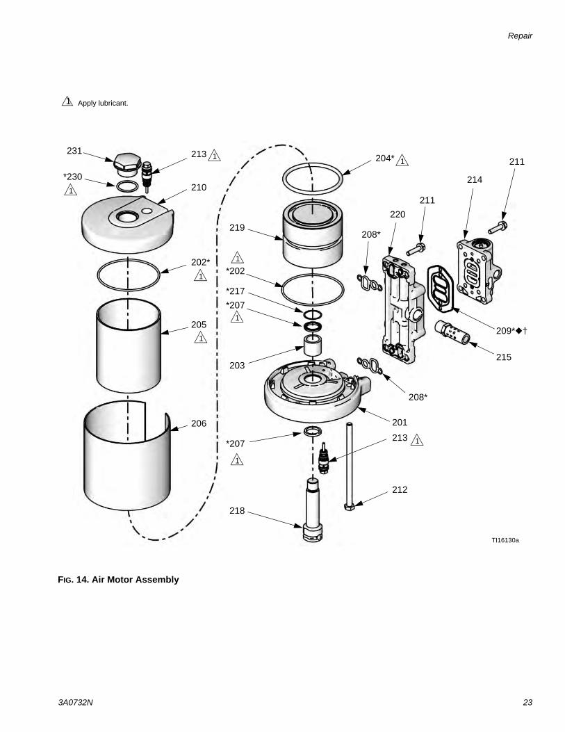
Disassemble the Air Motor1. See FIG. 14. Use a 10 mm socket wrench to remove
four screws (211). Remove the air valve (214) and gasket (209*†).
2. Remove four screws (211) and remove the manifold (220) and two gaskets (208*).
3. Use a 10 mm socket wrench to remove the pilot valves (213) from the top and bottom cover.
4. Use a 13 mm socket wrench to remove the tie bolts (212).
5. Remove the top cover (210). Remove the o-ring (202*). On 3.5 in. motors only, remove the plug (231) and o-ring (230*).
6. Remove the shield (206) and cylinder (205).
7. Remove the o-ring (204*) from the piston.
8. Secure the piston (219) in a vise with soft jaws. Use a wrench on the flats of the rod (218) to remove the rod and bottom cover assembly (201) from the pis-ton.
9. Remove the rod from the bottom cover assembly.
10. Remove retaining ring (217), u-cup seals (207*), and o-ring (202*) from the bottom cover.
Reassemble the Air MotorNOTE: For easier reassembly, start with the top cover (210) turned over on the workbench and assemble the air motor upside-down.
1. Lubricate and install the o-ring (202*) on the top cover (210).
2. Lubricate the inside of the cylinder (205). Lower the cylinder onto the top cover (210).
3. Install the shield (206) around the cylinder (205) and in the groove on the top cover (210).
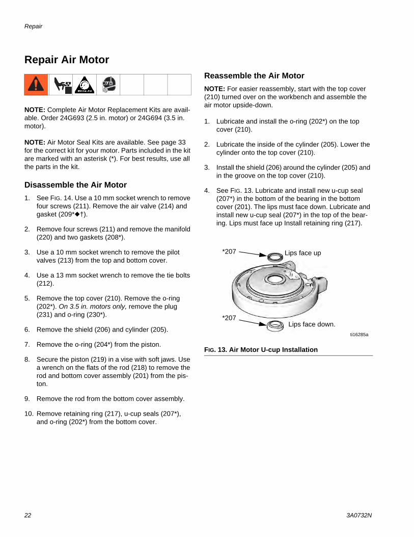
4. See FIG. 13. Lubricate and install new u-cup seal (207*) in the bottom of the bearing in the bottom cover (201). The lips must face down. Lubricate and install new u-cup seal (207*) in the top of the bear-ing. Lips must face up Install retaining ring (217).
FIG. 13. Air Motor U-cup Installation
*207
*207
ti16285a
Lips face up
Lips face down.
Repair
3A0732N 23
FIG. 14. Air Motor Assembly
TI16130a
201
215
214
213211
202*
203
204*
219
209*†
208*
*207
205
206
210
212
220
*202
208*
211
213
*217
218
*207
*230
231
1
1
1
1
1
1
1
1
Apply lubricant.1
1
Repair
24 3A0732N
5. Lubricate and install the o-ring (202*) on the bottom cover (201).
6. Carefully push the threaded end of the rod (218) up through the bottom cover (201).
7. Apply 16G561 adhesive to the threads of the rod (218). Screw the piston (219) onto the rod. Place the piston in a vise with soft jaws and torque to 35-40 ft-lb (47-54 N•m).
8. Lubricate and install the o-ring (204*) on the piston (219).
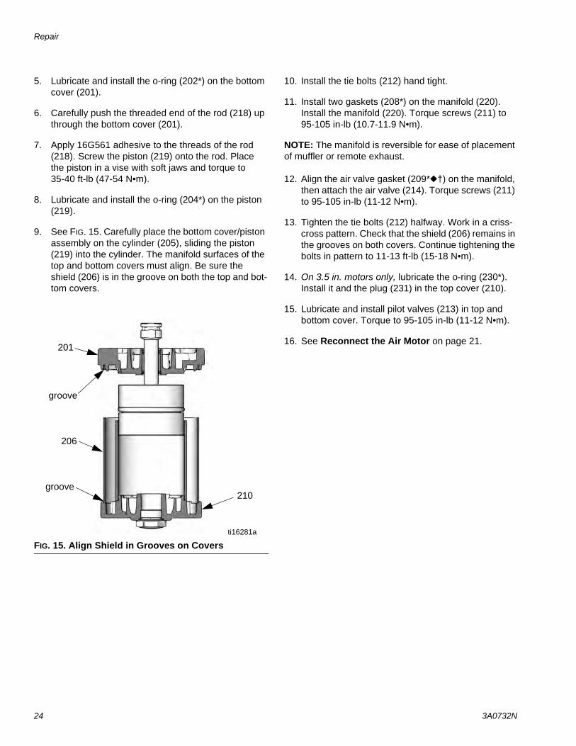
9. See FIG. 15. Carefully place the bottom cover/piston assembly on the cylinder (205), sliding the piston (219) into the cylinder. The manifold surfaces of the top and bottom covers must align. Be sure the shield (206) is in the groove on both the top and bot-tom covers.
10. Install the tie bolts (212) hand tight.
11. Install two gaskets (208*) on the manifold (220). Install the manifold (220). Torque screws (211) to 95-105 in-lb (10.7-11.9 N•m).
NOTE: The manifold is reversible for ease of placement of muffler or remote exhaust.
12. Align the air valve gasket (209*†) on the manifold, then attach the air valve (214). Torque screws (211) to 95-105 in-lb (11-12 N•m).
13. Tighten the tie bolts (212) halfway. Work in a criss-cross pattern. Check that the shield (206) remains in the grooves on both covers. Continue tightening the bolts in pattern to 11-13 ft-lb (15-18 N•m).
14. On 3.5 in. motors only, lubricate the o-ring (230*). Install it and the plug (231) in the top cover (210).
15. Lubricate and install pilot valves (213) in top and bottom cover. Torque to 95-105 in-lb (11-12 N•m).
16. See Reconnect the Air Motor on page 21.
FIG. 15. Align Shield in Grooves on Covers
groove
groove
201
206
ti16281a
210
Parts
3A0732N 25
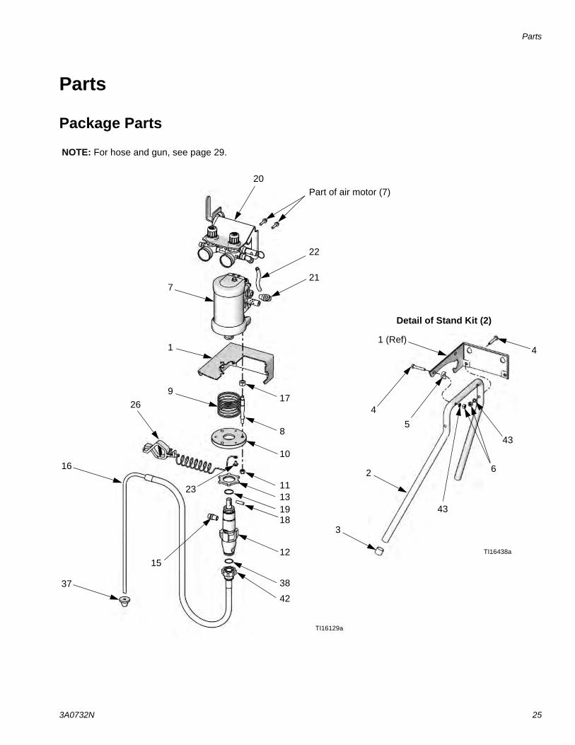
Parts
Package Parts
TI16129a
1
2313
16
21
11
42
19
17
18
9
8
7
10
15
20
37 38
22
26
Part of air motor (7)
NOTE: For hose and gun, see page 29.
12
2
3
4
5
6
Detail of Stand Kit (2)
43
43
41 (Ref)
TI16438a
Parts
26 3A0732N
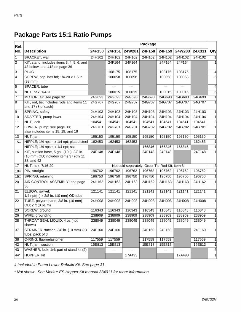
Package Parts 15:1 Ratio Pumps
‡ Included in Pump Lower Rebuild Kit. See page 31.
* Not shown. See Merkur ES Hopper Kit manual 334011 for more information.
Ref. No. Description
Package
Qty24F150 24F151 24W281 24F158 24F159 24W283 24X3111 BRACKET, wall 24H102 24H102 24H102 24H102 24H102 24H102 24H102 12 KIT, stand; includes items 3, 4, 5, 6, and
43 below, and 418 on page 3624F164 24F164 24F164 24F164 1
3 PLUG 108175 108175 108175 108175 44 SCREW, cap, hex hd; 1/4-20 x 1.5 in.
(38 mm)100058 100058 100058 100058 6
5 SPACER, tube --- --- --- --- 4
6 NUT, hex; 1/4-20 100015 100015 100015 100015 67 MOTOR, air; see page 32 24G693 24G693 24G693 24G693 24G693 24G693 24G693 18 KIT, rod, tie; includes rods and items 11
and 17 (3 of each)24G707 24G707 24G707 24G707 24G707 24G707 24G707 1
9 SPRING, safety 24H103 24H103 24H103 24H103 24H103 24H103 24H103 110 ADAPTER, pump lower 24H104 24H104 24H104 24H104 24H104 24H104 24H104 111 NUT, lock 104541 104541 104541 104541 104541 104541 104541 312 LOWER, pump; see page 30;
also includes items 15, 18, and 1924G701 24G701 24G701 24G702 24G702 24G702 24G701 1
13 NUT, jam 195150 195150 195150 195150 195150 195150 195150 115‡ NIPPLE; 1/4 npsm x 1/4 npt; plated steel 162453 162453 162453 162453 1
NIPPLE; 1/4 npsm x 1/4 npt; sst 166846 166846 166846 116 KIT, suction hose, 5 gal. (19 l); 3/8 in.
(10 mm) OD; includes items 37 (qty 1), 38, and 42
24F148 24F148 24F148 24F148 24F148 1
17 NUT, hex; 7/16-20 Not sold separately. Order Tie Rod Kit, item 8. 318‡ PIN, straight 196762 196762 196762 196762 196762 196762 196762 1
19‡ SPRING, retaining 196750 196750 196750 196750 196750 196750 196750 1
20 AIR CONTROL ASSEMBLY; see page 36
24H162 24H163 24H163 24H162 24H163 24H163 24H162 1
21 ELBOW, swivel; 1/4 npt(m) x 3/8 in. (10 mm) OD tube
121141 121141 121141 121141 121141 121141 121141 1
22 TUBE, polyurethane; 3/8 in. (10 mm) OD; 2 ft (0.61 m)
24H008 24H008 24H008 24H008 24H008 24H008 24H008 1
23 SCREW, ground 116343 116343 116343 116343 116343 116343 116343 126 WIRE, grounding 238909 238909 238909 238909 238909 238909 238909 128 THROAT SEAL LIQUID; 4 oz (not
shown)238049 238049 238049 238049 238049 238049 238049 1
37 STRAINER, suction; 3/8 in. (10 mm) OD tube; pack of 3
24F160 24F160 24F160 24F160 24F160 1
38 O-RING; fluoroelastomer 117559 117559 117559 117559 117559 142 NUT, jam, suction 15E813 15E813 15E813 15E813 15E813 143 WASHER, lock; 1/4; part of stand kit (2) --- --- --- --- 6
44* HOPPER, kit 17A493 17A493 1
Parts
3A0732N 27
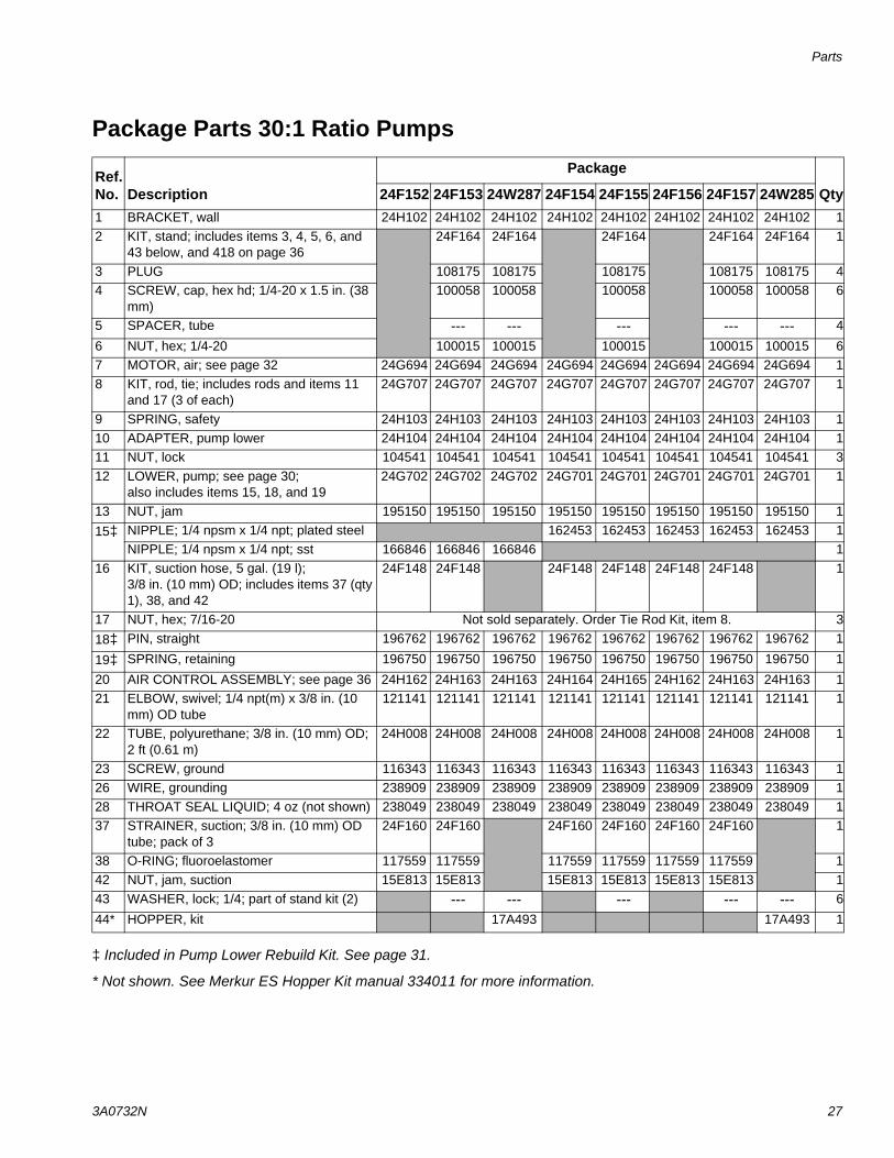
Package Parts 30:1 Ratio Pumps
‡ Included in Pump Lower Rebuild Kit. See page 31.
* Not shown. See Merkur ES Hopper Kit manual 334011 for more information.
Ref. No. Description
Package
Qty24F152 24F153 24W287 24F154 24F155 24F156 24F157 24W2851 BRACKET, wall 24H102 24H102 24H102 24H102 24H102 24H102 24H102 24H102 12 KIT, stand; includes items 3, 4, 5, 6, and
43 below, and 418 on page 3624F164 24F164 24F164 24F164 24F164 1
3 PLUG 108175 108175 108175 108175 108175 44 SCREW, cap, hex hd; 1/4-20 x 1.5 in. (38
mm)100058 100058 100058 100058 100058 6
5 SPACER, tube --- --- --- --- --- 4
6 NUT, hex; 1/4-20 100015 100015 100015 100015 100015 67 MOTOR, air; see page 32 24G694 24G694 24G694 24G694 24G694 24G694 24G694 24G694 18 KIT, rod, tie; includes rods and items 11
and 17 (3 of each)24G707 24G707 24G707 24G707 24G707 24G707 24G707 24G707 1
9 SPRING, safety 24H103 24H103 24H103 24H103 24H103 24H103 24H103 24H103 110 ADAPTER, pump lower 24H104 24H104 24H104 24H104 24H104 24H104 24H104 24H104 111 NUT, lock 104541 104541 104541 104541 104541 104541 104541 104541 312 LOWER, pump; see page 30;
also includes items 15, 18, and 1924G702 24G702 24G702 24G701 24G701 24G701 24G701 24G701 1
13 NUT, jam 195150 195150 195150 195150 195150 195150 195150 195150 115‡ NIPPLE; 1/4 npsm x 1/4 npt; plated steel 162453 162453 162453 162453 162453 1
NIPPLE; 1/4 npsm x 1/4 npt; sst 166846 166846 166846 116 KIT, suction hose, 5 gal. (19 l);
3/8 in. (10 mm) OD; includes items 37 (qty 1), 38, and 42
24F148 24F148 24F148 24F148 24F148 24F148 1
17 NUT, hex; 7/16-20 Not sold separately. Order Tie Rod Kit, item 8. 318‡ PIN, straight 196762 196762 196762 196762 196762 196762 196762 196762 1
19‡ SPRING, retaining 196750 196750 196750 196750 196750 196750 196750 196750 1
20 AIR CONTROL ASSEMBLY; see page 36 24H162 24H163 24H163 24H164 24H165 24H162 24H163 24H163 121 ELBOW, swivel; 1/4 npt(m) x 3/8 in. (10
mm) OD tube121141 121141 121141 121141 121141 121141 121141 121141 1
22 TUBE, polyurethane; 3/8 in. (10 mm) OD; 2 ft (0.61 m)
24H008 24H008 24H008 24H008 24H008 24H008 24H008 24H008 1
23 SCREW, ground 116343 116343 116343 116343 116343 116343 116343 116343 126 WIRE, grounding 238909 238909 238909 238909 238909 238909 238909 238909 128 THROAT SEAL LIQUID; 4 oz (not shown) 238049 238049 238049 238049 238049 238049 238049 238049 137 STRAINER, suction; 3/8 in. (10 mm) OD
tube; pack of 324F160 24F160 24F160 24F160 24F160 24F160 1
38 O-RING; fluoroelastomer 117559 117559 117559 117559 117559 117559 142 NUT, jam, suction 15E813 15E813 15E813 15E813 15E813 15E813 143 WASHER, lock; 1/4; part of stand kit (2) --- --- --- --- --- 6
44* HOPPER, kit 17A493 17A493 1
Parts
28 3A0732N
Parts
3A0732N 29
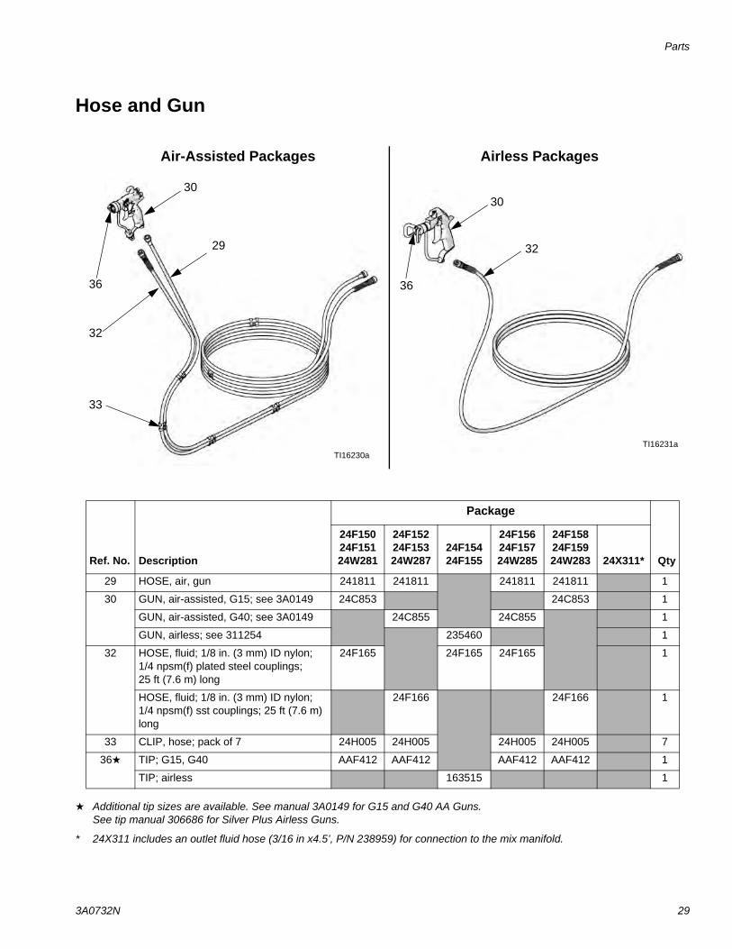
Hose and Gun
Additional tip sizes are available. See manual 3A0149 for G15 and G40 AA Guns. See tip manual 306686 for Silver Plus Airless Guns.
* 24X311 includes an outlet fluid hose (3/16 in x4.5’, P/N 238959) for connection to the mix manifold.
TI16230a
37
TI16231a
30
32
30
32
29
36 36
33
Air-Assisted Packages Airless Packages
Ref. No. Description
Package
Qty
24F15024F15124W281
24F15224F15324W287
24F15424F155
24F15624F15724W285
24F15824F15924W283 24X311*
29 HOSE, air, gun 241811 241811 241811 241811 1
30 GUN, air-assisted, G15; see 3A0149 24C853 24C853 1
GUN, air-assisted, G40; see 3A0149 24C855 24C855 1
GUN, airless; see 311254 235460 1
32 HOSE, fluid; 1/8 in. (3 mm) ID nylon; 1/4 npsm(f) plated steel couplings; 25 ft (7.6 m) long
24F165 24F165 24F165 1
HOSE, fluid; 1/8 in. (3 mm) ID nylon; 1/4 npsm(f) sst couplings; 25 ft (7.6 m) long
24F166 24F166 1
33 CLIP, hose; pack of 7 24H005 24H005 24H005 24H005 7
36 TIP; G15, G40 AAF412 AAF412 AAF412 AAF412 1
TIP; airless 163515 1
Parts
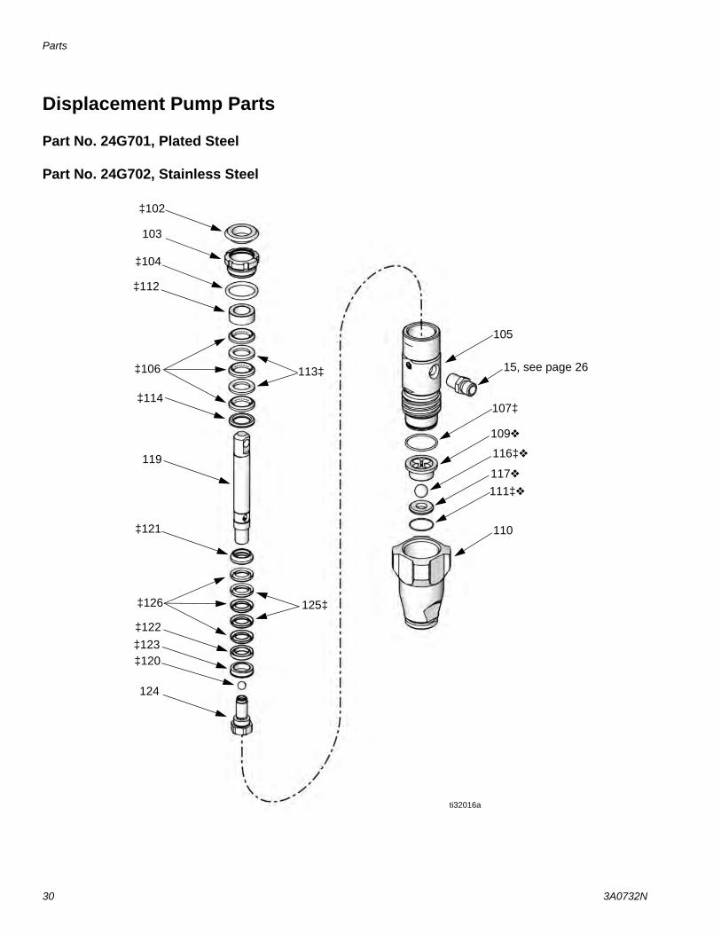
30 3A0732N
Displacement Pump Parts
Part No. 24G701, Plated Steel
Part No. 24G702, Stainless Steel
ti32016a
119
125‡
117
116‡
110
113‡
‡123
‡102
‡106
103
‡112
107‡
111‡
109
‡122
‡121
‡120
‡114
105
124
‡104
‡126
15, see page 26
Parts
3A0732N 31
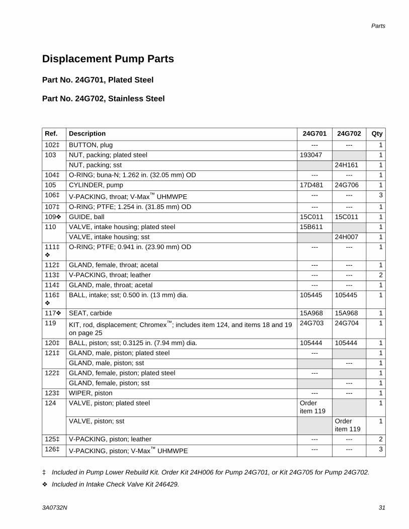
Displacement Pump Parts
Part No. 24G701, Plated Steel
Part No. 24G702, Stainless Steel
‡ Included in Pump Lower Rebuild Kit. Order Kit 24H006 for Pump 24G701, or Kit 24G705 for Pump 24G702.
Included in Intake Check Valve Kit 246429.
Ref. Description 24G701 24G702 Qty
102‡ BUTTON, plug --- --- 1103 NUT, packing; plated steel 193047 1
NUT, packing; sst 24H161 1104‡ O-RING; buna-N; 1.262 in. (32.05 mm) OD --- --- 1105 CYLINDER, pump 17D481 24G706 1106‡ V-PACKING, throat; V-Max™ UHMWPE --- --- 3
107‡ O-RING; PTFE; 1.254 in. (31.85 mm) OD --- --- 1109 GUIDE, ball 15C011 15C011 1110 VALVE, intake housing; plated steel 15B611 1
VALVE, intake housing; sst 24H007 1111‡
O-RING; PTFE; 0.941 in. (23.90 mm) OD --- --- 1
112‡ GLAND, female, throat; acetal --- --- 1113‡ V-PACKING, throat; leather --- --- 2114‡ GLAND, male, throat; acetal --- --- 1116‡
BALL, intake; sst; 0.500 in. (13 mm) dia. 105445 105445 1
117 SEAT, carbide 15A968 15A968 1119 KIT, rod, displacement; Chromex™; includes item 124, and items 18 and 19
on page 2524G703 24G704 1
120‡ BALL, piston; sst; 0.3125 in. (7.94 mm) dia. 105444 105444 1121‡ GLAND, male, piston; plated steel --- 1
GLAND, male, piston; sst --- 1122‡ GLAND, female, piston; plated steel --- 1
GLAND, female, piston; sst --- 1123‡ WIPER, piston --- --- 1124 VALVE, piston; plated steel Order
item 1191
VALVE, piston; sst Order item 119
1
125‡ V-PACKING, piston; leather --- --- 2126‡ V-PACKING, piston; V-Max™ UHMWPE --- --- 3

Parts
32 3A0732N
Air Motor Parts
Part No. 24G693, 2.5 in. (63.5 mm)
Part No. 24G694, 3.5 in. (88.9 mm), shown
TI16130a
201
215
214
213211
202*
203
204*
219
209*†
208*
*207
205
206
210
212
220
*202
208*
211
213
*217
218
*207
*230
231
Parts
3A0732N 33
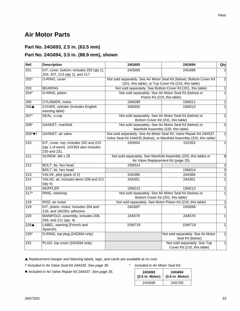
Air Motor Parts
Part No. 24G693, 2.5 in. (63.5 mm)
Part No. 24G694, 3.5 in. (88.9 mm), shown
Replacement Danger and Warning labels, tags, and cards are available at no cost.
† Included in Air Valve Seal Kit 24A535. See page 35.
Included in Air Valve Repair Kit 24A537. See page 35.
* Included in Air Motor Seal Kit:
Ref. Description 24G693 24G694 Qty201 KIT, cover, bottom; includes 202 (qty 1),
203, 207, 213 (qty 1), and 21724G695 24G696 1
202* O-RING, cover Not sold separately. See Air Motor Seal Kit (below), Bottom Cover Kit (201, this table), or Top Cover Kit (210, this table)
2
203 BEARING Not sold separately. See Bottom Cover Kit (201, this table) 1204* O-RING, piston Not sold separately. See Air Motor Seal Kit (below) or
Piston Kit (219, this table)1
205 CYLINDER, motor 15M289 15M211 1206 COVER, cylinder (includes English
warning label)15M302 15M212 1
207* SEAL, u-cup Not sold separately. See Air Motor Seal Kit (below) orBottom Cover Kit (201, this table)
2
208* GASKET, manifold Not sold separately. See Air Motor Seal Kit (below) orManifold Assembly (220, this table)
2
209*† GASKET, air valve Not sold separately. See Air Motor Seal Kit, Valve Repair Kit 24A537, Valve Seal Kit 24A535 (below), or Manifold Assembly (220, this table)
1
210 KIT, cover, top; includes 202 and 213 (qty 1 of each). 15X353 also includes 230 and 231.
24H004 15X353 1
211 SCREW, M6 x 25 Not sold separately. See Manifold Assembly (220, this table) or Air Valve Replacement Kit (page 35)
8
212 BOLT, tie, hex head 15M314 2BOLT, tie, hex head 15M314 3
213 VALVE, pilot (pack of 2) 24A366 24A366 1214 VALVE, air; includes items 209 and 211
(qty 4)24A351 24A351 1
215 MUFFLER 15M213 15M213 1217* RING, retaining Not sold separately. See Air Motor Seal Kit (below) or
Bottom Cover Kit (201, this table)1
218 ROD, air motor Not sold separately. See Motor Piston Kit (219, this table) 1219 KIT, piston, motor; includes 204 and
218, and 16G561 adhesive.24G697 24G698 1
220 MANIFOLD, assembly, includes 208, 209, and 211 (qty. 4)
24A579 24A579 1
229 LABEL, warning (French and Spanish)
15W719 15W719 1
230* O-RING, top plug (24G694 only) Not sold separately. See Air Motor Seal Kit (below)
1
231 PLUG, top cover (24G694 only) Not sold separately. See Top Cover Kit (210, this table)
1
24G693 (2.5 in. Motor)
24G694 (3.5 in. Motor)
24G699 24G700
Parts
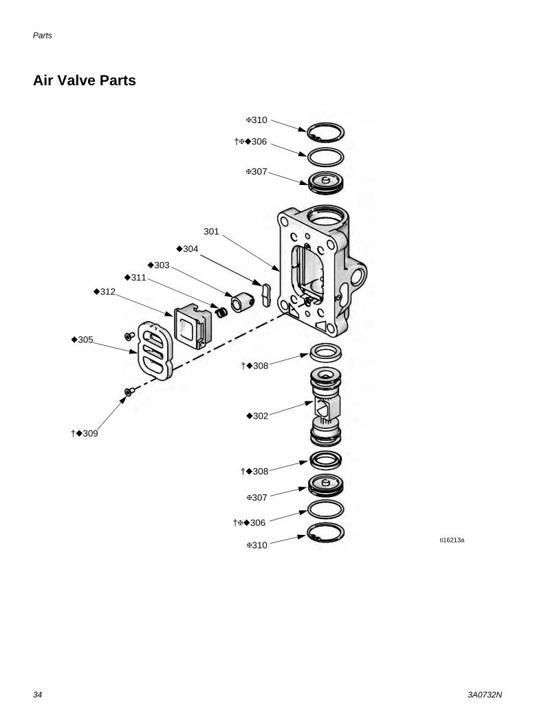
34 3A0732N
Air Valve Parts
310
307
307
†309
305
312
311303
302
†308
†308
301
304
310ti16213a
†306
†306

Parts
3A0732N 35
Air Valve Parts
Complete Air Valve Replacement Kit 24A351To replace the complete air valve, order Air Valve Replacement Kit 24A351. The kit includes items 301-312 below, and items 209 and 211 on page 33.
Air Valve Repair KitsAir valve parts are not sold individually. The table below shows possible kit options for each part.
† Included in Air Valve Seal Kit 24A535.
Included in Air Valve Repair Kit 24A537.
Included in Air Valve End Cap Kit 24A360.
Replacement screws (309) are available in a pack of 10. Order Kit 24A359.
Ref. DescriptionQty
.
Air Valve Repair Kit
24A537
Air ValveSeal Kit 24A535
Air ValveEnd Cap Kit
24A360301 HOUSING 1302 AIR VALVE PISTON 1
303 DETENT PISTON ASSEMBLY 1
304 DETENT CAM 1
305 PLATE, air valve 1
306† O-RING 2
307 CAP 2
308† U-CUP 2
309† SCREW 2
310 SNAP RING 2
311 DETENT SPRING 1
312 CUP 1
Parts
36 3A0732N
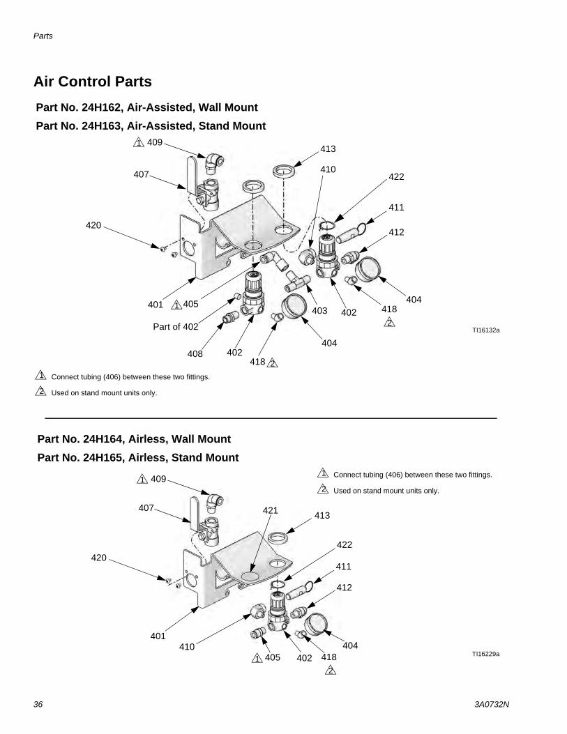
Air Control Parts
TI16132a
404
420
401
402
403 402405 404
407
408
409
410
411
412
413
Part of 402
1
Connect tubing (406) between these two fittings.
Used on stand mount units only.
1
2
1
Part No. 24H162, Air-Assisted, Wall Mount
Part No. 24H163, Air-Assisted, Stand Mount
Part No. 24H164, Airless, Wall Mount
Part No. 24H165, Airless, Stand Mount
TI16229a
420
402405404
407
409
410
411
412
413
1
1
Connect tubing (406) between these two fittings.
Used on stand mount units only.
1
2
401
418
418
4182
2
2
421
422
422
Parts
3A0732N 37
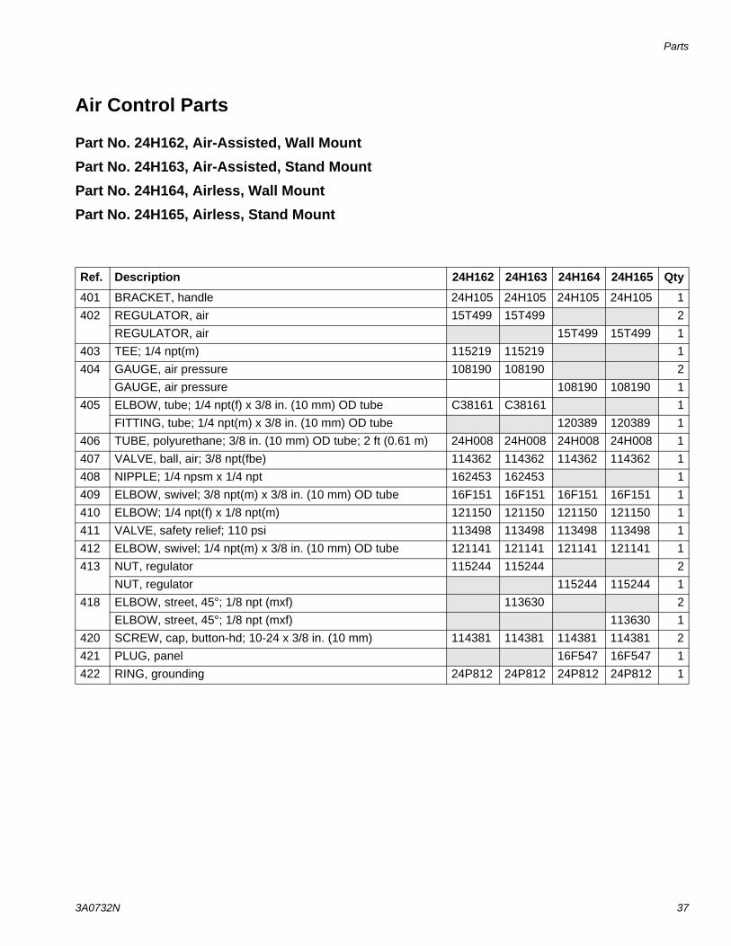
Air Control Parts
Part No. 24H162, Air-Assisted, Wall Mount
Part No. 24H163, Air-Assisted, Stand Mount
Part No. 24H164, Airless, Wall Mount
Part No. 24H165, Airless, Stand Mount
Ref. Description 24H162 24H163 24H164 24H165 Qty
401 BRACKET, handle 24H105 24H105 24H105 24H105 1402 REGULATOR, air 15T499 15T499 2
REGULATOR, air 15T499 15T499 1403 TEE; 1/4 npt(m) 115219 115219 1404 GAUGE, air pressure 108190 108190 2
GAUGE, air pressure 108190 108190 1405 ELBOW, tube; 1/4 npt(f) x 3/8 in. (10 mm) OD tube C38161 C38161 1
FITTING, tube; 1/4 npt(m) x 3/8 in. (10 mm) OD tube 120389 120389 1406 TUBE, polyurethane; 3/8 in. (10 mm) OD tube; 2 ft (0.61 m) 24H008 24H008 24H008 24H008 1407 VALVE, ball, air; 3/8 npt(fbe) 114362 114362 114362 114362 1408 NIPPLE; 1/4 npsm x 1/4 npt 162453 162453 1409 ELBOW, swivel; 3/8 npt(m) x 3/8 in. (10 mm) OD tube 16F151 16F151 16F151 16F151 1410 ELBOW; 1/4 npt(f) x 1/8 npt(m) 121150 121150 121150 121150 1411 VALVE, safety relief; 110 psi 113498 113498 113498 113498 1412 ELBOW, swivel; 1/4 npt(m) x 3/8 in. (10 mm) OD tube 121141 121141 121141 121141 1413 NUT, regulator 115244 115244 2
NUT, regulator 115244 115244 1418 ELBOW, street, 45°; 1/8 npt (mxf) 113630 2
ELBOW, street, 45°; 1/8 npt (mxf) 113630 1420 SCREW, cap, button-hd; 10-24 x 3/8 in. (10 mm) 114381 114381 114381 114381 2421 PLUG, panel 16F547 16F547 1422 RING, grounding 24P812 24P812 24P812 24P812 1
Kits and Accessories
38 3A0732N
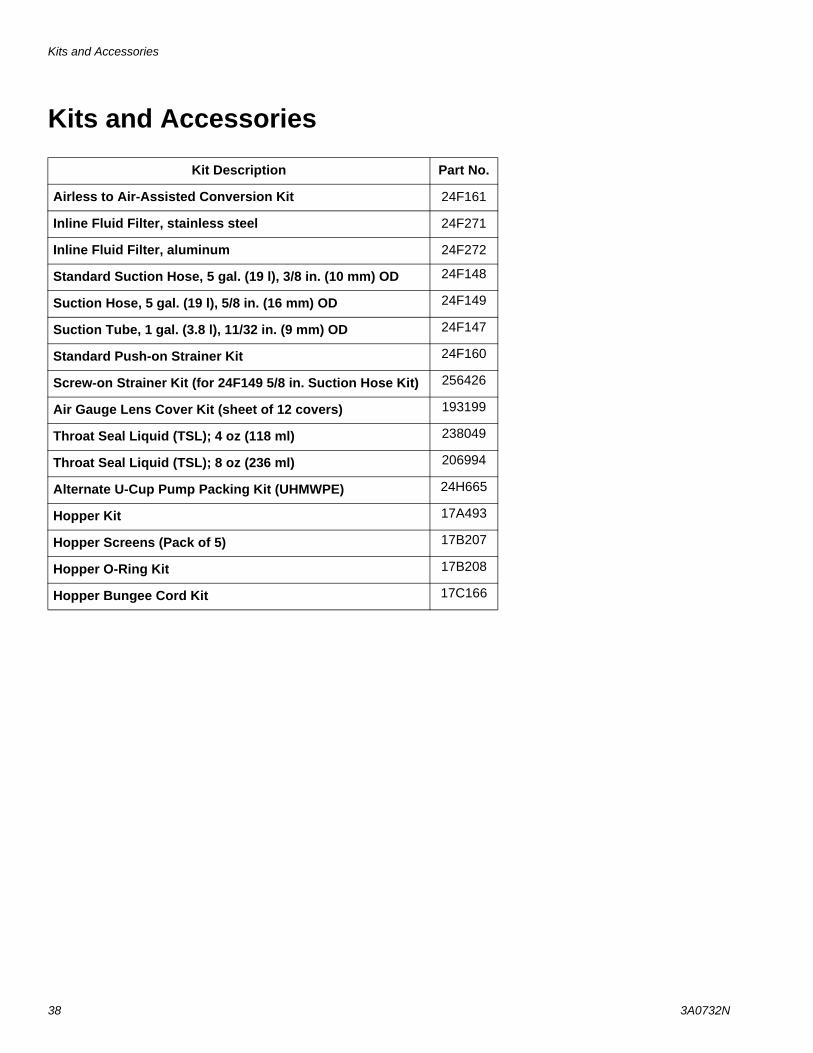
Kits and Accessories
Kit Description Part No.
Airless to Air-Assisted Conversion Kit 24F161
Inline Fluid Filter, stainless steel 24F271
Inline Fluid Filter, aluminum 24F272
Standard Suction Hose, 5 gal. (19 l), 3/8 in. (10 mm) OD 24F148
Suction Hose, 5 gal. (19 l), 5/8 in. (16 mm) OD 24F149
Suction Tube, 1 gal. (3.8 l), 11/32 in. (9 mm) OD 24F147
Standard Push-on Strainer Kit 24F160
Screw-on Strainer Kit (for 24F149 5/8 in. Suction Hose Kit) 256426
Air Gauge Lens Cover Kit (sheet of 12 covers) 193199
Throat Seal Liquid (TSL); 4 oz (118 ml) 238049
Throat Seal Liquid (TSL); 8 oz (236 ml) 206994
Alternate U-Cup Pump Packing Kit (UHMWPE) 24H665
Hopper Kit 17A493
Hopper Screens (Pack of 5) 17B207
Hopper O-Ring Kit 17B208
Hopper Bungee Cord Kit 17C166
Package Dimensions
3A0732N 39
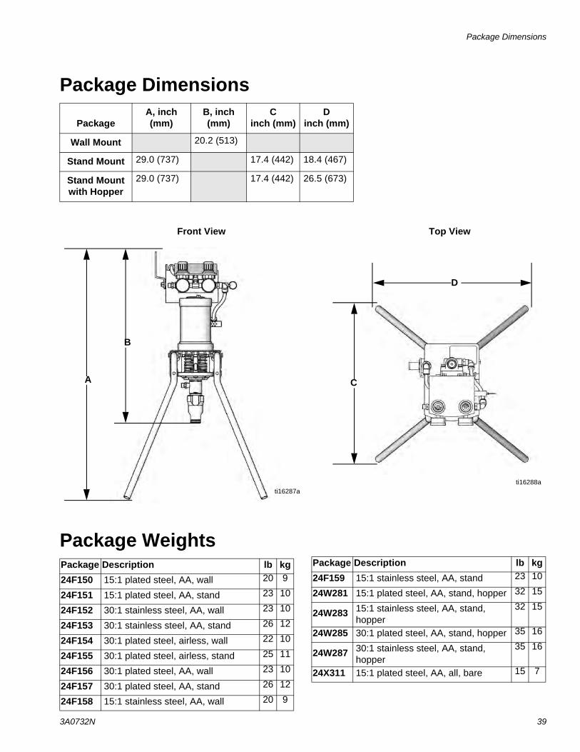
Package Dimensions
Package Weights
PackageA, inch (mm)
B, inch (mm)
Cinch (mm)
Dinch (mm)
Wall Mount 20.2 (513)
Stand Mount 29.0 (737) 17.4 (442) 18.4 (467)
Stand Mount with Hopper
29.0 (737) 17.4 (442) 26.5 (673)
ti16287a
A
B
ti16288a
C
D
Front View Top View
Package Description lb kg24F150 15:1 plated steel, AA, wall 20 9
24F151 15:1 plated steel, AA, stand 23 10
24F152 30:1 stainless steel, AA, wall 23 10
24F153 30:1 stainless steel, AA, stand 26 12
24F154 30:1 plated steel, airless, wall 22 10
24F155 30:1 plated steel, airless, stand 25 11
24F156 30:1 plated steel, AA, wall 23 10
24F157 30:1 plated steel, AA, stand 26 12
24F158 15:1 stainless steel, AA, wall 20 9
24F159 15:1 stainless steel, AA, stand 23 10
24W281 15:1 plated steel, AA, stand, hopper 32 15
24W283 15:1 stainless steel, AA, stand, hopper
32 15
24W285 30:1 plated steel, AA, stand, hopper 35 16
24W287 30:1 stainless steel, AA, stand, hopper
35 16
24X311 15:1 plated steel, AA, all, bare 15 7
Package Description lb kg
Wall Bracket Mounting Hole Diagram
40 3A0732N
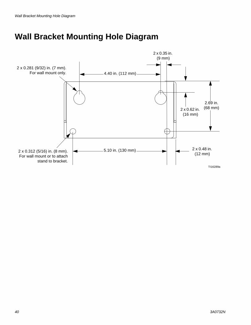
Wall Bracket Mounting Hole Diagram
2 x 0.281 (9/32) in. (7 mm).For wall mount only.
TI16289a
4.40 in. (112 mm)
2 x 0.312 (5/16) in. (8 mm).For wall mount or to attach
stand to bracket.
5.10 in. (130 mm)
2.69 in. (68 mm)
2 x 0.48 in. (12 mm)
2 x 0.62 in. (16 mm)
2 x 0.35 in. (9 mm)
Technical Data
3A0732N 41
Technical Data
* Sound power at 70 psi (0.48 MPa, 4.8 bar), 80 cpm. Sound power measured per ISO-9614-2.
** Sound pressure was tested 3.28 feet (1 m) from equipment.
Maximum fluid working pressure15:1 Pumps. . . . . . . . . . . . . . . . . . . . . . . . . . . . 30:1 Pumps. . . . . . . . . . . . . . . . . . . . . . . . . . . .
1500 psi (10.3 MPa, 103 bar)3000 psi (20.7 MPa, 207 bar)
Maximum air inlet pressure . . . . . . . . . . . . . . . . . . . 100 psi (0.7 MPa, 7.0 bar)
Ratio . . . . . . . . . . . . . . . . . . . . . . . . . . . . . . . . . . . . 15:1 or 30:1 (see Models, page 3)
Maximum fluid temperature. . . . . . . . . . . . . . . . . . . 160°F, 71°C
Ambient air temperature range . . . . . . . . . . . . . . . . 35-120°F, 2-49°CPackage air inlet size . . . . . . . . . . . . . . . . . . . . . . . 3/8 npt(f)Package fluid outlet size . . . . . . . . . . . . . . . . . . . . . 1/4 npsm(m)Maximum motor speed . . . . . . . . . . . . . . . . . . . . . . (Do not exceed maximum recommended speed of fluid pump, to prevent premature pump wear.)
240 cycles per minute
Maximum spray tip orifice size . . . . . . . . . . . . . . . . .019 in. (0.483 mm)Sound data
24G693 Air MotorSound power* . . . . . . . . . . . . . . . . . . . . . . .Sound pressure**. . . . . . . . . . . . . . . . . . . . .
83.2 dBA76.5 dBA
24G694 Air MotorSound power* . . . . . . . . . . . . . . . . . . . . . . .Sound pressure**. . . . . . . . . . . . . . . . . . . . .
84.5 dBA77.9 dBA
Wetted partsPlated steel pumps . . . . . . . . . . . . . . . . . . . . . . Stainless steel, nickel plated carbon steel, tungsten
carbide, ptfe, acetal, leather, ultra-high molecular weight polyethylene
Stainless steel pumps . . . . . . . . . . . . . . . . . . . . Stainless steel, tungsten carbide, ptfe, acetal, leather, ultra-high molecular weight polyethylene
Spray guns . . . . . . . . . . . . . . . . . . . . . . . . . . . . . See manual 3A0149 (G15 and G40 AA guns) or 311254 (Silver Plus airless gun)
Fluid hose. . . . . . . . . . . . . . . . . . . . . . . . . . . . . . Nylon, plated or stainless steelSuction assembly . . . . . . . . . . . . . . . . . . . . . . . . Stainless steel, nylon, acetal, fluoroelastomer,
polyethylene
Performance Charts
42 3A0732N
Performance Charts
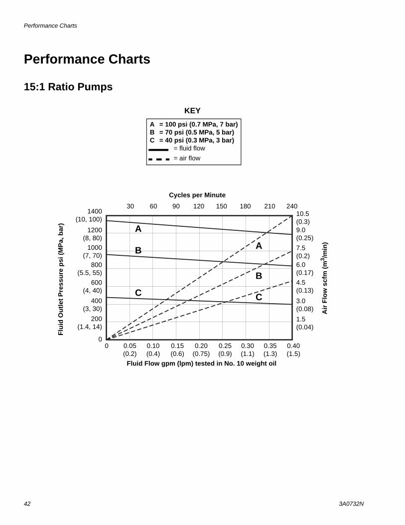
15:1 Ratio Pumps
A = 100 psi (0.7 MPa, 7 bar)B = 70 psi (0.5 MPa, 5 bar)C = 40 psi (0.3 MPa, 3 bar)
= fluid flow= air flow
A
B
C
A
B
C
30 60 90 120 150 180 210
Cycles per Minute
Air
Flo
w s
cfm
(m3 /
min
)
Flui
d O
utle
t Pre
ssur
e ps
i (M
Pa,
bar
)
Fluid Flow gpm (lpm) tested in No. 10 weight oil
KEY
24010.5 (0.3)
1400(10, 100)
0.05(0.2)
9.0 (0.25)7.5 (0.2)6.0 (0.17)4.5 (0.13)
3.0 (0.08)
1.5 (0.04)
0.15(0.6)
0.10(0.4)
0.20(0.75)
0.25(0.9)
0.30(1.1)
0.35(1.3)
0.40(1.5)
1200(8, 80)
1000(7, 70)
800(5.5, 55)
600(4, 40)
400(3, 30)
200(1.4, 14)
00
Performance Charts
3A0732N 43
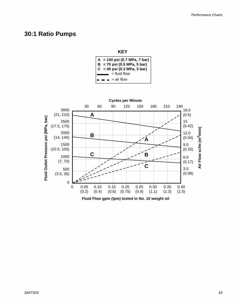
30:1 Ratio Pumps
A = 100 psi (0.7 MPa, 7 bar)B = 70 psi (0.5 MPa, 5 bar)C = 40 psi (0.3 MPa, 3 bar)
= fluid flow= air flow
A
B
C
A
B
C
Cycles per Minute
Air
Flo
w s
cfm
(m3 /
min
)
Flui
d O
utle
t Pre
ssur
e ps
i (M
Pa,
bar
)
Fluid Flow gpm (lpm) tested in No. 10 weight oil
KEY
30 60 90 120 150 180 210 240
0.05(0.2)
0.15(0.6)
0.10(0.4)
0.20(0.75)
0.25(0.9)
0.30(1.1)
0.35(1.3)
0.40(1.5)
0
18.0 (0.5)
3000(21, 210)
9.0 (0.25)
15 (0.42)
12.0 (0.34)
6.0 (0.17)
3.0 (0.08)
2500(17.5, 175)
2000(14, 140)
1500(10.5, 105)
1000(7, 70)
500(3.5, 35)
0
All written and visual data contained in this document reflects the latest product information available at the time of publication. Graco reserves the right to make changes at any time without notice.
Original instructions. This manual contains English. MM 3A0732
Graco Headquarters: MinneapolisInternational Offices: Belgium, China, Japan, Korea
GRACO INC. AND SUBSIDIARIES • P.O. BOX 1441 • MINNEAPOLIS MN 55440-1441 • USA
Copyright 2010, Graco Inc. All Graco manufacturing locations are registered to ISO 9001.www.graco.com
Revision N, August 2017
Graco Standard WarrantyGraco warrants all equipment referenced in this document which is manufactured by Graco and bearing its name to be free from defects in material and workmanship on the date of sale to the original purchaser for use. With the exception of any special, extended, or limited warranty published by Graco, Graco will, for a period of twelve months from the date of sale, repair or replace any part of the equipment determined by Graco to be defective. This warranty applies only when the equipment is installed, operated and maintained in accordance with Graco’s written recommendations.
This warranty does not cover, and Graco shall not be liable for general wear and tear, or any malfunction, damage or wear caused by faulty installation, misapplication, abrasion, corrosion, inadequate or improper maintenance, negligence, accident, tampering, or substitution of non-Graco component parts. Nor shall Graco be liable for malfunction, damage or wear caused by the incompatibility of Graco equipment with structures, accessories, equipment or materials not supplied by Graco, or the improper design, manufacture, installation, operation or maintenance of structures, accessories, equipment or materials not supplied by Graco.
This warranty is conditioned upon the prepaid return of the equipment claimed to be defective to an authorized Graco distributor for verification of the claimed defect. If the claimed defect is verified, Graco will repair or replace free of charge any defective parts. The equipment will be returned to the original purchaser transportation prepaid. If inspection of the equipment does not disclose any defect in material or workmanship, repairs will be made at a reasonable charge, which charges may include the costs of parts, labor, and transportation.
THIS WARRANTY IS EXCLUSIVE, AND IS IN LIEU OF ANY OTHER WARRANTIES, EXPRESS OR IMPLIED, INCLUDING BUT NOT LIMITED TO WARRANTY OF MERCHANTABILITY OR WARRANTY OF FITNESS FOR A PARTICULAR PURPOSE.
Graco’s sole obligation and buyer’s sole remedy for any breach of warranty shall be as set forth above. The buyer agrees that no other remedy (including, but not limited to, incidental or consequential damages for lost profits, lost sales, injury to person or property, or any other incidental or consequential loss) shall be available. Any action for breach of warranty must be brought within two (2) years of the date of sale.
GRACO MAKES NO WARRANTY, AND DISCLAIMS ALL IMPLIED WARRANTIES OF MERCHANTABILITY AND FITNESS FOR A PARTICULAR PURPOSE, IN CONNECTION WITH ACCESSORIES, EQUIPMENT, MATERIALS OR COMPONENTS SOLD BUT NOT MANUFACTURED BY GRACO. These items sold, but not manufactured by Graco (such as electric motors, switches, hose, etc.), are subject to the warranty, if any, of their manufacturer. Graco will provide purchaser with reasonable assistance in making any claim for breach of these warranties.
In no event will Graco be liable for indirect, incidental, special or consequential damages resulting from Graco supplying equipment hereunder, or the furnishing, performance, or use of any products or other goods sold hereto, whether due to a breach of contract, breach of warranty, the negligence of Graco, or otherwise.
FOR GRACO CANADA CUSTOMERSThe Parties acknowledge that they have required that the present document, as well as all documents, notices and legal proceedings entered into, given or instituted pursuant hereto or relating directly or indirectly hereto, be drawn up in English. Les parties reconnaissent avoir convenu que la rédaction du présente document sera en Anglais, ainsi que tous documents, avis et procédures judiciaires exécutés, donnés ou intentés, à la suite de ou en rapport, directement ou indirectement, avec les procédures concernées.
Graco InformationFor the latest information about Graco products, visit www.graco.com.
For patent information, see www.graco.com/patents.
TO PLACE AN ORDER, contact your Graco distributor or call to identify the nearest distributor.Phone: 612-623-6921 or Toll Free: 1-800-328-0211 Fax: 612-378-3505