mergen: nesting software for steel manufacturing · pdf filemergen: nesting software for steel...
TRANSCRIPT
MERGEN: Nesting Software for Steel Manufacturing
Mehmet KAPAR
Mka Software and Engineering Services Ltd.
A. INTRODUCTION:
Steel structure manufacturers have preferred:
BIM (Building Information Modelling) softwares while designing their structures,
Several types of machines for cutting of the structural members,
And well-educated labor force for rapid, qualified and economic steel structure.
Via our developed software Mergen, we research the ways of manufacturing more economically
and using the machines more productively.
In this paper we examined the bottlenecks of the steel manufacturing and explained that to which
bottlenecks can be solved via Mergen.
B. CHALLENGES IN MANUFACTURING STEEL STRUCTURES:
1. Bottlenecks on cutting and drilling stages
The steel structures are modelled by using BIM softwares such as Tekla Structures, Advance Steel
etc. These structure are manufactured by technical drawing manually or via CNC machines. It has
been that the CNC machines are used for rapid, accurate and economic manufacturing.
The main stages in the manufacturing of the steel structures, are designing the structure, supplying
the material, cutting and drilling, assembling and erection. The minimizing wasted and remnant
parts in the cutting and drilling stage, enables to f inish the structure economically. Thereby, the
cutting the steel structure’s members should be planned carefully. The quality of the cutting plans
done by technical office, is related to wasted, remnant parts and the time spent.
Generally the steel structures consist of 15% steel plates and 85% profiles. In the market there are
lots of 2-D optimization softwares for plate cutting. Primarily, we are focused on profile cutting the
85% parts of the structures. To get optimum solution for profile cutting the following methods has
been used:
a. To work with the best stock length:
In this method, the stock length that minimizes the amount of the wasted and remnant parts
amount, is determined. The best stock length can be found by operating a good bar nesting
algorithm with different stock lengths. However getting the steel profiles with the custom
stock length is not easy. Firstly the steel profiles manufacturer company must be in
manufacturing planning phase, secondly it needs 3-4 months to wait and finally the order
must be over the some amounts. This method is feasible only in huge projects.
b. To cut the constant stock length by combining the projects:
In this method, the same steel profiles in different projects are cut in the same cutting plan. If
the parts have large and small lengths, the good results would be reachable. This method
needs barcoding and tracing the cutting parts, unbundling for each project after cutting,
serious planning and management. This method is applicable for the huge manufacturer
companies with the support of a manufacture planning software.
c. To make splices with the remnant parts remains after cutting the constant stock length:
This method is especially used for reducing the wasted and remnant parts of the profiles which
are rarely encountered in the projects. As the cutting plans with the splices of the profiles
cannot be done by a standard 1-D bar nesting algorithms, they are made by technical office
manually. The issues below must be taken into consideration in the splice planning:
There can’t be more than one splice on a part,
Only the parts longer than a specific length can be used for splices,
Splice location must be far enough from the bolt holes and the welded parts on the profiles.
The analysis of the welded splice or the bolted splice connection must be done.
For resistance, stability and preventing possible clashes, taking these issues into consideration
abolishes the possible problems in the future.
The ability of the person who plans the cutting, the prescribed time to him, the number of the
part that will be cut and the required splice count after planning affects the quality of the cutting
plan.
The cutting and drilling CNC machines use the NC files that are taken from BIM softwares. If
there is a splice on the part, the machine operator must create the cutting information by using the
NC file belongs to the whole part manually. In this case the faults of the operator can cause serious
costs. Moreover, the wrong selection of the splice point by the technical office causes defective
manufacturing. The operator must notice and fix it. This is another burden for him.
2. Bottlenecks on the part counts in NC file content
In some cases, for example manufacturing only 2 floors of 5-floor-building or selected parts, it has
been faced that IFC model and the parts’ count in the NC files couldn’t match with each other. It
needs fixing the parts’ count in the NC files based on IFC model. A person planning to manufacture
by using the count information in the NC files cannot manage the process manually in big projects.
3. Bottlenecks on tube cutting via oxy-plasma
Another problem related to the manufacturing the steel structure is the cutting the tubes. Tubes
are cut by oxy-plasma tube cutting machines or laser plasma tube cutting machines. Oxy-plasma
machine with tube cutting kit uses DXF files including cutting places determined by the catenaries
identified as polygon. For increasing the manufacturing rate, the polygon needs to be simplified
because of the stopping on each polygon point creates the catenary. This process takes serious
time to cut with oxy-plasma in the projects that has many tubes to be cut.
4. Bottlenecks on tube cutting via laser tube cutting machine
The tube shall be cut with the laser-tube cutting machines can be identified by the user manually.
There are many tube design softwares for this purpose. But the most practical way for a project,
that has the IFC, file is saving the tubes one by one. Planning and managing the cutting process
takes serious in the projects that consist of many tubes.
To prepare data for the oxy-plasma or the laser-plasma tube cutting machines can be done barely
in the case that the tubes has no splice. It gets a lot more complex if the tubes have splices.

5. Bottlenecks on steel plate cutting via oxy-plasma
As it mentioned therein before that steel plate has 15% weight of the steel structures. In the multi-
storey car park project that is solved at annex, it has steel plates which includes 23845 count, in 568
different dimensions and has 115 tones weight. The parameters such as plate’s thickness, steel
grade and if the plate has bolt holes or not, determine the sheet that will be used and the machine
that will process.
The steel sheets can be procured in several dimensions in the market. For finding the best solution
for answering which dimensions of steel sheet and counts the project will need, there are some 2-D
nesting softwares. But they are not preferred because of the using them takes plenty of time.
C. THE SOLUTION OF MKA SOFTWARE : MERGEN
Let us take the NC files on DSTV standard from the structure model designed by using BIM
((Tekla Structures or Advance Steel) softwares and IFC file includes the structural member
information (part, assembly part, 3D geometrical information).
Figure 1. Loading IFC and NC1 files which were taken from Tekla Structures.
Let us group the NC files for each processing machine, steel grade and profile name. Now we
know which parts shall be optimized with one or two dimensional nesting algorithm
Figure 2. Grouping the parts for each processing machine.

Let us load the IFC file and control the part information on 3D model and part counts placed in
NC files. It can be faced on the special cases such as manufacturing only 2 floors of 5-floor-
building or selected parts. In those cases IFC model and the parts’ count in the NC files couldn’t
match with each other. Mergen finds and fixes it.
Figure 3. An example for a half project.
Let us enter the previous projects’ remnant into the system for profile optimization, and in this
way put the remnant parts in the junkyards to good use by splicing them.
Figure 4. Entering old remnant parts.
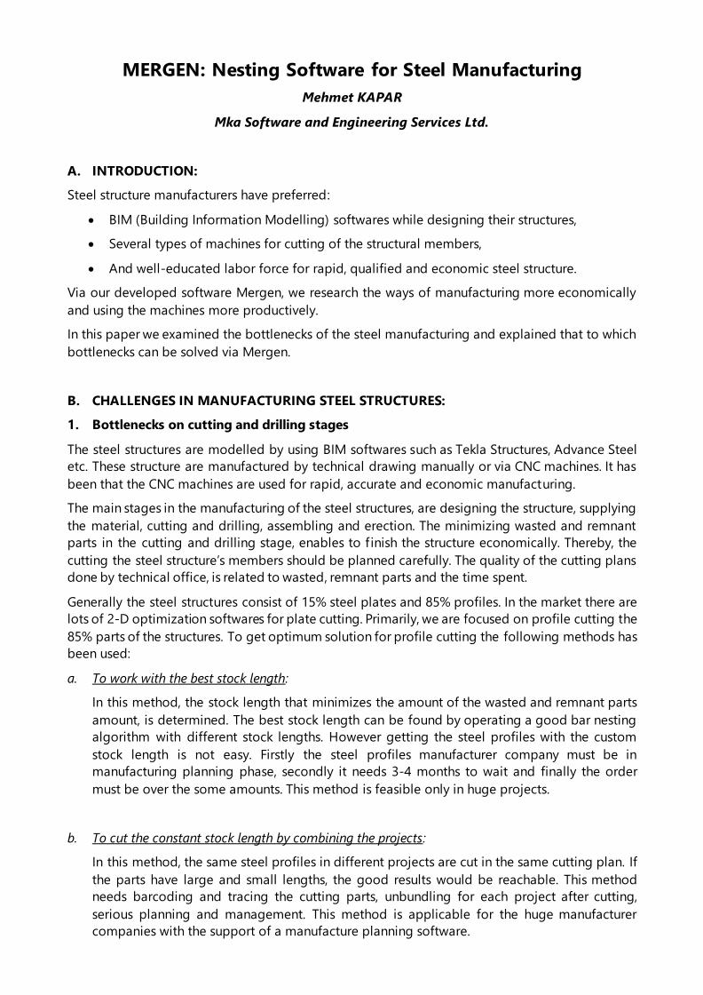
Let us prepare the best cutting plans with the least waste and splices by taking the rules of
making splices mentioned therein before into consideration.
Figure 5. Cutting plans for steel profiles and the part which consists splice.
Let us show splice locations on 3-D structural model. You can check if the splice locations are
the correct places (far enough from bolt holes and the other welded parts) or not.
Figure 6. Reds are the part with splice, greens are the splice location on the part.
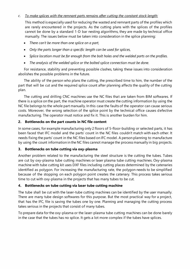
Let us folder the NC files (original files for the parts without splices, the new files produced by
us for the parts with splices) belongs to the profiles that will be processed on the cutting and
drilling machine sequentially according to the cutting plans. Thus minimize possibility of
making a mistake of the operator.
Figure 7. Cutting plan folders for HEB500 and NC files for first cutting plan.
Figure 8.
Extra features for tube cutting:
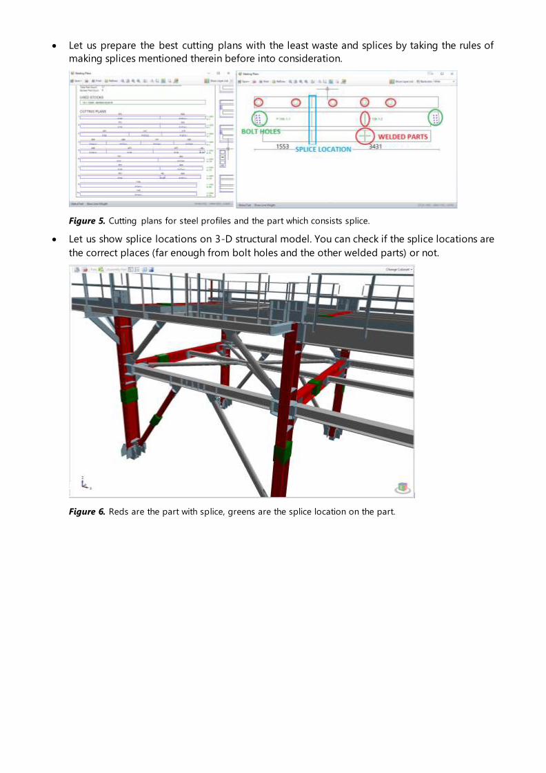
Let us prepare cutting plan for the tubes. If it has splice split the polygon in the NC file and
bring order and speed by saving the cutting plans as DXF for the oxy-plasma tube cutting
machine.
Let us simplify the polygon points that describe the fishmount cutting for the oxy-plasma tube
cutting machine. So the machine works faster.
Figure 9. Preparing the cutting plan DXF files for oxy-plasma.
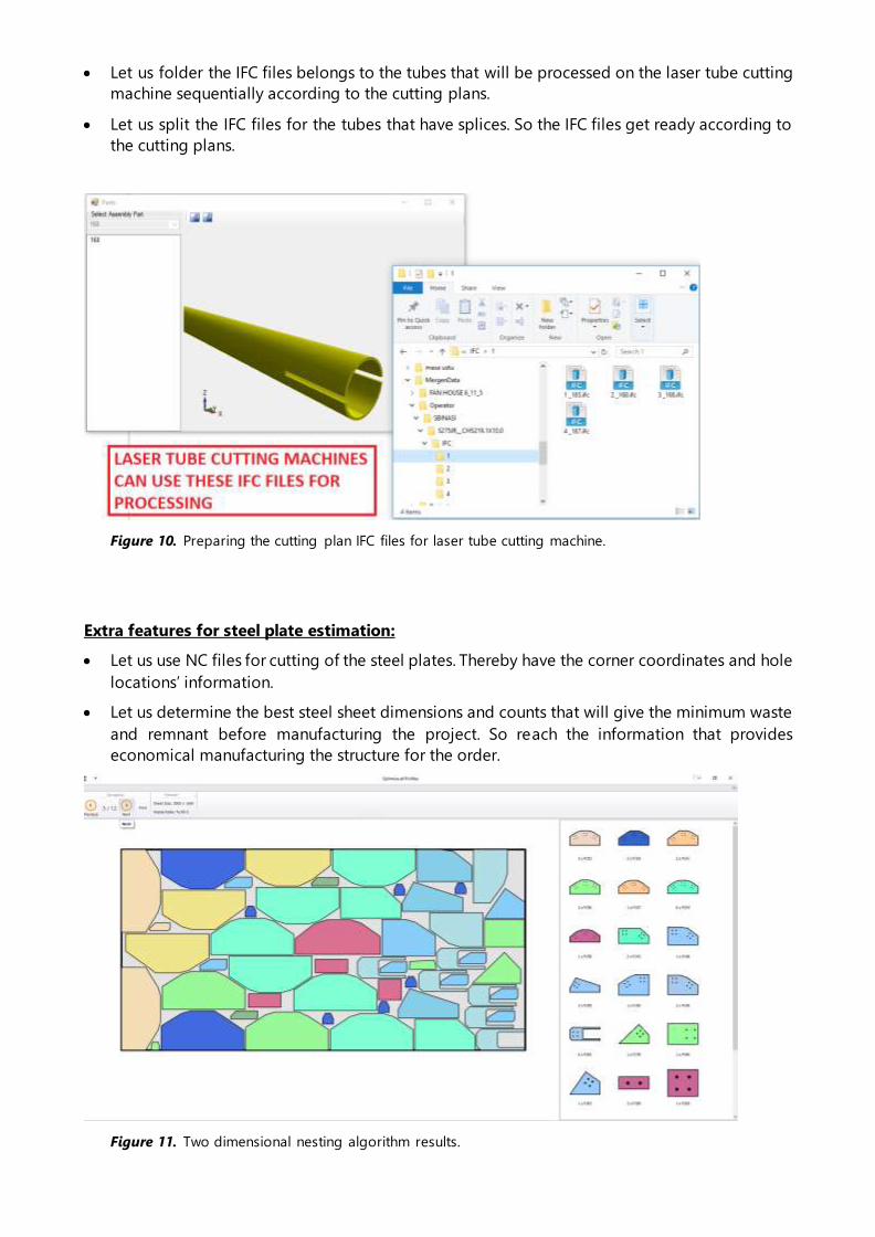
Let us folder the IFC files belongs to the tubes that will be processed on the laser tube cutting
machine sequentially according to the cutting plans.
Let us split the IFC files for the tubes that have splices. So the IFC files get ready according to
the cutting plans.
Figure 10. Preparing the cutting plan IFC files for laser tube cutting machine.
Extra features for steel plate estimation:
Let us use NC files for cutting of the steel plates. Thereby have the corner coordinates and hole
locations’ information.
Let us determine the best steel sheet dimensions and counts that will give the minimum waste
and remnant before manufacturing the project. So reach the information that provides
economical manufacturing the structure for the order.
Figure 11. Two dimensional nesting algorithm results.
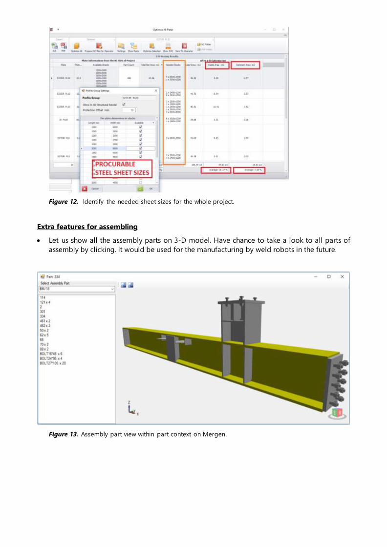
Figure 12. Identify the needed sheet sizes for the whole project.
Extra features for assembling
Let us show all the assembly parts on 3-D model. Have chance to take a look to all parts of
assembly by clicking. It would be used for the manufacturing by weld robots in the future.
Figure 13. Assembly part view within part context on Mergen.

D. CONCLUSION:
1. Via Mergen, cutting planning is done for the cutting of the structural members such as profiles,
plates and tubes by using the NC and IFC files. To folder the files (NC files for profiles, DXF files for
the tubes cut by oxy-plasma machines, IFC files for the tubes cut by laser tube cutting machines)
according to the cutting plans simplifies the operator’s job and minimizes the possibility of making
mistakes.
2. Via Mergen, waste and remnant parts amount can be decreased in serious ratio by our one
dimensional nesting algorithm that can make splices. Rework, which is arising from the clashes
between the splice point and bolt holes or welded members, is abolished.
3. Via Mergen, It is reached to the best economical structure by using the remnant parts from the
previous projects for steel profile groups and also ordering commensurately for the steel sheets,
finding best solution with the cutting after 2D optimization.
For competing in the market that has lots of competitors the economical solutions must be
served to the customers. One of the ways is decreasing the costs and the other way is
renouncing the earning in a certain extent. Being afloat and increasing in size are not
sustainable by renouncing the earning.
Mergen enables you to decrease your costs by less loss and less labor force requirement.
ANNEX:
Manisa Multi-Storey Car Park Project
Project information
Total area 12750 m2
Total part count 28830
NC file count 568
Total steel profile
weight
371 tones
Total steel plate
weight
115 tones
Total steel weight 486 tones
Annex
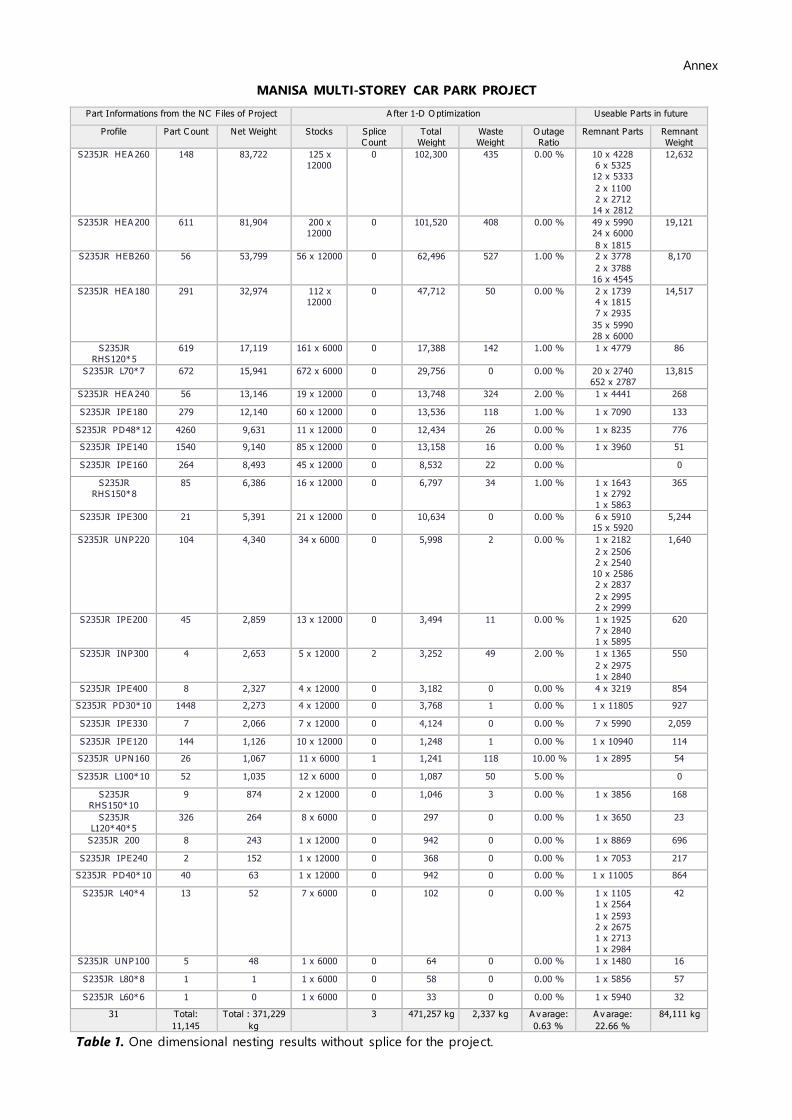
MANISA MULTI-STOREY CAR PARK PROJECT
Part Informations from the NC F iles of Project A fter 1-D O ptimization Useable Parts in future
Profile Part C ount Net Weight Stocks Splice
C ount
Total
Weight
Waste
Weight
O utage
Ratio
Remnant Parts Remnant
Weight
S235JR HEA 260 148 83,722 125 x
12000
0 102,300 435 0.00 % 10 x 4228
6 x 5325
12 x 5333
2 x 1100
2 x 2712
14 x 2812
12,632
S235JR HEA 200 611 81,904 200 x
12000
0 101,520 408 0.00 % 49 x 5990
24 x 6000
8 x 1815
19,121
S235JR HEB260 56 53,799 56 x 12000 0 62,496 527 1.00 % 2 x 3778
2 x 3788
16 x 4545
8,170
S235JR HEA 180 291 32,974 112 x
12000
0 47,712 50 0.00 % 2 x 1739
4 x 1815
7 x 2935
35 x 5990
28 x 6000
14,517
S235JR
RHS120*5
619 17,119 161 x 6000 0 17,388 142 1.00 % 1 x 4779 86
S235JR L70*7 672 15,941 672 x 6000 0 29,756 0 0.00 % 20 x 2740
652 x 2787
13,815
S235JR HEA 240 56 13,146 19 x 12000 0 13,748 324 2.00 % 1 x 4441 268
S235JR IPE180 279 12,140 60 x 12000 0 13,536 118 1.00 % 1 x 7090 133
S235JR PD48*12 4260 9,631 11 x 12000 0 12,434 26 0.00 % 1 x 8235 776
S235JR IPE140 1540 9,140 85 x 12000 0 13,158 16 0.00 % 1 x 3960 51
S235JR IPE160 264 8,493 45 x 12000 0 8,532 22 0.00 % 0
S235JR
RHS150*8
85 6,386 16 x 12000 0 6,797 34 1.00 % 1 x 1643
1 x 2792
1 x 5863
365
S235JR IPE300 21 5,391 21 x 12000 0 10,634 0 0.00 % 6 x 5910
15 x 5920
5,244
S235JR UNP220 104 4,340 34 x 6000 0 5,998 2 0.00 % 1 x 2182
2 x 2506
2 x 2540
10 x 2586
2 x 2837
2 x 2995
2 x 2999
1,640
S235JR IPE200 45 2,859 13 x 12000 0 3,494 11 0.00 % 1 x 1925
7 x 2840
1 x 5895
620
S235JR INP300 4 2,653 5 x 12000 2 3,252 49 2.00 % 1 x 1365
2 x 2975
1 x 2840
550
S235JR IPE400 8 2,327 4 x 12000 0 3,182 0 0.00 % 4 x 3219 854
S235JR PD30*10 1448 2,273 4 x 12000 0 3,768 1 0.00 % 1 x 11805 927
S235JR IPE330 7 2,066 7 x 12000 0 4,124 0 0.00 % 7 x 5990 2,059
S235JR IPE120 144 1,126 10 x 12000 0 1,248 1 0.00 % 1 x 10940 114
S235JR UPN160 26 1,067 11 x 6000 1 1,241 118 10.00 % 1 x 2895 54
S235JR L100*10 52 1,035 12 x 6000 0 1,087 50 5.00 % 0
S235JR
RHS150*10
9 874 2 x 12000 0 1,046 3 0.00 % 1 x 3856 168
S235JR
L120*40*5
326 264 8 x 6000 0 297 0 0.00 % 1 x 3650 23
S235JR 200 8 243 1 x 12000 0 942 0 0.00 % 1 x 8869 696
S235JR IPE240 2 152 1 x 12000 0 368 0 0.00 % 1 x 7053 217
S235JR PD40*10 40 63 1 x 12000 0 942 0 0.00 % 1 x 11005 864
S235JR L40*4 13 52 7 x 6000 0 102 0 0.00 % 1 x 1105
1 x 2564
1 x 2593
2 x 2675
1 x 2713
1 x 2984
42
S235JR UNP100 5 48 1 x 6000 0 64 0 0.00 % 1 x 1480 16
S235JR L80*8 1 1 1 x 6000 0 58 0 0.00 % 1 x 5856 57
S235JR L60*6 1 0 1 x 6000 0 33 0 0.00 % 1 x 5940 32
31 Total:
11,145
Total : 371,229
kg
3 471,257 kg 2,337 kg A v arage:
0.63 %
A v arage:
22.66 %
84,111 kg
Table 1. One dimensional nesting results without splice for the project.

Annex
MANISA MULTI-STOREY CAR PARK PROJECT
Part Informations from the NC F iles of Project A fter 1-D O ptimization Useable Parts in future
Profile Part C ount Net Weight Stocks Splice
C ount Total Weight
Waste
Weight
O utage
Ratio Remnant Parts
Remnant
Weight
S235JR HEA 260 148 83,722 109 x 12000 35 89,206 3,553 4.00 % 1 x 3246 221
S235JR HEA 200 611 81,904 163 x 12000 43 82,739 408 0.00 % 1 x 7630 323
S235JR HEB260 56 53,799 54 x 12000 2 60,264 547 1.00 % 14 x 4545 5,918
S235JR HEA 180 291 32,974 79 x 12000 40 33,654 181 1.00 % 1 x 9652 343
S235JR
RHS120*5
619 17,119 161 x 6000 0 17,388 142 1.00 % 1 x 4779 86
S235JR L70*7 672 15,941 182 x 12000 153 16,118 85 1.00 % 1 x 11142 82
S235JR HEA 240 56 13,146 19 x 12000 0 13,748 324 2.00 % 1 x 4441 268
S235JR IPE180 279 12,140 60 x 12000 0 13,536 118 1.00 % 1 x 7090 133
S235JR IPE140 1540 9,140 85 x 12000 0 13,158 16 0.00 % 1 x 3960 51
S235JR PD48*12 4260 9,631 11 x 12000 0 12,434 26 0.00 % 1 x 8235 776
S235JR IPE160 264 8,493 45 x 12000 0 8,532 22 0.00 % 0
S235JR
RHS150*8
85 6,386 16 x 12000 0 6,797 34 1.00 % 1 x 1643
1 x 2792
1 x 5863
365
S235JR IPE300 21 5,391 11 x 12000 10 5,570 56 1.00 % 1 x 2844 120
S235JR UNP220 104 4,340 25 x 6000 14 4,410 21 0.00 % 1 x 1306 38
S235JR INP300 4 2,653 5 x 12000 2 3,252 49 2.00 % 1 x 1365
2 x 2975
1 x 2840
550
S235JR IPE200 45 2,859 11 x 12000 5 2,957 32 1.00 % 1 x 2846 64
S235JR PD30*10 1448 2,273 3 x 12000 0 2,826 2 0.00 % 1 x 4126 324
S235JR IPE400 8 2,327 3 x 12000 2 2,387 57 2.00 % 0
S235JR IPE330 7 2,066 4 x 12000 3 2,357 48 2.00 % 1 x 4914 241
S235JR IPE120 144 1,126 10 x 12000 0 1,248 1 0.00 % 1 x 10940 114
S235JR UPN160 26 1,067 11 x 6000 1 1,241 118 10.00 % 1 x 2895 54
S235JR L100*10 52 1,035 12 x 6000 0 1,087 50 5.00 % 0
S235JR
RHS150*10
9 874 2 x 12000 0 1,046 3 0.00 % 1 x 3856 168
S235JR PD40*10 40 63 1 x 12000 0 942 0 0.00 % 1 x 11122 873
S235JR 200 8 243 1 x 12000 0 942 0 0.00 % 1 x 8869 696
S235JR IPE240 2 152 1 x 12000 0 368 0 0.00 % 1 x 7053 217
S235JR
L120*40*5
326 264 8 x 6000 0 297 0 0.00 % 1 x 3650 23
S235JR L40*4 13 52 6 x 6000 1 87 2 3.00 % 1 x 2593
2 x 2675
1 x 2713
26
S235JR UNP100 5 48 1 x 6000 0 64 0 0.00 % 1 x 1480 16
S235JR L80*8 1 1 1 x 6000 0 58 0 0.00 % 1 x 5856 57
S235JR L60*6 1 0 1 x 6000 0 33 0 0.00 % 1 x 5940 32
31 Total:
11,145
Total :
371,229 kg
311 398,746 kg 5,895 kg A v arage:
1.59 %
A v arage:
3.28 %
12,179 kg
Table 2. One dimensional nesting results with splice option for the project.
Outage
ratio (%)
Outage
weight (kg)
Remnant
ratio (%)
Remnant
weight (kg)
Needed
weight (kg)
Without Splice 0,63 2337 22,66 84111 471257
With Splice 1,59 5895 3,28 12179 398746
Difference -0,96 -3558 19,38 71932 72511
Table 3. Comparing tables between with or without making splice option.
Annex
MANISA MULTI-STOREY CAR PARK PROJECT
Plate Informations from the NC F iles of Project A fter 2-D O ptimization
P late Thickness
mm Part C ount
Total Net A rea
m2 Needed Stocks
Used A rea
m2
Waste A rea
m2
Remnant A rea
m2
S235JR
PLT12 12.0 2293 255.55 24 x 6000x2000 288.00 47.84 0.00
S235JR
PLT10 10.0 6959 225.69
1 x 6000x2000
13 x 10000x2000 272.00 43.82 2.49
S235JR
PLT15 15.0 2821 153.49
2 x 6000x2000
8 x 10000x2000 184.00 28.44 2.07
S235JR
PLT20 20.0 1304 123.59
6 x 10000x2000
1 x 8000x2000 136.00 12.41 0.00
S235JR
PLT8 8.0 3322 88.50
6 x 2400x1200
1 x 6000x1500
4 x 10000x2000
106.28 17.78 0.00
S235JR
PL900 3.0 206 67.35
1 x 4000x1500
3 x 10000x2000
1 x 4000x2000
74.00 6.65 0.00
S235JR
PLT6 6.0 2105 62.64
1 x 8000x2000
4 x 10000x2000
1 x 4000x2000
104.00 36.92 4.45
S235JR
PLT5 5.0 2912 43.87
2 x 10000x2000
1 x 6000x2000 52.00 8.13 0.00
S235JR
PLT40 40.0 524 28.47
1 x 10000x2000
1 x 6000x2000 32.00 3.53 0.00
S235JR
PL150 20.0 852 12.78 1 x 8000x2000 16.00 3.22 0.00
S235JR
F LT50 5.0 308 10.68 1 x 8000x2000 16.00 2.67 2.65
S235JR
PLT3 3.0 26 8.04 1 x 6000x2000 12.00 0.64 3.32
S235JR
PLT30 30.0 8 2.40 1 x 2500x1250 3.13 0.73 0.00
S235JR
PL10 10.0 39 1.09 1 x 4000x1500 6.00 3.57 1.34
S235JR
PLT25 25.0 2 0.51 1 x 2000x1000 2.00 0.03 1.46
S235JR
PL54 3.0 6 0.18 1 x 2000x1000 2.00 0.69 1.14
Total: 23,843
Total : 1482.82 m2
Total : 115,889.24 kg
1305.41
m2
217.06 m2
A v arage: 16.21 %
18.91 m2
A v arage: 1.08 %
Table 4. Two dimensional nesting results.
From BIM
Software
Mergen nesting with no
splice option
Mergen nesting with splice
option
Needed Plate (kg) 115889 135926 135926
Needed Profile (kg) 371229 471257 398746
Total (kg) 487118 607183 534672
Success ratio (%) 100.00 78.84 91.10
Table 5. Assessment of the project